assembly and parts list manual - e. bourassa · assembly and parts list manual ... b16 steering...
TRANSCRIPT

www.meridianmfg.com
ASSEMBLY AND
PARTS LIST MANUAL
FRAME MOUNT
AUGER MOVER
®

GENERAL
A1
DECLARATION OF CONFORMITY
We the Manufacturer:
Meridian Manufacturing Inc.PO Box 1996 2800 Pasqua Street North
Regina, Sk,CanadaS4P 3E1
Declare the Movers listed below conform to the 2006/42/EC MachineryDirective
Frame Mount Mover Series
WFN 992-997
The Meridian Mover Frame Mount
is designed for the movement of Grain and Cereal Augers.
13000043247-00-02
GENERAL
A2
TABLE OF CONTENTSGENERAL
A1 Declaration of ConformityA2 Table of ContentsA3 Sign Off Sheet ASSEMBLY
B1 Wheel Drive AssemblyB3 Wheel & Yoke AssemblyB5 Walking Beam AssemblyB8 Lift AssemblyB14 Lift & Walking Beam AssemblyB16 Steering Column AssemblyB17 Transport Chain AssemblyB18 Hydraulic Pump AssemblyB20 Hydraulic Winch AssemblyB23 Hydraulics AssemblyB32 Frame Belt Idler AssemblyB34 Decal Assembly PARTS
C1 Walking BeamC3 Lift AssemblyC5 Steering Column c/w HydraulicsC6 Drive Motor - LHC7 Drive Motor - RHC8 Hydraulic WinchC9 Pump Tank and FilterC11 Pump - Big BlockC12 Pump - Small BlockC13 Belt IdlerC14 Belt TensionerC15 Hose Kit - 33' & 39'C16 Hose Kit - 46'C17 Hose Kit - 53' & 59' INDEX
D1 Parts Index WARRANTY
E1 Limited Warranty Statement
13000043247-01-00
GENERAL
A3
MERIDIAN GRAIN EQUIPMENT SIGNOFF SHEET
As a requirement of OSHA, it is necessary for the employer to train the employee in the safe operation and safety procedures with this equipment. We include this sign-off sheet for your convenience and personal record keeping.
13000004273-10-00
ASSEMBLY
B1
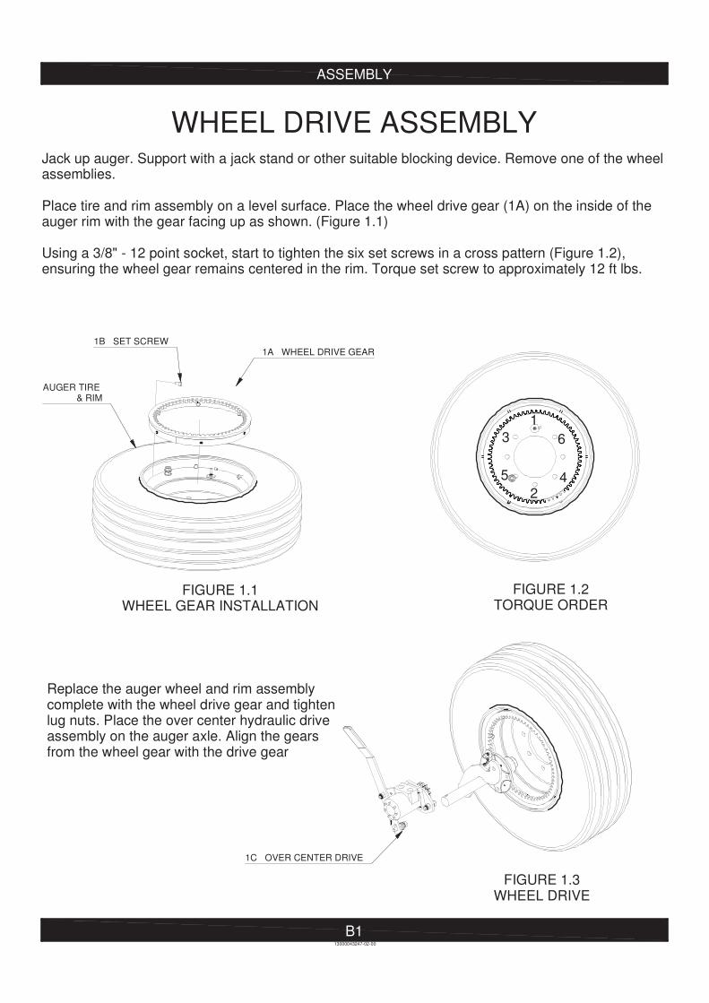
WHEEL DRIVE ASSEMBLYJack up auger. Support with a jack stand or other suitable blocking device. Remove one of the wheel assemblies. Place tire and rim assembly on a level surface. Place the wheel drive gear (1A) on the inside of the auger rim with the gear facing up as shown. (Figure 1.1) Using a 3/8" - 12 point socket, start to tighten the six set screws in a cross pattern (Figure 1.2), ensuring the wheel gear remains centered in the rim. Torque set screw to approximately 12 ft lbs.
Replace the auger wheel and rim assembly complete with the wheel drive gear and tightenlug nuts. Place the over center hydraulic drive assembly on the auger axle. Align the gears from the wheel gear with the drive gear
FIGURE 1.1WHEEL GEAR INSTALLATION
FIGURE 1.2TORQUE ORDER
FIGURE 1.3WHEEL DRIVE
1
2
3
45
6
13000043247-02-00
1A WHEEL DRIVE GEAR
AUGER TIRE & RIM
1C OVER CENTER DRIVE
1B SET SCREW
J
J
N
ASSEMBLY
B2
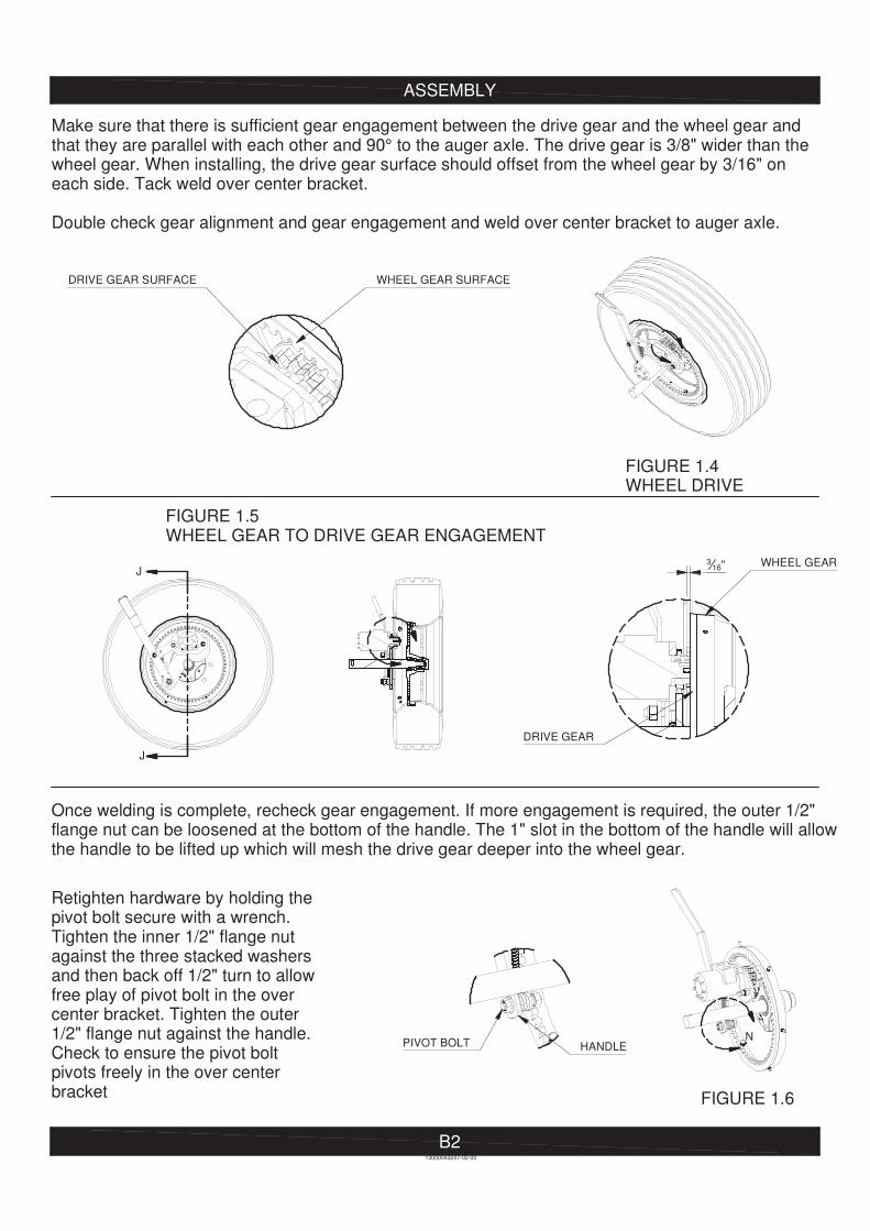
Make sure that there is sufficient gear engagement between the drive gear and the wheel gear and that they are parallel with each other and 90° to the auger axle. The drive gear is 3/8" wider than the wheel gear. When installing, the drive gear surface should offset from the wheel gear by 3/16" on each side. Tack weld over center bracket. Double check gear alignment and gear engagement and weld over center bracket to auger axle.
Once welding is complete, recheck gear engagement. If more engagement is required, the outer 1/2" flange nut can be loosened at the bottom of the handle. The 1" slot in the bottom of the handle will allowthe handle to be lifted up which will mesh the drive gear deeper into the wheel gear. Retighten hardware by holding thepivot bolt secure with a wrench. Tighten the inner 1/2" flange nut against the three stacked washersand then back off 1/2" turn to allowfree play of pivot bolt in the over center bracket. Tighten the outer 1/2" flange nut against the handle.Check to ensure the pivot bolt pivots freely in the over center bracket
FIGURE 1.4WHEEL DRIVE
FIGURE 1.5WHEEL GEAR TO DRIVE GEAR ENGAGEMENT
FIGURE 1.6
DRIVE GEAR SURFACE WHEEL GEAR SURFACE
DRIVE GEAR
13000043247-02-00
316" WHEEL GEAR
PIVOT BOLT HANDLE
ASSEMBLY
B3
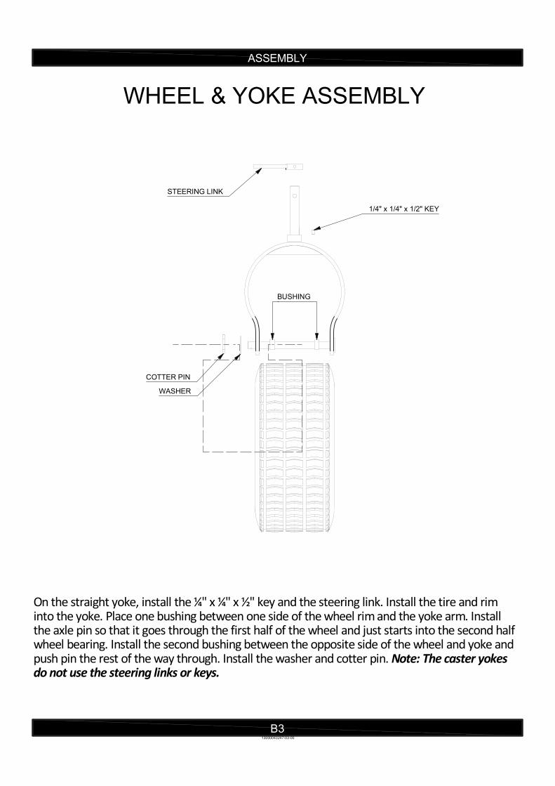
WHEEL & YOKE ASSEMBLY
On the straight yoke, install the ¼" x ¼" x ½" key and the steering link. Install the tire and rim into the yoke. Place one bushing between one side of the wheel rim and the yoke arm. Install the axle pin so that it goes through the first half of the wheel and just starts into the second half wheel bearing. Install the second bushing between the opposite side of the wheel and yoke and push pin the rest of the way through. Install the washer and cotter pin. Note: The caster yokes do not use the steering links or keys.
13000043247-03-00
1/4" x 1/4" x 1/2" KEY
STEERING LINK
COTTER PIN
WASHER
BUSHING

ASSEMBLY
B4
When complete, you will have two straight yoke/wheel assemblies with steering links and two caster yoke/wheel assemblies without steering links.
13000043247-03-00
STRAIGHT YOKE WITH STEERING LINK CASTER YOKE

ASSEMBLY
B5
WALKING BEAM ASSEMBLY
Walking Beam Assembly (Left Hand)
13000043247-04-00
WALKING BEAM
STEERING ROD
3/8"x1-1/2" CAP SCREWWASHER
LOCK NUT
TIE ROD END
INSTALL WASHER BETWEENSTEERING ROD & LINK
STEERING LINK
STRAIGHT EDGE
CHAIN HOOK
13000043247-04-00
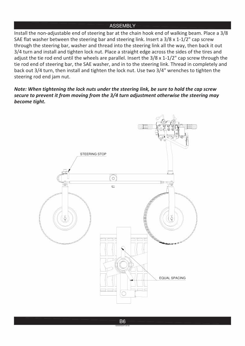
B6
ASSEMBLY
EQUAL SPACING
STEERING STOP

ASSEMBLY
B713000043247-04-00
NUT AND BOLT
WASHER
ASSEMBLY
B8
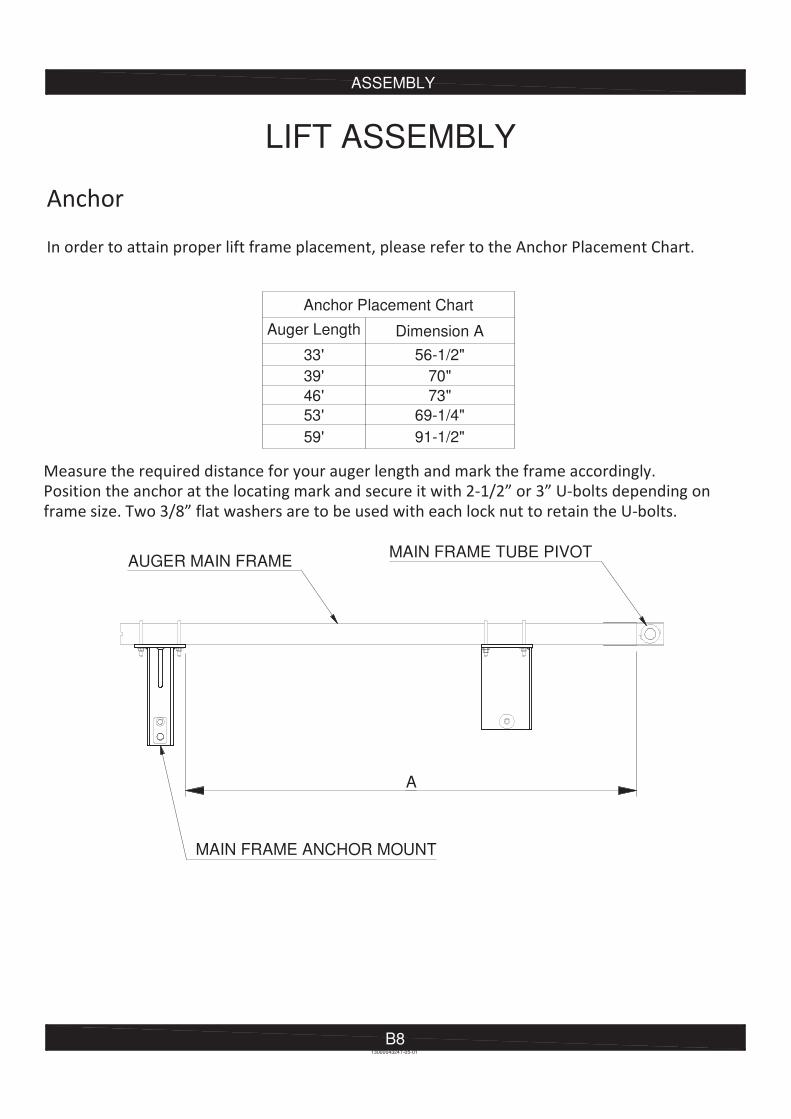
LIFT ASSEMBLY
Anchor Placement Chart
Auger Length Dimension A
33' 56-1/2"
39' 70"
46' 73"
53' 69-1/4"
59' 91-1/2"
13000043247-05-01
A
AUGER MAIN FRAMEMAIN FRAME TUBE PIVOT
MAIN FRAME ANCHOR MOUNT
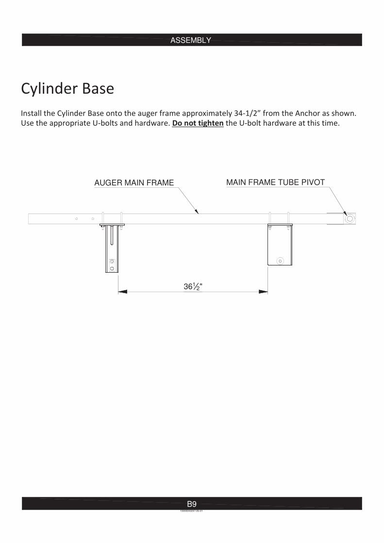
ASSEMBLY
B913000043247-05-01
AUGER MAIN FRAME MAIN FRAME TUBE PIVOT
3612"
ASSEMBLY
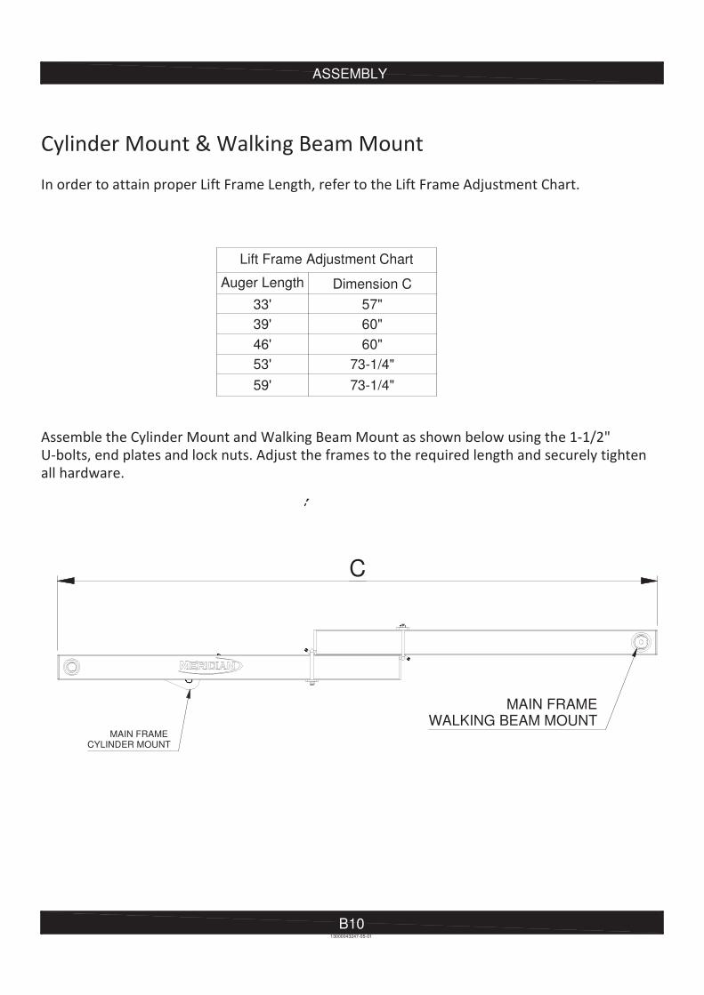
B10
Lift Frame Adjustment Chart
Auger Length Dimension C
33' 57"
39' 60"
46' 60"
53' 73-1/4"
59' 73-1/4"
13000043247-05-01
C
MAIN FRAME CYLINDER MOUNT
MAIN FRAMEWALKING BEAM MOUNT
ASSEMBLY
B1113000043247-05-01
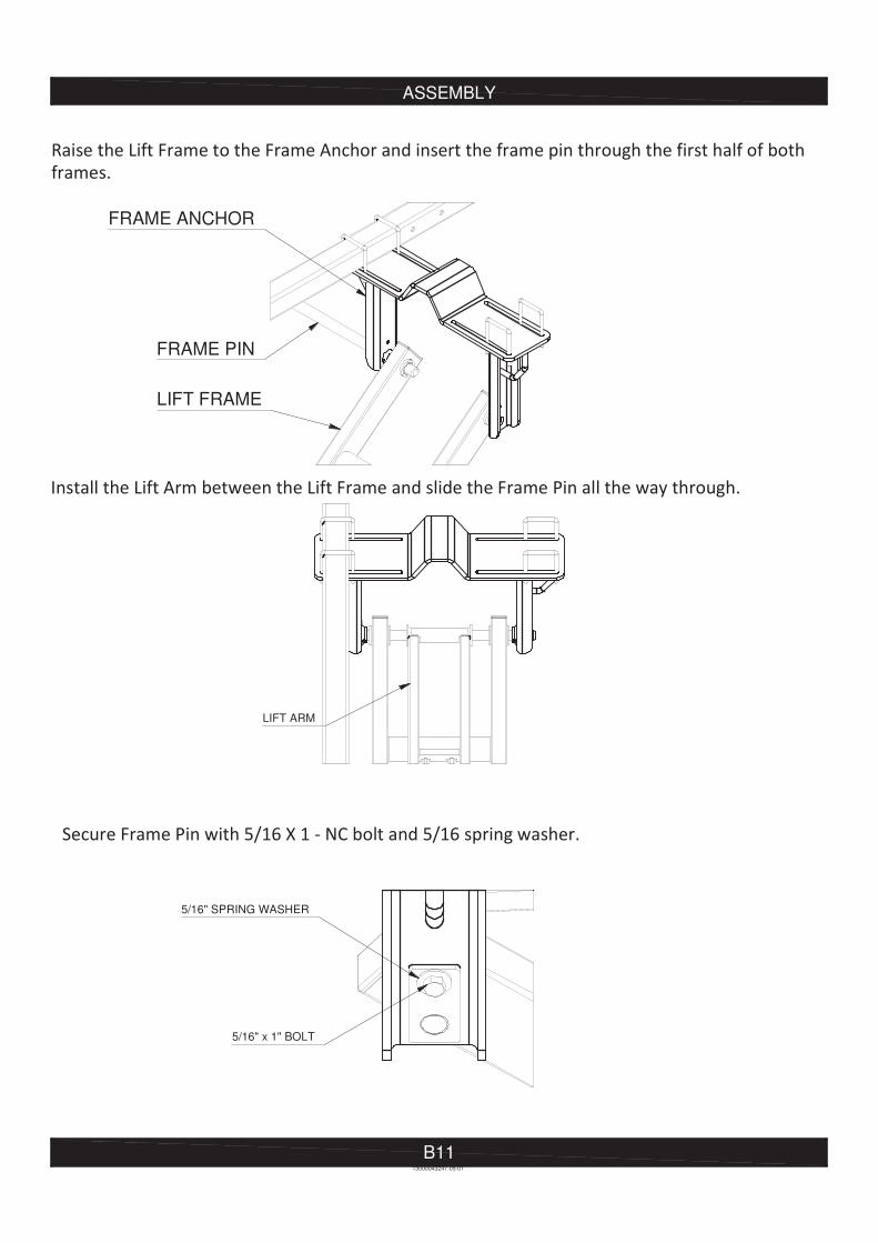
5/16" SPRING WASHER
5/16" x 1" BOLT
LIFT ARM
FRAME PIN
FRAME ANCHOR
LIFT FRAME
ASSEMBLY
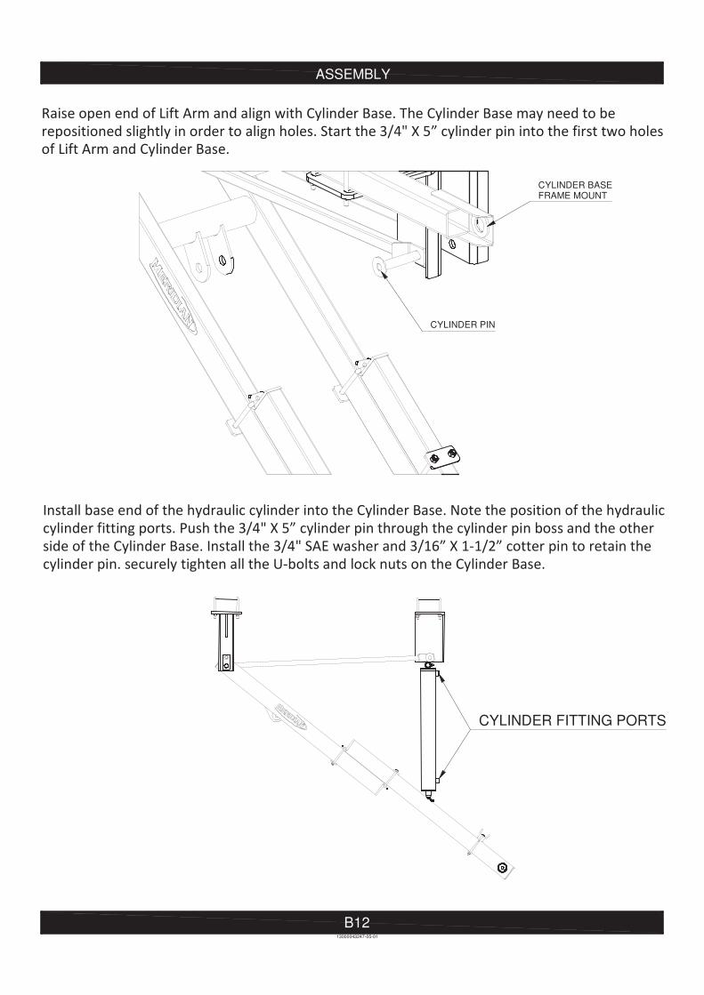
B1213000043247-05-01
CYLINDER PIN
CYLINDER FITTING PORTS
CYLINDER BASEFRAME MOUNT
ASSEMBLY
B1313000043247-05-01
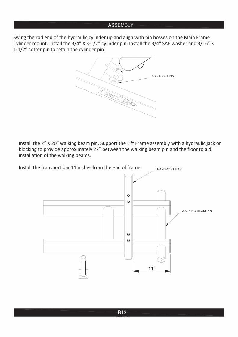
CYLINDER PIN
11"
TRANSPORT BAR
WALKING BEAM PIN
ASSEMBLY
B1413000043247-06-00
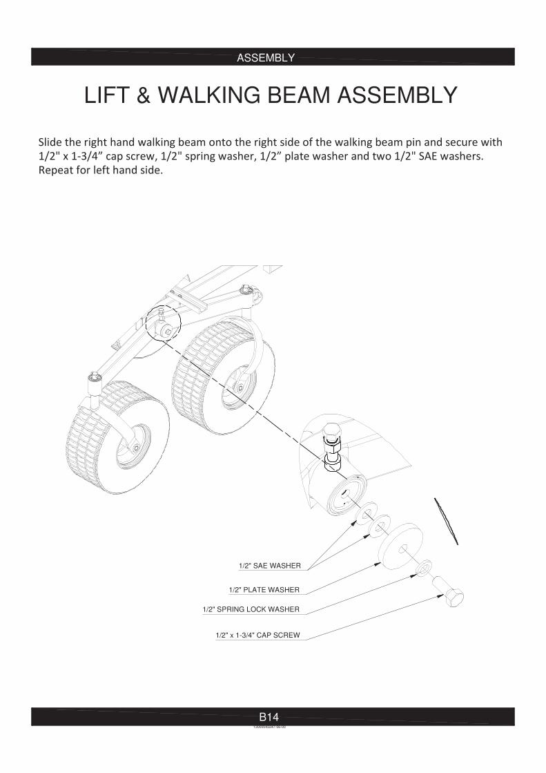
LIFT & WALKING BEAM ASSEMBLY
1/2" SAE WASHER
1/2" PLATE WASHER
1/2" SPRING LOCK WASHER
1/2" x 1-3/4" CAP SCREW
ASSEMBLY
B1513000043247-06-00
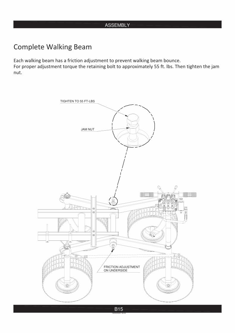
FRICTION ADJUSTMENTON UNDERSIDE
TIGHTEN TO 55 FT-LBS
JAM NUT
ASSEMBLY
B16
STEERING COLUMN ASSEMBLY
13000043247-07-00
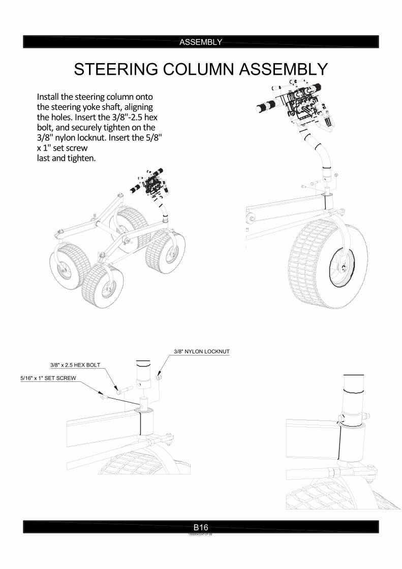
Install the steering column onto the steering yoke shaft, aligning the holes. Insert the 3/8"-2.5 hex bolt, and securely tighten on the 3/8" nylon locknut. Insert the 5/8"x 1" set screwlast and tighten.
3/8" x 2.5 HEX BOLT
3/8" NYLON LOCKNUT
5/16" x 1" SET SCREW

ASSEMBLY
B17
TRANSPORT CHAIN ASSEMBLY
Transport Chain for 33, 39 and 46 Foot Augers Secure the two transport chains on each side of the Cylinder Base with a 3/8 x 1-1/4" cap screw, two 3/8" flat washers and 3/8" nylon lock nut. Fasten Quick Link onto the other end of the chain.
Transport Chain for 53 and 59 Foot Augers Secure each transport chain with the cable roller bracket retaining pins.
13000043247-08-00
CAP SCREW WITH TWO WASHERS ON THE TOP OF THE CHAIN AND NYLONLOCK NUT UNDER THE FRAME MOUNT
LOOP CHAIN AND CONNECTWALKING BEAM AND BACK TO CHAIN WITH QUICK CONNECT
CABLE ROLLER BRACKET
ATTACH ENDS TO WALKING BEAM
AT CHAIN ATTACHMENT

ASSEMBLY
B18
HYDRAULIC PUMP ASSEMBLY
13000043247-09-00
MUST HAVE 3/8" FLAT WASHERS TO PREVENT SLOTTED BRACKETFROM TIPPING
MOUNTING BOLTS
ASSEMBLY
B1913000043247-09-00
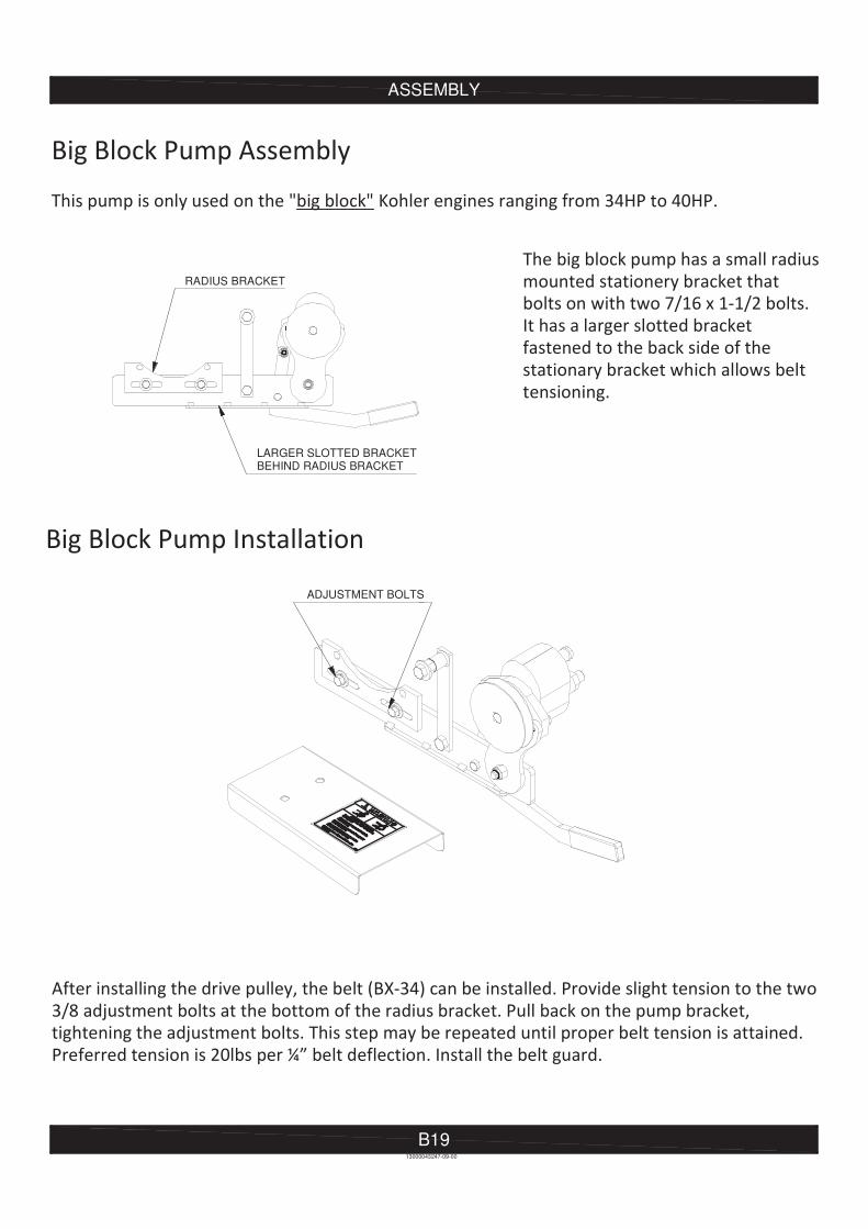
RADIUS BRACKET
LARGER SLOTTED BRACKETBEHIND RADIUS BRACKET
ADJUSTMENT BOLTS
ASSEMBLY
B20
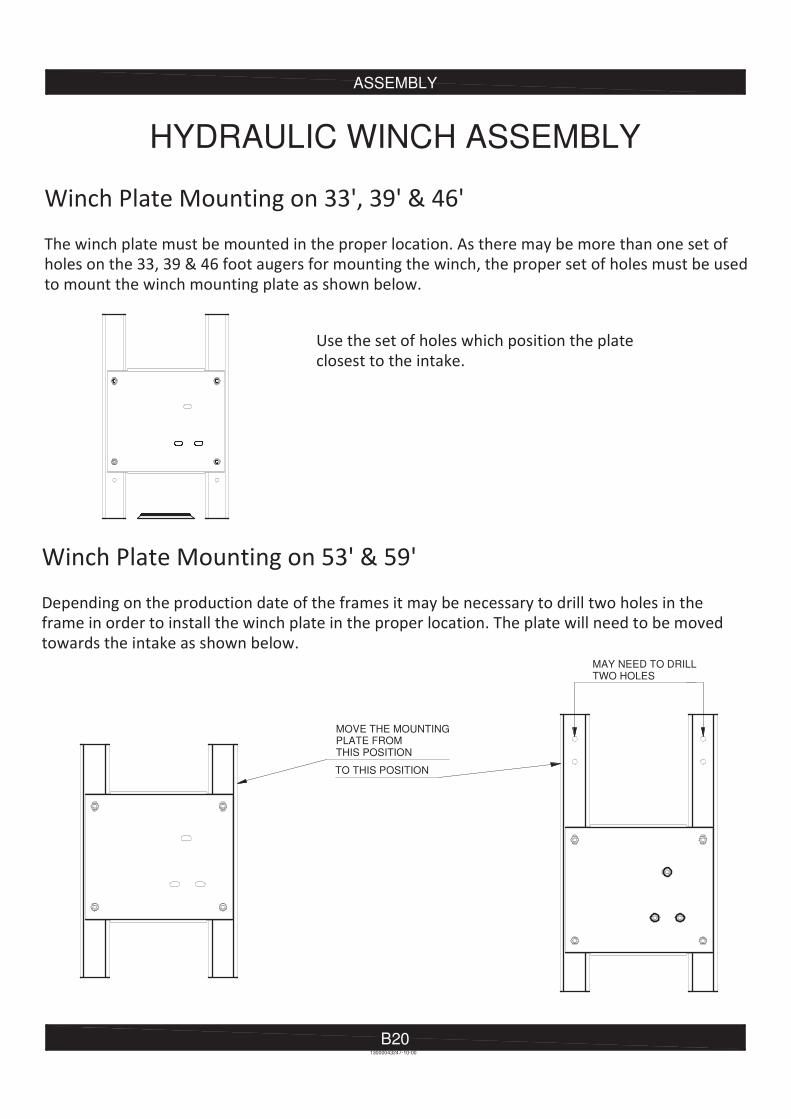
HYDRAULIC WINCH ASSEMBLY
13000043247-10-00
MOVE THE MOUNTINGPLATE FROMTHIS POSITION
TO THIS POSITION
MAY NEED TO DRILLTWO HOLES
ASSEMBLY
B2113000043247-10-00
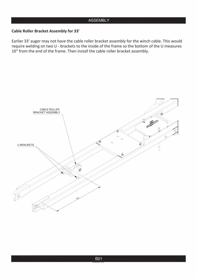
CABLE ROLLER BRACKET ASSEMBLY
U BRACKETS
ASSEMBLY
B22
13000043247-10-00
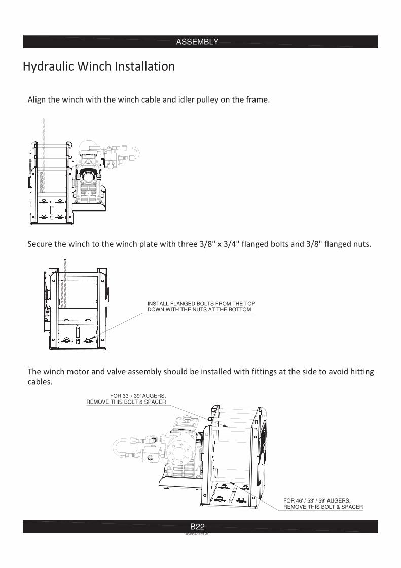
FOR 33' / 39' AUGERS,REMOVE THIS BOLT & SPACER
FOR 46' / 53' / 59' AUGERS,REMOVE THIS BOLT & SPACER
INSTALL FLANGED BOLTS FROM THE TOPDOWN WITH THE NUTS AT THE BOTTOM
ASSEMBLY
B23
HYDRAULICS ASSEMBLY
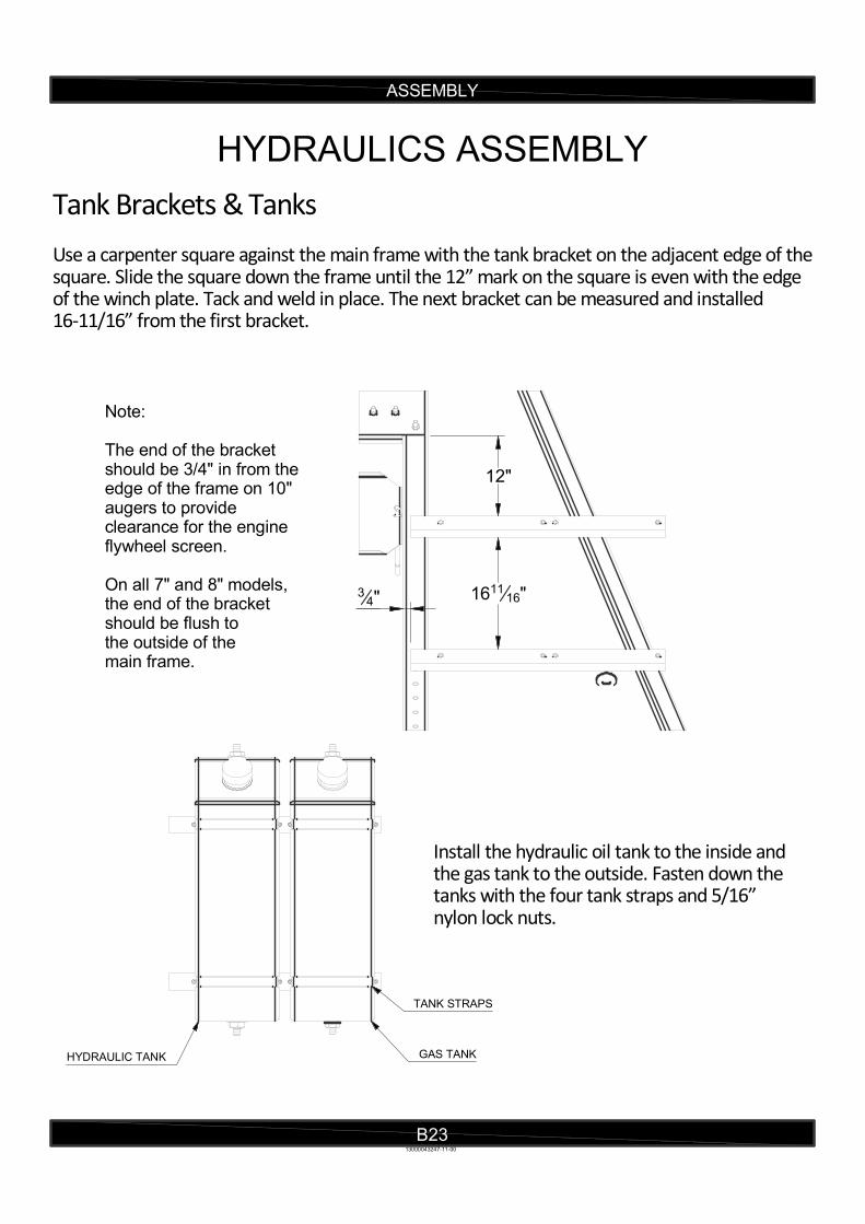
Tank Brackets & Tanks Use a carpenter square against the main frame with the tank bracket on the adjacent edge of the square. Slide the square down the frame until the 12” mark on the square is even with the edge of the winch plate. Tack and weld in place. The next bracket can be measured and installed 16-11/16” from the first bracket.
Install the hydraulic oil tank to the inside and the gas tank to the outside. Fasten down the tanks with the four tank straps and 5/16” nylon lock nuts.
13000043247-11-00
GAS TANKHYDRAULIC TANK
TANK STRAPS
12"
161116"3
4"
Note: The end of the bracket should be 3/4" in from the edge of the frame on 10" augers to provide clearance for the engine flywheel screen. On all 7" and 8" models,the end of the bracketshould be flush to the outside of the main frame.

ASSEMBLY
B24
Hydraulic Filter Head Mounting Bracket The hydraulic filter mounting bracket is mounted in different locations on different model augers as follows:
Secure filter mounting bracket with 2-1/2” or 3” U-bolt, depending on frame size, 1” ahead of the winch mounting plate.
Secure filter mounting bracket to bottom of Anchor using the 3/8" Stover lock nuts.
Secure filter mounting bracket with 2-1/2" or3" U-bolt, depending on frame size, 12-1/2" from end of brace.
13000043247-11-00
33 & 39 Foot
1"
121 2"
53 & 59 Foot
46 Foot
B
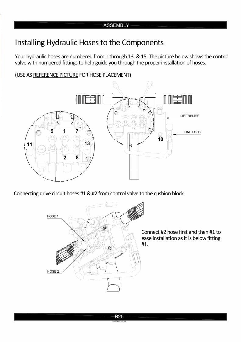
Installing Hydraulic Hoses to the Components Your hydraulic hoses are numbered from 1 through 13, & 15. The picture below shows the controlvalve with numbered fittings to help guide you through the proper installation of hoses. (USE AS REFERENCE PICTURE FOR HOSE PLACEMENT)
Connecting drive circuit hoses #1 & #2 from control valve to the cushion block
Connect #2 hose first and then #1 to ease installation as it is below fitting #1.
ASSEMBLY
B2513000043247-11-00
LIFT RELIEF
LINE LOCK9 1
7
2 8
1311
10
HOSE 1
HOSE 2
D
ASSEMBLY
B26
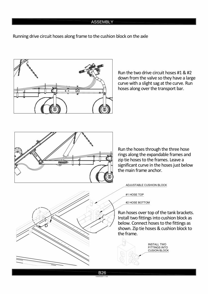
Running drive circuit hoses along frame to the cushion block on the axle
Run the two drive circuit hoses #1 & #2 down from the valve so they have a largecurve with a slight sag at the curve. Run hoses along over the transport bar.
Run the hoses through the three hose rings along the expandable frames andzip tie hoses to the frames. Leave a significant curve in the hoses just below the main frame anchor.
Run hoses over top of the tank brackets.Install two fittings into cushion block as below. Connect hoses to the fittings as shown. Zip tie hoses & cushion block to the frame.
13000043247-11-00
INSTALL TWO FITTINGS INTO CUSION BLOCK
ADJUSTABLE CUSHION BLOCK
#1 HOSE TOP
#2 HOSE BOTTOM
ASSEMBLY
B27
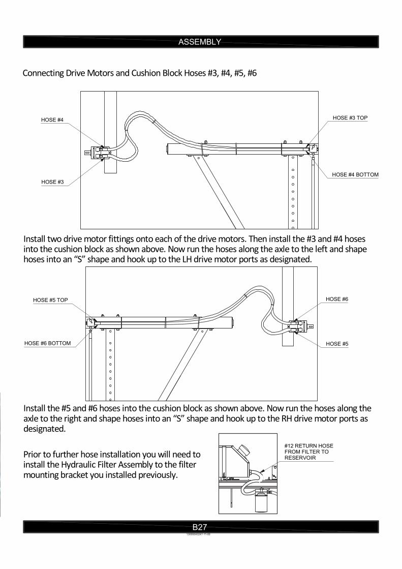
Connecting Drive Motors and Cushion Block Hoses #3, #4, #5, #6
Install two drive motor fittings onto each of the drive motors. Then install the #3 and #4 hoses into the cushion block as shown above. Now run the hoses along the axle to the left and shape hoses into an “S” shape and hook up to the LH drive motor ports as designated.
Install the #5 and #6 hoses into the cushion block as shown above. Now run the hoses along the axle to the right and shape hoses into an “S” shape and hook up to the RH drive motor ports as designated.
Prior to further hose installation you will need to install the Hydraulic Filter Assembly to the filter mounting bracket you installed previously.
13000043247-11-00
HOSE #4
HOSE #3
HOSE #3 TOP
HOSE #4 BOTTOM
HOSE #5 TOP
HOSE #6 BOTTOM
HOSE #6
HOSE #5
#12 RETURN HOSEFROM FILTER TORESERVOIR
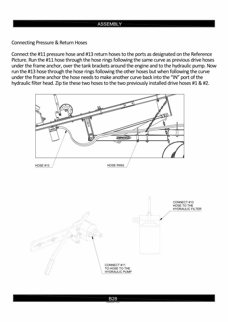
Connecting Pressure & Return Hoses
Connect the #11 pressure hose and #13 return hoses to the ports as designated on the Reference Picture. Run the #11 hose through the hose rings following the same curve as previous drive hoses under the frame anchor, over the tank brackets around the engine and to the hydraulic pump. Now run the #13 hose through the hose rings following the other hoses but when following the curve under the frame anchor the hose needs to make another curve back into the “IN” port of the hydraulic filter head. Zip tie these two hoses to the two previously installed drive hoses #1 & #2.
ASSEMBLY
B2813000043247-11-00
HOSE #13 HOSE RING
CONNECT #13HOSE TO THE HYDRAULIC FILTER
CONNECT #11 TO HOSE TO THEHYDRAULIC PUMP
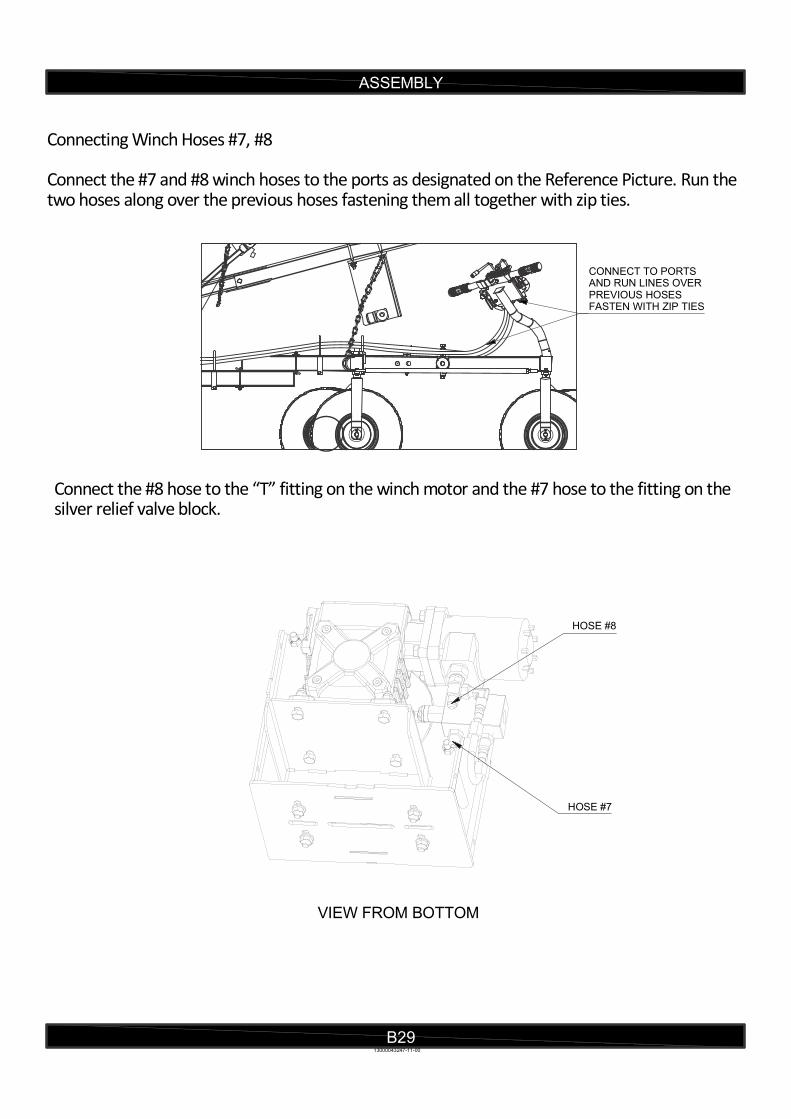
Connecting Winch Hoses #7, #8
Connect the #7 and #8 winch hoses to the ports as designated on the Reference Picture. Run the two hoses along over the previous hoses fastening them all together with zip ties.
Connect the #8 hose to the “T” fitting on the winch motor and the #7 hose to the fitting on the silver relief valve block.
ASSEMBLY
B2913000043247-11-00
CONNECT TO PORTSAND RUN LINES OVER PREVIOUS HOSESFASTEN WITH ZIP TIES
HOSE #8
HOSE #7
VIEW FROM BOTTOM
ASSEMBLY
B30
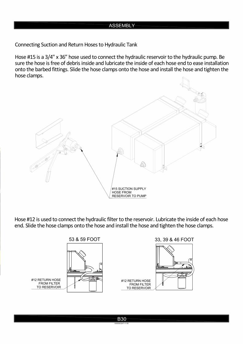
Connecting Suction and Return Hoses to Hydraulic Tank Hose #15 is a 3/4" x 36” hose used to connect the hydraulic reservoir to the hydraulic pump. Be sure the hose is free of debris inside and lubricate the inside of each hose end to ease installation onto the barbed fittings. Slide the hose clamps onto the hose and install the hose and tighten the hose clamps.
Hose #12 is used to connect the hydraulic filter to the reservoir. Lubricate the inside of each hose end. Slide the hose clamps onto the hose and install the hose and tighten the hose clamps.
13000043247-11-00
#12 RETURN HOSEFROM FILTER
TO RESERVOIR
#15 SUCTION SUPPLYHOSE FROMRESERVOIR TO PUMP
53 & 59 FOOT 33, 39 & 46 FOOT
#12 RETURN HOSEFROM FILTER
TO RESERVOIR
ASSEMBLY
B31
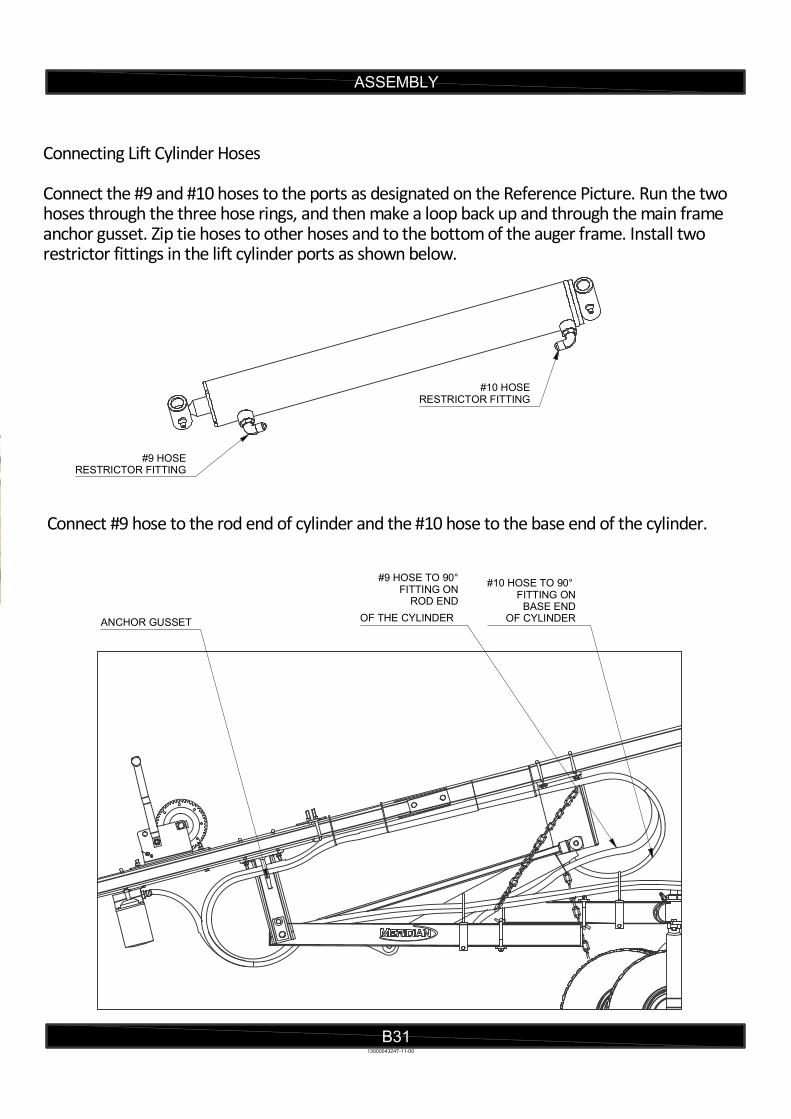
Connecting Lift Cylinder Hoses
Connect the #9 and #10 hoses to the ports as designated on the Reference Picture. Run the two hoses through the three hose rings, and then make a loop back up and through the main frame anchor gusset. Zip tie hoses to other hoses and to the bottom of the auger frame. Install two restrictor fittings in the lift cylinder ports as shown below.
Connect #9 hose to the rod end of cylinder and the #10 hose to the base end of the cylinder.
13000043247-11-00
#10 HOSE TO 90° FITTING ON
BASE ENDOF CYLINDER
#9 HOSE TO 90°FITTING ON
ROD END
OF THE CYLINDER
#9 HOSERESTRICTOR FITTING
#10 HOSERESTRICTOR FITTING
ANCHOR GUSSET
ASSEMBLY
B32
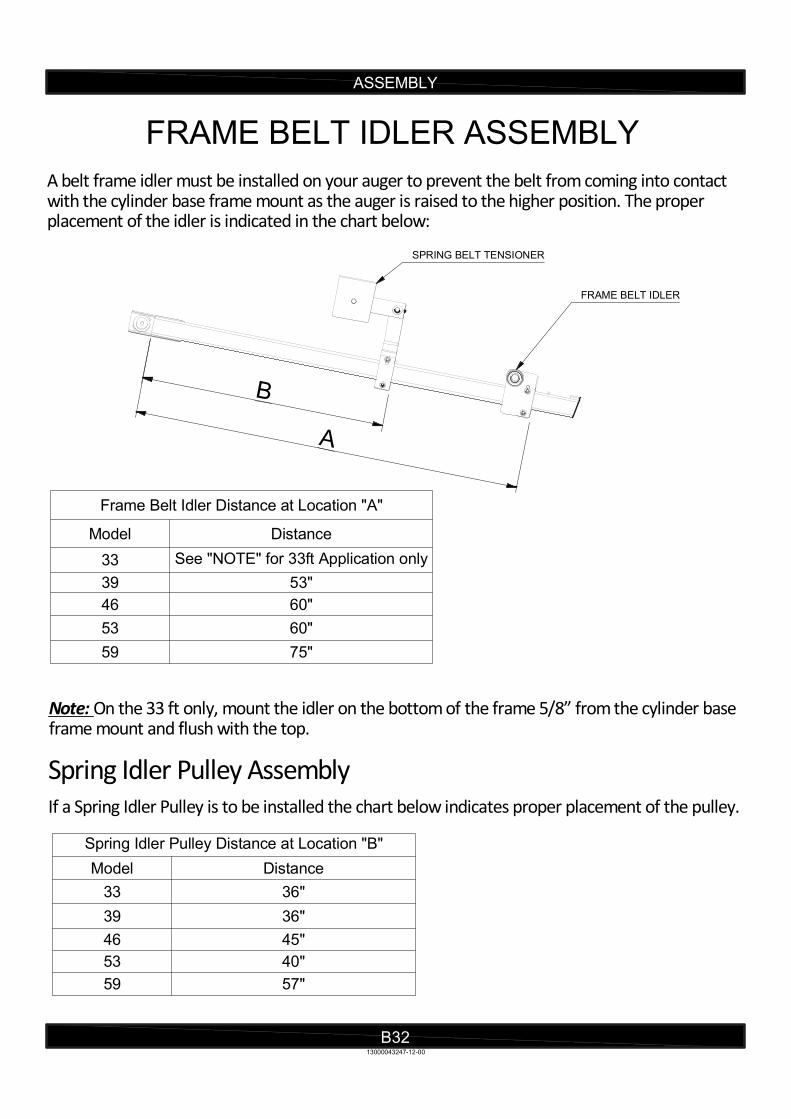
FRAME BELT IDLER ASSEMBLY
A belt frame idler must be installed on your auger to prevent the belt from coming into contact with the cylinder base frame mount as the auger is raised to the higher position. The proper placement of the idler is indicated in the chart below:
Frame Belt Idler Distance at Location "A"
Model Distance
33 See "NOTE" for 33ft Application only
39 53"
46 60"
53 60"
59 75"
Spring Idler Pulley Assembly
If a Spring Idler Pulley is to be installed the chart below indicates proper placement of the pulley.
Spring Idler Pulley Distance at Location "B"
Model Distance
33 36"
39 36"
46 45"
53 40"
59 57"
13000043247-12-00
Note: On the 33 ft only, mount the idler on the bottom of the frame 5/8” from the cylinder base frame mount and flush with the top.
FRAME BELT IDLER
SPRING BELT TENSIONER
A
B
B33
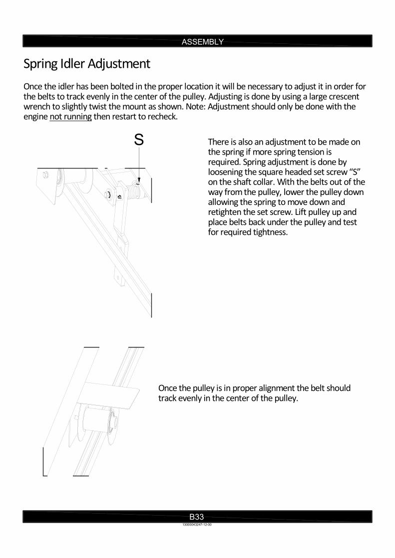
Spring Idler Adjustment Once the idler has been bolted in the proper location it will be necessary to adjust it in order for the belts to track evenly in the center of the pulley. Adjusting is done by using a large crescent wrench to slightly twist the mount as shown. Note: Adjustment should only be done with the engine not running then restart to recheck.
There is also an adjustment to be made on the spring if more spring tension is required. Spring adjustment is done by loosening the square headed set screw “S” on the shaft collar. With the belts out of theway from the pulley, lower the pulley downallowing the spring to move down and retighten the set screw. Lift pulley up and place belts back under the pulley and test for required tightness.
Once the pulley is in proper alignment the belt should track evenly in the center of the pulley.
ASSEMBLY
13000043247-12-00
S
ASSEMBLY
B34
DECAL ASSEMBLY
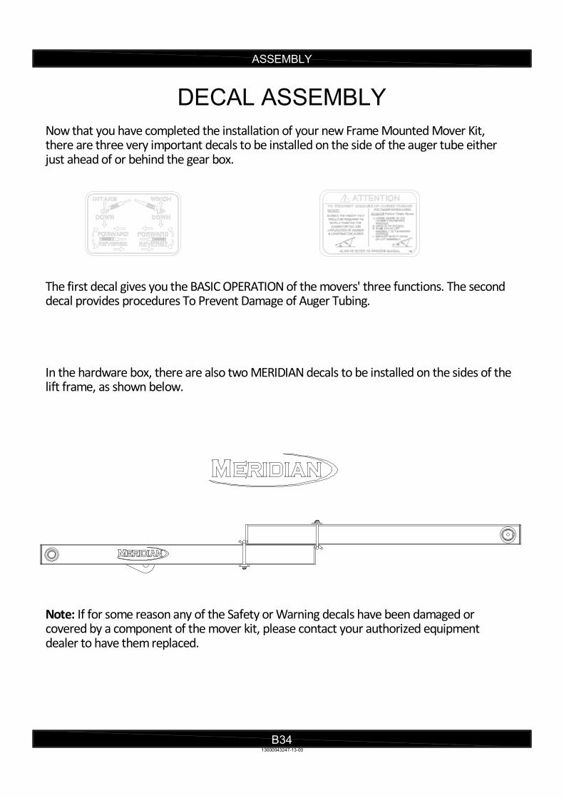
Now that you have completed the installation of your new Frame Mounted Mover Kit, there are three very important decals to be installed on the side of the auger tube either just ahead of or behind the gear box.
The first decal gives you the BASIC OPERATION of the movers' three functions. The second decal provides procedures To Prevent Damage of Auger Tubing. In the hardware box, there are also two MERIDIAN decals to be installed on the sides of thelift frame, as shown below.
Note: If for some reason any of the Safety or Warning decals have been damaged or covered by a component of the mover kit, please contact your authorized equipment dealer to have them replaced.
13000043247-13-00

PARTS
C1
WALKING BEAM
13000043247-14-00
1
34
13
2
5
7
8
9
10
11
12
16
17
19
20
21
23
24
6
18
22
14
15

Hex Cap Screw - 1/2-13 UNC - 1.25213-0702-080201
Brake213000042116-002
Hex Nut - 1/2213-0725-000083
Walking Beam w/ Bearings213000042605-004
Yoke - Castor213000042122-005
Spacer - Wheel Axle813000042594-006
Pin113000042119-007
Stop - Steering - Assembly113000042106-008
Washer - 1/2413-0735-000089
Bar - Steering113000042120-0010
Flat SAE Washer - 3/8213-0736-0000611
Stover - 3/8-16 213-0730-0000612
Spring Lock Washer - 1/2213-0734-0000813
NYLOCK NUT 3/8413-0729-0000614
HEX CAP SCREW 3/8 x 1 3/4-16413-0702-0602815
Hex Cap Screw - 3/8-16 UNC - 1.25213-0702-0602016
Link - Steering213000042121-0017
Yoke213000042108-0018
Washer - 3/4413-0735-0001219
Cotter Pin - 3/16 x 1 1/2413-0737-0604820
Kit - Rim c/w Tire413000042110-0021
Pin413000042114-0022
Hex Cap Screw - 1/2-13 UNC - 1.75213-0702-0802823
Washer213000042703-0024
C2
WALKING BEAM
PARTS
REF # PART # QUANTITY DESCRIPTION
FRAME MOUNT MOVER
13000043247-14-00
PARTS
C3
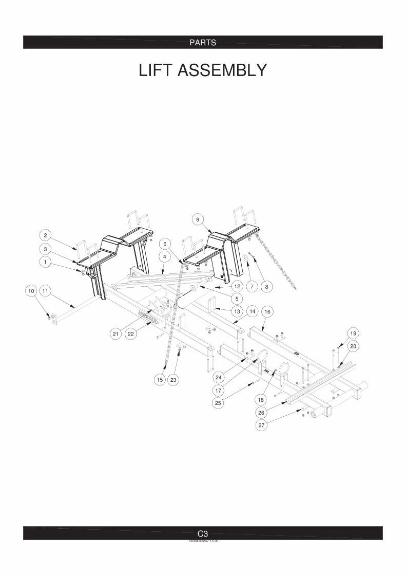
LIFT ASSEMBLY
21
2324
27
19
17
25
161413
10
2
3
1
9
5
4
15
6
12
22
87
18
13000043247-15-00
20
11
26
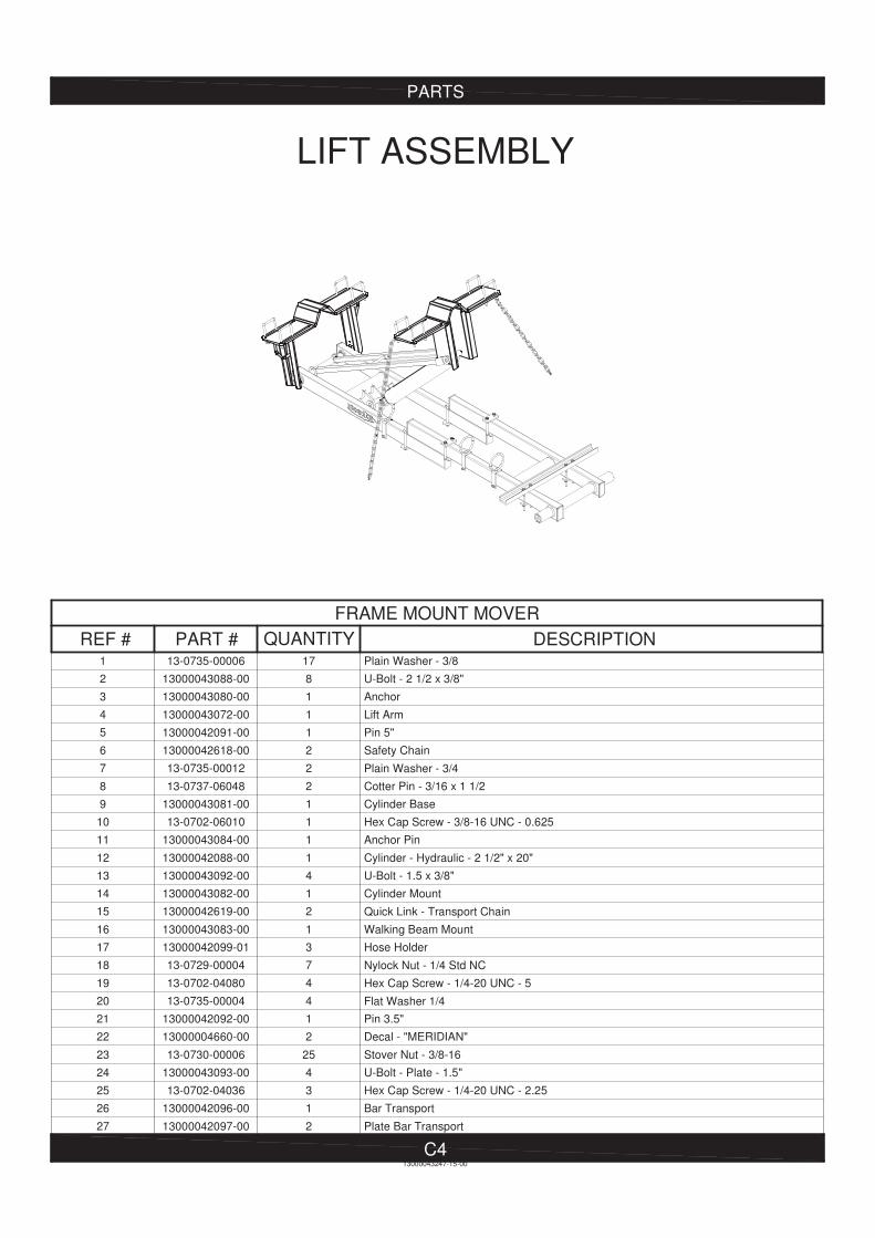
Plain Washer - 3/81713-0735-000061
U-Bolt - 2 1/2 x 3/8"813000043088-002
Anchor113000043080-003
Lift Arm113000043072-004
Pin 5"113000042091-005
Safety Chain213000042618-006
Plain Washer - 3/4213-0735-000127
Cotter Pin - 3/16 x 1 1/2213-0737-060488
Cylinder Base113000043081-009
Hex Cap Screw - 3/8-16 UNC - 0.625113-0702-0601010
Anchor Pin113000043084-0011
Cylinder - Hydraulic - 2 1/2" x 20"113000042088-0012
U-Bolt - 1.5 x 3/8"413000043092-0013
Cylinder Mount113000043082-0014
Quick Link - Transport Chain213000042619-0015
Walking Beam Mount113000043083-0016
Hose Holder313000042099-0117
Nylock Nut - 1/4 Std NC713-0729-0000418
Hex Cap Screw - 1/4-20 UNC - 5413-0702-0408019
Flat Washer 1/4413-0735-0000420
Pin 3.5"113000042092-0021
Decal - "MERIDIAN"213000004660-0022
Stover Nut - 3/8-16 2513-0730-0000623
U-Bolt - Plate - 1.5"413000043093-0024
Hex Cap Screw - 1/4-20 UNC - 2.25313-0702-0403625
Bar Transport113000042096-0026
Plate Bar Transport213000042097-0027
C4
LIFT ASSEMBLY
PARTS
REF # PART # QUANTITY DESCRIPTION
FRAME MOUNT MOVER
13000043247-15-00

Valve - Control c/w Fittings & Bypass LH113000042127-001
Handle Assembly113000042460-002
Hex Cap Screw - 5/16 x 1/2-18 313-0702-050403
Steering Column113000043246-004
6MP - Plug113000042139-005
Lift Bypass Valve113000042134-006
Fitting - Hydraulic - 6MP - 6MP90113000042138-007
6MP - 6MJ45 - Fitting - Hydraulic113000042137-008
Valve - Ball113000042136-009
6MP - 6FJX - 6 - Hose (Bypass)113000042142-0010
Block Cushion113000042186-0011
6MB - 6MJ45 - Fitting - Hydraulic613000042141-0012
8MB - 8MJ90 - Fitting - Hydraulic213000042140-0013
Nylon Locknut - 5/16313-0729-0000514
6MP - 8MB - Fitting113000042135-0015
Steering Column c/w Hydraulics113000042046-0016
PARTS
C5
STEERING COLUMN c/w HYDRAULICS
REF # PART # QUANTITY DESCRIPTION
FRAME MOUNT MOVER
13000043247-16-00
31
2
4
5
7
9
10
8
15
1413
1211
6
16

Hex Cap Screw 1/4 x 1-1/4-20113-0702-040201
1/4 " Flat Washer - Fender113-0735-100042
Hex Cap Screw - 1/2-13 UNC - 1.75113-0702-080283
Gear c/w Set Screws - Wheel113000042187-004
Gear113000042192-005
Socket Set Screw 5/16 x 3/8-18113-0742-050066
Hex Cap Screw - 3/8-16 UNC - 1413-0702-060167
Spring Lock Washer - 3/8413-0734-000068
Grip - Handle - 1.63" x 4"113000042196-009
Plate - Mount - Motor113000042191-0010
Motor113000042194-0011
Hex Nut 1/4-20113-0725-0000412
Hex Cap Screw - 1/2-13 UNC - 2113-0702-0803213
Plate Weld On c/w Hub & Spindle LH113000043071-0014
Flange Lock Nut 1/2-13213-0731-0000815
Washer SAE - 1/2313-0736-0000816
Spring113000042195-0017
Link113000042189-0018
Nylock Nut - 1/2 Std NC 313-0729-0000819
Bar113000042188-0020
PARTS
C6
DRIVE MOTOR - LH
REF # PART # QUANTITY DESCRIPTION
FRAME MOUNT MOVER
3
5 7
8 9 10
11
13
14
16
1817
19
13000043247-17-00
20
4
15
1 2
12
6
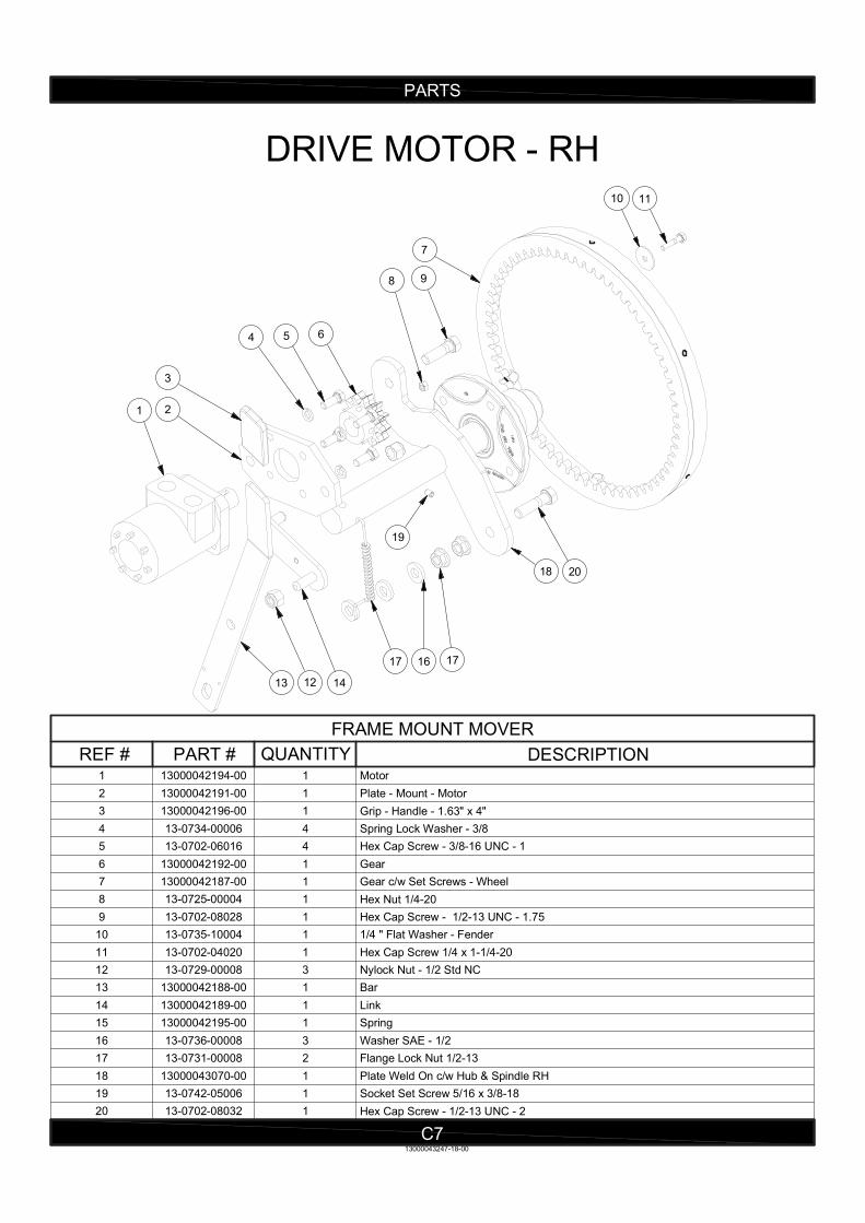
Motor113000042194-001
Plate - Mount - Motor113000042191-002
Grip - Handle - 1.63" x 4"113000042196-003
Spring Lock Washer - 3/8413-0734-000064
Hex Cap Screw - 3/8-16 UNC - 1413-0702-060165
Gear113000042192-006
Gear c/w Set Screws - Wheel113000042187-007
Hex Nut 1/4-20113-0725-000048
Hex Cap Screw - 1/2-13 UNC - 1.75113-0702-080289
1/4 " Flat Washer - Fender113-0735-1000410
Hex Cap Screw 1/4 x 1-1/4-20113-0702-0402011
Nylock Nut - 1/2 Std NC 313-0729-0000812
Bar113000042188-0013
Link113000042189-0014
Spring113000042195-0015
Washer SAE - 1/2313-0736-0000816
Flange Lock Nut 1/2-13213-0731-0000817
Plate Weld On c/w Hub & Spindle RH113000043070-0018
Socket Set Screw 5/16 x 3/8-18113-0742-0500619
Hex Cap Screw - 1/2-13 UNC - 2113-0702-0803220
PARTS
C7
DRIVE MOTOR - RH
REF # PART # QUANTITY DESCRIPTION
FRAME MOUNT MOVER
5
3
4
21
17
13 12
16
18 20
9
14
6
13000043247-18-00
7
17
8
10 11
19
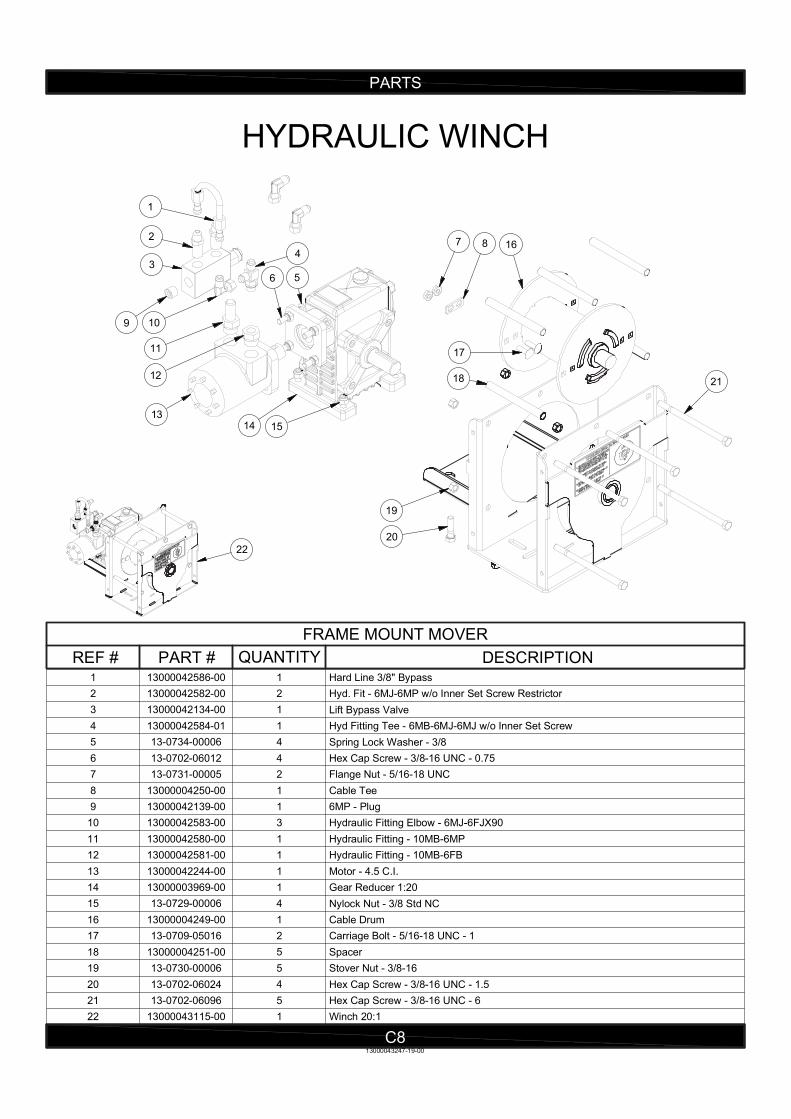
Hard Line 3/8" Bypass113000042586-001
Hyd. Fit - 6MJ-6MP w/o Inner Set Screw Restrictor213000042582-002
Lift Bypass Valve113000042134-003
Hyd Fitting Tee - 6MB-6MJ-6MJ w/o Inner Set Screw113000042584-014
Spring Lock Washer - 3/8413-0734-000065
Hex Cap Screw - 3/8-16 UNC - 0.75413-0702-060126
Flange Nut - 5/16-18 UNC 213-0731-000057
Cable Tee113000004250-008
6MP - Plug113000042139-009
Hydraulic Fitting Elbow - 6MJ-6FJX90313000042583-0010
Hydraulic Fitting - 10MB-6MP113000042580-0011
Hydraulic Fitting - 10MB-6FB113000042581-0012
Motor - 4.5 C.I.113000042244-0013
Gear Reducer 1:20113000003969-0014
Nylock Nut - 3/8 Std NC 413-0729-0000615
Cable Drum113000004249-0016
Carriage Bolt - 5/16-18 UNC - 1213-0709-0501617
Spacer513000004251-0018
Stover Nut - 3/8-16 513-0730-0000619
Hex Cap Screw - 3/8-16 UNC - 1.5413-0702-0602420
Hex Cap Screw - 3/8-16 UNC - 6513-0702-0609621
Winch 20:1113000043115-0022
PARTS
C8
HYDRAULIC WINCH
REF # PART # QUANTITY DESCRIPTION
FRAME MOUNT MOVER
20
14
56
13
1
2
43
9 10
11
12
15
22
13000043247-19-00
19
7 8
18
16
17
21

PARTS
C9
PUMP TANK AND FILTER
13000043247-20-00
43
56
2
1
11
17
10
8
1314
1516
18
19
9
20
21
22
23
7
12
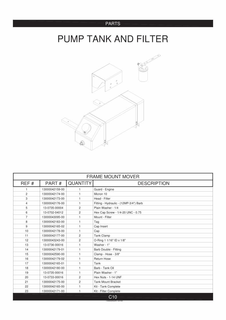
Guard - Engine113000042159-001
Micron 10113000042174-002
Head - Filter113000042173-003
Fitting - Hydraulic - (12MP-3/4") Barb113000042176-004
Plain Washer - 1/4213-0735-000045
Hex Cap Screw - 1/4-20 UNC - 0.75213-0702-040126
Mount - Filter113000043095-007
Tag113000042183-008
Cap Insert113000042165-029
Cap113000042178-0010
Tank Clamp213000042177-0011
O-Ring 1 1/16" ID x 1/8" 213000043243-0012
Washer - 1"113-0736-0001613
Barb Double - Fitting 113000042179-0114
Clamp - Hose - 3/8"113000042590-0015
Return Hose113000042179-0216
Tank113000042165-0117
Barb - Tank Oil 113000042180-0018
Plain Washer - 1"113-0735-0001619
Hex Nuts - 1-14 UNF213-0733-0001620
Tank Mount Bracket213000042175-0021
Kit - Tank Complete113000042165-0022
Kit - Filter Complete113000042171-0023
13000043247-20-00
C10
PUMP TANK AND FILTER
PARTS
REF # PART # QUANTITY DESCRIPTION
FRAME MOUNT MOVER
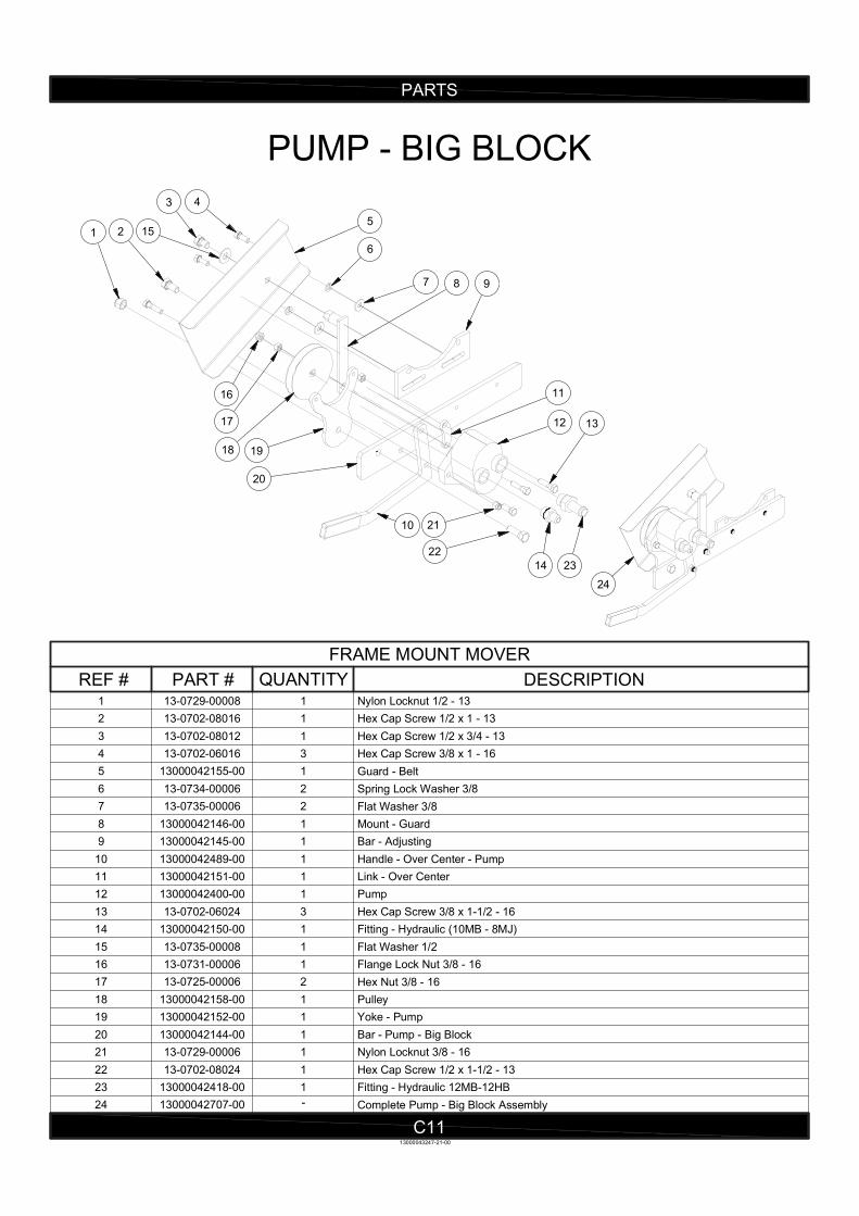
Nylon Locknut 1/2 - 13113-0729-000081
Hex Cap Screw 1/2 x 1 - 13113-0702-080162
Hex Cap Screw 1/2 x 3/4 - 13113-0702-080123
Hex Cap Screw 3/8 x 1 - 16313-0702-060164
Guard - Belt113000042155-005
Spring Lock Washer 3/8213-0734-000066
Flat Washer 3/8213-0735-000067
Mount - Guard113000042146-008
Bar - Adjusting113000042145-009
Handle - Over Center - Pump113000042489-0010
Link - Over Center113000042151-0011
Pump 113000042400-0012
Hex Cap Screw 3/8 x 1-1/2 - 16313-0702-0602413
Fitting - Hydraulic (10MB - 8MJ)113000042150-0014
Flat Washer 1/2113-0735-0000815
Flange Lock Nut 3/8 - 16113-0731-0000616
Hex Nut 3/8 - 16213-0725-0000617
Pulley113000042158-0018
Yoke - Pump113000042152-0019
Bar - Pump - Big Block113000042144-0020
Nylon Locknut 3/8 - 16113-0729-0000621
Hex Cap Screw 1/2 x 1-1/2 - 13113-0702-0802422
Fitting - Hydraulic 12MB-12HB113000042418-0023
Complete Pump - Big Block Assembly-13000042707-0024
PARTS
C11
PUMP - BIG BLOCK
REF # PART # QUANTITY DESCRIPTION
FRAME MOUNT MOVER
1 2
3 4
6
7 98
5
12 13
18 19
22
21
11
20
10
2314
16
17
15
13000043247-21-00
24
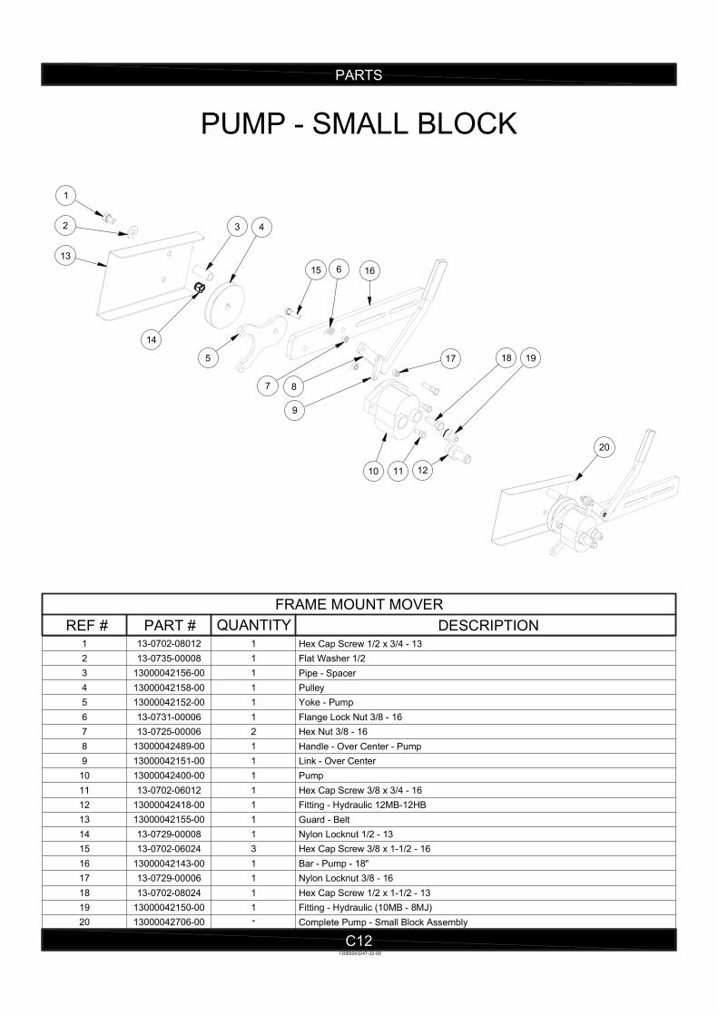
Hex Cap Screw 1/2 x 3/4 - 13113-0702-080121
Flat Washer 1/2113-0735-000082
Pipe - Spacer113000042156-003
Pulley113000042158-004
Yoke - Pump113000042152-005
Flange Lock Nut 3/8 - 16113-0731-000066
Hex Nut 3/8 - 16213-0725-000067
Handle - Over Center - Pump113000042489-008
Link - Over Center113000042151-009
Pump 113000042400-0010
Hex Cap Screw 3/8 x 3/4 - 16113-0702-0601211
Fitting - Hydraulic 12MB-12HB113000042418-0012
Guard - Belt113000042155-0013
Nylon Locknut 1/2 - 13113-0729-0000814
Hex Cap Screw 3/8 x 1-1/2 - 16313-0702-0602415
Bar - Pump - 18"113000042143-0016
Nylon Locknut 3/8 - 16113-0729-0000617
Hex Cap Screw 1/2 x 1-1/2 - 13113-0702-0802418
Fitting - Hydraulic (10MB - 8MJ)113000042150-0019
Complete Pump - Small Block Assembly-13000042706-0020
PARTS
C12
PUMP - SMALL BLOCK
REF # PART # QUANTITY DESCRIPTION
FRAME MOUNT MOVER
1
2
13
14
15
4
5
166
7 8
17
9
10
18
11
19
12
13000043247-22-00
20
3
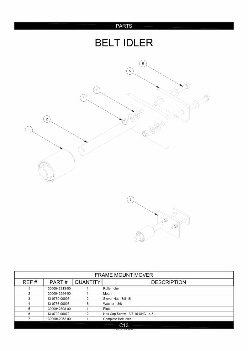
Roller Idler113000042313-001
Mount113000042554-002
Stover Nut - 3/8-16 213-0730-000063
Washer - 3/8613-0736-000064
Plate113000042308-005
Hex Cap Screw - 3/8-16 UNC - 4.5213-0702-060726
Complete Belt Idler113000042052-007
PARTS
C13
BELT IDLER
13000043247-23-00
REF # PART # QUANTITY DESCRIPTION
FRAME MOUNT MOVER
6
5
4
3
2
1
7
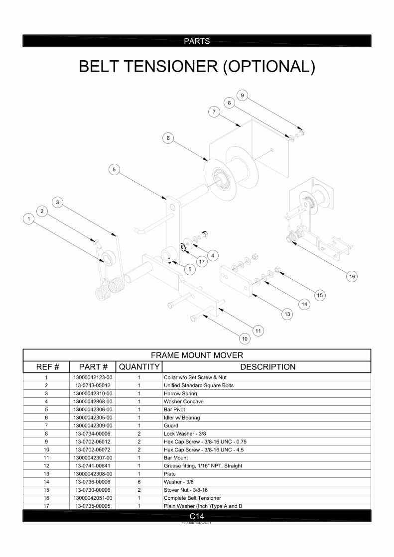
Collar w/o Set Screw & Nut113000042123-001
Unified Standard Square Bolts113-0743-050122
Harrow Spring113000042310-003
Washer Concave113000042868-004
Bar Pivot113000042306-005
Idler w/ Bearing113000042305-006
Guard113000042309-007
Lock Washer - 3/8213-0734-000068
Hex Cap Screw - 3/8-16 UNC - 0.75213-0702-060129
Hex Cap Screw - 3/8-16 UNC - 4.5213-0702-0607210
Bar Mount113000042307-0011
Grease fitting, 1/16" NPT, Straight113-0741-0064112
Plate113000042308-0013
Washer - 3/8613-0736-0000614
Stover Nut - 3/8-16213-0730-0000615
Complete Belt Tensioner113000042051-0016
Plain Washer (Inch )Type A and B113-0735-0000517
PARTS
C14
BELT TENSIONER (OPTIONAL)
REF # PART # QUANTITY DESCRIPTION
FRAME MOUNT MOVER
7
6
5
4
3
10
11
13
14
15
9
8
16
5
13000043247-24-01
2
1
17
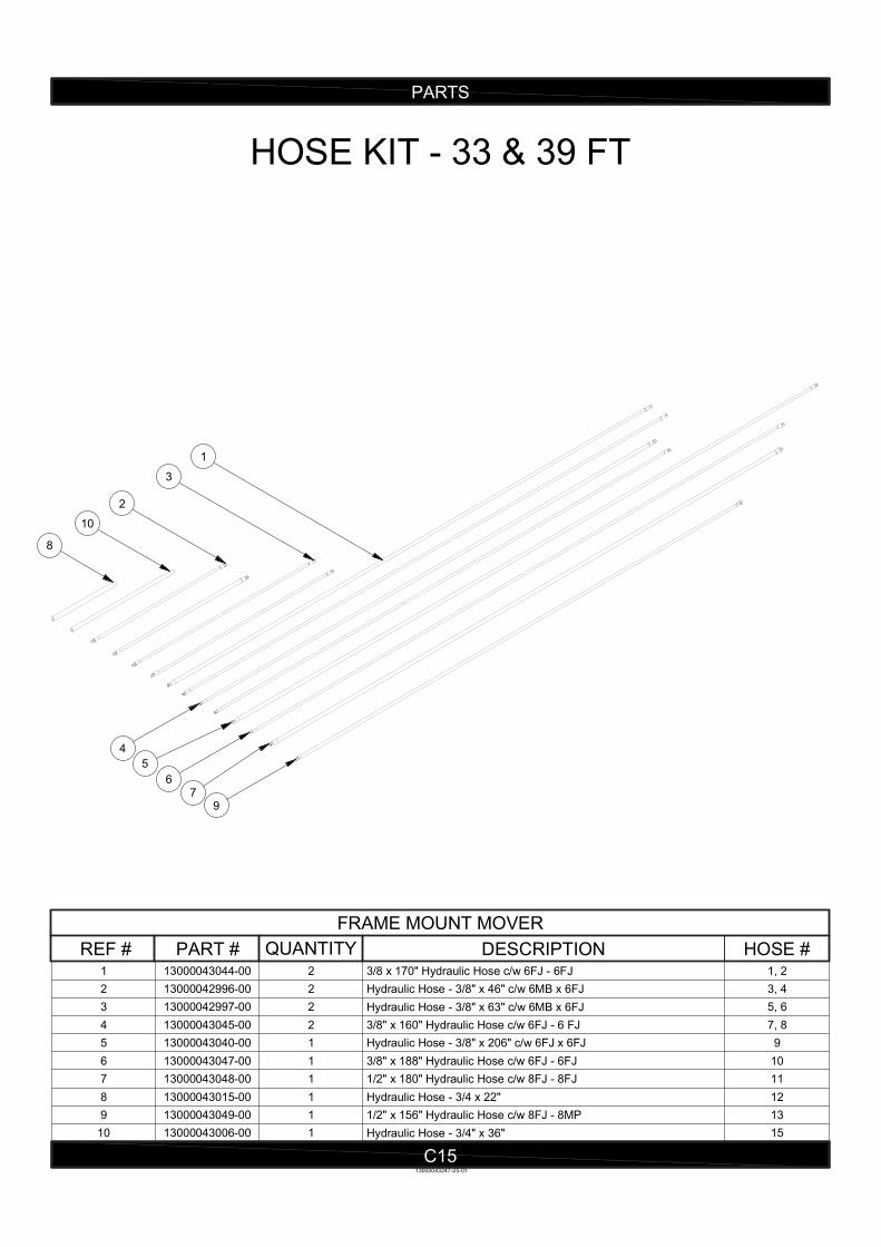
1, 23/8 x 170" Hydraulic Hose c/w 6FJ - 6FJ213000043044-001
3, 4Hydraulic Hose - 3/8" x 46" c/w 6MB x 6FJ213000042996-002
5, 6Hydraulic Hose - 3/8" x 63" c/w 6MB x 6FJ213000042997-003
7, 83/8" x 160" Hydraulic Hose c/w 6FJ - 6 FJ213000043045-004
9Hydraulic Hose - 3/8" x 206" c/w 6FJ x 6FJ113000043040-005
103/8" x 188" Hydraulic Hose c/w 6FJ - 6FJ113000043047-006
111/2" x 180" Hydraulic Hose c/w 8FJ - 8FJ113000043048-007
12Hydraulic Hose - 3/4 x 22"113000043015-008
131/2" x 156" Hydraulic Hose c/w 8FJ - 8MP113000043049-009
15Hydraulic Hose - 3/4" x 36"113000043006-0010
PARTS
C15
HOSE KIT - 33 & 39 FT
REF # PART # QUANTITY DESCRIPTION
FRAME MOUNT MOVER
HOSE #
8
10
2
3
1
4
5
67
9
13000043247-25-01
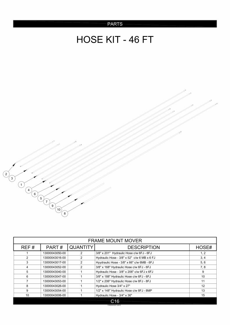
1, 23/8" x 201" Hydraulic Hose c/w 6FJ - 6FJ213000043050-001
3, 4Hydraulic Hose - 3/8" x 52" c/w 6 MB x 6 FJ213000043016-002
5, 6Hyydraulic Hose - 3/8" x 66" c/w 6MB - 6FJ213000043017-003
7, 83/8" x 168" Hydraulic Hose c/w 6FJ - 6FJ213000043052-004
9Hydraulic Hose - 3/8" x 206" c/w 6FJ x 6FJ113000043040-005
103/8" x 188" Hydraulic Hose c/w 6FJ - 6FJ113000043047-006
111/2" x 206" Hydraulic Hose c/w 8FJ - 8FJ113000043053-007
12Hydraulic Hose 3/4" x 27"113000043026-008
131/2" x 148" Hydraulic Hose c/w 8FJ - 8MP113000043054-009
15Hydraulic Hose - 3/4" x 36"113000043006-0010
PARTS
C16
HOSE KIT - 46 FT
REF # PART # QUANTITY DESCRIPTION
FRAME MOUNT MOVER
HOSE#
2
3
1
4
6
5
9
10
7
8
13000043247-26-01
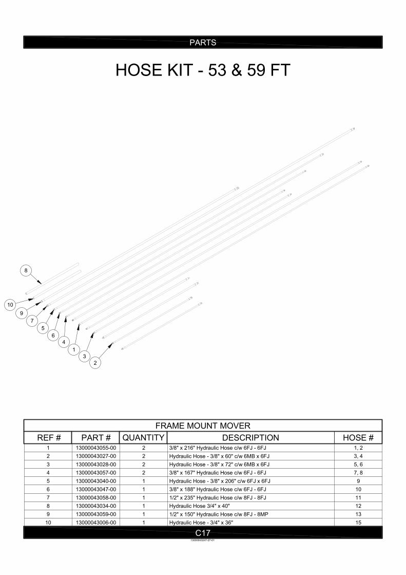
1, 23/8" x 216" Hydraulic Hose c/w 6FJ - 6FJ213000043055-001
3, 4Hydraulic Hose - 3/8" x 60" c/w 6MB x 6FJ213000043027-002
5, 6Hydraulic Hose - 3/8" x 72" c/w 6MB x 6FJ213000043028-003
7, 83/8" x 167" Hydraulic Hose c/w 6FJ - 6FJ213000043057-004
9Hydraulic Hose - 3/8" x 206" c/w 6FJ x 6FJ113000043040-005
103/8" x 188" Hydraulic Hose c/w 6FJ - 6FJ113000043047-006
111/2" x 235" Hydraulic Hose c/w 8FJ - 8FJ113000043058-007
12Hydraulic Hose 3/4" x 40"113000043034-008
131/2" x 150" Hydraulic Hose c/w 8FJ - 8MP113000043059-009
15Hydraulic Hose - 3/4" x 36"113000043006-0010
PARTS
C17
HOSE KIT - 53 & 59 FT
REF # PART # QUANTITY DESCRIPTION
FRAME MOUNT MOVER
HOSE #
8
10
9
7
5
6
4
1
3
2
13000043247-27-01
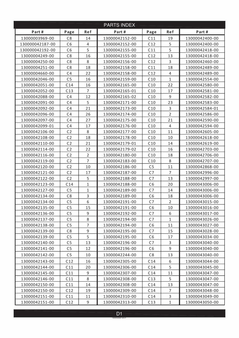
PARTS INDEX
D113000043247-28-01
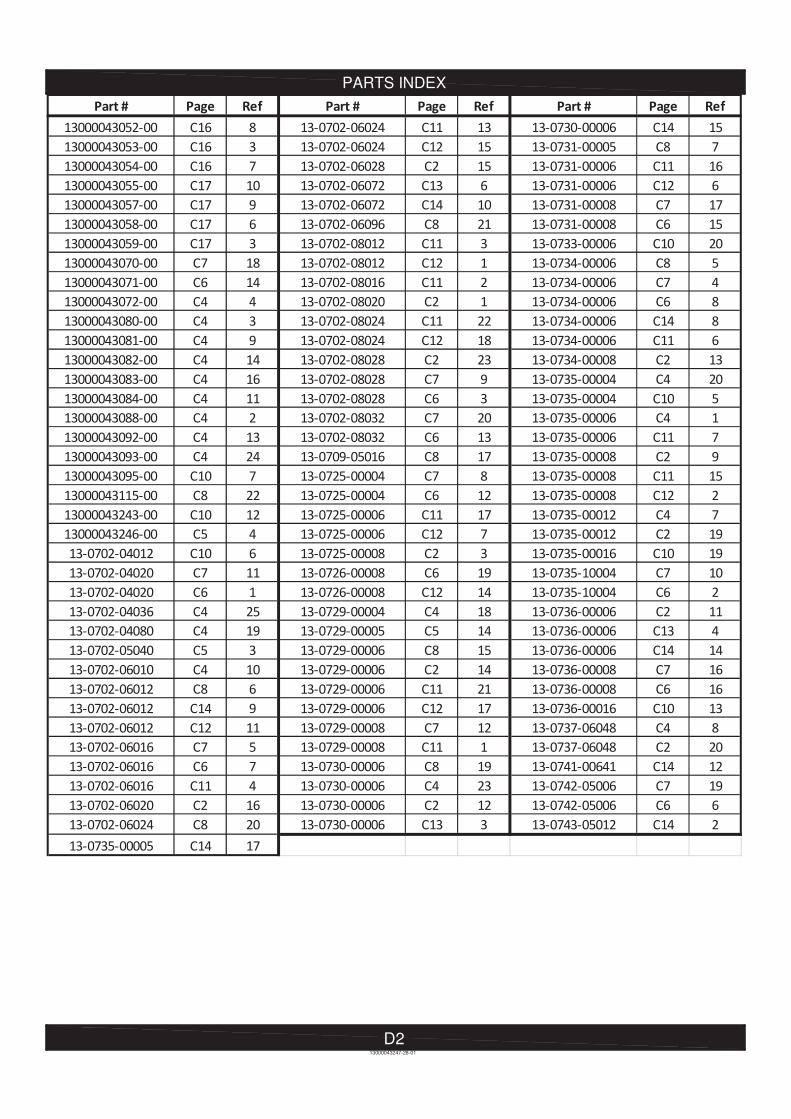
PARTS INDEX
13000043247-28-01
D2
WARRANTY
E1
Limited Warranty Statement
1. Meridian Manufacturing Inc warrants each new Meridian Manufacturing Inc product (the "Goods") to be free from defects in material and workmanship under normal use and service for a period of two (2) years or ninety (90) days in the case of commercial use, from the shipment date from the Meridian dealer (FCA). 2. Meridian warrants replacement parts and components either manufactured or sold by, will be free from defects in materials or workmanship under normal use and service for thirty (30) days from the shipment date from the Meridian dealer (FCA), or the remainder of the original warranty period on the Goods, whichever is longer. 3. This warranty does not apply to: a) to any merchandise or components thereof, which in the sole and unfettered opinion of Meridian, have been subject to misuse, unauthorized modifications, alteration, accident, negligence, product abuse or lack of required maintenance. b) if repairs have been made with parts or by persons other than those parts or persons approved by Meridian.c) to parts and accessories not manufactured by Meridian including, but not limited to, engines, batteries, tires, belts, PTO shafts or other trade accessories. Such parts shall be covered by the warranty given by the actual manufacturer, if any.d) to failure of parts; or failure of parts to perform due to wear under normal or excessive service conditions; or to failure due to use by the Purchaser for purposes other than originally intended at time of manufacture, including without limitation using the Goods for mixing fertilizer, etc.; or used in excess of the built specifications. e) to Goods used in areas exposed to corrosive or aggresive conditions including, but not limited to, salt water from either inside or outside the Goods.f) to failures or defects arising out of damage during shipment or during storage.g) to materials replaced or repaired under this warranty, except to the extent of the remainder of the applicable warranty. 4. The obligation of Meridian under this warranty shall not arise unless Meridian is notified and this warranty is presented together with a written statement specifying the claim or defect within thirty (30) days after the failure is first detected or made known to the Purchaser and within: (i) two (2) years, or ninety (90) days in the case of commercial use; or (ii) thirty (30) days in the case of replacement parts and components manufactured by Meridian; from the shipment date from the Meridian dealer (FCA). Meridian in its sole and unfettered discretion shall determine if the claim is valid and whether correction of the defect or failure shall be made by repair or replacement of the materials. 5. Title to any replaced materials Meridian wishes to have pass to it, shall pass to Meridian. 6. The obligation of Meridian hereunder extends only to the original Purchaser or Buyer to whom the Goods were initially sold. This warranty shall not be subject to any assignment or transfer without the written consent of Meridian. 7. The purchaser acknowledges that it has made its own independent decision to approve the use of the Goods and also the specific fabrication and construction procedures utilized to complete the Goods, and has satisfied itself as to the suitability of these products for its use.
13000004273-11-02

WARRANTY
E2
8. This warranty is subject to the following limitations, provisions and conditions: a) Meridian shall have no liability hereunder for any claims, including field re-work.b) Meridian shall not be liable for any incidental loss or damage, however caused, including, without limitation, normal wear and tear.c) Meridian makes no express or implied warranties of any nature whatsoever except for such express warranties as set out herein. The warranty provided herein is in lieu of and excludes all other warranties, guarantees or conditions pertaining to the Goods, written or oral, statutory, express or implied, (except the warranty as to title) including any warranty as to the merchantability or fitness for any particular purpose. Meridian expressly disclaims all other representations, conditions or warranties, expressed or implied, statutory or otherwise and any representations, warranties or conditions that may arise from a course of dealing or usage of trade. The warranty provided herein shall constitute Meridian's sole obligation and liability and the Purchaser's sole remedy for breach of warranty. No other warranty has been made by any employee, agent, or representative of Meridian and any statements contained in any other printed material of Meridian is expressly excluded herefrom. Meridian shall not be responsible for any warranty offered by the Purchaser to its customers with respect to the Goods and the Purchaser shall indemnify Meridian with respect to same if any of those customers makes a claim against Meridian relating to any such warranty.d) Subject to Meridian's obligations contained in paragraphs 1 and 2 herein, none of Meridian, its officers, directors, servants or agents shall be liable, or responsible for any loss or damage (including strict liability and liability for loss or damage due to items which the manufacturing processes are designed to identify) whether such loss or damage is caused by negligence in any manner whatsoever (including gross negligence, error, misrepresentation, misstatement, imprudence, lack of skill or lack of judgement). 9. The sole financial obligation of Meridian under this warranty shall be limited to the repair or replacement of the Goods as originally supplied and in no event shall they exceed the original cost of the Goods supplied. 10. Meridian shall not have any obligation under any warranty herein until all accounts have been paid in full by the Purchaser. 11. The construction and interpretation of this Warranty shall be governed by the laws of the Province of Saskatchewan. Warranty Claim Procedure 1. Purchaser must register the Goods with Meridian.2. Purchaser must contact the dealer where the unit was purchased from upon discovery of any defects.3. A completed warranty claim form must be submitted by the dealer to Meridian's warranty representative for review and any subsequent course of action.4. Warranty repair work will only be performed by Meridian or an approved representative of Meridian. No warranty work completed prior to approval by Meridian will be honored. Failure to follow procedure may affect any or all of this warranty.5. Claims will be adjudicated at the sole discretion of Meridian and in accordance with the terms and conditions of the limited warranty.
13000004273-12-01

MERIDIAN MANUFACTURING INC. With over 65 years of experience,
Meridian is your storage and handling expert.
© 2014 Meridian Manufacturing Inc. Registered Trademarks Used Under License. Printed in Canada (12/14)
Winkler Office
Box 760, 275 Hespler Ave.
Winkler, MB R6W 4A8
PH: 204.325.7883
TF: 800.665.7259
FX: 204.325.5556
Storm Lake Office
2902 Expansion Blvd.
Storm Lake, IA 50588
PH: 712.732.1780
TF: 800.437.2334
FX: 712.732.1028
Lethbridge Office
3125 - 24 Ave. N.
Lethbridge, AB T1H 5G2
PH: 403.320.7070
TF: 800.661.1436
FX: 403.320.7579
Regina Office
PO Box 1996
Regina, SK S4P 3E1
PH: 306.545.4044
TF: 800.667.5904
FX: 306.545.4216
Camrose Office
4232 - 38 St.
Camrose, AB T4V 4B2
PH: 780.672.4516
TF: 800.830.2467
FX: 780.672.4759
MERIDIAN MANUFACTURING INC. With over 65 years of experience,
Meridian is your storage and handling expert.
Cambridge Office
605 Sheldon Dr.
Cambridge, On. N1T 2K1
PH: 519.620.6004
TF: 855.346.3712
FX: 519.620.6041
®
www.meridianmfg.com