asme sec viii d3 part kd-8.pdf
TRANSCRIPT
ARTICLE KD-8SPECIAL DESIGN REQUIREMENTS FOR LAYERED
VESSELS
KD-800 GENERAL
(a) For the purposes of this Division, alayered vesselis defined as any cylindrical or spherical vessel thatis constructed of two or more concentric, hollow cylin-ders or spheres assembled in such a way that the outersurface of each cylinder or sphere is in contact withthe inner surface of the next larger cylinder or sphere.Each individual cylinder or sphere is referred to asa layer.
(b) There are three types of layered vessel construc-tions considered in this Article:
(1) vessels made of forged, machined layers thatare shrink-fitted together;
(2) vessels made of rolled, welded, and machinedlayers that are shrink-fitted together;
(3) vessels made of concentrically wrapped andwelded layers.
(c) This Article addresses layers and inner shells(see KD-104) that are considered in the static strengthof the vessels. Liners are not considered in the staticstrength of vessels and shall meet the requirements ofKD-103.
KD-801 Design Criteria
(a) The static strength of layered vessels with nosignificant gaps between the layers, those that meetthe requirements of KD-810, or those for whichQc p1 (see KD-822 and KD-824) shall be determined inaccordance with Articles KD-1 and KD-2.
(b) The equations given in this Article are based onelastic analysis. However, in the case of shrunk fitvessels, if additional prestressing is obtained from auto-frettage, the residual stress distribution from the localplastic deformation shall be calculated in accordancewith the rules of Article KD-5. In determining the finalresidual stress distribution using an autofrettaged liner,the nonlinear effects of the Bauschinger effect shallbe considered.
74
(c) The beneficial residual stress distribution in ves-sels assembled by shrink fitting shall be calculatedaccording to the rules given in KD-810. For weldedlayer shrink-fit vessel construction, the beneficial effectsfrom the residual stress shall only be considered inthe Article KD-3 and KD-4 analysis in areas of thevessel not located in a weld or a heat-affected zoneof a weld.
(d) Concentrically wrapped, welded, layered vesselsshall be treated as monobloc vessels except that theradial and circumferential stresses shall be calculatedwith corrections for the effects of the gaps betweenthe layers. Rules for calculating these stresses are givenin KD-820. No beneficial effects from compressiveresidual stresses shall be considered in the fatigueanalysis of these types of vessels.
KD-802 Nomenclature
Dp diameter at any point in the wall, in.DIp diameter of inside surface of innermost layer, in.Dif p diameter of the interface between layersDnp diameter of outside surface of layern, in.DOp diameter of outside surface of outermost
layer, in.Ep elastic modulus, psiEIp elastic modulus of inner layer, psiEnp elastic modulus of thenth layer, psiEOp elastic modulus of outer layer, psiFcp calculated factor for circumferential expansion
of permissible layer gapsKp layer number that diameterD is withinNp total number of layersPp pressure, psig
Pif p interface pressure between shrunk fit layers, psiPnp pressure between layersn andn + 1, caused by
layer interference, psiPtp internal test pressure, psigQcp ratio of the measured circumferential displace-
COPYRIGHT American Society of Mechanical EngineersLicensed by Information Handling ServicesCOPYRIGHT American Society of Mechanical EngineersLicensed by Information Handling Services
01
KD-802 PART KD — DESIGN REQUIREMENTS KD-811.2
ment at hydrotest to the calculated value of avessel with zero gaps
Yp DO/DI
Yip ratio of outside diameter to inside diameter ofinner layer
Yop ratio of outside diameter to inside diameter ofouter layer
emp actual circumferential growth, in., to be mea-sured at the hydrotest pressure as specified inKD-822 and KD-824
ethp theoretical circumferential growth, in.np layer number in which stresses are to be calcu-
latedtp total thickness, in.
tnp thickness of layern, in.dp diametrical interference between inner and
outer layers, for two-piece shrink-fit vesselsonly, in.
dnp diametrical interference between layersn andn + 1, in.
np Poisson’s rationip Poisson’s ratio for inner layernop Poisson’s ratio for outer layersrp radial stress component at radiusr, psi
srrp radial residual stresses, psistp tangential stress component at radiusr, psi
strp tangential residual stresses, psi
NOTE: Any consistent system of units may be used.
KD-810 RULES FOR SHRINK-FITLAYERED VESSELS
(a) This type of construction differs from concentri-cally wrapped and welded layers in that each layeris fabricated individually and machined to cause aninterference pressure to exist in the assembled layeredvessel. The manufacture and assembly of the cylindricallayers shall be accomplished so that the interferencestress distribution in all layers can be determined within±10%. Documentation of the manufacturing and assem-bly process shall be reviewed by the ProfessionalEngineer who signs the Manufacturer’s Design Reportso that the actual stress distribution in the completedvessel can be verified.
(b) The final residual stress shall be calculated andshall not exceed the yield strength in any layer at anydiameter for the interference fit condition except in thecase of autofrettaged liners [see KD-810(c)].
(c) Residual stresses from the interference fittingoperation shall be combined with other residual stressesfrom other manufacturing or assembly operations in
75
the layers or completed vessel. See KD-801(a) and (b).Plastic analysis in accordance with KD-240 may alsobe used.
(d) Any reduction in yield strength or relaxation in theresidual stress distribution due to elevated temperaturesduring the shrink fitting operation or as a result ofwelding shall be considered.
(e) Rules for vessels constructed from two layersare given in KD-811 and rules for vessels constructedof more than two layers are given in KD-812.
KD-811 Construction With Only Two Layers
KD-811.1 Interference Pressure.The interferencepressure between the inner and outer layers is calculatedas follows:
Pif pd
Dif A
where
A p1Ei 1D
2I + D2
if
D2if − D2
I
− ni2 +1
EO 1D2if + D2
O
D2O − D2
if
+ nO2
This analysis assumes that there is no longitudinalforce transmitted between the inner and outer cylinderdue to friction at the interface. In some cases of shrinkfit, longitudinal stresses can be developed which willaffect the interface pressure obtained due to the Poissoneffect. For such cases, a more detailed analysis isrequired to determine the residual stresses.
KD-811.2 Residual Shrink-Fit Stresses.The resid-ual stresses at any point removed from discontinuitiesin the inner layer,DI ≤ D ≤ Dif , are then calculatedfrom Eqs. (1) and (2):
str p −PifY
2i
Y2i − 1 11 +
D2I
D22 (1)
srr p −PifY
2i
Y2i − 1 11 −
D2I
D22 (2)
and in the outer layer,Dif ≤ D ≤ DO, from Eqs. (3)and (4):
COPYRIGHT American Society of Mechanical EngineersLicensed by Information Handling ServicesCOPYRIGHT American Society of Mechanical EngineersLicensed by Information Handling Services
KD-811.2 2001 SECTION VIII — DIVISION 3 KD-812
str pPif
Y2o − 1 11 +
D2O
D22 (3)
srr pPif
Y2o − 1 11 −
D2O
D22 (4)
where
Yi p Dif /DI
Yo p DO/Dif
KD-811.3 Final Distribution of Residual Stresses.If the vessel components contain known residual stressesproduced by autofrettage prior to assembly, these resid-ual stresses shall be combined with the stresses deter-mined from Eqs. (1) through (4) above to determinethe final distribution of residual stresses after assembly;see KD-801(a) and (b).
KD-812 Construction With More Than TwoLayers
For the case of vessels composed of more thantwo layers assembled with interference, the followingprocedure shall be used.
(a) Assemble the first two layers and calculate theresidual stresses as in KD-811.
(b) Determine the interference between this assemblyand the next layer and calculate the resulting residualstresses as if the first two layers were a single layer.If the first two layers do not have the same elasticmodulus, then an appropriate composite value shallbe used.
(c) Add the stresses calculated in KD-812(b) to thosecalculated in KD-812(a) and determine the total residualstress distribution in the resulting assembly. This proce-dure may be repeated for any number of successivelayers.
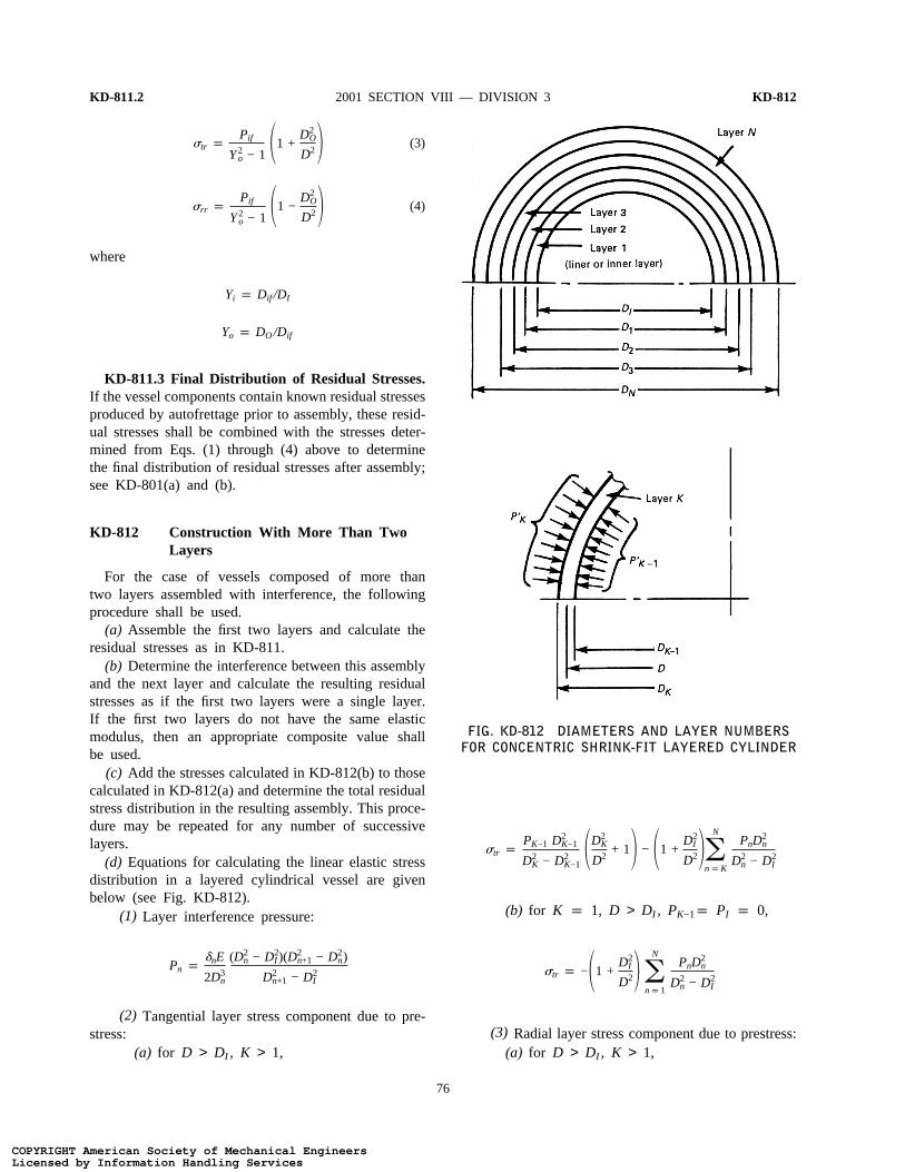
(d) Equations for calculating the linear elastic stressdistribution in a layered cylindrical vessel are givenbelow (see Fig. KD-812).
(1) Layer interference pressure:
Pn pdnE
2D3n
(D2n − D2
I )(D2n+1 − D2
n)
D2n+1 − D2
I
(2) Tangential layer stress component due to pre-stress:
(a) for D > DI , K > 1,
76
FIG. KD-812 DIAMETERS AND LAYER NUMBERSFOR CONCENTRIC SHRINK-FIT LAYERED CYLINDER
str pPK−1 D2
K−1
D2K − D2
K−11D2
K
D2+ 12 − 11 +
D2I
D22oN
npK
PnD2n
D2n − D2
I
(b) for K p 1, D > DI , PK−1p PI p 0,
str p −11 +D2
I
D22 oN
np1
PnD2n
D2n − D2
I
(3) Radial layer stress component due to prestress:(a) for D > DI , K > 1,
COPYRIGHT American Society of Mechanical EngineersLicensed by Information Handling ServicesCOPYRIGHT American Society of Mechanical EngineersLicensed by Information Handling Services
KD-812 PART KD — DESIGN REQUIREMENTS KD-824
srr p −PK−1D
2K−1
D2K − D2
K−11D2
K
D2− 12 − 11 −
D2I
D22 oN
npK
PnD2n
D2n − D2
I
(b) for K p 1, D > DI , PK−1 p PI p 0,
srr p − 11 −D2
I
D22 oN
np1
PnD2n
D2n − D2
I
KD-820 RULES FOR CONCENTRICALLYWRAPPED AND WELDEDLAYERED VESSELS
KD-821 Welded Layers
The rules given in KD-820 are valid only if KD-821(a) through (d) are met.
(a) Each layer shall have an outer diameter to innerdiameter ratio no greater than 1.10 and a minimumlayer thickness of1⁄4 in. (6 mm).
(b) All layers in a vessel shall have the same modulusof elasticity and Poisson’s ratio over the design tempera-ture range.
(c) No beneficial effects from prestress can be takeninto account in the fatigue analysis of the vessel.
(d) The effects of gaps between layers on the stressdeveloped in the layers shall be considered in the stressanalysis of the vessel; see KD-822 through KD-825.
KD-822 Circumferential Expansion ofCylindrical Layers
When a layered cylindrical shell is pressurized, theoutside circumference will not expand as much as amonobloc vessel of the same dimensions unless alllayers are in intimate contact with each other. A measureof the extent of the gaps between layers is to calculatethe circumferential expansioneth [see Eq. (1)] of amonobloc cylindrical shell of the same dimensions andcompare that to the actual measured circumferentialexpansionem of the layered vessel. This is done atthe hydrotest pressure. The ratio of the actual expansionduring hydrotest, divided by the theoretical elasticexpansion during hydrotest is denoted asQc [seeEq. (2)].
eth pPt (2 − n)pDO
E(Y2 − 1)(1)
The designer may perform a more rigorous analysis tocalculateeth, considering end effects and constraint.
77
Qc pem
eth(2)
Qc shall be between 0.5 and 1.0; see KF-827.
KD-823 Calculation of Stresses in CylindricalShells
The designer shall assume a value ofQc between0.5 and 1.0 to determine the stress distribution in thevessel. The actual value ofQc measured at hydrotestshall be reported to the designer to verify that thevessel meets the rules of this Division. Assuming avalue of Qc, or using the measured value ofQc, thevalue of Fc, the gap correction factor, is calculatedusing Eq. (1):
Fc p2PD2
I (1.0 − Qc)
D2O − D2
I
(1)
Once the value ofFc is known for a particular vessel,the three principal stresses due to internal pressure arecalculated according to Eqs. (2), (3), and (4). Thesecalculated stresses are primary membrane stresses usedin KD-220, and in place of those calculated in KD-260 for a monobloc vessel, and must meet the require-ments of KD-230.
st pPD2
I (D2O + D2)
D2(D2O − D2
I )+ Fc
DO + DI − 2DDO − DI
(2)
sr p1D 5−PDI +
PD2I
D2O − D2
I3D − DI − D2
O 11D
−1DI24
+Fc
DO − DI[D(DI + DO) − D2 − DODI]6 (3)
sL pPD2
I
D2O − D2
I
(4)
KD-824 Circumferential Expansion of WeldedLayered Spherical Shells andHemispherical Heads
The theoretical circumferential expansion of a spheri-cal shell at a given pressureeth is given by Eq. (1).The ratio of the actual circumferential expansion in alayered spherical vessel measured at the hydrotest pres-
COPYRIGHT American Society of Mechanical EngineersLicensed by Information Handling ServicesCOPYRIGHT American Society of Mechanical EngineersLicensed by Information Handling Services
KD-824 2001 SECTION VIII — DIVISION 3 KD-850
sureem to the theoretical expansion at the same pressureQc is given by Eq. (2):
eth p3Pt (1 − n)pDO
2E(Y3 − 1)(1)
Qc pem
eth(2)
Qc shall be between 0.5 and 1.0; see KF-827.
KD-825 Calculated Layer Stress in SphericalShells and Hemispherical Heads Dueto Internal Pressure
(a) Tangential layer stress component due to internalpressure
st pPD3
I (D3O + 2D3)
2D3(D3O − D3
I )+ Fc
DI + DO − 2DDO − DI
where
Fc p1.5D3
I P(1.0 − Qc)
D3O − D3
I
(b) Radial layer stress component due to internalpressure
sr p1
D2 5− PD2I +
PD3I
D3O − D3
I3D2 − D2
I − D3O 11
D−
1DI24
+Fc
DO − DI3D2(DI + DO) −
4D3 − D3I
3− DOD2
I 46
78
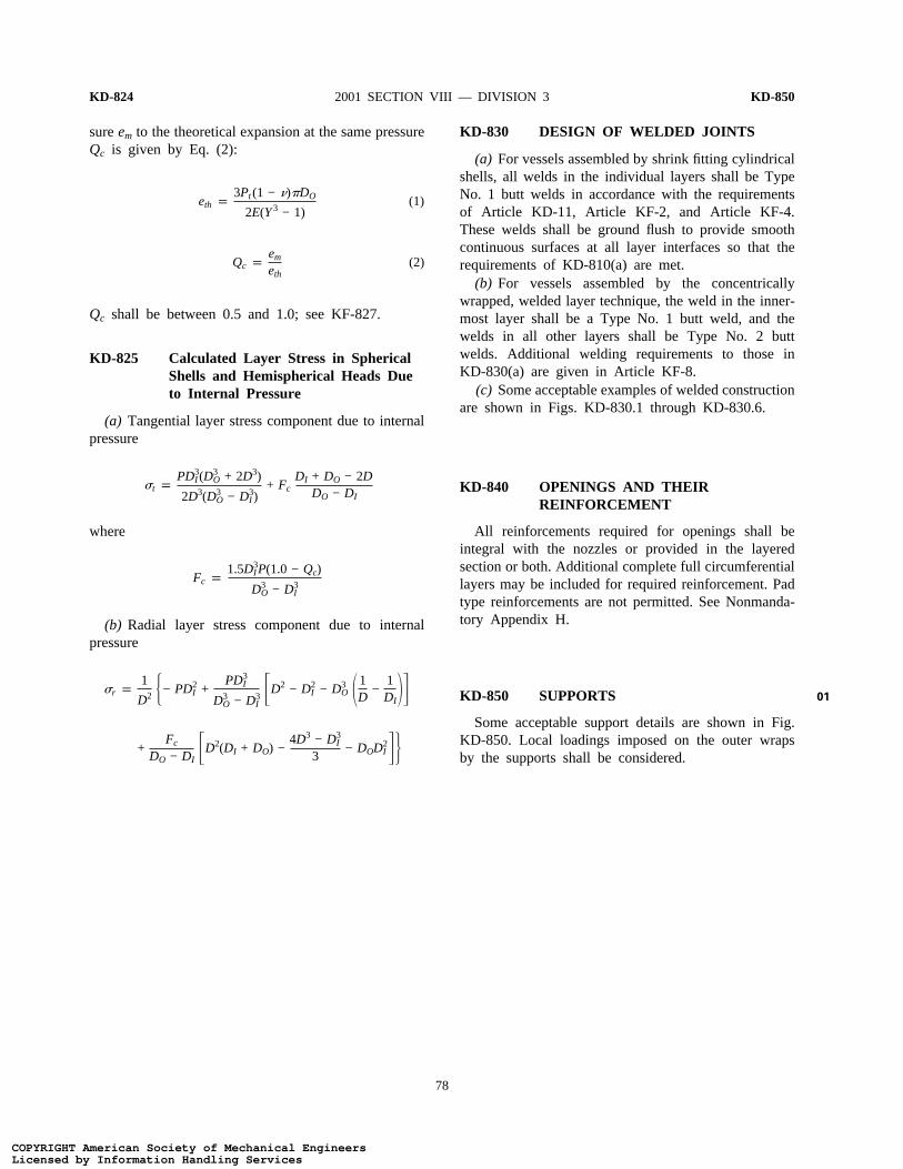
KD-830 DESIGN OF WELDED JOINTS
(a) For vessels assembled by shrink fitting cylindricalshells, all welds in the individual layers shall be TypeNo. 1 butt welds in accordance with the requirementsof Article KD-11, Article KF-2, and Article KF-4.These welds shall be ground flush to provide smoothcontinuous surfaces at all layer interfaces so that therequirements of KD-810(a) are met.
(b) For vessels assembled by the concentricallywrapped, welded layer technique, the weld in the inner-most layer shall be a Type No. 1 butt weld, and thewelds in all other layers shall be Type No. 2 buttwelds. Additional welding requirements to those inKD-830(a) are given in Article KF-8.
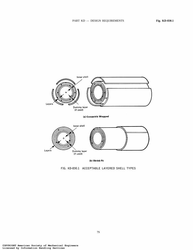
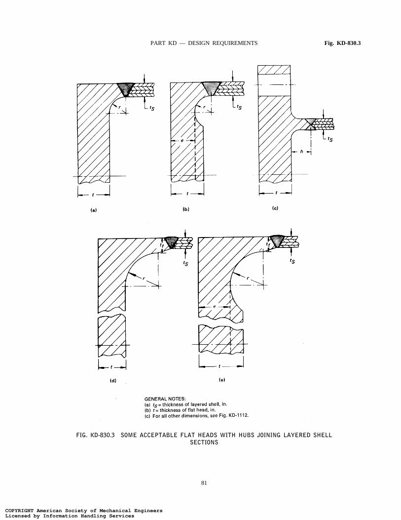
(c) Some acceptable examples of welded constructionare shown in Figs. KD-830.1 through KD-830.6.
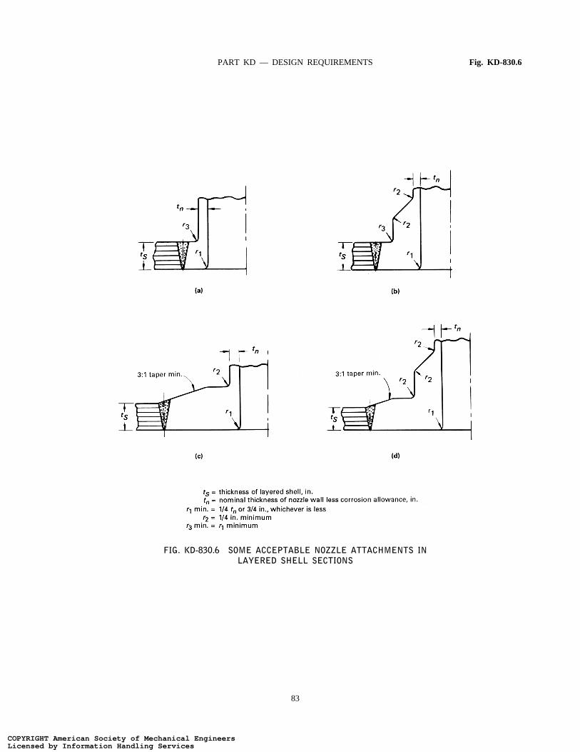
KD-840 OPENINGS AND THEIRREINFORCEMENT
All reinforcements required for openings shall beintegral with the nozzles or provided in the layeredsection or both. Additional complete full circumferentiallayers may be included for required reinforcement. Padtype reinforcements are not permitted. See Nonmanda-tory Appendix H.
KD-850 SUPPORTS
Some acceptable support details are shown in Fig.KD-850. Local loadings imposed on the outer wrapsby the supports shall be considered.
01
COPYRIGHT American Society of Mechanical EngineersLicensed by Information Handling ServicesCOPYRIGHT American Society of Mechanical EngineersLicensed by Information Handling Services
PART KD — DESIGN REQUIREMENTS Fig. KD-830.1
FIG. KD-830.1 ACCEPTABLE LAYERED SHELL TYPES
79
COPYRIGHT American Society of Mechanical EngineersLicensed by Information Handling ServicesCOPYRIGHT American Society of Mechanical EngineersLicensed by Information Handling Services
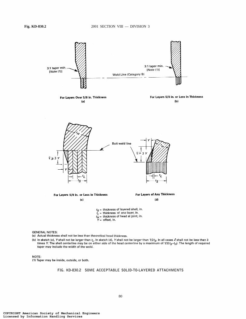
Fig. KD-830.2 2001 SECTION VIII — DIVISION 3
FIG. KD-830.2 SOME ACCEPTABLE SOLID-TO-LAYERED ATTACHMENTS
80
COPYRIGHT American Society of Mechanical EngineersLicensed by Information Handling ServicesCOPYRIGHT American Society of Mechanical EngineersLicensed by Information Handling Services
PART KD — DESIGN REQUIREMENTS Fig. KD-830.3
FIG. KD-830.3 SOME ACCEPTABLE FLAT HEADS WITH HUBS JOINING LAYERED SHELLSECTIONS
81
COPYRIGHT American Society of Mechanical EngineersLicensed by Information Handling ServicesCOPYRIGHT American Society of Mechanical EngineersLicensed by Information Handling Services
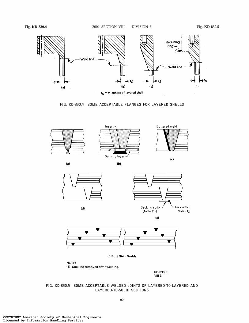
Fig. KD-830.4 2001 SECTION VIII — DIVISION 3 Fig. KD-830.5
FIG. KD-830.4 SOME ACCEPTABLE FLANGES FOR LAYERED SHELLS
FIG. KD-830.5 SOME ACCEPTABLE WELDED JOINTS OF LAYERED-TO-LAYERED ANDLAYERED-TO-SOLID SECTIONS
82
COPYRIGHT American Society of Mechanical EngineersLicensed by Information Handling ServicesCOPYRIGHT American Society of Mechanical EngineersLicensed by Information Handling Services
PART KD — DESIGN REQUIREMENTS Fig. KD-830.6
FIG. KD-830.6 SOME ACCEPTABLE NOZZLE ATTACHMENTS INLAYERED SHELL SECTIONS
83
COPYRIGHT American Society of Mechanical EngineersLicensed by Information Handling ServicesCOPYRIGHT American Society of Mechanical EngineersLicensed by Information Handling Services
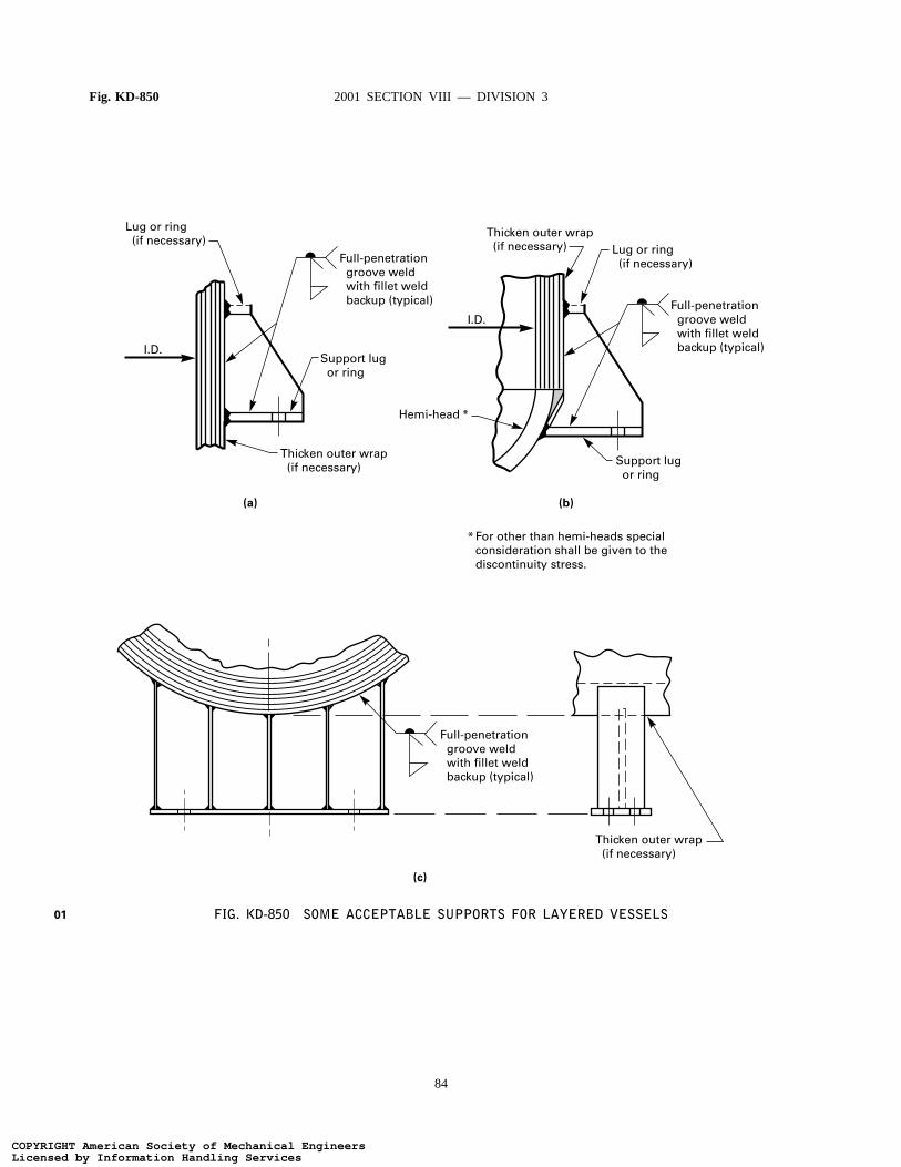
Fig. KD-850 2001 SECTION VIII — DIVISION 3
Support lug or ring
Support lug or ring
Full-penetration groove weld with fillet weld backup (typical) Full-penetration
groove weld with fillet weld backup (typical)
Full-penetration groove weld with fillet weld backup (typical)
Lug or ring (if necessary)
Lug or ring (if necessary)
Thicken outer wrap (if necessary)
Thicken outer wrap (if necessary)
Thicken outer wrap (if necessary)
(a) (b)
(c)
Hemi-head
For other than hemi-heads specialconsideration shall be given to thediscontinuity stress.
I.D.
I.D.
FIG. KD-850 SOME ACCEPTABLE SUPPORTS FOR LAYERED VESSELS01
84
COPYRIGHT American Society of Mechanical EngineersLicensed by Information Handling ServicesCOPYRIGHT American Society of Mechanical EngineersLicensed by Information Handling Services