asian vehicle emission control conference 2004 - meca · asian vehicle emission control conference...
TRANSCRIPT
Barry J. Cooper Johnson Matthey
Environmental Catalysts and Technologies
HDD Retrofit Technologies
Asian Vehicle Emission Control Conference2004
Outline
• Diesel Engine Emissions and Control Systems
• PM Control Technologies
• NOx Control Technologies
• Conclusions
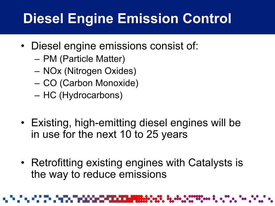
Diesel Engine Emission Control
• Diesel engine emissions consist of:– PM (Particle Matter)– NOx (Nitrogen Oxides)– CO (Carbon Monoxide)– HC (Hydrocarbons)
• Existing, high-emitting diesel engines will be in use for the next 10 to 25 years
• Retrofitting existing engines with Catalysts is the way to reduce emissions
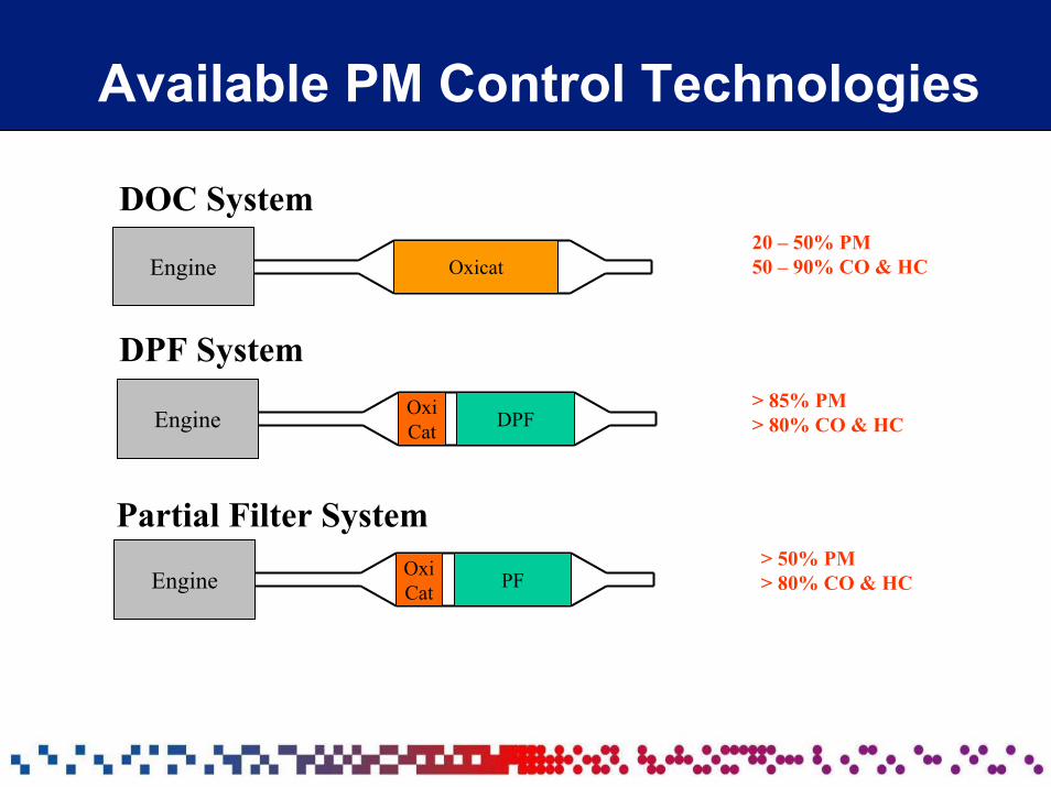
Available PM Control Technologies
DOC System
Engine Oxicat
DPF System
20 – 50% PM50 – 90% CO & HC
Engine OxiCat DPF
> 85% PM> 80% CO & HC
Partial Filter System
Engine OxiCat PF
> 50% PM> 80% CO & HC
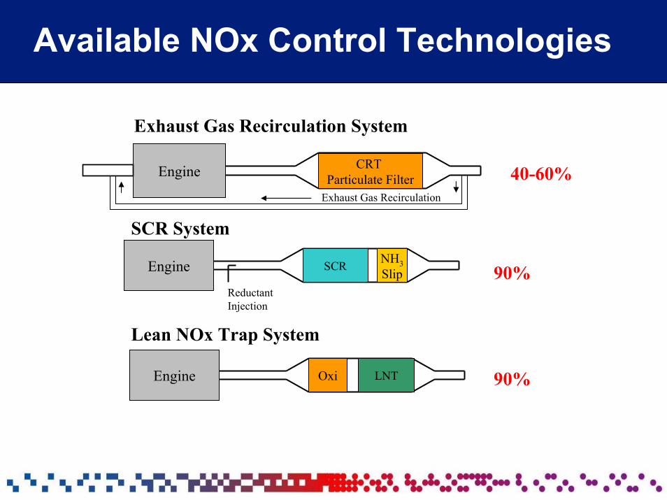
Available NOx Control Technologies
Exhaust Gas Recirculation System
Engine CRT Particulate Filter 40-60%
Exhaust Gas Recirculation
SCR System
Engine SCR NH3Slip
ReductantInjection
90%
Lean NOx Trap System
Engine LNTOxi 90%
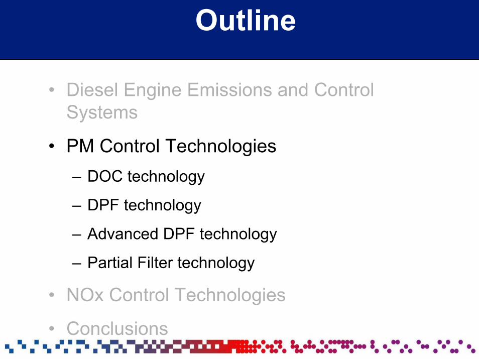
Outline
• Diesel Engine Emissions and Control Systems
• PM Control Technologies– DOC technology
– DPF technology
– Advanced DPF technology
– Partial Filter technology
• NOx Control Technologies
• Conclusions
Diesel Oxidation Catalyst
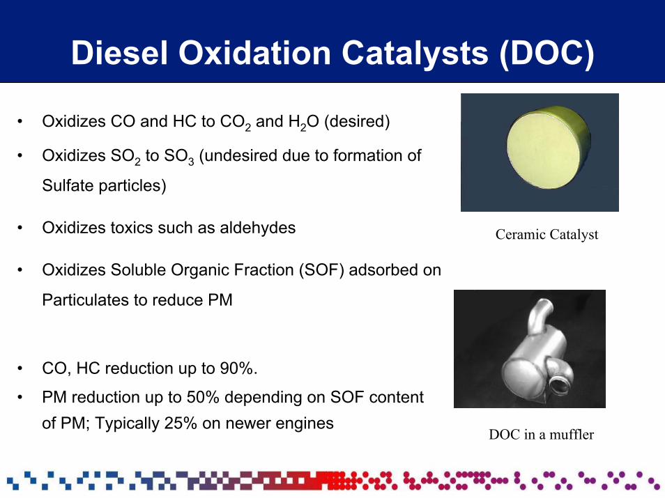
Diesel Oxidation Catalysts (DOC)
• Oxidizes CO and HC to CO2 and H2O (desired)
• Oxidizes SO2 to SO3 (undesired due to formation of
Sulfate particles)
• Oxidizes toxics such as aldehydes
• Oxidizes Soluble Organic Fraction (SOF) adsorbed on
Particulates to reduce PM
• CO, HC reduction up to 90%.
• PM reduction up to 50% depending on SOF content of PM; Typically 25% on newer engines
Ceramic Catalyst
DOC in a muffler
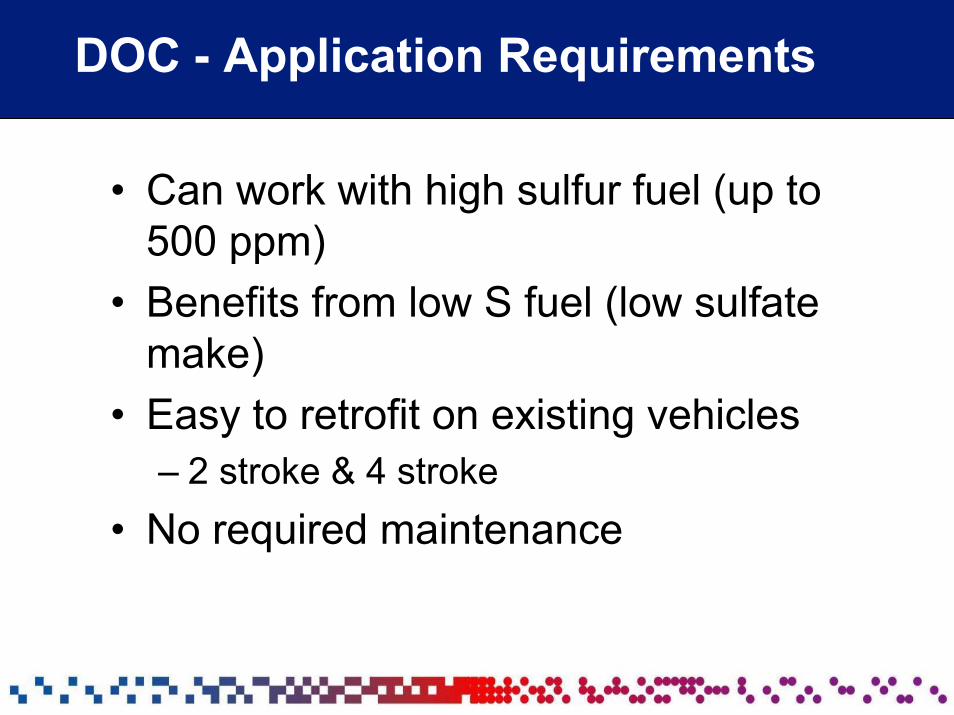
DOC - Application Requirements
• Can work with high sulfur fuel (up to 500 ppm)
• Benefits from low S fuel (low sulfate make)
• Easy to retrofit on existing vehicles– 2 stroke & 4 stroke
• No required maintenance
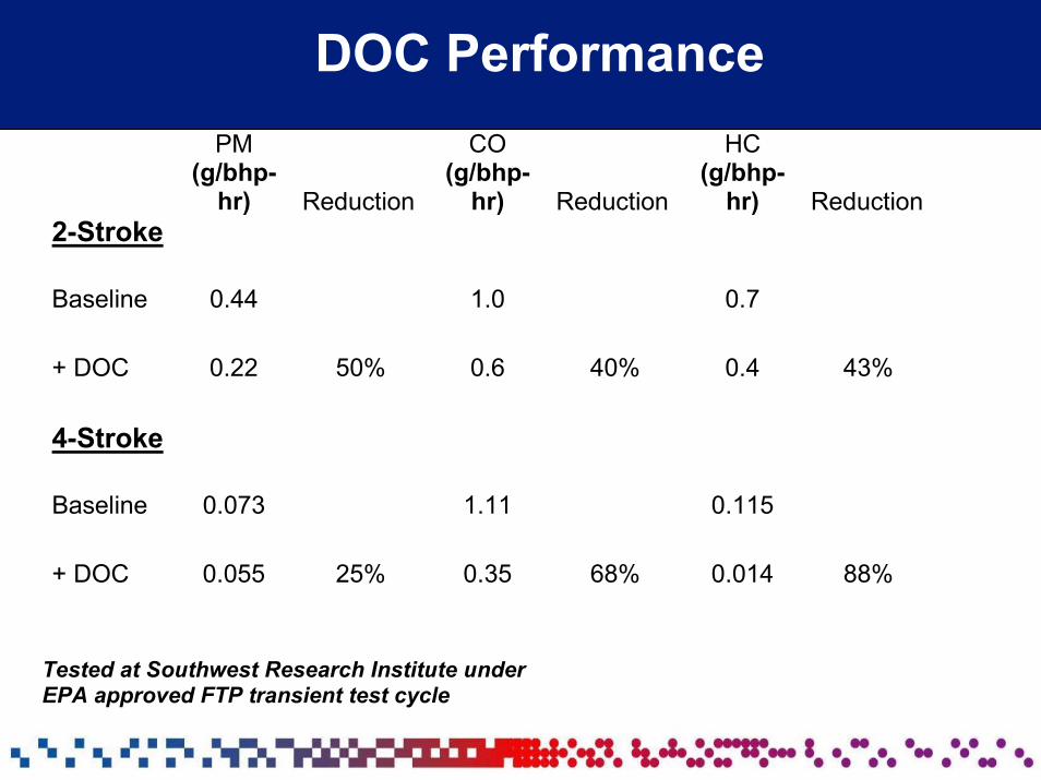
DOC Performance PM
(g/bhp-hr) Reduction
CO (g/bhp-
hr) Reduction
HC (g/bhp-
hr) Reduction2-Stroke
Baseline 0.44 1.0 0.7
+ DOC 0.22 50% 0.6 40% 0.4 43%
4-Stroke
Baseline 0.073 1.11 0.115
+ DOC 0.055 25% 0.35 68% 0.014 88%
Tested at Southwest Research Institute under EPA approved FTP transient test cycle
Diesel Particulate Filter
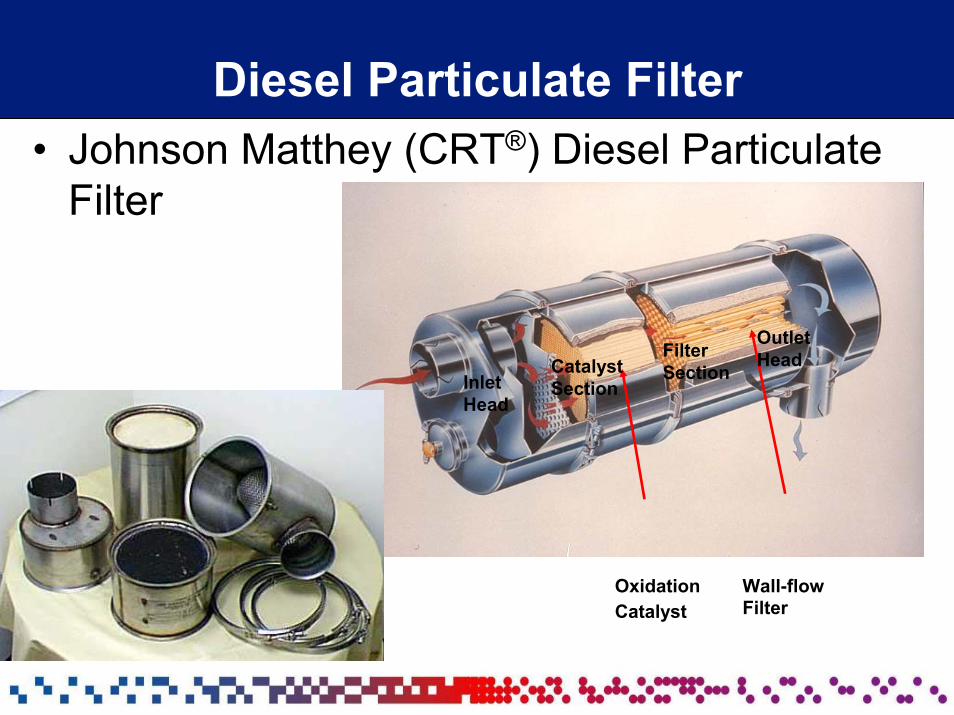
Diesel Particulate Filter• Johnson Matthey (CRT®) Diesel Particulate
Filter
InletHead
CatalystSection
Filter Section
OutletHead
OxidationCatalyst
Wall-flowFilter
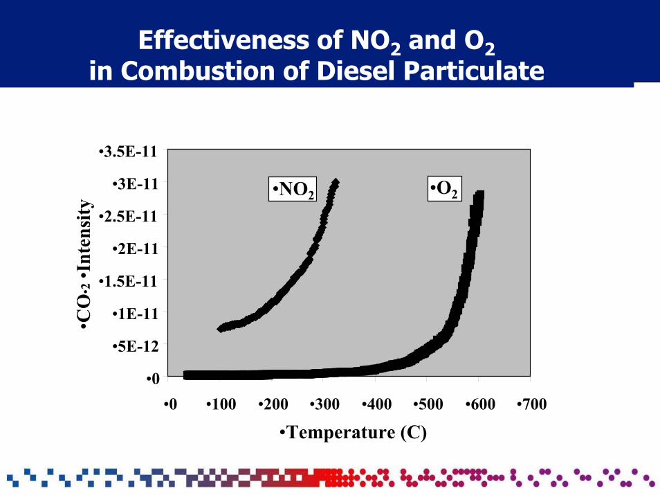
Effectiveness of NO2 and O2in Combustion of Diesel Particulate
•0
•5E-12
•1E-11
•1.5E-11
•2E-11
•2.5E-11
•3E-11
•3.5E-11
•CO
•2•I
nten
sity
•NO2 •O2
•0 •100 •200 •300 •400 •500 •600 •700
•Temperature (C)
CRT® Particulate Filter
• CRT controls CO/HC/PM
• Comprises Pre-Catalyst & Un-catalyzed Filter
• Uses NO2 produced by a pre- catalyst to burn soot in the filter at typical operating temperatures of diesel engine exhaust
• Engineered as a totally passive emission control system which requires no supplemental heat
• Requires the use of Ultra Low Sulfur fuel for maximum emission reduction and effective filter regeneration
Factors Affecting Passive CRT Application
• Exhaust temperature– 40% time at >260 C
• PM emissions– US 1991 and beyond emissions ( <0.25g/bhp.hr)
• NOx/PM ratio– >25
• Fuel sulfur level– Maximum 50 ppm
• CRT filter system needs low sulfur (< 50 ppm) diesel fuel for:– Effective filter regeneration through efficient soot combustion– Elimination of sulfate helps in very low PM emission
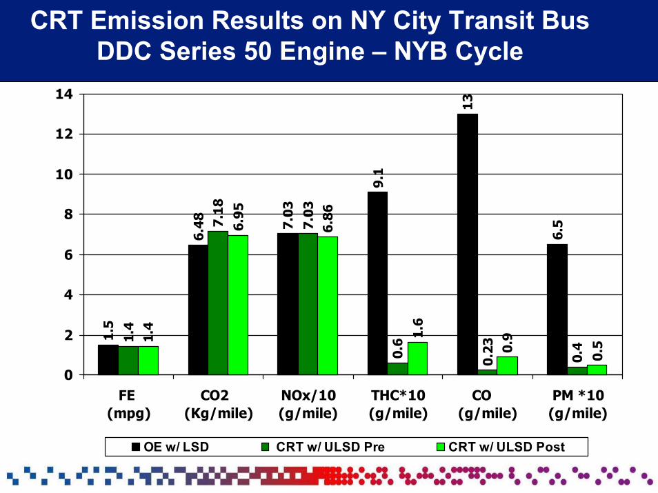
CRT Emission Results on NY City Transit BusDDC Series 50 Engine – NYB Cycle
1.5
6.48 7.
03
9.1
13
6.5
1.4
7.18
7.03
0.6
0.23
0.41.
4
6.95
6.86
1.6
0.9
0.5
0
2
4
6
8
10
12
14
FE (mpg)
CO2 (Kg/mile)
NOx/10(g/mile)
THC*10(g/mile)
CO (g/mile)
PM *10(g/mile)
OE w/ LSD CRT w/ ULSD Pre CRT w/ ULSD Post
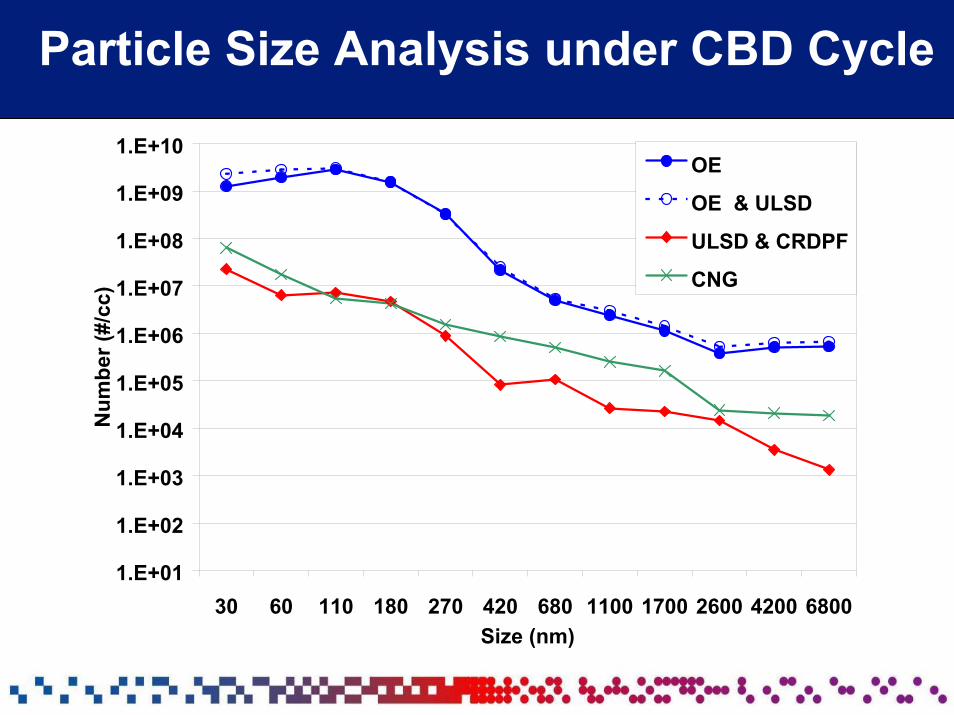
Particle Size Analysis under CBD Cycle
1.E+01
1.E+02
1.E+03
1.E+04
1.E+05
1.E+06
1.E+07
1.E+08
1.E+09
1.E+10
30 60 110 180 270 420 680 1100 1700 2600 4200 6800Size (nm)
Num
ber (
#/cc
)
OE
OE & ULSD
ULSD & CRDPF
CNG
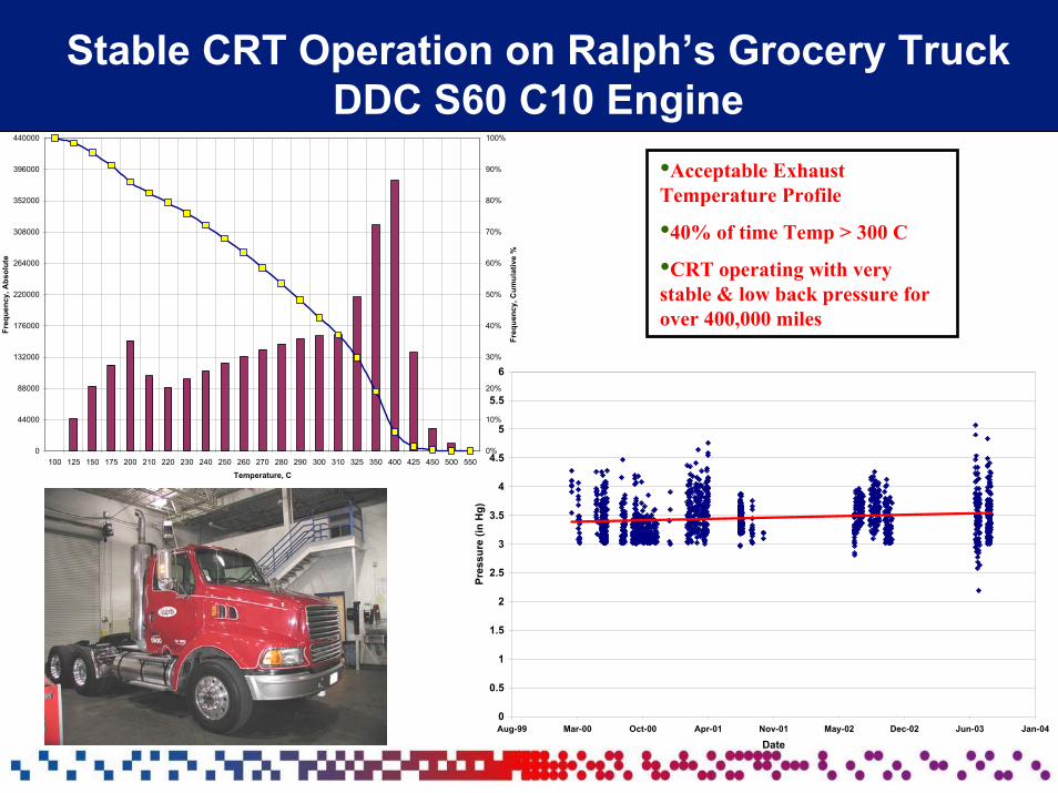
Stable CRT Operation on Ralph’s Grocery TruckDDC S60 C10 Engine
0
0.5
1
1.5
2
2.5
3
3.5
4
4.5
5
5.5
6
Aug-99 Mar-00 Oct-00 Apr-01 Nov-01 May-02 Dec-02 Jun-03 Jan-04
Date
Pres
sure
(in
Hg)
0
44000
88000
132000
176000
220000
264000
308000
352000
396000
440000
100 125 150 175 200 210 220 230 240 250 260 270 280 290 300 310 325 350 400 425 450 500 550
Temperature, C
Freq
uenc
y, A
bsol
ute
0%
10%
20%
30%
40%
50%
60%
70%
80%
90%
100%
Freq
uenc
y, C
umul
ativ
e %
•Acceptable Exhaust Temperature Profile
•40% of time Temp > 300 C
•CRT operating with very stable & low back pressure for over 400,000 miles
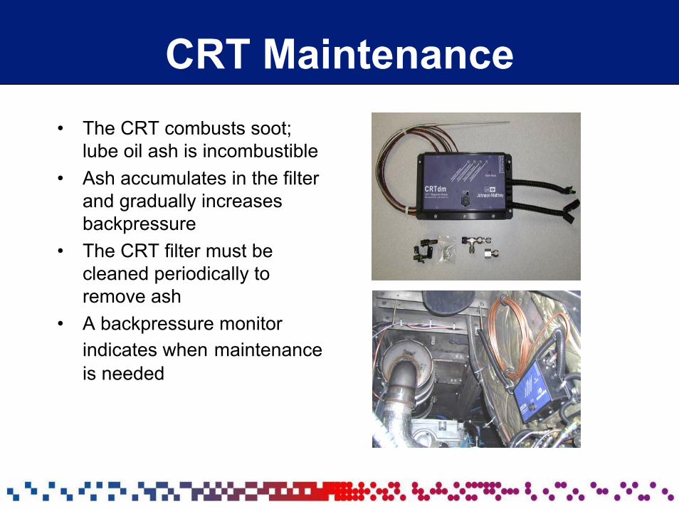
CRT Maintenance• The CRT combusts soot;
lube oil ash is incombustible• Ash accumulates in the filter
and gradually increases backpressure
• The CRT filter must be cleaned periodically to remove ash
• A backpressure monitor indicates when maintenance is needed
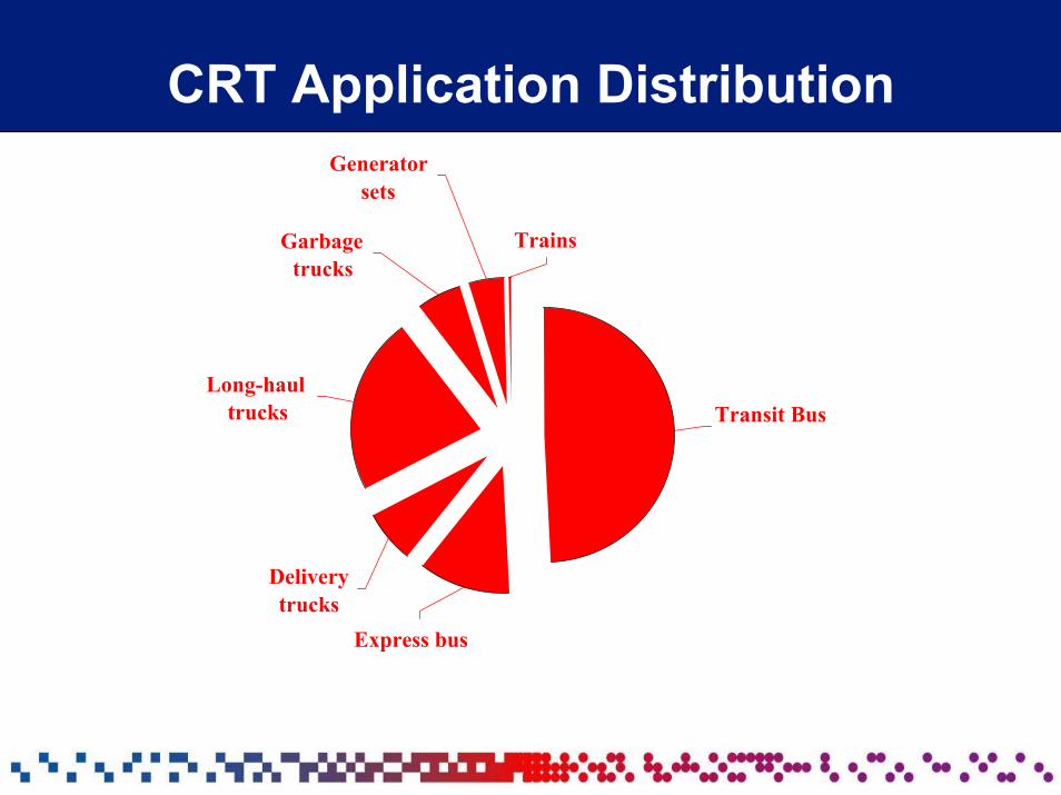
CRT Application Distribution
Garbage trucks
Long-haul trucks
Delivery trucks
Express bus
Transit Bus
Trains
Generator sets
Advanced Diesel Particulate Filter
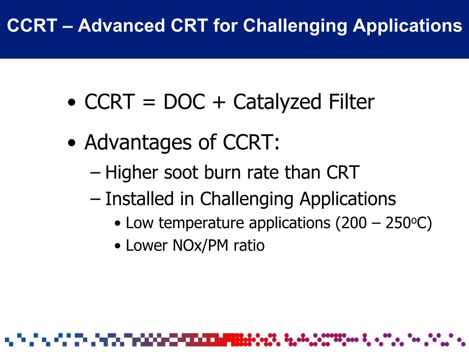
CCRT – Advanced CRT for Challenging Applications
• CCRT = DOC + Catalyzed Filter
• Advantages of CCRT:– Higher soot burn rate than CRT – Installed in Challenging Applications
• Low temperature applications (200 – 250oC) • Lower NOx/PM ratio
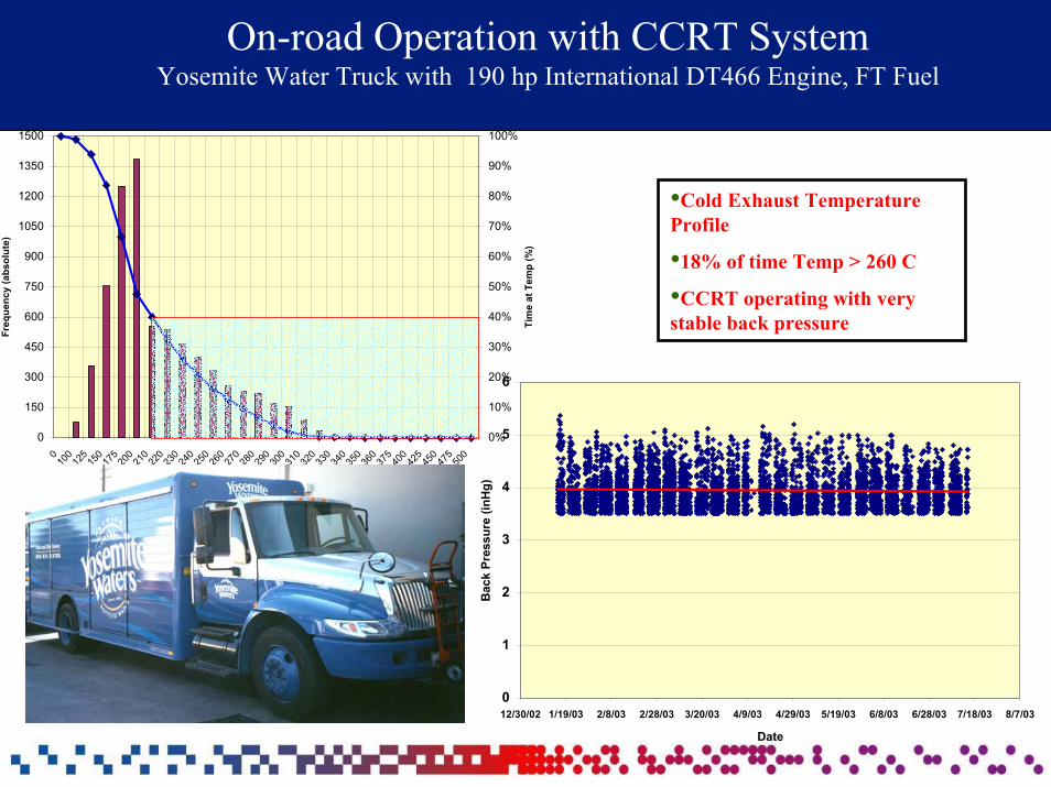
On-road Operation with CCRT SystemYosemite Water Truck with 190 hp International DT466 Engine, FT Fuel
0
150
300
450
600
750
900
1050
1200
1350
1500
010
012
515
017
520
021
022
023
024
025
026
027
028
029
030
031
032
033
034
035
036
037
540
042
545
047
550
0
Temperature (C)
Freq
uenc
y (a
bsol
ute)
0%
10%
20%
30%
40%
50%
60%
70%
80%
90%
100%
Tim
e at
Tem
p (%
)
0
1
2
3
4
5
6
12/30/02 1/19/03 2/8/03 2/28/03 3/20/03 4/9/03 4/29/03 5/19/03 6/8/03 6/28/03 7/18/03 8/7/03
Date
Bac
k Pr
essu
re (i
nHg)
•Cold Exhaust Temperature Profile
•18% of time Temp > 260 C
•CCRT operating with very stable back pressure
Partial Filter Systems
Partial Filter
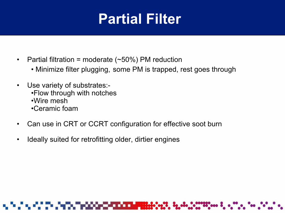
• Partial filtration = moderate (~50%) PM reduction• Minimize filter plugging, some PM is trapped, rest goes through
• Use variety of substrates:-•Flow through with notches •Wire mesh •Ceramic foam
• Can use in CRT or CCRT configuration for effective soot burn
• Ideally suited for retrofitting older, dirtier engines
Partial Filter
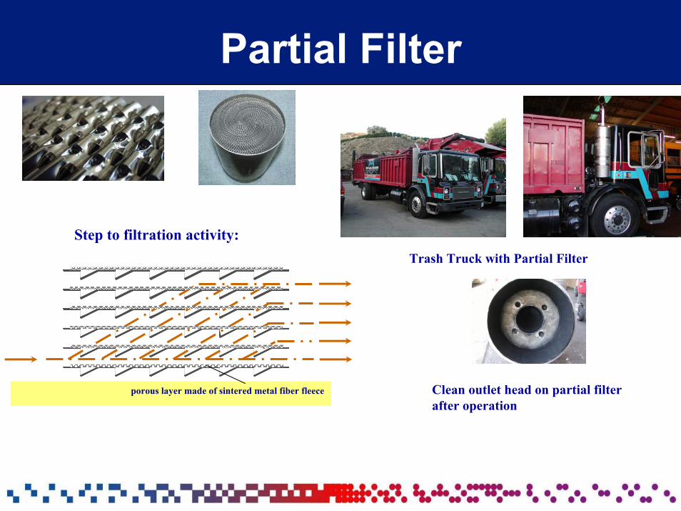
Step to filtration activity: Trash Truck with Partial Filter
porous layer made of sintered metal fiber fleece Clean outlet head on partial filter after operation
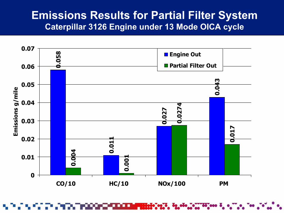
Emissions Results for Partial Filter SystemCaterpillar 3126 Engine under 13 Mode OICA cycle
0102030405060708090
1st Qtr 2nd Qtr 3rd Qtr 4th Qtr
EastWestNorth
0.0
58
0.0
11
0.0
27
0.0
43
0.0
04
0.0
01
0.0
27
4
0.0
17
0
0.01
0.02
0.03
0.04
0.05
0.06
0.07
CO/10 HC/10 NOx/100 PM
Emis
sion
s g/
mile
Engine Out
Partial Filter Out
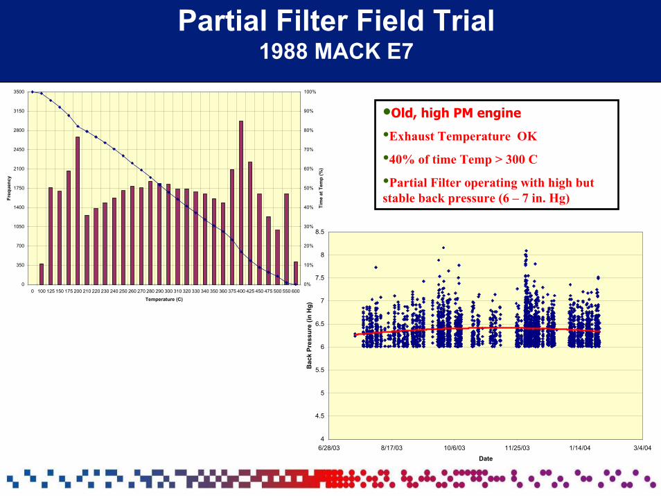
Partial Filter Field Trial1988 MACK E7
4
4.5
5
5.5
6
6.5
7
7.5
8
8.5
6/28/03 8/17/03 10/6/03 11/25/03 1/14/04 3/4/04Date
Bac
k Pr
essu
re (i
n H
g)
0
350
700
1050
1400
1750
2100
2450
2800
3150
3500
0 100 125 150 175 200 210 220 230 240 250 260 270 280 290 300 310 320 330 340 350 360 375 400 425 450 475 500 550 600
Temperature (C)
Freq
uenc
y
0%
10%
20%
30%
40%
50%
60%
70%
80%
90%
100%
Tim
e at
Tem
p (%
)
•Old, high PM engine
•Exhaust Temperature OK
•40% of time Temp > 300 C
•Partial Filter operating with high but stable back pressure (6 – 7 in. Hg)
Outline
• Diesel Engine Emissions
• PM Control Technologies– Fuel Sulfur Effect
• NOx Control Technologies– EGRT
– SCRT
• Conclusions
EGRT
EGRT™ System• EGR = Re-circulation of part of the exhaust gas to engine intake air
• EGRT uses STT patented EGR technology in combination with the CRT particulate filter
• ULSD (< 50 ppm) fuel is required
• Over 1200 units installed in Sweden and Hong Kong– Over 125,000 miles durability proven on single units in Europe
• US introduction 2001– Over 2 years of durability proven– Over 500 units in operation in the US
Principle of Operation of EGRT
• Exhaust gas is re-circulated to the engine air intake via a low pressure cooled EGR– Clean exhaust is taken after the CRT filter
• EGR system is customized for the engine– Requires development of EGR Map – Map is developed based on limiting conditions
• NOx/PM ratio• Fuel economy
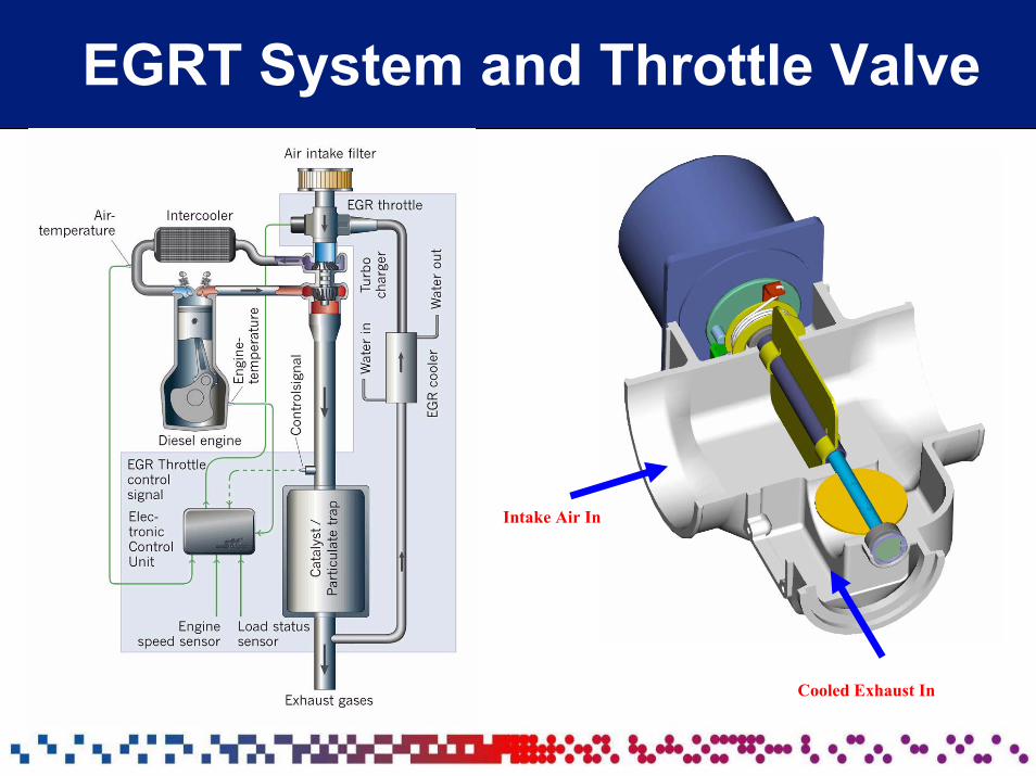
EGRT System and Throttle Valve
Intake Air In
Cooled Exhaust In
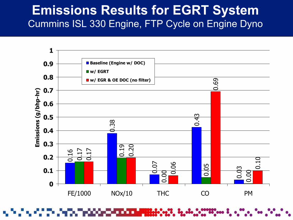
Emissions Results for EGRT SystemCummins ISL 330 Engine, FTP Cycle on Engine Dyno
0.16
0.38
0.07
0.43
0.03
0.17 0.19
0.00 0.
05
0.00
0.17 0.20
0.06
0.69
0.10
0
0.1
0.2
0.3
0.4
0.5
0.6
0.7
0.8
0.9
1
FE/1000 NOx/10 THC CO PM
Emis
sion
s (g
/bh
p-h
r)
Baseline (Engine w/ DOC)
w/ EGRT
w/ EGR & OE DOC (no filter)
Selective Catalytic Reduction
(SCR)
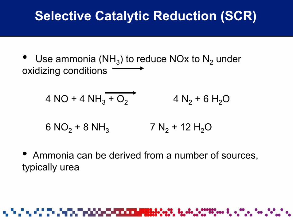
Selective Catalytic Reduction (SCR)
• Use ammonia (NH3) to reduce NOx to N2 under oxidizing conditions
4 NO + 4 NH3 + O2 4 N2 + 6 H2O
6 NO2 + 8 NH3 7 N2 + 12 H2O
• Ammonia can be derived from a number of sources, typically urea
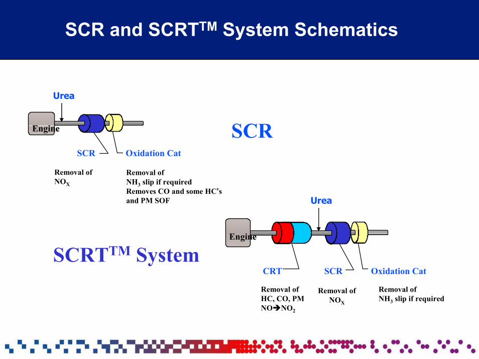
SCR and SCRTTM System Schematics
EngineEngine
SCR Oxidation Cat
Removal of NOX
Removal of NH3 slip if requiredRemoves CO and some HC’sand PM SOF
Urea
EngineEngine
CRT SCR Oxidation Cat
Removal of HC, CO, PMNO NO2
Removal of NOX
Removal of NH3 slip if required
Urea
SCR
SCRTTM System
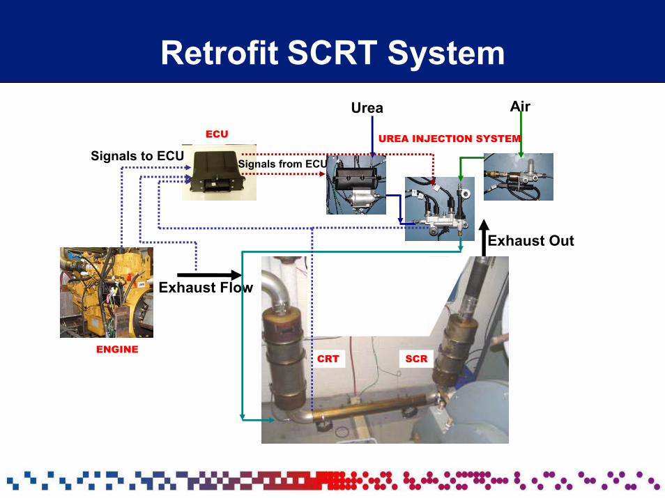
Retrofit SCRT System
Exhaust Flow
Urea Air
Urea Injection
Signals to ECU Signals from ECU
ENGINE
ECU UREA INJECTION SYSTEM
Exhaust Out
CRT SCR
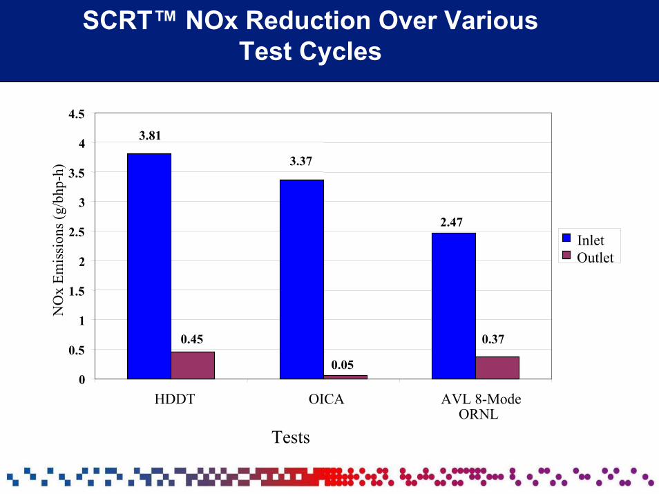
SCRT™ NOx Reduction Over Various Test Cycles
0
0.5
1
1.5
2
2.5
3
3.5
4
4.5
HDDT OICA AVL 8-ModeORNL
Tests
NO
x Em
issi
ons (
g/bh
p-h)
InletOutlet
3.81
0.45
3.37
0.05
2.47
0.37
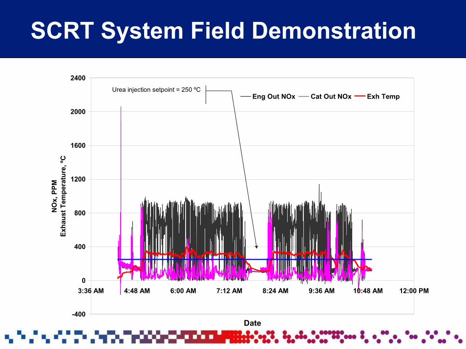
SCRT System Field Demonstration
-400
0
400
800
1200
1600
2000
2400
3:36 AM 4:48 AM 6:00 AM 7:12 AM 8:24 AM 9:36 AM 10:48 AM 12:00 PM
Date
NO
x, P
PM
Exha
ust T
empe
ratu
re, º
C
Eng Out NOx Cat Out NOx Exh TempUrea injection setpoint = 250 ºC
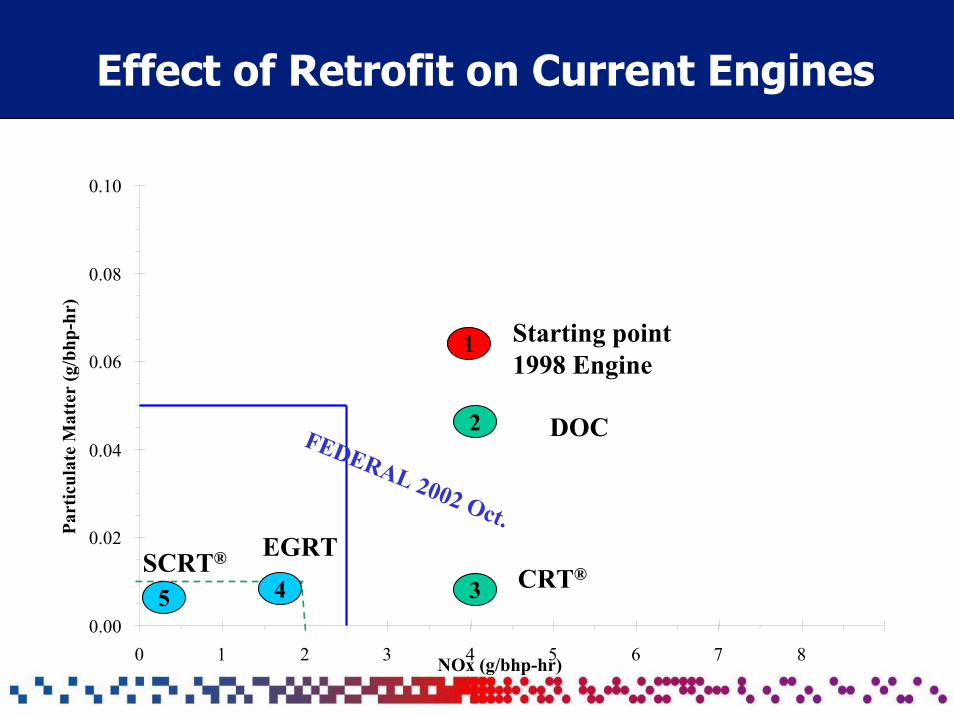
Effect of Retrofit on Current Engines
NOx (g/bhp-hr)4 5
Part
icul
ate
Mat
ter
(g/b
hp-h
r)
1
2
Starting point1998 Engine
FEDERAL 2002 Oct.
4 3 CRT®EGRT
DOC
SCRT®
5
0.10
0.08
0.06
0.04
0.02
0.000 1 2 3 6 7 8
Conclusions
• A number of emission control catalyst technologies now exists to aid the emissions engineer in achieving very low emission levels from diesel engines
• Johnson Matthey provides a variety of PM and NOx control technologies for retrofit
– PM Control: DOC, CRT, CCRT, PF– NOx Control: EGRT, SCR, and SCRT
• Improved fuel quality especially ultra low sulfur fuel (< 50 ppm) enables use of the most advanced control strategies