aruba ap-304, ap-305, ap-314, ap-315, ap-334, ap-335, ap
TRANSCRIPT
Aruba AP-3XX Wireless Access Points with ArubaOS FIPS Firmware FIPS 140-2 Level 2 Security Policy
Aruba AP-304, AP-305, AP-314,
AP-315, AP-334, AP-335, AP-365,
and AP-367 Wireless Access
Points
with ArubaOS FIPS Firmware
Non-Proprietary Security Policy
FIPS 140-2 Level 2
Version 1.5
December 2020

Aruba AP-3XX Wireless Access Points with ArubaOS FIPS Firmware FIPS 140-2 Level 2 Security Policy
Copyright
© 2020 Hewlett Packard Enterprise Company. Hewlett Packard Enterprise Company trademarks include , Aruba Networks®, Aruba Wireless Networks®, the registered Aruba the Mobile Edge Company logo, Aruba Mobility Management System®, Mobile Edge Architecture®, People Move. Networks Must Follow®, RFProtect®, Green Island®. All rights reserved. All other trademarks are the property of their respective owners.
Open Source Code
Certain Hewlett Packard Enterprise Company products include Open Source software code developed by third parties, including software code subject to the GNU General Public License (GPL), GNU Lesser General Public License (LGPL), or other Open Source Licenses. The Open Source code used can be found at this site:
http://www.arubanetworks.com/open_source
Legal Notice
The use of Aruba switching platforms and software, by all individuals or corporations, to terminate other vendors’ VPN client devices constitutes complete acceptance of liability by that individual or corporation for this action and indemnifies, in full, Aruba. from any and all legal actions that might be taken against it with respect to infringement of copyright on behalf of those vendors.
Warranty
This hardware product is protected by the standard Aruba warranty of one year parts/labor. For more information, refer to the ARUBACARE SERVICE AND SUPPORT TERMS AND CONDITIONS.
Altering this device (such as painting it) voids the warranty.
www.arubanetworks.com
3333 Scott Blvd Santa Clara, CA, USA 95054 Phone: 408.227.4500 Fax 408.227.4550

Aruba AP-3XX Wireless Access Points with ArubaOS FIPS Firmware FIPS 140-2 Level 2 Security Policy |3
Contents
1. Purpose of this Document ..................................................................................................................................................... 6
1.1. Related Documents ...................................................................................................................................................... 6
1.2. Additional Product Information .................................................................................................................................... 6
1.3. Acronyms and Abbreviations ........................................................................................................................................ 7
2. Product Overview .................................................................................................................................................................. 8
2.1 AP-300 Series ................................................................................................................................................................ 8
2.1.1 Physical Description ............................................................................................................................................. 9
2.1.2 Dimensions/Weight ............................................................................................................................................. 9
2.1.3 Environmental ...................................................................................................................................................... 9
2.1.4 Interfaces ............................................................................................................................................................. 9
2.2 AP-310 Series .............................................................................................................................................................. 11
2.2.1 Physical Description ........................................................................................................................................... 12
2.2.2 Dimensions/Weight ........................................................................................................................................... 12
2.2.3 Environmental .................................................................................................................................................... 12
2.2.4 Interfaces ........................................................................................................................................................... 12
2.3 AP-330 Series .............................................................................................................................................................. 14
2.3.1 Physical Description ........................................................................................................................................... 15
2.3.2 Dimensions/Weight ........................................................................................................................................... 15
2.3.3 Environmental .................................................................................................................................................... 15
2.3.4 Interfaces ........................................................................................................................................................... 15
2.4 AP-360 Series .............................................................................................................................................................. 17
2.4.1 Physical Description ........................................................................................................................................... 18
2.4.2 Dimensions/Weight ........................................................................................................................................... 18
2.4.3 Environmental .................................................................................................................................................... 18
2.4.4 Interfaces ........................................................................................................................................................... 18
3. Module Objectives .............................................................................................................................................................. 20
3.1. Security Levels ............................................................................................................................................................ 20
4. Physical Security .................................................................................................................................................................. 21
5. Operational Environment .................................................................................................................................................... 21
6. Logical Interfaces ................................................................................................................................................................. 21
7. Roles, Authentication and Services ..................................................................................................................................... 22
7.1 Roles ........................................................................................................................................................................... 22
7.2 Authentication ............................................................................................................................................................ 23
7.2.1 Crypto Officer Authentication ................................................................................................................................ 23
7.2.2 User Authentication ............................................................................................................................................... 23
7.2.3 Wireless Client Authentication ............................................................................................................................... 23
7.2.4 Strength of Authentication Mechanisms ............................................................................................................... 24
7.3 Services ....................................................................................................................................................................... 25
7.3.1 Crypto Officer Services ........................................................................................................................................... 25
7.3.2 User Services .......................................................................................................................................................... 26
7.3.3 Wireless Client Services .......................................................................................................................................... 26
7.3.4 Unauthenticated Services ...................................................................................................................................... 27
7.3.5 Services Available in Non-FIPS Mode ..................................................................................................................... 27
7.3.6 Non-Approved Services Non-Approved in FIPS Mode ........................................................................................... 27
8. Cryptographic Algorithms .................................................................................................................................................... 28
8.1. FIPS Approved Algorithms .......................................................................................................................................... 28
8.2. Non-FIPS Approved Algorithms Allowed in FIPS Mode .............................................................................................. 31
8.3. Non-FIPS Approved Algorithms used only in Non-FIPS 140 Mode ............................................................................. 31
9. Critical Security Parameters ................................................................................................................................................ 32

4| Aruba AP-3XX Wireless Access Points with ArubaOS FIPS Firmware FIPS 140-2 Level 2 Security Policy
10. Self-Tests ......................................................................................................................................................................... 37
11. Installing the Wireless Access Point ................................................................................................................................ 39
11.1. Pre-Installation Checklist ........................................................................................................................................ 39
11.2. Identifying Specific Installation Locations .............................................................................................................. 39
11.3. Precautions ............................................................................................................................................................. 40
11.4. Product Examination .............................................................................................................................................. 40
11.5. Package Contents ................................................................................................................................................... 40
12. Tamper-Evident Labels .................................................................................................................................................... 41
12.1. Reading TELs ........................................................................................................................................................... 41
12.2. Required TEL Locations .......................................................................................................................................... 42
12.2.1 TELs Placement on the AP-304 .......................................................................................................................... 42
12.2.2 TELs Placement on the AP-305 .......................................................................................................................... 43
12.2.3 TELs Placement on the AP-314 .......................................................................................................................... 44
12.2.4 TELs Placement on the AP-315 .......................................................................................................................... 45
12.2.5 TELs Placement on the AP-334 .......................................................................................................................... 46
12.2.6 TELs Placement on the AP-335 .......................................................................................................................... 47
12.2.7. TELs Placement on the AP-365/367 ................................................................................................................... 48
12.3. Applying TELs .......................................................................................................................................................... 49
12.4. Inspection/Testing of Physical Security Mechanisms ............................................................................................. 49
13. Secure Operation ............................................................................................................................................................ 50
13.1. Crypto Officer Management .................................................................................................................................. 51
13.2. User Guidance ........................................................................................................................................................ 51
13.3. Setup and Configuration ........................................................................................................................................ 51
13.4. Setting Up Your Wireless Access Point ................................................................................................................... 52
13.5. Enabling FIPS Mode on the Staging Controller ....................................................................................................... 52
13.5.1. Enabling FIPS Mode on the Staging Controller with the CLI .............................................................................. 52
13.6. Disallowed FIPS Mode Configurations.................................................................................................................... 53
13.7. Full Documentation ................................................................................................................................................ 53
Figures
Figure 1 - Aruba AP-304 ................................................................................................................................................................. 8
Figure 2 - Aruba AP-305 ................................................................................................................................................................. 8
Figure 3 - Aruba AP-300 Series Access Point – Interfaces ............................................................................................................ 10
Figure 4 - Aruba AP-314 ............................................................................................................................................................... 11
Figure 5 - Aruba AP-315 ............................................................................................................................................................... 11
Figure 6 - Aruba AP-310 Series Access Point – Interfaces ............................................................................................................ 13
Figure 7 - Aruba AP-334 ............................................................................................................................................................... 14
Figure 8 - Aruba AP-335 ............................................................................................................................................................... 14
Figure 9 - Aruba AP-330 Series Access Point – Interfaces ............................................................................................................ 16
Figure 10 - Aruba AP-365 ............................................................................................................................................................. 17
Figure 11 - Aruba AP-367 ............................................................................................................................................................. 17
Figure 12 - Aruba AP-360 Series Outdoor Access Point – Interfaces (with weatherproof caps).................................................. 18
Figure 13 - Tamper-Evident Labels ............................................................................................................................................... 41
Figure 14 – Top View of AP-304 with TELs ................................................................................................................................... 42
Figure 15 – Bottom View of AP-304 with TELs ............................................................................................................................. 42
Figure 16 – Top View of AP-305 with TELs ................................................................................................................................... 43
Figure 17 – Bottom View of AP-305 with TELs ............................................................................................................................. 43
Aruba AP-3XX Wireless Access Points with ArubaOS FIPS Firmware FIPS 140-2 Level 2 Security Policy |5
Figure 18 – Top View of AP-314 with TELs ................................................................................................................................... 44
Figure 19 – Bottom View of AP-314 with TELs ............................................................................................................................. 44
Figure 20 – Top View of AP-315 with TELs ................................................................................................................................... 45
Figure 21 – Bottom View of AP-315 with TELs ............................................................................................................................. 45
Figure 22 – Top View of AP-334 with TELs ................................................................................................................................... 46
Figure 23 – Bottom View of AP-334 with TELs ............................................................................................................................. 46
Figure 24 – Top View of AP-335 with TELs ................................................................................................................................... 47
Figure 25 – Bottom View of AP-335 with TELs ............................................................................................................................. 47
Figure 26 – Top View of AP-365/AP-367 with TELs ...................................................................................................................... 48
Figure 27 – Bottom View of AP-365/AP-367 with TELs ................................................................................................................ 48
Tables
Table 1 - AP-300 Series Status Indicator LEDs .............................................................................................................................. 10
Table 2 - AP-310 Series Status Indicator LEDs .............................................................................................................................. 13
Table 3 - AP-330 Series Status Indicator LEDs .............................................................................................................................. 16
Table 4 - AP-360 Series Status Indicator LEDs .............................................................................................................................. 19
Table 5 - Intended Level of Security ............................................................................................................................................. 20
Table 6 - FIPS 140-2 Logical Interfaces ......................................................................................................................................... 21
Table 7 - Strength of Authentication Mechanisms....................................................................................................................... 24
Table 8 – Crypto Officer Services ................................................................................................................................................. 25
Table 9 - Wireless Client Services ................................................................................................................................................. 27
Table 10 - ArubaOS OpenSSL Module CAVP Certificates ............................................................................................................. 28
Table 11 - ArubaOS Crypto Module CAVP Certificates ................................................................................................................. 29
Table 12 - ArubaOS UBOOT Bootloader CAVP Certificates .......................................................................................................... 30
Table 13 – Aruba AP Hardware CAVP Certificates ....................................................................................................................... 31
Table 14 - CSPs/Keys Used in the Module .................................................................................................................................... 32
Table 15 - Inspection/Testing of Physical Security Mechanisms .................................................................................................. 49
Table 16 - FIPS Approved Modes of Operation ............................................................................................................................ 50
6| Aruba AP-3XX Wireless Access Points with ArubaOS FIPS Firmware FIPS 140-2 Level 2 Security Policy
Preface
This document may be freely reproduced and distributed whole and intact including the copyright notice.
Products identified herein contain confidential commercial firmware. Valid license required.
1. Purpose of this Document
This release supplement provides information regarding the Aruba AP-304, AP-305, AP-314, AP-315, AP-334, AP-335,
AP-365, and AP-367 Wireless Access Points with ArubaOS FIPS Firmware FIPS 140-2 Level 2 validation from Aruba
Networks. The material in this supplement modifies the general Aruba hardware and firmware documentation included
with this product and should be kept with your Aruba product documentation.
This supplement primarily covers the non-proprietary Cryptographic Module Security Policy for the Aruba AP-304, AP-
305, AP-314, AP-315, AP-334, AP-335, AP-365, and AP-367 Wireless Access Points with ArubaOS FIPS Firmware.
This security policy describes how the Access Point (AP) meets the security requirements of FIPS 140-2 Level 2 and
how to place and maintain the AP in the secure FIPS 140-2 mode. This policy was prepared as part of the FIPS 140-2
Level 2 validation of the product.
FIPS 140-2 (Federal Information Processing Standards Publication 140-2, Security Requirements for Cryptographic
Modules) details the U.S. Government requirements for cryptographic modules. More information about the FIPS 140-2
standard and validation program is available on the National Institute of Standards and Technology (NIST) website at:
https://csrc.nist.gov/projects/cryptographic-module-validation-program
In addition, in this document, the Aruba AP-304, AP-305, AP-314, AP-315, AP-334, AP-335, AP-365, and AP-367
Wireless Access Points with ArubaOS FIPS Firmware are referred to as the Wireless Access Point, the AP, the module,
the cryptographic module, Aruba Wireless Access Points, Aruba Wireless APs, Aruba Access Points, Aruba Outdoor
APs and AP-3XX Wireless APs.
1.1. Related Documents
The following items are part of the complete installation and operations documentation included with this product:
• Aruba AP-300 Series Access Points Installation Guide
• Aruba AP-310 Series Access Points Installation Guide
• Aruba AP-330 Series Access Points Installation Guide
• Aruba AP-360 Series Outdoor Access Points Installation Guide
• ArubaOS 8.X.0.0 User Guide, where X = 6, 5, or 2
• ArubaOS 8.X.0.x CLI Reference Guide, where X = 6, 5, or 2
• ArubaOS 8.X.0.0 Getting Started Guide, where X = 6, 5, or 2
• ArubaOS 8.X.0.0 Migration Guide, where X = 6, 5, or 2
• Aruba AP Software Quick Start Guide
1.2. Additional Product Information
More information is available from the following sources:
The Aruba Networks Web-site contains information on the full line of products from Aruba Networks:
http://www.arubanetworks.com
The NIST Validated Modules Web-site contains contact information for answers to technical or sales-
related questions for the product:
https://csrc.nist.gov/Projects/cryptographic-module-validation-program/Validated-Modules/Search
Enter Aruba in the Vendor field then select Search to see a list of FIPS certified Aruba products.
Select the Certificate Number for the Module Name ‘Aruba AP-304, AP-305, AP-314, AP-315,
AP-334, AP-335, AP-365, and AP-367 Wireless Access Points with ArubaOS FIPS Firmware’.
Aruba AP-3XX Wireless Access Points with ArubaOS FIPS Firmware FIPS 140-2 Level 2 Security Policy |7
1.3. Acronyms and Abbreviations
AES Advanced Encryption Standard
AP Access Point
CBC Cipher Block Chaining
CLI Command Line Interface
CO Crypto Officer
CPSec Control Plane Security protected
CSEC Communications Security Establishment Canada
CSP Critical Security Parameter
ECO External Crypto Officer
EMC Electromagnetic Compatibility
EMI Electromagnetic Interference
FE Fast Ethernet
GE Gigabit Ethernet
GHz Gigahertz
HMAC Hashed Message Authentication Code
Hz Hertz
IKE Internet Key Exchange
IPsec Internet Protocol security
KAT Known Answer Test
KEK Key Encryption Key
L2TP Layer-2 Tunneling Protocol
LAN Local Area Network
LED Light Emitting Diode
SHA Secure Hash Algorithm
SNMP Simple Network Management Protocol
SPOE Serial & Power Over Ethernet
TEL Tamper-Evident Label
TFTP Trivial File Transfer Protocol
WLAN Wireless Local Area Network

8| Aruba AP-3XX Wireless Access Points with ArubaOS FIPS Firmware FIPS 140-2 Level 2 Security Policy
2. Product Overview
This section introduces the Aruba AP-304, AP-305, AP-314, AP-315, AP-334, AP-335, AP-365, and AP-367 Wireless
Access Points, providing a brief overview and summary of the physical features of each model covered by this FIPS
140-2 security policy.
The tested versions of the firmware are: ArubaOS 8.6.0.7-FIPS, ArubaOS 8.5.0.3-FIPS and ArubaOS 8.2.2.5-FIPS.
Aruba's development processes are such that future releases under ArubaOS 8.2, 8.5 and 8.6 should be FIPS
validate-able and meet the claims made in this document. Only the versions that explicitly appear on the certificate,
however, are formally validated. The CMVP makes no claim as to the correct operation of the module or the security
strengths of the generated keys when operating under a version that is not listed on the validation certificate.
Note: For radio regulatory reasons, part numbers ending with -USF1 are to be sold in the US only. Part numbers
ending with -RWF1 are considered ‘rest of the world’ and must not be used for deployment in the United
States. From a FIPS perspective, both -USF1 and -RWF1 models are identical and fully FIPS compliant.
2.1 AP-300 Series This section introduces the Aruba AP-300 Series Wireless Access Points (APs) with FIPS 140-2 Level 2 validation. It
describes the purpose of the AP-304 and AP-305 APs, their physical attributes, and their interfaces.
Figure 1 - Aruba AP-304
Figure 2 - Aruba AP-305

Aruba AP-3XX Wireless Access Points with ArubaOS FIPS Firmware FIPS 140-2 Level 2 Security Policy |9
These compact and cost-effective dual-radio APs implement a dual radio 802.11ac Access Point with Multi-User
MIMO - Supports up to 1,300 Mbps in the 5GHz band (with 3SS/VHT80 clients) and up to 300 Mbps in the 2.4GHz
band (with 2SS/VHT40 clients).
When managed by Aruba Mobility Controllers, AP-304 and AP-305 offer centralized configuration, data
encryption, policy enforcement and network services, as well as distributed and centralized traffic forwarding.
2.1.1 Physical Description The Aruba AP-304 and AP-305 Access Points are multi-chip standalone cryptographic modules consisting of
hardware and software, all contained in a hard, opaque plastic case. Each module contains 802.11 a/b/g/n/ac
transceivers and support three external antennas through three N-type female connectors for external antennas
for the AP-304, or three internal antennas for the AP-305.
The case physically encloses the complete set of hardware and software components and represents the
cryptographic boundary of the module.
The AP-300 Series Access Points configuration validated during the cryptographic modules testing included:
AP-304 HW: AP-304-USF1 (HPE SKU JX937A)
AP-305 HW: AP-305-USF1 (HPE SKU JX938A)
2.1.2 Dimensions/Weight The AP-300 Series have the following physical dimensions (unit, excluding mount accessories):
Dimensions: 165 mm (W) x 165 mm (D) x 38 mm (H)
Weight: 460 g
2.1.3 Environmental Operating:
o Temperature: 0° C to +50° C (+32° F to +122° F) o Humidity: 5% to 93% non-condensing
Storage and transportation: o Temperature: -40° C to +70° C (-40° F to +158° F) o Humidity: 5% to 93% non-condensing
2.1.4 Interfaces The module provides the following network interface:
ENET: One Ethernet network interface (RJ-45, Auto-sensing link speed 10/100/1000BASE-T and MDI/MDX) o 802.3az Energy Efficient Ethernet (EEE) o PoE-PD: 48 VDC (nominal) 802.3af/at POE
USB 2.0 host interface (Type A connector)
Bluetooth Low Energy (BLE) radio:
Bluetooth: up to 3dBm transmit power (class 2) and -92dBm receive sensitivity

10| Aruba AP-3XX Wireless Access Points with ArubaOS FIPS Firmware FIPS 140-2 Level 2 Security Policy
Figure 3 - Aruba AP-300 Series Access Point – Interfaces
DC power interface:
12V DC (nominal, +/- 5%)
2.1mm/5.5-mm center-positive circular plug with 9.5-mm length
Antenna interfaces:
802.11a/b/g/n/ac three external antenna (AP-304) or three internal antenna (AP-305)
Other Interfaces:
Visual indicators (two multi-color LEDs): for System and Radio status
Reset button: factory reset (during device power up)
Serial console interface (proprietary; optional adapter cable available; disabled in FIPS mode by TEL)
Table 1 - AP-300 Series Status Indicator LEDs
LED Type Color/State Meaning
System Status (Left)
Off AP powered off
Green/Amber
Alternating Device booting; not ready
Green - Solid Device ready
Amber - Solid
Device ready; power-save mode (802.3af PoE):
* Single radio
* USB disabled
Green or Amber
Flashing
Device ready, restricted mode:
* Uplink negotiated in sub optimal speed; or
* Radio in non-high throughput (HT) mode
Red System error condition
Radio Status (Right)
Off AP powered off, or both radios disabled
Green - Solid Both radios enabled in access mode
Amber - Solid Both radios enabled in monitor mode
Green/Amber Blinking One radio enabled in access (Green) or monitor (Amber) mode,
other radio is disabled
Green/Amber Alternating One radio enabled in access mode, other in monitor mode
Aruba AP-3XX Wireless Access Points with ArubaOS FIPS Firmware FIPS 140-2 Level 2 Security Policy |11
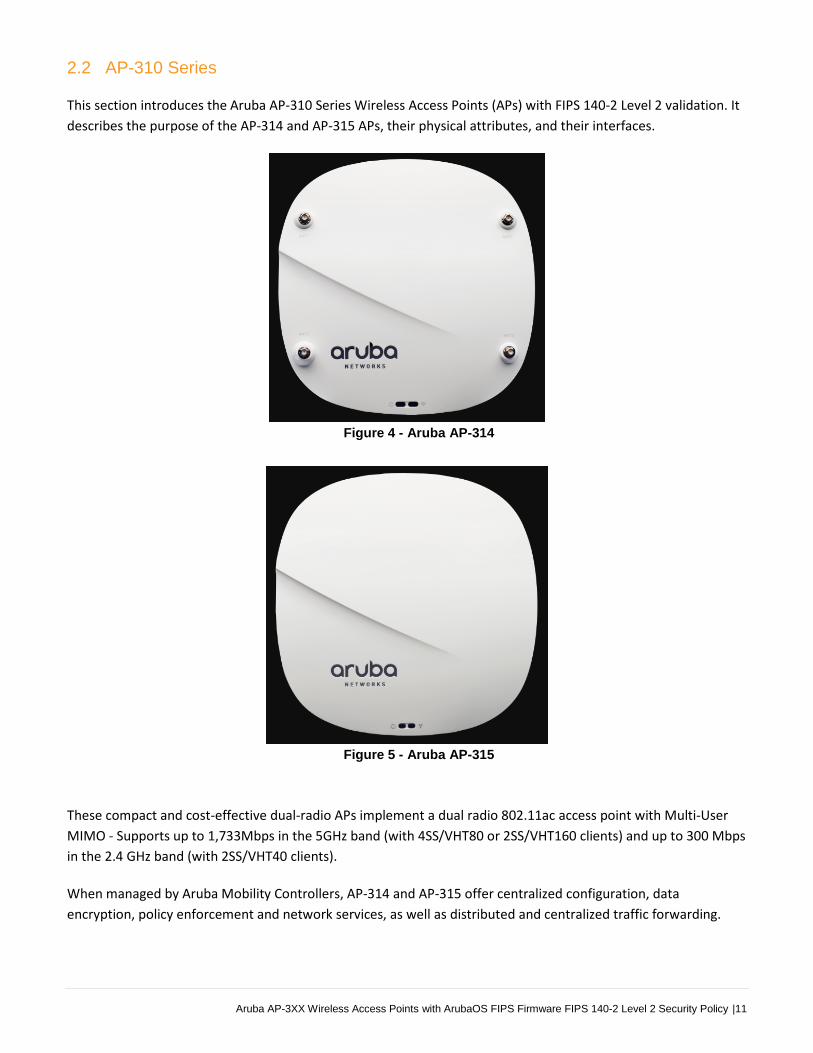
2.2 AP-310 Series
This section introduces the Aruba AP-310 Series Wireless Access Points (APs) with FIPS 140-2 Level 2 validation. It
describes the purpose of the AP-314 and AP-315 APs, their physical attributes, and their interfaces.
Figure 4 - Aruba AP-314
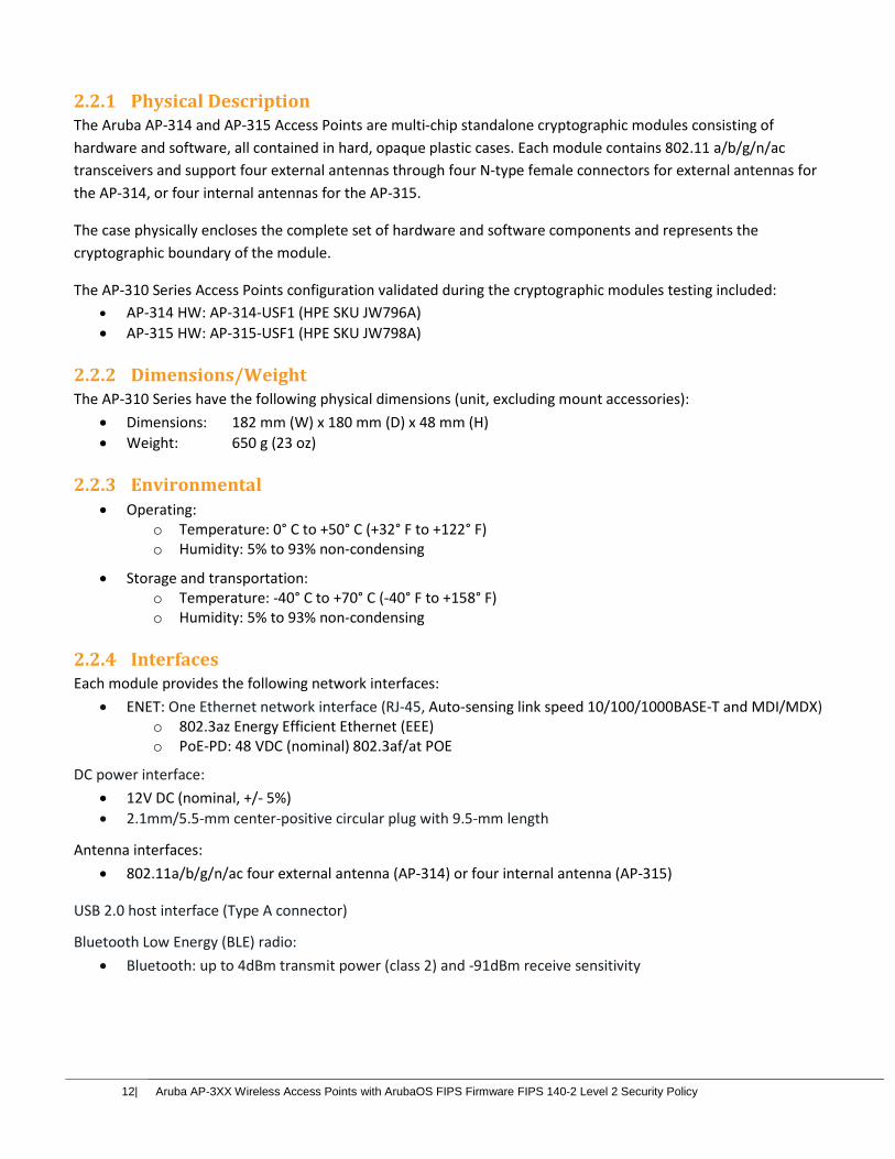
Figure 5 - Aruba AP-315
These compact and cost-effective dual-radio APs implement a dual radio 802.11ac access point with Multi-User
MIMO - Supports up to 1,733Mbps in the 5GHz band (with 4SS/VHT80 or 2SS/VHT160 clients) and up to 300 Mbps
in the 2.4 GHz band (with 2SS/VHT40 clients).
When managed by Aruba Mobility Controllers, AP-314 and AP-315 offer centralized configuration, data
encryption, policy enforcement and network services, as well as distributed and centralized traffic forwarding.
12| Aruba AP-3XX Wireless Access Points with ArubaOS FIPS Firmware FIPS 140-2 Level 2 Security Policy
2.2.1 Physical Description The Aruba AP-314 and AP-315 Access Points are multi-chip standalone cryptographic modules consisting of
hardware and software, all contained in hard, opaque plastic cases. Each module contains 802.11 a/b/g/n/ac
transceivers and support four external antennas through four N-type female connectors for external antennas for
the AP-314, or four internal antennas for the AP-315.
The case physically encloses the complete set of hardware and software components and represents the
cryptographic boundary of the module.
The AP-310 Series Access Points configuration validated during the cryptographic modules testing included:
AP-314 HW: AP-314-USF1 (HPE SKU JW796A)
AP-315 HW: AP-315-USF1 (HPE SKU JW798A)
2.2.2 Dimensions/Weight The AP-310 Series have the following physical dimensions (unit, excluding mount accessories):
Dimensions: 182 mm (W) x 180 mm (D) x 48 mm (H)
Weight: 650 g (23 oz)
2.2.3 Environmental Operating:
o Temperature: 0° C to +50° C (+32° F to +122° F) o Humidity: 5% to 93% non-condensing
Storage and transportation: o Temperature: -40° C to +70° C (-40° F to +158° F) o Humidity: 5% to 93% non-condensing
2.2.4 Interfaces Each module provides the following network interfaces:
ENET: One Ethernet network interface (RJ-45, Auto-sensing link speed 10/100/1000BASE-T and MDI/MDX) o 802.3az Energy Efficient Ethernet (EEE) o PoE-PD: 48 VDC (nominal) 802.3af/at POE
DC power interface:
12V DC (nominal, +/- 5%)
2.1mm/5.5-mm center-positive circular plug with 9.5-mm length
Antenna interfaces:
802.11a/b/g/n/ac four external antenna (AP-314) or four internal antenna (AP-315)
USB 2.0 host interface (Type A connector)
Bluetooth Low Energy (BLE) radio:
Bluetooth: up to 4dBm transmit power (class 2) and -91dBm receive sensitivity
Aruba AP-3XX Wireless Access Points with ArubaOS FIPS Firmware FIPS 140-2 Level 2 Security Policy |13
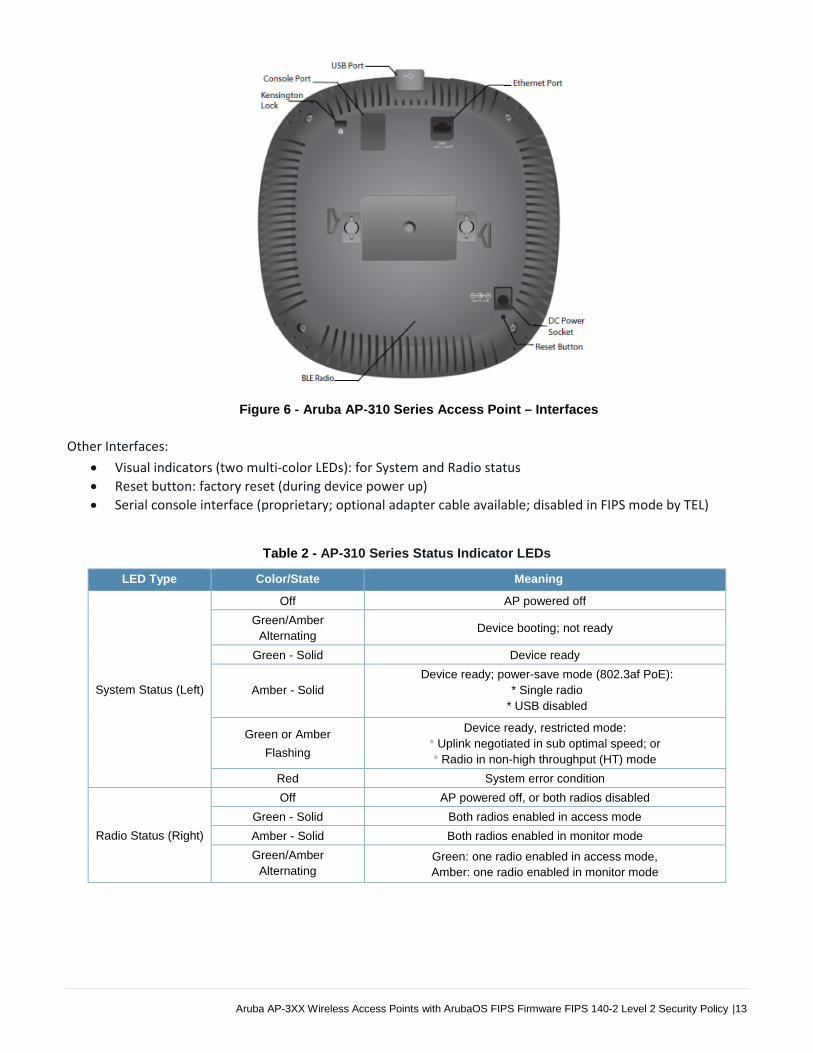
Figure 6 - Aruba AP-310 Series Access Point – Interfaces
Other Interfaces:
Visual indicators (two multi-color LEDs): for System and Radio status
Reset button: factory reset (during device power up)
Serial console interface (proprietary; optional adapter cable available; disabled in FIPS mode by TEL)
Table 2 - AP-310 Series Status Indicator LEDs
LED Type Color/State Meaning
System Status (Left)
Off AP powered off
Green/Amber
Alternating Device booting; not ready
Green - Solid Device ready
Amber - Solid
Device ready; power-save mode (802.3af PoE):
* Single radio
* USB disabled
Green or Amber
Flashing
Device ready, restricted mode:
* Uplink negotiated in sub optimal speed; or
* Radio in non-high throughput (HT) mode
Red System error condition
Radio Status (Right)
Off AP powered off, or both radios disabled
Green - Solid Both radios enabled in access mode
Amber - Solid Both radios enabled in monitor mode
Green/Amber
Alternating Green: one radio enabled in access mode,
Amber: one radio enabled in monitor mode

14| Aruba AP-3XX Wireless Access Points with ArubaOS FIPS Firmware FIPS 140-2 Level 2 Security Policy
2.3 AP-330 Series
This section introduces the Aruba AP-330 Series Wireless Access Points (APs) with FIPS 140-2 Level 2 validation. It
describes the purpose of the AP-334 and AP-335 APs, their physical attributes, and their interfaces.
Figure 7 - Aruba AP-334
Figure 8 - Aruba AP-335
With a maximum concurrent data rate of 1,733 Mbps in the 5 GHz band and 600 Mbps in the 2.4 GHz band (for an
aggregate peak data rate of 2.3Gbps), the 330 Series Access Points deliver a best-in-class, next-generation
802.11ac Wi-Fi infrastructure that is ideal for lecture halls, auditoriums, public venues, and high-density office
environments. The high performance and high density 802.11ac 330 Series Access Points support 160 MHz
channel bandwidth (VHT160), 4-stream multi-user MIMO (MU-MIMO) and 4 spatial streams (4SS).
For the AP-334, four RP-SMA connectors for external dual band antennas, with internal loss between radio
interface and external antenna connectors (due to diplexing circuitry): 2.3 dB in 2.4 GHz and 1.2 dB in 5 GHz. For
the AP-335, four (vertically polarized) integrated 2.4 GHz downtilt omni-directional antennas for 4x4 MIMO with
peak antenna gain of 3.8 dBi per antenna. Each 5 GHz radio chain has both a vertically and a horizontally polarized

Aruba AP-3XX Wireless Access Points with ArubaOS FIPS Firmware FIPS 140-2 Level 2 Security Policy |15
antenna element; AP software automatically and dynamically selects the best set of elements for each data
packet transmitted or received. Four integrated vertically polarized 5 GHz downtilt omni-directional antennas for
4x4 MIMO with peak antenna gain of 4.9 dBi per antenna, plus four integrated horizontally polarized 5 GHz
downtilt omni-directional antennas for 4x4 MIMO with peak antenna gain of 5.7 dBi per antenna. Built-in
antennas are optimized for horizontal ceiling mounted orientation of the AP. The downtilt angle for maximum
gain is roughly 30 degrees. Combining the patterns of each of the antennas of the MIMO radios, the peak gain of
the effective per-antenna pattern is 1.6dBi in 2.4 GHz and 2.5 dBi (vertical) or 2.1 dB (horizontal) in 5 GHz.
When managed by Aruba Mobility Controllers, AP-334 and AP-335 offer centralized configuration, data
encryption, policy enforcement and network services, as well as distributed and centralized traffic forwarding.
2.3.1 Physical Description The Aruba AP-334 and AP-335 Access Points are multi-chip standalone cryptographic modules consisting of
hardware and software, all contained in hard, opaque plastic cases. Each module contains 802.11 a/b/g/n/ac
transceivers and support four external antennas through four N-type female connectors for external antennas for
the AP-334, or twelve integrated omni-directional downtilt internal antennas for the AP-335.
The case physically encloses the complete set of hardware and software components and represents the
cryptographic boundary of the module.
The AP-330 Series Access Points configuration validated during the cryptographic modules testing included:
AP-334 HW: AP-334-USF1 (HPE SKU JW800A)
AP-335 HW: AP-335-USF1 (HPE SKU JW802A)
2.3.2 Dimensions/Weight The AP-330 Series have the following physical dimensions (unit, excluding mount accessories):
Dimensions: 225 mm (W) x 224 mm (D) x 52 mm (H) / 8.9” (W) x 8.9” (D) x 2.0” (H)
Weight: 1150 g / 41 oz
2.3.3 Environmental
Operating: o Temperature: 0° C to +50° C (+32° F to +122° F) o Humidity: 5% to 93% non-condensing
Storage and transportation: o Temperature: -40° C to +70° C (-40° F to +158° F) o Humidity: 5% to 93% non-condensing
2.3.4 Interfaces Each module provides the following network interfaces:
ENET0: One HPE Smart Rate port (RJ-45, Auto-sensing link speed 100/1000/2500/5000BASE-T and MDI/MDX) o 802.3az Energy Efficient Ethernet (EEE) o PoE-PD: 48 VDC (nominal) 802.3at POE
ENET1: One Ethernet network interface (RJ-45, Auto-sensing link speed 10/100/1000BASE-T and MDI/MDX) o Link Aggregation (LACP) support for redundancy and to achieve platform throughput up to 2 Gbps o 802.3az Energy Efficient Ethernet (EEE) o PoE-PD: 48 VDC (nominal) 802.3at POE

16| Aruba AP-3XX Wireless Access Points with ArubaOS FIPS Firmware FIPS 140-2 Level 2 Security Policy
Figure 9 - Aruba AP-330 Series Access Point – Interfaces
DC power interface:
48V DC (nominal, +/- 5%)
1.35mm/3.5-mm center-positive circular plug with 9.5-mm length
Antenna interfaces: • 802.11a/b/g/n/ac four external antenna (AP-334) or twelve internal antenna (AP-335)
USB 2.0 host interface (Type A connector)
Bluetooth Low Energy (BLE) radio:
Bluetooth: up to 4dBm transmit power (class 2) and -91dBm receive sensitivity
Other Interfaces:
Visual indicators (two multi-color LEDs): for System and Radio status
Reset button: factory reset (during device power up)
Serial console interface (standard RJ-45 female connector; disabled in FIPS mode by TEL)
Table 3 - AP-330 Series Status Indicator LEDs
LED Type Color/State Meaning
System Status (Left)
Off AP powered off
Green/Amber
Alternating Device booting; not ready
Green - Solid Device ready
Amber - Solid
Device ready; power-save mode (802.3af PoE):
* Single radio
* USB disabled
Green or Amber
Flashing
Device ready, restricted mode:
* Uplink negotiated in sub optimal speed; or
* Radio in non-high throughput (HT) mode
Red System error condition
Radio Status (Right)
Off AP powered off, or both radios disabled
Green - Solid Both radios enabled in access mode
Amber - Solid Both radios enabled in monitor mode
Green/Amber
Alternating Green: one radio enabled in access mode,
Amber: one radio enabled in monitor mode
Aruba AP-3XX Wireless Access Points with ArubaOS FIPS Firmware FIPS 140-2 Level 2 Security Policy |17
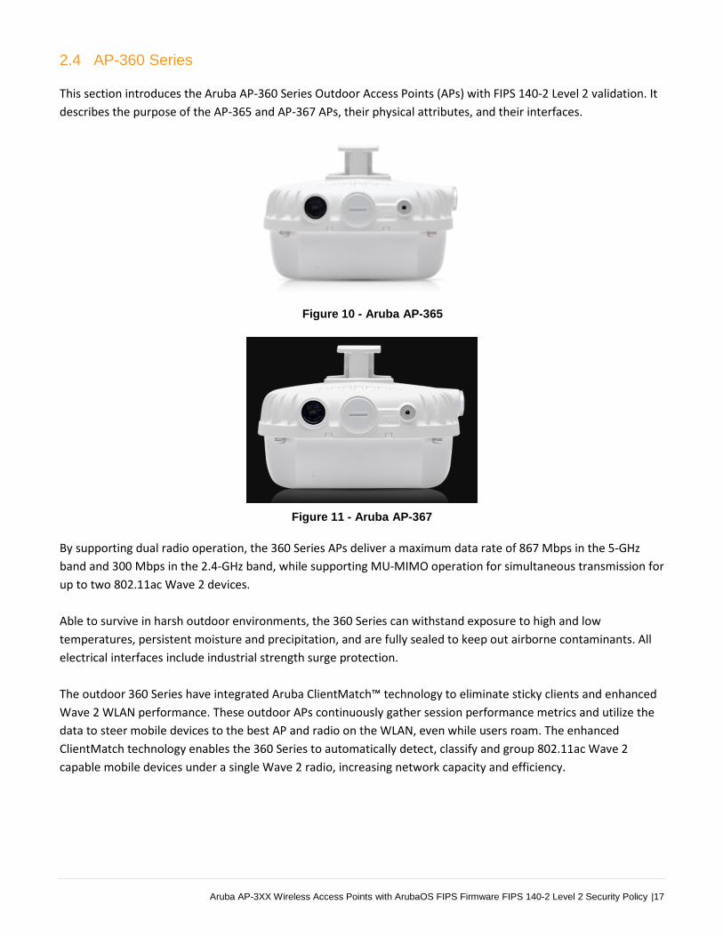
2.4 AP-360 Series
This section introduces the Aruba AP-360 Series Outdoor Access Points (APs) with FIPS 140-2 Level 2 validation. It
describes the purpose of the AP-365 and AP-367 APs, their physical attributes, and their interfaces.
Figure 10 - Aruba AP-365
Figure 11 - Aruba AP-367
By supporting dual radio operation, the 360 Series APs deliver a maximum data rate of 867 Mbps in the 5-GHz
band and 300 Mbps in the 2.4-GHz band, while supporting MU-MIMO operation for simultaneous transmission for
up to two 802.11ac Wave 2 devices.
Able to survive in harsh outdoor environments, the 360 Series can withstand exposure to high and low
temperatures, persistent moisture and precipitation, and are fully sealed to keep out airborne contaminants. All
electrical interfaces include industrial strength surge protection.
The outdoor 360 Series have integrated Aruba ClientMatch™ technology to eliminate sticky clients and enhanced
Wave 2 WLAN performance. These outdoor APs continuously gather session performance metrics and utilize the
data to steer mobile devices to the best AP and radio on the WLAN, even while users roam. The enhanced
ClientMatch technology enables the 360 Series to automatically detect, classify and group 802.11ac Wave 2
capable mobile devices under a single Wave 2 radio, increasing network capacity and efficiency.

18| Aruba AP-3XX Wireless Access Points with ArubaOS FIPS Firmware FIPS 140-2 Level 2 Security Policy
2.4.1 Physical Description The Aruba AP-365 and AP-367 Access Points are multi-chip standalone cryptographic modules consisting of
hardware and software, all contained in hard, opaque plastic cases. Each module contains 802.11 a/b/g/n/ac
transceivers and support four omni-directional internal antennas for the AP-365, and four directional internal
antennas for the AP-367.
The case physically encloses the complete set of hardware and software components and represents the
cryptographic boundary of the module.
The AP-360 Series Access Points configuration validated during the cryptographic modules testing included:
AP-365 HW: Aruba AP-365-F1 (US) FIPS/TAA (HPE SKU JX969A)
AP-367 HW: Aruba AP-367-F1 (US) FIPS/TAA (HPE SKU JX976A)
2.4.2 Dimensions/Weight The AP-360 Series have the following physical dimensions (unit, excluding mount accessories):
Dimensions: 165 mm (W) x 165 mm (D) x 110 mm (H) / 6.5” (W) x 6.5” (D) x 4.3” (H)
Weight: AP-365: 807 g (1.78 lbs) / AP-367: 815 g (1.80 lbs)
2.4.3 Environmental
Operating: o Temperature: -40° C to +55° C (-40° F to +131° F) o Humidity: 5% to 95% non-condensing
Storage and transportation: o Temperature: -40° C to +70° C (-40° F to +158° F) o Humidity: 5% to 95% non-condensing
2.4.4 Interfaces Each module provides the following network interfaces:
ENET/PoE: One Ethernet network interface (RJ-45, Auto-sensing link speed 10/100/1000BASE-T) o 802.3az Energy Efficient Ethernet (EEE) o PoE-PD: 48 VDC (nominal) 802.3af POE
Figure 12 - Aruba AP-360 Series Outdoor Access Point – Interfaces (with weatherproof caps)

Aruba AP-3XX Wireless Access Points with ArubaOS FIPS Firmware FIPS 140-2 Level 2 Security Policy |19
Antenna interfaces:
• 802.11a/b/g/n/ac four internal antenna (AP-365) or four internal antenna (AP-367)
Bluetooth Low Energy (BLE) radio
Other Interfaces:
Visual indicator (one multi-color LED on front): for System and Radio status
Reset button: factory reset (during device power up)
Serial console interface (micro-USB; adapter cable included in package; disabled in FIPS mode)
Grounding Point
Table 4 - AP-360 Series Status Indicator LEDs
LED Type Color/State Meaning
System Status
(during Boot Up)
Off No power to AP
Red Initial power-up
Green - Flashing Device booting; not ready
Green - Solid Device ready in 1000Mbps mode
(LED turns off after 1200 seconds)
Green / Amber
Alternating, 6 seconds
period
Device ready in 1000Mbps mode
(LED turns off after 1200 seconds)
System Status
(during Operation)
Red - Solid General Fault
Red – 1 blink off every 3
seconds Radio 0 fault (5 GHz)
Red – 2 quick blinks off
0.5 seconds apart
cycled every 3 seconds
Radio 1 fault (2.4 GHz)

20| Aruba AP-3XX Wireless Access Points with ArubaOS FIPS Firmware FIPS 140-2 Level 2 Security Policy
3. Module Objectives
This section describes the assurance levels for each of the areas described in the FIPS 140-2 Standard.
3.1. Security Levels
The Aruba AP-304, AP-305, AP-314, AP-315, AP-334, AP-335, AP-365, and AP-367 Wireless Access Points and
associated modules are intended to meet overall FIPS 140-2 Level 2 requirements as shown in the following table.
Table 5 - Intended Level of Security
Section Section Title Security Level
1 Cryptographic Module Specification 2
2 Cryptographic Module Ports and Interfaces 2
3 Roles, Services, and Authentication 2
4 Finite State Model 2
5 Physical Security 2
6 Operational Environment N/A
7 Cryptographic Key Management 2
8 EMI/EMC 2
9 Self-Tests 2
10 Design Assurance 2
11 Mitigation of Other Attacks N/A
Overall Overall module validation level 2
Aruba AP-3XX Wireless Access Points with ArubaOS FIPS Firmware FIPS 140-2 Level 2 Security Policy |21
4. Physical Security
The Aruba Wireless Access Point is a scalable, multi-processor standalone network device and is enclosed in a
hard, opaque plastic case. The AP enclosure is resistant to probing (please note that this feature has not been
validated as part of the FIPS 140-2 validation) and is opaque within the visible spectrum. The enclosure of the AP
has been designed to satisfy FIPS 140-2 Level 2 physical security requirements.
The Aruba AP-304, AP-305, AP-314, AP-315, AP-334, AP-335, AP-365, and AP-367 Wireless Access Points
require Tamper-Evident Labels (TELs) to allow the detection of the opening of the device and to block the Serial
console port (on the bottom of the device).
To protect the Aruba AP-304, AP-305, AP-314, AP-315, AP-334, AP-335, AP-365, and AP-367 Wireless Access
Points from any tampering with the product, TELs should be applied by the Crypto Officer as covered under section
12, Tamper-Evident Labels.
5. Operational Environment
The operational environment is non-modifiable. The control plane Operating System (OS) is Linux, a real-time,
multi-threaded operating system that supports memory protection between processes. Access to the underlying
Linux implementation is not provided directly. Only Aruba Networks provided interfaces are used, and the
Command Line Interface (CLI) is a restricted command set. The module only allows the loading of trusted and
verified firmware that is signed by Aruba. Any firmware loaded into this module that is not shown on the module
certificate is out of the scope of this validation and requires a separate FIPS 140-2 validation.
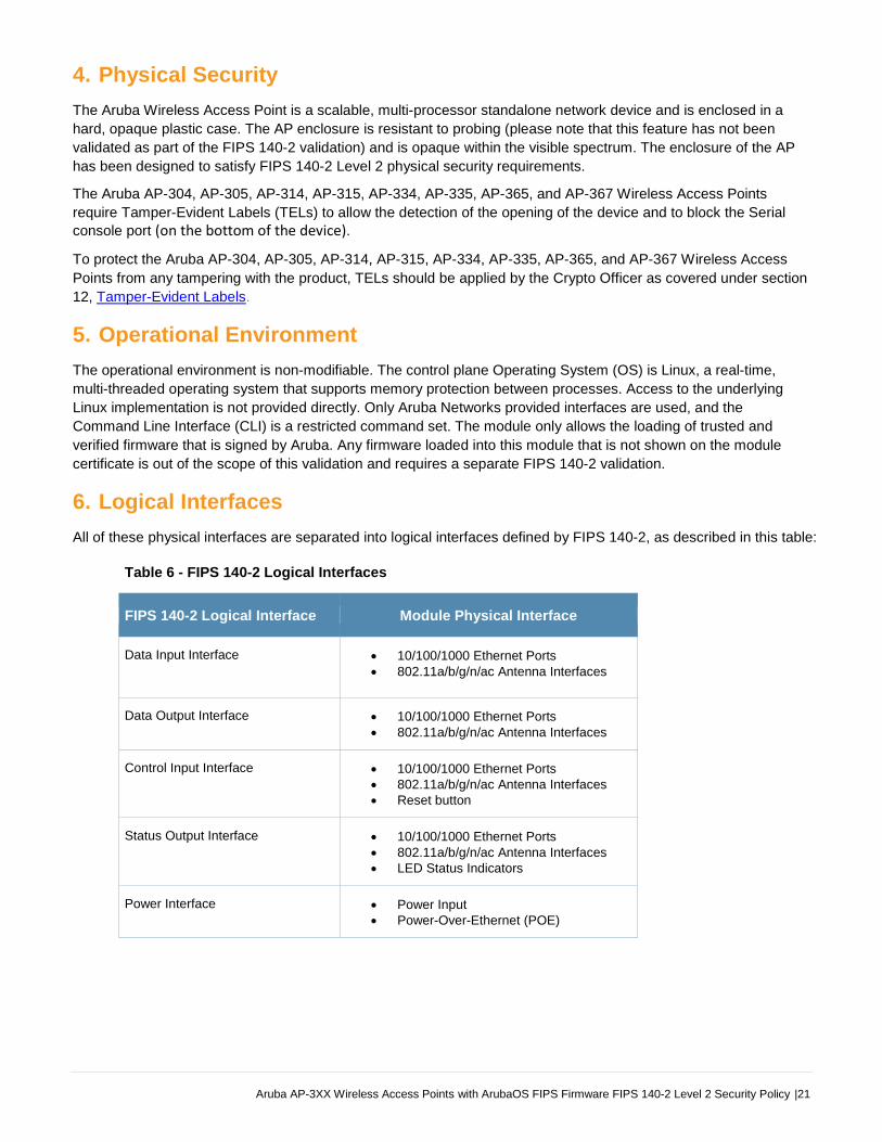
6. Logical Interfaces
All of these physical interfaces are separated into logical interfaces defined by FIPS 140-2, as described in this table:
Table 6 - FIPS 140-2 Logical Interfaces
FIPS 140-2 Logical Interface Module Physical Interface
Data Input Interface 10/100/1000 Ethernet Ports 802.11a/b/g/n/ac Antenna Interfaces
Data Output Interface 10/100/1000 Ethernet Ports 802.11a/b/g/n/ac Antenna Interfaces
Control Input Interface 10/100/1000 Ethernet Ports 802.11a/b/g/n/ac Antenna Interfaces Reset button
Status Output Interface 10/100/1000 Ethernet Ports 802.11a/b/g/n/ac Antenna Interfaces LED Status Indicators
Power Interface Power Input Power-Over-Ethernet (POE)
22| Aruba AP-3XX Wireless Access Points with ArubaOS FIPS Firmware FIPS 140-2 Level 2 Security Policy
Data input and output, control input, status output, and power interfaces are defined as follows:
Data input and output are the packets that use the networking functionality of the module.
Control input consists of manual control inputs for power and reset through the power interfaces (power supply or POE). It also consists of all of the data that is entered into the access point while using the management interfaces. A reset button is present which is used to reset the AP to factory default settings.
Status output consists of the status indicators displayed through the LEDs, the status data that is output from the module while using the management interfaces, and the log file.
o LEDs indicate the physical state of the module, such as power-up (or rebooting), utilization level, and activation state. The log file records the results of self-tests, configuration errors, and monitoring data.
The module may be powered by an external power supply. Operating power may also be provided via a Power Over Ethernet (POE) device, when connected, the power is provided through the connected Ethernet cable.
The Console port is disabled when operating in FIPS mode by a TEL.
The module distinguishes between different forms of data, control, and status traffic over the network ports by
analyzing the packets header information and contents.
7. Roles, Authentication and Services
7.1 Roles
The module supports the role-based authentication of Crypto Officer, User, and Wireless Client; no additional roles
(e.g., Maintenance) are supported. Administrative operations carried out by the Aruba Mobility Controller or Aruba
Mobility Master map to the Crypto Officer role. The Crypto Officer has the ability to configure, manage, and monitor
the module, including the configuration, loading, and zeroization of CSPs. Configuration can be performed through
a standalone Mobility Controller or by a Mobility Master if deployed in the environment. The Mobility master also
acts as a CO for the APs.
Defining characteristics of the roles depend on whether the module is configured as in either Remote AP FIPS
mode, Control Plane Security (CPSec) Protected AP FIPS mode or Mesh AP FIPS Mode. There are four FIPS
approved modes of operations, which are Remote AP FIPS mode, Control Plane Security (CPSec) Protected AP
FIPS mode and the two Mesh Modes, Mesh Portal FIPS Mode and Mesh Point FIPS Mode. Please refer to section
13, Secure Operation in this documentation for more information.
Remote AP FIPS mode:
o Crypto Officer role: the Crypto Officer is the Aruba Mobility Controller or Mobility Master that has the
ability to configure, manage, and monitor the module, including the configuration, loading, and
zeroization of CSPs.
o User role: in the configuration, the User operator shares the same services and authentication
techniques as the Mobility Controller in the Crypto Officer role.
o Wireless Client role: in Remote AP FIPS mode configuration, a wireless client can create a connection
to the module using 802.11i and access wireless network access/bridging services. When Remote AP
cannot communicate with the controller, the wireless client role authenticates to the module via 802.11i
Pre-shared secret only.
Aruba AP-3XX Wireless Access Points with ArubaOS FIPS Firmware FIPS 140-2 Level 2 Security Policy |23
CPSec Protected AP FIPS mode:
o Crypto Officer role: the Crypto Officer is the Aruba Mobility Controller or Mobility Master that has the
ability to configure, manage, and monitor the module, including the configuration, loading, and
zeroization of CSPs.
o User role: in the configuration, the User operator shares the same services and authentication
techniques as the Mobility Controller in the Crypto Officer
o Wireless Client role: in CPSec Protected AP FIPS mode configuration, a wireless client can create a
connection to the module using 802.11i Pre-shared secret and access wireless network access services.
Mesh Portal FIPS mode:
o Crypto Officer role: the Crypto Officer is the Aruba Mobility Controller or Mobility Master that has the
ability to configure, manage, and monitor the module, including the configuration, loading, and
zeroization of CSPs.
o User role: the adjacent Mesh Point APs in a given mesh cluster. Please notice that Mesh Portal AP must
be physically wired to Mobility Controller.
o Wireless Client role: in Mesh Portal FIPS AP configuration, a wireless client can create a connection to
the module using WPA2 and access wireless network access services.
Mesh Point FIPS mode:
o Crypto Officer role: the Crypto Officer role is the Aruba Mobility Controller or Mobility Master that has
the ability to configure, manage, and monitor the module, including the configuration, loading, and
zeroization of CSPs. The first mesh AP configured is the only AP with the direct wired connection.
o User role: the adjacent Mesh APs in a given mesh cluster. Please notice that User role can be a Mesh
Point AP or a Mesh Portal AP in the given mesh network.
o Wireless Client role: in Mesh Mesh Point FIPS AP configuration, a wireless client can create a
connection to the module using WPA2 and access wireless network access services.
7.2 Authentication
7.2.1 Crypto Officer Authentication In each of FIPS approved modes, the Aruba Mobility Controller or Mobility Master implements the Crypto Officer
role. Connections between the module and the mobility controller are protected using IPSec. Crypto Officer’s
authentication is accomplished via either Pre-shared secret (IKEv1), RSA digital certificate (IKEv1/IKEv2) or
ECDSA digital certificate (IKEv2). The Mobility Master interacts with the APs through the Mobility Controller through
provisioning of configurations.
7.2.2 User Authentication Authentication for the User role depends on the module configuration. When the module is configured in Mesh
Portal FIPS mode or Mesh Point FIPS mode, the User role is authenticated via the WPA2 pre-shared key or EAP.
When the module is configured as a Remote AP FIPS mode and CPSec protected AP FIPS mode, the User role is
authenticated via the same IKEv1 pre-shared key or RSA/ECDSA certificate that is used by the Crypto Officer.
7.2.3 Wireless Client Authentication The wireless client role defined in each of FIPS approved modes authenticates to the module via 802.11i. Please
notice that WEP and TKIP configurations are not permitted in FIPS mode. When Remote AP cannot communicate
with the controller, the wireless client role authenticates to the module via 802.11i Pre-shared secret only.

24| Aruba AP-3XX Wireless Access Points with ArubaOS FIPS Firmware FIPS 140-2 Level 2 Security Policy
7.2.4 Strength of Authentication Mechanisms
The following table describes the relative strength of each supported authentication mechanism.
Table 7 - Strength of Authentication Mechanisms
Authentication Type Role(s) Mechanism Strength
IKEv1 Pre-shared secret based authentication
Crypto Officer and User
Passwords are required to be a minimum of eight ASCII characters and a maximum of 64 with a minimum of one letter and one number, or the password must be exactly 64 HEX characters. Assuming the weakest option of 8 ASCII characters with the listed restrictions, the probability of randomly guessing the correct sequence is one (1) in 3,608,347,333,959,680 (this calculation is based on the assumption that the typical standard American QWERTY computer keyboard has 10 Integer digits, 52 alphabetic characters, and 32 special characters providing 94 characters to choose from in total. The calculation should be 94^8 (Total number of 8-digit passwords) – 84^8 (Total number of 8-digit passwords without numbers) – 42^8 (Total number of 8-digit passwords without letters) + 32^8 (Total number of 8-digit passwords without letters or numbers, added since it’s double-counted in the previous two subtractions) = 3,608,347,333,959,680). At optimal network conditions (assuming 1ms round-trip latency), an attacker would only get 60,000 guesses per minute. Therefore the associated probability of a successful random attempt during a one-minute period is 60,000/3,608,347,333,959,680, which is less than 1 in 100,000 required by FIPS 140-2.
802.11i Pre-shared secret based authentication
Wireless Client and Mesh AP User
Passwords are required to be a minimum of eight ASCII characters and a maximum of 63 with a minimum of one letter and one number, or the password must be exactly 64 HEX characters. Assuming the weakest option of 8 ASCII characters with the listed restrictions, the probability of randomly guessing the correct sequence is one (1) in 3,608,347,333,959,680 (this calculation is based on the assumption that the typical standard American QWERTY computer keyboard has 10 Integer digits, 52 alphabetic characters, and 32 special characters providing 94 characters to choose from in total. The calculation should be 94^8 (Total number of 8-digit passwords) – 84^8 (Total number of 8-digit passwords without numbers) – 42^8 (Total number of 8-digit passwords without letters) + 32^8 (Total number of 8-digit passwords without letters or numbers, added since it is double-counted in the previous two subtractions) = 3,608,347,333,959,680). At optimal network conditions (assuming 1ms round-trip latency), an attacker would only get 60,000 guesses per minute. Therefore the associated probability of a successful random attempt during a one-minute period is 60,000/3,608,347,333,959,680, which is less than 1 in 100,000 required by FIPS 140-2.
RSA Certificate based authentication
Crypto Officer and User
The module supports 2048-bit RSA key authentication during IKEv1 and IKEv2. RSA 2048 bit keys correspond to 112 bits of security. Assuming the low end of that range, the associated probability of a successful random attempt is 1 in 2^112, which is less than 1 in 1,000,000 required by FIPS 140-2. At optimal network conditions (assuming 1ms round-trip latency), an attacker would only get 60,000 guesses per minute. Therefore the associated probability of a successful random attempt during a one-minute period is 60,000/2^112, which is less than 1 in 100,000 required by FIPS 140-2.
Aruba AP-3XX Wireless Access Points with ArubaOS FIPS Firmware FIPS 140-2 Level 2 Security Policy |25
ECDSA Certificate based authentication
Crypto Officer and User
ECDSA signing and verification is used to authenticate to the module during IKEv1/IKEv2. Both P-256 and P-384 curves are supported. ECDSA P-256 provides 128 bits of equivalent security, and P-384 provides 192 bits of equivalent security. Assuming the low end of that range, the associated probability of a successful random attempt is 1 in 2^128, which is less than 1 in 1,000,000 required by FIPS 140-2. At optimal network conditions (assuming 1ms round-trip latency), an attacker would only get 60,000 guesses per minute. Therefore the associated probability of a successful random attempt during a one-minute period is 60,000/2^128, which is less than 1 in 100,000 required by FIPS 140-2.
7.3 Services The module provides various services depending on role. These are described below.
7.3.1 Crypto Officer Services
See the table below for descriptions of the services available to the Crypto Officer role. The services are the same
in each of the four (4) FIPS approved modes of operation.
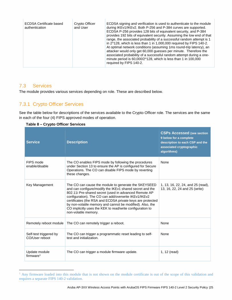
Table 8 – Crypto Officer Services
Service Description
CSPs Accessed (see section
9 below for a complete
description to each CSP and the
associated cryptographic
algorithms)
FIPS mode enable/disable
The CO enables FIPS mode by following the procedures under Section 13 to ensure the AP is configured for Secure Operations. The CO can disable FIPS mode by reverting these changes.
None
Key Management The CO can cause the module to generate the SKEYSEED and can configure/modify the IKEv1 shared secret and the 802.11i Pre-shared secret (used in advanced Remote AP configuration). The CO can add/overwrite IKEv1/IKEv2 certificates (the RSA and ECDSA private keys are protected by non-volatile memory and cannot be modified). Also, the CO implicitly uses the KEK to read/write configuration to non-volatile memory.
1, 13, 16, 22, 24, and 25 (read), 13, 16, 22, 24 and 25 (write)
Remotely reboot module The CO can remotely trigger a reboot. None
Self-test triggered by CO/User reboot
The CO can trigger a programmatic reset leading to self-test and initialization.
None
Update module firmware1
The CO can trigger a module firmware update. 1, 12 (read)
1 Any firmware loaded into this module that is not shown on the module certificate is out of the scope of this validation and requires a separate FIPS 140-2 validation.

26| Aruba AP-3XX Wireless Access Points with ArubaOS FIPS Firmware FIPS 140-2 Level 2 Security Policy
Configure non-security related module parameters
CO can configure various operational parameters that do not relate to security.
None
Creation/use of secure management session between module and CO2
The module supports use of IPSec for securing the management channel.
2, 3, 4, 5, 6, 7, 8, 9, 10, 11 (read, write)
12 (read)
13, 14, 15, 16, 17, 18, 19, 20, 21, 22, 23, 24 (read, write)
System Status CO may view system status information through the secured management channel.
See creation/use of secure management session above.
Creation/use of secure mesh channel3
The module requires secure connections between mesh points using 802.11i.
1, 25 (read)
26, 27, 28, 29, 30 (read/write)
Openflow Agent Agent run on device for use with Mobility Master SDN. Leveraged by the SDN for discovering of hosts and networks, configuration of networks, and collection of statistics.
None
Zeroization The cryptographic keys stored in SDRAM memory can be zeroized by rebooting the module. The cryptographic keys (IKEv1 Pre-shared key and 802.11i Pre-Shared Key) stored in the flash can be zeroized by using command ‘ap wipe out flash’ or by overwriting with a new secret. The ‘no’ command in the CLI can be used to zeroize IKE, IPSec CSPs. Please See CLI guide for details. The other keys/CSPs (RSA/ECDSA public key/private key and certificate) stored in Flash memory can be zeroized by using command ‘ap wipe out flash’.
All CSPs (not including the Factory CA Public Key) will be destroyed.
7.3.2 User Services
The User role for Remote AP FIPS mode and Control Plane Security (CPSec) Protected AP FIPS mode supports
the same services listed in the Section 7.3.1 Crypto Officer Services.
The User role for Mesh Portal FIPS mode and Mesh Point FIPS mode supports the services listed in Section 7.3.3
Wireless Client Services.
7.3.3 Wireless Client Services The following module services are provided for the Wireless Client role in Remote AP FIPS mode, CPSec protected
AP FIPS mode, Mesh Portal FIPS mode and Mesh Point FIPS mode.
2 This service is not available in Mesh Point mode. In Mesh Point mode, the IPSec tunnel will be between the Mesh Portal and the controller, not the Mesh Point and the controller.3 This service is only applicable in the Mesh Portal mode and Mesh Point mode. It is not applicable in Control Plane Security (CPSec) Protected AP FIPS mode and Remote AP FIPS mode.

Aruba AP-3XX Wireless Access Points with ArubaOS FIPS Firmware FIPS 140-2 Level 2 Security Policy |27
Table 9 - Wireless Client Services
Service Description
CSPs Accessed (see section 9
below for a complete description to
each CSP and the associated
cryptographic algorithms)
Generation and use of 802.11i cryptographic keys
In all FIPS modes, the links between the module and wireless client are secured with 802.11i.
1, 25 (read)
26, 27, 28, 29, 30 (read/write)
Use of 802.11i Pre-shared secret for establishment of IEEE 802.11i keys
When the module is in advanced Remote AP configuration, the links between the module and the Wireless Client are secured with 802.11i. This is authenticated with a shared secret only.
1, 25 (read)
Wireless bridging services
The module bridges traffic between the wireless client and the wired network.
None
7.3.4 Unauthenticated Services
The module provides the following unauthenticated services, which are available regardless of role.
System status – module LEDs
Reboot module by removing/replacing power
Self-test and initialization at power-on.
7.3.5 Services Available in Non-FIPS Mode
The following services are available in Non-FIPS mode:
All of the services that are available in FIPS mode are also available in non-FIPS mode.
If not operating in the Approved mode as per the procedures in sections 13.1, Crypto Officer Management, 13.4, Setting Up Your Wireless Access Point and 13.5, Enabling FIPS Mode on the Staging Controller, then non-Approved algorithms and/or sizes are available.
Upgrading the firmware via the console port (non-Approved).
Debugging via the console port (non-Approved).
For additional non-security-relevant services offered by the module, please refer to the ArubaOS User Guide listed
in section 13.7.
7.3.6 Non-Approved Services Non-Approved in FIPS Mode The Suite-B (bSec) protocol is a pre-standard protocol that has been proposed to the IEEE 802.11
committee as an alternative to 802.11i.
WPA3
WPA-2 Multiple Pre-Shared Key (MPSK), where every client connected to the WLAN SSID may have its
own unique PSK.
IPSec/IKE using Triple-DES
Remote AP Termination on Mobility Master Virtual Appliance

28| Aruba AP-3XX Wireless Access Points with ArubaOS FIPS Firmware FIPS 140-2 Level 2 Security Policy
8. Cryptographic Algorithms
8.1. FIPS Approved Algorithms
The firmware in each module contains the following cryptographic algorithm implementations/crypto libraries to
implement the different FIPS approved cryptographic algorithms that will be used for the corresponding security
services supported by the module in FIPS mode:
Note that not all algorithm modes that appear on the module’s CAVP certificates are utilized by the module,
and the tables below list only the algorithm modes that are utilized by the module.
ArubaOS OpenSSL Module algorithm implementation
ArubaOS Crypto Module algorithm implementation
ArubaOS UBOOT Bootloader algorithm implementation
Aruba AP Hardware algorithm implementation
Below are the detailed lists for the FIPS approved algorithms and the associated certificates implemented by each
algorithm implementation.
Table 10 - ArubaOS OpenSSL Module CAVP Certificates
ArubaOS OpenSSL Module
CAVP
Certificate # Algorithm Standard Mode/Method
Key Lengths,
Curves, Moduli Use
5266 AES FIPS 197,
SP 800-38A
ECB, CBC, CTR
(192, 256, ext
only, encryption
only)
128, 192, 256 Data Encryption/Decryption
1738 CVL4
IKEv1
SP 800-135
Rev1 IKEv1: DSA, PSK
IKEv1: DH 2048-
bit; SHA-256,
SHA-384
Key Derivation
C2091CVL
IKEv1
SP 800-135
Rev1 IKEv1 IKEv1: SHA-1 Key Derivation
2017 DRBG SP 800-90A AES CTR 256 Deterministic Random Bit
Generation
1375 ECDSA 186-4 PKG, SigGen,
SigVer P256, P384
Digital Key Generation,
Signature Generation and
Verification
3485 HMAC FIPS 198-1
HMAC-SHA-1,
HMAC-SHA-256,
HMAC-SHA-384,
HMAC-SHA-512
Key Size < Block
Size Message Authentication
C2091 HMAC FIPS 198-1 HMAC-SHA-1 Key Size < Block
Size Message Authentication
181 KBKDF SP 800-108 CTR
HMAC-SHA-1,
HMAC-SHA-256,
HMAC-SHA-384 Deriving Keys
4 IKEv1 protocol has not been reviewed or tested by the CAVP and CMVP.
Aruba AP-3XX Wireless Access Points with ArubaOS FIPS Firmware FIPS 140-2 Level 2 Security Policy |29
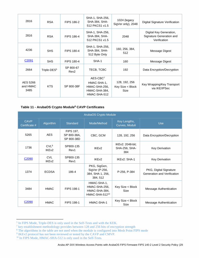
2816 RSA FIPS 186-2
SHA-1, SHA-256,
SHA-384, SHA-
512 PKCS1 v1.5
1024 (legacy
SigVer only), 2048 Digital Signature Verification
2816 RSA FIPS 186-4
SHA-1, SHA-256,
SHA-384, SHA-
512 PKCS1 v1.5 2048
Digital Key Generation,
Signature Generation and
Verification
4236 SHS FIPS 180-4
SHA-1, SHA-256,
SHA-384, SHA-
512 Byte Only
160, 256, 384,
512 Message Digest
C2091 SHS FIPS 180-4 SHA-1 160 Message Digest
2664 Triple-DES5SP 800-67
Rev2 TECB, TCBC 192 Data Encryption/Decryption
AES 5266
and HMAC
3485
KTS SP 800-38F
AES-CBC7
HMAC-SHA-1,
HMAC-SHA-256,
HMAC-SHA-384,
HMAC-SHA-512
128, 192, 256
Key Size < Block
Size
Key Wrapping/Key Transport
via IKE/IPSec
Table 11 - ArubaOS Crypto Module8 CAVP Certificates
ArubaOS Crypto Module
CAVP
Certificate # Algorithm Standard Mode/Method
Key Lengths,
Curves, Moduli Use
5265 AES FIPS 197,
SP 800-38A,
SP 800-38D CBC, GCM 128, 192, 256 Data Encryption/Decryption
1736 CVL9
IKEv2
SP800-135
Rev1 IKEv2
IKEv2: 2048-bit;
SHA-256, SHA-
384
Key Derivation
C2090 CVL
IKEv2
SP800-135
Rev1 IKEv2 IKEv2: SHA-1 Key Derivation
1374 ECDSA 186-4
PKG, SigGen,
SigVer (P-256,
384, SHA 1, 256,
384, 512
P-256, P-384 PKG, Digital Signature
Generation and Verification
3484 HMAC FIPS 198-1
HMAC-SHA-1,
HMAC-SHA-256,
HMAC-SHA-384,
HMAC-SHA-51210
Key Size < Block
Size Message Authentication
C2090 HMAC FIPS 198-1 HMAC-SHA-1 Key Size < Block
Size Message Authentication
5 In FIPS Mode, Triple-DES is only used in the Self-Tests and with the KEK. 7 key establishment methodology provides between 128 and 256 bits of encryption strength 8 The algorithms in the table are not used when the module is configured into Mesh Point FIPS mode9 IKEv2 protocol has not been reviewed or tested by the CAVP and CMVP. 10 In FIPS Mode, HMAC-SHA-512 is only used in the Self-Tests.

30| Aruba AP-3XX Wireless Access Points with ArubaOS FIPS Firmware FIPS 140-2 Level 2 Security Policy
2815 RSA FIPS 186-2
SHA-1, SHA2-
256, SHA2-384,
SHA-512 PKCS1
v1.5
1024 (legacy
SigVer only), 2048 Digital Signature Verification
2815 RSA FIPS 186-4
SHA-1, SHA2-
256, SHA2-384,
SHA-512 PKCS1
v1.5
2048, 1024 (for
legacy SigVer
only)
Key Generation, Digital
Signature Generation and
Verification
4235 SHS FIPS 180-4
SHA-1, SHA-256,
SHA-384, SHA-
51211 Byte Only
160, 256, 384,
512 Message Digest
C2090 SHS FIPS 180-4 SHA-1 160 Message Digest
2663 Triple-DES12 SP 800-67
Rev2 TCBC 192 Data Encryption/Decryption
AES 5265 KTS SP 800-38F AES-GCM13 128, 256 Key Wrapping/Key Transport
via IKE/IPSec
AES 5265
HMAC 3484 KTS SP 800-38F
AES-CBC14
HMAC-SHA-1,
HMAC-SHA-256,
HMAC-SHA-384,
HMAC-SHA-51215
128, 192, 256
Key Size < Block
Size
Key Wrapping/Key Transport
via IKE/IPSec
Table 12 - ArubaOS UBOOT Bootloader CAVP Certificates
ArubaOS UBOOT Bootloader
CAVP
Certificate # Algorithm Standard Mode/Method
Key Lengths,
Curves, Moduli Use
2395
3111 RSA FIPS 186-4 SHA-1, SHA2-256 2048
Digital Signature
Verification
3633
4685 SHS FIPS 180-4
SHA-1, SHA-256
Byte Only Message Digest
Note:
Only Firmware signed with SHA-256 is permitted in the Approved mode. Digital signature verification with
SHA-1, while available within the module, shall only be used while in the non-Approved mode.
11 In FIPS Mode, HMAC-SHA-512 is only used in the Self-Tests. 12 In FIPS Mode, Triple-DES is only used in the Self-Tests. 13 key establishment methodology provides 128 or 256 bits of encryption strength14 key establishment methodology provides between 128 and 256 bits of encryption strength 15 In FIPS Mode, HMAC-SHA-512 is only used in the Self-Tests.

Aruba AP-3XX Wireless Access Points with ArubaOS FIPS Firmware FIPS 140-2 Level 2 Security Policy |31
Table 13 – Aruba AP Hardware CAVP Certificates
Aruba AP Hardware
CAVP
Certificate # Algorithm Standard Mode/Method
Key Lengths,
Curves, Moduli Use
5412
5664AES
FIPS 197,
SP 800-38A,
SP 800-38C
ECB, CCM, GCM
(used for self-test
only)
128, 256 Data Encryption/Decryption
8.2. Non-FIPS Approved Algorithms Allowed in FIPS Mode
NDRNG (used solely to seed the Approved DRBG)
Diffie-Hellman (key agreement; key establishment methodology provides 112 bits of encryption strength)
EC Diffie-Hellman (key agreement; key establishment methodology provides 128 or 192 bits of encryption strength)
8.3. Non-FIPS Approved Algorithms used only in Non-FIPS 140 Mode The cryptographic module implements the following non-approved algorithms that are not permitted for use, and
are not used, in the FIPS 140-2 mode of operations:
DES
HMAC-MD5
MD5
RC4
RSA (non-compliant less than 112 bits of encryption strength)
Null Encryption (Disallowed by Policy)
Triple-DES as used in IKE/IPSec (Non-Approved by Policy)
Note: DES, MD5, HMAC-MD5 and RC4 are used for older versions of WEP in non-FIPS mode.
32| Aruba AP-3XX Wireless Access Points with ArubaOS FIPS Firmware FIPS 140-2 Level 2 Security Policy
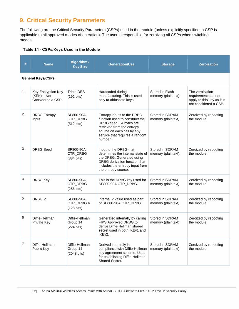
9. Critical Security Parameters
The following are the Critical Security Parameters (CSPs) used in the module (unless explicitly specified, a CSP is
applicable to all approved modes of operation). The user is responsible for zeroizing all CSPs when switching
modes.
Table 14 - CSPs/Keys Used in the Module
# Name Algorithm /
Key Size Generation/Use Storage Zeroization
General Keys/CSPs
1 Key Encryption Key (KEK) – Not Considered a CSP
Triple-DES
(192 bits)
Hardcoded during manufacturing. This is used only to obfuscate keys.
Stored in Flash memory (plaintext).
The zeroization requirements do not apply to this key as it is not considered a CSP.
2 DRBG Entropy Input
SP800-90A CTR_DRBG
(512 bits)
Entropy inputs to the DRBG function used to construct the DRBG seed. 64 bytes are retrieved from the entropy source on each call by any service that requires a random number.
Stored in SDRAM memory (plaintext).
Zeroized by rebooting the module.
3 DRBG Seed SP800-90A CTR_DRBG
(384 bits)
Input to the DRBG that determines the internal state of the DRBG. Generated using DRBG derivation function that includes the entropy input from the entropy source.
Stored in SDRAM memory (plaintext).
Zeroized by rebooting the module.
4 DRBG Key SP800-90A CTR_DRBG
(256 bits)
This is the DRBG key used for SP800-90A CTR_DRBG.
Stored in SDRAM memory (plaintext).
Zeroized by rebooting the module.
5 DRBG V SP800-90A CTR_DRBG V
(128 bits)
Internal V value used as part of SP800-90A CTR_DRBG.
Stored in SDRAM memory (plaintext).
Zeroized by rebooting the module.
6 Diffie-Hellman Private Key
Diffie-Hellman Group 14
(224 bits)
Generated internally by calling FIPS Approved DRBG to derive Diffie-Hellman shared secret used in both IKEv1 and IKEv2.
Stored in SDRAM memory (plaintext).
Zeroized by rebooting the module.
7 Diffie-Hellman Public Key
Diffie-Hellman Group 14
(2048 bits)
Derived internally in compliance with Diffie-Hellman key agreement scheme. Used for establishing Diffie-Hellman Shared Secret.
Stored in SDRAM memory (plaintext).
Zeroized by rebooting the module.

Aruba AP-3XX Wireless Access Points with ArubaOS FIPS Firmware FIPS 140-2 Level 2 Security Policy |33
Table 14 - CSPs/Keys Used in the Module
8 Diffie-Hellman Shared Secret
Diffie-Hellman Group 14
(2048 bits)
Established during Diffie-Hellman Exchange. Used for deriving IPSec/IKE cryptographic keys.
Stored in SDRAM memory (plaintext).
Zeroized by rebooting the module.
9 EC Diffie-Hellman Private Key
EC Diffie-Hellman
(Curves: P-256 or P-384)
Generated internally by calling FIPS Approved DRBG during EC Diffie-Hellman Exchange. Used for establishing EC Diffie-Hellman Shared Secret.
Stored in SDRAM memory (plaintext).
Zeroized by rebooting the module.
10 EC Diffie-Hellman Public Key
EC Diffie-Hellman
(Curves: P-256 or P-384)
Derived internally in compliance with EC Diffie-Hellman key agreement scheme. Used for establishing EC Diffie-Hellman Shared Secret.
Stored in SDRAM memory (plaintext).
Zeroized by rebooting the module.
11 EC Diffie-Hellman Shared Secret
EC Diffie-Hellman
(Curves: P-256 or P-384)
Established during EC Diffie-Hellman Exchange. Used for deriving IPSec/IKE cryptographic keys.
Stored in SDRAM memory (plaintext).
Zeroized by rebooting the module.
12 Factory CA Public Key
RSA
(2048 bits)
This is RSA public key. Loaded into the module during manufacturing. Used for Firmware verification.
Stored in TPM. Since this is a public key, the zeroization requirements do not apply.
IPSec/IKE18
13 IKE Pre-shared secret19
Shared secret
(8 - 64 ASCII or 64 HEX characters)
Entered by CO role. Used for IKEv1 peers authentication.
Stored in Flash memory obfuscated with KEK
Zeroized by using command ‘ap wipe out flash’ or by overwriting with a new secret
14 skeyid Shared Secret
(160/256/384 bits)
A shared secret known only to IKEv1 peers. It was established via key derivation function defined in SP800-135 KDF (IKEv1). Used for deriving other keys in IKEv1 protocol implementation.
Stored in SDRAM memory (plaintext)
Zeroized by rebooting the module.
15 skeyid_d Shared Secret
(160/256/384 bits)
A shared secret known only to IKEv1 peers. It was derived via key derivation function defined in SP800-135 KDF (IKEv1). Used for deriving IKEv1 session authentication key.
Stored in SDRAM memory (plaintext)
Zeroized by rebooting the module
18 Not used in Mesh Point modes of operation 19 Applicable only to Remote AP and Mesh Portal modes

34| Aruba AP-3XX Wireless Access Points with ArubaOS FIPS Firmware FIPS 140-2 Level 2 Security Policy
Table 14 - CSPs/Keys Used in the Module
16 SKEYSEED Shared Secret
(160/256/384 bits)
A shared secret known only to IKEv2 peers. It was derived via key derivation function defined in SP800-135 KDF (IKEv2) and it will be used for deriving other keys in IKEv2 protocol.
Stored in SDRAM memory (plaintext).
Zeroized by rebooting the module.
17 IKE Session Authentication Key
HMAC-SHA-1/256/384
(160/256/384 bits)
The IKE session (IKE Phase I) authentication key. This key is derived via key derivation function defined in SP800-135 KDF (IKEv1/IKEv2). Used for IKEv1/IKEv2 payload integrity verification.
Stored in SDRAM memory (plaintext).
Zeroized by rebooting the module.
18 IKE Session Encryption Key
AES (CBC)
(128/192/256 bits)
The IKE session (IKE Phase I) encrypt key. This key is derived via key derivation function defined in SP800-135 KDF (IKEv1/IKEv2). Used for IKE payload protection.
Stored in SDRAM memory (plaintext).
Zeroized by rebooting the module.
19 IPSec Session Encryption Key
AES (CBC)
(128/192/256 bits)
and AES-GCM
(128/256 bits)
The IPSec (IKE phase II) encryption key. This key is derived via a key derivation function defined in SP800-135 KDF (IKEv1/IKEv2). Used for IPSec traffics protection. IPSec session encryption keys can also be used for the Double Encrypt feature.
Stored in SDRAM memory (plaintext).
Zeroized by rebooting the module.
20 IPSec Session Authentication Key
HMAC-SHA-1
(160 bits)
The IPSec (IKE Phase II) authentication key. This key is derived via using the KDF defined in SP800-135 KDF (IKEv1/IKEv2). Used for IPSec traffics integrity verification.
Stored in SDRAM memory (plaintext).
Zeroized by rebooting the module.
21 IKE RSA Private Key
RSA Private Key
(2048 bits)
This is the RSA private key. This key is generated by the module in compliance with FIPS 186-4 RSA key pair generation method. In both IKEv1 and IKEv2, DRBG is called for key generation. It is used for RSA signature signing in either IKEv1 or IKEv2. This key can also be entered by the CO.
Stored in Flash memory obfuscated with KEK.
Zeroized by using command ‘ap wipe out flash’.
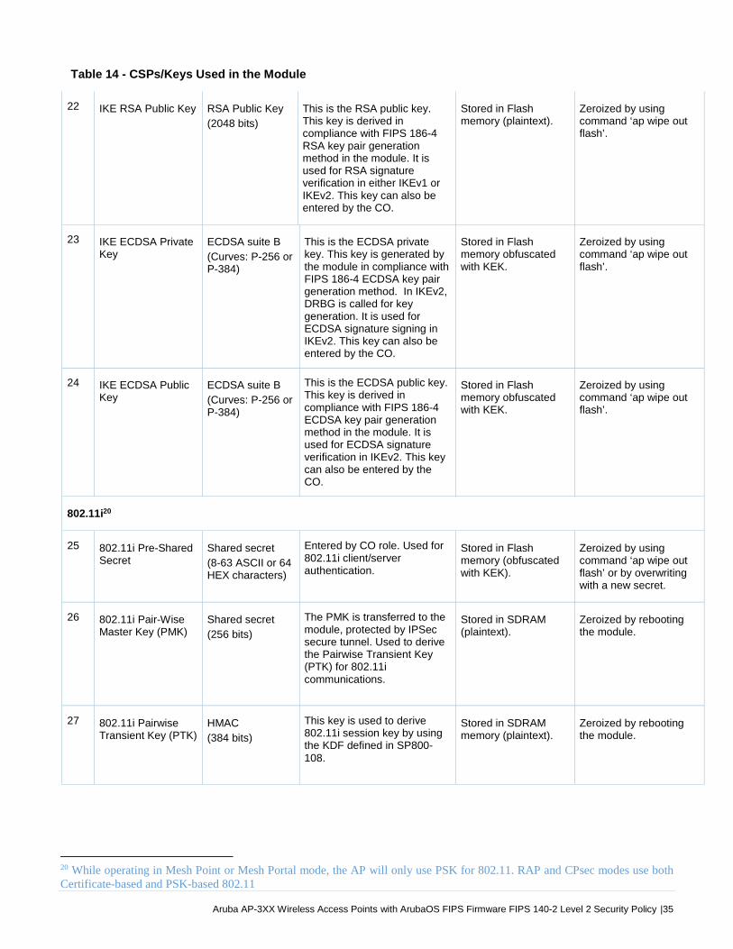
Aruba AP-3XX Wireless Access Points with ArubaOS FIPS Firmware FIPS 140-2 Level 2 Security Policy |35
Table 14 - CSPs/Keys Used in the Module
22 IKE RSA Public Key RSA Public Key
(2048 bits)
This is the RSA public key. This key is derived in compliance with FIPS 186-4 RSA key pair generation method in the module. It is used for RSA signature verification in either IKEv1 or IKEv2. This key can also be entered by the CO.
Stored in Flash memory (plaintext).
Zeroized by using command ‘ap wipe out flash’.
23 IKE ECDSA Private Key
ECDSA suite B
(Curves: P-256 or P-384)
This is the ECDSA private key. This key is generated by the module in compliance with FIPS 186-4 ECDSA key pair generation method. In IKEv2, DRBG is called for key generation. It is used for ECDSA signature signing in IKEv2. This key can also be entered by the CO.
Stored in Flash memory obfuscated with KEK.
Zeroized by using command ‘ap wipe out flash’.
24 IKE ECDSA Public Key
ECDSA suite B
(Curves: P-256 or P-384)
This is the ECDSA public key. This key is derived in compliance with FIPS 186-4 ECDSA key pair generation method in the module. It is used for ECDSA signature verification in IKEv2. This key can also be entered by the CO.
Stored in Flash memory obfuscated with KEK.
Zeroized by using command ‘ap wipe out flash’.
802.11i20
25 802.11i Pre-Shared Secret
Shared secret
(8-63 ASCII or 64 HEX characters)
Entered by CO role. Used for 802.11i client/server authentication.
Stored in Flash memory (obfuscated with KEK).
Zeroized by using command ‘ap wipe out flash’ or by overwriting with a new secret.
26 802.11i Pair-Wise Master Key (PMK)
Shared secret
(256 bits)
The PMK is transferred to the module, protected by IPSec secure tunnel. Used to derive the Pairwise Transient Key (PTK) for 802.11i communications.
Stored in SDRAM (plaintext).
Zeroized by rebooting the module.
27 802.11i Pairwise Transient Key (PTK)
HMAC
(384 bits)
This key is used to derive 802.11i session key by using the KDF defined in SP800-108.
Stored in SDRAM memory (plaintext).
Zeroized by rebooting the module.
20 While operating in Mesh Point or Mesh Portal mode, the AP will only use PSK for 802.11. RAP and CPsec modes use both Certificate-based and PSK-based 802.11

36| Aruba AP-3XX Wireless Access Points with ArubaOS FIPS Firmware FIPS 140-2 Level 2 Security Policy
Table 14 - CSPs/Keys Used in the Module
28 802.11i Session Key
AES-CCM
(128 bits)
Derived during 802.11i 4-way handshake by using the KDF defined in SP800-108 then used as the session key.
Stored in SDRAM memory (plaintext).
Zeroized by rebooting the module.
29 802.11i Group Master Key (GMK)
Shared secret
(256 bits)
Generated by calling DRBG. Used to derive 802.11i Group Transient Key GTK.
Stored in SDRAM memory (plaintext)
Zeroized by rebooting the module
30 802.11i Group Transient Key (GTK)
AES-CCM
(256 bits)
Derived from 802.11 GMK by using the KDF defined in SP800-108. The GTK is the 802.11i session key used for broadcast communications protection.
Stored in SDRAM memory (plaintext)
Zeroized by rebooting the module
Notes:
AES GCM IV generation is performed in compliance with the Implementation Guidance A.5 scenario 1. FIPS approved DRBG (Cert. #2017) is used for IV generation and 96 bits of IV is supported.
For keys identified as being “Generated internally by calling FIPS approved DRBG", the generated seed used in the asymmetric key generation is an unmodified output from the DRBG.
The module generates a minimum of 256 bits of entropy for use in key generation.
In Remote AP FIPS mode, all CSPs are applicable.
In CPSec Protected AP FIPS mode, the IKEv1 PSK CSPs are not applicable.
In Mesh Point FIPS modes, all IPSec/IKE CSPs are not applicable.
CSPs labeled as “Entered by CO” are transferred into the module from the Mobility Controller via IPSec.
CSPs generated in FIPS mode cannot be used in non-FIPS mode, and vice versa.
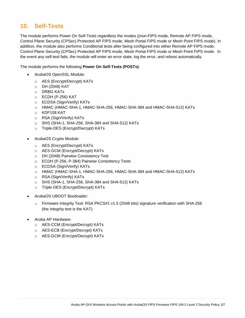
Aruba AP-3XX Wireless Access Points with ArubaOS FIPS Firmware FIPS 140-2 Level 2 Security Policy |37
10. Self-Tests
The module performs Power On Self-Tests regardless the modes ((non-FIPS mode, Remote AP FIPS mode,
Control Plane Security (CPSec) Protected AP FIPS mode, Mesh Portal FIPS mode or Mesh Point FIPS mode). In
addition, the module also performs Conditional tests after being configured into either Remote AP FIPS mode,
Control Plane Security (CPSec) Protected AP FIPS mode, Mesh Portal FIPS mode or Mesh Point FIPS mode. In
the event any self-test fails, the module will enter an error state, log the error, and reboot automatically.
The module performs the following Power On Self-Tests (POSTs):
ArubaOS OpenSSL Module:
o AES (Encrypt/Decrypt) KATs
o DH (2048) KAT
o DRBG KATs
o ECDH (P-256) KAT
o ECDSA (Sign/Verify) KATs
o HMAC (HMAC-SHA-1, HMAC-SHA-256, HMAC-SHA-384 and HMAC-SHA-512) KATs
o KDF108 KAT
o RSA (Sign/Verify) KATs
o SHS (SHA-1, SHA-256, SHA-384 and SHA-512) KATs
o Triple-DES (Encrypt/Decrypt) KATs
ArubaOS Crypto Module:
o AES (Encrypt/Decrypt) KATs
o AES-GCM (Encrypt/Decrypt) KATs
o DH (2048) Pairwise Consistency Test
o ECDH (P-256, P-384) Pairwise Consistency Tests
o ECDSA (Sign/Verify) KATs
o HMAC (HMAC-SHA-1, HMAC-SHA-256, HMAC-SHA-384 and HMAC-SHA-512) KATs
o RSA (Sign/Verify) KATs
o SHS (SHA-1, SHA-256, SHA-384 and SHA-512) KATs
o Triple-DES (Encrypt/Decrypt) KATs
ArubaOS UBOOT Bootloader:
o Firmware Integrity Test: RSA PKCS#1 v1.5 (2048 bits) signature verification with SHA-256
(the integrity test is the KAT)
Aruba AP Hardware:
o AES-CCM (Encrypt/Decrypt) KATs
o AES-ECB (Encrypt/Decrypt) KATs
o AES-GCM (Encrypt/Decrypt) KATs

38| Aruba AP-3XX Wireless Access Points with ArubaOS FIPS Firmware FIPS 140-2 Level 2 Security Policy
The module performs the following Conditional Tests:
ArubaOS OpenSSL Module:
o CRNG Test on Approved DRBG
o CRNG Test for NDRNG
o ECDSA Pairwise Consistency Test
o RSA Pairwise Consistency Test
o SP800-90A Section 11.3 Health Tests for DRBG (Instantiate, Generate and Reseed)
ArubaOS Crypto Module:
o ECDSA Pairwise Consistency Test
o RSA Pairwise Consistency Test
ArubaOS UBOOT BootLoader:
o Firmware Load Test - RSA PKCS#1 v1.5 (2048 bits) signature verification with SHA-256
These self-tests are run for the hardware cryptographic implementation as well as for the Aruba OpenSSL and
ArubaOS cryptographic module implementations.
Self-test results are written to the serial console.
In the event of a KATs failure, the AP logs different messages, depending on the error:
For an ArubaOS OpenSSL AP module and ArubaOS cryptographic module KAT failure:
AP rebooted [DATE][TIME] : Restarting System, SW FIPS KAT failed
For an AES Atheros hardware POST failure:
Starting HW SHA1 KAT ...Completed HW SHA1 KAT
Starting HW HMAC-SHA1 KAT ...Completed HW HMAC-SHA1 KAT
Starting HW AES KAT ...Restarting system.

Aruba AP-3XX Wireless Access Points with ArubaOS FIPS Firmware FIPS 140-2 Level 2 Security Policy |39
11. Installing the Wireless Access Point
This chapter covers the physical installation of the Aruba AP-304, AP-305, AP-314, AP-315, AP-334, AP-335, AP-365,
and AP-367 Wireless Access Points with FIPS 140-2 Level 2 validation. The Crypto Officer is responsible for ensuring
that the following procedures are used to place the Wireless Access Point in a FIPS-Approved mode of operation.
This chapter covers the following installation topics:
Precautions to be observed during installation.
Requirements for the Wireless Access Point components.
Selecting a proper environment for the Wireless Access Point.
Connecting power to the Wireless Access Point.
11.1. Pre-Installation Checklist
You will need the following during installation:
Aruba AP-3XX Wireless Access Point components.
A mount kit compatible with the AP and mount surface (sold separately).
A compatible Category 5 UTP Ethernet cable.
External antennas (when using the AP-304, AP-314 or AP-334).
Phillips or cross-head screwdriver.
(Optional) a compatible 12V DC (AP-304, AP-305, AP-314 or AP-315) or 48V DC (AP-334 or AP-335) AC-to-DC
power adapter with power cord.
(Optional) a compatible PoE midspan injector with power cord.
One USB Micro-B console cable (AP-365 or AP-367).
Adequate power supplies and electrical power.
Management Station (PC) with 10/100 Mbps Ethernet port and SSHv2 software.
Also make sure that (at least) one of the following network services is supported:
Aruba Discovery Protocol (ADP).
DNS server with an “A” record.
DHCP Server with vendor-specific options.
11.2. Identifying Specific Installation Locations
For detailed instructions on identifying AP installation locations, refer to the specific Aruba 3xx Series Wireless
Access Points Installation Guide, and the section, Identifying Specific Installation Locations.
40| Aruba AP-3XX Wireless Access Points with ArubaOS FIPS Firmware FIPS 140-2 Level 2 Security Policy
11.3. Precautions
All Aruba access points should be professionally installed by an Aruba-Certified Mobility Professional (ACMP).
Electrical power is always present while the device is plugged into an electrical outlet. Remove all rings,
jewelry, and other potentially conductive material before working with this product.
Never insert foreign objects into the device, or any other component, even when the power cords have been
unplugged or removed.
Main power is fully disconnected from the Wireless Access Point only by unplugging all power cords from their
power outlets. For safety reasons, make sure the power outlets and plugs are within easy reach of the operator.
Do not handle electrical cables that are not insulated. This includes any network cables.
Keep water and other fluids away from the product.
Comply with electrical grounding standards during all phases of installation and operation of the product. Do not
allow the Wireless Access Point chassis, network ports, power cables, or mounting brackets to contact any
device, cable, object, or person attached to a different electrical ground. Also, never connect the device to
external storm grounding sources.
Installation or removal of the device or any module must be performed in a static-free environment. The proper
use of anti-static body straps and mats is strongly recommended.
Keep modules in anti-static packaging when not installed in the chassis.
Do not ship or store this product near strong electromagnetic, electrostatic, magnetic or radioactive fields.
Do not disassemble chassis or modules. They have no internal user-serviceable parts. When service or repair
is needed, contact Aruba Networks.
11.4. Product Examination
The units are shipped to the Crypto Officer in factory-sealed boxes using trusted commercial carrier shipping
companies. The Crypto Officer should examine the carton for evidence of tampering. Tamper-evidence includes
tears, scratches, and other irregularities in the packaging.
11.5. Package Contents
The product carton should include the following:
AP-3XX Wireless Access Point.
Mounting kit (sold separately).
Tamper-Evident Labels.
Inform your supplier if there are any incorrect, missing, or damaged parts. If possible, retain the carton, including
the original packing materials. Use these materials to repack and return the unit to the supplier if needed.

Aruba AP-3XX Wireless Access Points with ArubaOS FIPS Firmware FIPS 140-2 Level 2 Security Policy |41
12. Tamper-Evident Labels
After testing, the Crypto Officer must apply Tamper-Evident Labels (TELs) to the Wireless Access Point. When
applied properly, the TELs allow the Crypto Officer to detect the opening of the device, or physical access to
restricted ports (i.e. the serial console port). Aruba Networks provides FIPS 140 designated TELs which have met
the physical security testing requirements for tamper evident labels under the FIPS 140-2 Standard. TELs are not
endorsed by the Cryptographic Module Validation Program (CMVP).
The tamper-evident labels shall be installed for the module to operate in a FIPS
Approved mode of operation.
Aruba Networks provides double the required amount of TELs. If a customer
requires replacement TELs, please call customer support and Aruba Networks will
provide the TELs (Part # 4011570-01 - HPE SKU JY894A).
The Crypto officer shall be responsible for keeping the extra TELs at a safe location
and managing the use of the TELs.
12.1. Reading TELs
Once applied, the TELs included with the Wireless Access Point cannot be surreptitiously broken, removed, or
reapplied without an obvious change in appearance:
Figure 13 - Tamper-Evident Labels
If evidence of tampering is found with the TELs, the module must immediately be powered down and the administrator must be made aware of a physical security breach.
Each TEL also has a unique serial number to prevent replacement with similar labels. To protect the device from tampering, TELs should be applied by the Crypto Officer as pictured below.

42| Aruba AP-3XX Wireless Access Points with ArubaOS FIPS Firmware FIPS 140-2 Level 2 Security Policy
12.2. Required TEL Locations
This section displays the locations of all TELs on each module (AP-304, AP-305, AP-314, AP-315, AP-334, AP-
335, AP-365, and AP-367 Wireless Access Points). Refer to the next section for guidance on applying the TELs.
12.2.1 TELs Placement on the AP-304
The AP-304 requires 3 TELs: one on each side edge (labels 1 and 2) to detect opening the device and one
covering the console port (label 3) to detect access to a restricted port. See Figures 14 and 15 for placement.
Figure 14 – Top View of AP-304 with TELs
Figure 15 – Bottom View of AP-304 with TELs
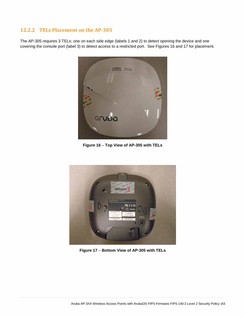
Aruba AP-3XX Wireless Access Points with ArubaOS FIPS Firmware FIPS 140-2 Level 2 Security Policy |43
12.2.2 TELs Placement on the AP-305
The AP-305 requires 3 TELs: one on each side edge (labels 1 and 2) to detect opening the device and one
covering the console port (label 3) to detect access to a restricted port. See Figures 16 and 17 for placement.
Figure 16 – Top View of AP-305 with TELs
Figure 17 – Bottom View of AP-305 with TELs

44| Aruba AP-3XX Wireless Access Points with ArubaOS FIPS Firmware FIPS 140-2 Level 2 Security Policy
12.2.3 TELs Placement on the AP-314
The AP-314 requires 3 TELs: one on each side edge (labels 1 and 2) to detect opening the device and one
covering the console port (label 3) to detect access to a restricted port. See Figures 18 and 19 for placement.
Figure 18 – Top View of AP-314 with TELs
Figure 19 – Bottom View of AP-314 with TELs

Aruba AP-3XX Wireless Access Points with ArubaOS FIPS Firmware FIPS 140-2 Level 2 Security Policy |45
12.2.4 TELs Placement on the AP-315
The AP-315 requires 3 TELs: one on each side edge (labels 1 and 2) to detect opening the device and one
covering the console port (label 3) to detect access to a restricted port. See Figures 20 and 21 for placement.
Figure 20 – Top View of AP-315 with TELs
Figure 21 – Bottom View of AP-315 with TELs

46| Aruba AP-3XX Wireless Access Points with ArubaOS FIPS Firmware FIPS 140-2 Level 2 Security Policy
12.2.5 TELs Placement on the AP-334
The AP-334 requires 3 TELs: one on each side edge (labels 1 and 2) to detect opening the device and one
covering the console port (label 3) to detect access to a restricted port. See Figures 22 and 23 for placement.
Figure 22 – Top View of AP-334 with TELs
Figure 23 – Bottom View of AP-334 with TELs

Aruba AP-3XX Wireless Access Points with ArubaOS FIPS Firmware FIPS 140-2 Level 2 Security Policy |47
12.2.6 TELs Placement on the AP-335
The AP-335 requires 3 TELs: one on each side edge (labels 1 and 2) to detect opening the device and one
covering the console port (label 3) to detect access to a restricted port. See Figures 24 and 25 for placement.
Figure 24 – Top View of AP-335 with TELs
Figure 25 – Bottom View of AP-335 with TELs

48| Aruba AP-3XX Wireless Access Points with ArubaOS FIPS Firmware FIPS 140-2 Level 2 Security Policy
12.2.7. TELs Placement on the AP-365/367
The AP-365 and AP-367 require 3 TELs each: one on each side edge (labels 1 and 2) to detect opening the device
and one covering the console port (label 3) to detect access to a restricted port. See Figures 26 and 27 for placement.
Figure 26 – Top View of AP-365/AP-367 with TELs
Figure 27 – Bottom View of AP-365/AP-367 with TELs

Aruba AP-3XX Wireless Access Points with ArubaOS FIPS Firmware FIPS 140-2 Level 2 Security Policy |49
12.3. Applying TELs
The Crypto Officer should employ TELs as follows:
Before applying a TEL, make sure the target surfaces are clean and dry. Clean with alcohol and let dry.
Do not cut, trim, punch, or otherwise alter the TEL.
Apply the wholly intact TEL firmly and completely to the target surfaces.
Press down firmly across the entire label surface, making several back-and-forth passes to ensure that the label
securely adheres to the device.
Ensure that TEL placement is not defeated by simultaneous removal of multiple modules.
Allow 24 hours for the TEL adhesive seal to completely cure.
Record the position and serial number of each applied TEL in a security log.
To obtain additional or replacement TELS, please call Aruba Networks customer support and request FIPS Kit,
part number 4011570-01 (HPE SKU JY894A).
Once the TELs are applied, the Crypto Officer (CO) should perform initial setup and configuration as described in
the next chapter.
12.4. Inspection/Testing of Physical Security Mechanisms
The Crypto Officer should inspect/test the physical security mechanisms according to the recommended test
frequency.
Table 15 - Inspection/Testing of Physical Security Mechanisms
Physical Security Mechanism Recommended Test Frequency Guidance
Tamper-evident labels (TELs) Once per month Examine for any sign of removal, replacement, tearing, etc..
See images above for locations of TELs.
If any TELS are found to be missing or damaged, contact a system administrator immediately.
Opaque module enclosure Once per month Examine module enclosure for any evidence of new openings or other access to the module internals.
If any indication is found that indicates tampering, contact a system administrator immediately.
50| Aruba AP-3XX Wireless Access Points with ArubaOS FIPS Firmware FIPS 140-2 Level 2 Security Policy
13. Secure Operation
The Aruba AP-304, AP-305, AP-314, AP-315, AP-334, AP-335, AP-365, and AP-367 Wireless Access Points meet
FIPS 140-2 Level 2 requirements. The information below describes how to keep the Wireless Access Point in a
FIPS-Approved mode of operation.
The module can be configured to be in only the following FIPS Approved modes of operation via corresponding
Aruba Mobility Controllers that have been certified to FIPS level 2:
Table 16 - FIPS Approved Modes of Operation
FIPS-Approved Modes of
Operation Description
Remote AP FIPS mode When the module is configured as a Remote AP, it is intended to be deployed in a remote location (relative to the Mobility Controller). The module provides cryptographic processing in the form of IPSec for all traffic to and from the Mobility Controller.
Control Plane Security (CPSec) Protected AP FIPS mode
When the module is configured as a Control Plane Security Protected AP it is intended to be deployed in a local/private location (LAN, WAN, MPLS) relative to the Mobility Controller. The module provides cryptographic processing in the form of IPSec for all Control traffic to and from the Mobility Controller.
Mesh Portal FIPS mode When the module is configured in Mesh Portal mode, it is intended to be connected over a physical wire to the Mobility Controller. These modules serve as the connection point between the Mesh Point and the Mobility Controller. Mesh Portals communicate with the Mobility Controller through IPSec and with Mesh Points via 802.11i session. The Crypto Officer role is the Mobility Controller that authenticates via IKEv1 pre-shared key or RSA/ECDSA certificate authentication method, and Users are the "n" Mesh Points that authenticate via 802.11i pre-shared key.
Mesh Point FIPS mode When the module is configured in Mesh Point mode, it is an AP that establishes an all wireless path to the Mesh portal over 802.11i and an IPSec tunnel via the Mesh Portal to the Controller.
In addition, the module also supports a non-FIPS mode – an un-provisioned AP, which by default does not serve
any wireless clients.
Note: To change configurations from any one mode to any other mode requires the module to be re-provisioned
and rebooted before any new configured mode can be enabled.
The Crypto Officer must ensure that the Wireless Access Point is kept in a FIPS-Approved mode of operation.
Aruba AP-3XX Wireless Access Points with ArubaOS FIPS Firmware FIPS 140-2 Level 2 Security Policy |51
13.1. Crypto Officer Management
The Crypto Officer must ensure that the Wireless Access Point is always operating in a FIPS-Approved mode of
operation. This can be achieved by ensuring the following:
The Crypto Officer must first enable and then provision the AP into a FIPS AP mode of operation before Users are permitted to use the Wireless Access Point (see section 13.5, Enabling FIPS Mode on the Staging Controller).
Only firmware updates signed with SHA-256/RSA 2048 are permitted.
Passwords must be at least eight (8) characters long.
Only FIPS-Approved algorithms can be used for cryptographic services. Please refer to section 8.1, FIPS Approved Algorithms, for the list of Approved algorithms.
The Wireless Access Point logs must be monitored. If a strange activity is found, the Crypto Officer should take the Wireless Access Point offline and investigate.
The Tamper-Evident Labels (TELs) must be regularly examined for signs of tampering. Refer to Table 15 in section 12.4, Inspection/Testing of Physical Security Mechanisms, for the recommended frequency.
When installing expansion or replacement modules for the Aruba AP-304, AP-305, AP-314, AP-315, AP-334, AP-335, AP-365, and AP-367 Wireless Access Points, use only FIPS-Approved modules, replace TELs affected by the change, and record the reason for the change, along with the new TEL locations and serial numbers, in the security log.
All configuration performed through the Mobility Master when configured as a managed device must ensure that only the approved algorithms and services are enabled on the FIPS-enabled Wireless Access Point.
Refer to section 13.6, Non-Approved Mode Configurations for non-Approved configurations in a FIPS-Approved mode.
The user is responsible for zeroizing all CSPs when switching modes.
13.2. User Guidance
Although outside the boundary of the Wireless Access Point, the User should be directed to be careful not to
provide authentication information and session keys to others parties.
13.3. Setup and Configuration
The Aruba AP-304, AP-305, AP-314, AP-315, AP-334, AP-335, AP-365, and AP-367 Wireless Access Points meet
FIPS 140-2 Security Level 2 requirements. The sections below describe how to place and keep the Wireless
Access Point in a FIPS-Approved mode of operation. The Crypto Officer (CO) must ensure that the Wireless
Access Point is kept in a FIPS-Approved mode of operation.
The Wireless Access Point can operate in one of four FIPS-Approved modes: Control Plane Security (CPSec)
Protected AP FIPS mode, Remote AP FIPS mode and the two (2) Mesh modes, Mesh Portal FIPS mode and Mesh
Point FIPS mode (see Table 16 above). By default, the Wireless Access Point operates in the standard non-FIPS
mode.
The Access Point is managed by an Aruba Mobility Controller in FIPS mode, and access to the Mobility Controller’s
administrative interface via a non-networked general purpose computer is required to assist in placing the module
in FIPS mode. The Controller used to provision the AP is referred to as the “staging controller”. The staging
controller must be provisioned with the appropriate firmware image for the module, which has been validated to
FIPS 140-2, prior to initiating AP provisioning. Additionally, if a Mobility Master Appliance is deployed in the
environment, provisioning of the APs can be performed by passing policies down from the Mobility Master to the
Mobility Controller which then provisions the AP.
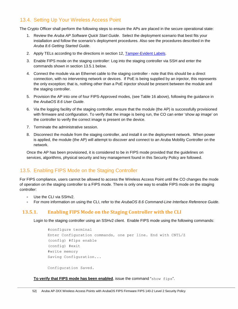
52| Aruba AP-3XX Wireless Access Points with ArubaOS FIPS Firmware FIPS 140-2 Level 2 Security Policy
13.4. Setting Up Your Wireless Access Point
The Crypto Officer shall perform the following steps to ensure the APs are placed in the secure operational state:
1. Review the Aruba AP Software Quick Start Guide. Select the deployment scenario that best fits your
installation and follow the scenario’s deployment procedures. Also see the procedures described in the
Aruba 8.6 Getting Started Guide.
2. Apply TELs according to the directions in section 12, Tamper-Evident Labels.
3. Enable FIPS mode on the staging controller: Log into the staging controller via SSH and enter the
commands shown in section 13.5.1 below.
4. Connect the module via an Ethernet cable to the staging controller - note that this should be a direct
connection, with no intervening network or devices. If PoE is being supplied by an injector, this represents
the only exception; that is, nothing other than a PoE injector should be present between the module and
the staging controller.
5. Provision the AP into one of four FIPS-Approved modes, (see Table 16 above), following the guidance in
the ArubaOS 8.6 User Guide.
6. Via the logging facility of the staging controller, ensure that the module (the AP) is successfully provisioned
with firmware and configuration. To verify that the image is being run, the CO can enter ‘show ap image’ on
the controller to verify the correct image is present on the device.
7. Terminate the administrative session.
8. Disconnect the module from the staging controller, and install it on the deployment network. When power
is applied, the module (the AP) will attempt to discover and connect to an Aruba Mobility Controller on the
network.
Once the AP has been provisioned, it is considered to be in FIPS mode provided that the guidelines on
services, algorithms, physical security and key management found in this Security Policy are followed.
13.5. Enabling FIPS Mode on the Staging Controller
For FIPS compliance, users cannot be allowed to access the Wireless Access Point until the CO changes the mode
of operation on the staging controller to a FIPS mode. There is only one way to enable FIPS mode on the staging
controller:
Use the CLI via SSHv2.
For more information on using the CLI, refer to the ArubaOS 8.6 Command-Line Interface Reference Guide.
13.5.1. Enabling FIPS Mode on the Staging Controller with the CLI
Login to the staging controller using an SSHv2 client. Enable FIPS mode using the following commands:
#configure terminal
Enter Configuration commands, one per line. End with CNTL/Z
(config) #fips enable
(config) #exit
#write memory
Saving Configuration...
Configuration Saved.
To verify that FIPS mode has been enabled, issue the command “show fips”.
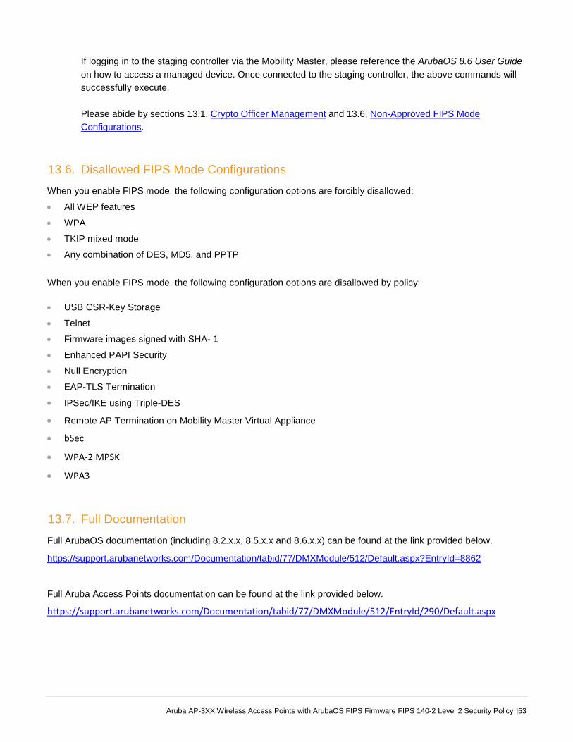
Aruba AP-3XX Wireless Access Points with ArubaOS FIPS Firmware FIPS 140-2 Level 2 Security Policy |53
If logging in to the staging controller via the Mobility Master, please reference the ArubaOS 8.6 User Guide
on how to access a managed device. Once connected to the staging controller, the above commands will
successfully execute.
Please abide by sections 13.1, Crypto Officer Management and 13.6, Non-Approved FIPS Mode
Configurations.
13.6. Disallowed FIPS Mode Configurations
When you enable FIPS mode, the following configuration options are forcibly disallowed:
All WEP features
WPA
TKIP mixed mode
Any combination of DES, MD5, and PPTP
When you enable FIPS mode, the following configuration options are disallowed by policy:
USB CSR-Key Storage
Telnet
Firmware images signed with SHA- 1
Enhanced PAPI Security
Null Encryption
EAP-TLS Termination
IPSec/IKE using Triple-DES
Remote AP Termination on Mobility Master Virtual Appliance
bSec
WPA-2 MPSK
WPA3
13.7. Full Documentation
Full ArubaOS documentation (including 8.2.x.x, 8.5.x.x and 8.6.x.x) can be found at the link provided below.
https://support.arubanetworks.com/Documentation/tabid/77/DMXModule/512/Default.aspx?EntryId=8862
Full Aruba Access Points documentation can be found at the link provided below.
https://support.arubanetworks.com/Documentation/tabid/77/DMXModule/512/EntryId/290/Default.aspx