aruba 802.11ac networkscommunity.arubanetworks.com/aruba/attachments/aruba... ·...
TRANSCRIPT
Aruba 802.11ac Networks
Validated Reference Design
2 | Aruba 802.11ac Networks
Copyright Information
© 2015 ArubaNetworks, Inc. ArubaNetworks trademarks include , ArubaNetworks®, ArubaWireless Networks®, the registered Aruba theMobile Edge Company logo, ArubaMobility ManagementSystem®, Mobile Edge Architecture®, PeopleMove. NetworksMust Follow®, RFProtect®, Green Island®,ClientMatch®, Aruba Central®, ETips™, Virtual Intranet Access™, Aruba Instant™, ArubaOS™, xSec™,ServiceEdge™, Aruba ClearPass AccessManagement System™, AirMesh™, AirWave™, Aruba@Work™, CloudWiFi™, Aruba Cloud™, Adaptive Radio Management™, Secure Air™, Stable Air™, Simple Air™, Mobility-DefinedNetworks™, ArubaMobility-Defined Networks™, Meridian™ and ArubaCare™. All rights reserved. All othertrademarks are the property of their respective owners.
Open Source Code
Certain Aruba products includeOpen Source software code developed by third parties, including software codesubject to theGNU General Public License (GPL), GNU Lesser General Public License (LGPL), or other OpenSource Licenses. Includes software for Litech Systems Design. The IF-MAP client library copyright 2011Infoblox, Inc. All rights reserved. This product includes software developed by Lars Fenneberg et al. TheOpenSource code used can be found at this site:
http://www.arubanetworks.com/open_source
Legal Notice
The use of ArubaNetworks, Inc. switching platforms and software, by all individuals or corporations, toterminate other vendor’s VPN client devices constitutes complete acceptance of liability by that individual orcorporation for this action and indemnifies, in full, ArubaNetworks, Inc. from any and all legal actions thatmight be taken against it with respect to infringement of copyright on behalf of those vendors.
Warranty
This hardware product is protected by an Arubawarranty. For details, see the ArubaNetworks standardwarranty terms and conditions.

Aruba 802.11ac Networks Contents | 3
Contents
Contents 3
Introduction 5
Summary of Recommendations 7
Wired Network Considerations 7
RF Planning 7
WLAN Optimizations 8
802.11ac Features and Benefits 11
Wide RF Channel Bandwidths 11
OFDM Subcarriers 12
More Spatial Streams 13
Spatial Streams 13
UnderstandingMIMO andMU-MIMO 13
Space Time Block Coding, MaximumRatio Combining, and Short Guard Interval 15
Space Time Block Coding 15
Maximal Ratio Combining 15
Short Guard Interval 15
Transmit Beamforming 15
Modulation and Rates 16
Error CorrectionMethods 18
FrameAggregation, A-MPDU, and A-MSDU 18
Power-Save Enhancements 19
Backward Compatibility 20
Protection, Dynamic Bandwidth, and Channelization 20
802.11ac Planning and Deployment Guidelines 23
Wired Network Considerations 24
AP Power Requirements 24
AP Uplink Considerations 25
Access Network Uplink Consideration 25
Jumbo Frames 26
4 | Contents Aruba 802.11ac Networks
VLAN Design 26
Wireless VLAN Design 26
RF Planning 27
APMounting Recommendations 27
CeilingMount Deployment 27
Wall Deployment 27
Site Survey 28
Factors AttenuatingWireless Signals 30
Wi-Fi and Non-Wi-Fi Interference Sources 30
ForwardingMode Recommendations 31
Tunnel Mode 31
Decrypt-Tunnel Mode 32
ChannelWidth Selection 32
Capacity planning 33
WLAN Optimizations 35
Adaptive Radio Management (ARM) 35
Channel and Power Settings 35
ClientMatch 37
ClientMatch Capabilities 37
Band Steering 37
Sticky Client Steering 37
Dynamic Load Balancing 38
Broadcast/Multicast (BC/MC) Optimization 38
AirGroup 39
DynamicMulticast Optimization (DMO) 39
DynamicMulticast Optimization 39
Multicast RateOptimization 40
Traffic Shaping 41
Wi-Fi Multimedia and Quality of Service (QoS) 41
End-to-End QoS 42
Aruba 802.11ac Networks Introduction | 5
Chapter 1Introduction
Wi-Fi has evolved frombeing a nice-to-have service to amission-critical solution in enterprise communications.With the introduction of 802.11ac technology, which provides gigabit speed, many companies aremovingtowards all-wireless offices. Gone are the days where employees used desktops with wired connections anddesk phones. The advancements inWi-Fi technology hasmade theworkplacemobile. Because of mobility,employees can have quick and easy access to data irrespective of their physical location, which improves userproductivity and reduces IT cost. It is common for an employee to carry two ormore devices – for example,smartphone, tablet, and laptop. Most of these newer devices do not comewith Ethernet ports and henceWi-Fiis their primary mode of network access.
Mobile technology has reached the next frontier – video. Whether it is delivering buffered video like YouTubeto smartphones or streaming HDTV video around the office or home, video has become a significant driver ofnetwork traffic. This ismainly because video requires twicemore bandwidth than other IP services and is acontinuous traffic stream as compared to transactional and bursty traffic like email orWeb browsing. Supportfor voice and video traffic becomes important for an all-wireless workplace that uses Unified Communicationsand Collaborations (UCC) applications likeMicrosoft Lync for webinars and video conferencing. The recentmove to cloud-based services by companies also adds stress to today's network bandwidth due to the shift tohaving documents downloaded on demand tomobile devices rather than being stored locally. Ratified as astandard by IEEE in December 2013, 802.11ac is the latest enhancement in the 802.11 standards family forimproving the network performance.
The purpose of this guide is to explain the enhancements in 802.11ac standard and provide guidance towardsmigrating to 802.11ac with respect to network design, deployment, and configuration best practices forcampus environments like offices, university campus, and dorm environments.
This guide covers the following topics in detail:
l Summary of Recommendations
l 802.11ac Features and Benefits
l 802.11ac Planning and Deployment Guidelines
l Best Practice Recommendations for Deploying 802.11acWLANs
This guide is intended for thosewho arewilling to learn about the 802.11ac standards and understand thebest practices in deploying a high-performing 802.11acWLAN network by using wireless LAN controllers andAccess Points (APs) fromArubaNetworks, Inc.

Aruba 802.11ac Networks Summary of Recommendations | 7
Chapter 2Summary of Recommendations
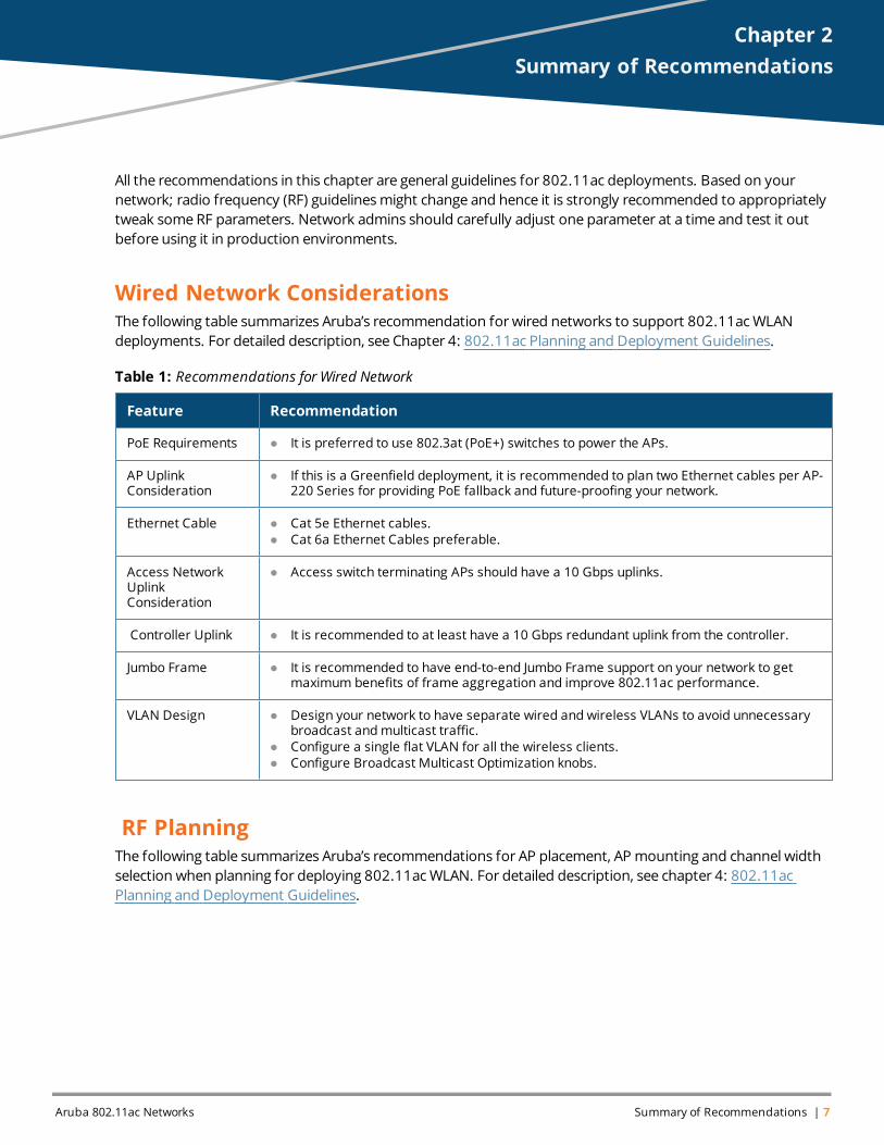
All the recommendations in this chapter are general guidelines for 802.11ac deployments. Based on yournetwork; radio frequency (RF) guidelinesmight change and hence it is strongly recommended to appropriatelytweak someRF parameters. Network admins should carefully adjust one parameter at a time and test it outbefore using it in production environments.
Wired Network ConsiderationsThe following table summarizes Aruba’s recommendation for wired networks to support 802.11acWLANdeployments. For detailed description, see Chapter 4: 802.11ac Planning and Deployment Guidelines.
Feature Recommendation
PoE Requirements l It is preferred to use 802.3at (PoE+) switches to power the APs.
AP UplinkConsideration
l If this is a Greenfield deployment, it is recommended to plan two Ethernet cables per AP-220 Series for providing PoE fallback and future-proofing your network.
Ethernet Cable l Cat 5e Ethernet cables.l Cat 6a Ethernet Cables preferable.
Access NetworkUplinkConsideration
l Access switch terminating APs should have a 10 Gbps uplinks.
Controller Uplink l It is recommended to at least have a 10 Gbps redundant uplink from the controller.
Jumbo Frame l It is recommended to have end-to-end Jumbo Frame support on your network to getmaximum benefits of frame aggregation and improve 802.11ac performance.
VLAN Design l Design your network to have separate wired and wireless VLANs to avoid unnecessarybroadcast andmulticast traffic.
l Configure a single flat VLAN for all the wireless clients.l Configure Broadcast Multicast Optimization knobs.
Table 1: Recommendations for Wired Network
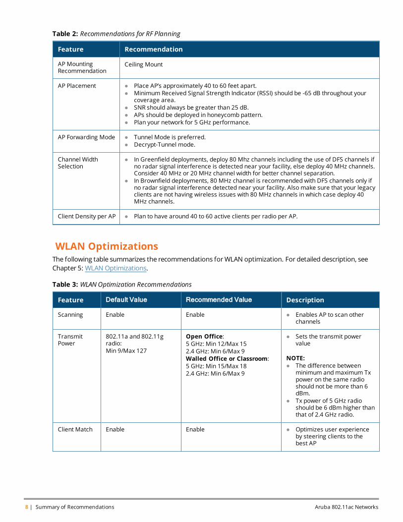
RF PlanningThe following table summarizes Aruba’s recommendations for AP placement, AP mounting and channel widthselection when planning for deploying 802.11acWLAN. For detailed description, see chapter 4: 802.11acPlanning and Deployment Guidelines.
8 | Summary of Recommendations Aruba 802.11ac Networks
Feature Recommendation
AP MountingRecommendation
Ceiling Mount
AP Placement l Place AP’s approximately 40 to 60 feet apart.l Minimum Received Signal Strength Indicator (RSSI) should be -65 dB throughout your
coverage area.l SNR should always be greater than 25 dB.l APs should be deployed in honeycomb pattern.l Plan your network for 5 GHz performance.
AP Forwarding Mode l Tunnel Mode is preferred.l Decrypt-Tunnel mode.
Channel WidthSelection
l In Greenfield deployments, deploy 80 Mhz channels including the use of DFS channels ifno radar signal interference is detected near your facility, else deploy 40 MHz channels.Consider 40 MHz or 20 MHz channel width for better channel separation.
l In Brownfield deployments, 80 MHz channel is recommended with DFS channels only ifno radar signal interference detected near your facility. Also make sure that your legacyclients are not having wireless issues with 80 MHz channels in which case deploy 40MHz channels.
Client Density per AP l Plan to have around 40 to 60 active clients per radio per AP.
Table 2: Recommendations for RF Planning
WLAN OptimizationsThe following table summarizes the recommendations forWLAN optimization. For detailed description, seeChapter 5: WLAN Optimizations.
Feature Default Value Recommended Value Description
Scanning Enable Enable l Enables AP to scan otherchannels
TransmitPower
802.11a and 802.11gradio:Min 9/Max 127
Open Office:5 GHz: Min 12/Max 152.4 GHz: Min 6/Max 9Walled Office or Classroom:5 GHz: Min 15/Max 182.4 GHz: Min 6/Max 9
l Sets the transmit powervalue
NOTE:l The difference between
minimum andmaximum Txpower on the same radioshould not be more than 6dBm.
l Tx power of 5 GHz radioshould be 6 dBm higher thanthat of 2.4 GHz radio.
Client Match Enable Enable l Optimizes user experienceby steering clients to thebest AP
Table 3: WLAN Optimization Recommendations
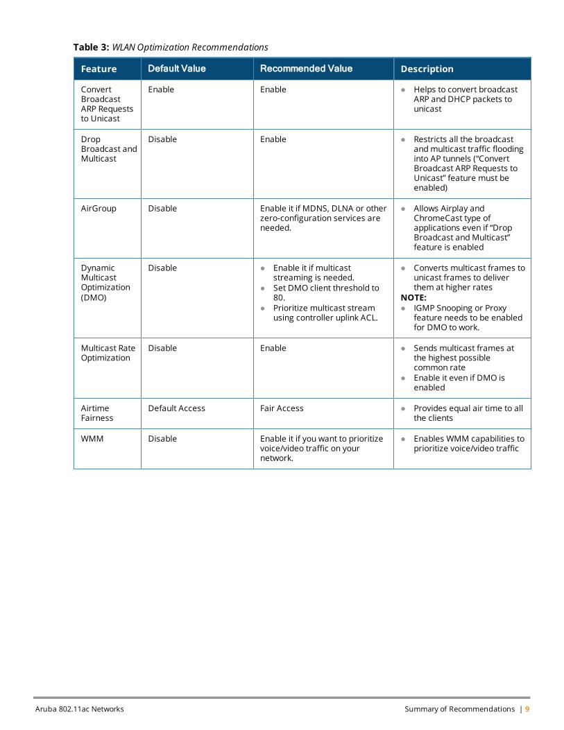
Feature Default Value Recommended Value Description
ConvertBroadcastARP Requeststo Unicast
Enable Enable l Helps to convert broadcastARP and DHCP packets tounicast
DropBroadcast andMulticast
Disable Enable l Restricts all the broadcastandmulticast traffic floodinginto AP tunnels (“ConvertBroadcast ARP Requests toUnicast” feature must beenabled)
AirGroup Disable Enable it if MDNS, DLNA or otherzero-configuration services areneeded.
l Allows Airplay andChromeCast type ofapplications even if “DropBroadcast andMulticast”feature is enabled
DynamicMulticastOptimization(DMO)
Disable l Enable it if multicaststreaming is needed.
l Set DMO client threshold to80.
l Prioritize multicast streamusing controller uplink ACL.
l Converts multicast frames tounicast frames to deliverthem at higher rates
NOTE:l IGMP Snooping or Proxy
feature needs to be enabledfor DMO to work.
Multicast RateOptimization
Disable Enable l Sends multicast frames atthe highest possiblecommon rate
l Enable it even if DMO isenabled
AirtimeFairness
Default Access Fair Access l Provides equal air time to allthe clients
WMM Disable Enable it if you want to prioritizevoice/video traffic on yournetwork.
l Enables WMM capabilities toprioritize voice/video traffic
Table 3: WLAN Optimization Recommendations
Aruba 802.11ac Networks Summary of Recommendations | 9

Aruba 802.11ac Networks 802.11ac Features and Benefits | 11
Chapter 3802.11ac Features and Benefits
The following section outlines the enhancements that were introduced in 802.11ac standard. 802.11ac is thelatest amendment to the 802.11 standard and it increases speed close to threefold compared to 802.11nstandard to provide an Ethernet-like user experience. Some of the key enhancements included in 802.11acstandard are:
l Wide RF Channels
l More Spatial Streams
l MU-MIMO
l Transmit Beamforming
l 256 QAMModulation
l FrameAggregation, A-MPDU, and A-MSDU
l Protection, Dynamic Bandwidth, and Channelization
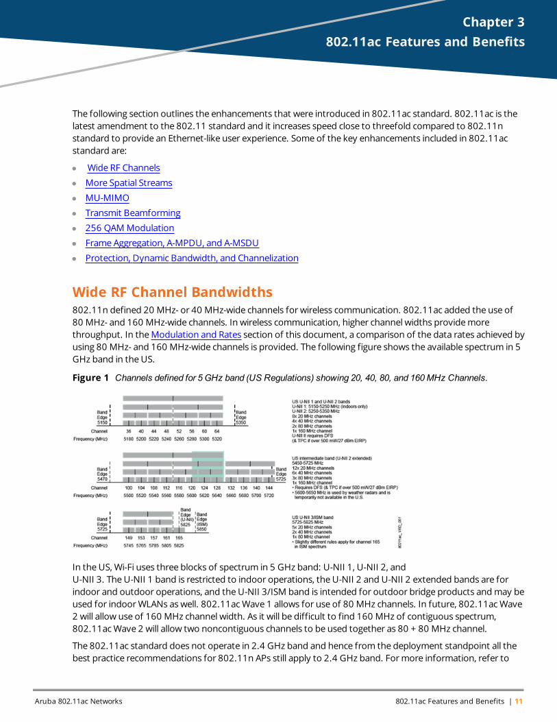
Wide RF Channel Bandwidths802.11n defined 20 MHz- or 40 MHz-wide channels for wireless communication. 802.11ac added the use of80 MHz- and 160 MHz-wide channels. In wireless communication, higher channel widths providemorethroughput. In theModulation and Rates section of this document, a comparison of the data rates achieved byusing 80 MHz- and 160 MHz-wide channels is provided. The following figure shows the available spectrum in 5GHz band in theUS.
Figure 1 Channels defined for 5 GHz band (US Regulations) showing 20, 40, 80, and 160MHz Channels.
In the US, Wi-Fi uses three blocks of spectrum in 5 GHz band: U-NII 1, U-NII 2, andU-NII 3. TheU-NII 1 band is restricted to indoor operations, the U-NII 2 and U-NII 2 extended bands are forindoor and outdoor operations, and theU-NII 3/ISM band is intended for outdoor bridge products andmay beused for indoorWLANs as well. 802.11acWave 1 allows for use of 80 MHz channels. In future, 802.11acWave2 will allow use of 160 MHz channel width. As it will be difficult to find 160 MHz of contiguous spectrum,802.11acWave 2 will allow two noncontiguous channels to be used together as 80 + 80 MHz channel.
The 802.11ac standard does not operate in 2.4 GHz band and hence from the deployment standpoint all thebest practice recommendations for 802.11n APs still apply to 2.4 GHz band. Formore information, refer to
12 | 802.11ac Features and Benefits Aruba 802.11ac Networks
"Aruba 802.11n Networks Validated ReferenceDesign” document availableat:http://www.arubanetworks.com/vrd/80211nNetworksVRD/wwhelp/wwhimpl/js/html/wwhelp.htm
Aruba recommends that customers do not use 40 MHz channels in the2.4 GHz band due to the lack of available bandwidth and high chance of interference with legacy 802.11b/g networks.While it is possible to enable these channels, doing so will result in fewer overall channels and a decrease inthroughput.
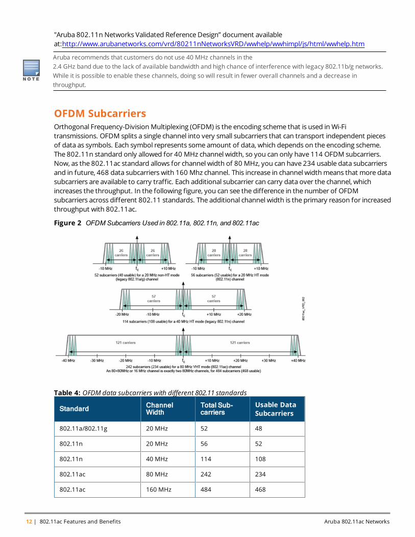
OFDM SubcarriersOrthogonal Frequency-DivisionMultiplexing (OFDM) is the encoding scheme that is used inWi-Fitransmissions. OFDM splits a single channel into very small subcarriers that can transport independent piecesof data as symbols. Each symbol represents some amount of data, which depends on the encoding scheme.The 802.11n standard only allowed for 40 MHz channel width, so you can only have 114 OFDM subcarriers.Now, as the 802.11ac standard allows for channel width of 80 MHz, you can have 234 usable data subcarriersand in future, 468 data subcarriers with 160 Mhz channel. This increase in channel widthmeans that more datasubcarriers are available to carry traffic. Each additional subcarrier can carry data over the channel, whichincreases the throughput. In the following figure, you can see the difference in the number of OFDMsubcarriers across different 802.11 standards. The additional channel width is the primary reason for increasedthroughput with 802.11ac.
Figure 2 OFDM Subcarriers Used in 802.11a, 802.11n, and 802.11ac
Standard ChannelWidth
Total Sub-carriers
Usable DataSubcarriers
802.11a/802.11g 20 MHz 52 48
802.11n 20 MHz 56 52
802.11n 40 MHz 114 108
802.11ac 80 MHz 242 234
802.11ac 160 MHz 484 468
Table 4: OFDM data subcarriers with different 802.11 standards
Some of the subcarriers that do not carry data are called pilot carriers. These are used for the measurement ofchannel conditions like phase shift for each subcarrier and can also be used for synchronization to avoid intersymbolinterference. This accounts for the difference in the number of total subcarriers and usable data subcarriers.
More Spatial Streams
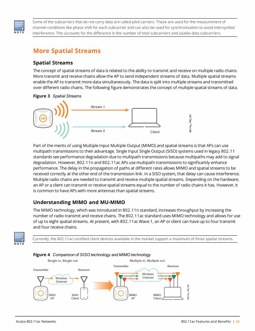
Spatial StreamsThe concept of spatial streams of data is related to the ability to transmit and receive onmultiple radio chains.More transmit and receive chains allow the AP to send independent streams of data. Multiple spatial streamsenable the AP to transmit more data simultaneously. The data is split into multiple streams and transmittedover different radio chains. The following figure demonstrates the concept of multiple spatial streams of data.
Figure 3 Spatial Streams
Part of themerits of usingMultiple Input Multiple Output (MIMO) and spatial streams is that APs can usemultipath transmissions to their advantage. Single Input Single Output (SISO) systems used in legacy 802.11standards see performance degradation due to multipath transmissions becausemultipathsmay add to signaldegradation. However, 802.11n and 802.11ac APs usemultipath transmissions to significantly enhanceperformance. The delay in the propagation of paths at different rates allowsMIMO and spatial streams to bereceived correctly at the other end of the transmission link. In a SISO system, that delay can cause interference.Multiple radio chains are needed to transmit and receivemultiple spatial streams. Depending on the hardware,an AP or a client can transmit or receive spatial streams equal to the number of radio chains it has. However, itis common to have APs withmore antennas than spatial streams.
Understanding MIMO and MU-MIMOTheMIMO technology, which was introduced in 802.11n standard, increases throughput by increasing thenumber of radio transmit and receive chains. The 802.11ac standard usesMIMO technology and allows for useof up to eight spatial streams. At present, with 802.11acWave 1, an AP or client can have up to four transmitand four receive chains.
Currently, the 802.11ac-certified client devices available in the market support a maximum of three spatial streams.
Figure 4 Comparison of SISO technology andMIMO technology
Aruba 802.11ac Networks 802.11ac Features and Benefits | 13
14 | 802.11ac Features and Benefits Aruba 802.11ac Networks
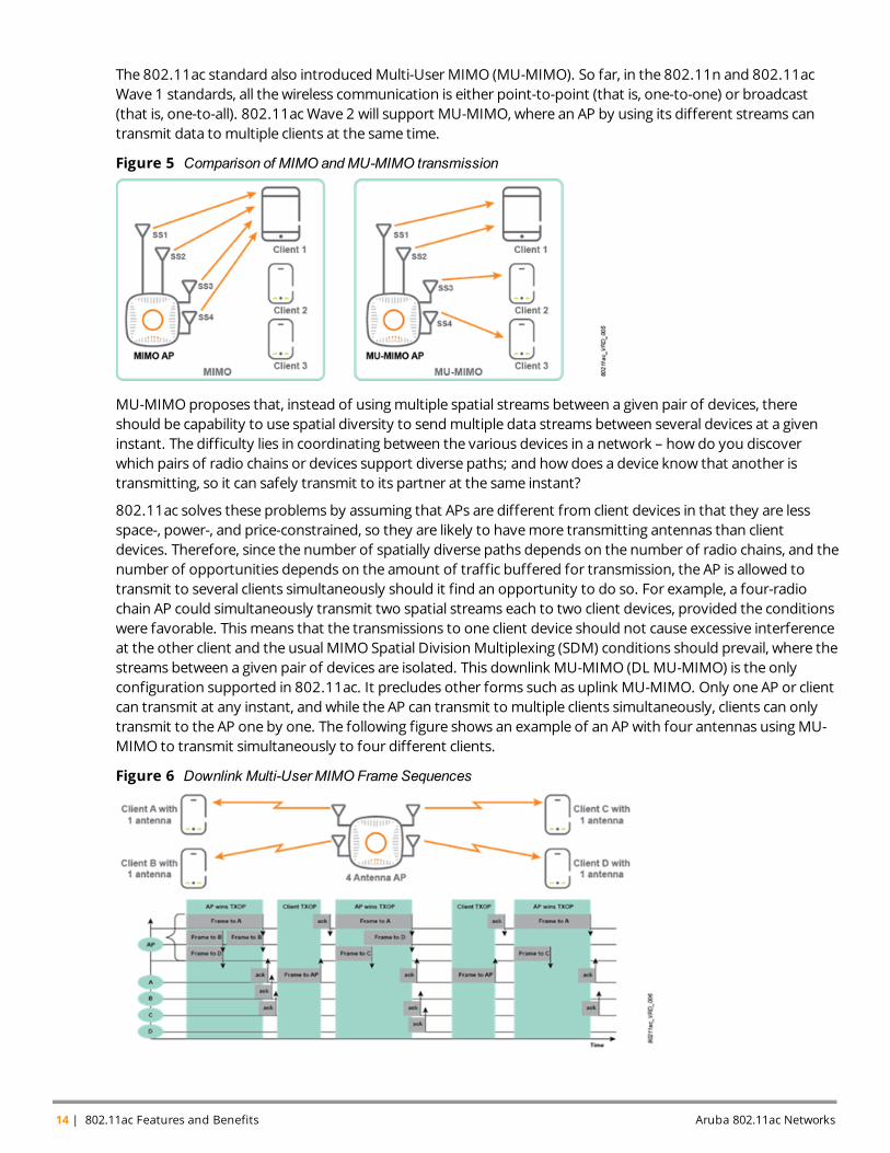
The 802.11ac standard also introducedMulti-UserMIMO (MU-MIMO). So far, in the 802.11n and 802.11acWave 1 standards, all thewireless communication is either point-to-point (that is, one-to-one) or broadcast(that is, one-to-all). 802.11acWave 2 will support MU-MIMO, where an AP by using its different streams cantransmit data to multiple clients at the same time.
Figure 5 Comparison of MIMO andMU-MIMO transmission
MU-MIMOproposes that, instead of usingmultiple spatial streams between a given pair of devices, thereshould be capability to use spatial diversity to sendmultiple data streams between several devices at a giveninstant. The difficulty lies in coordinating between the various devices in a network – how do you discoverwhich pairs of radio chains or devices support diverse paths; and how does a device know that another istransmitting, so it can safely transmit to its partner at the same instant?
802.11ac solves these problems by assuming that APs are different from client devices in that they are lessspace-, power-, and price-constrained, so they are likely to havemore transmitting antennas than clientdevices. Therefore, since the number of spatially diverse paths depends on the number of radio chains, and thenumber of opportunities depends on the amount of traffic buffered for transmission, the AP is allowed totransmit to several clients simultaneously should it find an opportunity to do so. For example, a four-radiochain AP could simultaneously transmit two spatial streams each to two client devices, provided the conditionswere favorable. Thismeans that the transmissions to one client device should not cause excessive interferenceat the other client and the usual MIMO Spatial DivisionMultiplexing (SDM) conditions should prevail, where thestreams between a given pair of devices are isolated. This downlink MU-MIMO (DL MU-MIMO) is the onlyconfiguration supported in 802.11ac. It precludes other forms such as uplink MU-MIMO. Only one AP or clientcan transmit at any instant, and while the AP can transmit to multiple clients simultaneously, clients can onlytransmit to the AP one by one. The following figure shows an example of an AP with four antennas usingMU-MIMO to transmit simultaneously to four different clients.
Figure 6 Downlink Multi-User MIMO Frame Sequences
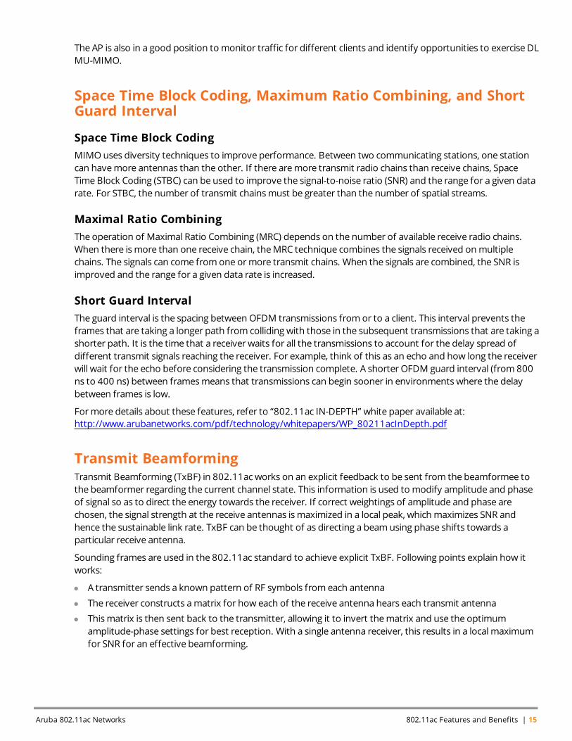
The AP is also in a good position to monitor traffic for different clients and identify opportunities to exercise DLMU-MIMO.
Space Time Block Coding, Maximum Ratio Combining, and ShortGuard Interval
Space Time Block CodingMIMOuses diversity techniques to improve performance. Between two communicating stations, one stationcan havemore antennas than the other. If there aremore transmit radio chains than receive chains, SpaceTime Block Coding (STBC) can be used to improve the signal-to-noise ratio (SNR) and the range for a given datarate. For STBC, the number of transmit chainsmust be greater than the number of spatial streams.
Maximal Ratio CombiningThe operation of Maximal Ratio Combining (MRC) depends on the number of available receive radio chains.When there ismore than one receive chain, theMRC technique combines the signals received onmultiplechains. The signals can come fromone ormore transmit chains. When the signals are combined, the SNR isimproved and the range for a given data rate is increased.
Short Guard IntervalThe guard interval is the spacing between OFDM transmissions fromor to a client. This interval prevents theframes that are taking a longer path from colliding with those in the subsequent transmissions that are taking ashorter path. It is the time that a receiver waits for all the transmissions to account for the delay spread ofdifferent transmit signals reaching the receiver. For example, think of this as an echo and how long the receiverwill wait for the echo before considering the transmission complete. A shorter OFDM guard interval (from 800ns to 400 ns) between framesmeans that transmissions can begin sooner in environments where the delaybetween frames is low.
Formore details about these features, refer to “802.11ac IN-DEPTH” white paper available at:http://www.arubanetworks.com/pdf/technology/whitepapers/WP_80211acInDepth.pdf
Transmit BeamformingTransmit Beamforming (TxBF) in 802.11ac works on an explicit feedback to be sent from the beamformee tothe beamformer regarding the current channel state. This information is used to modify amplitude and phaseof signal so as to direct the energy towards the receiver. If correct weightings of amplitude and phase arechosen, the signal strength at the receive antennas ismaximized in a local peak, whichmaximizes SNR andhence the sustainable link rate. TxBF can be thought of as directing a beamusing phase shifts towards aparticular receive antenna.
Sounding frames are used in the 802.11ac standard to achieve explicit TxBF. Following points explain how itworks:
l A transmitter sends a known pattern of RF symbols from each antenna
l The receiver constructs amatrix for how each of the receive antenna hears each transmit antenna
l Thismatrix is then sent back to the transmitter, allowing it to invert thematrix and use the optimumamplitude-phase settings for best reception. With a single antenna receiver, this results in a local maximumfor SNR for an effective beamforming.
Aruba 802.11ac Networks 802.11ac Features and Benefits | 15
16 | 802.11ac Features and Benefits Aruba 802.11ac Networks
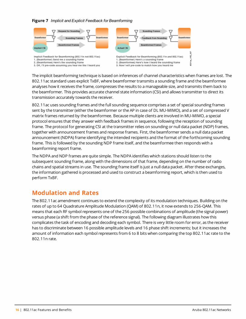
Figure 7 Implicit and Explicit Feedback for Beamforming
The implicit beamforming technique is based on inferences of channel characteristics when frames are lost. The802.11ac standard uses explicit TxBF, where beamformer transmits a sounding frame and the beamformeeanalyses how it receives the frame, compresses the results to amanageable size, and transmits themback tothe beamformer. This provides accurate channel state information (CSI) and allows transmitter to direct itstransmission accurately towards the receiver.
802.11ac uses sounding frames and the full sounding sequence comprises a set of special sounding framessent by the transmitter (either the beamformer or the AP in case of DL MU-MIMO), and a set of compressed Vmatrix frames returned by the beamformee. Becausemultiple clients are involved in MU-MIMO, a specialprotocol ensures that they answer with feedback frames in sequence, following the reception of soundingframe. The protocol for generating CSI at the transmitter relies on sounding or null data packet (NDP) frames,together with announcement frames and response frames. First, the beamformer sends a null data packetannouncement (NDPA) frame identifying the intended recipients and the format of the forthcoming soundingframe. This is followed by the sounding NDP frame itself, and the beamformee then responds with abeamforming report frame.
TheNDPA and NDP frames are quite simple. TheNDPA identifies which stations should listen to thesubsequent sounding frame, along with the dimensions of that frame, depending on the number of radiochains and spatial streams in use. The sounding frame itself is just a null data packet. After these exchanges,the information gathered is processed and used to construct a beamforming report, which is then used toperform TxBF.
Modulation and RatesThe 802.11ac amendment continues to extend the complexity of itsmodulation techniques. Building on therates of up to 64 Quadrature AmplitudeModulation (QAM) of 802.11n, it now extends to 256-QAM. Thismeans that each RF symbol represents one of the 256 possible combinations of amplitude (the signal power)versus phase (a shift from the phase of the reference signal). The following diagram illustrates how thiscomplicates the task of encoding and decoding each symbol. There is very little room for error, as the receiverhas to discriminate between 16 possible amplitude levels and 16 phase shift increments; but it increases theamount of information each symbol represents from 6 to 8 bits when comparing the top 802.11ac rate to the802.11n rate.
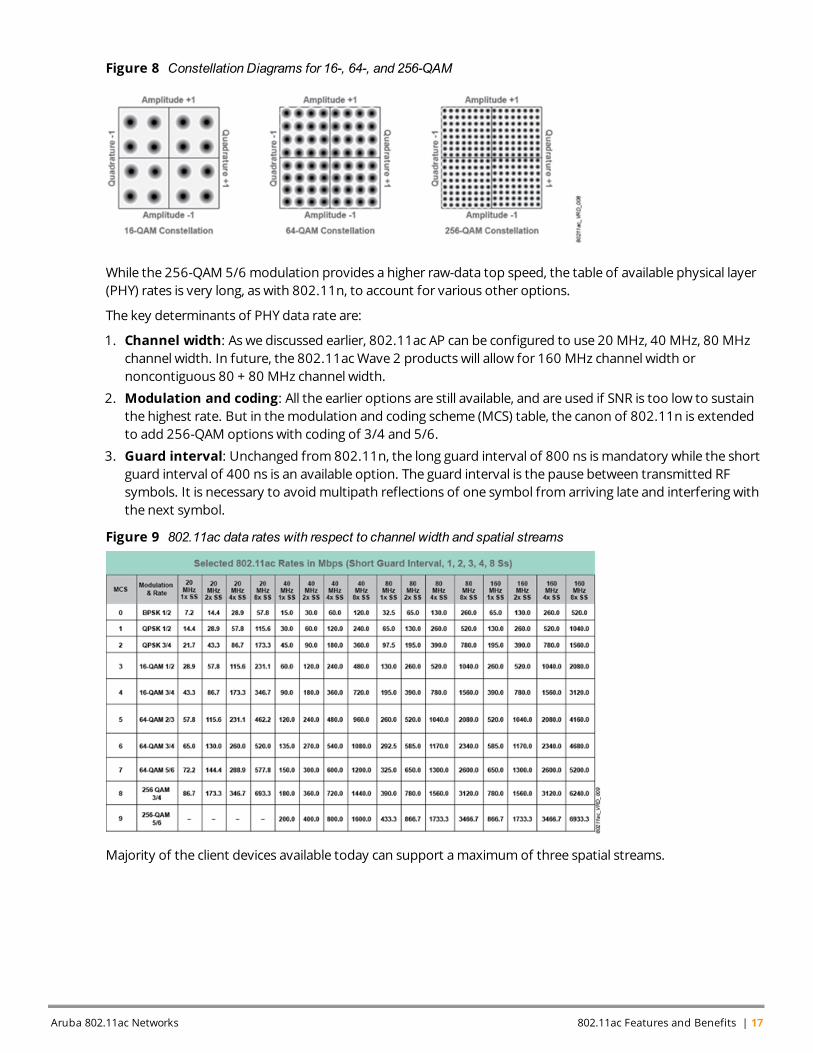
Figure 8 Constellation Diagrams for 16-, 64-, and 256-QAM
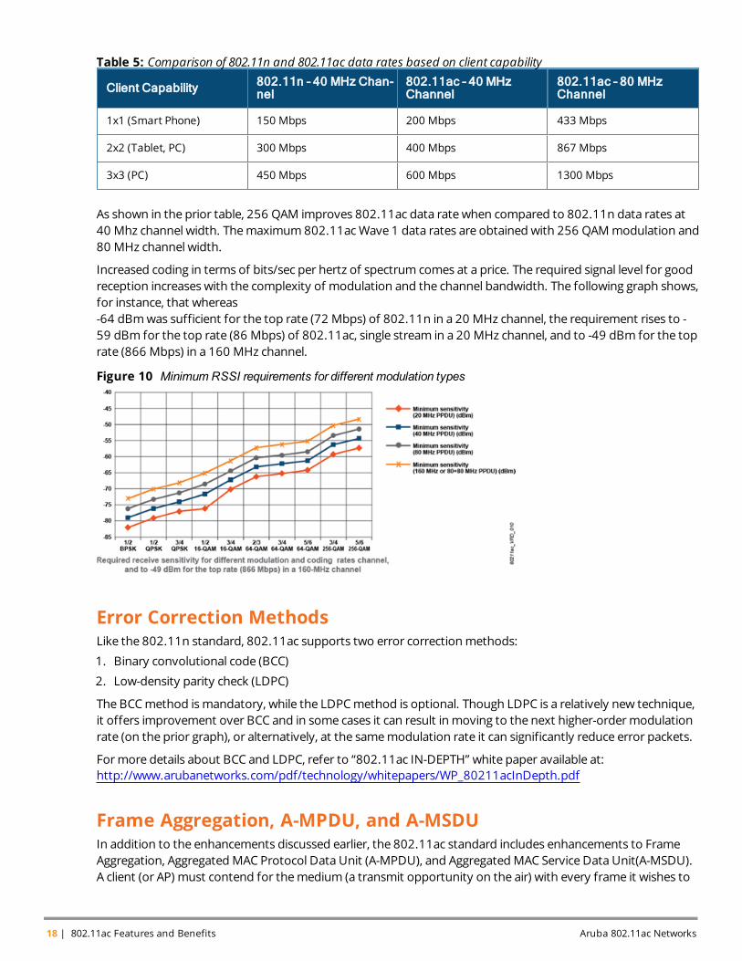
While the 256-QAM 5/6 modulation provides a higher raw-data top speed, the table of available physical layer(PHY) rates is very long, as with 802.11n, to account for various other options.
The key determinants of PHY data rate are:
1. Channel width: As we discussed earlier, 802.11ac AP can be configured to use 20 MHz, 40 MHz, 80 MHzchannel width. In future, the 802.11acWave 2 products will allow for 160 MHz channel width ornoncontiguous 80 + 80 MHz channel width.
2. Modulation and coding: All the earlier options are still available, and are used if SNR is too low to sustainthe highest rate. But in themodulation and coding scheme (MCS) table, the canon of 802.11n is extendedto add 256-QAM options with coding of 3/4 and 5/6.
3. Guard interval: Unchanged from 802.11n, the long guard interval of 800 ns ismandatory while the shortguard interval of 400 ns is an available option. The guard interval is the pause between transmitted RFsymbols. It is necessary to avoidmultipath reflections of one symbol from arriving late and interfering withthe next symbol.
Figure 9 802.11ac data rates with respect to channel width and spatial streams
Majority of the client devices available today can support amaximumof three spatial streams.
Aruba 802.11ac Networks 802.11ac Features and Benefits | 17
18 | 802.11ac Features and Benefits Aruba 802.11ac Networks
Client Capability 802.11n – 40 MHz Chan-nel
802.11ac – 40 MHzChannel
802.11ac – 80 MHzChannel
1x1 (Smart Phone) 150 Mbps 200 Mbps 433 Mbps
2x2 (Tablet, PC) 300 Mbps 400 Mbps 867 Mbps
3x3 (PC) 450 Mbps 600 Mbps 1300 Mbps
Table 5: Comparison of 802.11n and 802.11ac data rates based on client capability
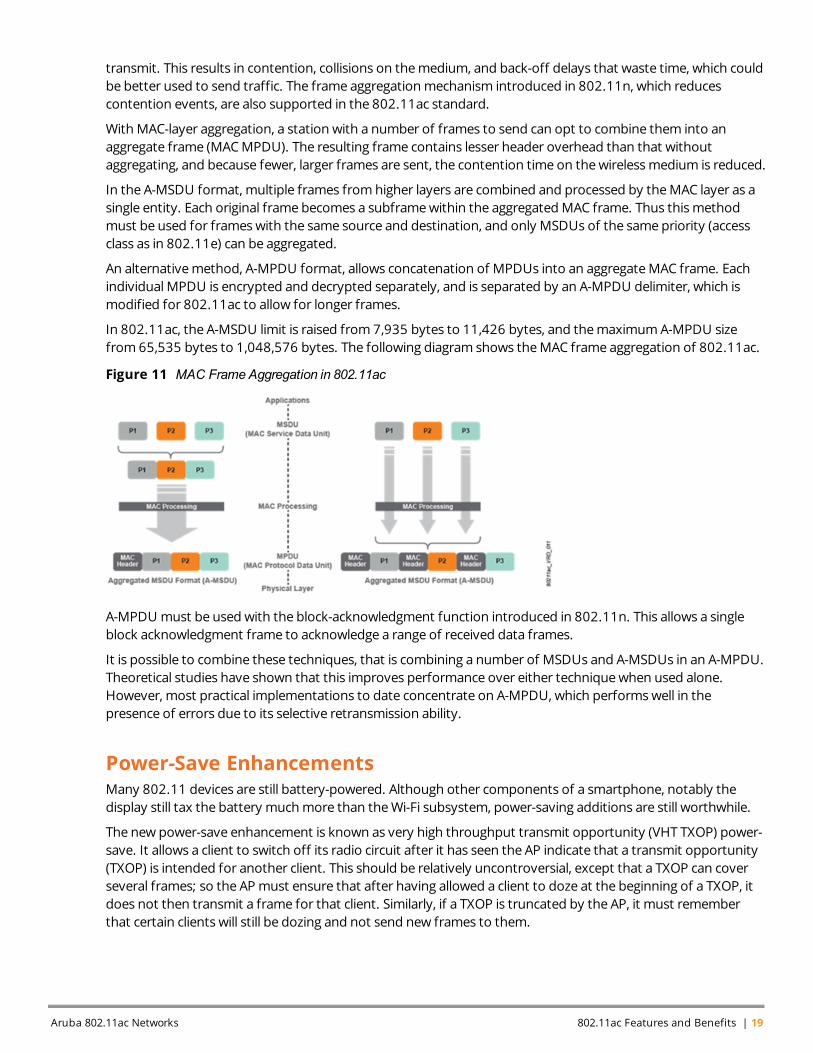
As shown in the prior table, 256 QAM improves 802.11ac data ratewhen compared to 802.11n data rates at40 Mhz channel width. Themaximum802.11acWave 1 data rates are obtained with 256 QAMmodulation and80 MHz channel width.
Increased coding in terms of bits/sec per hertz of spectrum comes at a price. The required signal level for goodreception increases with the complexity of modulation and the channel bandwidth. The following graph shows,for instance, that whereas-64 dBmwas sufficient for the top rate (72 Mbps) of 802.11n in a 20 MHz channel, the requirement rises to -59 dBm for the top rate (86 Mbps) of 802.11ac, single stream in a 20 MHz channel, and to -49 dBm for the toprate (866 Mbps) in a 160 MHz channel.
Figure 10 Minimum RSSI requirements for different modulation types
Error Correction MethodsLike the 802.11n standard, 802.11ac supports two error correctionmethods:
1. Binary convolutional code (BCC)
2. Low-density parity check (LDPC)
The BCCmethod ismandatory, while the LDPCmethod is optional. Though LDPC is a relatively new technique,it offers improvement over BCC and in some cases it can result in moving to the next higher-ordermodulationrate (on the prior graph), or alternatively, at the samemodulation rate it can significantly reduce error packets.
Formore details about BCC and LDPC, refer to “802.11ac IN-DEPTH” white paper available at:http://www.arubanetworks.com/pdf/technology/whitepapers/WP_80211acInDepth.pdf
Frame Aggregation, A-MPDU, and A-MSDUIn addition to the enhancements discussed earlier, the 802.11ac standard includes enhancements to FrameAggregation, AggregatedMAC Protocol Data Unit (A-MPDU), and AggregatedMAC Service Data Unit(A-MSDU).A client (or AP) must contend for themedium (a transmit opportunity on the air) with every frame it wishes to
transmit. This results in contention, collisions on themedium, and back-off delays that waste time, which couldbe better used to send traffic. The frame aggregationmechanism introduced in 802.11n, which reducescontention events, are also supported in the 802.11ac standard.
With MAC-layer aggregation, a station with a number of frames to send can opt to combine them into anaggregate frame (MACMPDU). The resulting frame contains lesser header overhead than that withoutaggregating, and because fewer, larger frames are sent, the contention time on thewirelessmedium is reduced.
In the A-MSDU format, multiple frames fromhigher layers are combined and processed by theMAC layer as asingle entity. Each original frame becomes a subframewithin the aggregatedMAC frame. Thus thismethodmust be used for frameswith the same source and destination, and only MSDUs of the same priority (accessclass as in 802.11e) can be aggregated.
An alternativemethod, A-MPDU format, allows concatenation of MPDUs into an aggregateMAC frame. Eachindividual MPDU is encrypted and decrypted separately, and is separated by an A-MPDU delimiter, which ismodified for 802.11ac to allow for longer frames.
In 802.11ac, the A-MSDU limit is raised from 7,935 bytes to 11,426 bytes, and themaximumA-MPDU sizefrom 65,535 bytes to 1,048,576 bytes. The following diagram shows theMAC frame aggregation of 802.11ac.
Figure 11 MAC Frame Aggregation in 802.11ac
A-MPDU must be used with the block-acknowledgment function introduced in 802.11n. This allows a singleblock acknowledgment frame to acknowledge a range of received data frames.
It is possible to combine these techniques, that is combining a number of MSDUs and A-MSDUs in an A-MPDU.Theoretical studies have shown that this improves performance over either techniquewhen used alone.However, most practical implementations to date concentrate on A-MPDU, which performswell in thepresence of errors due to its selective retransmission ability.
Power-Save EnhancementsMany 802.11 devices are still battery-powered. Although other components of a smartphone, notably thedisplay still tax the battery muchmore than theWi-Fi subsystem, power-saving additions are still worthwhile.
The new power-save enhancement is known as very high throughput transmit opportunity (VHT TXOP) power-save. It allows a client to switch off its radio circuit after it has seen the AP indicate that a transmit opportunity(TXOP) is intended for another client. This should be relatively uncontroversial, except that a TXOP can coverseveral frames; so the APmust ensure that after having allowed a client to doze at the beginning of a TXOP, itdoes not then transmit a frame for that client. Similarly, if a TXOP is truncated by the AP, it must rememberthat certain clients will still be dozing and not send new frames to them.
Aruba 802.11ac Networks 802.11ac Features and Benefits | 19
20 | 802.11ac Features and Benefits Aruba 802.11ac Networks
To allow clients to quickly identify if a frame is addressed to them, a new field called partial association ID(partial AID) or Group ID forMU-MIMO is added to the preamble. If the partial AID field is not its own address,the client can doze for the remainder of the TXOP.
One reason to introduce VHT TXOP power-save is that the frames are getting longer. 802.11ac has extendedframe lengths and now allows for frames approaching 8 KB in length, and aggregated frames (A-MPDU) of 1MB length.
Some of this is accounted by the increased rates, so time on themediumwill not be extended pro-rata. Butvideo and large file transfers, two of themore important use cases, drive large number of long frames (possiblyaggregated as A-MSDU or A-MPDU frames at theWi-Fi layer); so it may well beworthwhile switching off a radiowhile large numbers of frames are being delivered to other clients.
The othermajor power-saving feature of 802.11ac is its high data rates. Power consumption in 802.11 isheavily dependent on the time spent transmitting the data. The higher the rate, the shorter the transmissionburst. The time spent receiving frames is also reduced by high rates, but not so significantly.
Backward CompatibilityBecause 802.11ac includes new, higher-speed techniques, its transmissions are by definition not decodable byolder 802.11 equipment. But it is important that an 802.11ac AP, adjacent to older APs, is a good neighbor.802.11ac has a number of features for co-existence, but themain one is the extension of an 802.11ntechnique: Amultipart RF header that uses 802.11a and 802.11nmodulation. Non-802.11ac equipment canread these headers and identify that the channel will be occupied for a given time, and therefore can avoidtransmitting simultaneously with the very high throughput frame. So 802.11ac is backward compatible withlegacy 802.11 standards and can be deployed inmixed environment with legacy APs.
Protection, Dynamic Bandwidth, and ChannelizationWhen an 80-MHz 802.11ac network operates in the neighborhood of an older AP, or a network that is onlyusing a 20 MHz or 40 MHz channel, it must avoid transmitting simultaneously with a station in the neighboringnetwork. The question here is as to how this can be achieved without permanently reducing its channelbandwidth.
The solution lies in answering these three questions:
1. How can a station (AP or client) that wants to operate at 80 MHz, warn older stations to stay off the airwhile it is transmitting in 802.11acmode, which they cannot decode?
2. Howwill the 802.11ac station know that the full channel is clear of other stations’ transmissions?
3. Finally, how can bandwidth usage be optimized if, for instance, an older station is transmitting in just 20MHz of the 80-MHz 802.11ac channel?
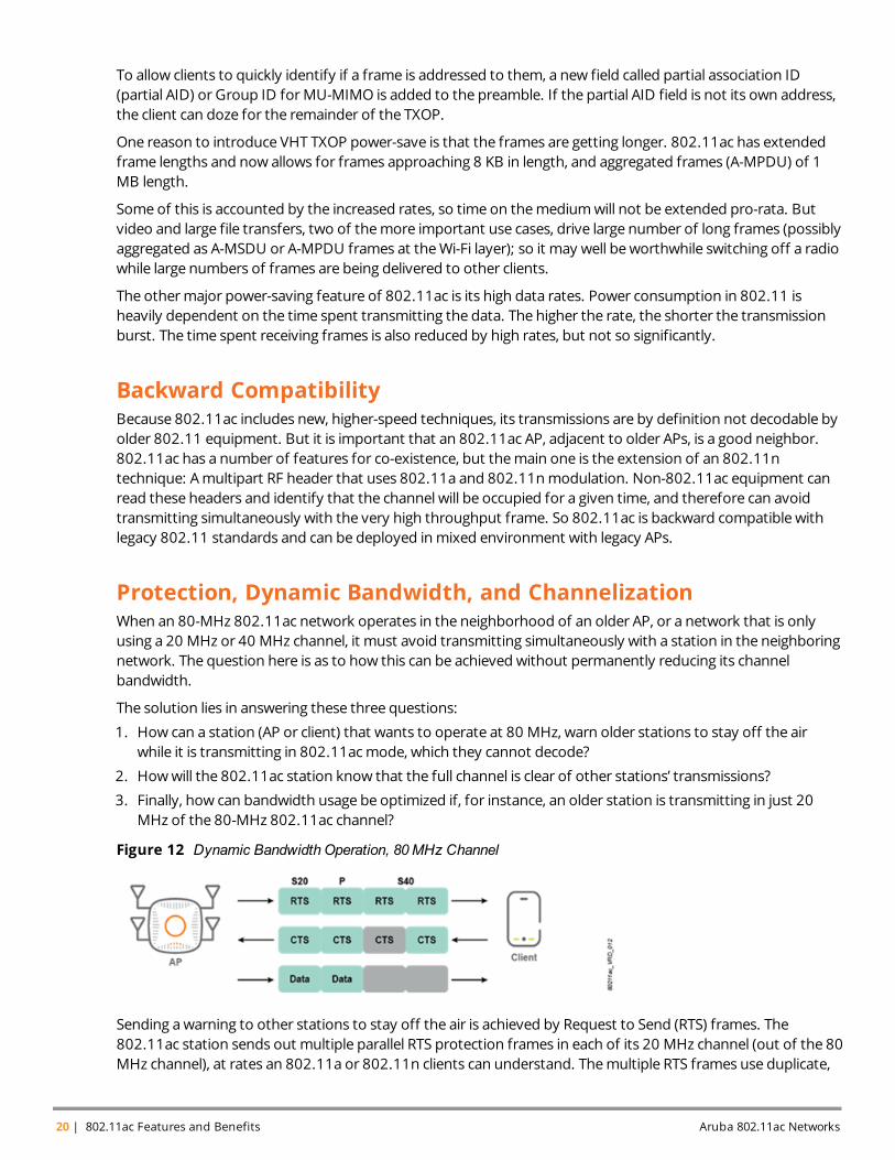
Figure 12 Dynamic Bandwidth Operation, 80MHz Channel
Sending awarning to other stations to stay off the air is achieved by Request to Send (RTS) frames. The802.11ac station sends out multiple parallel RTS protection frames in each of its 20 MHz channel (out of the 80MHz channel), at rates an 802.11a or 802.11n clients can understand. Themultiple RTS frames use duplicate,
quadruplicate, or octuplicate transmission. Before sending RTS, it performs clear channel assessment (CCA) tomake sure it cannot hear any transmissions in progress. On receiving the RTS frame, older stations know howlong to wait for the 802.11ac transmission.
Next, the recipient runs a CCA in each of the 20 MHz channels. The RTS frame format is extended so that theoriginator can indicate its channel options and replies with a Clear to Send (CTS) response to indicatewhether ithears transmissions in progress from any neighboring network. If not, the originator transmits the data frameusing the full bandwidth – 80 MHz in this case.
However, if the recipient does find transmissions in progress on any secondary channel, it can still continueresponding with CTS, while indicating which primary channels are clear (20 MHz or 40 MHz). Then, theoriginator can send its transmission using only the usable part of the 80 MHz channel.
Thismay force a reduction in channel from 80 MHz to 40 MHz or even 20 MHz, but the framewill betransmitted using airtime that would otherwise be unused. This feature is called dynamic bandwidth operation.
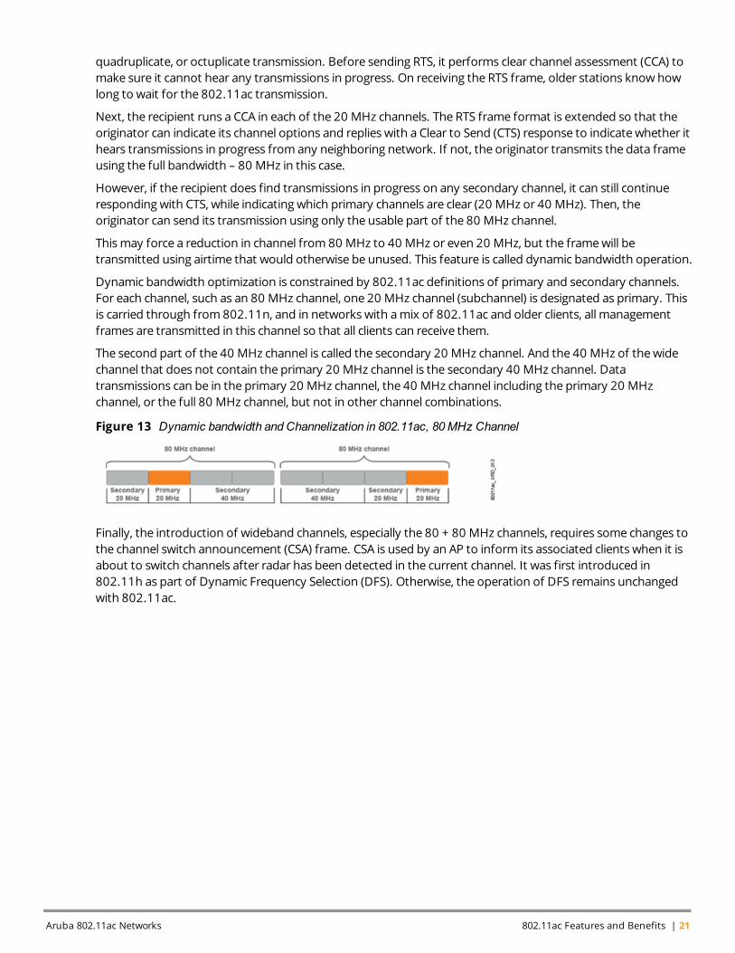
Dynamic bandwidth optimization is constrained by 802.11ac definitions of primary and secondary channels.For each channel, such as an 80 MHz channel, one 20 MHz channel (subchannel) is designated as primary. Thisis carried through from 802.11n, and in networks with amix of 802.11ac and older clients, all managementframes are transmitted in this channel so that all clients can receive them.
The second part of the 40 MHz channel is called the secondary 20 MHz channel. And the 40 MHz of thewidechannel that does not contain the primary 20 MHz channel is the secondary 40 MHz channel. Datatransmissions can be in the primary 20 MHz channel, the 40 MHz channel including the primary 20 MHzchannel, or the full 80 MHz channel, but not in other channel combinations.
Figure 13 Dynamic bandwidth and Channelization in 802.11ac, 80MHz Channel
Finally, the introduction of wideband channels, especially the 80 + 80 MHz channels, requires some changes tothe channel switch announcement (CSA) frame. CSA is used by an AP to inform its associated clients when it isabout to switch channels after radar has been detected in the current channel. It was first introduced in802.11h as part of Dynamic Frequency Selection (DFS). Otherwise, the operation of DFS remains unchangedwith 802.11ac.
Aruba 802.11ac Networks 802.11ac Features and Benefits | 21

Aruba 802.11ac Networks 802.11ac Planning and Deployment Guidelines | 23
Chapter 4802.11ac Planning and Deployment Guidelines
This chapter provides guidelines to plan and deploy 802.11acWLAN network. In general, 802.11acdeployment can be divided into the following two categories:
Greenfield:This is a deployment scenario where a network is being installed from scratch. There is no legacynetwork in place, whichmeans you can design a network with future technology support in mind. A campusthat does not have awireless network today would be considered a Greenfield environment.
Brownfield:This is a scenario where a legacy wireless network already exists and there is plan to deploy802.11ac. Because there is a dependency on how the network can be designed, a phased approach is typicallyadopted to roll out new technology. A campus already having 802.11 a/b/g- or 802.11n-based wirelessnetwork, and requiring you to implement 802.11ac is an example for amixed environment. Deploymentrecommendationsmight vary slightly based on the environment under consideration.
If you are going through a refresh cycle to transition to 802.11ac network from legacy network, Arubarecommends consideration of the following points before doing a one-to-one replacement of legacy APs with802.11ac APs:
l If the existing network is a capacity-based design in 5 GHz band, then one-for-one AP replacement with802.11ac AP is viable.
l If the existing network was originally planned for legacy 802.11a/b/g or is an 802.11n network planned for2.4 GHz based on coverage, then a network redesign is recommended. Redesigning includes a combinationof both physical and virtual survey.
Other factors to consider when planning for one-to-one replacement of legacy APs are:
Original AP density: If the answer to any of the following questions is yes, then one- to-one replacementmight not be a recommended best practice:
l Is your current network planned for coverage as opposed to capacity?
l Is there any coverage hole in your environment where you do not receive RF signals with currentdeployment?
l Are there any known RF-related issues such as poor connectivity and low performance?
l Do you want to provide seamless roaming experience to users?
l Do you need location-based services?
l Is there any architectural change in you facility like newwalls ormetal cabinets, which are resulting in poorWi-Fi connection?
Number of devices on the network: Number, type, capabilities, andmix (for example, single stream vsmultiple stream, 802.11a/b/g or 802.11n or 802.11ac) of devices that are expected to be part of the networkcan be a goodmetric to identify howmany APs you need in you network. If number of devices on yournetwork increases, you will need to addmore APs to support them, or otherwise therewill be a drop in networkperformance and users will start complaining for poor service. Also, you need to ensurewhat type of devicesyou expect on your network. 802.11ac clients aremuch faster and take less airtime compared to legacy clients.
Application type: You need to decide on what applications you want to support on your network. Enterpriseapplications likeMicrosoft Lync carry real-time voice and video traffic, which is delay-sensitive and requiresthorough planning regarding AP placements. Depending on different applications you want to support on yournetwork, identify howmuch bandwidth is required for each device. When you know the total number ofdevices on your network and the bandwidth required per device to support applications, you can plan on thenumber of clients associating per AP and total AP density required to cover the entire facility.
24 | 802.11ac Planning and DeploymentGuidelines Aruba 802.11ac Networks
Although Aruba APs can support up to 255 client devices per radio, in general it is recommended to plan for 40to 60 clients per radio so as to provide good user experience.
ArubaOS firmware version 6.4 and later used on 7200 and 7000 Series controller supports AppRF, a deeppacket inspection feature that allows you to classify and enforce policies on the applications running on yournetwork. AppRF supportsmore than 1400 applications and allows network administrators to create policiesfor blocking or permitting applications depending on your network policy. You can also create bandwidthcontracts to throttle traffic or apply Quality of Service (QoS) to prioritize application based on your use cases.ArubaNetworks, Inc., supportsMicrosoft Lync Software-Defined Networking (SDN) API. This provides visibilityinto Microsoft Lync traffic and helps prioritizeMicrosoft Lync traffic with respect to other background traffic sothat users can have high-quality voice and video calls. With SDN API, the Aruba Controller gets the real-timeMicrosoft Lync call quality metrics from theMicrosoft Lync servers. This allows network adminstrators toquickly identify and troubleshoot issues related to Microsoft Lync voice and video calls. If any type of voice,UCC, ormulticast applications are to be used over theWi-Fi infrastructure, this will help drive the design criteria.
After having understood the AP density requirements, the best practices and recommendations to deploy802.11ac network using Aruba controllers and APs are provided in the following sections.
This chapter covers the following sections:
l Wired Network Considerations
l RF Planning
l ForwardingMode Recommendations
l ChannelWidth Selection
l Capacity Planning
Wired Network ConsiderationsThis section provides guidelines that will help you plan and design your wired network infrastructure tosupport the deployment of 802.11ac wireless network.
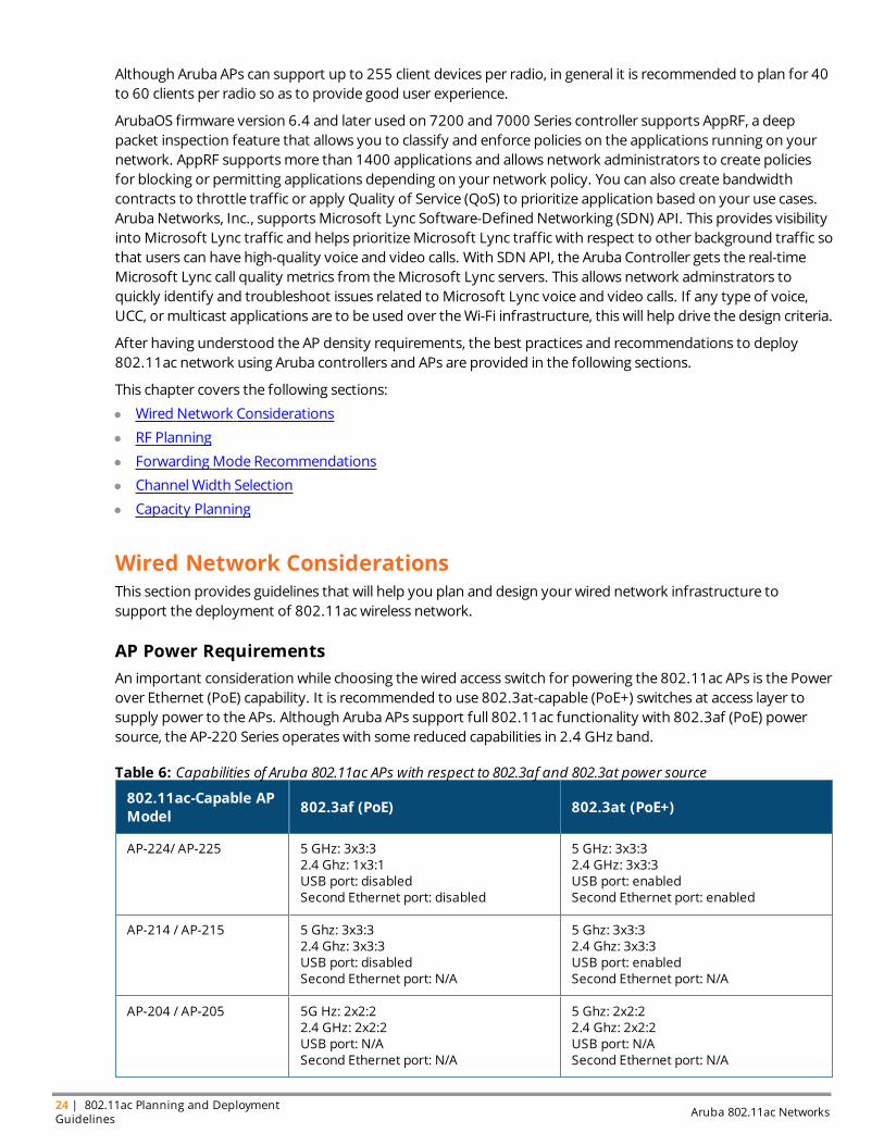
AP Power RequirementsAn important consideration while choosing thewired access switch for powering the 802.11ac APs is the Powerover Ethernet (PoE) capability. It is recommended to use 802.3at-capable (PoE+) switches at access layer tosupply power to the APs. Although Aruba APs support full 802.11ac functionality with 802.3af (PoE) powersource, the AP-220 Series operates with some reduced capabilities in 2.4 GHz band.
802.11ac-Capable APModel 802.3af (PoE) 802.3at (PoE+)
AP-224/ AP-225 5 GHz: 3x3:32.4 Ghz: 1x3:1USB port: disabledSecond Ethernet port: disabled
5 GHz: 3x3:32.4 GHz: 3x3:3USB port: enabledSecond Ethernet port: enabled
AP-214 / AP-215 5 Ghz: 3x3:32.4 Ghz: 3x3:3USB port: disabledSecond Ethernet port: N/A
5 Ghz: 3x3:32.4 Ghz: 3x3:3USB port: enabledSecond Ethernet port: N/A
AP-204 / AP-205 5G Hz: 2x2:22.4 GHz: 2x2:2USB port: N/ASecond Ethernet port: N/A
5 Ghz: 2x2:22.4 Ghz: 2x2:2USB port: N/ASecond Ethernet port: N/A
Table 6: Capabilities of Aruba 802.11ac APs with respect to 802.3af and 802.3at power source
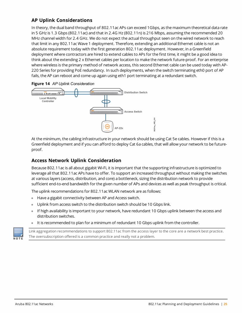
AP Uplink ConsiderationsIn theory, the dual band throughput of 802.11ac APs can exceed 1Gbps, as themaximum theoretical data ratein 5 GHz is 1.3 Gbps (802.11ac) and that in 2.4G Hz (802.11n) is 216 Mbps, assuming the recommended 20MHz channel width for 2.4 GHz. We do not expect the actual throughput seen on thewired network to reachthat limit in any 802.11acWave 1 deployment. Therefore, extending an additional Ethernet cable is not anabsolute requirement today with the first generation 802.11ac deployment. However, in a Greenfielddeployment where contractors are hired to extend cables to APs for the first time, it might be a good idea tothink about the extending 2 x Ethernet cables per location to make the network future-proof. For an enterprisewherewireless is the primary method of network access, this second Ethernet cable can be used today with AP-220 Series for providing PoE redundancy. In such deployments, when the switch terminating eth0 port of APfails, the AP can reboot and comeup again using eth1 port terminating at a redundant switch.
Figure 14 AP Uplink Consideration
At theminimum, the cabling infrastructure in your network should be using Cat 5e cables. However if this is aGreenfield deployment and if you can afford to deploy Cat 6a cables, that will allow your network to be future-proof.
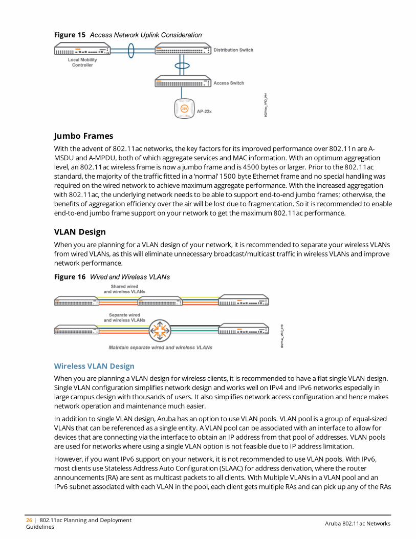
Access Network Uplink ConsiderationBecause 802.11ac is all about gigabit Wi-Fi, it is important that the supporting infrastructure is optimized toleverage all that 802.11ac APs have to offer. To support an increased throughput without making the switchesat various layers (access, distribution, and core) a bottleneck, sizing the distribution network to providesufficient end-to-end bandwidth for the given number of APs and devices as well as peak throughput is critical.
The uplink recommendations for 802.11acWLAN network are as follows:
l Have a gigabit connectivity between AP and Access switch.
l Uplink from access switch to the distribution switch should be 10 Gbps link.
l If high availability is important to your network, have redundant 10 Gbps uplink between the access anddistribution switches.
l It is recommended to plan for aminimumof redundant 10 Gbps uplink from the controller.
Link aggregation recommendations to support 802.11ac from the access layer to the core are a network best practice.The oversubscription offered is a common practice and really not a problem.
Aruba 802.11ac Networks 802.11ac Planning and Deployment Guidelines | 25
26 | 802.11ac Planning and DeploymentGuidelines Aruba 802.11ac Networks
Figure 15 Access Network Uplink Consideration
Jumbo FramesWith the advent of 802.11ac networks, the key factors for its improved performance over 802.11n are A-MSDU and A-MPDU, both of which aggregate services andMAC information. With an optimumaggregationlevel, an 802.11ac wireless frame is now a jumbo frame and is 4500 bytes or larger. Prior to the 802.11acstandard, themajority of the traffic fitted in a ‘normal’ 1500 byte Ethernet frame and no special handling wasrequired on thewired network to achievemaximumaggregate performance. With the increased aggregationwith 802.11ac, the underlying network needs to be able to support end-to-end jumbo frames; otherwise, thebenefits of aggregation efficiency over the air will be lost due to fragmentation. So it is recommended to enableend-to-end jumbo frame support on your network to get themaximum802.11ac performance.
VLAN DesignWhen you are planning for a VLAN design of your network, it is recommended to separate your wireless VLANsfromwired VLANs, as this will eliminate unnecessary broadcast/multicast traffic in wireless VLANs and improvenetwork performance.
Figure 16 Wired andWireless VLANs
Wireless VLAN DesignWhen you are planning a VLAN design for wireless clients, it is recommended to have a flat single VLAN design.Single VLAN configuration simplifies network design and works well on IPv4 and IPv6 networks especially inlarge campus design with thousands of users. It also simplifies network access configuration and hencemakesnetwork operation andmaintenancemuch easier.
In addition to single VLAN design, Aruba has an option to use VLAN pools. VLAN pool is a group of equal-sizedVLANs that can be referenced as a single entity. A VLAN pool can be associated with an interface to allow fordevices that are connecting via the interface to obtain an IP address from that pool of addresses. VLAN poolsare used for networks where using a single VLAN option is not feasible due to IP address limitation.
However, if you want IPv6 support on your network, it is not recommended to use VLAN pools. With IPv6,most clients use Stateless Address Auto Configuration (SLAAC) for address derivation, where the routerannouncements (RA) are sent asmulticast packets to all clients. With Multiple VLANs in a VLAN pool and anIPv6 subnet associated with each VLAN in the pool, each client getsmultiple RAs and can pick up any of the RAs
and derive an address from it. There is a very high probability that a client may pick an address in a VLAN thatwe did not associate it with. This breaks IPv6 connectivity.
So Aruba recommends using a single flat VLAN for wireless clients. To optimize thewireless performance, it isrecommended to use broadcast/multicast (BC/MC) optimization knobs of Aruba controller to preventunnecessary broadcast/multicast traffic fromoccupying spectrumbandwidth. Formore details, see theBroadcast/Multicast optimization section in Chapter 5: WLAN Optimizations.
RF PlanningWhen you are planning to deploy aWLAN network, it is important to understand how and where your APs willbemounted to have a seamlessWi-Fi experience. You should identify the attenuation and interference sourcesin you environment, which can degrade your network performance. Following section provides RF planningguidelines to deploy an 802.11acWLAN network.
AP Mounting RecommendationsIndoor APs are typically deployed in either of the followingmethods:
l Ceilingmount deployment
l Wall mount deployment
Aruba recommends against desk or cubiclemounts. These locations typically do not allow for a clear line-of-sight throughout the coverage area, which in turn can reduceWLAN performance.
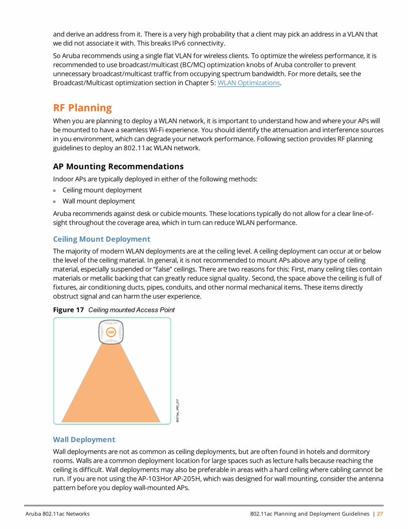
Ceiling Mount DeploymentThemajority of modernWLAN deployments are at the ceiling level. A ceiling deployment can occur at or belowthe level of the ceilingmaterial. In general, it is not recommended to mount APs above any type of ceilingmaterial, especially suspended or “false” ceilings. There are two reasons for this: First, many ceiling tiles containmaterials ormetallic backing that can greatly reduce signal quality. Second, the space above the ceiling is full offixtures, air conditioning ducts, pipes, conduits, and other normalmechanical items. These items directlyobstruct signal and can harm the user experience.
Figure 17 Ceilingmounted Access Point
Wall DeploymentWall deployments are not as common as ceiling deployments, but are often found in hotels and dormitoryrooms. Walls are a common deployment location for large spaces such as lecture halls because reaching theceiling is difficult. Wall deploymentsmay also be preferable in areas with a hard ceiling where cabling cannot berun. If you are not using the AP-103Hor AP-205H, which was designed for wall mounting, consider the antennapattern before you deploy wall-mounted APs.
Aruba 802.11ac Networks 802.11ac Planning and Deployment Guidelines | 27
28 | 802.11ac Planning and DeploymentGuidelines Aruba 802.11ac Networks
Figure 18 Wall Mounted Access Point
Site SurveyOne of the important steps in RF planning is site survey analysis, which helps to identify AP placements toprovide high-quality wireless experience throughout the facility. There are different types of site surveymethods available such as virtual site survey, passive site survey, active site survey, and spectrum clearing sitesurvey.
A virtual site survey, which is generally done using softwares like Aruba’s VisualRF Plan, can be a good startingpoint to identify the coverage pattern. It can generate heat map showing RSSI values and can also help ingenerating bill of material (BoM) for your project. Although virtual site survey is a quick way to simulate APplacements and understand coverage patterns, it is recommended to conduct a physical site survey to validatethe estimates of virtual site survey and verify the coverage and capacity of your network.
Formore details regarding wireless site survey, refer to the indoor site survey and planning VRD available at:http://community.arubanetworks.com/t5/Validated-Reference-Design/tkb-p/ArubaVDRs.
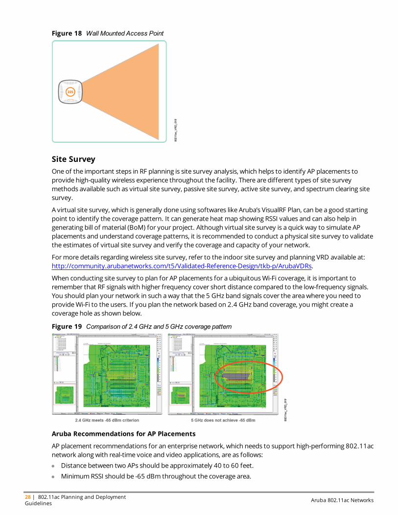
When conducting site survey to plan for AP placements for a ubiquitousWi-Fi coverage, it is important toremember that RF signals with higher frequency cover short distance compared to the low-frequency signals.You should plan your network in such away that the 5 GHz band signals cover the areawhere you need toprovideWi-Fi to the users. If you plan the network based on 2.4 GHz band coverage, youmight create acoverage hole as shown below.
Figure 19 Comparison of 2.4 GHz and 5GHz coverage pattern
Aruba Recommendations for AP Placements
AP placement recommendations for an enterprise network, which needs to support high-performing 802.11acnetwork along with real-time voice and video applications, are as follows:
l Distance between two APs should be approximately 40 to 60 feet.
l MinimumRSSI should be -65 dBm throughout the coverage area.
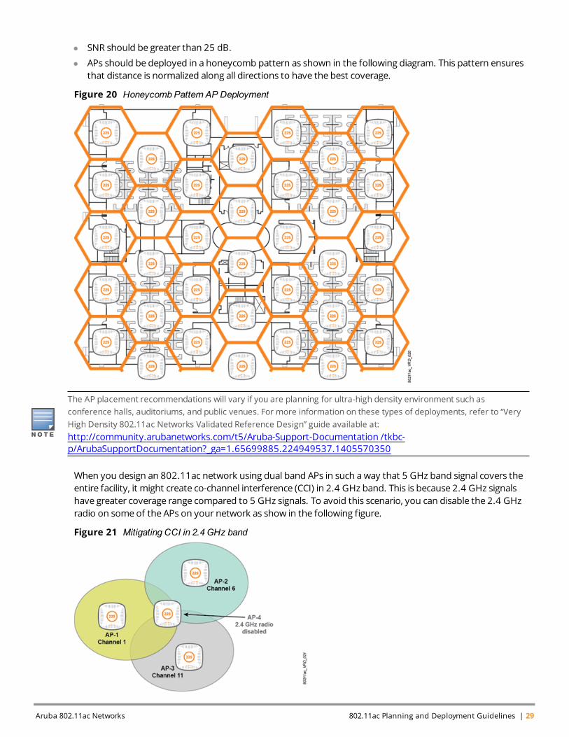
l SNR should be greater than 25 dB.
l APs should be deployed in a honeycomb pattern as shown in the following diagram. This pattern ensuresthat distance is normalized along all directions to have the best coverage.
Figure 20 Honeycomb Pattern AP Deployment
The AP placement recommendations will vary if you are planning for ultra-high density environment such asconference halls, auditoriums, and public venues. For more information on these types of deployments, refer to “VeryHigh Density 802.11ac Networks Validated Reference Design” guide available at:http://community.arubanetworks.com/t5/Aruba-Support-Documentation /tkbc-p/ArubaSupportDocumentation?_ga=1.65699885.224949537.1405570350
When you design an 802.11ac network using dual band APs in such away that 5 GHz band signal covers theentire facility, it might create co-channel interference (CCI) in 2.4 GHz band. This is because 2.4 GHz signalshave greater coverage range compared to 5 GHz signals. To avoid this scenario, you can disable the 2.4 GHzradio on some of the APs on your network as show in the following figure.
Figure 21 Mitigating CCI in 2.4 GHz band
Aruba 802.11ac Networks 802.11ac Planning and Deployment Guidelines | 29
30 | 802.11ac Planning and DeploymentGuidelines Aruba 802.11ac Networks
In this figure, as 3 APs are enough to have a 2.4 GHz coverage, you can disable the2.4 GHz radio on AP-4 to avoid co-channel interference. You can use the 2.4 GHz radio on AP-4 either as adedicated spectrummonitor to collect spectrum analysis data or as a dedicated airmonitor to performwirelessintrusion detection and wireless intrusion protection.
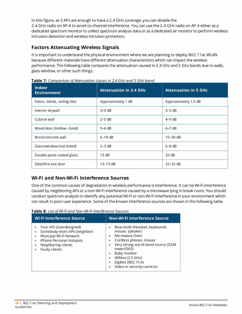
Factors Attenuating Wireless SignalsIt is important to understand the physical environment wherewe are planning to deploy 802.11acWLANbecause different materials have different attenuation characteristics which can impact thewirelessperformance. The following table compares the attenuation caused in 2.4 Ghz and 5 Ghz bands due to walls,glass window, or other such things.
IndoorEnvironment Attenuation in 2.4 GHz Attenuation in 5 GHz
Fabric, blinds, ceiling tiles Approximately 1 dB Approximately 1.5 dB
Interior drywall 3–4 dB 3–5 dB
Cubicle wall 2–5 dB 4–9 dB
Wood door (Hollow –Solid) 3–4 dB 6–7 dB
Brick/concrete wall 6–18 dB 10–30 dB
Glass/window (not tinted) 2–3 dB 6–8 dB
Double-pane coated glass 13 dB 20 dB
Steel/fire exit door 13–19 dB 25–32 dB
Table 7: Comparison of Attenuation Losses in 2.4 GHz and 5 GHz band
Wi-Fi and Non-Wi-Fi Interference SourcesOne of the common causes of degradation in wireless performance is interference. It can beWi-Fi interferencecaused by neighboring APs or a non-Wi-Fi interference caused by amicrowave lying in break room. You shouldconduct spectrum analysis to identify any potential Wi-Fi or non-Wi-Fi interference in your environment whichcan result in poor user experience. Some of the known interference sources are shown in the following table.
Wi-Fi Interference Source Non-Wi-Fi Interference Source
l Your APs (overdesigned)l Somebody else’s APs (neighbor)l Muncipal Wi-Fi Networkl iPhone Personal Hotspotsl Neighboring clientsl Faulty clients
l Blue-tooth (headset, keyboards,mouse, speaker)
l Microwave Ovenl Cordless phones, mousel Very strong out-of-band source (GSM
tower/DAS)l Baby monitorl WiMax (2.5 GHz)l ZigBee (802.15.4)l Video or security cameras
Table 8: List of Wi-Fi and Non-Wi-Fi Interference Sources
Aruba APs can act as a dedicated spectrum analyzer which will scan all the Wi-Fi channel in regulatory domain or it canat as a hybrid spectrum analyzer where the AP will serve clients and simultaneously scan the channel on which it isserving clients. For more details about SpectrumMonitors, refer to “Aruba 802.11n Networks Validated ReferenceDesign” document available at: http://community.arubanetworks.com/t5/Validated-Reference-Design/tkb-p/ArubaVDRs.
Forwarding Mode RecommendationsFor campus AP deployment, Aruba supports three different forwardingmode—Tunnel Mode, Decrypt-Tunnelmode, and Bridgemode.
In general, bridge mode is not recommended to be used in campus environments.
This section provides information on themost common AP forwardingmodes and the recommendedmodefor 802.11ac deployments.
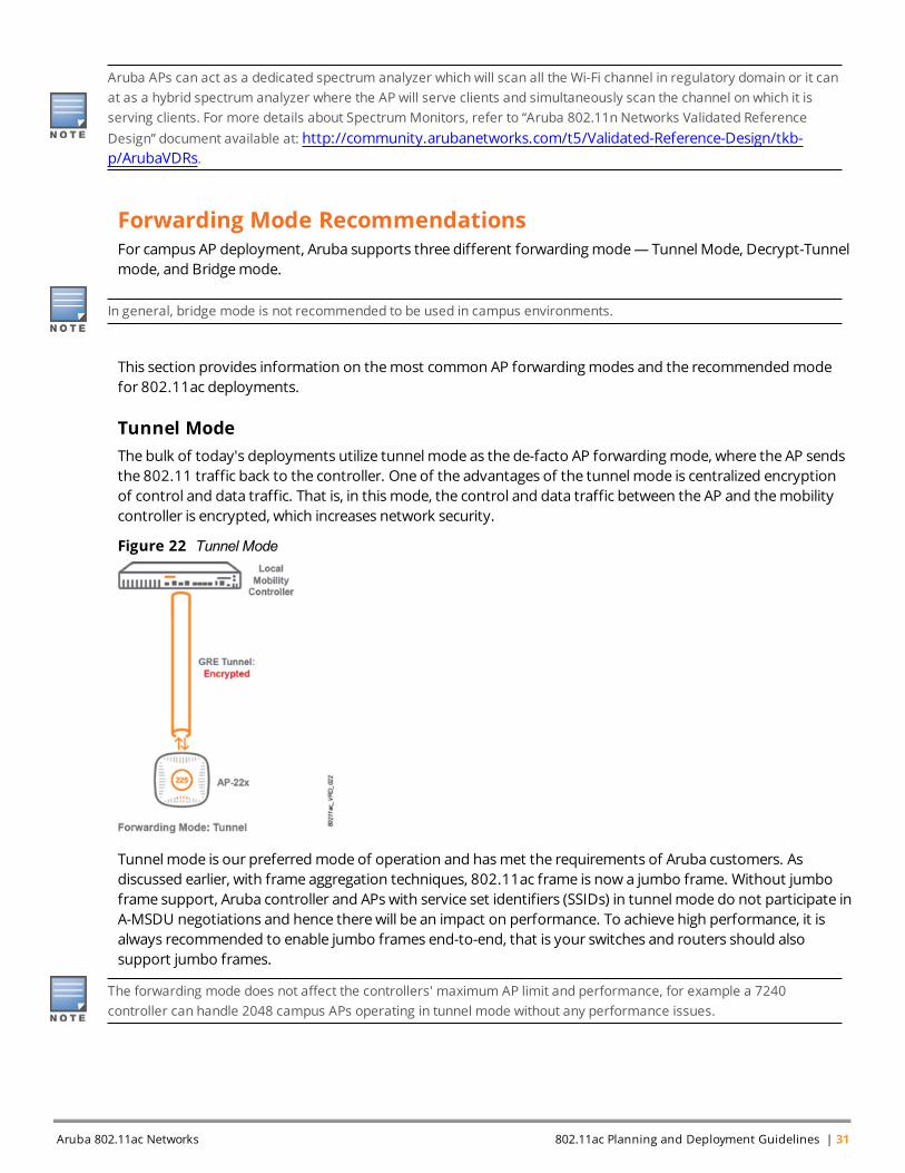
Tunnel ModeThe bulk of today's deployments utilize tunnelmode as the de-facto AP forwardingmode, where the AP sendsthe 802.11 traffic back to the controller. One of the advantages of the tunnelmode is centralized encryptionof control and data traffic. That is, in thismode, the control and data traffic between the AP and themobilitycontroller is encrypted, which increases network security.
Figure 22 Tunnel Mode
Tunnelmode is our preferredmode of operation and hasmet the requirements of Aruba customers. Asdiscussed earlier, with frame aggregation techniques, 802.11ac frame is now a jumbo frame. Without jumboframe support, Aruba controller and APs with service set identifiers (SSIDs) in tunnelmode do not participate inA-MSDU negotiations and hence therewill be an impact on performance. To achieve high performance, it isalways recommended to enable jumbo frames end-to-end, that is your switches and routers should alsosupport jumbo frames.
The forwarding mode does not affect the controllers' maximum AP limit and performance, for example a 7240controller can handle 2048 campus APs operating in tunnel mode without any performance issues.
Aruba 802.11ac Networks 802.11ac Planning and Deployment Guidelines | 31
32 | 802.11ac Planning and DeploymentGuidelines Aruba 802.11ac Networks
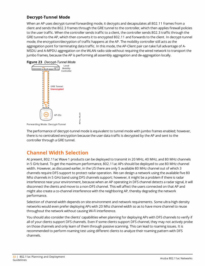
Decrypt-Tunnel ModeWhen an AP uses decrypt-tunnel forwardingmode, it decrypts and decapsulates all 802.11 frames from aclient and sends the 802.3 frames through theGRE tunnel to the controller, which then applies firewall policiesto the user traffic. When the controller sends traffic to a client, the controller sends 802.3 traffic through theGRE tunnel to the AP, which then converts it to encrypted 802.11 and forwards to the client. In decrypt-tunnelmode, the encryption/decryption of traffic happens at the AP. Themobility controller still acts as theaggregation point for terminating data traffic. In thismode, the AP-Client pair can take full advantage of A-MSDU and A-MPDU aggregation on theWLAN radio sidewithout requiring thewired network to transport thejumbo frames, because the AP is performing all assembly aggregation and de-aggregation locally.
Figure 23 Decrypt-Tunnel Mode
The performance of decrypt-tunnelmode is equivalent to tunnelmodewith jumbo frames enabled; however,there is no centralized encryption because the user data traffic is decrypted by the AP and sent to thecontroller through aGRE tunnel.
Channel Width SelectionAt present, 802.11acWave 1 products can be deployed to transmit in 20 MHz, 40 MHz, and 80 MHz channelsin 5 GHz band. To get themaximumperformance, 802.11ac APs should be deployed to use 80 MHz channelwidth. However, as discussed earlier, in the US there are only 5 available 80 MHz channel out of which 3channels require DFS support to protect radar operation. We can design a network using the available five 80Mhz channels in 5 GHz band using DFS channels support; however, it might be a problem if there is radarinterference near your environment, becausewhen an AP operating in DFS channel detects a radar signal, it willdisconnect the clients andmove to a non-DFS channel. This will affect the users connected on that AP andmight also create a co-channel interferencewith the neighboring AP, thereby degrading the networkperformance.
Selection of channel width depends on site environment and network requirements. Some ultra-high densitynetworks would even prefer deploying APs with 20 Mhz channel width so as to havemore channel to reusethroughout the network without causingWi-Fi interference.
You should also consider the clients' capabilities when planning for deploying APs with DFS channels to verify ifall of your clients support DFS channels. Even if some clients support DFS channel, they may not actively probeon those channels and only learn of them through passive scanning. This can lead to roaming issues. It isrecommended to perform roaming test using different clients to analyze their roaming pattern with DFSchannels.
With 802.11ac standard, Federal Communications Commission (FCC) allowed the use of Channel 144. However, legacyand 802.11n clients do not support Channel 144 and hence they cannot associate to the AP if its primary channel isChannel 144. So make sure when you plan for 80 Mhz channel, avoid using channel 144 as primary channel.
General guidelines for channel width selection is as follows:
Channel Width Selection for Greenfield Deployments: When planning for Greenfield deployment, youcan go with 80 Mhz channel width deployment; however, DFS channels need to be assessed on a case-by-casebasis. Certain verticals like healthcare try to avoid deploying APs in theDFS channel to avoid radar-triggeredchannel shifts, given that mission-critical services like heart ratemonitors and IV pumps are running onWi-Fi. Incasewhere use of DFS channels is not feasible either due to regulatory domain constraints or due to radarinterference, it is recommended to use 40 MHz channel width so that more channels are available for reuse.
Channel Width Selection for Brownfield Deployments: In a Brownfield deployment, where the customerismigrating from a legacy 802.11a/b/g/n AP to 802.11ac AP and therewill be amix of Wi-Fi technologies, youcan utilize 80 MHz or 40 Mhz channels.
If you are utilizing thewider 80 MHz channels, then you should perform interoperability tests with a sample setof your client devices to ensure that the legacy clients do not cause implementation issues. In such case, youwould need to limit your network to 40 MHz channels until your clients are updated. This ismore pronouncedin environments such as universities, where the IT department does not have control over the devices thatusers bring in.
For environments where IT has control over the device, it is recommended to update the client wireless chipsetdriver to the latest version and run some tests between 802.11n and 802.11ac APs when 802.11ac isdeployed using 80 MHz channels. It is also recommended to deploy the new 802.11ac APs together in an arearather than amix (salt and pepper) of legacy and 802.11ac APs.
Capacity planningWhen planning for capacity, themost important things to consider are howmany devices will access thenetwork and what will be the type of client mix. Generally, people carry at least three devices – for example, alaptop, a tablet, and a smartphone. The number of devices per user also has ramifications in the design ofVLANs and subnets. Expected number of active devices trying to access the network will be one of themetricsto calculate the required AP density.
When calculating AP density for a capacity design, plan to have around 40 to 60 active devices per radio.Although APs can support 255 associated devices per radio, having less users will allow facilitation ofbandwidth requirements and provides for high quality user experience. It is also important to select rightdevices to support your network requirements. ArubaNetworks, Inc., have awide portfolio of Controllers andAPs that allows you to select the best combination of devices to meet your network requirements.
For detailed information about WLAN products, refer to http://www.arubanetworks.com/products/.
Active devices are the clients which are associated to the AP and actively sending and receiving data on the wirelessnetwork. Associated devices are clients that are just associated to the AP andmight not be involved in active datatransfer activity.
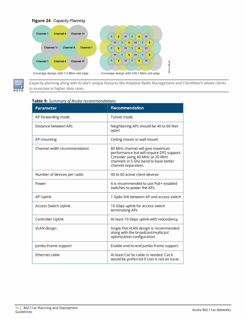
As can be seen from the following figure, typically in a capacity-based design, you will have to deploy more APscompared to coverage-based design. In a capacity design, users are generally associated with high data ratesand get better wireless experience.
Aruba 802.11ac Networks 802.11ac Planning and Deployment Guidelines | 33
34 | 802.11ac Planning and DeploymentGuidelines Aruba 802.11ac Networks
Figure 24 Capacity Planning
Capacity planning along with Aruba’s unique features like Adaptive Radio Management and ClientMatch allows clientsto associate at higher data rates.
Parameter Recommendation
AP forwarding mode Tunnel mode
Distance between APs Neighboring APs should be 40 to 60 feetapart
AP mounting Ceiling mount or wall mount
Channel width recommendation 80 MHz channel will give maximumperformance but will require DFS support.Consider using 40 MHz or 20 MHzchannels in 5 Ghz band to have betterchannel separation.
Number of devices per radio 40 to 60 active client devices
Power It is recommended to use PoE+ enabledswitches to power the APs.
AP Uplink 1 Gpbs link between AP and access switch
Access Switch Uplink 10 Gbps uplink for access switchterminating APs
Controller Uplink At least 10 Gbps uplink with redundancy
VLAN design Single Flat VLAN design is recommendedalong with the broadcast/multicastoptimization configuration.
Jumbo Frame support Enable end-to-end jumbo frame support.
Ethernet cable At least Cat 5e cable is needed. Cat 6would be preferred if cost is not an issue.
Table 9: Summary of Aruba recommendations
Aruba 802.11ac Networks WLAN Optimizations | 35
Chapter 5WLAN Optimizations
This chapter provides guidelines and recommendations on some of the unique features supported by Aruba’sWLAN architecture to optimizeWLAN network performance. Wewill provide recommendations for followingtopics:
l Adaptive Radio Management (ARM)
l ClientMatch (CM)
l Broadcast/Multicast Optimization
l DynamicMulticast Optimization
l Traffic Shaping
l QoS
Adaptive Radio Management (ARM)Radio Frequency (RF) spectrum is a limited and shared resource, and asmany factors as possiblemust becontrolled to provide an optimal user experience. ArubaOS supports Adaptive Radio Management (ARM)feature that allowsWLAN infrastructure to make decisions about radio resources and client connectionswithout manual intervention by network administrators or client-side software.
Aruba APs or AirMonitors (AM) periodically scan the networks to gather information about the RFenvironment. This information is then fed to the ARM algorithm that optimizes the network and improves theuser experience. ARM is a part of the base ArubaOS™ and is available on all ArubaMobility Controllers and APs.
One of the important functions of ARM is to dynamically select channel for the APs as ameans to avoidWi-Fiand non-Wi-Fi interference and to adjust transmit power so as to mitigate the issues of coverage hole andoptimize network performance.
Channel and Power SettingsInitially, when 802.11nWLANswere introduced, network administrators had to manually build a channel andpower plan based on onetime site survey. The following figure shows a typical 2.4 Ghz RF channel plan wherethe network engineermust manually change the power and channel on each AP. Remember that in the 2.4GHz band, only three channels are practical for use inmost regulatory domains. A similar plan exists in the 5GHz band, but generally more channels are available.

36 | WLAN Optimizations Aruba 802.11ac Networks
Figure 25 Typical Channel Plan 20MHz channel width
After all the APs are configured, they will remain in this state until the administrator changes themmanually.
The problemwithmanual channel plans is that they were based on a snapshot in time of the RF environment.The presence of devices, walls, cubes, office doors that open and close, microwave ovens, and even the humanbody, all have an effect on the RF environment. This fluid environment generally cannot be tested andcompensated for in a static channel and power plan. First of all, it is very time consuming to configure each andevery AP on the network manually. Additionally, the static plan does not automatically work around AP failureand new sources of interference. If an AP in a particular area fails, the administrator will have to manuallyincrease power on the surrounding APs to compensate for the RF “hole” until that AP can be replaced. Ifpersistent interferencemakes a channel unusable, that APmust be configured with a new channel. Newchannels typically have a cascade effect and require that changes bemade to other adjacent APs in the area,eventually propagating through the entire local wireless network. Consider the scenario shown in the followingfigure, when awireless camera interferes with the AP's channel, the entire planmust be adjusted tocompensate.
Figure 26 Dynamic Channel Selection Using ARM to Avoid Interference
At themost basic level, ARM allows the network to considerWi-Fi and non-Wi-Fi interference and other APsbefore it configures power and channel settings for APs. APs and AMs continuously scan the environment. Ifan AP goes down, ARM automatically fills in the “RF hole.” ARM increases power on the surrounding APs untilthe original AP is restored. When the AP is restored, ARM sets the network to the new optimal setting. If aninterfering device (Wi-Fi or non-Wi-Fi) appears on the network, such as awireless camera that consumes achannel, ARM adjusts the AP channels appropriately.
The important thing here is that the ArubaWLAN controller learns networkwide information and takes decisiondynamically to change channel and power of the APs to avoid interference and improve network performance.
ClientMatchThere is a better understanding of all the improvements that comewith 802.11ac standard and how clientscan get higher data rates. Even though clients can achieve high speeds, it is difficult to ensure that each client ina network has a good user experience especially when we have smartphones, tablets, and other clients thatcontrol their own connectivity and roaming decision. Prior to ClientMatch, clients were steered to the best APonly during the initial association. In case of any RF environment changes, for example if SNR or signal level ofclient falls below a certain level, the AP will not make any intelligent decision on steering the client to a better APand will rely on clients to make its own decision. Similarly, during roaming scenario, some clients stick to an oldAP even when it can hear another AP with better signal strength. This can result in poor connectivity and canbring down the performance of other associated clients on that AP.
ClientMatch technology fromArubaNetworks, Inc., is a patented, standards-based RF managementtechnology that puts theWLAN infrastructure in control of client connectivity and roaming. Leveraging asystem-level view of the network, ClientMatchmonitors clients and automatically matches them to the rightradio on the right AP, boosting the overall WLAN performance and delivering a consistent, predictableperformance to every user and client, while eliminating the sticky client problem for good. ClientMatch is anArubaOS function and no software changes are required on the client side to achieve this functionality.ClientMatch works with all clients, including all the latest 802.11ac clients across all operating systems.ClientMatch is supported on ArubaOS 6.3.0 and later firmware versions.
ClientMatch leverages industry standards to accomplish its monitoring and control functions, including the 802.11k andthe 802.11v standards. As a result, IT is assured of interoperability with no additional overhead.
ClientMatch CapabilitiesClientMatch has number of capabilities that enables it to connect the client to the best AP and improve theuser experience. In general, here are some of the client/AP mismatch conditions that aremanaged byClientMatch.
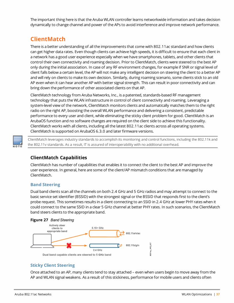
Band SteeringDual band clients scan all the channels on both 2.4 GHz and 5 GHz radios andmay attempt to connect to thebasic service set identifier (BSSID) with the strongest signal or the BSSID that responds first to the client’sprobe request. This sometimes results in a client connecting to an SSID in 2.4 GHz at lower PHY rates when itcould connect to the same SSID in a clear 5 GHz channel at better PHY rates. In such scenarios, the ClientMatchband steers clients to the appropriate band.
Figure 27 Band Steering
Sticky Client SteeringOnce attached to an AP, many clients tend to stay attached – even when users begin to move away from theAP andWLAN signal weakens. As a result of this stickiness, performance formobile users and clients often
Aruba 802.11ac Networks WLAN Optimizations | 37
38 | WLAN Optimizations Aruba 802.11ac Networks
degrades, dragging down overall network throughput. ClientMatch intelligently steers such sticky clients to abetter AP and improves user experience and overall network performance.
Dynamic Load BalancingDynamic Load Balancing enables APs and controllers to dynamically load-balanceWi-Fi clients to the APs withinthe same RF neighborhood on underutilized channels. This technique helps stationary and roaming clients indense office environments, conference rooms, lecture halls, and environments that have high-bandwidthapplications owing to client density being dynamically balanced among the APs in the same vicinity.ClientMatch performs dynamic load balancing and ensures that individual APs are not overtaxed and clientperformance is continually optimized, even in dense environments.
All the featuresmentioned herework dynamically and improve client and network performance. Some of thebenefits of ClientMatch are:
l Faster network connections for individual clients, which translates to better overall performance foreveryone.
l Vastly improved performance for roaming smartphones, tablets, and laptops.
l A standards-based solution that works with all client types, including 802.11a/b/g, 802.11n, and 802.11acclients.
l There is no need to purchase new clients or install new software.
l Operates automatically, so there is nothing for IT to configure, monitor, ormanage.
l The network continuously optimizes client connections so overall network capacity and performanceremains consistent.
l Dramatically reduced help desk calls due to a better user experience.
ClientMatch is enabled by default and supports band steering, sticky client steering, and dynamic load balancingfeatures on AP-200 Series (802.11ac APs). The legacyArubaOS knobs to perform similar functions (band steering, clienthandoff assist, and spectrum load balancing) do not work with AP-200 Series.
Formore information on how ClientMatch configuration can be optimized for roaming, refer to the “RF andRoaming Optimization for Aruba 802.11ac Networks” VRD available at:http://community.arubanetworks.com/t5/Validated-Reference-Design/tkb-p/ArubaVDRs.
Broadcast/Multicast (BC/MC) OptimizationIn the VLAN design section, we recommended using a single flat VLAN design for wireless users. In a high-density environment, this can create large broadcast domain. To control the unnecessary broadcast andmulticast traffic from consuming airtime, Aruba recommends configuring the broadcast/multicast optimizationknobs as discussed in the following table.
Feature Default Value RecommendedValue Comments
Convert Broadcast ARPRequests to Unicast
Enable Enable Helps to convert broadcast ARP andDHCP packets to unicast
Drop Broadcast andMulticast
Disable Enable Restricts all the broadcast andmulticast traffic flooding into APtunnels(“Convert Broadcast ARP to Unicast”feature must be enabled)
Table 10: Recommendations for Broadcast/Multicast Optimization Knobs
AirGroupAfter you configure the broadcast/multicast optimization knobs, we drop the broadcast/multicast traffic in theair. However, in enterprise or campus deployments, multicast-based services like DLNA, MDNS, and other zero-configuration protocols are essential. To allow such services for AirPlay and Chromecast type of application,ArubaWLAN with AirGroup technology enables context-aware access to DLNA, Apple Bonjour, and othershared devices without constrainingWLAN performance.
When AirGroup is enabled, the controllermaintains the list of the servers and clients that are using one of themulticast services. Each time a new client tries to access a service, or a server broadcasts the service, thecontroller stores it and proxy it on behalf of clients or servers. When you think about thousands of users in thecampus environment and hundreds of servers, AirGroup can save significant bandwidth on wired and wirelessside.
Feature Default Value Recommended Value Comments
AirGroup Disable Enable it if MDNS, DLNA orother zero-configurationservices are needed.
Allows AirPlay and Chromecast type ofapplications even if “drop broadcast andmulticast” is enabled
Table 11: AirGroup Recommendation
Dynamic Multicast Optimization (DMO)AirGroup helps to allow and optimizemulticast-based services like Airplay and Chromecast. However, in largeenterprises or campus networks, there could be other type of multicast traffic that needs to be allowed. Manycompanies or universities havemulticast video streams running in their network for business and educationalpurpose. Theremight be other custom applications that runs onmulticast. To meet these requirements, Arubacontroller provides knobs to optimizemulticast traffic over the air.
This section provides details about the following knobs:
l DynamicMulticast Optimization
l Multicast RateOptimization
Dynamic Multicast OptimizationThe 802.11 standard states that multicast overWLANmust be transmitted at the lowest basic rate so that allthe clients are able to decode it. The low transmission rate results in increased airtime utilization, and decreasedoverall throughput. Due to decrease in speed, it is advisable to transformmulticast traffic to unicast when afew clients have subscribed to amulticast stream.
Aruba 802.11ac Networks WLAN Optimizations | 39

40 | WLAN Optimizations Aruba 802.11ac Networks
Figure 28 Multicast Traffic Flow inWLAN With andWithout Optimization
The previous figure illustrates howDynamicMulticast Optimization (DMO) parameter convertsmulticastpackets to unicast and transmits it at a higher unicast rate over the air. In case of tunnelmode, the conversionis executed in the Aruba controller while in Decrypt-Tunnelmode, it is executed at the AP level. In Decrypt-tunnelmode, as conversion of multicast traffic to unicast is distributed acrossmultiple APs, it is known asDistributed DynamicMulticast Optimization (D-DMO). By default, DMO threshold has a default value of sixclients. When threshold is reached, multicast traffic will be sent as is to other clients. The value of theDMOthreshold should be high enough to match the expected number of clients on an AP.
IGMP snooping or IGMP proxy needs to be enabled for DMO to work. IGMP refers to the Internet GroupManagementProtocol. Multicast stream should be prioritized by configuring uplink ACL and correct Wi-Fi Multimedia (WMM)parameter to match DSCP values.
Multicast Rate OptimizationMulticast rate optimization keeps track of the transmit rates sustainable for each associated client and uses thehighest possible common rate formulticast transmission. For example, if all the clients connected to the virtualaccess point (VAP) are transmitting at a data rate of 24 Mbps or higher, multicast frames are transmitted at 24Mbps, rather than the lowest basic rate, which ranges between 1 Mbps and 6 Mbps.
Multicast Rate Optimization should be enabled along with DMO to optimize the multicast traffic when the DMO clientthreshold is hit.
Feature Default Value Recommended Value Comments
DynamicMulticastOptimization(DMO)
Disable l Enable it if multicaststreaming is needed.
l Set DMO clientthreshold to 80.
l Prioritize multicaststream using controlleruplink access controllist (ACL).
l Converts multicast frames to unicastframes to deliver them at higher rates
NOTE:l IGMP snooping or proxy needs to be
enabled for DMO to work.
Multicast RateOptimization
Disable Enable l Sends multicast frames at highestpossible common rate
l Enable it even if DMO is enabled.
Table 12: Multicast Traffic Optimization Recommendation
Depending on your network requirements, you will have to configure some or all of the followingbroadcast/multicast optimization knobs:
l Convert Broadcast ARP Requests to Unicast
l Drop Broadcast andMulticast
l AirGroup
l DynamicMulticast Optimization (DMO)
l Multicast RateOptimization
Traffic ShapingWi-Fi uses a sharedmedium and is used by many different client types and applications. So, fair access to senddata becomes critically important, especially during times of high contention amongst multiple clients. First, it isimportant that all clients receive access to that mediumwhen they have data to transmit. At the same time, it isalso important that high-speed clients can take advantage of their speed without being unduly slowed bylegacy clients that unfairly consume airtime.
Following traffic shaping policies can be applied to Aruba APs:
l Default access: Traffic shaping is disabled, and client performance is dependent onMAC contentionresolution. Thismight result in less-capable clients gettingmore time on the air than faster clients, therebydecreasing the aggregate network performance.
l Fair access: Each client gets the same airtime, regardless of client capability and capacity. This option isuseful in environments like a training facility or examhall, where amix of legacy, 802.11n ,and 802.11acclients need equal amount of network resources, regardless of their capabilities.
l Preferred access: In preferred access, more airtime is allocated to the clients with higher speeds – that is,802.11ac clients will get more airtime compared to 802.11n and legacy clients. Thismode gives the highestaggregate network performance but your legacy clientsmight get less performance.
It is recommend to use fair access traffic shaping policy to provide equal airtime to each client irrespective oftheir 802.11 capabilities (Legacy vs. 802.11n vs. 802.11ac).
Wi-Fi Multimedia and Quality of Service (QoS)Quality of service (QoS) is a set of packet markings and queuingmechanisms that prioritize classes of trafficthrough the network. Wi-Fi Multimedia (WMM) is based on the 802.11e amendment. It is a system formarkingtraffic as higher priority and adjusting the packet timers to allow delay-sensitive data to have precedence on
Aruba 802.11ac Networks WLAN Optimizations | 41
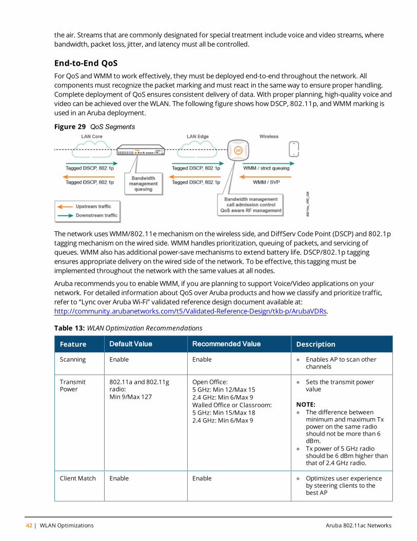
42 | WLAN Optimizations Aruba 802.11ac Networks
the air. Streams that are commonly designated for special treatment include voice and video streams, wherebandwidth, packet loss, jitter, and latency must all be controlled.
End-to-End QoSFor QoS andWMM to work effectively, they must be deployed end-to-end throughout the network. Allcomponentsmust recognize the packet marking andmust react in the sameway to ensure proper handling.Complete deployment of QoS ensures consistent delivery of data. With proper planning, high-quality voice andvideo can be achieved over theWLAN. The following figure shows howDSCP, 802.11p, andWMMmarking isused in an Aruba deployment.
Figure 29 QoS Segments
The network usesWMM/802.11emechanism on thewireless side, and DiffServ Code Point (DSCP) and 802.1ptaggingmechanism on thewired side. WMM handles prioritization, queuing of packets, and servicing ofqueues. WMM also has additional power-savemechanisms to extend battery life. DSCP/802.1p taggingensures appropriate delivery on thewired side of the network. To be effective, this taggingmust beimplemented throughout the network with the same values at all nodes.
Aruba recommends you to enableWMM, if you are planning to support Voice/Video applications on yournetwork. For detailed information about QoS over Aruba products and howwe classify and prioritize traffic,refer to “Lync over ArubaWi-Fi” validated reference design document available at:http://community.arubanetworks.com/t5/Validated-Reference-Design/tkb-p/ArubaVDRs.
Feature Default Value Recommended Value Description
Scanning Enable Enable l Enables AP to scan otherchannels
TransmitPower
802.11a and 802.11gradio:Min 9/Max 127
Open Office:5 GHz: Min 12/Max 152.4 GHz: Min 6/Max 9Walled Office or Classroom:5 GHz: Min 15/Max 182.4 GHz: Min 6/Max 9
l Sets the transmit powervalue
NOTE:l The difference between
minimum andmaximum Txpower on the same radioshould not be more than 6dBm.
l Tx power of 5 GHz radioshould be 6 dBm higher thanthat of 2.4 GHz radio.
Client Match Enable Enable l Optimizes user experienceby steering clients to thebest AP
Table 13: WLANOptimization Recommendations

Feature Default Value Recommended Value Description
ConvertBroadcastARP Requeststo Unicast
Enable Enable l Helps to convert broadcastARP and DHCP packets tounicast
DropBroadcast andMulticast
Disable Enable l Restricts all the broadcastandmulticast traffic floodinginto AP tunnels (“ConvertBroadcast ARP Requests toUnicast” feature must beenabled)
AirGroup Disable Enable it if MDNS, DLNA or otherzero-configuration services areneeded.
l Allows Airplay andChromeCast type ofapplications even if “DropBroadcast andMulticast”feature is enabled
DynamicMulticastOptimization(DMO)
Disable l Enable it if multicaststreaming is needed.
l Set DMO client threshold to80.
l Prioritize multicast streamusing controller uplink ACL.
l Converts multicast frames tounicast frames to deliverthem at higher rates
l IGMP Snooping or Proxyfeature needs to be enabledfor DMO to work
Multicast RateOptimization
Disable Enable l Sends multicast frames atthe highest possiblecommon rate
l Enable it even if DMO isenabled
AirtimeFairness
Default Access Fair Access l Provides equal air time to allthe clients
WMM Disable Enable it if you want to prioritizevoice/video traffic on yournetwork.
l Enables WMM capabilities toprioritize voice/video traffic
Table 13: WLANOptimization Recommendations
Aruba 802.11ac Networks WLAN Optimizations | 43