artificial heart valve turbulence measurement device project stuf… · artificial heart valve...
TRANSCRIPT

Artificial Heart Valve Turbulence Measurement Device
Team 12:Drew SeilsShane Tornifoglio

Objectives
Variable flow rate for re-circulated bloodAble to put commercial heart valves in-line for testingDisplay clotting factor levels and flow rateUtilize minimal RBC stress pumpWork with actual blood (clotting properties)Maintain homeostasis (max/min pressure, temperature)

Method of Measurement
To measure turbulence the device has been designed to measure the amount of free hemoglobin in the blood, released from ruptured RBC’s.For this purpose the team has employed the use of the Orsense NBM-200MP

Orsense NBM-200MP
The device is a noninvasive monitoring system that measures light absorption and scattering as the beam passes through the thumb of the patient. This device can however be applied to the soft tubing used in this heart valve device.The amount of light absorbed by the erythrocytes is the indicator for hemoglobin levels.

Orsense NBM-200MP
The sensor will be mounted within the artificial valve testing device and the monitor will be located externally.

Medtronic Bio-Pump Plus
The blood pump chosen for this device is a centrifugal pump, which eliminates the need for rollers or impellers to push blood through a tube, minimizing RBC stress.Blood enters through the top andis circulated before exiting atthe bottom.
Medtronic Bio-Console 560
Control unit for the blood pump. Controls and displays variable flow rate and pump speed at the site of the pump.The device also has two pressure gauges to determine system circulation pressure.

Medtronic Bio-Console 560

Bio-Probe Flow Transducer
Measures actual flow rate of blood by its natural levels of conductivity.Located between valve and Orsense sensorIt is not affected by blood turbulence, hematocrit levels, or temperature of the system.

T2T Heparin Biocompatible Tubing
Tubing is designed with biocompatible surfaces for increased thromboresistance and biocompatibility.By utilizing a biocompatible surface it decreases the amount of platelet activation and RBC stress during passive flow.
Artifical Heart Valve Testing Device

Artifical Heart Valve Testing Device

Artifical Heart Valve Testing Device
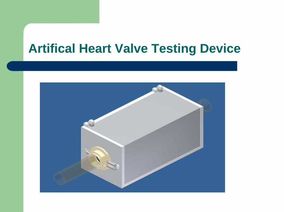
The housing for the device is made of aluminum and the biocompatible tubing enters from both sides connecting at the valveThe valve integration system includes a small door that pinches the valve to be tested in line with the tubing

Artifical Heart Valve Testing Device
The valve door pinches the valve to the housing with a rubber seal to maintain pressure during testing. The system is locked in place using a locking arm and the rigid connections shown.

Artifical Heart Valve Testing Device
The biocompatible tubing connects to the valve door shown previously. It also enters through the opposite side of the housing and attaches to a fitting just afterthe valve to be tested.The tubing passes through the Orsense sensor inside the device housing

Artifical Heart Valve Testing Device
The heating coil is shown below. It is located below the tubing between the valve and the sensor and is intended to maintain a homeostatic ambient temperature within the device.

Heating Coil
The heating coil is to be made from nichrome With a pre-defined voltage to activate the coil at 7.5 Volts, and a known current of 20mA, this allows for the resistance to be found via Ohm’s law, and the resistance is defined by the thickness of the coil. V=I/R –Ohm’s Law

Device Animation
See video file

Device Operation- Programming
Necessary equipment and software– FlashPIC development board with PIC16F877
microcontroller– CCS ICD-S programmer– C programming– MPLab IDE– LM35CZ (temperature sensor)– 9V battery

PIC Development Board
This board comes equipped with an analog to digital converter which will be utilized in temperature measuring.The board also contains the PIC16F877 microcontroller.An LCD screen is on the board for displaying digital information.A serial binary data connection is supplied in the form of RS-232.

FlashPIC Development Board
*Note* this development boardimage is missing the
LCD screen the wouldbe present on the
board used for this project.
http://www.pages.drexel.edu/~cy56/PIC.htm

PIC16F877 microcontroller
Most complex unit on the Flash board.Block Diagram Pin Diagram
http://www.pages.drexel.edu/~cy56/PIC.htmhttp://www.pages.drexel.edu/~cy56/PIC.htm

ICD-S Programmer and Debugger
Hardware/Firmware that burns .hex files to microchip PIC. Communicated to the chip through standard phone jack and to PC through RS-232 serial port
http://www.pages.drexel.edu/~cy56/PIC.htm

Temperature Sensor
LM35– Outputs its reading in analog signals– Range of ADC on development board is 0 to 5V
with 10 bit conversion, so resolution is 1023– Thus formula for analog to digitalconversion is Temperature in Celsius = 5.00 * Voltage from LM35 * 100.00/1023.00
http://www.facstaff.bucknell.edu/mastascu/elessonshtml/Sensors/LM35Ckt.jpg

Temperature Control System
Block Diagram
Edited from http://www.pages.drexel.edu/~cy56/PIC.htm

Temperature control system
Schematic with PIC16F877
http://2.bp.blogspot.com/_Se0VANaI9uM/R1QHMxSkrXI/AAAAAAAAAFk/VgKErYJKp5s/s1600-R/tempearure%2Bcontroller.jpg

Multisim Diagram
Temperature control system
*Note*- When trying to make multisimdiagram many parts are missing
including the PIC16F877 microcontroller .This is the best representation of imageIn previous slide

PCB Diagram
Temperature control system
*Note*- When trying to make multisimdiagram many parts are missing
including the PIC16F877 microcontroller . Thus the PCB diagram isnot as accurate as desired.

Digital Circuit Multisim
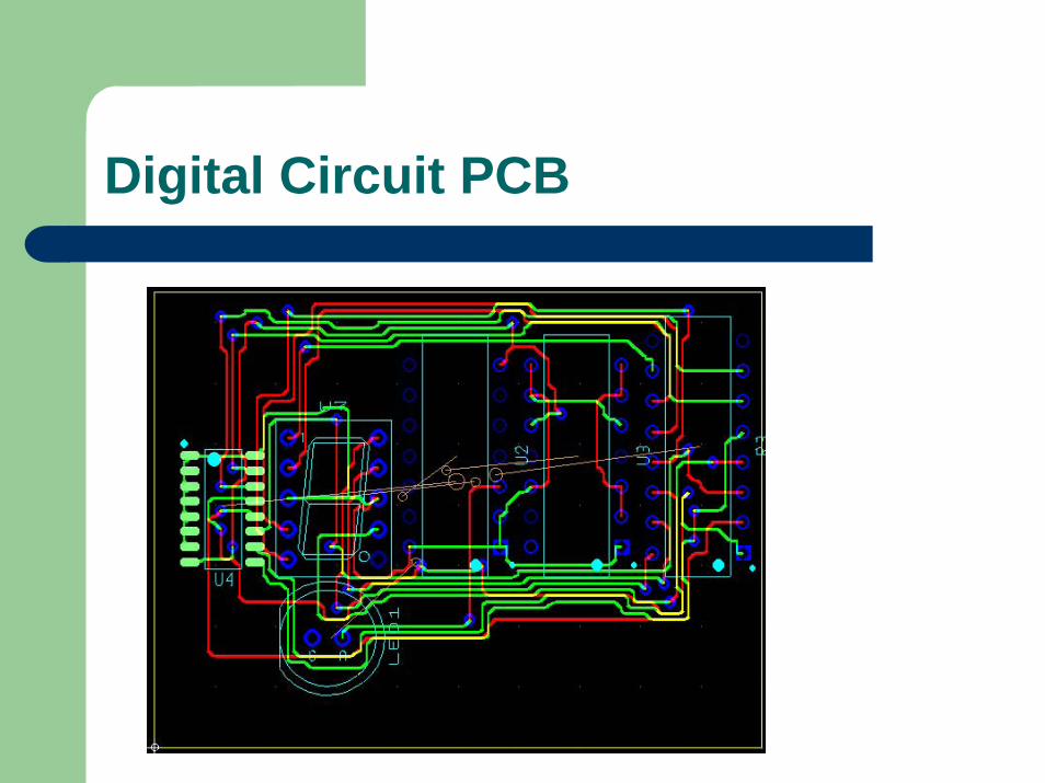
Digital Circuit PCB

Flow Rate
As mentioned before the flow rate will be measured by the Bio-probe Flow Transducer.When the Bioconsole 560 system is coupled with the Transducer the measurements are accurate to within +/- 5% of the flow rate. The transducers’ signals are output in digital therefore no ADC conversion is necessary and the signals can be read by the program and microcontroller readily.

Program Code
The program code is too lengthy for the powerpoint slides and can be found on the teams website. Within the code is a comparator function which will activate the heating coil if the temperature goes below a certain minimum pre-defined earlier in the code. Once the temperature goes above the goal it is then turned off from the same comparator function

Program Code
The flow rate is changed via the pump and therefore the transducers signals are just read from channel 2 and displayed when called upon. This flow rate is different that the pumps flow rate because the tranducer location is at the valve where the flow rate value is desired.Also in the code is the LCD function which calls upon the C program (LCD) to write the desired data to the LCD screen.

Summary
Variable flow rate is controlled by Medtronic’s blood pump and speed controller and displayed at the location of the pump. The flow rate at the valve is measured with the transducer.Artificial valve can be inserted into sealed door.Clotting factor’s are measured using Orsense’sNBM-200MP which uses Occlusion Spectroscopy to measure free hemoglobin levels.The NBM-200MP has its own displays to show the measured hemoglobin.

Summary
The pump made by Medtronic is for closed loop systems and minimizes the stress of RBC’s.The turbulence measuring device is able to measure clotting and work with actual blood with the biocompatible tubing selected. Homeostasis is maintained by monitoring and controlling the temperature, pressure, and flow rate of the closed system.

References
http://2.bp.blogspot.com/_Se0VANaI9uM/R1QHMxSkrXI/AAAAAAAAAFk/VgKErYJKp5s/s1600-R/tempearure%2Bcontroller.jpghttp://www.pages.drexel.edu/~cy56/PIC.htmhttp://www.medtronic.com/cardsurgery/arrested_heart/centrifugal_pump.htmlhttp://www.national.com/mpf/LM/LM35.html#Datasheethttp://www.orsense.com/Products