artificial antiphase boundary at the interface of ferrimagnetic spinel bilayers
TRANSCRIPT
Artificial antiphase boundary at the interface of ferrimagnetic spinel bilayers
Ana V. Ramos,1 Sylvia Matzen,1 Jean-Baptiste Moussy,1 Frédéric Ott,2 and Michel Viret31CEA-Saclay, IRAMIS, SPCSI, 91191 Gif-Sur-Yvette, France
2CEA-Saclay, IRAMIS, LLB, 91191 Gif-Sur-Yvette, France3CEA-Saclay, IRAMIS, SPEC, 91191 Gif-Sur-Yvette, France
�Received 24 July 2008; revised manuscript received 12 October 2008; published 5 January 2009�
CoFe2O4 /Fe3O4 bilayers represent an unusual exchange-coupled system whose properties are due to thenature of the oxide-oxide superexchange interactions at the interface. In this work, we analyze the magnetiza-tion reversal behavior and magnetic interface structure using a variety of advanced techniques. Low-temperature magnetization, magnetotransport, and polarized neutron reflectivity measurements suggest that themagnetization configuration at the bilayer interface mimics that of an antiphase boundary found in spinel ferritethin films, thus explaining the unique nature of the magnetic behavior.
DOI: 10.1103/PhysRevB.79.014401 PACS number�s�: 75.70.Cn, 75.60.Jk, 75.10.Pq, 61.05.fj
I. INTRODUCTION
The spinel ferrites have become of great interest to themagnetism community due to their potential applications inspintronic devices. In particular, this family of complex mag-netic oxides has been considered for magnetically hardblocking layers,1,2 half-metallic electrodes,3,4 and most re-cently for high-temperature spin filters.5,6 Another widelystudied topic, particularly in the case of Fe3O4, is the effectof antiphase boundaries �APBs� on the magnetic7,8 andmagnetotransport9–12 properties. In the present work, westudy the magnetic behavior of a particular CoFe2O4 /Fe3O4bilayer system which could potentially be used in fully epi-taxial oxide spin-filter magnetic tunnel junctions �MTJs�.CoFe2O4 is the magnetic tunnel barrier �or spin filter� andFe3O4 is the magnetic electrode.
This work comes as the sequel to a previous study involv-ing this particular system, in which it was determined that aunique exchange coupling interaction exists between the twoferrimagnets when the thickness of the CoFe2O4 layer is re-duced to a few nanometers.13 Similar exchange interactionshave recently been observed in other spinel-spinel bilayersystems.14 More precisely, we showed that inCoFe2O4�5 nm� /Fe3O4�15 nm� bilayers, the magnetizationreversal occurs in two steps. The CoFe2O4 layer reverses firstat a magnetic field slightly lower than its usual coercivity,followed by Fe3O4 at a magnetic field nearly ten timesgreater than its intrinsic coercive field. This suggests thatthere exists a strong exchange interaction between these twolayers that is stable in the antiparallel �AP� state—that is,after CoFe2O4 has switched. Because of the high Curie tem-peratures of CoFe2O4 and Fe3O4 �near 800 K for both�, thebilayers correspond to a ferromagnetic-ferromagnetic �FM-FM� exchange-coupled system in all measurements per-formed at room temperature and below. The goal of thispaper is to analyze the nature of the exchange couplingthrough a series of magnetic and magnetotransport experi-ments in order to shed light on the nature of the local mag-netic configuration at the interface of this unique system.
II. EXPERIMENT
The samples used in the present study were preparedby oxygen plasma-assisted molecular-beam epitaxy �MBE�,
as described in Ref. 13. BothAl2O3 / /CoFe2O4�5 nm� /Fe3O4�15 nm� andAl2O3 / /Fe3O4�15 nm� /CoFe2O4�5 nm� samples weregrown on �-Al2O3�0001� substrates, leading to the growth of�111�-oriented spinel films. Their structural and chemicalproperties were carefully analyzed by a number of standardcharacterization techniques in order to confirm the composi-tion and fully epitaxial nature of the two layers. Again, thedetails of the characterization may be found in Ref. 13.
Magnetic measurements of our CoFe2O4 /Fe3O4 bilayerswere performed using a vibrating sample magnetometer�VSM� equipped with a cryostat allowing to measure fromroom temperature down to liquid-helium temperature. Bothin-plane and out-of-plane hysteresis loops were measured,revealing a magnetic easy axis in the plane of the films, asexpected due to shape anisotropy. The current-in-plane �CIP�magnetotransport characteristics were studied in a QuantumDesign physical properties measurement system �PPMS� in amagnetic field of up to �7 T. These measurements wereperformed in the standard four-terminal geometry. Finally,polarized neutron reflectometry �PNR� experiments wereperformed at the Laboratoire Léon Brillouin facility usingpolarized neutrons of wavelength �=4.3 Å. Spin-up andspin-down �R++ and R−−� specular reflectivity curves wereobtained using the PRISM instrument and these were simu-lated using least-squares fits with the help of the SIMUL-
REFLEC program.15
III. RESULTS
A. Low-temperature magnetic properties
The original motivation behind the magnetic characteriza-tion of the CoFe2O4�5 nm� /Fe3O4�15 nm� combination wasto see if it was possible to obtain an antiparallel magneticstate between the two layers directly in contact with eachother, which in turn would permit future tunneling magne-toresistance experiments in Me /CoFe2O4 /Fe3O4-type MTJs,where Me is a nonmagnetic metallic electrode. These par-ticular thicknesses were chosen for two main reasons. First,they are representative of the thicknesses needed for a tunnelbarrier/electrode combination. Second, the magnetic proper-
PHYSICAL REVIEW B 79, 014401 �2009�
1098-0121/2009/79�1�/014401�8� ©2009 The American Physical Society014401-1
ties of this bilayer system are completely different when thethickness of CoFe2O4 is reduced to a few nanometers. WhileCoFe2O4 /Fe3O4 exchange-coupled systems containing a“thick” �i.e., �10 nm� CoFe2O4 layer have been alreadystudied and reveal typical exchange spring magnet behaviorwith CoFe2O4 playing the role of the hard ferromagnet,1,16
none to our knowledge addresses the ultrathin case. Becausethe coercive field of ultrathin CoFe2O4 films is dramaticallyreduced with respect to thicker films due to the increasedpresence of antiphase boundaries, we can expect a com-pletely different behavior in this particular system. Our pre-vious magnetization measurements at room temperature re-vealed magnetization loops displaying two inflection pointsaround 100–160 and 1800–3000 Oe. From now on, thesewill be labeled Hs1 and Hs2, respectively. Analysis of themagnetization height ratio indicates that CoFe2O4�5 nm� isthe first layer to switch �Hs1�.13 The second inflection point�Hs2� therefore corresponds to the switching of the Fe3O4electrode. The virgin in-plane magnetization curves mimicthe in-plane hysteresis loop, exhibiting two steps at Hs1 andHs2 which correspond to the switching of CoFe2O4 andFe3O4, respectively. Finally, it is worth noting that the out-of-plane magnetization curves show hysteresis while neverreaching the saturation value of the in-plane curve. This be-havior is typical of both CoFe2O4 and Fe3O4 single layersand cannot therefore be associated to the exchange couplingbetween the two.
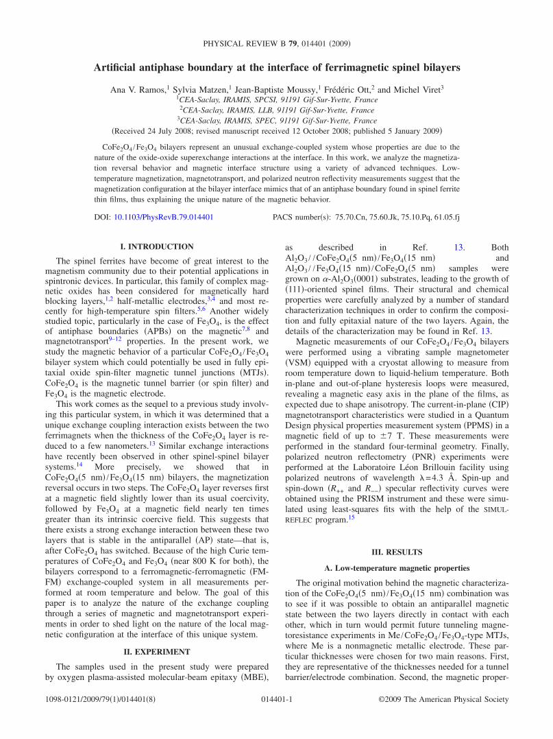
In order to further analyze the switching behavior origi-nally observed in our CoFe2O4 /Fe3O4 bilayers, we measuredthe in-plane magnetization at various temperatures from 300down to 5 K. The superposition of the magnetization curvesis shown in Fig. 1. We observe a systematic accentuation ofthe two-step magnetization loop with decreasing tempera-ture, with Hs2 reaching values as high as 1.2 T at 5 K. Hs1, onthe other hand, remains nearly unchanged. This suggests thatthe exchange coupling at the interface is so strong that itprevents the coercivity of CoFe2O4 from increasing with de-creasing temperature, as is commonly observed in uncoupledCoFe2O4 single layers.17,18 The exchange coupling musttherefore favor the early switching of the CoFe2O4 layer. Not
only do the low-temperature VSM measurements reinforcethe notion that an antiparallel magnetic state is present, butthey also reveal the remarkable strength of the exchange in-teraction at the CoFe2O4 /Fe3O4 interface.
Taking a closer look at the temperature dependence of theCoFe2O4�5 nm� /Fe3O4�15 nm� M�H� curves, we find thatHs2 varies linearly with temperature �T� �see the inset of Fig.1�. This evolution is stronger than that observed in bothCoFe2O4 and Fe3O4 single films, thus proving that its origindoes not lie in the intrinsic magnetic properties of one of thetwo layers. Because Hs2 is related to the magnetic energy ofthe Fe3O4 layer, this means that the sum of the other mag-netic energies also displays a linear temperature dependence.These contributions are the magnetocrystalline anisotropies�KCoFe2O4
and KFe3O4�, which are intrinsic to each film, and
the exchange energy �Eex� localized at the CoFe2O4 /Fe3O4interface. It has been shown that KFe3O4
changes very littlewith decreasing T and only increases at the Verweytransition,19 which is absent in our films. KCoFe2O4
, on theother hand, has been shown to increased markedly with de-creasing T.17 This suggests that KFe3O4
, although by all meanspresent, plays a much smaller role than KCoFe2O4
in the ob-served Hs2 dependence, leaving KCoFe2O4
and Eex to be theprincipal driving forces. Further theoretical studies would bevery useful to clarify the individual contributions of KCoFe2O4and Eex in the linear evolution of Hs2�T�.
The shape of the room-temperature and low-temperatureM�H� curves suggests that as the magnetic field is loweredfrom the saturated and “parallel” �P� state past zero field, theCoFe2O4 layer switches quite readily. Once in the “antipar-allel” state, a strong exchange field between CoFe2O4 andFe3O4 stabilizes the system in this configuration, making itextremely difficult for Fe3O4 to switch. What is most uniquein this system is therefore that the energetically stable or“blocked state” occurs after CoFe2O4 has switched, which israre in exchange-coupled systems involving two ferromag-netic or ferrimagnetic layers. Furthermore, the intrinsic coer-civities of the CoFe2O4�5 nm� and Fe3O4�15 nm� filmsalone �on the order of 200–300 Oe for both� are so close thatit is impossible to predict which of the two layers should actas the “hard” and “soft” ferromagnets. Only when the twoare put directly in contact with each other does it finallybecome clear that CoFe2O4 acts as the blocking layer after itsown magnetic reversal.
Low-temperature VSM measurements were similarly per-formed on Fe3O4�15 nm� /CoFe2O4�5 nm� samples with in-verse stacking order. The low-temperature magnetizationcurves and Hs2 evolution were comparable to those of theCoFe2O4�5 nm� /Fe3O4�15 nm� system, confirming that themagnetic behavior of this system is intrinsic to theCoFe2O4 /Fe3O4 interface, regardless of the stacking order.
B. In-plane magnetoresistance measurements
Another method to study the magnetic order �or disorder�in our CoFe2O4�5 nm� /Fe3O4�15 nm� bilayer samples wasto perform CIP transport measurements. This was done bydirectly placing electrical contacts on the top Fe3O4 layer formeasurements in the four terminal configurations. Since the
FIG. 1. �Color online� Magnetization curves for aCoFe2O4�5 nm� /Fe3O4�15 nm� bilayer measured at various tem-peratures. The normalized hysteresis loops are superposed and re-veal a linear evolution of Hs2 as a function of temperature �inset�.
RAMOS et al. PHYSICAL REVIEW B 79, 014401 �2009�
014401-2
resistivity difference between a 5 nm CoFe2O4 layer and a 15nm Fe3O4 film12 is of the order of 103, we can safely assumethat all the current flows in the Fe3O4 layer.
The electronic transport in Fe3O4 is governed by the FMdouble exchange interaction between Fe2+ and Fe3+ cations,which in turn permits electron hopping and thus conduction.When this FM double exchange is disturbed by the presenceof defects or other magnetic interactions, the resistance ver-sus applied magnetic-field �R�H�� curves in Fe3O4 exhibitsignificant magnetoresistance �MR�. Measuring the MR inFe3O4 thin films therefore directly probes the level of mag-netic disorder, which in the case of our CoFe2O4 /Fe3O4 sys-tem could be influenced by the exchange interactions at thebilayer interface.
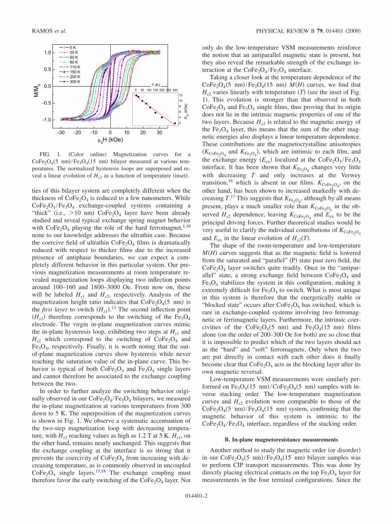
One very important point to note about Fe3O4 thin films isthat these exhibit an intrinsic MR due to the magnetic disor-der caused by the presence of APBs.9–12 The intrinsic MR at300 K for a Fe3O4�15 nm� single layer grown in our MBEchamber under similar conditions to our CoFe2O4 /Fe3O4 bi-layers is shown in red �circles� in Fig. 2�a�. In blue �tri-angles� and in gray �squares� are the MR curves for aCoFe2O4�5 nm� /Fe3O4�15 nm� bilayer measured at 300and 150 K, respectively. From these measurements it is quiteclear that the MR in Fe3O4 is dramatically modified in thebilayer case, indicating that an additional magnetic disorderis created by the interface with CoFe2O4. In other words, theexchange coupling between CoFe2O4 and Fe3O4 must resultin a local magnetic configuration at the interface that signifi-cantly disturbs the FM interactions in Fe3O4.
To better interpret the dynamics of magnetic switchingbehavior, we compared the derivatives of the R�H� andM�H� curves at 150 K. In the case of M�H�, the derivativedM /dH exhibits two clear peaks naturally corresponding tothe switching events Hs1 and Hs2. On the other hand, thederivative of R�H� contains only one peak which aligns per-fectly with that of Hs2 in dM /dH �see Fig. 2�b��. This simple
analysis confirms that Fe3O4 is the second layer to switch, aswas originally deduced from the magnetization height ratioin the M�H� measurements.13
The dR /dH characteristics therefore tell us that as theapplied magnetic field is lowered from saturation, past theswitching of the CoFe2O4 layer, the magnetic configurationthroughout the entire Fe3O4 film does not change signifi-cantly. This may be seen by the lack of any noticeable peakin dR /dH from H=20 kOe down to H=Hs2. Only when Hbecomes great enough to overcome Eex is Fe3O4 finally re-leased from the blocked configuration, switching rapidly torealign with the direction of the applied magnetic field. Wenote that the noise in dR /dH around −5 kOe��0H�5 kOe is due to a change in the step size in the R�H�measurements and did not result in any reproducible peaks inmultiple measurements.
C. Polarized neutron reflectivity
PNR is an extremely valuable tool for the character-ization of magnetic multilayers with complex exchangeinteractions. In the study of our�-Al2O3 / /CoFe2O4�5 nm� /Fe3O4�15 nm� and�-Al2O3 / /Fe3O4�15 nm� /CoFe2O4�5 nm� bilayer systems,PNR provided a complementary analysis of the magneticreversal behavior to the VSM and PPMS measurements, inparticular thanks to its ability to extract magnetization depthprofiles across the thickness of the films and at different ap-plied magnetic fields. As was the case with VSM, both stack-ing orders yielded similar results, again proving that the ex-change interaction at the interface was independent ofstacking order. For the purposes of this paper, we will there-fore focus on the results for the �-Al2O3 / /CoFe2O4 /Fe3O4stacking order only. Following the acquisition of the reflec-tivity curves, these were fitted by a model that took intoconsideration the following fitting parameters for each of the
(a) (b)
FIG. 2. �Color online� Current-in-plane magnetotransport measurements in a CoFe2O4�5 nm� /Fe3O4�15 nm� bilayer. �a� Magnetoresis-tance measurements in the CoFe2O4 /Fe3O4 sample at 300 and at 150 K. The MR curve for a Fe3O4 �15 nm� single layer is also shown at300 K as a reference. �b� Comparison of the derivatives of the magnetization and magnetoresistance curves in aCoFe2O4�5 nm� /Fe3O4�15 nm� sample at 150 K. dR /dH exhibits one single peak �symmetric for �H� which aligns perfectly with Hs2 ofdM /dH—that is, with the switching of Fe3O4.
ARTIFICIAL ANTIPHASE BOUNDARY AT THE… PHYSICAL REVIEW B 79, 014401 �2009�
014401-3
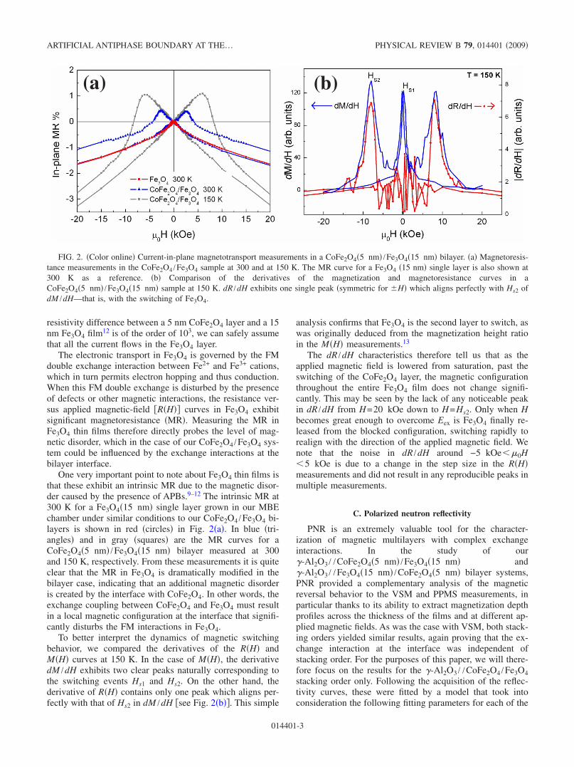
sample constituents: film thickness �t�, material density �� inunit cells/m3�, neutron-scattering length �b in fm/unit cell�,magnetic moment ���, and roughness ��. � were fixed at1.361028 unit cells /m3 for Fe3O4 and 1.351028 unit cells /m3 for CoFe2O4 and fixed at 0.3 nm forthe all of the layers based on x-ray reflectivity measurements.The total thickness of the CoFe2O4 /Fe3O4 bilayer was fixedat 24�1 nm based on x-ray reflectivity measurements aswell �see Fig. 3�a��. The x-ray reflectivity measurements sys-tematically yielded a thickness slightly higher than the aimed20 nm. The theoretical values for b in CoFe2O4 and Fe3O4
�44.6 and 51.6 fm, respectively� were used as a guideline forthe fits.
PNR measurements on a CoFe2O4�5 nm� /Fe3O4�15 nm�bilayer deposited directly on �-Al2O3 began at the maximumapplied magnetic field allowed by the magnet in the neutronspectrometer, which was 1.2 T. At the room-temperaturemagnetization curve of this sample being closed �i.e., revers-ible� at 1.2 T, we could assume that our bilayer system wassaturated and in the parallel magnetic state. The reflectivitycurve and simulation parameters for theCoFe2O4�5 nm� /Fe3O4�15 nm� bilayer at H= +1.2 T and
(b) (c)
(a)
FIG. 3. �Color online� Room-temperature PNR curves for a CoFe2O4�5 nm� /Fe3O4�15 nm� bilayer at �a� +1.2 T and �b� +0.05 T�coming from negative field H=−1.2 T�. The tables below each graph show the fitting parameters used to model the experimental curves andthus extract information about the magnetic configuration in the films. The error bar in the measurement of � is �0.1�B.
RAMOS et al. PHYSICAL REVIEW B 79, 014401 �2009�
014401-4
T=300 K are shown in Fig. 3�b�. In this figure we see thatwe are able to reproduce the experimental R++ and R−− re-flectivity curves using a bilayer model in which t, b, and � ofthe CoFe2O4 and Fe3O4 layers correspond well with thoseexpected for 5 and 15 nm films of each material, respec-tively. This simple PNR measurement confirms the bilayernature of the sample via a magnetic rather than structural orchemical characterization technique.
In the next experiment, we swept the field from H=−1.2 T, past the first switching event at Hs1, to H=+0.05 T. The experimental reflectivity curve obtained at thenew field of 0.05 T is shown in Fig. 3�c�. This second mea-surement was only reproducible using a model that containeda magnetization parallel to the applied field for a portion ofthe CoFe2O4 layer, whereas for Fe3O4, the magnetizationremained antiparallel to the field. We note that when fittingall of the reflectivity curves at intermediate magnetic fields,the total thickness of the bilayer was fixed to that originallyfound for the measurement at 1.2 T. This important resultconfirms the presence of an antiparallel magnetic state for agiven magnetic field between Hs1 and Hs2, while also prov-ing that the CoFe2O4 film is indeed the first to reverse itsmagnetization. The negatively magnetized portion of the bi-layer had to be broken down into two sublayers of 5.5 and18.2 nm, the first having a reduced magnetic moment withrespect to the second, whereas the thickness of the reversedCoFe2O4 layer was determined to be 1.9 nm, thinner than theexpected 5 nm. We believe that the second 5.5 nm layercorresponds to an intermediate zone at the CoFe2O4 /Fe3O4interface that actually includes some of both materials. Thereduced moment in this interfacial zone could be explainedby the averaged moments of the positive CoFe2O4 and nega-tive Fe3O4 contributions, as well as by a possible progressiveswitching of the spins on either side of the interface due to amore complicated local magnetic configuration.
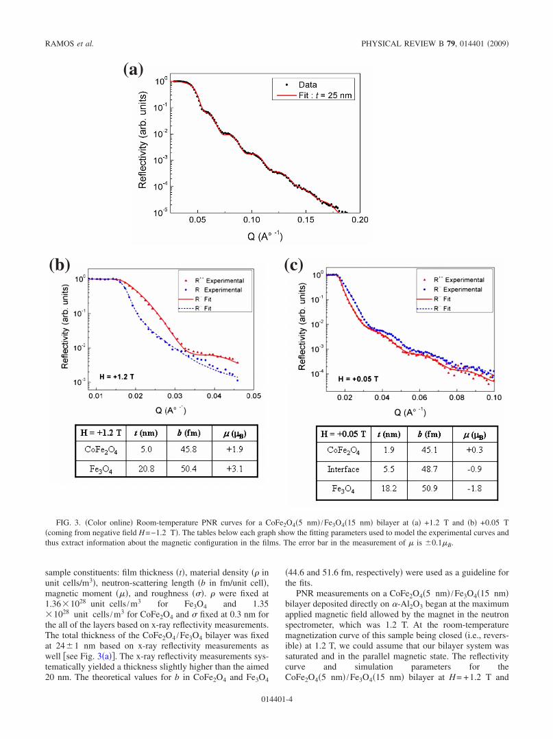
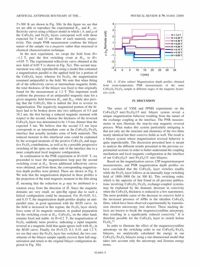
In continuation to the PNR experiment at H=0.05 T, weproceeded to trace the magnetization loop past the secondswitching event at Hs2. Seven additional reflectivity curveswere obtained, and from them, the corresponding magnetiza-tion depth profiles were plotted. These are shown in Fig. 4.We note that the magnetization depicted in these profiles isthe projection of the total magnetic moment in the film along
H� , meaning that the reduction in � may be attributed to a
rotation away from the direction of H� . Since the magneticdomains are very small, no spin-flip signal due to such ahelical configuration could be measured. For H=0.05, 0.1,and 0.15 T, the magnetization depth profiles display an anti-parallel state, in good agreement with the M�H� curve. Asthe field is increased in this regime, the Fe3O4 layer slowlyloses some of its magnetic moment, in gradual preparationfor the switching event at Hs2. CoFe2O4, on the other hand,remains fixed and stable. At H=0.2 T, the magnetization ofFe3O4 suddenly turns positive, indicating a rapid magneticreversal at a magnetic field that again agrees well with Hs2 inthe M�H� curve. Finally, for H=0.25, 0.3, 0.35, and 1.2 T,we see that once the Fe3O4 layer has switched, the two con-stituents of the bilayer sample rapidly recover their full mag-netization and return to the original bilayer configuration de-picted in Fig. 3�b�.
IV. DISCUSSION
The series of VSM and PPMS experiments on theCoFe2O4�5 nm� /Fe3O4�15 nm� bilayer system reveal aunique magnetization behavior resulting from the nature ofthe exchange coupling at the interface. The PNR measure-ments in turn illustrate the step-by-step magnetic reversalprocess. What makes this system particularly intriguing isthat not only are the structure and chemistry of the two filmsnearly identical but their coercive fields as well. The result isa bilayer system whose magnetization reversal behavior isquite unpredictable. The discussion presented here is meantto analyze the different results presented in the previous ex-perimental sections in order to better understand the couplingmechanism and local magnetic configuration at the interfaceof our CoFe2O4�5 nm� /Fe3O4�15 nm� bilayers.
Based on the magnetization curves, CIP magnetotransportmeasurements, and PNR magnetization depth profiles wehave concluded that the CoFe2O4 layer switches readilywhile the Fe3O4 layer follows at an unusually large switchingfield of 1800–3000 Oe �at 300 K�. This switching order,which is the opposite of that found in all previous publica-tions involving CoFe2O4 /Fe3O4 exchange-coupled systems,may be explained by the dramatic decrease in coercivitywhen the CoFe2O4 thickness is reduced to a few nanometers.The most probable cause of the decrease in coercive field isthe increased presence of APBs in the ultrathin CoFe2O4films, which have been observed experimentally by transmis-sion electron microscopy �not shown�. These stacking de-fects are known to break the magnetocrystalline anisotropy,thus resulting in a significantly reduced coercivity.7 It istherefore possible for the CoFe2O4 layer to switch beforeFe3O4.13
In order to illustrate the effect of the magnetocrystallineanisotropy on the switching order in our CoFe2O4 /Fe3O4bilayers, we analytically calculated the energy in ourCoFe2O4 /Fe3O4 bilayers using a one-dimensional model thattakes into account only the anisotropy and Zeeman energyterms,
FIG. 4. �Color online� Magnetization depth profiles obtainedfrom room-temperature PNR measurements of the sameCoFe2O4 /Fe3O4 sample at different stages of the magnetic hyster-esis cycle.
ARTIFICIAL ANTIPHASE BOUNDARY AT THE… PHYSICAL REVIEW B 79, 014401 �2009�
014401-5
E = �K1 sin2 �1 − HM1 cos �1�t1
+ �K2 sin2 �2 − HM2 cos �2�t2, �1�
where K is the anisotropy constant, � is the angle betweenthe magnetization and the applied magnetic field, and t is thefilm thickness. Here layer 1 is the CoFe2O4 and layer 2 isFe3O4. For the purposes of this calculation, we assumed thatM1=M2=350 kA /m and that t1= t2=15 nm in order toeliminate the effect of the magnetic mass on the reversalbehavior. The decrease in CoFe2O4 thickness was thereforerepresented by a decrease in K1, corresponding to the de-crease in magnetocrystalline anisotropy caused by APBs. K2was held constant at 1.3104 J /m3, which corresponds tothe bulk value in Fe3O4.19 The high K1 value for CoFe2O4was taken to be 1105 J /m3, which is close to the bulkvalue.20 Finally K1 and K2 are assumed to be in the plane ofthe film and parallel to H.
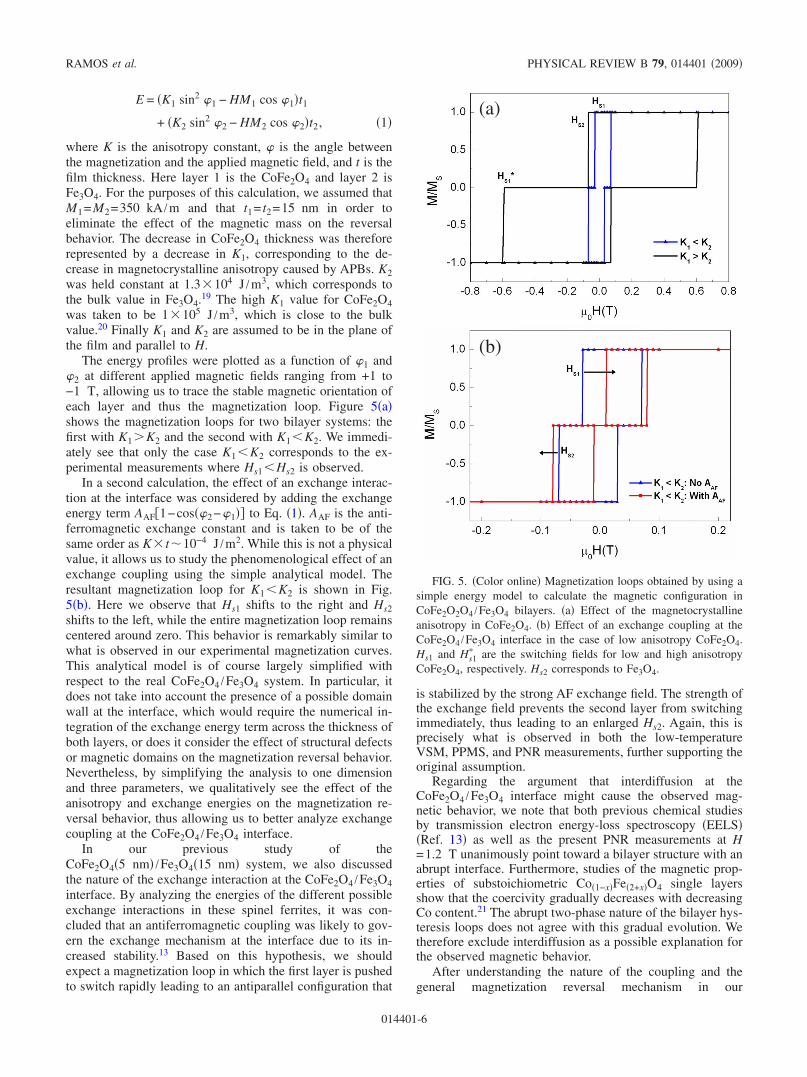
The energy profiles were plotted as a function of �1 and�2 at different applied magnetic fields ranging from +1 to−1 T, allowing us to trace the stable magnetic orientation ofeach layer and thus the magnetization loop. Figure 5�a�shows the magnetization loops for two bilayer systems: thefirst with K1�K2 and the second with K1�K2. We immedi-ately see that only the case K1�K2 corresponds to the ex-perimental measurements where Hs1�Hs2 is observed.
In a second calculation, the effect of an exchange interac-tion at the interface was considered by adding the exchangeenergy term AAF�1−cos��2−�1�� to Eq. �1�. AAF is the anti-ferromagnetic exchange constant and is taken to be of thesame order as K t�10−4 J /m2. While this is not a physicalvalue, it allows us to study the phenomenological effect of anexchange coupling using the simple analytical model. Theresultant magnetization loop for K1�K2 is shown in Fig.5�b�. Here we observe that Hs1 shifts to the right and Hs2shifts to the left, while the entire magnetization loop remainscentered around zero. This behavior is remarkably similar towhat is observed in our experimental magnetization curves.This analytical model is of course largely simplified withrespect to the real CoFe2O4 /Fe3O4 system. In particular, itdoes not take into account the presence of a possible domainwall at the interface, which would require the numerical in-tegration of the exchange energy term across the thickness ofboth layers, or does it consider the effect of structural defectsor magnetic domains on the magnetization reversal behavior.Nevertheless, by simplifying the analysis to one dimensionand three parameters, we qualitatively see the effect of theanisotropy and exchange energies on the magnetization re-versal behavior, thus allowing us to better analyze exchangecoupling at the CoFe2O4 /Fe3O4 interface.
In our previous study of theCoFe2O4�5 nm� /Fe3O4�15 nm� system, we also discussedthe nature of the exchange interaction at the CoFe2O4 /Fe3O4interface. By analyzing the energies of the different possibleexchange interactions in these spinel ferrites, it was con-cluded that an antiferromagnetic coupling was likely to gov-ern the exchange mechanism at the interface due to its in-creased stability.13 Based on this hypothesis, we shouldexpect a magnetization loop in which the first layer is pushedto switch rapidly leading to an antiparallel configuration that
is stabilized by the strong AF exchange field. The strength ofthe exchange field prevents the second layer from switchingimmediately, thus leading to an enlarged Hs2. Again, this isprecisely what is observed in both the low-temperatureVSM, PPMS, and PNR measurements, further supporting theoriginal assumption.
Regarding the argument that interdiffusion at theCoFe2O4 /Fe3O4 interface might cause the observed mag-netic behavior, we note that both previous chemical studiesby transmission electron energy-loss spectroscopy �EELS��Ref. 13� as well as the present PNR measurements at H=1.2 T unanimously point toward a bilayer structure with anabrupt interface. Furthermore, studies of the magnetic prop-erties of substoichiometric Co�1−x�Fe�2+x�O4 single layersshow that the coercivity gradually decreases with decreasingCo content.21 The abrupt two-phase nature of the bilayer hys-teresis loops does not agree with this gradual evolution. Wetherefore exclude interdiffusion as a possible explanation forthe observed magnetic behavior.
After understanding the nature of the coupling and thegeneral magnetization reversal mechanism in our
(a)
(b)
FIG. 5. �Color online� Magnetization loops obtained by using asimple energy model to calculate the magnetic configuration inCoFe2O2O4 /Fe3O4 bilayers. �a� Effect of the magnetocrystallineanisotropy in CoFe2O4. �b� Effect of an exchange coupling at theCoFe2O4 /Fe3O4 interface in the case of low anisotropy CoFe2O4.Hs1 and Hs1
� are the switching fields for low and high anisotropyCoFe2O4, respectively. Hs2 corresponds to Fe3O4.
RAMOS et al. PHYSICAL REVIEW B 79, 014401 �2009�
014401-6
CoFe2O4�5 nm� /Fe3O4�15 nm�, the next step is to definethe local magnetic configuration at the bilayer interface. Herethe interpretation becomes more delicate as none of the ex-perimental methods described above give direct access tothis information. To begin, we observe that there is a positiveslope in the magnetization curve with respect to the appliedfield in the range between Hs1 and Hs2 both at room tempera-ture and at low temperature �Fig. 1�. The positive slope isalso visible in the tail of CoFe2O4 minor loops previouslyshown in Ref. 13. This detail leads us to believe that a do-main wall is present at the interface for this field range. Infact, such a slope has been previously determined to corre-spond to the compression of an interfacial domain wallpresent in FM/FM exchanged-coupled interfaces.22 In thecase of our CoFe2O4�5 nm� /Fe3O4�15 nm� bilayers, thiswould suggest that there exists a progressive rotation of thespins, coupled antiferromagnetically on either side of the in-terface, toward a parallel or antiparallel alignment �depend-ing on the magnitude of the applied magnetic field� far fromthe interface.
The possibility of an interfacial region containing adomain-wall structure is further supported by the magnetiza-tion depth profiles in the PNR measurements. In Fig. 4, wesee that all of the profiles obtained in the AP configurationcontain an interfacial region of a few nanometers in thick-ness, covering part of CoFe2O4 and part of Fe3O4, with areduced magnetization with respect to Fe3O4. As was men-tioned earlier, this interfacial layer of the depth profile couldbe due to a progressive switching of the antiparallel momentsin CoFe2O4 toward the parallel moments in Fe3O4. The re-duced negative moment would therefore correspond to theaverage of the moments in both layers projected along thedirection of the applied field across the entire thickness ofthis interfacial domain wall. In order to better identify thestructure at the interface, the PNR curves could have beenfitted with a greater number of sublayers at theCoFe2O4 /Fe3O4 interface. However, doing so would intro-duce a significant number of additional variables into themodel and thus considerably reduce the reliability of the fits.We have therefore chosen to rely on the three sublayer modeldepicted in Fig. 4.
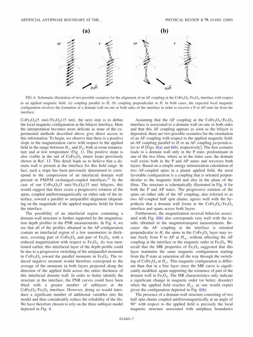
Assuming that the AF coupling at the CoFe2O4 /Fe3O4interface is associated to a domain wall on one or both sidesand that this AF coupling appears as soon as the bilayer isdeposited, there are two possible scenarios for the orientationof an AF coupling with respect to the applied magnetic field:an AF coupling parallel to H or an AF coupling perpendicu-lar to H �Figs. 6�a� and 6�b�, respectively�. The first scenarioleads to a domain wall only in the P state, predominant inone of the two films, where as in the latter case, the domainwall exists both in the P and AP states and traverses bothlayers. Based on a simple energy minimization calculation oftwo AF-coupled spins in a planar applied field, the mostfavorable configuration is a coupling that is oriented perpen-dicular to the magnetic field and also in the plane of thefilms. The structure is schematically illustrated in Fig. 6 forboth the P and AP states. The progressive rotation of thespins on either side of the AF coupling, also referred to astwo AF-coupled half spin chains, agrees well with the hy-pothesis that a domain wall forms at the CoFe2O4 /Fe3O4interface and spans across both layers.
Furthermore, the magnetization reversal behavior associ-ated with Fig. 6�b� also corresponds very well with the re-sults obtained in the magnetotransport measurements. Be-cause the AF coupling at the interface is orientedperpendicular to H, the spins in the CoFe2O4 layer may ro-tate freely from P to AP at Hs1, without affecting the AFcoupling at the interface or the magnetic order in Fe3O4. Werecall that the MR properties of Fe3O4 suggested that thislayer maintains the same magnetic configuration startingfrom the P state at saturation all the way through the switch-ing of CoFe2O4 at Hs1. This magnetic configuration is differ-ent than that in a free layer since the MR curve is signifi-cantly modified, again supporting the existence of part of thedomain wall in Fe3O4. The MR characteristics only indicatea significant change in magnetic order �or better, disorder�when the applied field reaches Hs2, as one would expectgiven the configuration depicted in Fig. 6�b�.
The presence of a domain-wall structure consisting of twohalf spin chains coupled antiferromagnetically at an angle of90° with respect to the applied field is precisely the localmagnetic structure associated with antiphase boundaries
(a) (b)
FIG. 6. Schematic illustration of two possible scenarios for the alignment of an AF coupling at the CoFe2O4 /Fe3O4 interface with respect
to an applied magnetic field: �a� coupling parallel to H� ; �b� coupling perpendicular to H� . In both cases, the expected local magneticconfiguration involves the formation of a domain wall on one or both sides of the interface in order to recover a P or AP state far from theinterface.
ARTIFICIAL ANTIPHASE BOUNDARY AT THE… PHYSICAL REVIEW B 79, 014401 �2009�
014401-7
commonly found in spinel ferrite films.7,11,12,23 In certainAPBs, the stacking fault generates an additional AF couplingthat is oriented perpendicular to the applied field. Far fromthe APB, the spins realign along H, and this is achieved viaa progressive rotation of the spins on either side of the APBtoward the P configuration, exactly as is shown in the Pscenario in Fig. 6�b�. In other words, the local magnetic con-figuration that we predict at the CoFe2O4 /Fe3O4 interfacewhen the bilayer system is in the P or saturated state is inessence an “artificial APB.” In the AP state, the configurationcorresponds to an APB in which the two half spin chainsrotate in opposite directions. We therefore believe that thestructural and magnetic defect generated by theCoFe2O4 /Fe3O4 interface is, in fact, equivalent to a specialtype of APB in which the two AF-coupled half spin chainsmay switch from P to AP depending on the magnitude anddirection of the external magnetic field.
It is important to mention that the local magnetic configu-ration proposed in this discussion is surely simplified withrespect to reality. In particular, we know that ourCoFe2O4�5 nm� /Fe3O4�15 nm� bilayers contain manysmall magnetic domains generated by the presence of APBsin the films. These domains, having a size on the order of100 nm, inevitably influence the overall switching behaviorin our system. The AF-coupled spin-chain configuration pro-posed above is therefore probably repeated from one domainto another, leading to a situation that is more complex thanthat described above. Whether or not these domains act in-dependently of each other is a question that for the momentremains unanswered. Also, we do not know to what extentthe boundary conditions imposed by the small domain sizeaffect the spin-chain configuration in each domain. Further
numerical simulations of a multidomain system in whicheach domain contains an artificial APB like that describedabove should improve the understanding of this complexproblem.
V. CONCLUSION
In conclusion, the magnetic switching behavior of fullyepitaxial CoFe2O4�5 nm� /Fe3O4�15 nm� bilayers has beenstudied using VSM, CIP magnetotransport measurements,and PNR. We have shown that by directly growing Fe3O4 onCoFe2O4 or vice versa, a two-phase magnetization loop maybe obtained without the insertion of a nonmagnetic spacer.This magnetization loop reveals a strong exchange couplinginteraction between the two layers that blocks the Fe3O4layer in the antiparallel state, after CoFe2O4 has switched.Careful analysis of the magnetic and magnetotransport mea-surements suggests that the local magnetic configuration atthe CoFe2O4 /Fe3O4 interface involves a domain-wall-typestructure containing two AF-coupled half spin chains, thusgenerating an artificial antiphase boundary. The unique mag-netic properties of this bilayer system therefore make it aninteresting candidate for future theoretical studies, as well asspin-polarized transport measurements in spin-filter MTJs.
ACKNOWLEDGMENTS
The authors would like to thank M. Gautier-Soyer for theuseful discussions. We are also very grateful to P. Bonvillefor the help with the low-temperature VSM experiments.This project was partially funded by the CNANO Île deFrance “FILASPIN” project.
1 Y. Suzuki, R. B. van Dover, E. M. Gyorgy, J. M. Phillips, and R.J. Felder, Phys. Rev. B 53, 14016 �1996�.
2 N. Viart, R. Sayed Hassam, C. Mény, P. Panissod, C. Ulhaq-Bouillet, J. L. Loison, G. Versini, F. Huber, and G. Pourroy,Appl. Phys. Lett. 86, 192514 �2005�.
3 P. Seneor, A. Fert, J.-L. Maurice, F. Petroff, and A. Vaures, Appl.Phys. Lett. 74, 4017 �1999�.
4 G. Hu and Y. Suzuki, Phys. Rev. Lett. 89, 276601 �2002�.5 U. Luders, M. Bibes, K. Bouzehouane, E. Jacquet, J.-P. Contour,
S. Fusil, J. Fontcuberta, A. Barthélémy, and A. Fert, Appl. Phys.Lett. 88, 082505 �2006�.
6 A. V. Ramos, M.-J. Guittet, J.-B. Moussy, R. Mattana, C. Der-anlot, F. Petroff, and C. Gatel, Appl. Phys. Lett. 91, 122107�2007�.
7 D. T. Margulies, F. T. Parker, M. L. Rudee, F. E. Spada, J. N.Chapman, P. R. Aitchison, and A. E. Berkowitz, Phys. Rev. Lett.79, 5162 �1997�.
8 J.-B. Moussy, S. Gota, A. Bataille, M.-J. Guittet, M. G. Soyer, F.Delille, B. Dieny, F. Ott, T. D. Doan et al., Phys. Rev. B 70,174448 �2004�.
9 J. M. D. Coey, A. E. Berkowitz, L. Balcells, F. F. Putris, and F.T. Parker, Appl. Phys. Lett. 72, 734 �1998�.
10 M. Ziese and H. J. Blythe, J. Phys.: Condens. Matter 12, 13�2000�.
11 W. Eerenstein, T. T. M. Palstra, S. S. Saxena, and T. Hibma,Phys. Rev. Lett. 88, 247204 �2002�.
12 A. V. Ramos, J. B. Moussy, M. J. Guittet, A. M. Bataille, M.Gautier-Soyer, M. Viret, C. Gatel, P. Bayle-Guillemaud, and E.Snoeck, J. Appl. Phys. 100, 103902 �2006�.
13 A. V. Ramos, J.-B. Moussy, M.-J. Guittet, M. Gautier-Soyer, C.Gatel, P. Bayle-Guillemaud, B. Warot-Fonrose, and E. Snoeck,Phys. Rev. B 75, 224421 �2007�.
14 B. B. Nelson-Cheeseman, R. V. Chopdekar, J. S. Bettinger, E.Arenholz, and Y. Suzuki, J. Appl. Phys. 103, 07B524 �2008�.
15 http://www llb.cea.fr/prism/programs/simulreflec/simulreflec.html
16 M. Ziese, R. Hohne, A. Bollero, H. C. Semmelhack, P. Es-quinazi, and K. Zimmer, Eur. Phys. J. B 45, 38054 �2005�.
17 L. Horng, G. Chern, M. C. Chen, P. C. Kang, and D. S. Lee, J.Magn. Magn. Mater. 270, 389 �2004�.
18 C. Gatel, Ph.D. thesis, INSA Toulouse, 2004.19 L. R. Bickford, Phys. Rev. 76, 137 �1949�.20 Y. Suzuki, G. Hu, R. B. van Dover, and R. J. Cava, J. Magn.
Magn. Mater. 191, 1 �1999�.21 A. V. Ramos �unpublished�.22 F. Canet, C. Bellouard, L. Joly, and S. Mangin, Phys. Rev. B 69,
094402 �2004�.23 H. Zijlstra, IEEE Trans. Magn. 15, 1246 �1979�.
RAMOS et al. PHYSICAL REVIEW B 79, 014401 �2009�
014401-8