artefact scanning using nextengine 3d scanner
TRANSCRIPT
2
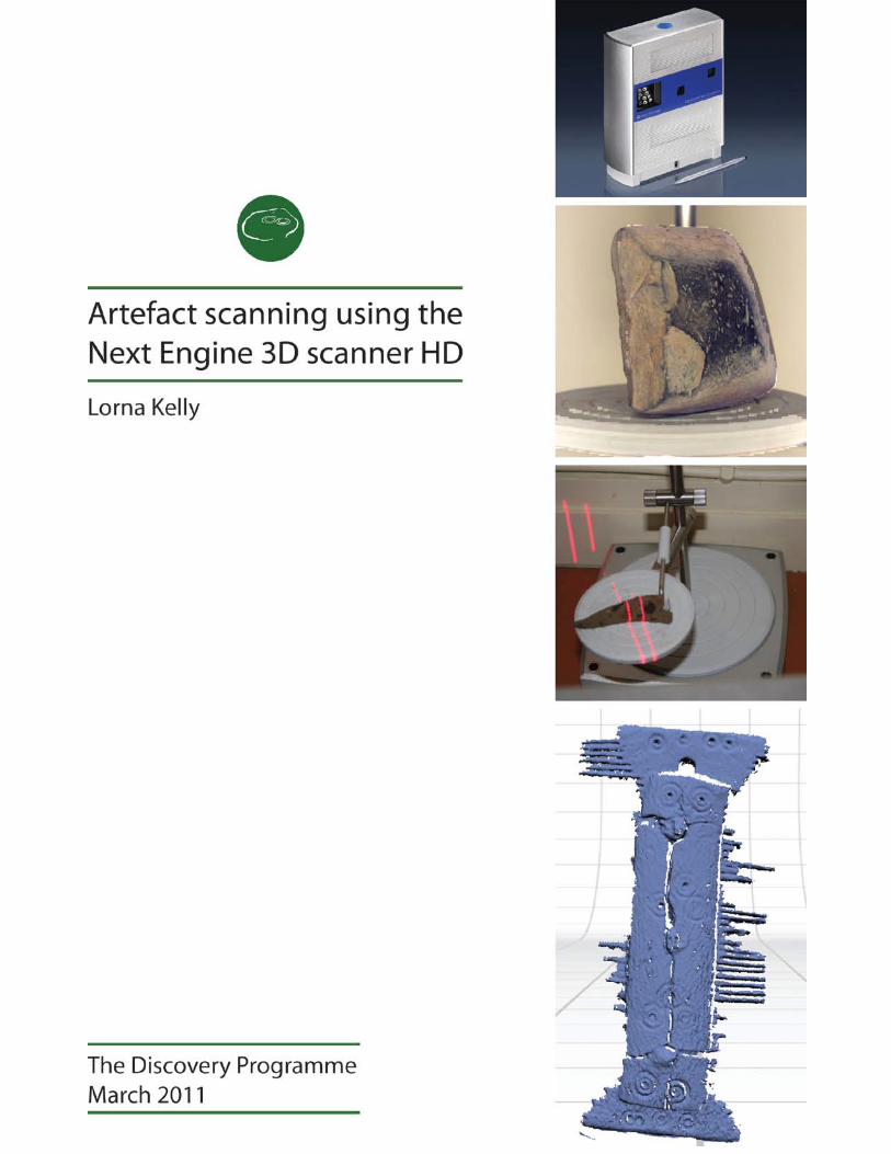
Artefact scanning using the Next Engine 3D scanner HD Lorna Kelly – The Discovery Programme.
Background 3D laser scanning has now become a commonly used, high tech approach to accurately obtaining real 3D data from the surface of an object. This has allowed laser scanning to become widely accepted in an array of applications such as industrial, civil surveying, architectural, reverse engineering and, as in the case of this project, heritage and archaeology.
Laser scanning as a term encompasses a broad range of instruments and techniques, operating over a wide range of scales including landscape recording using aerial sensors and ground based systems for capturing detail of buildings and excavations. These technologies have been extensively reported in a number of previously released Discovery Programme reports. This report focuses on the scanning experiments undertaken on a number of small scale objects - a selection of artefacts found during the Medieval Rural Settlement project excavation at Tulsk, Co Roscommon.
The objective of the 3D laser scanning test was to assess how successfully this technique could be applied to capture and record artefacts found during archaeological excavations, to an acceptable accuracy and precision. Technologies such as this are driving the adaption of interactive 3D representations. Visual superiority alongside long-term digital preservation of objects are just some advantages to this technology over current, less realistic, methods of archiving such data. Preserving by record, for archival or scaled 3D representations, allow fresh and professionally advanced methods of handling, viewing, and studying the data. However, these advantages are only going to materialise if the scanning can produce reliable results for a range of objects and artefacts
Instrumentation The Discovery Programme proposed to scan ten artefacts, using the Next Engine 3D scanner HD, for the purpose of 3D representation and also to assess the capabilities itself. NextEngine, Inc. is based in the USA and as such its instruments use imperial units of measurement i.e. inches. With accuracy of 0.005 inches and at a cost of less than 10 times than that of rivalling systems, it has the potential to give mathematically accurate representations of the artefacts being scanned at an affordable price. (Price March 2011, $2,995)
MACRO MODE WIDE MODE 3D Point Density 400 dpi 150 dpi Dimensional Accuracy +/- 0.005” +/- 0.015” Field of view 5.1” x 3.8” 13.5” x 10.1” Ideal Distance to Object Speed 50,000 50,000 Time per scan 2 min 2 min
3
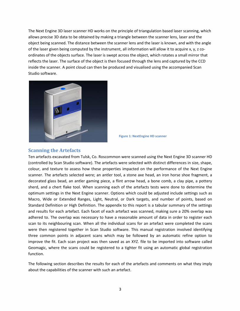
The Next Engine 3D laser scanner HD works on the principle of triangulation based laser scanning, which allows precise 3D data to be obtained by making a triangle between the scanner lens, laser and the object being scanned. The distance between the scanner lens and the laser is known, and with the angle of the laser given being computed by the instrument, all information will allow it to acquire x, y, z co-ordinates of the objects surface. The laser is swept across the object, which rotates a small mirror that reflects the laser. The surface of the object is then focused through the lens and captured by the CCD inside the scanner. A point cloud can then be produced and visualised using the accompanied Scan Studio software.
Scanning the Artefacts Ten artefacts excavated from Tulsk, Co. Roscommon were scanned using the Next Engine 3D scanner HD (controlled by Scan Studio software). The artefacts were selected with distinct differences in size, shape, colour, and texture to assess how these properties impacted on the performance of the Next Engine scanner. The artefacts selected were; an antler tool, a stone axe head, an iron horse shoe fragment, a decorated glass bead, an antler gaming piece, a flint arrow head, a bone comb, a clay pipe, a pottery sherd, and a chert flake tool. When scanning each of the artefacts tests were done to determine the optimum settings in the Next Engine scanner. Options which could be adjusted include settings such as Macro, Wide or Extended Ranges, Light, Neutral, or Dark targets, and number of points, based on Standard Definition or High Definition. The appendix to this report is a tabular summary of the settings and results for each artefact. Each facet of each artefact was scanned, making sure a 20% overlap was adhered to. The overlap was necessary to have a reasonable amount of data in order to register each scan to its neighbouring scan. When all the individual scans for an artefact were completed the scans were then registered together in Scan Studio software. This manual registration involved identifying three common points in adjacent scans which may be followed by an automatic refine option to improve the fit. Each scan project was then saved as an XYZ. file to be imported into software called Geomagic, where the scans could be registered to a tighter fit using an automatic global registration function.
The following section describes the results for each of the artefacts and comments on what they imply about the capabilities of the scanner with such an artefact.
Figure 1: NextEngine HD scanner
4
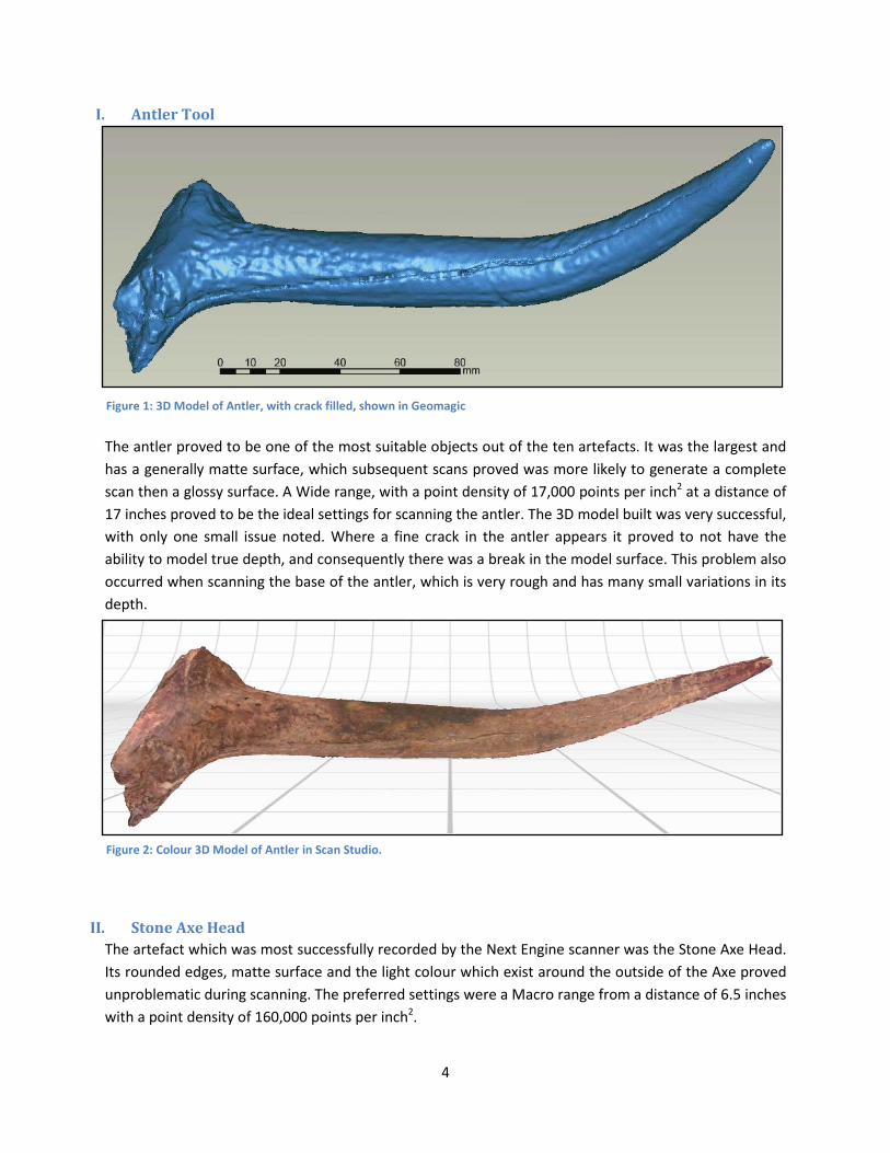
I. Antler Tool
The antler proved to be one of the most suitable objects out of the ten artefacts. It was the largest and has a generally matte surface, which subsequent scans proved was more likely to generate a complete scan then a glossy surface. A Wide range, with a point density of 17,000 points per inch2 at a distance of 17 inches proved to be the ideal settings for scanning the antler. The 3D model built was very successful, with only one small issue noted. Where a fine crack in the antler appears it proved to not have the ability to model true depth, and consequently there was a break in the model surface. This problem also occurred when scanning the base of the antler, which is very rough and has many small variations in its depth.
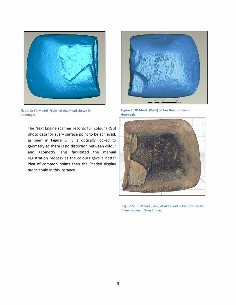
II. Stone Axe Head The artefact which was most successfully recorded by the Next Engine scanner was the Stone Axe Head. Its rounded edges, matte surface and the light colour which exist around the outside of the Axe proved unproblematic during scanning. The preferred settings were a Macro range from a distance of 6.5 inches with a point density of 160,000 points per inch2.
Figure 2: Colour 3D Model of Antler in Scan Studio.
Figure 1: 3D Model of Antler, with crack filled, shown in Geomagic
5
The Next Engine scanner records full colour (RGB) photo data for every surface point to be achieved, as seen in Figure 5. It is optically locked to geometry so there is no distortion between colour and geometry. This facilitated the manual registration process as the colours gave a better idea of common points than the Shaded display mode could in this instance.
Figure 3: 3D Model (Front) of Axe Head shown in Geomagic.
Figure 4: 3D Model (Back) of Axe Head shown in Geomagic.
Figure 5: 3D Model (Back) of Axe Head in Colour Display View shown in Scan Studio.
6
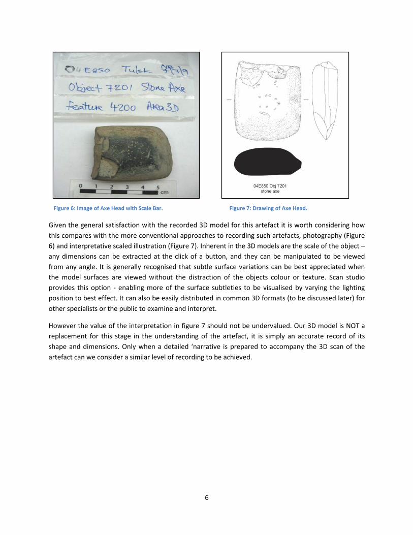
Given the general satisfaction with the recorded 3D model for this artefact it is worth considering how this compares with the more conventional approaches to recording such artefacts, photography (Figure 6) and interpretative scaled illustration (Figure 7). Inherent in the 3D models are the scale of the object – any dimensions can be extracted at the click of a button, and they can be manipulated to be viewed from any angle. It is generally recognised that subtle surface variations can be best appreciated when the model surfaces are viewed without the distraction of the objects colour or texture. Scan studio provides this option - enabling more of the surface subtleties to be visualised by varying the lighting position to best effect. It can also be easily distributed in common 3D formats (to be discussed later) for other specialists or the public to examine and interpret.
However the value of the interpretation in figure 7 should not be undervalued. Our 3D model is NOT a replacement for this stage in the understanding of the artefact, it is simply an accurate record of its shape and dimensions. Only when a detailed ‘narrative is prepared to accompany the 3D scan of the artefact can we consider a similar level of recording to be achieved.
Figure 6: Image of Axe Head with Scale Bar. Figure 7: Drawing of Axe Head.
7
III. Iron Horseshoe Fragment
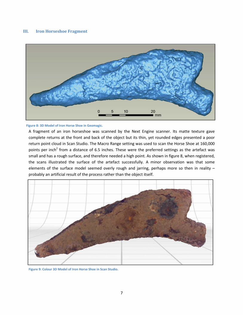
A fragment of an iron horseshoe was scanned by the Next Engine scanner. Its matte texture gave complete returns at the front and back of the object but its thin, yet rounded edges presented a poor return point cloud in Scan Studio. The Macro Range setting was used to scan the Horse Shoe at 160,000 points per inch2 from a distance of 6.5 inches. These were the preferred settings as the artefact was small and has a rough surface, and therefore needed a high point. As shown in figure 8, when registered, the scans illustrated the surface of the artefact successfully. A minor observation was that some elements of the surface model seemed overly rough and jarring, perhaps more so then in reality – probably an artificial result of the process rather than the object itself.
Figure 8: 3D Model of Iron Horse Shoe in Geomagic.
Figure 9: Colour 3D Model of Iron Horse Shoe in Scan Studio.
8
IV. Decorated Glass Bead
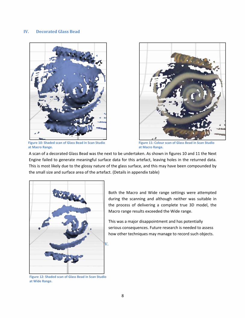
A scan of a decorated Glass Bead was the next to be undertaken. As shown in figures 10 and 11 the Next Engine failed to generate meaningful surface data for this artefact, leaving holes in the returned data. This is most likely due to the glossy nature of the glass surface, and this may have been compounded by the small size and surface area of the artefact. (Details in appendix table)
Both the Macro and Wide range settings were attempted during the scanning and although neither was suitable in the process of delivering a complete true 3D model, the Macro range results exceeded the Wide range.
This was a major disappointment and has potentially serious consequences. Future research is needed to assess how other techniques may manage to record such objects.
V.
Figure 11: Colour scan of Glass Bead in Scan Studio at Macro Range.
Figure 10: Shaded scan of Glass Bead in Scan Studio at Macro Range.
Figure 12: Shaded scan of Glass Bead in Scan Studio at Wide Range.
9
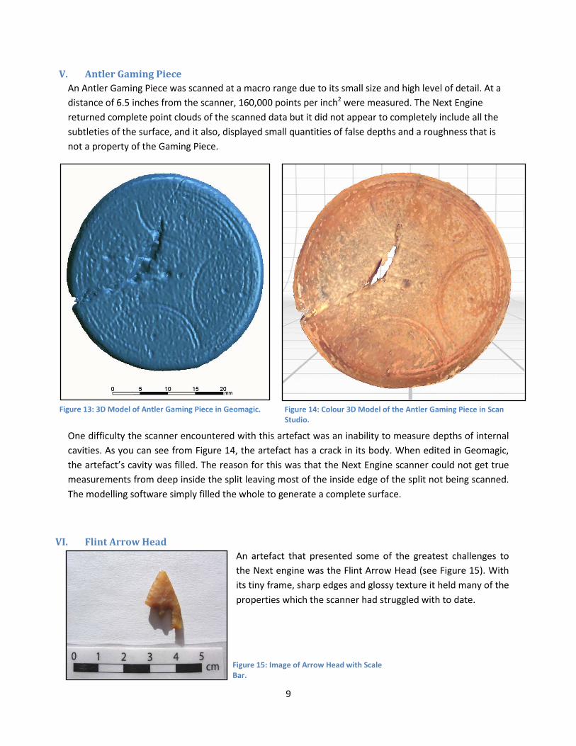
V. Antler Gaming Piece An Antler Gaming Piece was scanned at a macro range due to its small size and high level of detail. At a distance of 6.5 inches from the scanner, 160,000 points per inch2 were measured. The Next Engine returned complete point clouds of the scanned data but it did not appear to completely include all the subtleties of the surface, and it also, displayed small quantities of false depths and a roughness that is not a property of the Gaming Piece.
One difficulty the scanner encountered with this artefact was an inability to measure depths of internal cavities. As you can see from Figure 14, the artefact has a crack in its body. When edited in Geomagic, the artefact’s cavity was filled. The reason for this was that the Next Engine scanner could not get true measurements from deep inside the split leaving most of the inside edge of the split not being scanned. The modelling software simply filled the whole to generate a complete surface.
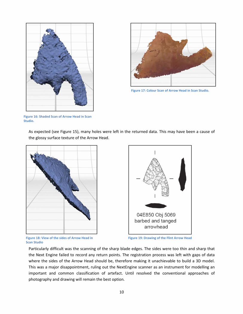
VI. Flint Arrow Head An artefact that presented some of the greatest challenges to the Next engine was the Flint Arrow Head (see Figure 15). With its tiny frame, sharp edges and glossy texture it held many of the properties which the scanner had struggled with to date.
Figure 13: 3D Model of Antler Gaming Piece in Geomagic. Figure 14: Colour 3D Model of the Antler Gaming Piece in Scan Studio.
Figure 15: Image of Arrow Head with Scale Bar.
10
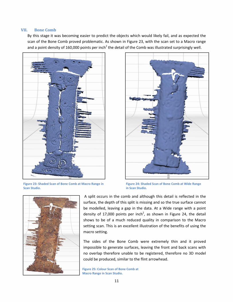
As expected (see Figure 15), many holes were left in the returned data. This may have been a cause of the glossy surface texture of the Arrow Head.
Particularly difficult was the scanning of the sharp blade edges. The sides were too thin and sharp that the Next Engine failed to record any return points. The registration process was left with gaps of data where the sides of the Arrow Head should be, therefore making it unachievable to build a 3D model. This was a major disappointment, ruling out the NextEngine scanner as an instrument for modelling an important and common classification of artefact. Until resolved the conventional approaches of photography and drawing will remain the best option.
Figure 16: Shaded Scan of Arrow Head in Scan Studio.
Figure 17: Colour Scan of Arrow Head in Scan Studio.
Figure 18: View of the sides of Arrow Head in Scan Studio
Figure 19: Drawing of the Flint Arrow Head
11
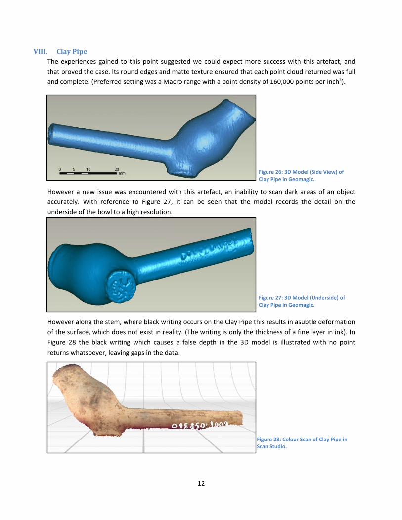
VII. Bone Comb By this stage it was becoming easier to predict the objects which would likely fail, and as expected the scan of the Bone Comb proved problematic. As shown in Figure 23, with the scan set to a Macro range and a point density of 160,000 points per inch2 the detail of the Comb was illustrated surprisingly well.
A split occurs in the comb and although this detail is reflected in the surface, the depth of this split is missing and so the true surface cannot be modelled, leaving a gap in the data. At a Wide range with a point density of 17,000 points per inch2, as shown in Figure 24, the detail shows to be of a much reduced quality in comparison to the Macro setting scan. This is an excellent illustration of the benefits of using the macro setting.
The sides of the Bone Comb were extremely thin and it proved impossible to generate surfaces, leaving the front and back scans with no overlap therefore unable to be registered, therefore no 3D model could be produced, similar to the flint arrowhead.
Figure 23: Shaded Scan of Bone Comb at Macro Range in Scan Studio.
Figure 24: Shaded Scan of Bone Comb at Wide Range in Scan Studio.
Figure 25: Colour Scan of Bone Comb at Macro Range in Scan Studio.
12
VIII. Clay Pipe The experiences gained to this point suggested we could expect more success with this artefact, and that proved the case. Its round edges and matte texture ensured that each point cloud returned was full and complete. (Preferred setting was a Macro range with a point density of 160,000 points per inch2).
However a new issue was encountered with this artefact, an inability to scan dark areas of an object accurately. With reference to Figure 27, it can be seen that the model records the detail on the underside of the bowl to a high resolution.
However along the stem, where black writing occurs on the Clay Pipe this results in asubtle deformation of the surface, which does not exist in reality. (The writing is only the thickness of a fine layer in ink). In Figure 28 the black writing which causes a false depth in the 3D model is illustrated with no point returns whatsoever, leaving gaps in the data.
Figure 27: 3D Model (Underside) of Clay Pipe in Geomagic.
Figure 28: Colour Scan of Clay Pipe in Scan Studio.
Figure 26: 3D Model (Side View) of Clay Pipe in Geomagic.
13
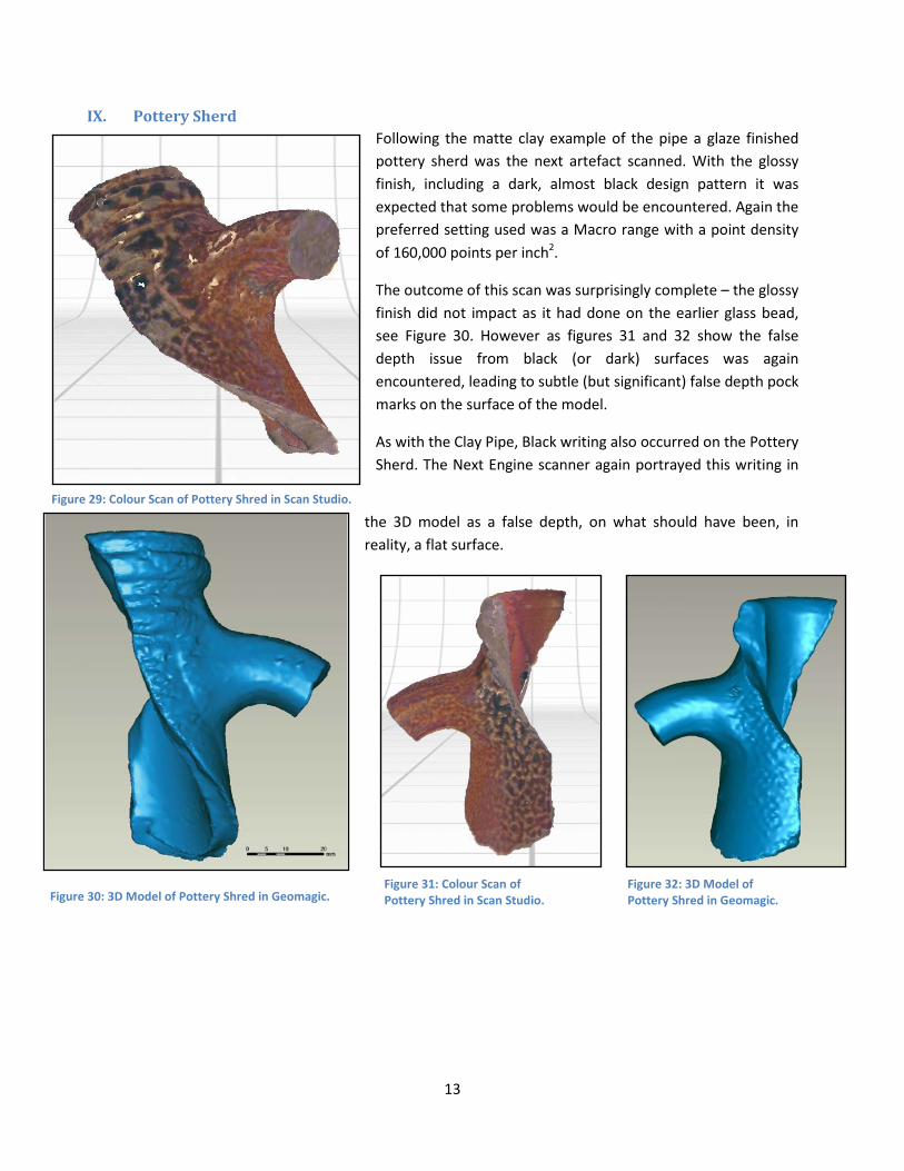
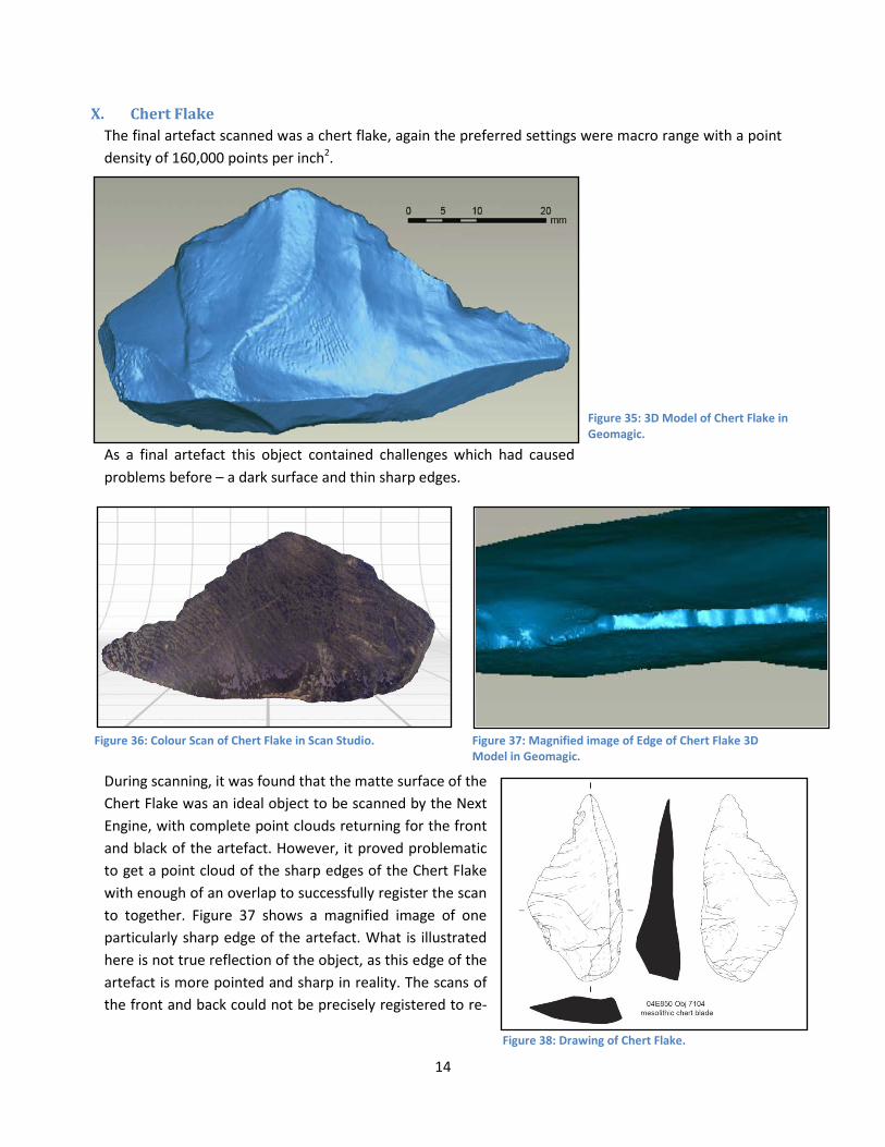
IX. Pottery Sherd Following the matte clay example of the pipe a glaze finished pottery sherd was the next artefact scanned. With the glossy finish, including a dark, almost black design pattern it was expected that some problems would be encountered. Again the preferred setting used was a Macro range with a point density of 160,000 points per inch2.
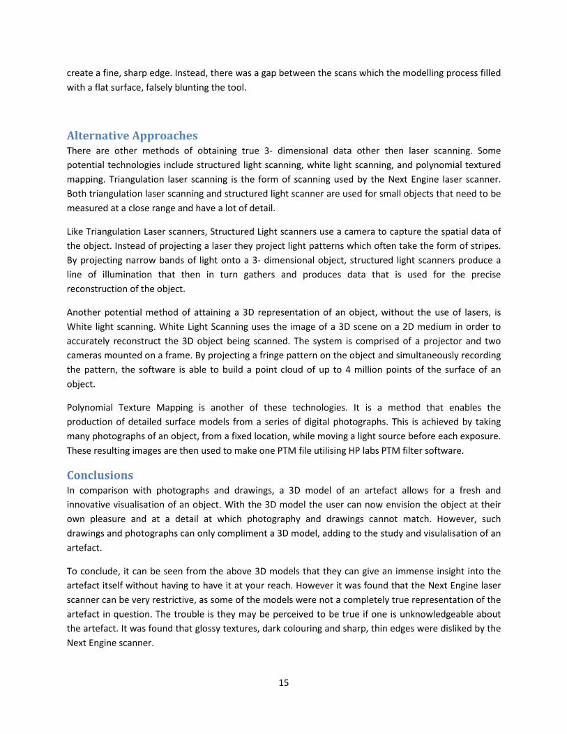
The outcome of this scan was surprisingly complete – the glossy finish did not impact as it had done on the earlier glass bead, see Figure 30. However as figures 31 and 32 show the false depth issue from black (or dark) surfaces was again encountered, leading to subtle (but significant) false depth pock marks on the surface of the model.
As with the Clay Pipe, Black writing also occurred on the Pottery Sherd. The Next Engine scanner again portrayed this writing in
the 3D model as a false depth, on what should have been, in reality, a flat surface.
Figure 31: Colour Scan of Pottery Shred in Scan Studio.
Figure 29: Colour Scan of Pottery Shred in Scan Studio.
Figure 30: 3D Model of Pottery Shred in Geomagic. Figure 32: 3D Model of Pottery Shred in Geomagic.
14
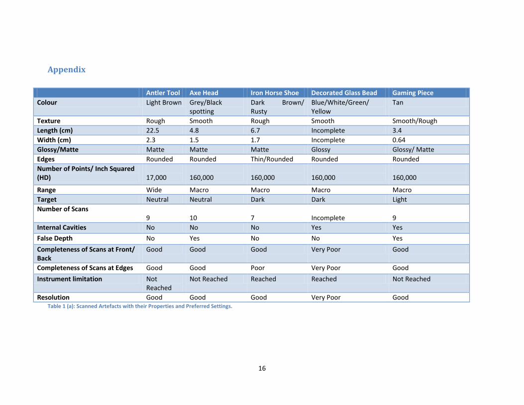
X. Chert Flake The final artefact scanned was a chert flake, again the preferred settings were macro range with a point density of 160,000 points per inch2.
As a final artefact this object contained challenges which had caused problems before – a dark surface and thin sharp edges.
During scanning, it was found that the matte surface of the Chert Flake was an ideal object to be scanned by the Next Engine, with complete point clouds returning for the front and black of the artefact. However, it proved problematic to get a point cloud of the sharp edges of the Chert Flake with enough of an overlap to successfully register the scan to together. Figure 37 shows a magnified image of one particularly sharp edge of the artefact. What is illustrated here is not true reflection of the object, as this edge of the artefact is more pointed and sharp in reality. The scans of the front and back could not be precisely registered to re-
Figure 35: 3D Model of Chert Flake in Geomagic.
Figure 36: Colour Scan of Chert Flake in Scan Studio. Figure 37: Magnified image of Edge of Chert Flake 3D Model in Geomagic.
Figure 38: Drawing of Chert Flake.
15
create a fine, sharp edge. Instead, there was a gap between the scans which the modelling process filled with a flat surface, falsely blunting the tool.
Alternative Approaches There are other methods of obtaining true 3- dimensional data other then laser scanning. Some potential technologies include structured light scanning, white light scanning, and polynomial textured mapping. Triangulation laser scanning is the form of scanning used by the Next Engine laser scanner. Both triangulation laser scanning and structured light scanner are used for small objects that need to be measured at a close range and have a lot of detail.
Like Triangulation Laser scanners, Structured Light scanners use a camera to capture the spatial data of the object. Instead of projecting a laser they project light patterns which often take the form of stripes. By projecting narrow bands of light onto a 3- dimensional object, structured light scanners produce a line of illumination that then in turn gathers and produces data that is used for the precise reconstruction of the object.
Another potential method of attaining a 3D representation of an object, without the use of lasers, is White light scanning. White Light Scanning uses the image of a 3D scene on a 2D medium in order to accurately reconstruct the 3D object being scanned. The system is comprised of a projector and two cameras mounted on a frame. By projecting a fringe pattern on the object and simultaneously recording the pattern, the software is able to build a point cloud of up to 4 million points of the surface of an object.
Polynomial Texture Mapping is another of these technologies. It is a method that enables the production of detailed surface models from a series of digital photographs. This is achieved by taking many photographs of an object, from a fixed location, while moving a light source before each exposure. These resulting images are then used to make one PTM file utilising HP labs PTM filter software.
Conclusions In comparison with photographs and drawings, a 3D model of an artefact allows for a fresh and innovative visualisation of an object. With the 3D model the user can now envision the object at their own pleasure and at a detail at which photography and drawings cannot match. However, such drawings and photographs can only compliment a 3D model, adding to the study and visulalisation of an artefact.
To conclude, it can be seen from the above 3D models that they can give an immense insight into the artefact itself without having to have it at your reach. However it was found that the Next Engine laser scanner can be very restrictive, as some of the models were not a completely true representation of the artefact in question. The trouble is they may be perceived to be true if one is unknowledgeable about the artefact. It was found that glossy textures, dark colouring and sharp, thin edges were disliked by the Next Engine scanner.
16
Appendix
Table 1 (a): Scanned Artefacts with their Properties and Preferred Settings.
Antler Tool Axe Head Iron Horse Shoe Decorated Glass Bead Gaming Piece Colour Light Brown Grey/Black
spotting Dark Brown/ Rusty
Blue/White/Green/ Yellow
Tan
Texture Rough Smooth Rough Smooth Smooth/Rough Length (cm) 22.5 4.8 6.7 Incomplete 3.4 Width (cm) 2.3 1.5 1.7 Incomplete 0.64 Glossy/Matte Matte Matte Matte Glossy Glossy/ Matte Edges Rounded Rounded Thin/Rounded Rounded Rounded Number of Points/ Inch Squared (HD)
17,000
160,000
160,000
160,000
160,000
Range Wide Macro Macro Macro Macro Target Neutral Neutral Dark Dark Light Number of Scans
9 10
7
Incomplete
9
Internal Cavities No No No Yes Yes
False Depth No Yes No No Yes
Completeness of Scans at Front/ Back
Good Good Good Very Poor Good
Completeness of Scans at Edges Good Good Poor Very Poor Good
Instrument limitation Not Reached
Not Reached Reached Reached Not Reached
Resolution Good Good Good Very Poor Good
17
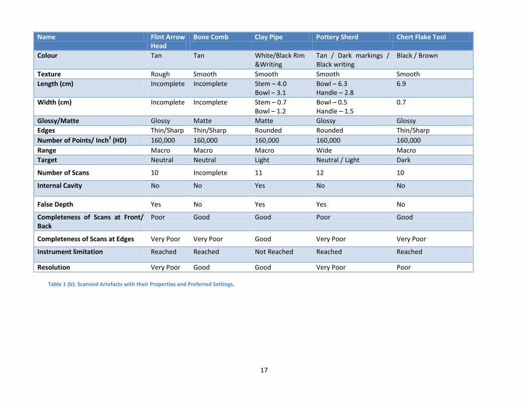
Table 1 (b): Scanned Artefacts with their Properties and Preferred Settings.
Name Flint Arrow Head
Bone Comb Clay Pipe Pottery Sherd Chert Flake Tool
Colour Tan Tan White/Black Rim &Writing
Tan / Dark markings / Black writing
Black / Brown
Texture Rough Smooth Smooth Smooth Smooth Length (cm) Incomplete Incomplete Stem – 4.0
Bowl – 3.1 Bowl – 6.3 Handle – 2.8
6.9
Width (cm) Incomplete Incomplete Stem – 0.7 Bowl – 1.2
Bowl – 0.5 Handle – 1.5
0.7
Glossy/Matte Glossy Matte Matte Glossy Glossy Edges Thin/Sharp Thin/Sharp Rounded Rounded Thin/Sharp Number of Points/ Inch2 (HD) 160,000 160,000 160,000 160,000 160,000 Range Macro Macro Macro Wide Macro Target Neutral Neutral Light Neutral / Light Dark
Number of Scans 10 Incomplete 11 12 10
Internal Cavity No No Yes No No
False Depth Yes No Yes Yes No
Completeness of Scans at Front/ Back
Poor Good Good Poor Good
Completeness of Scans at Edges Very Poor Very Poor Good Very Poor Very Poor
Instrument limitation Reached Reached Not Reached Reached Reached
Resolution Very Poor Good Good Very Poor Poor