art 3.1 user guide
TRANSCRIPT

Agilent Repair Tool Online Help
Printable Version
Intelligent Test Software Solutions
ITFSS 03.10 p 1204
January 2005
1
Table Of Contents
Introduction to the Agilent Repair Tool..............................................................5 Welcome to the Agilent Repair Tool (ART)...........................................................5
Key Features of the Agilent Repair Tool .............................................................6 Benefits of the Agilent Repair Tool .....................................................................8 Minimum System Requirements.........................................................................9 Agilent Technologies on the Web ................................................................... 10 Getting Help ....................................................................................................... 11
Printable Help File ................................................................................................. 12 Technical Support ................................................................................................. 13 Training Information.............................................................................................. 14
ITF Administration System ............................................................................... 15 Overview of the ITF Administration System ....................................................... 15 ART Settings .......................................................................................................... 16
Getting Started................................................................................................... 17 Login and Logout .................................................................................................. 17
Login ................................................................................................................... 17 Logout................................................................................................................. 19
Select Test Stages ................................................................................................. 20 Opening and Closing Boards ............................................................................... 21
Opening a Board................................................................................................ 21 Search for Board by Type ................................................................................. 23 Closing a Board.................................................................................................. 25
Change Password.................................................................................................. 26 Input Devices ......................................................................................................... 27
Barcode Reader ................................................................................................. 27 Keyboard and Mouse ........................................................................................ 28 Keyboard Shortcuts ........................................................................................... 29 Function Keys..................................................................................................... 33 Keypad ................................................................................................................ 34 Keypad Layout.................................................................................................... 35 Programming the Keypad ................................................................................. 36 Updating the Keypad Program......................................................................... 37
Board Navigation................................................................................................... 38 Find Component ................................................................................................ 38 Find Net .............................................................................................................. 40 Find Short ........................................................................................................... 43 Clear Highlights ................................................................................................. 45 Show Connected Trace..................................................................................... 46
2
Rotate Board....................................................................................................... 47 Zoom In, Zoom Out............................................................................................ 48 Zoom Full Board ................................................................................................ 49 Board Display Options ...................................................................................... 50 View Top Side of Board .................................................................................... 52 View Bottom Side of Board............................................................................... 53 View Both Sides of Board ................................................................................. 54 Find Connected Items ....................................................................................... 55 Status Bar Information ...................................................................................... 56 AOI Board Repair............................................................................................... 57
AOI Repair Procedure ........................................................................................... 57 Processing an AOI_SJ/AOI_SP defect............................................................ 62
Optical Image......................................................................................................... 64 View Large Image .............................................................................................. 64 Print Image ......................................................................................................... 66 Save Image ......................................................................................................... 67 AXI Board Repair ............................................................................................... 69
AXI Repair Procedure............................................................................................ 69 Processing an AXI defect .................................................................................. 75
X-ray Image............................................................................................................ 77 View Large Image .............................................................................................. 77 Select Image Slice ............................................................................................. 78 Print Image ......................................................................................................... 80 ICT Board Repair................................................................................................ 83
ICT Repair Procedure............................................................................................ 83 Processing an ICT defect .................................................................................. 89
View Board Layers................................................................................................. 91 Repair Actions.................................................................................................... 93
Repaired ................................................................................................................. 93 Repair Later ............................................................................................................ 94 False Call ................................................................................................................ 95 Variation OK ........................................................................................................... 96 Defect Status .......................................................................................................... 97 Undo Repair Action............................................................................................... 98
Defect Details ..................................................................................................... 99 Print Repair Report .......................................................................................... 102 In-line Repair ................................................................................................... 103 Administrator Reference................................................................................. 104
ART Data Source .............................................................................................. 104 Scrap Board ......................................................................................................... 105 Board Buffering for AOI_SP/AOI_SP ................................................................ 106
3
Add Board Serial Number .................................................................................. 108 ART Settings ........................................................................................................ 109 Tools > Administration Dialog boxes................................................................ 110
Troubleshooting .............................................................................................. 115 Trouble Opening Boards .................................................................................... 115 Trouble Saving Images ....................................................................................... 116 Trouble Viewing Buttons .................................................................................... 118 Trouble with Barcode Readers........................................................................... 119 Trouble with Images............................................................................................ 121 Trouble with Login .............................................................................................. 123 Error Messages.................................................................................................... 124
Copyrights and Notices................................................................................... 131 Appendixes ...................................................................................................... 132
Starting up the Software ..................................................................................... 132 How ART uses IPC Standards ............................................................................ 133 Intelligent Test Framework................................................................................. 134 ART Data Source ................................................................................................. 135 ART and TestWise SPC....................................................................................... 136 RLE Codes ............................................................................................................ 138 User Roles ............................................................................................................ 140 Working in Comfort ............................................................................................. 141
Glossary ............................................................................................................ 142 Index.................................................................................................................. 150
4
Introduction to the Agilent Repair Tool
Welcome to the Agilent Repair Tool (ART)
The Agilent Repair Tool (ART) is a printed circuit board repair tool that supports a common graphical user interface for all three types of Agilent Technologies automated inspection systems: X-ray (AXI), Optical (AOI_SJ/AOI_SP), and in-circuit test (ICT). With this tool, operators can leverage skills, knowledge, and training across AXI, AOI_SJ, AOI_SP, and ICT repair loops. This increases the efficiency of repair and provides a more consistent method for reporting repair efforts.
Here are four easy ways to get the information you need.
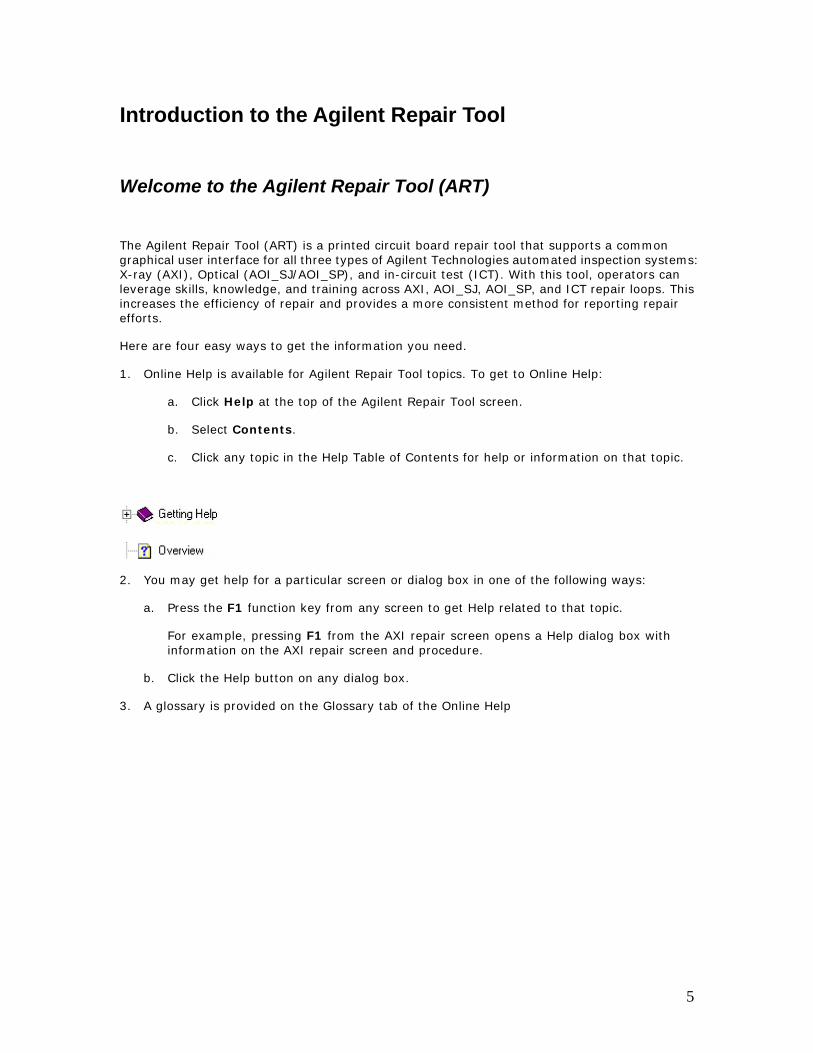
1. Online Help is available for Agilent Repair Tool topics. To get to Online Help:
a. Click Help at the top of the Agilent Repair Tool screen.
b. Select Contents.
c. Click any topic in the Help Table of Contents for help or information on that topic.
2. You may get help for a particular screen or dialog box in one of the following ways:
a. Press the F1 function key from any screen to get Help related to that topic.
For example, pressing F1 from the AXI repair screen opens a Help dialog box with information on the AXI repair screen and procedure.
b. Click the Help button on any dialog box.
3. A glossary is provided on the Glossary tab of the Online Help
5
Key Features of the Agilent Repair Tool Features common to AXI, ICT, AOI_SJ and AOI_SP:
• Simple interface guides the operator through repair.
• Allows any repair station to repair any board tested by an Agilent 3070, 5DX, SP, or SJ Series inspection system.
• Provides a mechanism to record the repair actions performed and other related information.
• Allows repair actions to be recorded for an entire component with a component-level defect.
• Ability to flag defects for later repair when tools or capabilities are not immediately available.
• Allows the operator to modify a reported defect.
• Provides the operator or engineer with information to decide whether the test call is a real defect.
• Based upon ANSI/IPC standard: ANSI/IPC-2511 (GenCAM).
• Allows the operator to search for any component on the board.
• Includes the ITF Administration System for configuring system properties, such as user access repair configurations, and framework services.
• Can be used with a keypad input device for AXI, AOI_SJ and AOI_SP.
AXI – specific features:
• Displays X-ray image with the associated fault information.
• Allows the user to zoom in, zoom out, print and save X-ray images.
• Provides test results and images from the test and inspection process.
• Displays the actual X-ray image used to make the test call, allowing the operator to validate the fault.
ICT – specific features:
• Displays In-circuit Report Ticket along with test failure information.
• Provides the first graphical repair solution from Agilent Technologies for the Agilent 3070 test system.
• Allows the operator to search for a common net between components.
• Suggests likely locations of shorts when unexpected shorts are detected between nodes.
6
AOI_SJ/AOI_SP – specific features:
• Displays optical image with the associated fault information.
• Support for SJ-10, SJ-50, and SP-50 in-line and off-line review and repair of printed circuit boards.
• Allows for integration of a JOT conveyor system, PC, and keypad for in-line configurations.
• Displays the actual image used to make the test call, allowing the operator to validate the fault.
7
Benefits of the Agilent Repair Tool Versatile Solution
• One repair tool works with AXI, AOI_SJ, AOI_SP, and ICT test systems.
• The skills you learn with the Agilent Repair Tool apply to AXI, AOI_SJ, AOI_SP, and ICT repair.
Easy to Use
• Simple design is intuitive, making ART easy to learn.
• Common Microsoft Windows® user interface look and feel.
• Each Client PC gives you access to board repair results for AXI, AOI_SJ, AOI_SP, and ICT.
Interoperability
• Built upon ANSI/IPC XML standards.
• Standard format based upon the ANSI/IPC standard 2511 (GenCAM).
8
Minimum System Requirements For the Agilent Repair Tool to work correctly, communication links must exist among the Intelligent Test Framework Server, Client PCs, and test systems. The test systems can be any combination of Agilent 3070, 5DX, SJ, and/or SP Series test systems. The following minimum system requirements are necessary in order to establish these communication links:
1. Client PCs with the following minimum requirements:
Hardware:
• Intel® Pentium III 800 MHz or higher
• 512 MB RAM
• Minimum 500 MB of free disk space
• 10/100 TX NIC
• 17" monitor (19" or 21" recommended), SVGA or higher resolution (1024 x 768, 256 colors)
Software:
• Microsoft® Windows 2000, Service Pack 4
• Microsoft® Windows XP, Service Pack 2
Microsoft® Windows NT 4 SP6a is not supported.
2. Test systems with the following software versions:
Agilent ICT UNIX with software version 04.00p or later
Agilent ICT WN with software version 3070 04.00p WN or later
Agilent AXI with software version 7.3 or later
Agilent AOI SJ Series with software version 4.07 or later
Agilent AOI SP Series with software version 2.0.0.7 or later
The minimum installation requires one Client PC and the Intelligent Test Framework (ITF) Server. The individual installation will determine the combination of Agilent 3070 UNIX, Agilent 3070 MS Windows, Agilent SJ Series and/or Agilent 5DX systems connected to the ITF Server and the Client PCs.
9
Agilent Technologies on the Web The Electronic Manufacturing Test (EMT) Technical Support web site is for the benefit of owners and users of the Agilent Repair Tool, the Agilent Quality Tool, and Agilent Technologies' board test and inspection systems.
Technical Support web address: http://www.agilent.com/see/support
Click Login/Registration.
If you are a registered member,
• Enter your User Name and Password
If you are not yet a registered member:
• Follow the online registration instructions
• You will receive a User Name and Password by email.
Topics available from the EMT Technical Support web site:
• Accessories, Updates, and Downloads
• Technical Answers and Services
For more information about Agilent Technologies’ products and services in electronics manufacturing, visit our web site: http://www.agilent.com/go/manufacturing
To learn about other Agilent Technologies test and measurement products, applications and services, or for a current sales office listing, visit our web site: http://www.agilent.com/find/tmdir
10

Getting Help
Page-Sensitive Help Press F1 from any screen to get Help related to that topic.
For example, pressing F1 from the AXI repair screen opens a Help dialog box with information on the AXI repair screen and procedure.
11
Printable Help File To view a printable version of the Agilent Repair Tool Online Help,
Click Start > Programs > ITF Software Solutions > Agilent Repair Tool > Printable Help
• The file will automatically open.
• Print the file if you wish.
If you see an "Open With" dialog box, your system does not know which program to use to open the Printable Help file. This means that you must install Acrobat Reader on your system before you can open the Printable Help file. Adobe Acrobat Reader software is provided with the Agilent Repair Tool. It is also available from the Adobe web site at http://www.adobe.com.
Adobe®, and Acrobat® are U.S. registered trademarks of Adobe Systems Incorporated.
12
Technical Support Agilent Repair Tool information is available in the following ways:
Web site support:
The Electronic Manufacturing Test (EMT) Technical Support web site is for the benefit of owners and users of the Agilent Repair Tool, the Agilent Quality Tool, and Agilent Technologies' board test and inspection systems.
Technical Support web address: http://www.agilent.com/see/support
Click Login/Registration.
If you are a registered member,
• Enter your User Name and Password
If you are not yet a registered member:
• Follow the online registration instructions
• You will receive a User Name and Password by email.
Phone support:
• Phone-based support is free for the first year and highly recommended for subsequent years.
• Customers in the U.S. can call a 24-hour toll free support phone number: 1-800-447-TEST.
• For customers outside the U.S., please contact your Agilent Technologies representative.
For more information about support services, go to the Agilent Technologies web site a http://www.agilent.com/see/support or contact your local field representative.
13

Training Information Electronic Manufacturing Test Technical Support web site
A list of training options is available on the EMT technical support web site.
a. Connect to the EMT Technical Support web site: http://www.agilent.com/see/support
b. Click the Education link.
14
ITF Administration System Overview of the ITF Administration System The ITF Administration System is a browser-based application used to configure system properties, such as user access, repair configurations and framework services within the Agilent Repair Tool and other applications.
The purpose of the ITF Administration System is to provide user security and to control functionality for the following information:
• Users
• Agilent Repair Tool: AOI_SJ, AOI_SP, AXI and ICT
• Agilent Quality Tool: AOI_SJ, AOI_SP, and AXI
• Intelligent Test Framework (ITF)
15
ART Settings System administrators can use the ITF Administration System to configure the following ART features:
• Status buttons
• Close board dialog box
• Repair actions
• Function keys
• Defect list
• Test station names
For more information, see the ITF Administration System online help.
16
Getting StartedLogin and Logout
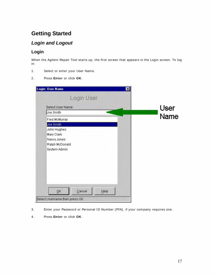
Login When the Agilent Repair Tool starts up, the first screen that appears is the Login screen. To log in:
1. Select or enter your User Name.
2. Press Enter or click OK.
3. Enter your Password or Personal ID Number (PIN), if your company requires one.
4. Press Enter or click OK.
17
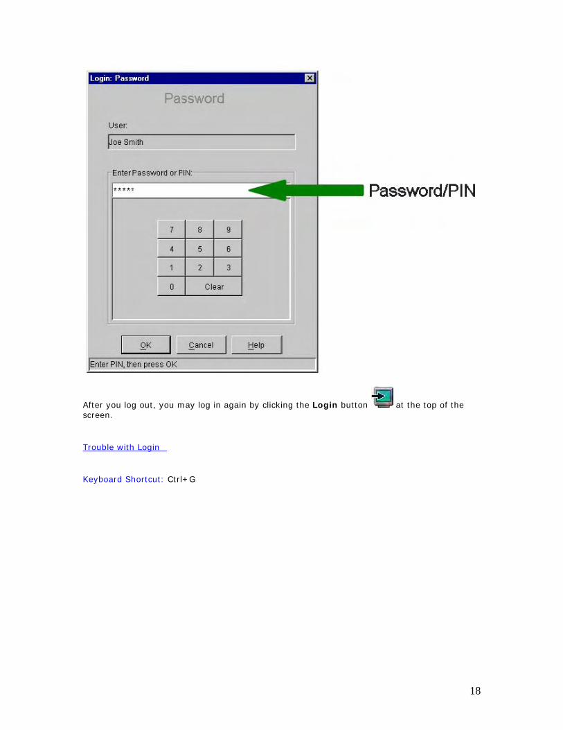
After you log out, you may log in again by clicking the Login button at the top of the screen.
Trouble with Login
Keyboard Shortcut: Ctrl+G
18
Logout
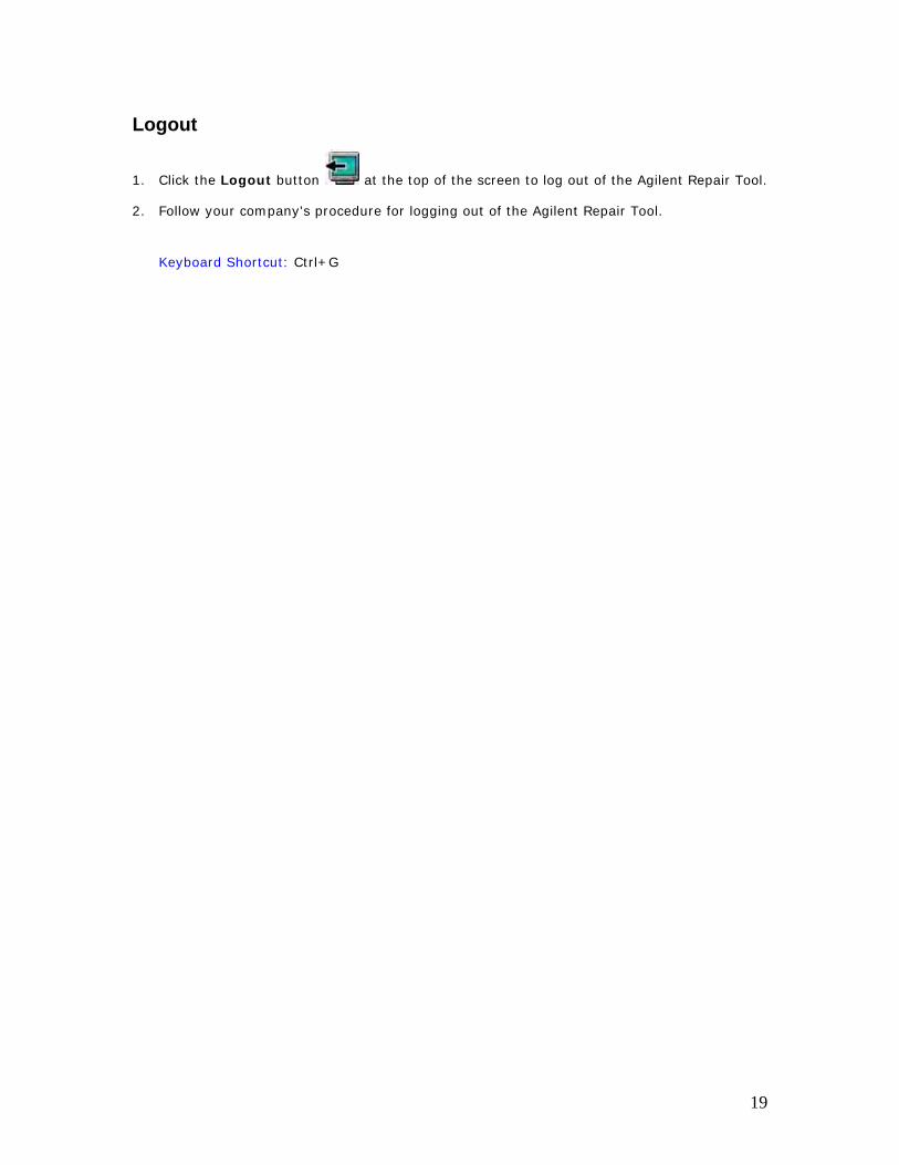
1. Click the Logout button at the top of the screen to log out of the Agilent Repair Tool.
2. Follow your company's procedure for logging out of the Agilent Repair Tool.
Keyboard Shortcut: Ctrl+G
19
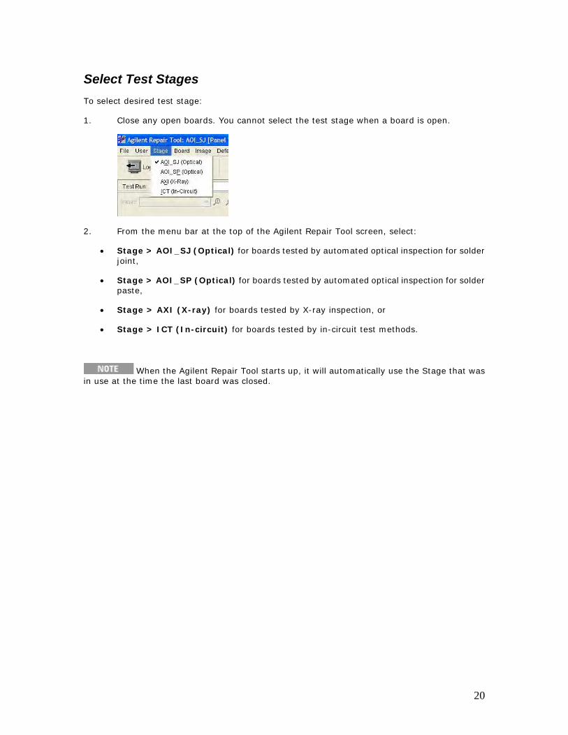
Select Test Stages To select desired test stage:
1. Close any open boards. You cannot select the test stage when a board is open.
2. From the menu bar at the top of the Agilent Repair Tool screen, select:
• Stage > AOI_SJ (Optical) for boards tested by automated optical inspection for solder joint,
• Stage > AOI_SP (Optical) for boards tested by automated optical inspection for solder paste,
• Stage > AXI (X-ray) for boards tested by X-ray inspection, or
• Stage > ICT (In-circuit) for boards tested by in-circuit test methods.
When the Agilent Repair Tool starts up, it will automatically use the Stage that was in use at the time the last board was closed.
20
Opening and Closing Boards
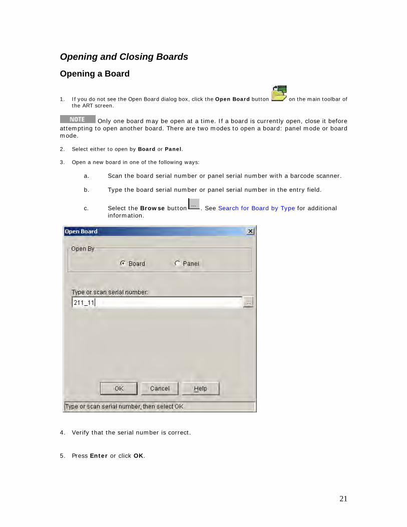
Opening a Board
1. If you do not see the Open Board dialog box, click the Open Board button on the main toolbar of the ART screen.
Only one board may be open at a time. If a board is currently open, close it before attempting to open another board. There are two modes to open a board: panel mode or board mode.
2. Select either to open by Board or Panel.
3. Open a new board in one of the following ways:
a. Scan the board serial number or panel serial number with a barcode scanner.
b. Type the board serial number or panel serial number in the entry field.
c. Select the Browse button . See Search for Board by Type for additional information.
4. Verify that the serial number is correct.
5. Press Enter or click OK.
21
Notes:
1. The Open Board dialog box is usually displayed after a user logs in to the Agilent Repair Tool. These permissions are set up in the ITF Administration System.
2. If the Open Board dialog box does not appear and the Open Board button at the top of the screen is disabled, this user does not have permission to open a board. See your system administrator for further information.
3. Panel serial number vs. board serial number:
• If you scan or enter a board serial number, ART will open the test results for that specific board.
• If you scan or enter a panel serial number, ART will open all the test results for that panel, which may contain multiple instances of a board. Please note that panel-based serialization is not currently supported for ICT. It is, however, supported for both AXI, AOI_SJ, and AOI_SP.
When using In-line mode, there is no panel or board view mode.
Keyboard Shortcut: Ctrl+O
22
Search for Board by Type
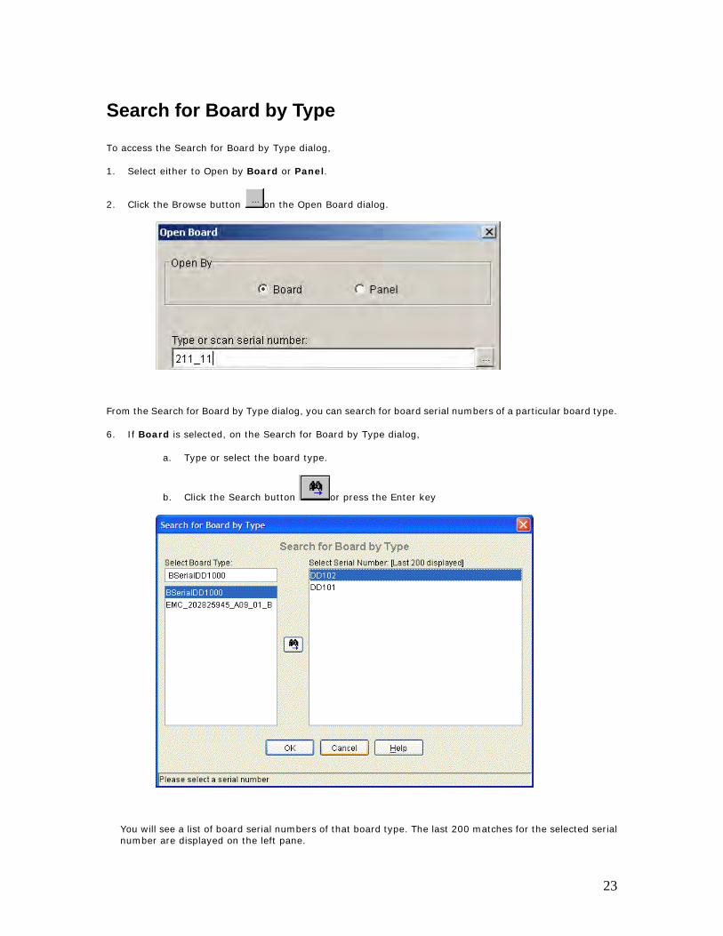
To access the Search for Board by Type dialog,
1. Select either to Open by Board or Panel.
2. Click the Browse button on the Open Board dialog.
From the Search for Board by Type dialog, you can search for board serial numbers of a particular board type.
6. If Board is selected, on the Search for Board by Type dialog,
a. Type or select the board type.
b. Click the Search button or press the Enter key
You will see a list of board serial numbers of that board type. The last 200 matches for the selected serial number are displayed on the left pane.
23
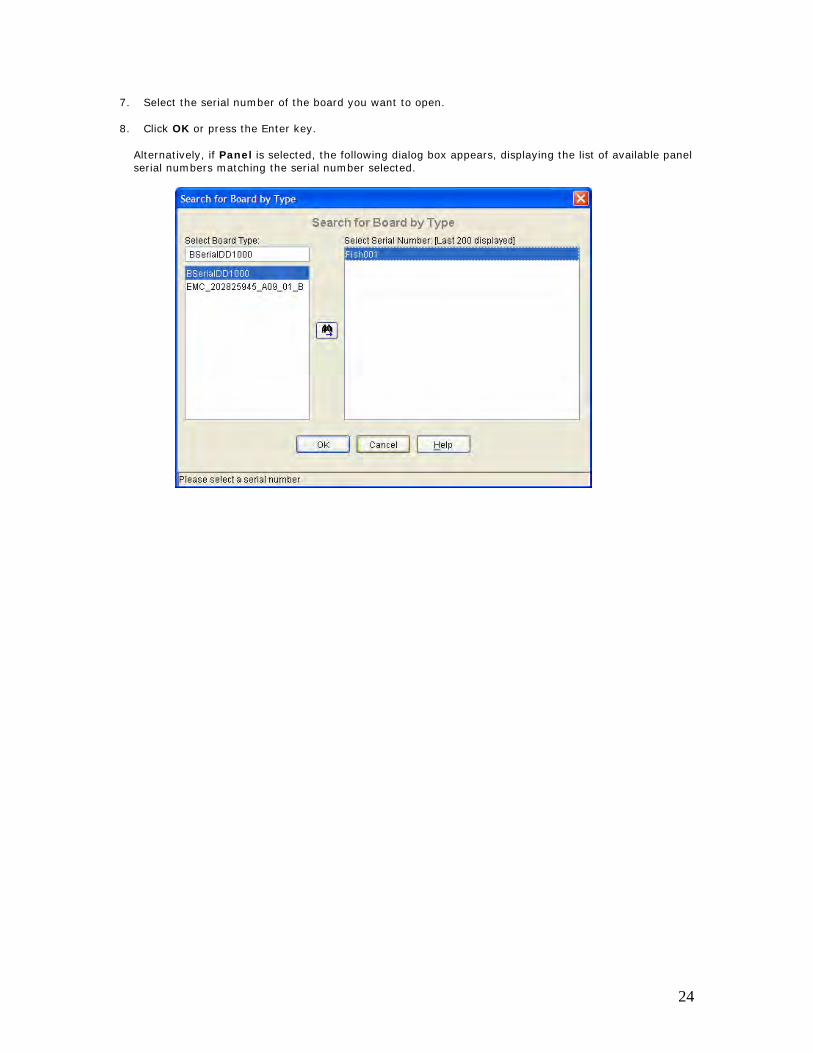
7. Select the serial number of the board you want to open.
8. Click OK or press the Enter key.
Alternatively, if Panel is selected, the following dialog box appears, displaying the list of available panel serial numbers matching the serial number selected.
24
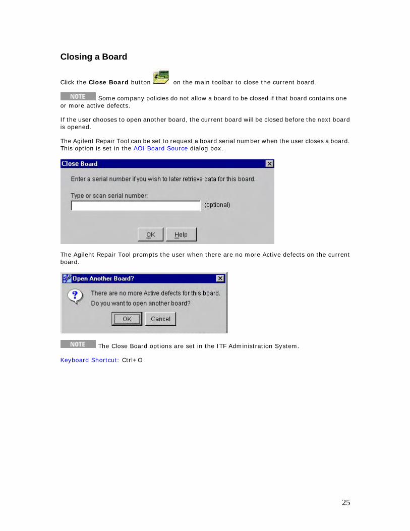
Closing a Board
Click the Close Board button on the main toolbar to close the current board.
Some company policies do not allow a board to be closed if that board contains one or more active defects.
If the user chooses to open another board, the current board will be closed before the next board is opened.
The Agilent Repair Tool can be set to request a board serial number when the user closes a board. This option is set in the AOI Board Source dialog box.
The Agilent Repair Tool prompts the user when there are no more Active defects on the current board.
The Close Board options are set in the ITF Administration System.
Keyboard Shortcut: Ctrl+O
25
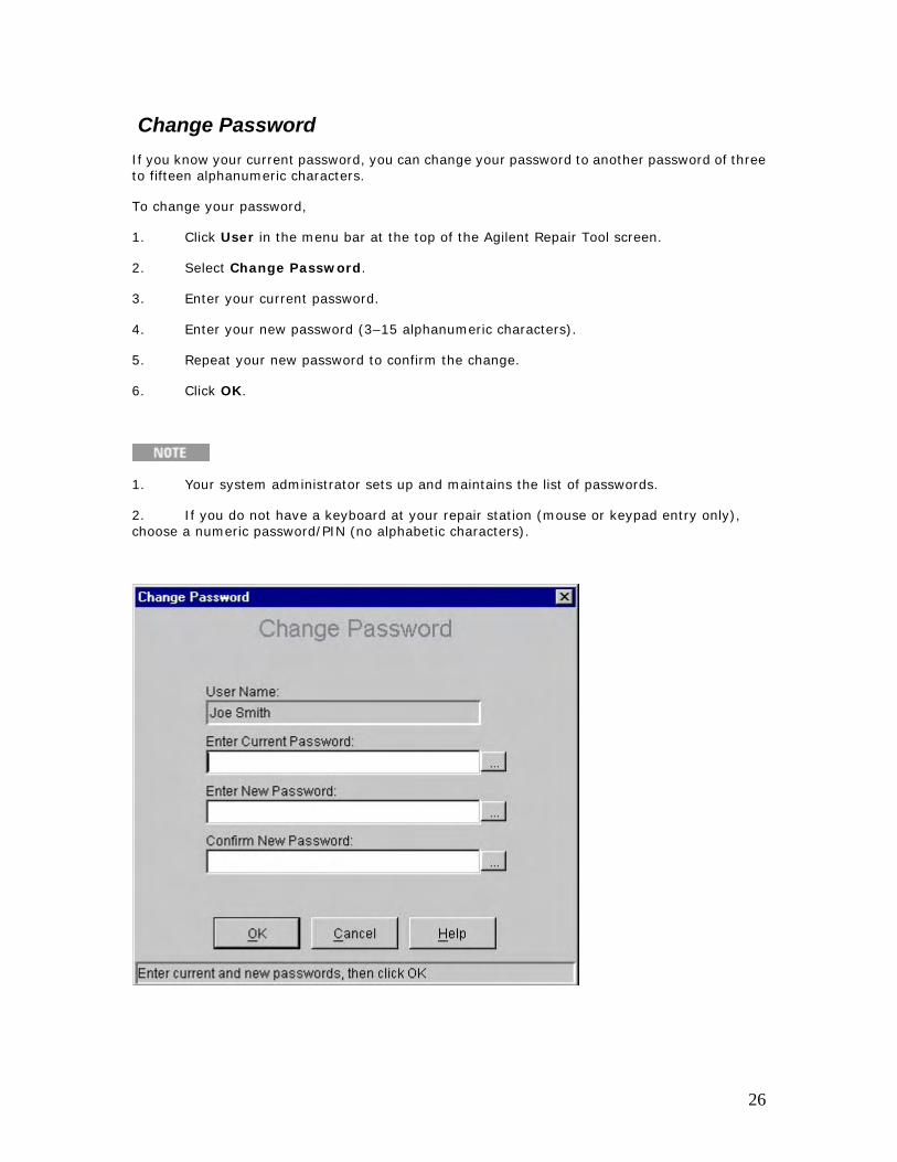
Change Password If you know your current password, you can change your password to another password of three to fifteen alphanumeric characters.
To change your password,
1. Click User in the menu bar at the top of the Agilent Repair Tool screen.
2. Select Change Password.
3. Enter your current password.
4. Enter your new password (3–15 alphanumeric characters).
5. Repeat your new password to confirm the change.
6. Click OK.
1. Your system administrator sets up and maintains the list of passwords.
2. If you do not have a keyboard at your repair station (mouse or keypad entry only), choose a numeric password/PIN (no alphabetic characters).
26
Input Devices
Barcode Reader To open a board using a barcode reader,
1. If the Open Board dialog box is not visible, click the Open Board button on the main toolbar at the top of the screen.
2. Scan the serial number of the board or panel with the barcode reader.
3. Verify the serial number and click OK.
A PS/2 or RS232 barcode reader may be used with the Client PC. If you are using an RS232 barcode reader, refer to Appendix C in the ITF Software Solutions Setup Guide.
Refer to the Agilent Electronic Manufacturing Test (EMT) Technical Support web site for additional information on how to purchase Agilent Repair Tool accessories. The EMT Technical Support web site address is: http://www.agilent.com/see/support
Click Supplies and Accessories; then click Electronic Manufacturing Test Online Accessory Catalog.
27

Keyboard and Mouse A keyboard and mouse together provide the most flexibility for entering information into and using the Agilent Repair Tool.
28
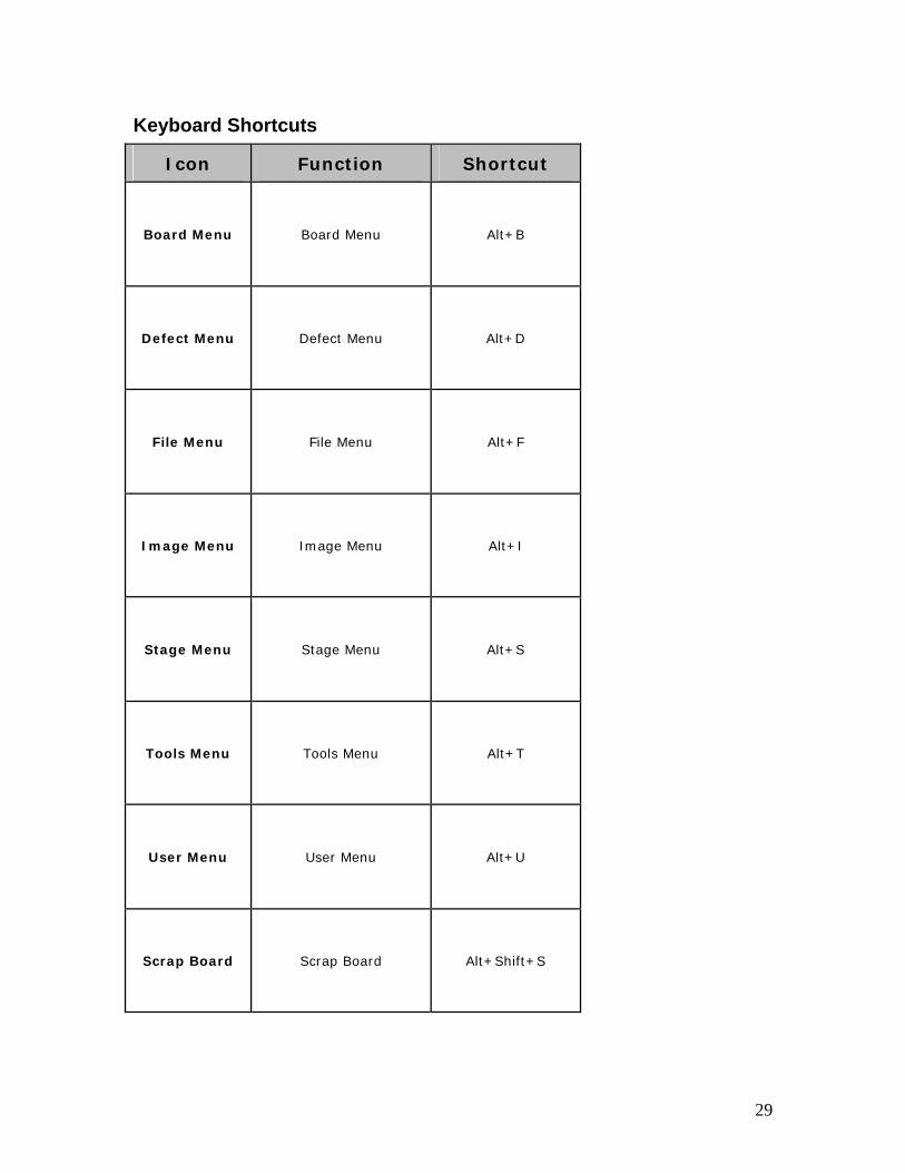
Keyboard Shortcuts
Icon Function Shortcut
Board Menu Board Menu Alt+B
Defect Menu Defect Menu Alt+D
File Menu File Menu Alt+F
Image Menu Image Menu Alt+I
Stage Menu Stage Menu Alt+S
Tools Menu Tools Menu Alt+T
User Menu User Menu Alt+U
Scrap Board Scrap Board Alt+Shift+S
29
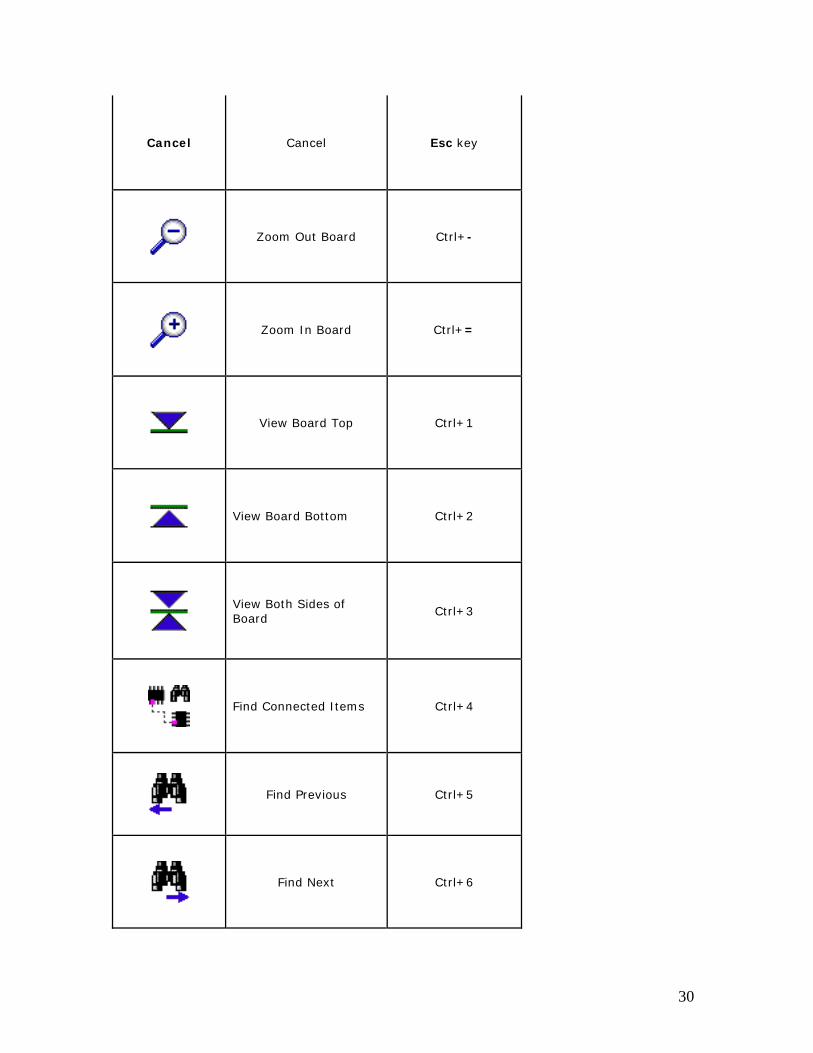
Cancel Cancel Esc key
Zoom Out Board Ctrl+-
Zoom In Board Ctrl+=
View Board Top Ctrl+1
View Board Bottom Ctrl+2
View Both Sides of Board
Ctrl+3
Find Connected Items Ctrl+4
Find Previous Ctrl+5
Find Next Ctrl+6
30
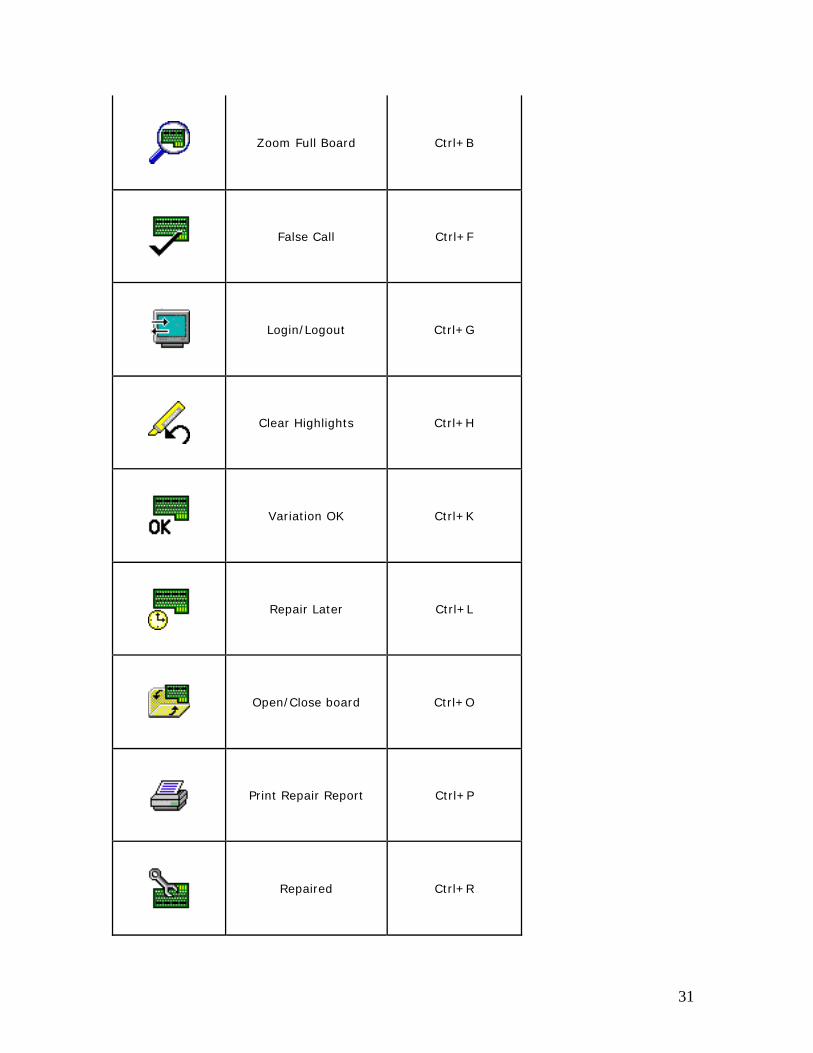
Zoom Full Board Ctrl+B
False Call Ctrl+F
Login/Logout Ctrl+G
Clear Highlights Ctrl+H
Variation OK Ctrl+K
Repair Later Ctrl+L
Open/Close board Ctrl+O
Print Repair Report Ctrl+P
Repaired Ctrl+R
31
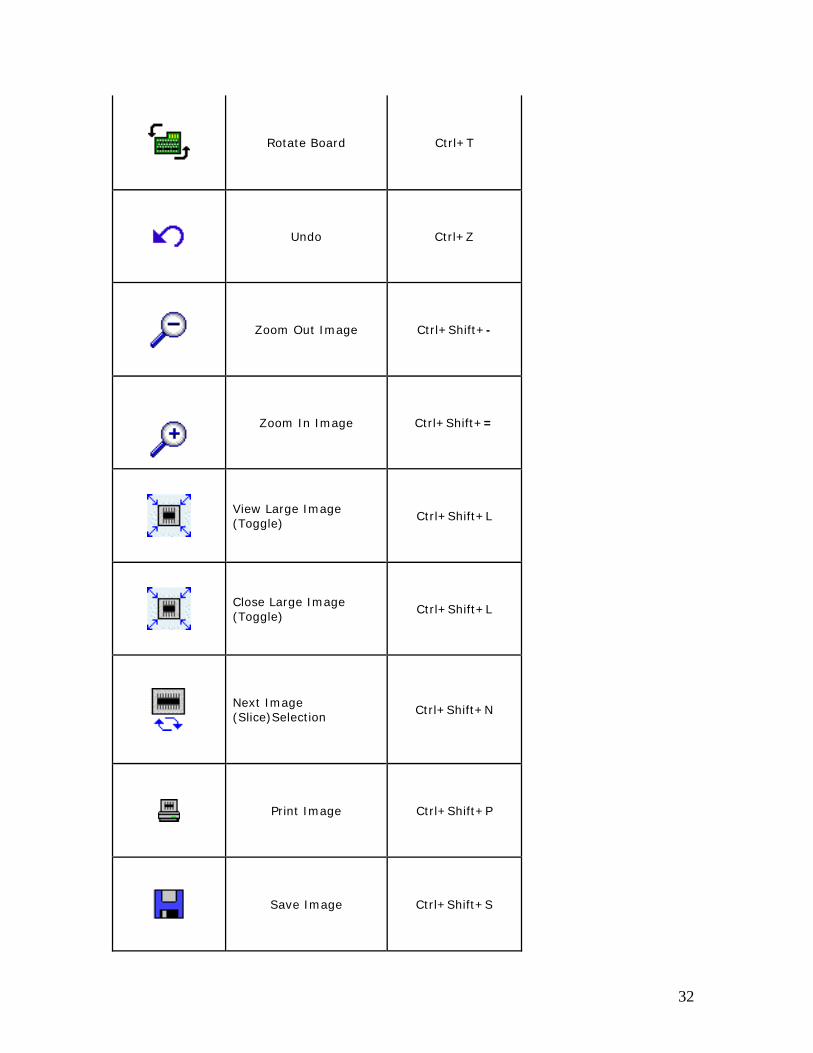
Rotate Board Ctrl+T
Undo Ctrl+Z
Zoom Out Image Ctrl+Shift+-
Zoom In Image Ctrl+Shift+=
View Large Image (Toggle)
Ctrl+Shift+L
Close Large Image (Toggle)
Ctrl+Shift+L
Next Image (Slice)Selection
Ctrl+Shift+N
Print Image Ctrl+Shift+P
Save Image Ctrl+Shift+S
32
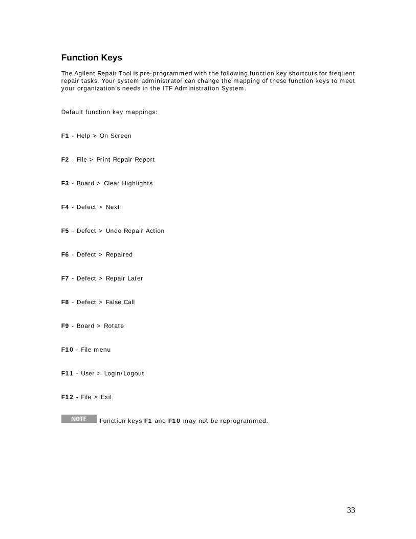
Function Keys The Agilent Repair Tool is pre-programmed with the following function key shortcuts for frequent repair tasks. Your system administrator can change the mapping of these function keys to meet your organization’s needs in the ITF Administration System.
Default function key mappings:
F1 - Help > On Screen
F2 - File > Print Repair Report
F3 - Board > Clear Highlights
F4 - Defect > Next
F5 - Defect > Undo Repair Action
F6 - Defect > Repaired
F7 - Defect > Repair Later
F8 - Defect > False Call
F9 - Board > Rotate
F10 - File menu
F11 - User > Login/Logout
F12 - File > Exit
Function keys F1 and F10 may not be reprogrammed.
33
Keypad A keypad is an optional input device for an AXI or AOI_SJ/AOI_SP repair operator using the Agilent Repair Tool. The press of a key on the keypad is equivalent to a click on the corresponding button on the repair screen with a mouse or keyboard stroke.
There are several reasons why a company may want to use a keypad:
• To save space on the work surface
• To speed up frequently-performed tasks
• For ease of use for operators not familiar with a keyboard or mouse
• To increase ergonomic comfort
See Keypad Layout for information on the arrangement of function keys on the keypad.
Refer to the Agilent Electronic Manufacturing Test (EMT) Technical Support web site for additional information on how to purchase the optional keypad for the Agilent Repair Tool. The EMT Technical Support web site address is:
http://www.agilent.com/see/support
Click Supplies and Accessories.
34
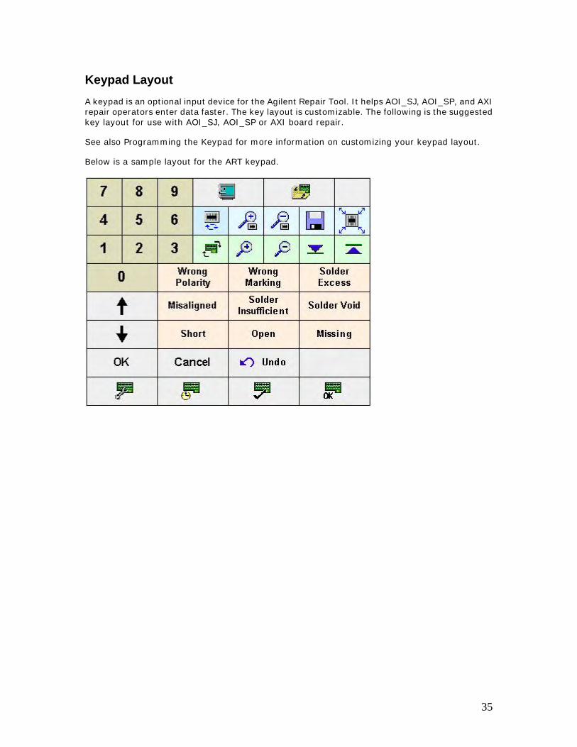
Keypad Layout A keypad is an optional input device for the Agilent Repair Tool. It helps AOI_SJ, AOI_SP, and AXI repair operators enter data faster. The key layout is customizable. The following is the suggested key layout for use with AOI_SJ, AOI_SP or AXI board repair.
See also Programming the Keypad for more information on customizing your keypad layout.
Below is a sample layout for the ART keypad.
35

Programming the Keypad If you purchased an optional keypad for the Agilent Repair Tool, the keypad will be programmed with the most commonly used functions. If you need to reprogram the keypad, consult the instructions in the keypad manufacturer's manual.
36
Updating the Keypad Program When you purchase an optional keypad for the Agilent Repair Tool, the keypad is programmed with the most commonly used functions. If, in a later ART software update, you are instructed to update the keypad program, please follow the instructions below.
1. Get the keypad User's manual and the Tipro keypad software.
a. Insert the CD in the CD drive on your Client PC.
b. Browse the CD to find the MID User's manual.
c. Save the MID User's manual to disk (on the Client PC).
d. Optional: Print the MID User's manual.
2. Install the keypad software on the Client PC.
a. At the Client PC, browse to the MIDWIN_xxx.EXE file location on the CD.
b. Double-click the MIDWIN_xxx.EXE file to install the keypad programming software.
3. Go to the Agilent Technical Support web site to get the latest ART keypad layout program.
a. Log in to the Technical Support web site.
b. Click Agilent Repair Tool.
c. Click Updates and Releases.
d. Click the link for the new ART software version installed on the Client PC.
e. Click Agilent Repair Tool (version#) Keypad Patch.
f. Continue by following the instructions on the Technical Support web site.
The characters "xxx" indicate a software version from Tipro. MIDWIN_xxx.EXE could be MIDWIN_309.EXE or a later version.
If defect names are translated into "display names" in your local language on the ITF Server, you will also want to reprogram the corresponding keypad keys for those defect names.
37
Board Navigation
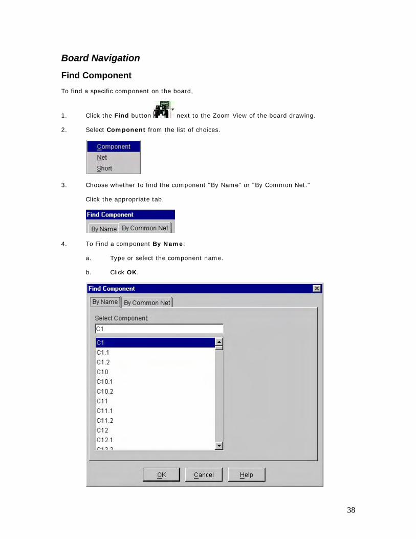
Find Component To find a specific component on the board,
1. Click the Find button next to the Zoom View of the board drawing.
2. Select Component from the list of choices.
3. Choose whether to find the component "By Name" or "By Common Net."
Click the appropriate tab.
4. To Find a component By Name:
a. Type or select the component name.
b. Click OK.
38
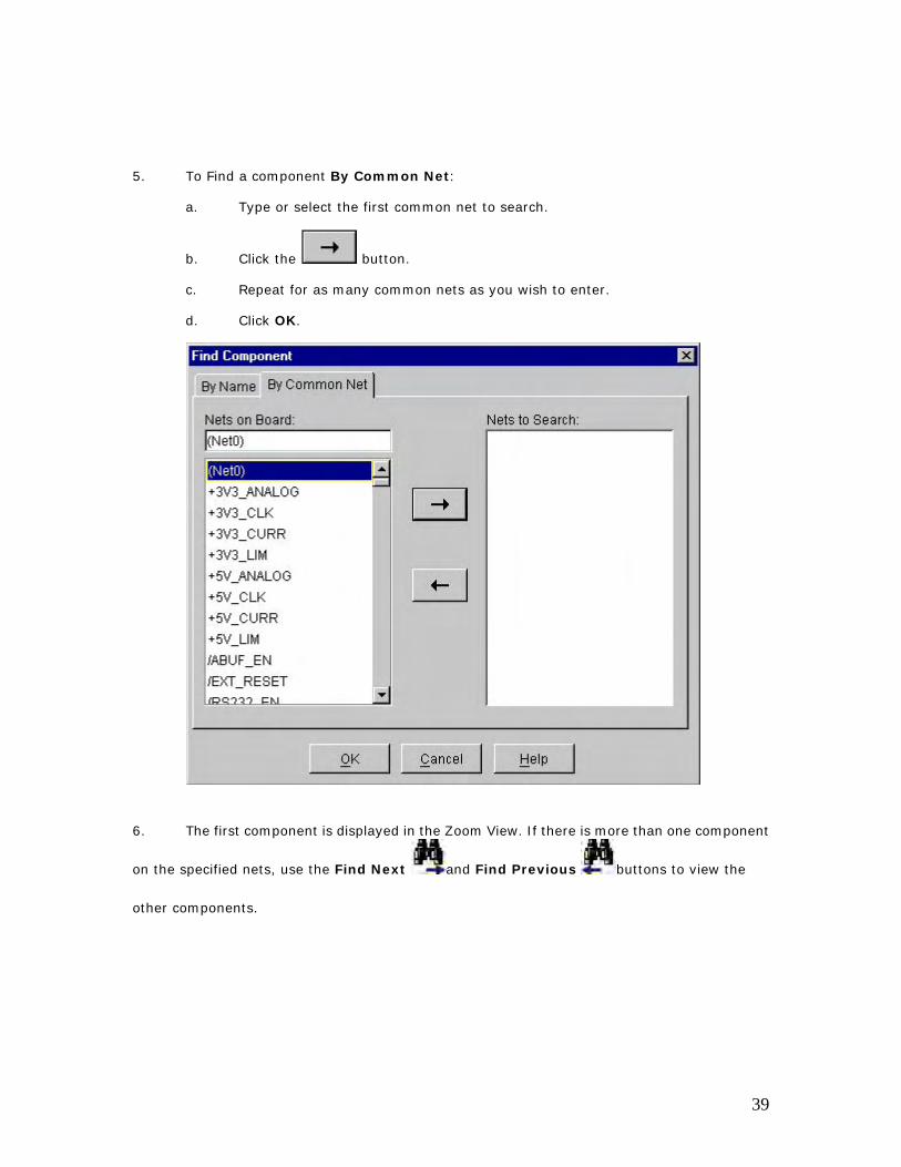
5. To Find a component By Common Net:
a. Type or select the first common net to search.
b. Click the button.
c. Repeat for as many common nets as you wish to enter.
d. Click OK.
6. The first component is displayed in the Zoom View. If there is more than one component
on the specified nets, use the Find Next and Find Previous buttons to view the
other components.
39
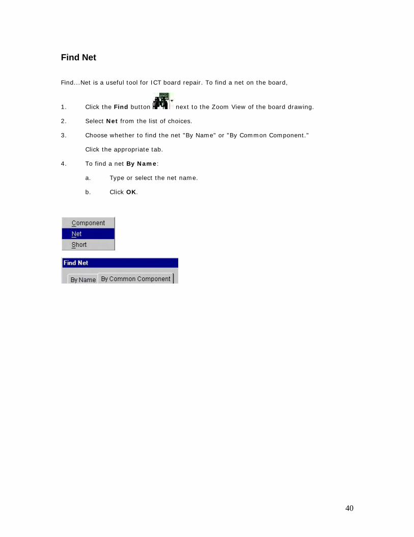
Find Net
Find...Net is a useful tool for ICT board repair. To find a net on the board,
1. Click the Find button next to the Zoom View of the board drawing.
2. Select Net from the list of choices.
3. Choose whether to find the net "By Name" or "By Common Component."
Click the appropriate tab.
4. To find a net By Name:
a. Type or select the net name.
b. Click OK.
40
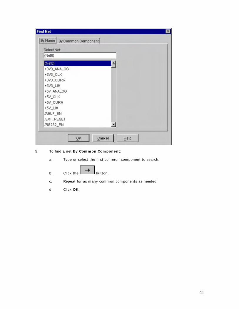
5. To find a net By Common Component:
a. Type or select the first common component to search.
b. Click the button.
c. Repeat for as many common components as needed.
d. Click OK.
41
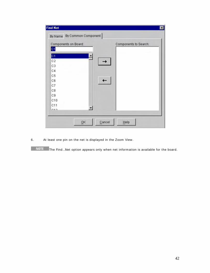
6. At least one pin on the net is displayed in the Zoom View.
The Find…Net option appears only when net information is available for the board.
42
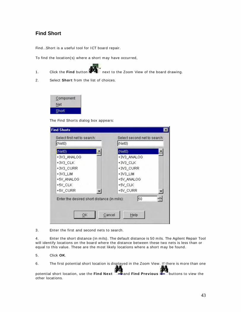
Find Short
Find…Short is a useful tool for ICT board repair.
To find the location(s) where a short may have occurred,
1. Click the Find button next to the Zoom View of the board drawing.
2. Select Short from the list of choices.
The Find Shorts dialog box appears:
3. Enter the first and second nets to search.
4. Enter the short distance (in mils). The default distance is 50 mils. The Agilent Repair Tool will identify locations on the board where the distance between these two nets is less than or equal to this value. These are the most likely locations where a short may be found.
5. Click OK.
6. The first potential short location is displayed in the Zoom View. If there is more than one
potential short location, use the Find Next and Find Previous buttons to view the other locations.
43

The Find…Short option appears only when net information is available for the board.
44

Clear Highlights To clear the highlighted items in the Zoom View of the board drawing, click the Clear
Highlights button . This will clear any highlights that resulted from clicking on components, pins, traces, or from Find…Shorts, Nets, or Components.
Keyboard Shortcut: Ctrl+H
45
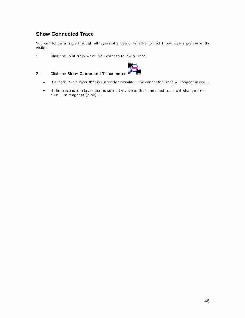
Show Connected Trace You can follow a trace through all layers of a board, whether or not those layers are currently visible.
1. Click the joint from which you want to follow a trace.
2. Click the Show Connected Trace button
• If a trace is in a layer that is currently "invisible," the connected trace will appear in red …
• If the trace is in a layer that is currently visible, the connected trace will change from blue … to magenta (pink) ….
46
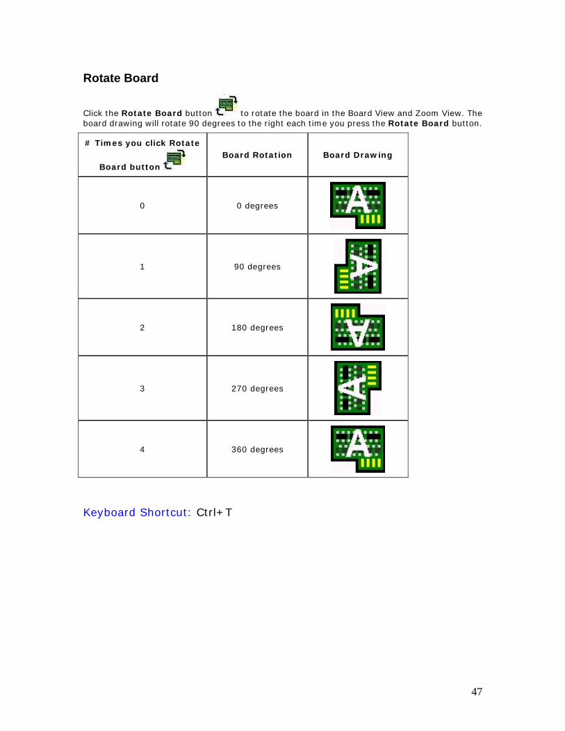
Rotate Board
Click the Rotate Board button to rotate the board in the Board View and Zoom View. The board drawing will rotate 90 degrees to the right each time you press the Rotate Board button.
# Times you click Rotate
Board button Board Rotation Board Drawing
0 0 degrees
1 90 degrees
2 180 degrees
3 270 degrees
4 360 degrees
Keyboard Shortcut: Ctrl+T
47
Zoom In, Zoom Out
Click the Zoom In button to zoom in on the board drawing or the defect image for a closer view.
Click the Zoom Out button to zoom out from the board drawing or the defect image for
a less-detailed view.
Keyboard Shortcuts:
Zoom In on Board Drawing: Ctrl+=
Zoom Out from Board Drawing:
Ctrl+-Zoom In on Image: Ctrl+Shift+=
Zoom Out from Image: Ctrl+Shift+-
48

Zoom Full Board
Click the Zoom Full Board button to view the full board in the Zoom View.
Keyboard Shortcut: Alt+Q
49
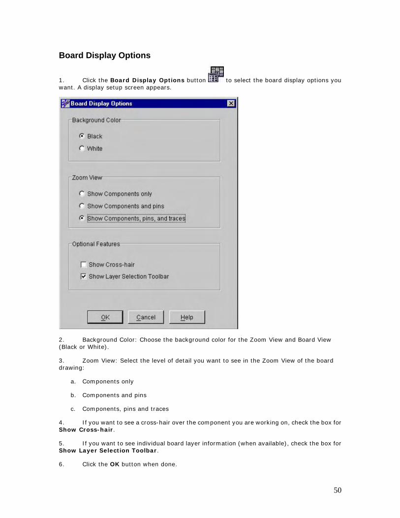
Board Display Options
1. Click the Board Display Options button to select the board display options you want. A display setup screen appears.
2. Background Color: Choose the background color for the Zoom View and Board View (Black or White).
3. Zoom View: Select the level of detail you want to see in the Zoom View of the board drawing:
a. Components only
b. Components and pins
c. Components, pins and traces
4. If you want to see a cross-hair over the component you are working on, check the box for Show Cross-hair.
5. If you want to see individual board layer information (when available), check the box for Show Layer Selection Toolbar.
6. Click the OK button when done.
50

51

View Top Side of Board
Click the View Board Top button to view the top side of the board.
Keyboard Shortcut: Ctrl+1
52

View Bottom Side of Board
Click the View Board Bottom button to view the bottom side of the board.
Keyboard Shortcut: Ctrl+2
53

View Both Sides of Board
Click the View Both Sides of Board button to view components on both sides of the board. The components on the side of the board you were previously looking at remain in color. The components on the opposite side of the board are outlined in gray.
Keyboard Shortcut: Ctrl+3
54
Find Connected Items
When a defect is highlighted in the Defect Table, click the Find Connected Items button
to see devices that are electrically connected to the selected pin or via. After you press the Find
Connected Items button, you may use the Find Previous and Find Next buttons
to step through each connected item.
Keyboard Shortcuts:
Find Connected Items: Ctrl+4 Find Previous: Ctrl+5 Find Next: Ctrl+6
55
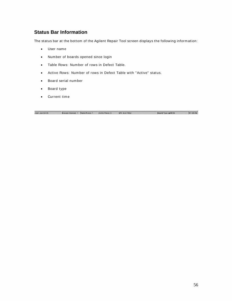
Status Bar Information The status bar at the bottom of the Agilent Repair Tool screen displays the following information:
• User name
• Number of boards opened since login
• Table Rows: Number of rows in Defect Table.
• Active Rows: Number of rows in Defect Table with "Active" status.
• Board serial number
• Board type
• Current time
56
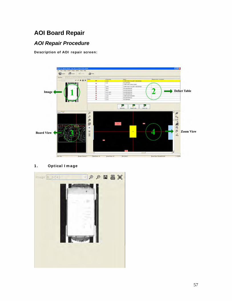
AOI Board Repair AOI Repair Procedure Description of AOI repair screen:
1. Optical Image
57
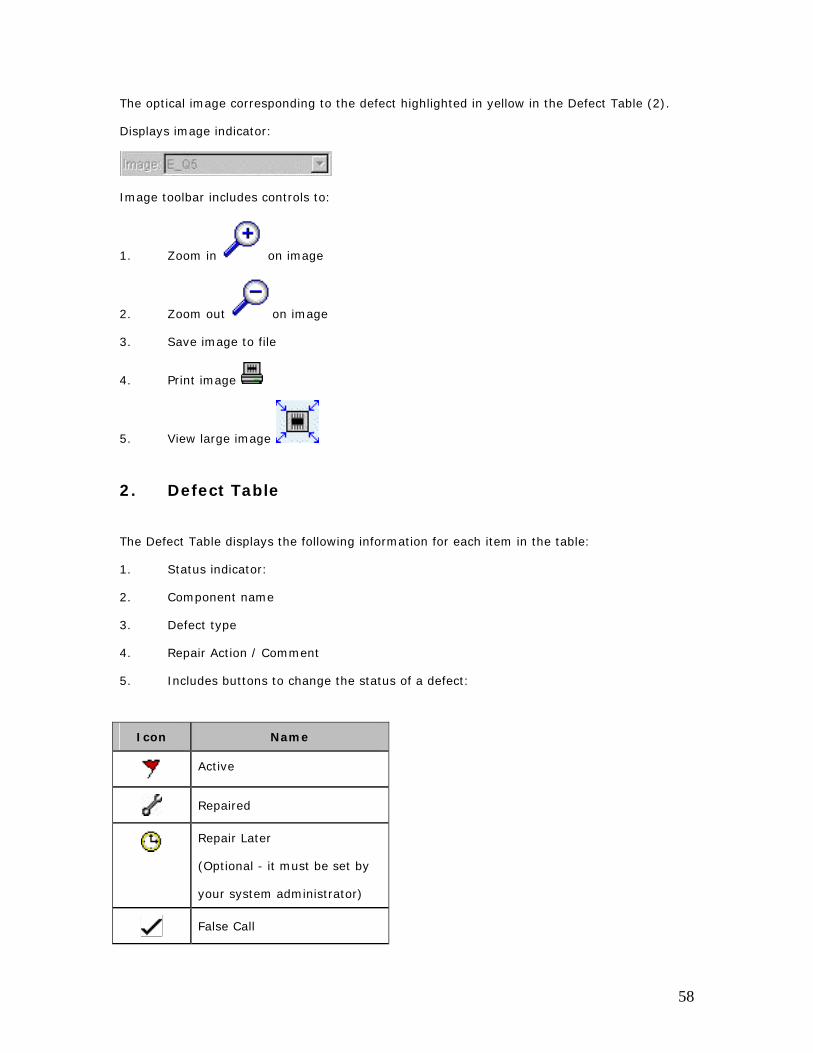
The optical image corresponding to the defect highlighted in yellow in the Defect Table (2).
Displays image indicator:
Image toolbar includes controls to:
1. Zoom in on image
2. Zoom out on image
3. Save image to file
4. Print image
5. View large image
2. Defect Table
The Defect Table displays the following information for each item in the table:
1. Status indicator:
2. Component name
3. Defect type
4. Repair Action / Comment
5. Includes buttons to change the status of a defect:
Icon Name
Active
Repaired
Repair Later
(Optional - it must be set by
your system administrator)
False Call
58
Variation OK
(Optional - it must be set by
your system administrator)
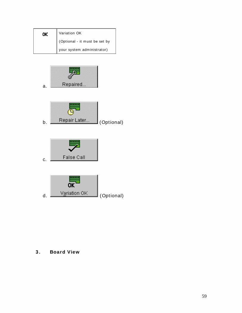
a.
b. (Optional)
c.
d. (Optional)
3. Board View
59
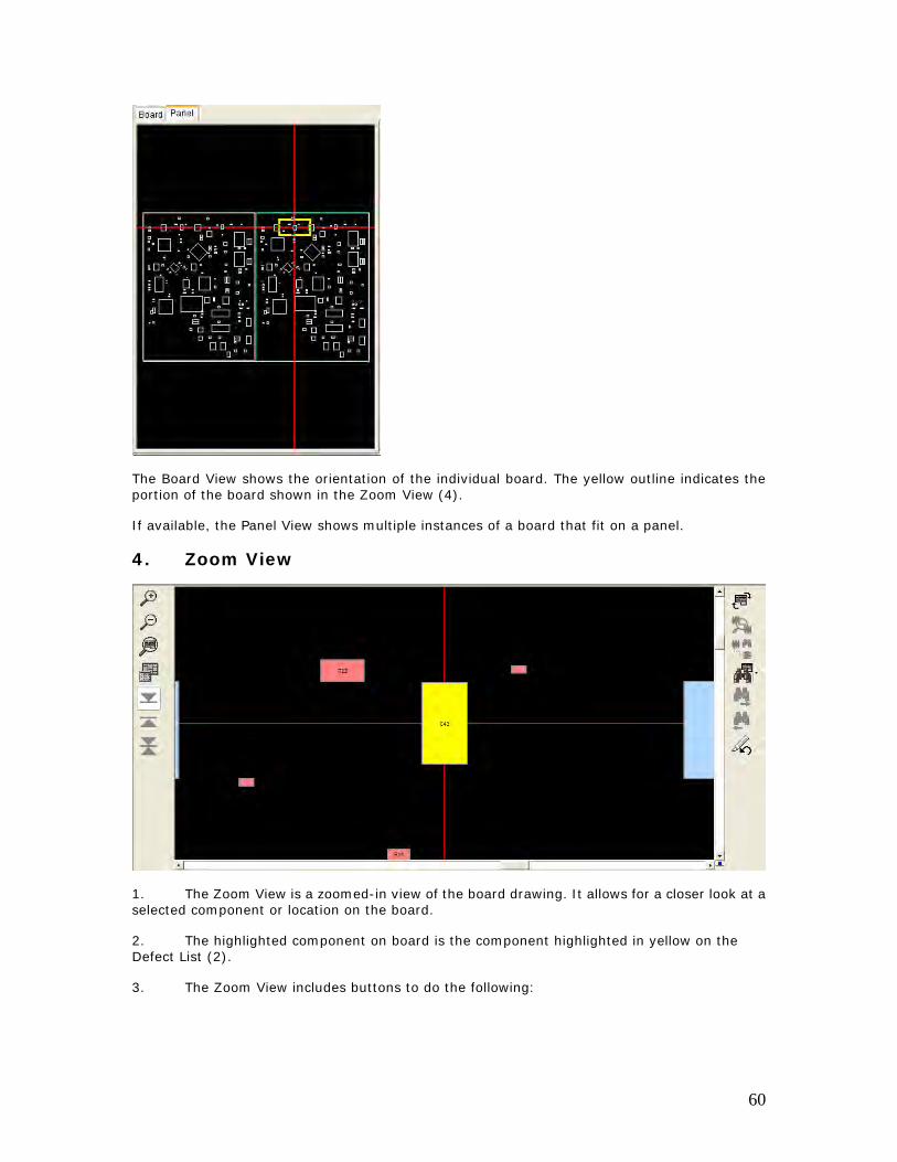
The Board View shows the orientation of the individual board. The yellow outline indicates the portion of the board shown in the Zoom View (4).
If available, the Panel View shows multiple instances of a board that fit on a panel.
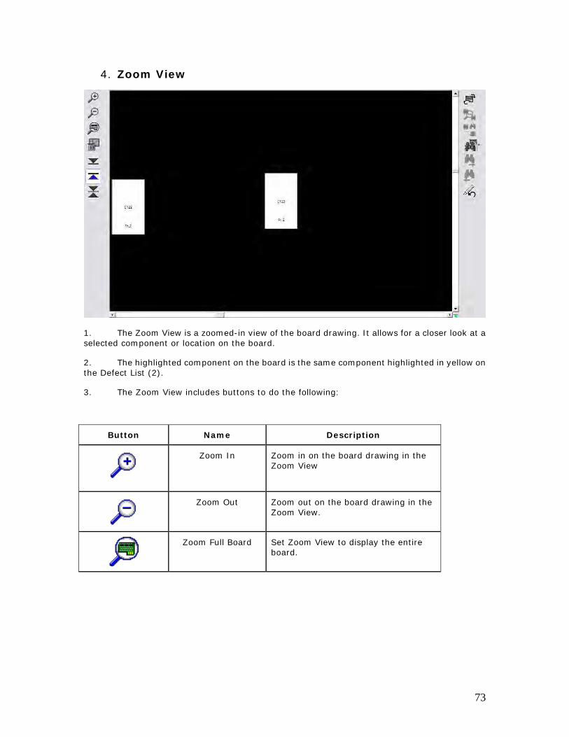
4. Zoom View
1. The Zoom View is a zoomed-in view of the board drawing. It allows for a closer look at a selected component or location on the board.
2. The highlighted component on board is the component highlighted in yellow on the Defect List (2).
3. The Zoom View includes buttons to do the following:
60
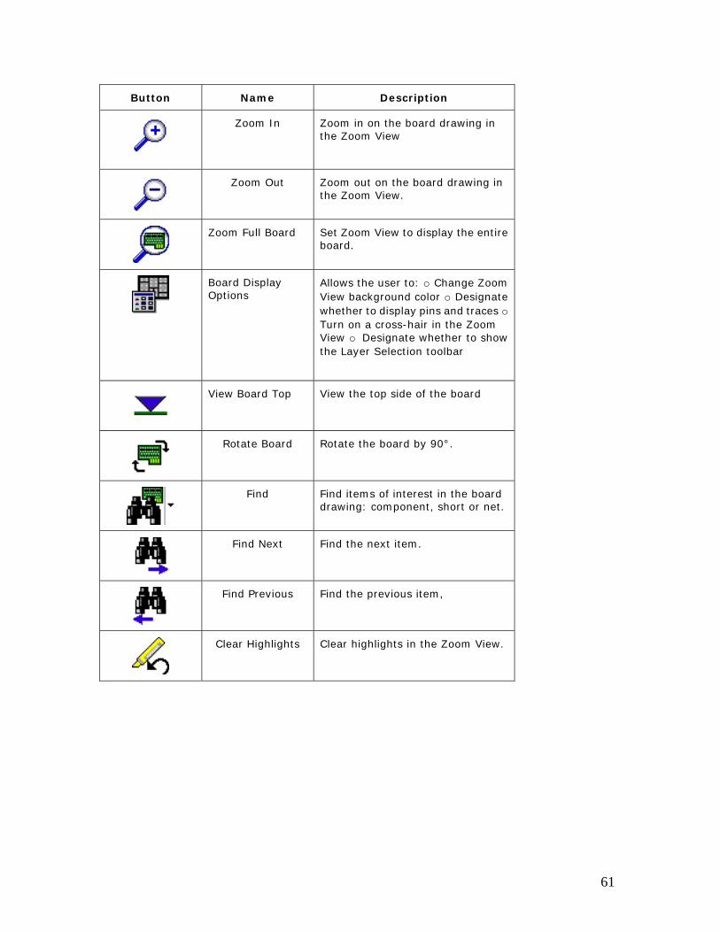
Button Name Description
Zoom In Zoom in on the board drawing in the Zoom View
Zoom Out Zoom out on the board drawing in the Zoom View.
Zoom Full Board Set Zoom View to display the entire board.
Board Display Options
Allows the user to: o Change Zoom View background color o Designate whether to display pins and traces o Turn on a cross-hair in the Zoom View o Designate whether to show the Layer Selection toolbar
View Board Top View the top side of the board
Rotate Board Rotate the board by 90°.
Find Find items of interest in the board drawing: component, short or net.
Find Next Find the next item.
Find Previous Find the previous item,
Clear Highlights Clear highlights in the Zoom View.
61
Processing an AOI_SJ/AOI_SP defect 1. Open a board. (See Open a Board for more information.)
2. Look at the first item in the Defect Table (2).
3. Notice the Image (1) corresponding to this item.
4. Find the component in the Board View (3) or Zoom View (4).
Find the yellow outline in the Board View (3). This indicates the portion of the board that is displayed in the Zoom View (4).
Find the highlighted component in the Zoom View (4). This will be the same component as is highlighted in yellow in the Defect Table (2).
If a group of pins is circled in the Zoom View, the AOI inspection system determined that the problem is anywhere in that group. You will need to investigate further to find out the source of the fault.
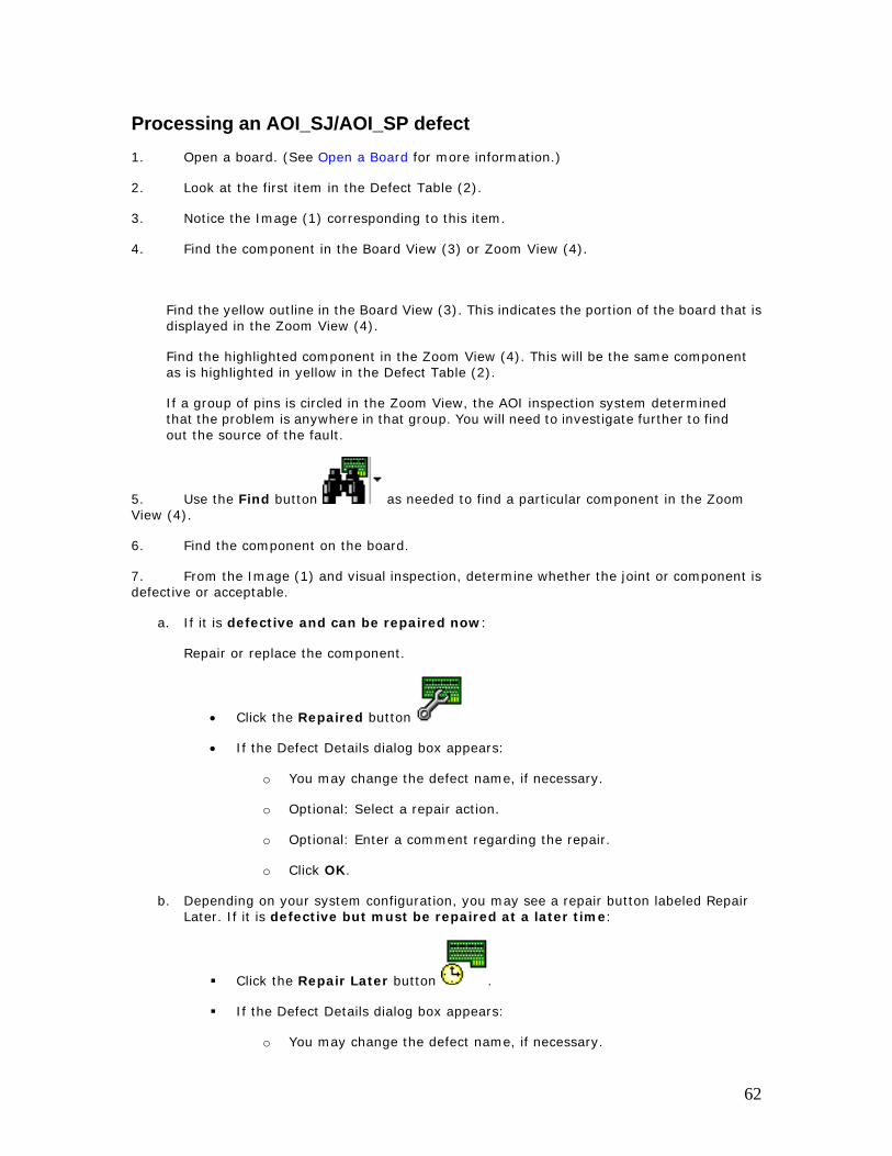
5. Use the Find button as needed to find a particular component in the Zoom View (4).
6. Find the component on the board.
7. From the Image (1) and visual inspection, determine whether the joint or component is defective or acceptable.
a. If it is defective and can be repaired now:
Repair or replace the component.
• Click the Repaired button
• If the Defect Details dialog box appears:
o You may change the defect name, if necessary.
o Optional: Select a repair action.
o Optional: Enter a comment regarding the repair.
o Click OK.
b. Depending on your system configuration, you may see a repair button labeled Repair Later. If it is defective but must be repaired at a later time:
Click the Repair Later button .
If the Defect Details dialog box appears:
o You may change the defect name, if necessary.
62
o Optional: Select a repair action.
o Optional: Enter a comment regarding the reason for repairing later.
o Click OK.
c. If the joint or component is good:
• Click the False Call button
d. Depending on your system configuration, you may see a repair button labeled Variation OK. If the condition of the joint or component varies slightly from the ideal, but is still OK:
• Click the Variation OK button
• If the Defect Details dialog box appears:
o You may change the defect name, if necessary.
o Optional: Enter a comment regarding why this is acceptable.
o Click OK.
8. Repeat until you have addressed all items in the Defect Table (2).
9. When the dialog box indicates that there are no more active defects on this board and asks, Do you want to open another board?
• Click OK to open another board, or
• Click Cancel to go back to the repair screen.
10. Follow your company’s procedure regarding retesting the board.
63
Optical Image
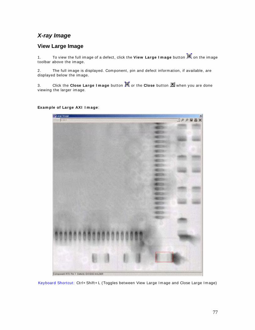
View Large Image
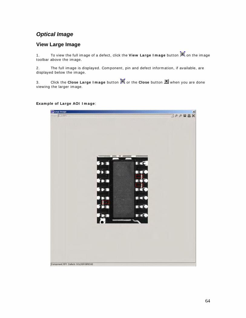
1. To view the full image of a defect, click the View Large Image button on the image toolbar above the image.
2. The full image is displayed. Component, pin and defect information, if available, are displayed below the image.
3. Click the Close Large Image button or the Close button when you are done viewing the larger image.
Example of Large AOI Image:
64
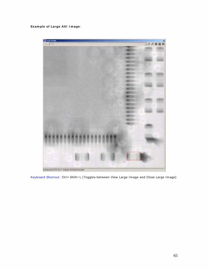
Example of Large AXI Image:
Keyboard Shortcut: Ctrl+Shift+L (Toggles between View Large Image and Close Large Image)
65
Print Image
To print the image that is currently displayed: Click the Print Image button on the image
toolbar above the image.
Keyboard Shortcut: Ctrl+Shift+P
66
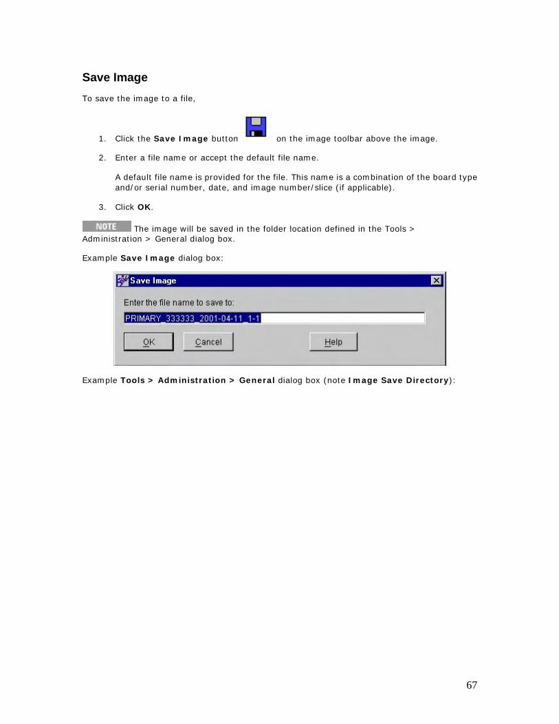
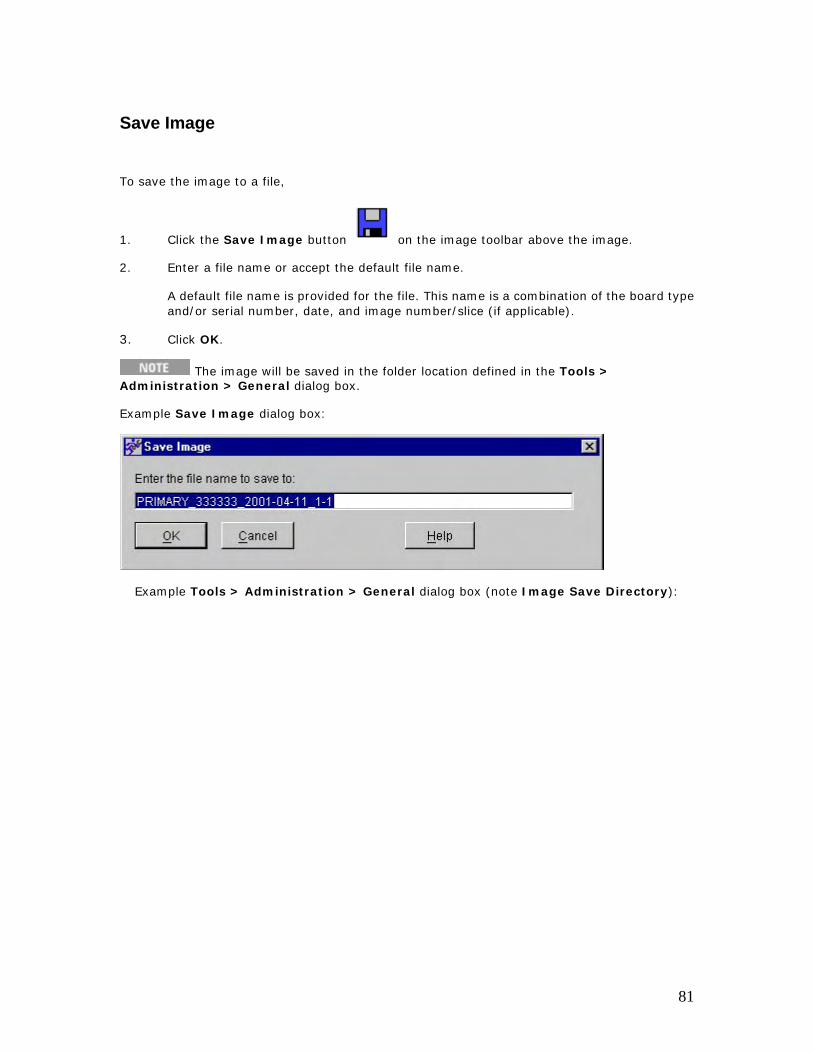
Save Image To save the image to a file,
1. Click the Save Image button on the image toolbar above the image.
2. Enter a file name or accept the default file name.
A default file name is provided for the file. This name is a combination of the board type and/or serial number, date, and image number/slice (if applicable).
3. Click OK.
The image will be saved in the folder location defined in the Tools > Administration > General dialog box.
Example Save Image dialog box:
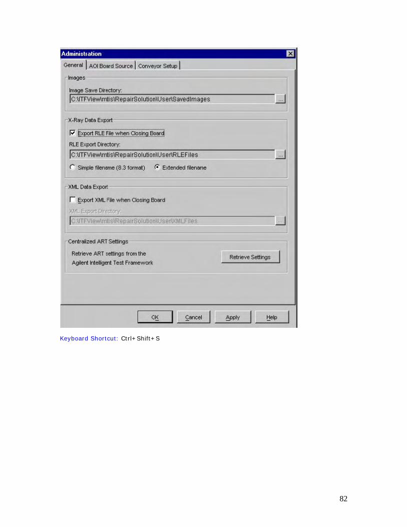
Example Tools > Administration > General dialog box (note Image Save Directory):
67
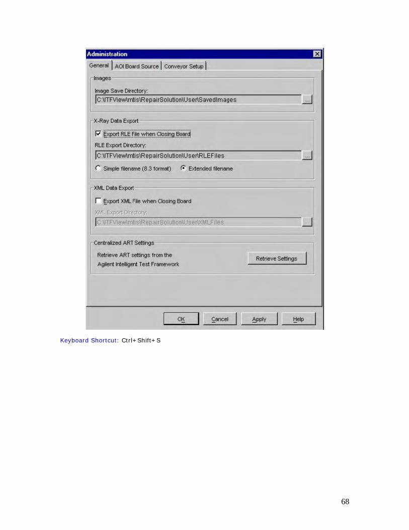
Keyboard Shortcut: Ctrl+Shift+S
68
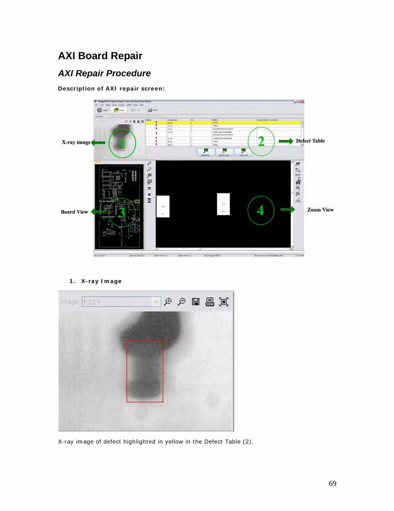
AXI Board Repair AXI Repair Procedure Description of AXI repair screen:
1. X-ray Image
X-ray image of defect highlighted in yellow in the Defect Table (2).
69
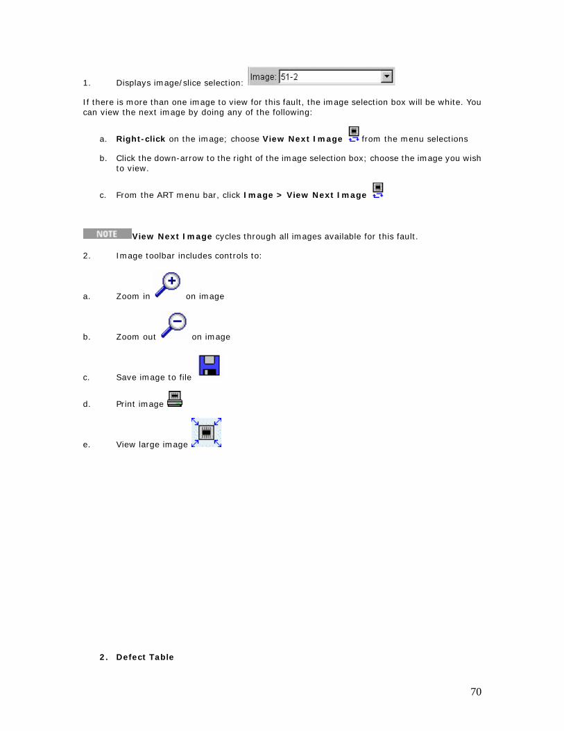
1. Displays image/slice selection:
If there is more than one image to view for this fault, the image selection box will be white. You can view the next image by doing any of the following:
a. Right-click on the image; choose View Next Image from the menu selections
b. Click the down-arrow to the right of the image selection box; choose the image you wish to view.
c. From the ART menu bar, click Image > View Next Image
View Next Image cycles through all images available for this fault.
2. Image toolbar includes controls to:
a. Zoom in on image
b. Zoom out on image
c. Save image to file
d. Print image
e. View large image
2. Defect Table
70
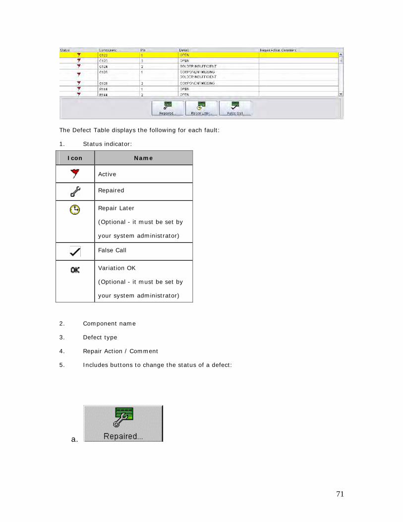
The Defect Table displays the following for each fault:
1. Status indicator:
Icon Name
Active
Repaired
Repair Later
(Optional - it must be set by
your system administrator)
False Call
Variation OK
(Optional - it must be set by
your system administrator)
2. Component name
3. Defect type
4. Repair Action / Comment
5. Includes buttons to change the status of a defect:
a.
71
b. (Optional)
c.
d. (Optional)
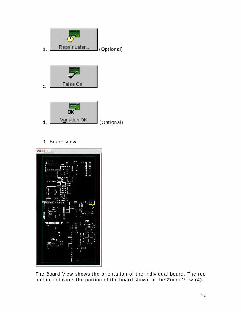
3. Board View
The Board View shows the orientation of the individual board. The red outline indicates the portion of the board shown in the Zoom View (4).
72
4. Zoom View
1. The Zoom View is a zoomed-in view of the board drawing. It allows for a closer look at a selected component or location on the board.
2. The highlighted component on the board is the same component highlighted in yellow on the Defect List (2).
3. The Zoom View includes buttons to do the following:
Button Name Description
Zoom In Zoom in on the board drawing in the Zoom View
Zoom Out Zoom out on the board drawing in the Zoom View.
Zoom Full Board Set Zoom View to display the entire board.
73
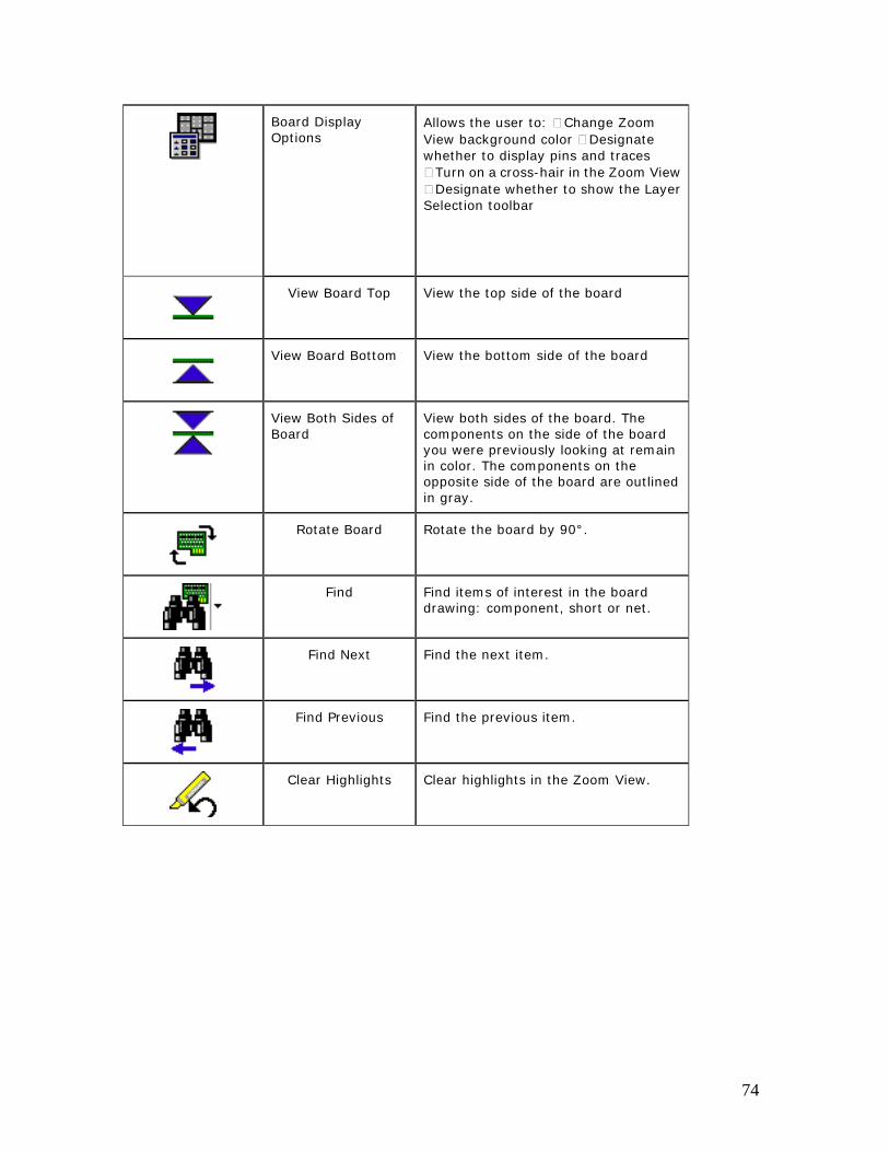
Board Display Options
Allows the user to: Change Zoom View background color Designate whether to display pins and traces
Turn on a cross-hair in the Zoom View Designate whether to show the Layer
Selection toolbar
View Board Top View the top side of the board
View Board Bottom View the bottom side of the board
View Both Sides of Board
View both sides of the board. The components on the side of the board you were previously looking at remain in color. The components on the opposite side of the board are outlined in gray.
Rotate Board Rotate the board by 90°.
Find Find items of interest in the board drawing: component, short or net.
Find Next Find the next item.
Find Previous Find the previous item.
Clear Highlights Clear highlights in the Zoom View.
74
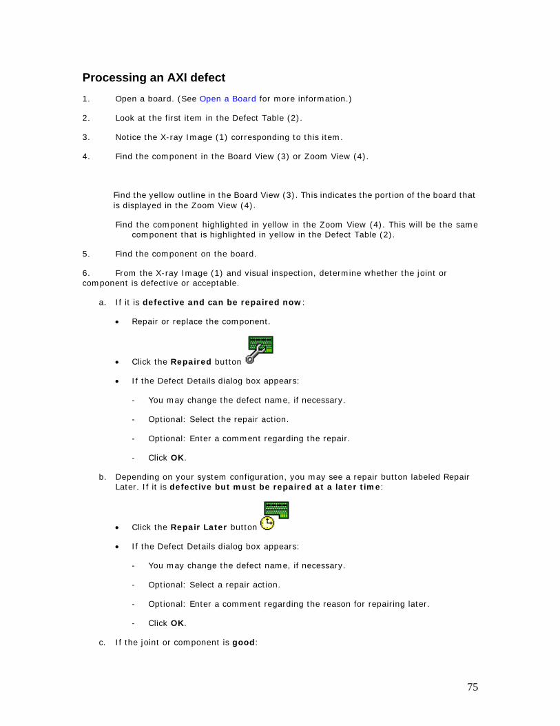
Processing an AXI defect 1. Open a board. (See Open a Board for more information.)
2. Look at the first item in the Defect Table (2).
3. Notice the X-ray Image (1) corresponding to this item.
4. Find the component in the Board View (3) or Zoom View (4).
Find the yellow outline in the Board View (3). This indicates the portion of the board that is displayed in the Zoom View (4).
Find the component highlighted in yellow in the Zoom View (4). This will be the same component that is highlighted in yellow in the Defect Table (2).
5. Find the component on the board.
6. From the X-ray Image (1) and visual inspection, determine whether the joint or component is defective or acceptable.
a. If it is defective and can be repaired now:
• Repair or replace the component.
• Click the Repaired button
• If the Defect Details dialog box appears:
- You may change the defect name, if necessary.
- Optional: Select the repair action.
- Optional: Enter a comment regarding the repair.
- Click OK.
b. Depending on your system configuration, you may see a repair button labeled Repair Later. If it is defective but must be repaired at a later time:
• Click the Repair Later button
• If the Defect Details dialog box appears:
- You may change the defect name, if necessary.
- Optional: Select a repair action.
- Optional: Enter a comment regarding the reason for repairing later.
- Click OK.
c. If the joint or component is good:
75
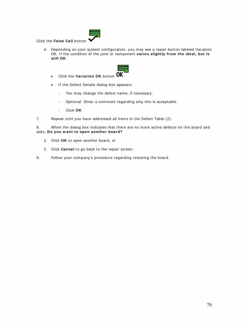
Click the False Call button
d. Depending on your system configuration, you may see a repair button labeled Variation OK. If the condition of the joint or component varies slightly from the ideal, but is still OK:
• Click the Variation OK button
• If the Defect Details dialog box appears:
- You may change the defect name, if necessary.
- Optional: Enter a comment regarding why this is acceptable.
- Click OK.
7. Repeat until you have addressed all items in the Defect Table (2).
8. When the dialog box indicates that there are no more active defects on this board and asks, Do you want to open another board?
1. Click OK to open another board, or
2. Click Cancel to go back to the repair screen.
9. Follow your company’s procedure regarding retesting the board.
76
X-ray Image
View Large Image
1. To view the full image of a defect, click the View Large Image button on the image toolbar above the image.
2. The full image is displayed. Component, pin and defect information, if available, are displayed below the image.
3. Click the Close Large Image button or the Close button when you are done viewing the larger image.
Example of Large AXI Image:
Keyboard Shortcut: Ctrl+Shift+L (Toggles between View Large Image and Close Large Image)
77
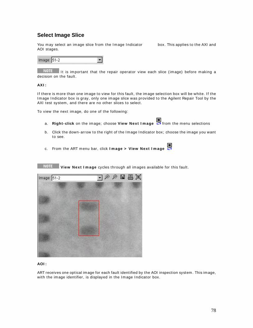
Select Image Slice You may select an image slice from the Image Indicator box. This applies to the AXI and AOI stages.
It is important that the repair operator view each slice (image) before making a decision on the fault.
AXI:
If there is more than one image to view for this fault, the image selection box will be white. If the Image Indicator box is gray, only one image slice was provided to the Agilent Repair Tool by the AXI test system, and there are no other slices to select.
To view the next image, do one of the following:
a. Right-click on the image; choose View Next Image from the menu selections
b. Click the down-arrow to the right of the Image Indicator box; choose the image you want to see.
c. From the ART menu bar, click Image > View Next Image
View Next Image cycles through all images available for this fault.
AOI:
ART receives one optical image for each fault identified by the AOI inspection system. This image, with the image identifier, is displayed in the Image Indicator box.
78
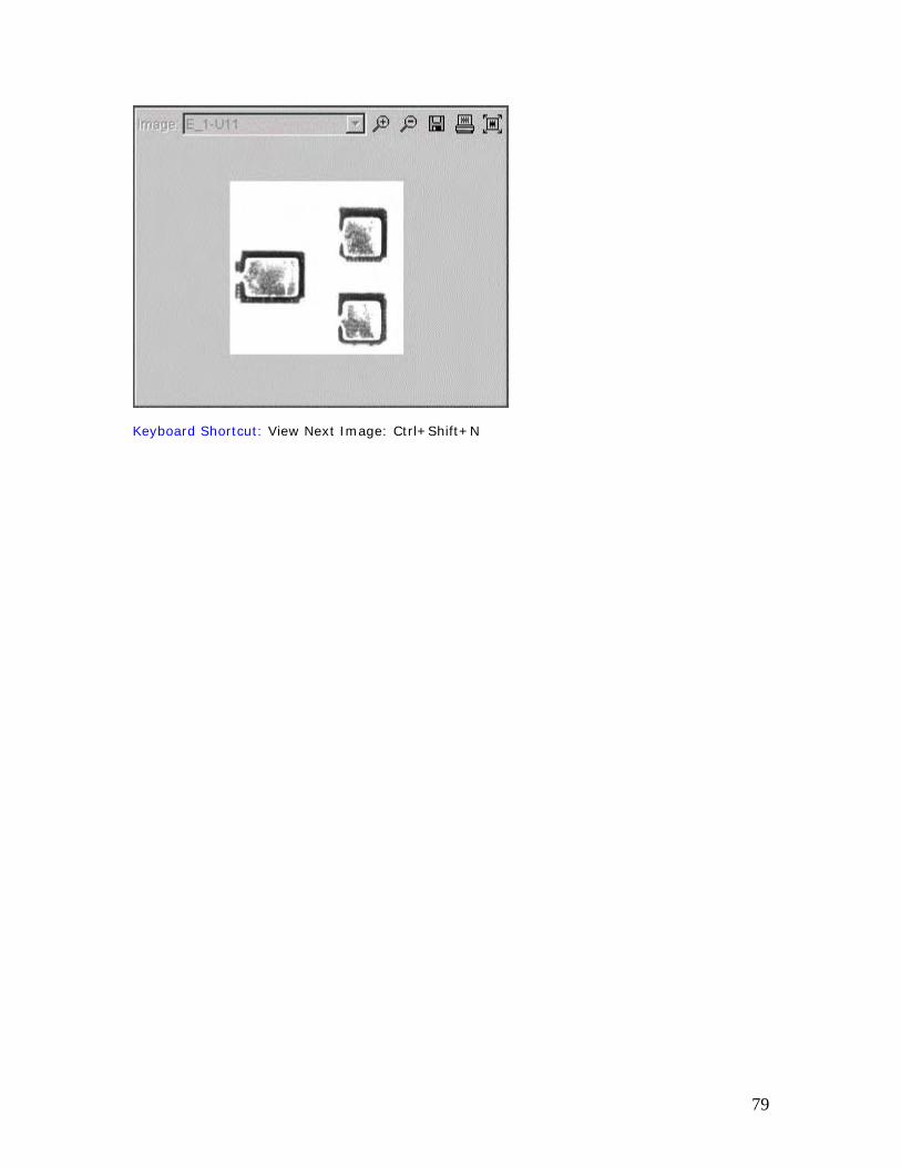
Keyboard Shortcut: View Next Image: Ctrl+Shift+N
79
Print Image
To print the image that is currently displayed: Click the Print Image button on the image
toolbar above the image.
Keyboard Shortcut: Ctrl+Shift+P
80
Save Image
To save the image to a file,
1. Click the Save Image button on the image toolbar above the image.
2. Enter a file name or accept the default file name.
A default file name is provided for the file. This name is a combination of the board type and/or serial number, date, and image number/slice (if applicable).
3. Click OK.
The image will be saved in the folder location defined in the Tools > Administration > General dialog box.
Example Save Image dialog box:
Example Tools > Administration > General dialog box (note Image Save Directory):
81
Keyboard Shortcut: Ctrl+Shift+S
82
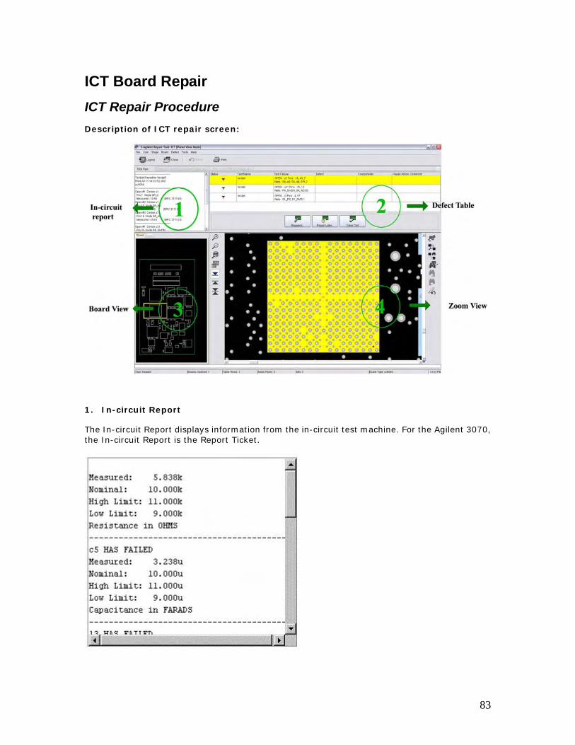
ICT Board Repair ICT Repair Procedure Description of ICT repair screen:
1. In-circuit Report
The In-circuit Report displays information from the in-circuit test machine. For the Agilent 3070, the In-circuit Report is the Report Ticket.
83
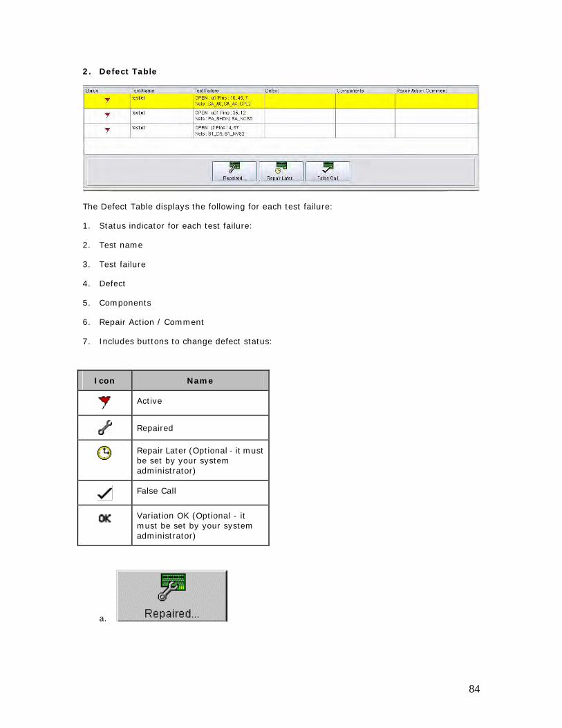
2. Defect Table
The Defect Table displays the following for each test failure:
1. Status indicator for each test failure:
2. Test name
3. Test failure
4. Defect
5. Components
6. Repair Action / Comment
7. Includes buttons to change defect status:
Icon Name
Active
Repaired
Repair Later (Optional - it must be set by your system administrator)
False Call
Variation OK (Optional - it must be set by your system administrator)
a.
84
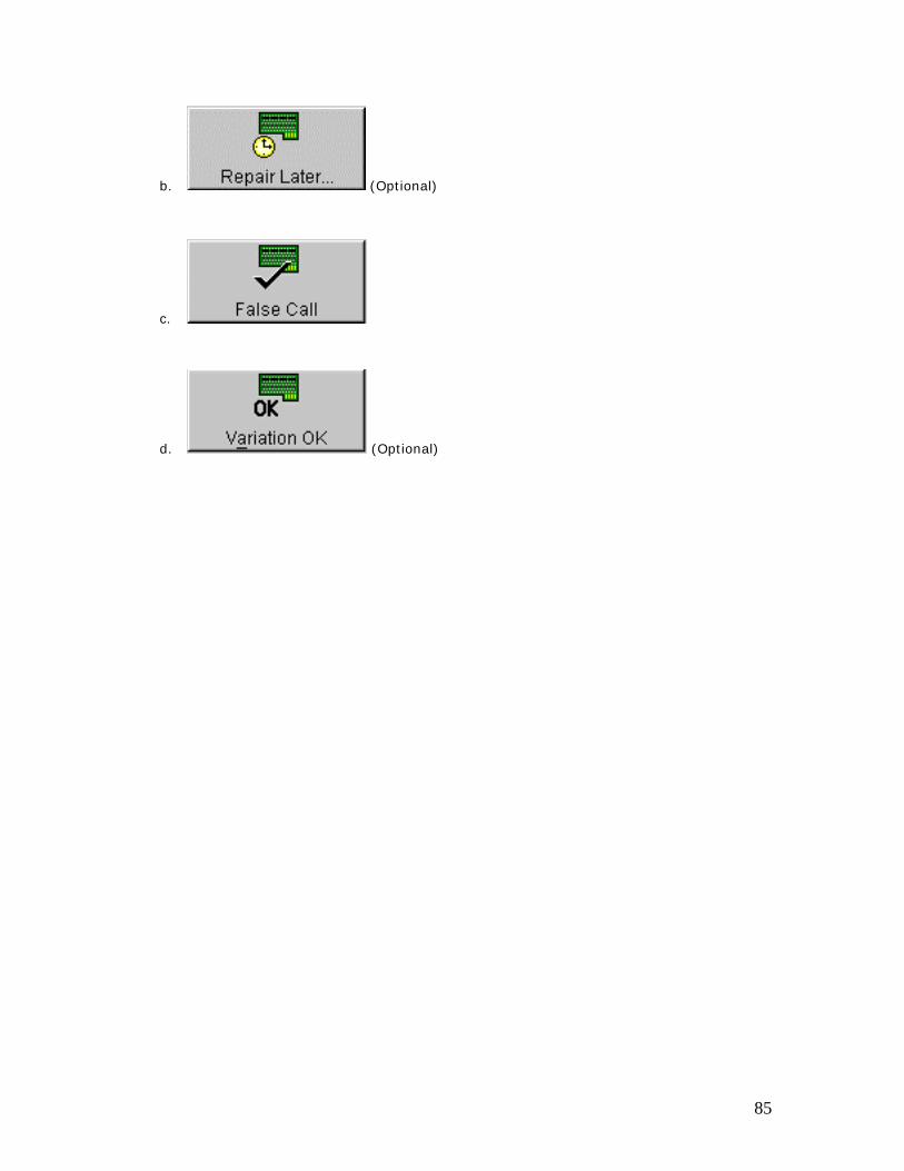
b. (Optional)
c.
d. (Optional)
85
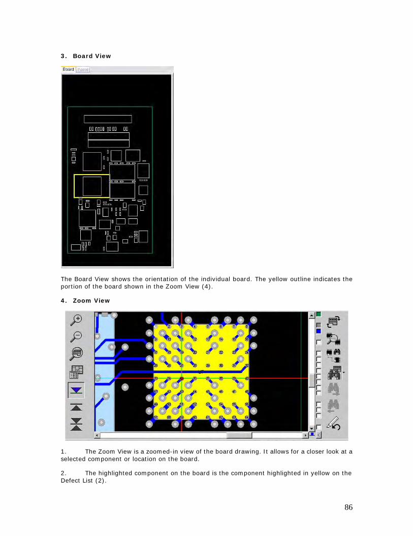
3. Board View
The Board View shows the orientation of the individual board. The yellow outline indicates the portion of the board shown in the Zoom View (4).
4. Zoom View
1. The Zoom View is a zoomed-in view of the board drawing. It allows for a closer look at a selected component or location on the board.
2. The highlighted component on the board is the component highlighted in yellow on the Defect List (2).
86
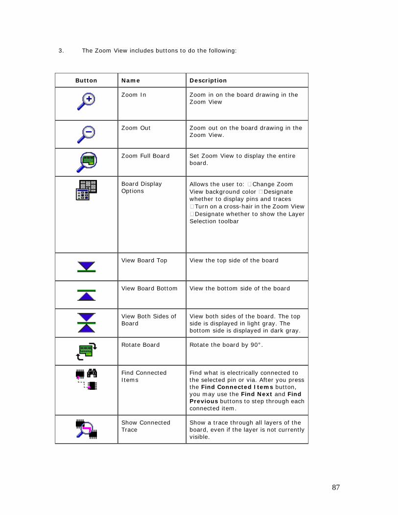
3. The Zoom View includes buttons to do the following:
Button Name Description
Zoom In Zoom in on the board drawing in the Zoom View
Zoom Out Zoom out on the board drawing in the Zoom View.
Zoom Full Board Set Zoom View to display the entire board.
Board Display Options
Allows the user to: Change Zoom View background color Designate whether to display pins and traces
Turn on a cross-hair in the Zoom View Designate whether to show the Layer
Selection toolbar
View Board Top View the top side of the board
View Board Bottom View the bottom side of the board
View Both Sides of Board
View both sides of the board. The top side is displayed in light gray. The bottom side is displayed in dark gray.
Rotate Board Rotate the board by 90°.
Find Connected Items
Find what is electrically connected to the selected pin or via. After you press the Find Connected Items button, you may use the Find Next and Find Previous buttons to step through each connected item.
Show Connected Trace
Show a trace through all layers of the board, even if the layer is not currently visible.
87
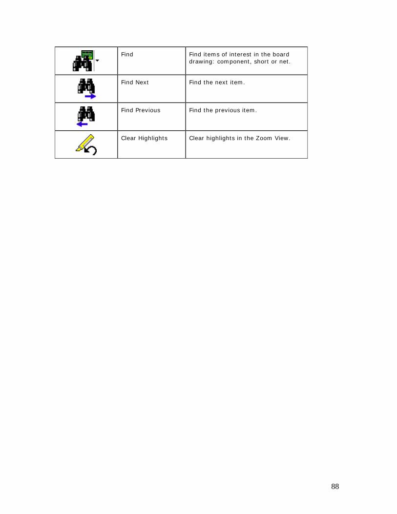
Find Find items of interest in the board drawing: component, short or net.
Find Next Find the next item.
Find Previous Find the previous item.
Clear Highlights Clear highlights in the Zoom View.
88
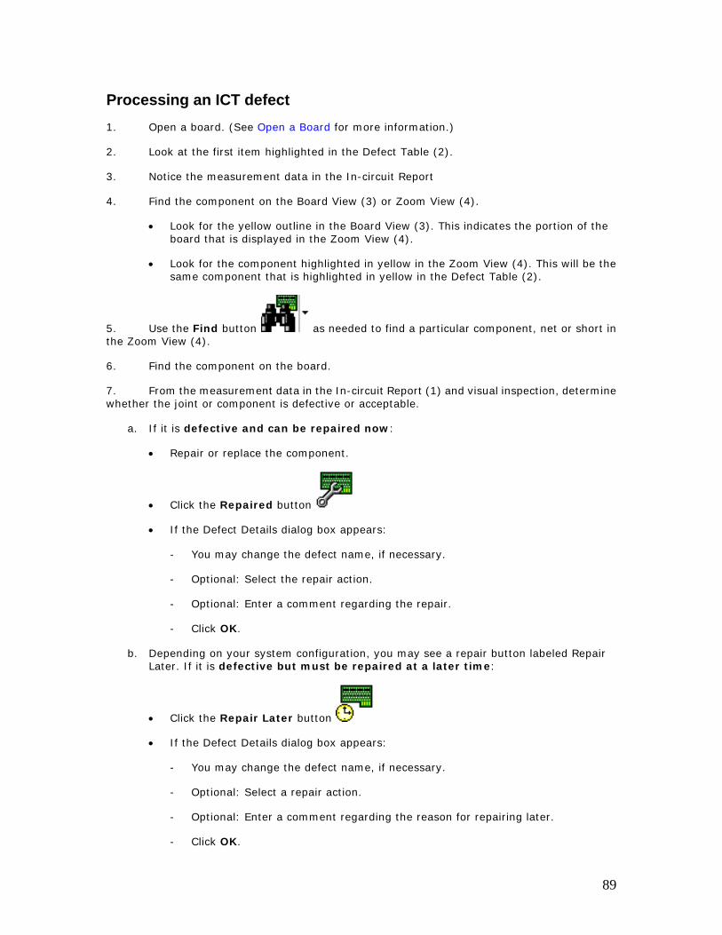
Processing an ICT defect 1. Open a board. (See Open a Board for more information.)
2. Look at the first item highlighted in the Defect Table (2).
3. Notice the measurement data in the In-circuit Report
4. Find the component on the Board View (3) or Zoom View (4).
• Look for the yellow outline in the Board View (3). This indicates the portion of the board that is displayed in the Zoom View (4).
• Look for the component highlighted in yellow in the Zoom View (4). This will be the same component that is highlighted in yellow in the Defect Table (2).
5. Use the Find button as needed to find a particular component, net or short in the Zoom View (4).
6. Find the component on the board.
7. From the measurement data in the In-circuit Report (1) and visual inspection, determine whether the joint or component is defective or acceptable.
a. If it is defective and can be repaired now:
• Repair or replace the component.
• Click the Repaired button
• If the Defect Details dialog box appears:
- You may change the defect name, if necessary.
- Optional: Select the repair action.
- Optional: Enter a comment regarding the repair.
- Click OK.
b. Depending on your system configuration, you may see a repair button labeled Repair Later. If it is defective but must be repaired at a later time:
• Click the Repair Later button
• If the Defect Details dialog box appears:
- You may change the defect name, if necessary.
- Optional: Select a repair action.
- Optional: Enter a comment regarding the reason for repairing later.
- Click OK.
89
c. If the joint or component is good:
• Click the False Call button
d. Depending on your system configuration, you may see a repair button labeled Variation OK. If the condition of the joint or component varies slightly from the ideal, but is still OK:
• Click the Variation OK button
• If the Defect Details dialog box appears:
- You may change the defect name, if necessary.
- Optional: Enter a comment regarding why this is acceptable.
- Click OK.
8. Repeat until you have addressed all faults in the Defect Table (2).
• When the dialog box indicates that there are no more active defects on this board and asks, Do you want to open another board?
• Click OK to open another board
9. Click Cancel to go back to the repair screen.
10. Follow your company’s procedure regarding retesting the board.
90
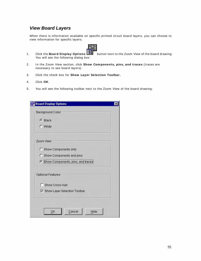
View Board Layers When there is information available on specific printed circuit board layers, you can choose to view information for specific layers.
1. Click the Board Display Options button next to the Zoom View of the board drawing. You will see the following dialog box:
2. In the Zoom View section, click Show Components, pins, and traces (traces are necessary to see board layers).
3. Click the check box for Show Layer Selection Toolbar.
4. Click OK.
5. You will see the following toolbar next to the Zoom View of the board drawing:
91
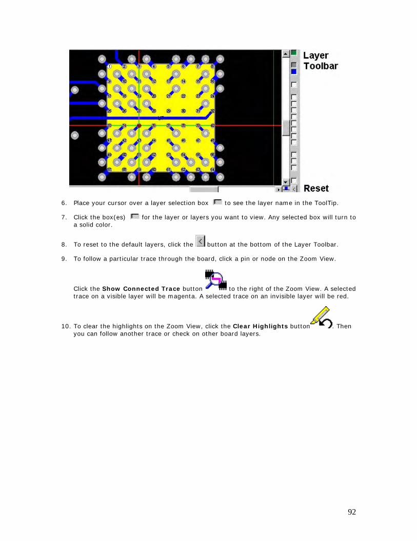
6. Place your cursor over a layer selection box to see the layer name in the ToolTip.
7. Click the box(es) for the layer or layers you want to view. Any selected box will turn to a solid color.
8. To reset to the default layers, click the button at the bottom of the Layer Toolbar.
9. To follow a particular trace through the board, click a pin or node on the Zoom View.
Click the Show Connected Trace button to the right of the Zoom View. A selected trace on a visible layer will be magenta. A selected trace on an invisible layer will be red.
10. To clear the highlights on the Zoom View, click the Clear Highlights button . Then you can follow another trace or check on other board layers.
92
Repair Actions Repaired
1. Press the Repaired button to indicate that a specific pin or component has been repaired.
2. If the Defect Details dialog box appears, you may confirm or change the specific defect for this pin or component. You may also select a repair action and/or enter a comment for this defect in the Defect Details dialog box.
Keyboard Shortcut: Ctrl+R
93
Repair Later The Repair Later button is an optional button. It appears only when your system administrator has set this option in the ITF Administration System.
1. Press the Repair Later button to indicate that a specific pin or component is to be repaired later.
2. If the Defect Details dialog box appears, you may confirm or change the specific defect for this pin or component. You may also select a repair action and/or enter a comment in the Defect Details dialog box to state why the repair is to be done at a later time.
Keyboard Shortcut: Ctrl+L
94
False Call
Press the False Call button to indicate that:
• There is no defect associated with this fault.
• No repair is necessary.
If you are identifying numerous false calls, you should consider examining the test system programs or algorithms. The programs or algorithms may need to be tuned.
Keyboard Shortcut: Ctrl+F
95
Variation OK The Variation OK button is an optional button. It appears only when your system administrator has set this option in the ITF Administration System.
Press the Variation OK button to indicate that:
• The fault is an acceptable deviation from the norm. This is a variation from the ideal, but it is OK.
• No repair is necessary.
Sometimes the placement of a component or the solder on a particular joint will vary slightly from the "ideal" placement or solder, but the resulting placement or solder will still be an acceptable deviation from the norm. In this case, you might choose to mark the component or joint "Variation OK." When an item is marked "Variation OK," no repair is needed, as the component or joint falls in the range of an "acceptable deviation from the norm."
If the Defect Details dialog box appears after you press the Variation OK button, you may e nter a comment to indicate the reason for this status.
Keyboard Shortcut: Ctrl+K
96
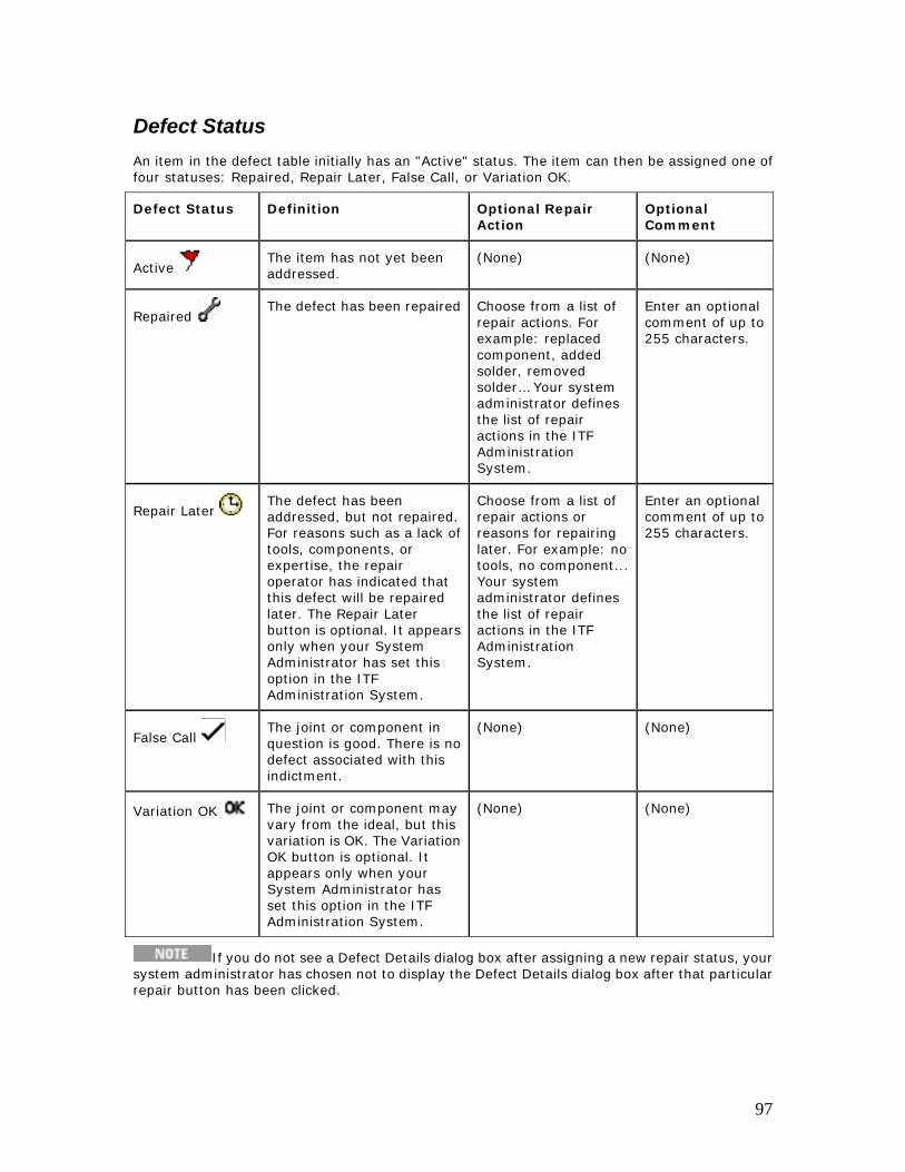
Defect Status An item in the defect table initially has an "Active" status. The item can then be assigned one of four statuses: Repaired, Repair Later, False Call, or Variation OK.
Defect Status Definition Optional Repair Action
Optional Comment
Active The item has not yet been addressed.
(None) (None)
Repaired The defect has been repaired Choose from a list of
repair actions. For example: replaced component, added solder, removed solder… Your system administrator defines the list of repair actions in the ITF Administration System.
Enter an optional comment of up to 255 characters.
Repair Later The defect has been addressed, but not repaired. For reasons such as a lack of tools, components, or expertise, the repair operator has indicated that this defect will be repaired later. The Repair Later button is optional. It appears only when your System Administrator has set this option in the ITF Administration System.
Choose from a list of repair actions or reasons for repairing later. For example: no tools, no component... Your system administrator defines the list of repair actions in the ITF Administration System.
Enter an optional comment of up to 255 characters.
False Call The joint or component in question is good. There is no defect associated with this indictment.
(None) (None)
Variation OK The joint or component may vary from the ideal, but this variation is OK. The Variation OK button is optional. It appears only when your System Administrator has set this option in the ITF Administration System.
(None) (None)
If you do not see a Defect Details dialog box after assigning a new repair status, your system administrator has chosen not to display the Defect Details dialog box after that particular repair button has been clicked.
97
Undo Repair Action
Click the Undo Repair Action button to undo the last repair action you made. The defect will be restored to its previous state. The yellow highlight in the defect table will return to the item that was "undone."
The repair action that is "undone" is always the last repair action. This action is independent of the defect highlighted in the Defect Table.
Keyboard Shortcut: Ctrl+Z
98
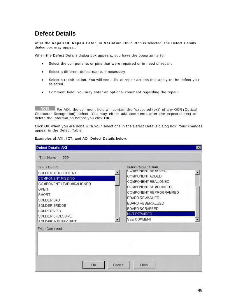
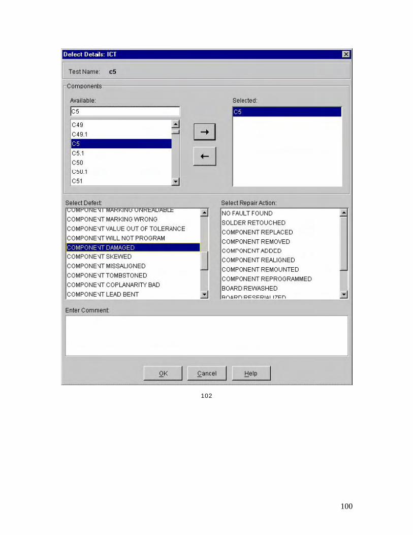
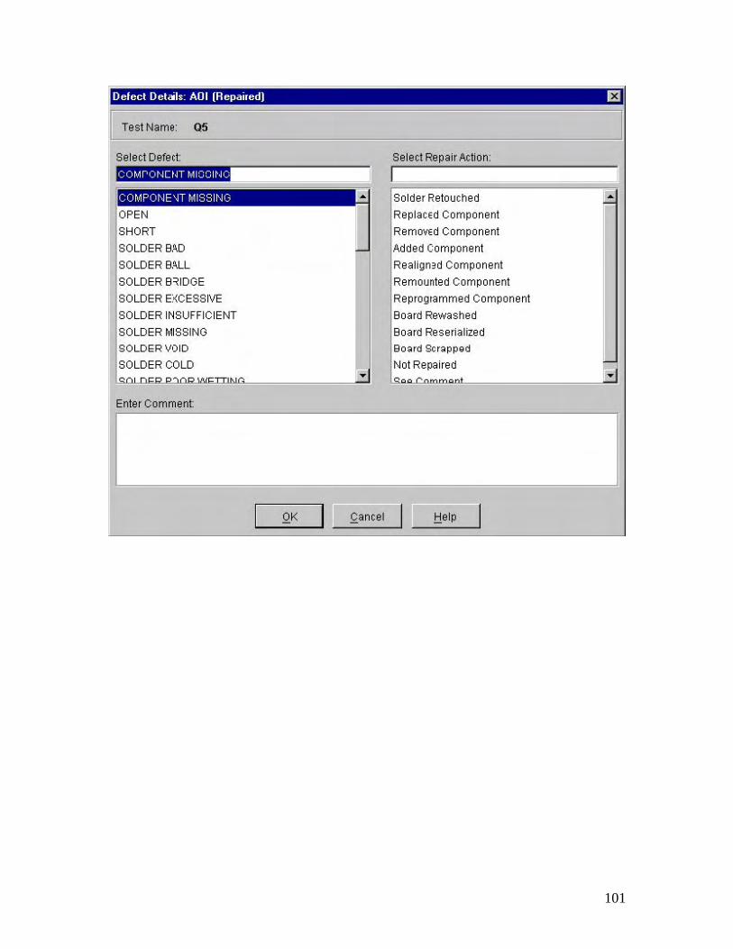
Defect Details After the Repaired, Repair Later, or Variation OK button is selected, the Defect Details dialog box may appear.
When the Defect Details dialog box appears, you have the opportunity to:
• Select the components or pins that were repaired or in need of repair.
• Select a different defect name, if necessary.
• Select a repair action. You will see a list of repair actions that apply to the defect you selected.
• Comment field: You may enter an optional comment regarding the repair.
For AOI, the comment field will contain the "expected text" of any OCR (Optical Character Recognition) defect. You may either add comments after the expected text or delete the information before you click OK.
Click OK when you are done with your selections in the Defect Details dialog box. Your changes appear in the Defect Table.
Examples of AXI, ICT, and AOI Defect Details below:
99
102
100
101
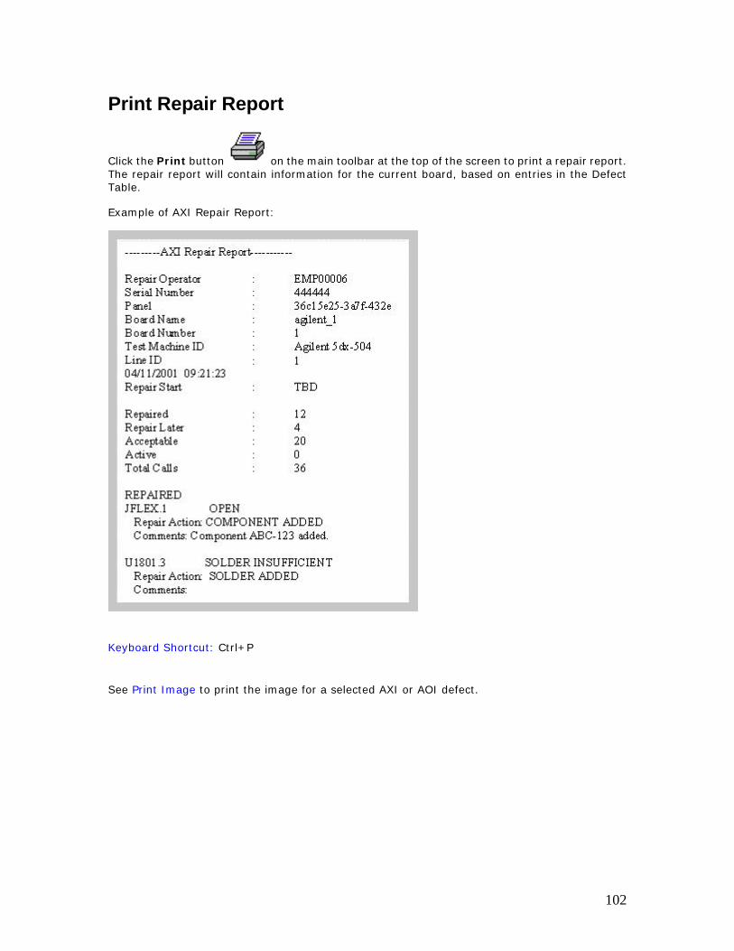
Print Repair Report
Click the Print button on the main toolbar at the top of the screen to print a repair report. The repair report will contain information for the current board, based on entries in the Defect Table.
Example of AXI Repair Report:
Keyboard Shortcut: Ctrl+P
See Print Image to print the image for a selected AXI or AOI defect.
102
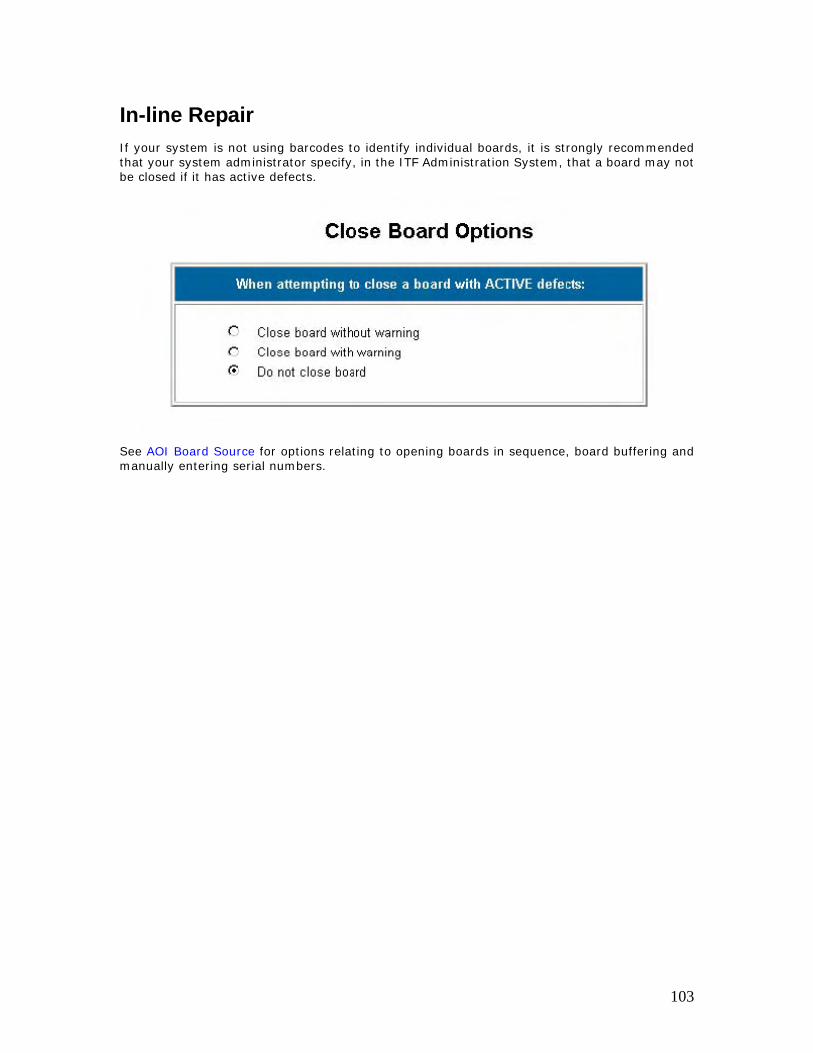
In-line Repair If your system is not using barcodes to identify individual boards, it is strongly recommended that your system administrator specify, in the ITF Administration System, that a board may not be closed if it has active defects.
See AOI Board Source for options relating to opening boards in sequence, board buffering and manually entering serial numbers.
103
Administrator Reference ART Data Source
What is a Data source?
The Agilent Repair Tool data source specifies the location where the test data is stored.
When can you change the data source?
You must change the data source before you log in to the Agilent Repair Tool. If you are currently logged in, you must log out before you can change the data source.
Why would you change the data source?
The data source would need to be changed if you need to change the IP Address or hostname, for example, when the test station is relocated or removed.
How do you change the data source?
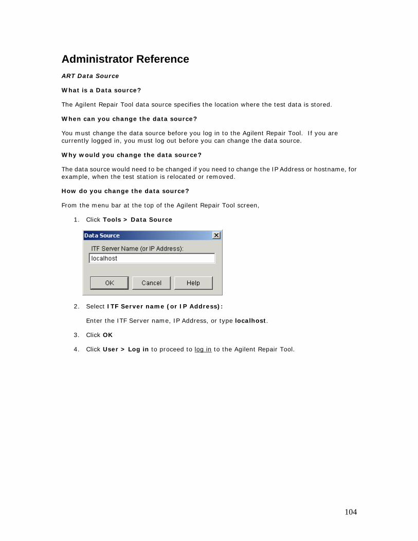
From the menu bar at the top of the Agilent Repair Tool screen,
1. Click Tools > Data Source
2. Select ITF Server name (or IP Address):
Enter the ITF Server name, IP Address, or type localhost.
3. Click OK
4. Click User > Log in to proceed to log in to the Agilent Repair Tool.
104
Scrap Board
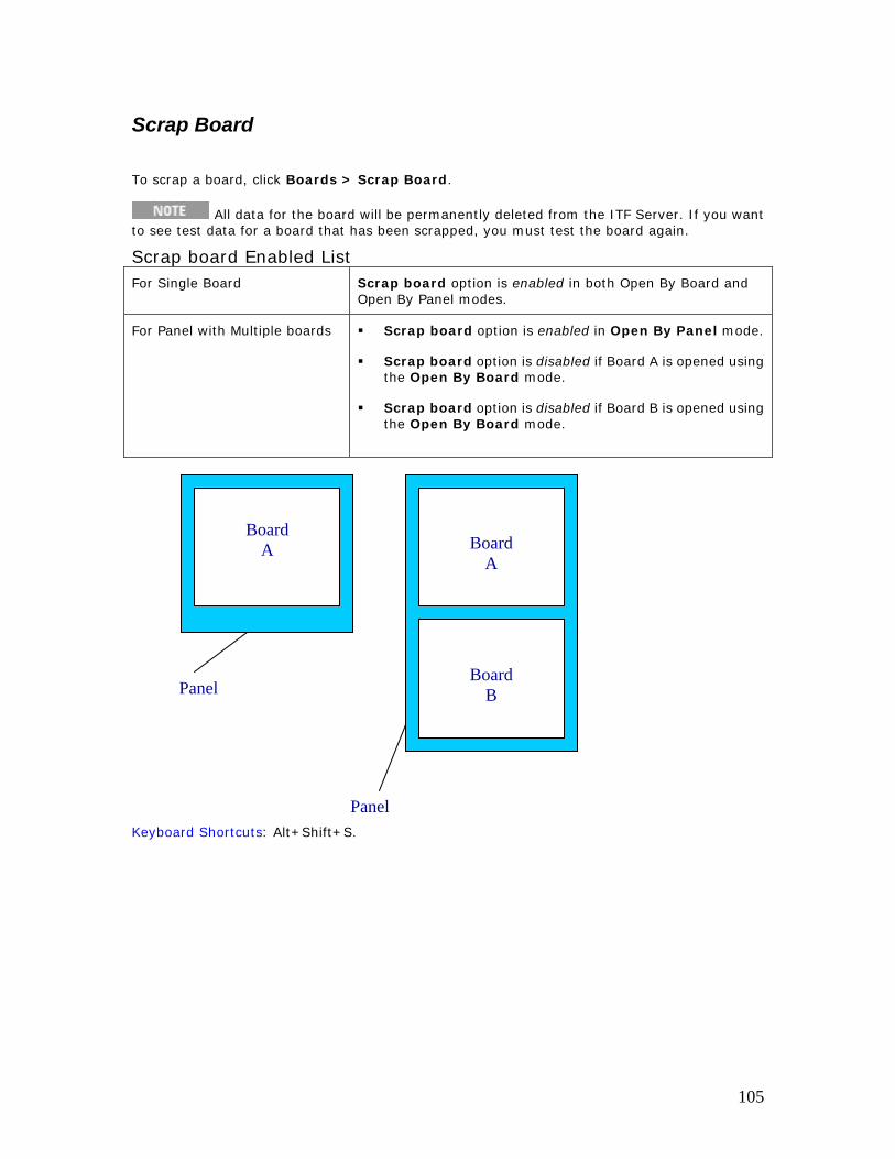
To scrap a board, click Boards > Scrap Board.
All data for the board will be permanently deleted from the ITF Server. If you want to see test data for a board that has been scrapped, you must test the board again.
Scrap board Enabled List For Single Board Scrap board option is enabled in both Open By Board and
Open By Panel modes.
For Panel with Multiple boards Scrap board option is enabled in Open By Panel mode.
Scrap board option is disabled if Board A is opened using the Open By Board mode.
Scrap board option is disabled if Board B is opened using the Open By Board mode.
Board A Board
A
Panel Board B
PanelKeyboard Shortcuts: Alt+Shift+S.
105
Board Buffering for AOI_SP/AOI_SP The Board Buffering option is useful when boards are non-serialized (no barcode labels) and you want to open boards in ART to repair them in the order they were tested. This option is available if you have selected to open boards in sequence, rather than using serial numbers.
The Board Buffering option and the Open Boards in Sequence option are available on the Tools > Administration > AOI Board Source dialog box.
A user must have Repair Administrator privileges to access the Administration dialog boxes.
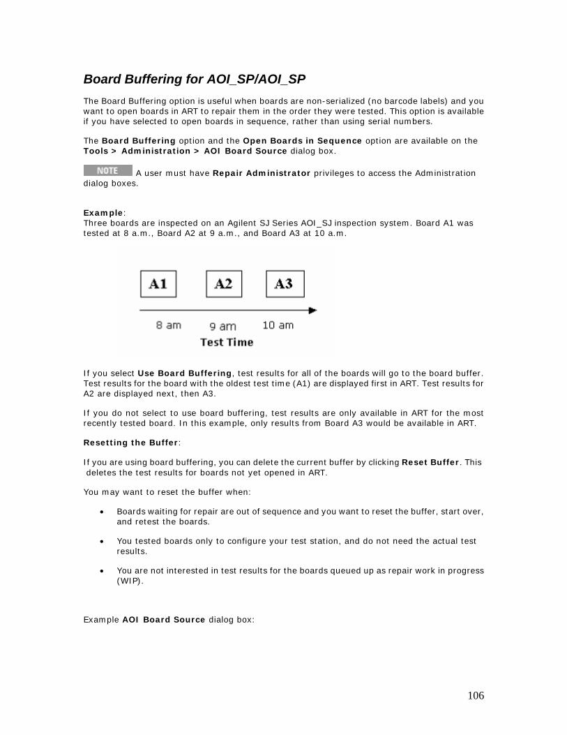
Example: Three boards are inspected on an Agilent SJ Series AOI_SJ inspection system. Board A1 was tested at 8 a.m., Board A2 at 9 a.m., and Board A3 at 10 a.m.
If you select Use Board Buffering, test results for all of the boards will go to the board buffer. Test results for the board with the oldest test time (A1) are displayed first in ART. Test results for A2 are displayed next, then A3.
If you do not select to use board buffering, test results are only available in ART for the most recently tested board. In this example, only results from Board A3 would be available in ART.
Resetting the Buffer:
If you are using board buffering, you can delete the current buffer by clicking Reset Buffer. This deletes the test results for boards not yet opened in ART.
You may want to reset the buffer when:
• Boards waiting for repair are out of sequence and you want to reset the buffer, start over, and retest the boards.
• You tested boards only to configure your test station, and do not need the actual test results.
• You are not interested in test results for the boards queued up as repair work in progress (WIP).
Example AOI Board Source dialog box:
106

107
Add Board Serial Number
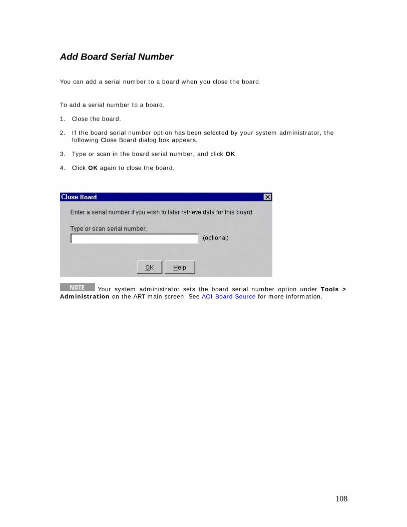
You can add a serial number to a board when you close the board.
To add a serial number to a board,
1. Close the board.
2. If the board serial number option has been selected by your system administrator, the following Close Board dialog box appears.
3. Type or scan in the board serial number, and click OK.
4. Click OK again to close the board.
Your system administrator sets the board serial number option under Tools > Administration on the ART main screen. See AOI Board Source for more information.
108
ART Settings System administrators can use the ITF Administration System to configure the following ART features:
• Status buttons
• Close board dialog box
• Repair actions
• Function keys
• Defect list
• Test station names
For more information, see the ITF Administration System online help.
109
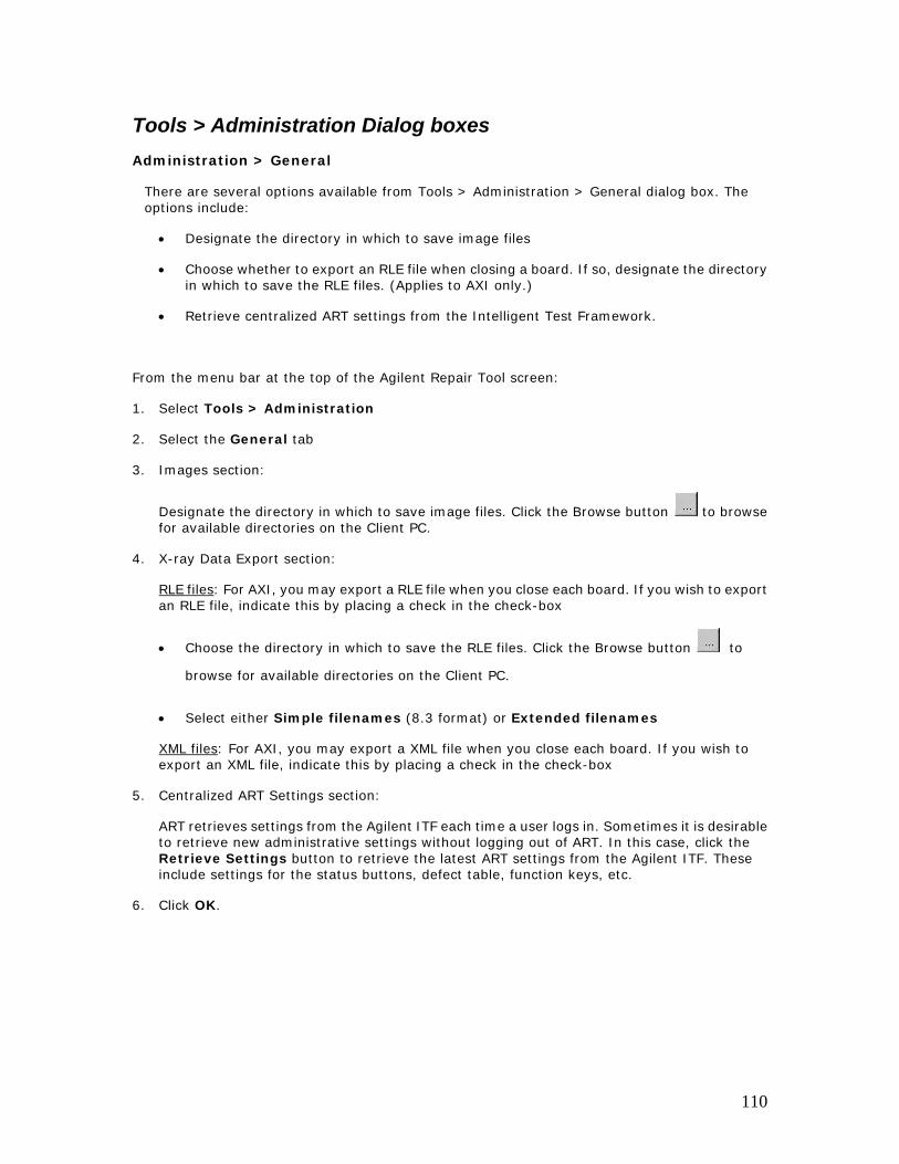
Tools > Administration Dialog boxes Administration > General
There are several options available from Tools > Administration > General dialog box. The options include:
• Designate the directory in which to save image files
• Choose whether to export an RLE file when closing a board. If so, designate the directory in which to save the RLE files. (Applies to AXI only.)
• Retrieve centralized ART settings from the Intelligent Test Framework.
From the menu bar at the top of the Agilent Repair Tool screen:
1. Select Tools > Administration
2. Select the General tab
3. Images section:
Designate the directory in which to save image files. Click the Browse button to browse for available directories on the Client PC.
4. X-ray Data Export section:
RLE files: For AXI, you may export a RLE file when you close each board. If you wish to export an RLE file, indicate this by placing a check in the check-box
• Choose the directory in which to save the RLE files. Click the Browse button to
browse for available directories on the Client PC.
• Select either Simple filenames (8.3 format) or Extended filenames
XML files: For AXI, you may export a XML file when you close each board. If you wish to export an XML file, indicate this by placing a check in the check-box
5. Centralized ART Settings section:
ART retrieves settings from the Agilent ITF each time a user logs in. Sometimes it is desirable to retrieve new administrative settings without logging out of ART. In this case, click the Retrieve Settings button to retrieve the latest ART settings from the Agilent ITF. These include settings for the status buttons, defect table, function keys, etc.
6. Click OK.
110
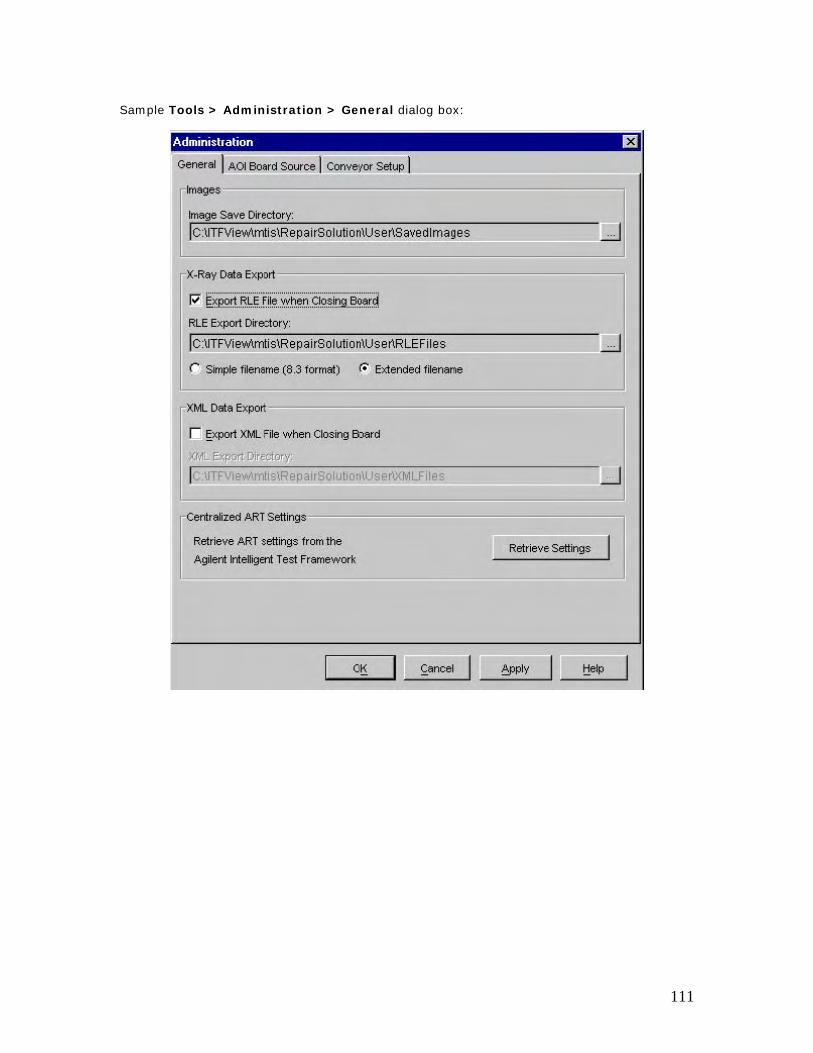
Sample Tools > Administration > General dialog box:
111
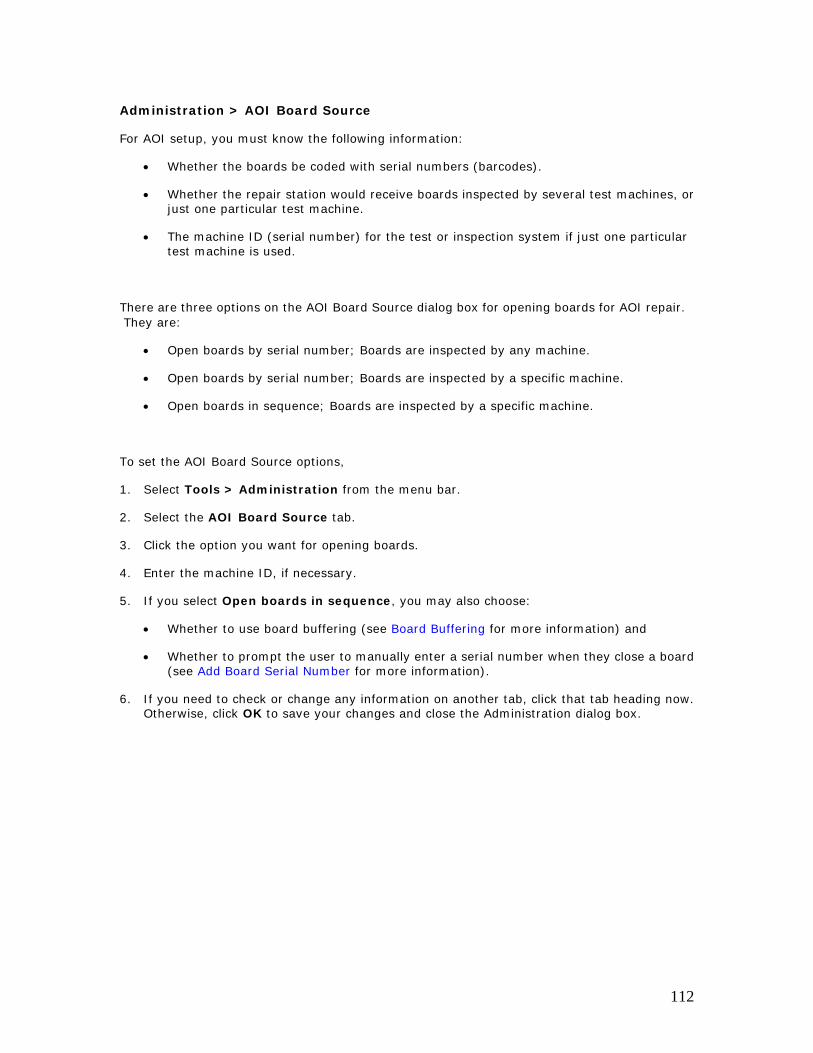
Administration > AOI Board Source
For AOI setup, you must know the following information:
• Whether the boards be coded with serial numbers (barcodes).
• Whether the repair station would receive boards inspected by several test machines, or just one particular test machine.
• The machine ID (serial number) for the test or inspection system if just one particular test machine is used.
There are three options on the AOI Board Source dialog box for opening boards for AOI repair. They are:
• Open boards by serial number; Boards are inspected by any machine.
• Open boards by serial number; Boards are inspected by a specific machine.
• Open boards in sequence; Boards are inspected by a specific machine.
To set the AOI Board Source options,
1. Select Tools > Administration from the menu bar.
2. Select the AOI Board Source tab.
3. Click the option you want for opening boards.
4. Enter the machine ID, if necessary.
5. If you select Open boards in sequence, you may also choose:
• Whether to use board buffering (see Board Buffering for more information) and
• Whether to prompt the user to manually enter a serial number when they close a board (see Add Board Serial Number for more information).
6. If you need to check or change any information on another tab, click that tab heading now. Otherwise, click OK to save your changes and close the Administration dialog box.
112
113
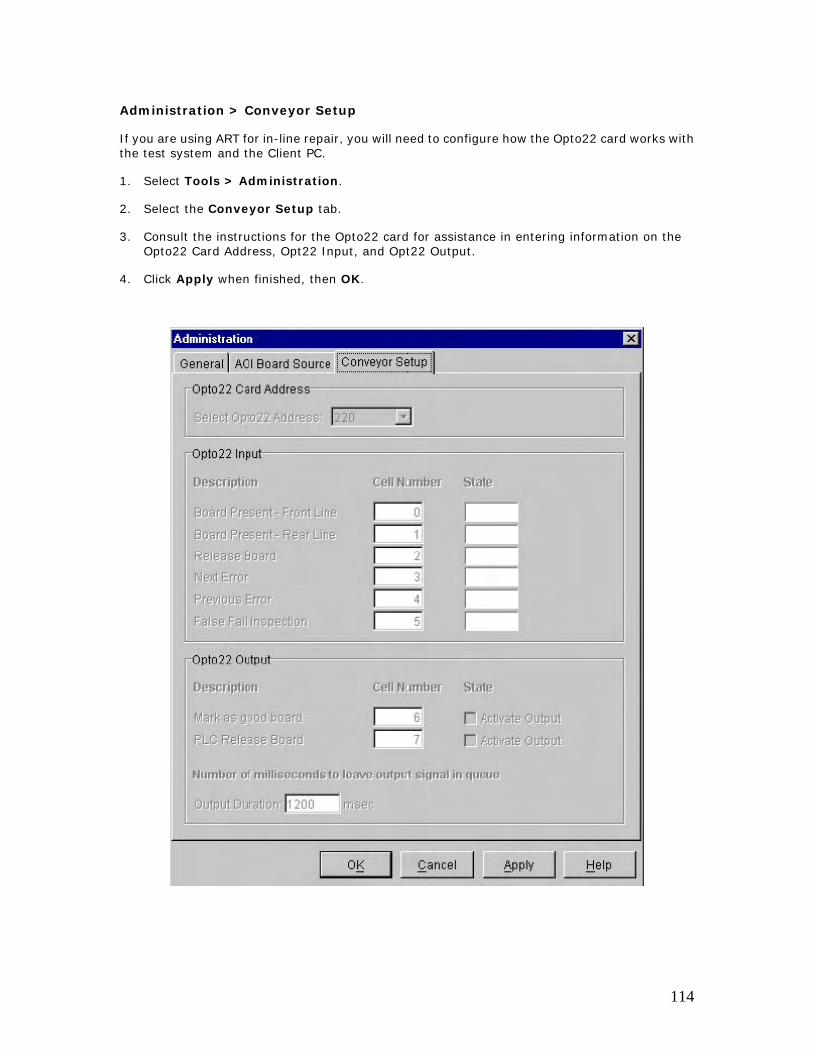
Administration > Conveyor Setup
If you are using ART for in-line repair, you will need to configure how the Opto22 card works with the test system and the Client PC.
1. Select Tools > Administration.
2. Select the Conveyor Setup tab.
3. Consult the instructions for the Opto22 card for assistance in entering information on the Opto22 Card Address, Opt22 Input, and Opt22 Output.
4. Click Apply when finished, then OK.
114
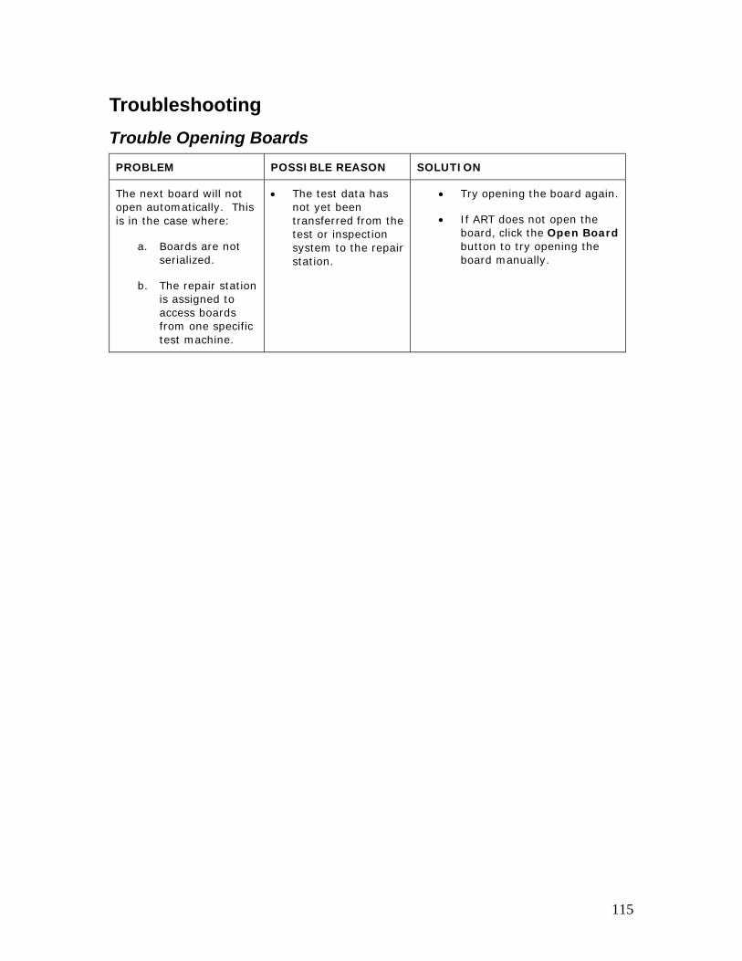
Troubleshooting Trouble Opening Boards PROBLEM POSSIBLE REASON SOLUTION
The next board will not open automatically. This is in the case where:
a. Boards are not serialized.
b. The repair station is assigned to access boards from one specific test machine.
• The test data has not yet been transferred from the test or inspection system to the repair station.
• Try opening the board again.
• If ART does not open the board, click the Open Board button to try opening the board manually.
115
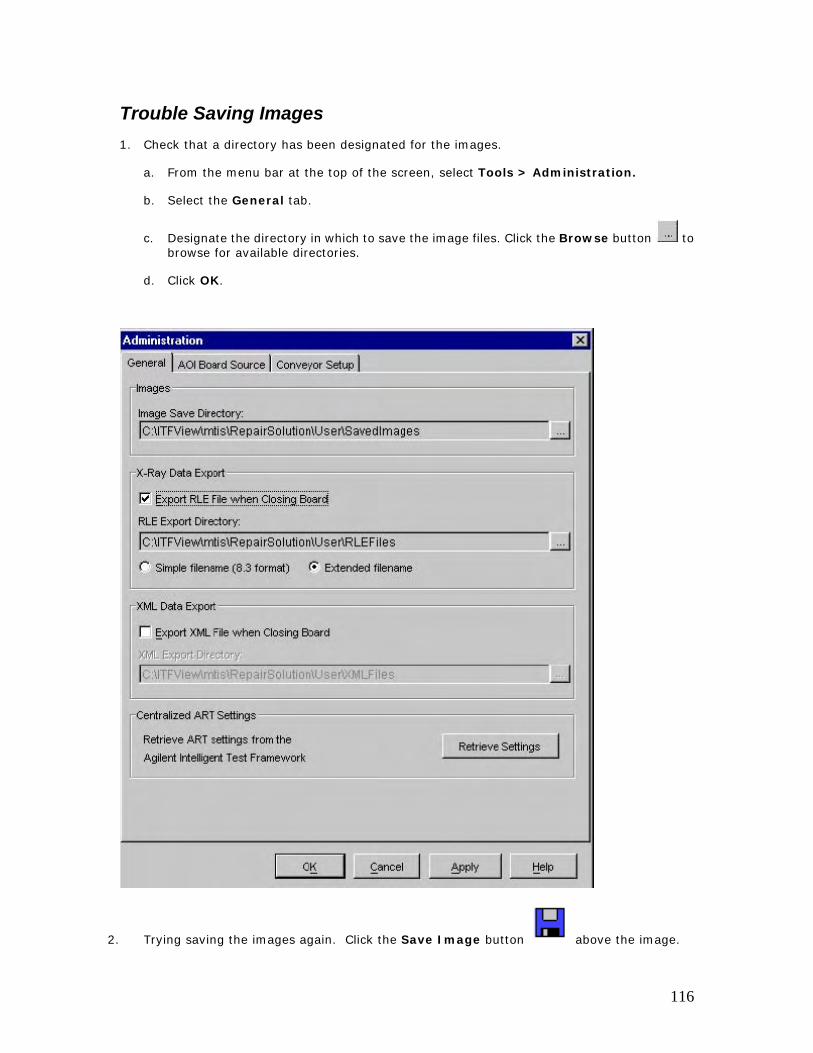
Trouble Saving Images 1. Check that a directory has been designated for the images.
a. From the menu bar at the top of the screen, select Tools > Administration.
b. Select the General tab.
c. Designate the directory in which to save the image files. Click the Browse button to browse for available directories.
d. Click OK.
2. Trying saving the images again. Click the Save Image button above the image.
116
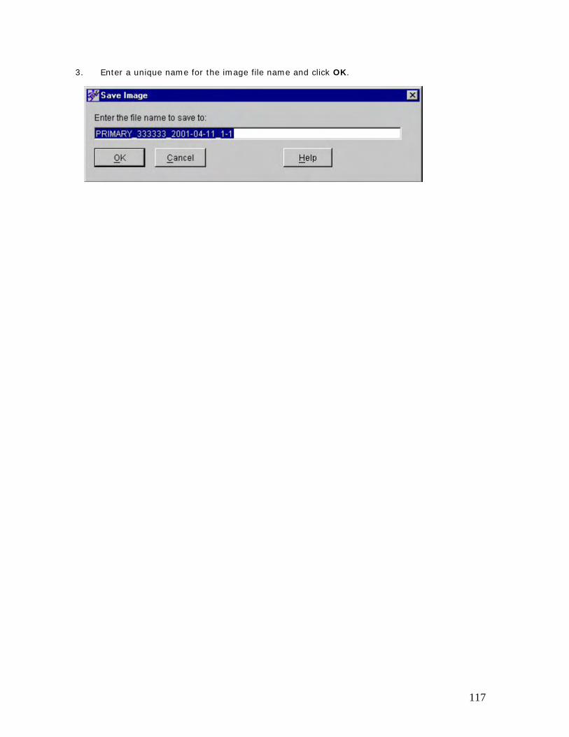
3. Enter a unique name for the image file name and click OK.
117

Trouble Viewing Buttons If you have trouble viewing the buttons located next to the Zoom View, enlarge the frame around the Zoom View area.
If you are missing the Repair Later or Variation OK button, check with your system administrator to see if the proper settings have been made in the ITF Administration System.
118

Trouble with Barcode Readers If you have problems with your barcode reader, see your barcode reader manual to verify that your barcode reader is connected properly.
A PS/2 or RS232 barcode reader may be used with the Client PC.
119
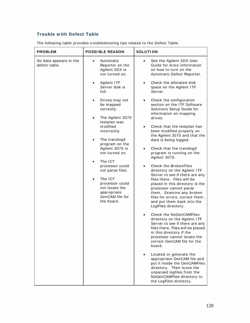
Trouble with Defect Table
The following table provides troubleshooting tips related to the Defect Table.
PROBLEM POSSIBLE REASON SOLUTION
No data appears in the defect table.
• Automatic Reporter on the Agilent 5DX is not turned on.
• Agilent ITF Server disk is full.
• Drives may not be mapped correctly.
• The Agilent 3070 testplan was modified incorrectly.
• The translogd program on the Agilent 3070 is not turned on.
• The ICT processor could not parse files.
• The ICT processor could not locate the appropriate GenCAM file for the board.
• See the Agilent 5DX User Guide for more information on how to turn on the Automatic Defect Reporter.
• Check the allocated disk space on the Agilent ITF Server.
• Check the configuration section on the ITF Software Solutions Setup Guide for information on mapping drives.
• Check that the testplan has been modified properly on the Agilent 3070 and that the data is being logged.
• Check that the translogd program is running on the Agilent 3070.
• Check the BrokenFiles directory on the Agilent ITF Server to see if there are any files there. Files will be placed in this directory is the processor cannot parse them. Examine any broken files for errors, correct them, and put them back into the LogFiles directory.
• Check the NoGenCAMFiles directory on the Agilent ITF Server to see if there are any files there. Files will be placed in this directory if the processor cannot locate the correct GenCAM file for the board.
• Located or generate the appropriate GenCAM file and put it inside the GenCAMFiles directory. Then move the unparsed logfiles from the NoGenCAMFiles directory to the LogFiles directory.
120
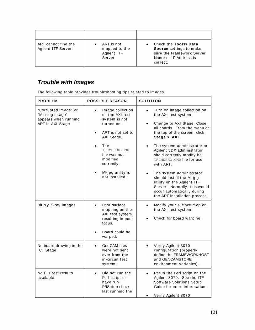
ART cannot find the Agilent ITF Server
• ART is not mapped to the Agilent ITF Server
• Check the Tools>Data Source settings to make sure the Framework Server Name or IP Address is correct.
Trouble with Images The following table provides troubleshooting tips related to images.
PROBLEM POSSIBLE REASON SOLUTION
“Corrupted image” or “Missing image” appears when running ART in AXI Stage
• Image collection on the AXI test system is not turned on.
• ART is not set to AXI Stage.
• The TRCMDPRO.CMD file was not modified correctly.
• Mkjpg utility is not installed.
• Turn on image collection on the AXI test system.
• Change to AXI Stage. Close all boards. From the menu at the top of the screen, click Stage > AXI.
• The system administrator or Agilent 5DX administrator shold correctly modify he TRCMDPRO.CMD file for use with ART.
• The system administrator should install the Mkjpg utility on the Agilent ITF Server. Normally, this would occur automatically during the ART installation process.
Blurry X-ray images • Poor surface mapping on the AXI test system, resulting in poor focus.
• Board could be warped.
• Modify your surface map on the AXI test system.
• Check for board warping.
No board drawing in the ICT Stage
• GenCAM files were not sent over from the in-circuit test system.
• Verify Agilent 3070 configuration (properly define the FRAMEWORKHOST and GENCAMSTORE environment variables).
No ICT test results available
• Did not run the Perl script or have run PRSetup since last running the
• Rerun the Perl script on the Agilent 3070. See the ITF Software Solutions Setup Guide for more information.
• Verify Agilent 3070
121
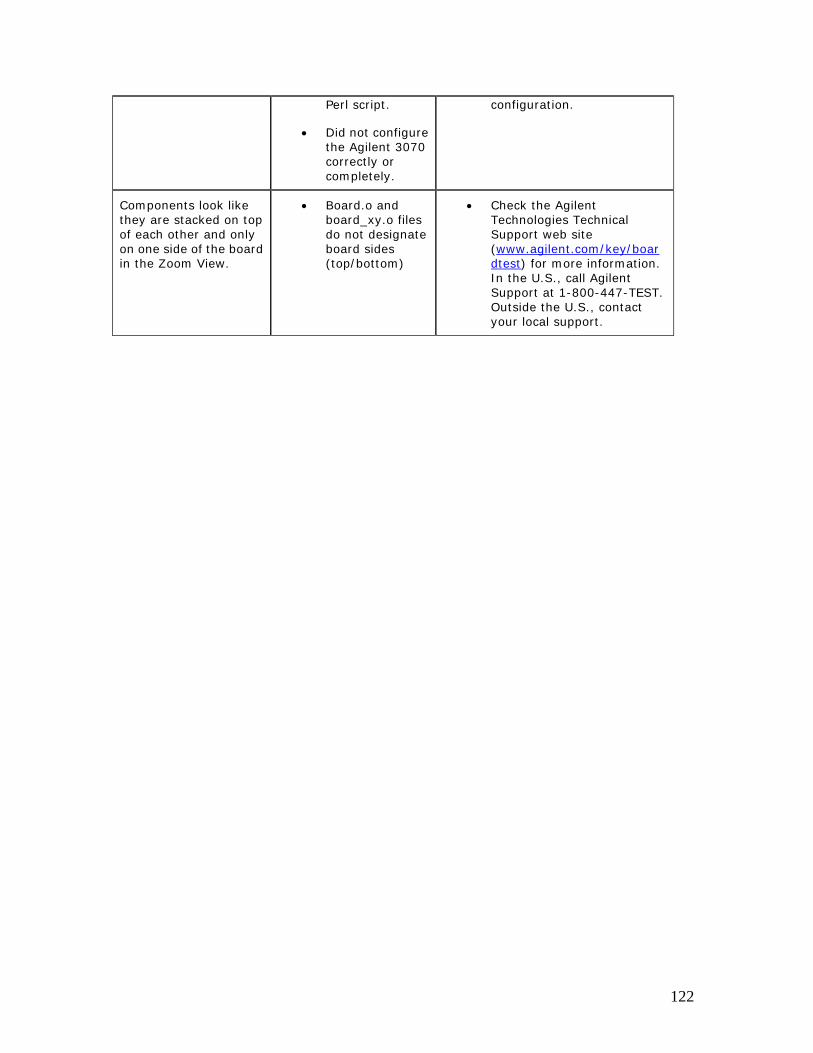
Perl script.
• Did not configure the Agilent 3070 correctly or completely.
configuration.
Components look like they are stacked on top of each other and only on one side of the board in the Zoom View.
• Board.o and board_xy.o files do not designate board sides (top/bottom)
• Check the Agilent Technologies Technical Support web site (www.agilent.com/key/boardtest) for more information. In the U.S., call Agilent Support at 1-800-447-TEST. Outside the U.S., contact your local support.
122
Trouble with Login If your User Name and/or PIN do not match the list of allowed users, you will receive an error message.
• Check whether you should enter your User Name in upper case (USER NAME) or lower case (user name).
• Make sure the Caps Lock button has not been accidentally pressed, as this could change the way the computer reads your User Name or PIN.
If you still have problems logging in, please contact your system administrator.
123
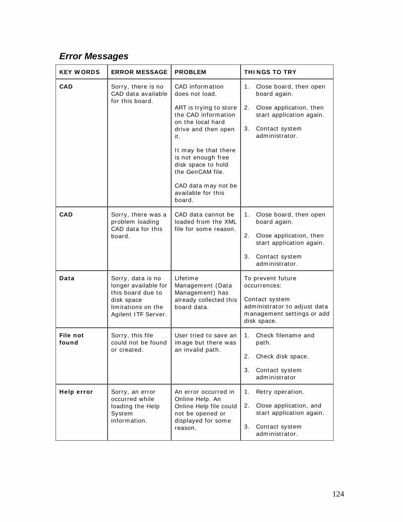
Error Messages KEY WORDS ERROR MESSAGE PROBLEM THINGS TO TRY
CAD Sorry, there is no CAD data available for this board.
CAD information does not load.
ART is trying to store the CAD information on the local hard drive and then open it.
It may be that there is not enough free disk space to hold the GenCAM file.
CAD data may not be available for this board.
1. Close board, then open board again.
2. Close application, then start application again.
3. Contact system administrator.
CAD Sorry, there was a problem loading CAD data for this board.
CAD data cannot be loaded from the XML file for some reason.
1. Close board, then open board again.
2. Close application, then start application again.
3. Contact system administrator.
Data Sorry, data is no longer available for this board due to disk space limitations on the Agilent ITF Server.
Lifetime Management (Data Management) has already collected this board data.
To prevent future occurrences:
Contact system administrator to adjust data management settings or add disk space.
File not found
Sorry, this file could not be found or created.
User tried to save an image but there was an invalid path.
1. Check filename and path.
2. Check disk space.
3. Contact system administrator
Help error Sorry, an error occurred while loading the Help System information.
An error occurred in Online Help. An Online Help file could not be opened or displayed for some reason.
1. Retry operation.
2. Close application, and start application again.
3. Contact system administrator.
124

Help system Sorry, an error occurred while loading the Help System information.
Online Help could not be opened or displayed.
1. Retry operation.
2. Close application, then start application again.
3. Contact system administrator.
Help system Sorry, the Help system has not been configured.
Online Help has not been configured.
1. If you need to see Help topics now, select Start > Programs > ITF Software Solutions > Agilent Repair Tool > Printable Help.
2. Contact system administrator.
Help topic Sorry, there was a problem accessing this Help topic.
User clicks on a Help button, but there is a problem opening the file.
1. Retry operation.
2. Click Help > Contents.
3. Contact system administrator.
In-circuit report
Sorry, the In-circuit Report is not available for this board.
The rpt file may not exist.
1. Contact the system administrator.
Internal error
Sorry, an internal error occurred when accessing data from the ITF Server
ART may be trying to access a board that is put in the Agilent ITF Server data store.
1. Retry operation.
2. Verify that the Agilent ITF Server is running.
3. Check network connection.
4. Contact system administrator.
Internet Explorer®
Sorry, Microsoft® Internet Explorer could not be found on this system. This browser is needed to display Help topics.
Microsoft® Internet Explorer could not be found on this system.
1. Contact system administrator.
ITF Operation failed
Sorry, the ITF Server operation failed.
• Network connection failure.
• Network could be down
1. Retry operation
2. Verify that the Agilent ITF Server is running.
3. Check network connection.
125
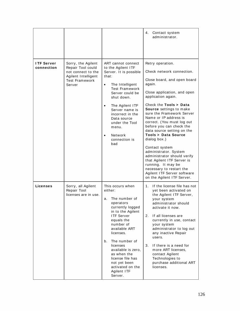
4. Contact system administrator.
ITF Server connection
Sorry, the Agilent Repair Tool could not connect to the Agilent Intelligent Test Framework Server
ART cannot connect to the Agilent ITF Server. It is possible that:
• The Intelligent Test Framework Server could be shut down.
• The Agilent ITF Server name is incorrect in the Data source under the Tool menu.
• Network connection is bad
Retry operation.
Check network connection.
Close board, and open board again.
Close application, and open application again.
Check the Tools > Data Source settings to make sure the Framework Server Name or IP address is correct. (You must log out before you can check the data source setting on the Tools > Data Source dialog box.)
Contact system administrator. System administrator should verify that Agilent ITF Server is running. It may be necessary to restart the Agilent ITF Server software on the Agilent ITF Server.
Licenses Sorry, all Agilent Repair Tool licenses are in use.
This occurs when either:
a. The number of operators currently logged in to the Agilent ITF Server equals the number of available ART licenses.
b. The number of licenses available is zero, as when the license file has not yet been activated on the Agilent ITF Server.
1. If the license file has not yet been activated on the Agilent ITF Server, your system administrator should activate it now.
2. If all licenses are currently in use, contact your system administrator to log out any inactive Repair users.
3. If there is a need for more ART licenses, contact Agilent Technologies to purchase additional ART licenses.
126
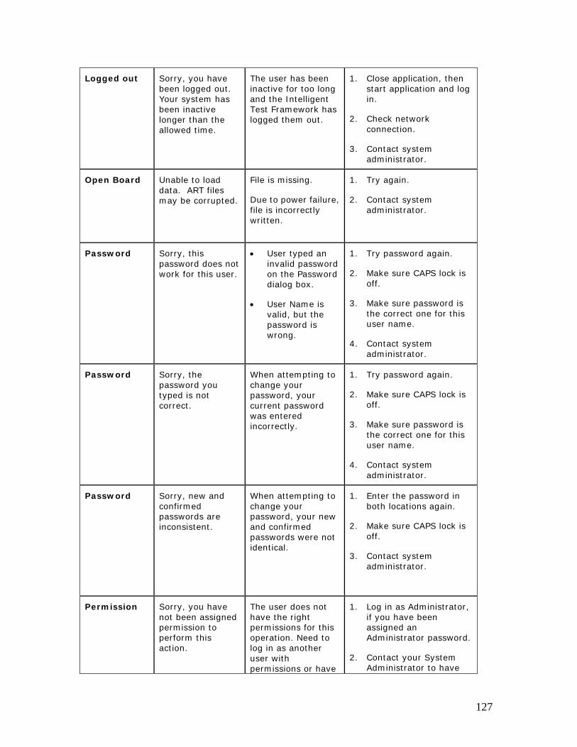
Logged out Sorry, you have been logged out. Your system has been inactive longer than the allowed time.
The user has been inactive for too long and the Intelligent Test Framework has logged them out.
1. Close application, then start application and log in.
2. Check network connection.
3. Contact system administrator.
Open Board Unable to load data. ART files may be corrupted.
File is missing.
Due to power failure, file is incorrectly written.
1. Try again.
2. Contact system administrator.
Password Sorry, this password does not work for this user.
• User typed an invalid password on the Password dialog box.
• User Name is valid, but the password is wrong.
1. Try password again.
2. Make sure CAPS lock is off.
3. Make sure password is the correct one for this user name.
4. Contact system administrator.
Password Sorry, the password you typed is not correct.
When attempting to change your password, your current password was entered incorrectly.
1. Try password again.
2. Make sure CAPS lock is off.
3. Make sure password is the correct one for this user name.
4. Contact system administrator.
Password Sorry, new and confirmed passwords are inconsistent.
When attempting to change your password, your new and confirmed passwords were not identical.
1. Enter the password in both locations again.
2. Make sure CAPS lock is off.
3. Contact system administrator.
Permission Sorry, you have not been assigned permission to perform this action.
The user does not have the right permissions for this operation. Need to log in as another user with permissions or have
1. Log in as Administrator, if you have been assigned an Administrator password.
2. Contact your System Administrator to have
127
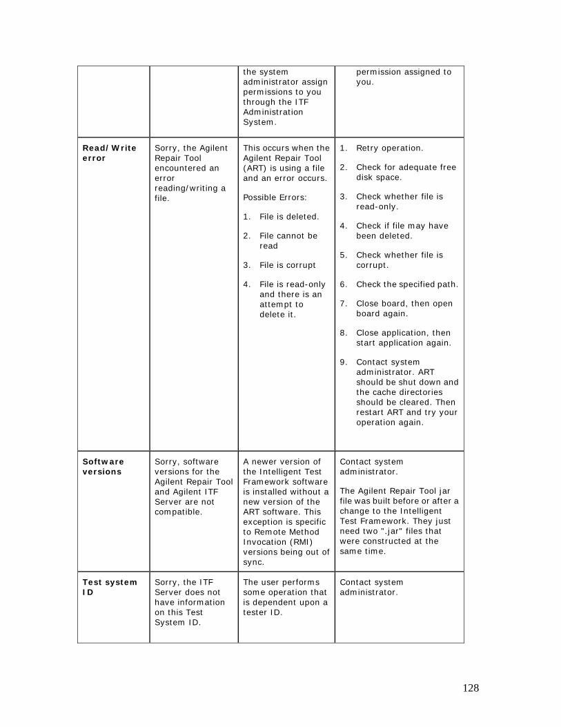
the system administrator assign permissions to you through the ITF Administration System.
permission assigned to you.
Read/Write error
Sorry, the Agilent Repair Tool encountered an error reading/writing a file.
This occurs when the Agilent Repair Tool (ART) is using a file and an error occurs.
Possible Errors:
1. File is deleted.
2. File cannot be read
3. File is corrupt
4. File is read-only and there is an attempt to delete it.
1. Retry operation.
2. Check for adequate free disk space.
3. Check whether file is read-only.
4. Check if file may have been deleted.
5. Check whether file is corrupt.
6. Check the specified path.
7. Close board, then open board again.
8. Close application, then start application again.
9. Contact system administrator. ART should be shut down and the cache directories should be cleared. Then restart ART and try your operation again.
Software versions
Sorry, software versions for the Agilent Repair Tool and Agilent ITF Server are not compatible.
A newer version of the Intelligent Test Framework software is installed without a new version of the ART software. This exception is specific to Remote Method Invocation (RMI) versions being out of sync.
Contact system administrator.
The Agilent Repair Tool jar file was built before or after a change to the Intelligent Test Framework. They just need two ".jar" files that were constructed at the same time.
Test system ID
Sorry, the ITF Server does not have information on this Test System ID.
The user performs some operation that is dependent upon a tester ID.
Contact system administrator.
128

Test Stage Sorry, current test Stage does not have data for this board.
There are no Board Test runs for a given board in this particular Stage (ICT, AXI or AOI_SJ, AOI_SP). You may be able to see the board data if you change the Stage to the type of test system on which this board was tested.
1. Please change to a different Stage.
2. If the Open Board dialog box is displayed, click Cancel.
3. From the menu bar, click Stage; then choose AXI, AOI or ICT.
4. Try opening the board again.
5. If this did not work, contact system administrator.
User Name Sorry, this user
name is not recognized by the system.
User typed an invalid name on the Login User dialog box.
Select user name from list.
If your name does not appear, contact your system administrator.
User Name Sorry, this user name is currently in use.
User is already logged in.
If you are logged in at another location, please log out now.
Contact system administrator.
129
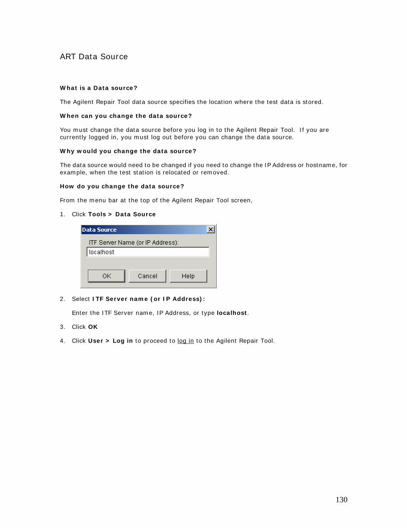
ART Data Source
What is a Data source?
The Agilent Repair Tool data source specifies the location where the test data is stored.
When can you change the data source?
You must change the data source before you log in to the Agilent Repair Tool. If you are currently logged in, you must log out before you can change the data source.
Why would you change the data source?
The data source would need to be changed if you need to change the IP Address or hostname, for example, when the test station is relocated or removed.
How do you change the data source?
From the menu bar at the top of the Agilent Repair Tool screen,
1. Click Tools > Data Source
2. Select ITF Server name (or IP Address):
Enter the ITF Server name, IP Address, or type localhost.
3. Click OK
4. Click User > Log in to proceed to log in to the Agilent Repair Tool.
130
Copyrights and Notices © Agilent Technologies, Inc. 2002-2005
No part of this manual may be reproduced in any form or by any means (including electronic storage and retrieval or translation into a foreign language) without prior agreement and written consent from Agilent Technologies, Inc. as governed by United States and international copyright laws.
Additional Notices:
The material contained in this document is subject to change without notice.
Agilent Technologies makes no warranty of any kind with regard to this material, including, but not limited to, the implied warranties of merchantability and fitness for a particular purpose. Agilent Technologies shall not be liable for errors contained herein or for incidental or consequential damages in connection with the furnishing, performance, or use of this material.
Adobe®, Acrobat® are U.S. registered trademarks of Adobe Systems Incorporated.
Notepad®, WordPad®, Windows®, and Microsoft® are U.S. registered trademarks of Microsoft Corporation.
Other trademarks and copyrights are owned by the respective companies mentioned in this document.
131
Appendixes Starting up the Software To start the Agilent Repair Tool software,
1. Start the application by doing one of the following:
• Double-click the Agilent Repair Tool icon on your computer's desktop or:
• Click Start > Programs > ITF Software Solutions > Agilent Repair Tool > Agilent Repair Tool 3.1
2. Log in. Click the Login button on the toolbar at the top of the screen.
a. Type your User Name or select it from the drop-down list.
b. Press Enter or click OK.
c. Enter your Password/PIN if it is required at your company.
d. Press Enter or click OK.
3. Before you open a board, determine whether you will be working with board test results from AXI, ICT or AOI_SJ/AOI_SP.
From the menu bar at the top of the Agilent Repair Tool screen, select:
• Stage > AOI_SJ (Optical) for boards tested by optical solder joint inspection,
• Stage > AOI_SP (Optical) for boards tested by optical solder paste inspection,
• Stage > AXI (X-ray) for boards tested by X-ray inspection, or
• Stage > ICT > In-circuit for boards tested by in-circuit test methods.
4. Click the Open Board button on the toolbar at the top of the screen if the Open Board dialog box does not appear automatically. Open a board in one of the following ways:
• Scan the board serial number with a barcode scanner.
• Scan the board serial number or panel serial number with a barcode scanner.
• Type the board serial number in the entry field.
• Browse for available board serial numbers of a particular board type by clicking the
Browse button . See Search for Board by Type for additional information.
5. You are now ready to view the defect list and images for this board.
132

How ART uses IPC Standards
The Agilent Repair Tool is based on ANSI/IPC standards 2511 (GenCAM). IPC
133
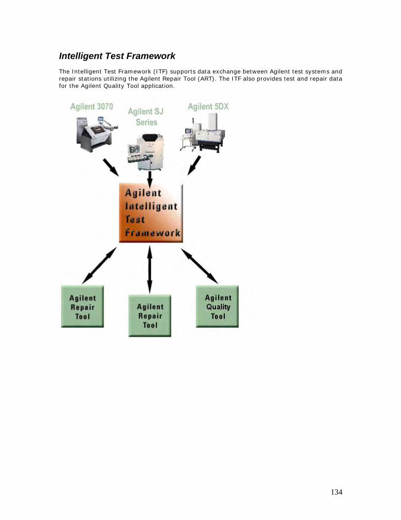
Intelligent Test Framework The Intelligent Test Framework (ITF) supports data exchange between Agilent test systems and repair stations utilizing the Agilent Repair Tool (ART). The ITF also provides test and repair data for the Agilent Quality Tool application.
134
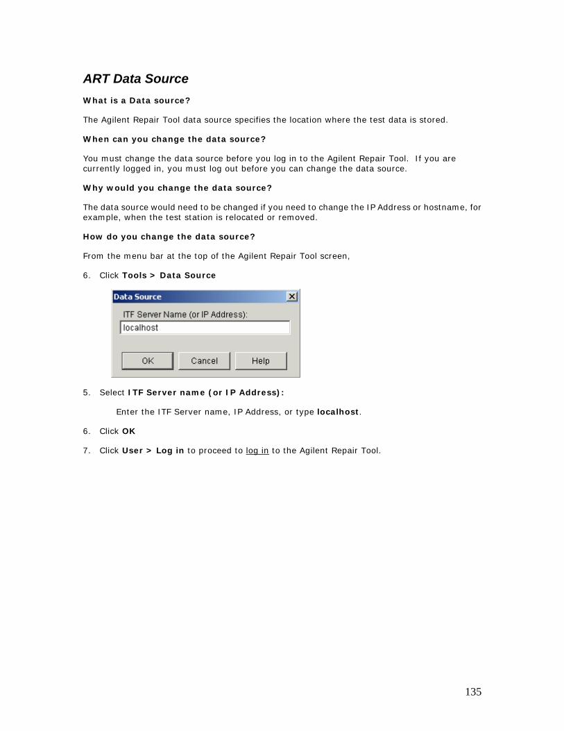
ART Data Source What is a Data source?
The Agilent Repair Tool data source specifies the location where the test data is stored.
When can you change the data source?
You must change the data source before you log in to the Agilent Repair Tool. If you are currently logged in, you must log out before you can change the data source.
Why would you change the data source?
The data source would need to be changed if you need to change the IP Address or hostname, for example, when the test station is relocated or removed.
How do you change the data source?
From the menu bar at the top of the Agilent Repair Tool screen,
6. Click Tools > Data Source
5. Select ITF Server name (or IP Address):
Enter the ITF Server name, IP Address, or type localhost.
6. Click OK
7. Click User > Log in to proceed to log in to the Agilent Repair Tool.
135
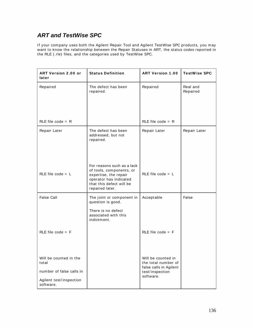
ART and TestWise SPC If your company uses both the Agilent Repair Tool and Agilent TestWise SPC products, you may want to know the relationship between the Repair Statuses in ART, the status codes reported in the RLE (.rle) files, and the categories used by TestWise SPC.
ART Version 2.00 or later
Status Definition ART Version 1.00 TestWise SPC
Repaired
RLE file code = R
The defect has been repaired.
Repaired
RLE file code = R
Real and Repaired
Repair Later
RLE file code = L
The defect has been addressed, but not repaired.
For reasons such as a lack of tools, components, or expertise, the repair operator has indicated that this defect will be repaired later.
Repair Later
RLE file code = L
Repair Later
False Call
RLE file code = F
Will be counted in the total
number of false calls in
Agilent test/inspection software.
The joint or component in question is good.
There is no defect associated with this indictment.
Acceptable
RLE file code = F
Will be counted in the total number of false calls in Agilent test/inspection software.
False
136
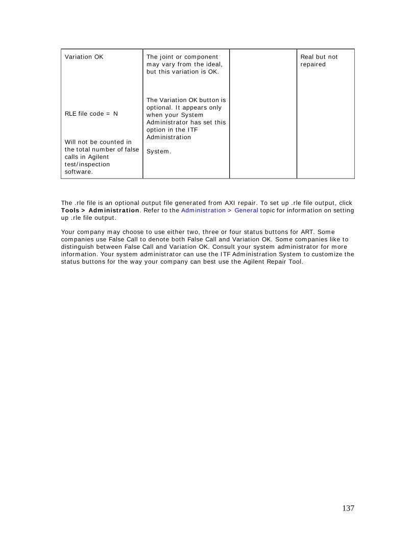
Variation OK
RLE file code = N
Will not be counted in the total number of false calls in Agilent test/inspection software.
The joint or component may vary from the ideal, but this variation is OK.
The Variation OK button is optional. It appears only when your System Administrator has set this option in the ITF Administration
System.
Real but not repaired
The .rle file is an optional output file generated from AXI repair. To set up .rle file output, click Tools > Administration. Refer to the Administration > General topic for information on setting up .rle file output.
Your company may choose to use either two, three or four status buttons for ART. Some companies use False Call to denote both False Call and Variation OK. Some companies like to distinguish between False Call and Variation OK. Consult your system administrator for more information. Your system administrator can use the ITF Administration System to customize the status buttons for the way your company can best use the Agilent Repair Tool.
137
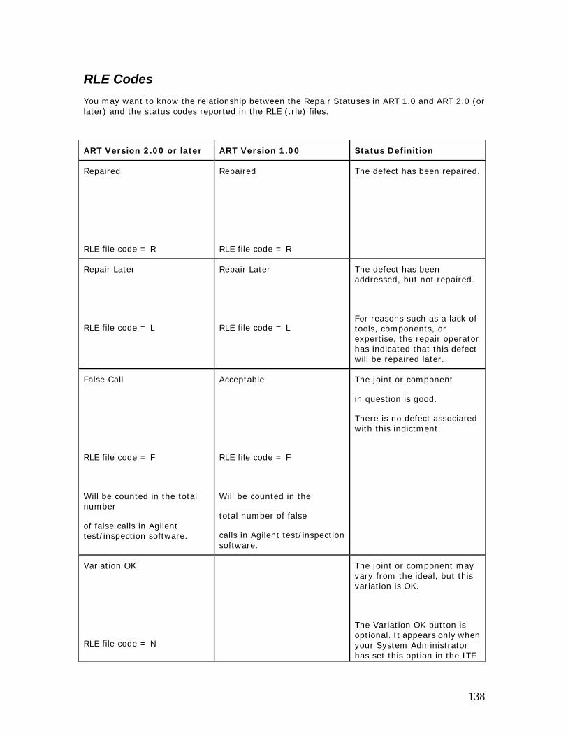
RLE Codes You may want to know the relationship between the Repair Statuses in ART 1.0 and ART 2.0 (or later) and the status codes reported in the RLE (.rle) files.
ART Version 2.00 or later ART Version 1.00 Status Definition
Repaired
RLE file code = R
Repaired
RLE file code = R
The defect has been repaired.
Repair Later
RLE file code = L
Repair Later
RLE file code = L
The defect has been addressed, but not repaired.
For reasons such as a lack of tools, components, or expertise, the repair operator has indicated that this defect will be repaired later.
False Call
RLE file code = F
Will be counted in the total number
of false calls in Agilent test/inspection software.
Acceptable
RLE file code = F
Will be counted in the
total number of false
calls in Agilent test/inspection software.
The joint or component
in question is good.
There is no defect associated with this indictment.
Variation OK
RLE file code = N
The joint or component may vary from the ideal, but this variation is OK.
The Variation OK button is optional. It appears only when your System Administrator has set this option in the ITF
138
Will not be counted in the total number of false calls in Agilent test/inspection software.
Administration System.
The .rle file is an optional output file generated from AXI repair. To set up .rle file output, click Tools > Administration. Refer to the Administration > General topic for information on setting up .rle file output.
Your company may choose to use either two, three or four status buttons for ART. Some companies use False Call to denote both False Call and Variation OK. Some companies like to distinguish between False Call and Variation OK. Consult your system administrator for more information. Your system administrator can use the ITF Administration System to customize the status buttons for the way your company can best use the Agilent Repair Tool.
139
User Roles A user with Repair User privileges can:
• Log in to the Agilent Repair Tool
• Open boards
• Repair boards
• Enter repair action and other related information
• View available X-ray images or optical images of potential defects
• View ICT report tickets
• Change password
• Access the Tools > Administration dialog boxes
A user with Repair Administrator privileges can also:
• Access the Tools > Administration dialog boxes
140

Working in Comfort To optimize your comfort and productivity, it is important that you set up your work area correctly and use your equipment properly. With that in mind, Agilent Technologies has developed some set-up and use recommendations for your work station. Please read the information in the link below to learn important information based on established ergonomic principles.
http://www.agilent.com/quality/Working_In_Comfort.pdf
141
Glossary
A
active defect: A defect with the status “Active.” It has not been changed to Repaired, Repair Later, False Call or Variation OK using the Agilent Repair Tool.
active rows: The number ot rows in the Defect Table with a current status of "Active."
Administration System: See ITF Administration System.
administrator: An individual responsible for maintaining multi-user systems, including: adding and configuring stations, setting up accounts, installing and updating software. Also referred to as system administrator.
Agilent 3070: Agilent Technologies’ in-circuit board test system family.
Agilent 5DX: Agilent Technologies’ X-ray inspection system. Automated X-ray Inspection (AXI) uses 3-D X-ray testing to locate manufacturing defects. In addition, it does not require in-circuit test probing or visual access, and does not require a fixture. AXI pinpoints the exact location of the defects, helping to make repairs both fast and inexpensive.
Agilent Quality Tool: An SPC/SQC tool for the Agilent 5DX and Agilent SJ Series test systems. The Agilent Quality Tool is a software application that runs on Client PCs. It allows users to apply SPC and SQC methods to improve assembly and test process efficiencies while helping users meet their targeted quality levels.
Agilent Repair Tool: The common repair tool for the Agilent 3070, Agilent 5DX, and Agilent SJ series test and inspection systems. The Agilent Repair Tool is a software application that runs on a Client PC. Common abbreviation is ART.
Agilent SJ Series: Agilent Technologies’ automated optical inspection systems. Current products are the Agilent SJ10 and SJ50 inspection systems.
algorithm: On the Agilent 5DX, there are "algorithm families" of BGA, BGA2, Gullwing, FPGullwing, Connector, Res, Cap or Chip. Algorithm types correspond to different physical entities on the board. The Agilent SJ Series also has algorithm types that parallel the "algorithm family" on the Agilent 5DX. Since the Agilent 5DX is concerned with the structure of the joint, a 5DX algorithm "family" is based on structure. The Agilent SJ Series is more concerned with the shape of the body of the component, so the SJ Series algorithms are based on shape.
AOI: Automated Optical Inspection. The Agilent SJ10 and SJ50 are automated optical inspection (AOI) systems.
ART: Abbreviation for Agilent Repair Tool.
assembly: See Board
assembly process: Test systems, software, and methodologies used in the development of printed circuit board technology.
assembly type: See Board Type
attribute: A variable used by an Agilent inspection machine that specifies how certain Neutral Data File (NDF) data is to be interpreted or used.
142
AXI: Automated X-ray inspection. The Agilent 5DX X-ray inspection system is an AXI system.
B bandwidth: The capacity for data transfer of an electronic communications system. In computer
networks, greater bandwidths reflects faster data communication speeds.
Bandwidth is often expressed in bits per second (bps), kilobits per second (kbps), or megabits per second (mps).
barcode reader: A device that reads a barcode containing a serial number from a board or panel. Usually hand-held, although some barcode scanners are mounted on a test system.
board: The physical printed circuit board containing the devices intended for test. One or more copies of a board may exist on a panel.
board buffering: Board buffering is often used when boards are non-serialized and operators want to open and repair boards in the order they were tested. The Board Buffering option is found on the Tools > Administration > AOI Board Source dialog box.
board drawing: The Board View or Zoom View of the board drawing in the Agilent Repair Tool AXI, AOI or ICT screen (lower half of screen). The board drawing displays the components from the CAD data.
board navigation: Term used to describe the action of locating items of interest on a board drawing.
board type: The classification of a specific printed circuit board assembly type, usually named or numbered.
Boards Tested but Not Reviewed: Boards that have failed test and have not been completely reviewed using the Agilent Repair Tool.
C CAD: Abbreviation for Computer Aided Design. For the Agilent 5DX or Agilent SJ Series
inspection systems, CAD data is the source data used to design or describe an unpopulated circuit board. For Agilent in-circuit test systems, CAD data is used to describe the layout of a printed circuit board to the test machine.
Client PC: The computer on which the Agilent Repair Tool or Agilent Quality Tool software runs.
close board: An action taken in the Agilent Repair Tool to close a board.
completely reviewed: A board has been completely reviewed at ART when all test calls have been marked either Repaired, Repair Later, False Call or Variation OK. There are no Active defects remaining on the board.
component: An individual part with contacts (pins) that are connected with solder joints to a corresponding set of pads (land pattern) on a board. Also referred to as a Device.
component level defect: A defect that applies to an entire component (for example, Component Missing).
computer-aided design: See CAD
143
D data store: The subsystem within the ITF where the test and repair information is stored.
defect: A physical problem with a component or pin. The defect is specified in the Agilent Repair Tool when the component or pin is marked Repaired or Repair Later.
defect call: An item in the Defect Table or defect list. A possible defect.
defect details: A dialog box in the Agilent Repair Tool. Allows the user to enter more specific details about repair actions and defects.
defect list: A user-defined list of defect types, such as OPEN or SHORT. The list is configured in the ITF Administration System and used in Agilent ITF applications. The defects listed in the Agilent Repair Tool are based upon the Defect List.
defect table: The list of possible defects displayed in the Agilent Repair Tool user interface (upper right corner of screen). This list is generated from data provided to ART by an X-ray inspection (AXI) system, automated optical inspection (AOI) system, or an in-circuit test (ICT) machine.
defect ticket: See Defect Table. May also refer to the actual paper defect ticket generated by an inspection machine.
defective component: A component with at least one real defect. It has been marked either Repaired or Repair Later using the Agilent Repair Tool.
defective pin: A pin with at least one real defect. It has been marked either Repaired or Repair Later using the Agilent Repair Tool.
device: A component.
F
failed component: A component with at least one test call.
failed components: The number of components with at least one test call.
failed pin: A pin with at least one test call.
failed pins: The number of failed pins with at least one test call.
failure: A possible defect, called by a test system.
failures: The number of possible defects that were called by a test system.
false call: There is no defect associated with this indictment.
False DPMO: The ratio of false calls to the total number of defect opportunities.
false failure: See False Call.
feeder: See Placement feeder
framework: See Intelligent Test Framework.
I
ICT : An acronym for in-circuit test. The Agilent 3070 is an in-circuit test system.
144
image: An X-ray or optical image of a possible defect. X-ray laminography allows for X-ray images from X-ray inspection (AXI) systems such as the Agilent 5DX. Automated optical inspection allows for optical images from AOI test systems such as the Agilent SJ10 or SJ50.
in-circuit test: An analog or digital test technique that measures the value or performance of a component on the board under test. Abbreviated as ICT.
in-circuit test report: The report from an in-circuit test. For the Agilent 3070, this is the Report Ticket.
indictment: A possible defect. A defect call.
input device: A device used to enter information into a computer. Examples include a keyboard, mouse, barcode reader, or a keypad.
Intelligent Test: An Agilent Technologies strategy for electronics manufacturers that enables optimized manufacturing processes built on best in class testers and common tools.
Intelligent Test Framework: A collective term that refers to the Agilent Intelligent Test Framework software and server.
Intelligent Test Framework Server: The server hardware on which the Agilent ITF software runs.
Intelligent Test Software Solutions:
interface: Interaction or communication is achieved at an interface. A user interface is a computer screen where you receive and/or enter information.
IPC: The Institution for the Interconnecting and Packaging of Electronic Circuits. An international standards generation body that is accredited by ANSI.
IPC Standard: A type of standard developed by the IPC Association Connecting Electronics Industries. The capability supported by some operating systems that allows one process to communicate with another process. The processes can be running on the same computer or on different computers connected through a network. The Agilent Repair Tool and Agilent Quality Tool are based on ANSI/IPC standards 2547 (CAMX) and 2511 (GenCAM).
ITF: Abbreviation for Intelligent Test Framework.
ITF Administration System : A browser-based application on the ITF Server that is used to configure system properties such as user access, repair configurations and framework services for ITF Software Applications.
ITF Server: See Intelligent Test Framework Server
ITF Software: The software that allows for data sharing and communication among test systems and applications, such as the Agilent Repair Tool and Agilent Quality Tool.
ITF Software Solutions: A suite of software applications that run on the Intelligent Test Framework.
K keypad: A keypad is an optional input device for the Agilent Repair Tool. The keypad is
comprised of buttons for the most commonly used functions in ART. A keypad is most useful with AXI and AOI repair.
145
L LAN: See Local Area Network
layers: Board layers
Local Area Network: A group of computers at a single location (usually an office or home) that are connected by phone lines or coaxial cable.
log in: The method to establish communication with a computer program. When the Agilent Quality Tool starts up, the user must first log in to the program. Login requires a valid user name and password. Your system administrator sets up the list of valid user names and passwords.
log out: The method to end communication with a computer program. A user will log out when he/she wants to end communication with the software applications. Another user may then log in to the software application.
M MHz: Megahertz
N net: The copper lines (sometimes aluminum) on printed circuit boards that allow electricity to
flow between electronic components.
Network File System: A standard utility that allows for the sharing of network resources among Windows NT®, Windows 2000, and UNIX-based operating systems. NFS is part of Windows® Services for UNIX 2.0.
Neutral Data File: The neutral data files (NDFs) are description files for panels tested by the Agilent 5DX. The NDF files describe the layouts and test criteria. The NDFs are ASCII files that use a simple text data format. Each line in the file begins with a special identifying character and ends with a carriage return and line feed.
NFS: See Network File System.
no defect: The fault called by the test system is not a defect. See also False Call.
O open: The electrical isolation of two conductor nodes. “Open” is most commonly used when the
nodes are supposed to be electrically common, but are not.
open board: An action taken to open a board.
opens testing: A test that looks for open connections which should be closed (shorted). In printed circuit board testing, it looks for open connections between a device or component pin and the printed circuit board. In system diagnostics, opens testing looks for open relay contacts that should be closed in the system.
opportunity: Any opportunity for a defect on a pin or component.
optical tester: An optical test inspection machine. The Agilent SJ10 and SJ50 are sometimes referred to as optical testers. This equipment is more formally referred to as an automated optical inspection (AOI) system.
146
P package type: For AOI, the package type is a name or code used to designate the shape and
size of the component. Examples of AOI package types: SOIC14 or C1206. For AXI, the package name is usually derived from the land pattern name. The package data includes such characteristics as pin dimensions, locations, pitch and pin type. Examples of AXI package types: SO14_U or 1206_C.
page-sensitive help: A type of online help that gives specific information about the current screen.
panel: A printed circuit board assembly which can contain one or more boards. Note: for the Agilent 5DX, any single board loaded directly into the tester is considered a panel for the purpose of panel programming.
panel dimensions: The width (DX), length (DY), and thickness (DZ) of the panel.
paperless repair: A board test and repair strategy in which test and inspection data is stored electronically instead of printed immediately on a paper repair "ticket" (from the strip printer). Data is retrieved based on the product serial number typically read from a barcode label. The Agilent Repair Tool is an improvement on past paperless repair systems.
password: An individual identification code required to access a board, file, computer or program. The password helps ensure that unauthorized users do not access the computer.
PIN: Personal Identification Number (a numeric password).
pin level defect: A defect that applies to an individual pin or joint, rather than an entire component. Examples include Open or Short.
pin number: A unique number is assigned to every pin of a given package in the package Neutral Data File (NDF). The pin number must match the respective pad number.
R RAM : Acronym for Random Access Memory. RAM can be read from or written to by the
computer or other devices.
reference designator: A name used to designate a particular component on a specific board type. Examples: U11 or R4.
Repair Later: An action taken to indicate that a specific pin or component is to be repaired later. It may be for reasons such as a lack of tools, components, or expertise that the repair operator indicates that this defect will be repaired later.
repair report: A printable summary of repair actions and defects based on entries in the Defect Table.
Repaired: An action taken to confirm or change the specific defect for this pin or component. This defect has been addressed.
reviewed board: A board with all test calls marked Repaired, Repair Later, False Call or variation OK. There are no Active defects remaining on the board.
147
RLE: run-length encoding, A kind of compression algorithm which replaces sequences ("runs") of consecutive repeated characters (or other units of data) with a single character and the length of the run. This can either be applied to all input characters, including runs of length one, or a special character can be used to introduce a run-length encoded group. The longer and more frequent the runs are, the greater the compression that will be achieved. This technique is particularly useful for encoding black and white images where the data units would be single bit pixels.
rotate board: Button in the Agilent Repair Tool that rotates the CAD display in the Zoom View 90° clockwise each time it is pressed. For AXI and AOI, the X-ray or optical image also rotates.
S S/N: See Serial number
scrapped board: A board that is discarded. A board may be marked as scrapped using the Agilent Repair Tool. Data for a scrapped board is removed from the ITF Server.
scrapped boards: The number of boards that have been discarded. A board is marked as scrapped using the Agilent Repair Tool.
serial number: A unique series of numbers and/or letters used to identify an individual board or panel. Usually encoded on a barcode label.
short: A connection of comparatively low resistance accidentally or intentionally made between points on a circuit.
show connected trace: Show a trace through all layers of the board, even if the layer is not currently visible.
solder joint: The solder connection of a component pin to its respective pad of a land pattern located on a printed circuit assembly.
stage: The stage of the manufacturing process: AOI_SJ, AOI_SP, AXI or ICT. Also referred to as Test Stage.
status: The status of a component or pin in the Agilent Repair Tool. Status is Active, Repaired, Repair Later, False Call, or Variation OK.
status bar information: The status bar at the bottom of the Agilent Repair Tool screen that displays information to the repair operator about the current board status.
T table rows: The total number of rows in the Defect Table.
test call: A named test failure, such as OPEN or MISSING.
test failure: The problem or fault identified by the test or inspection equipment. Examples: Short, Open, or Measurement Failed. The in-circuit test machine determines the test failure name.
test name: The process step ID of the in-circuit test that failed. Process Step Status record from the IPC-2547 standard. Examples: U3, R1, or C56.
test stage: The stage of the manufacturing process: AOI, AXI or ICT. Also referred to as Stage.
148
test station: A specific test or inspection system, identified by a name or identification number.
test system: A generic term used to describe a test or inspection machine, such as the Agilent 3070, Agilent 5DX, or Agilent SJ Series.
time frame: A period of time with a specific date and time for its beginning and end.
traces: The physical conductor on or within the layering of a printed circuit board.
U user name: Name used to log in to the Agilent Repair Tool from the Login dialog box. The
system administrator sets up all user names.
V Variation OK: For a given indictment in the Agilent Repair Tool, the slight variation from the
ideal is acceptable.
via: A plated through-hole that provides electrical continuity only; it is not used as a component mount. (Short for Viaduct.)
View: A View defines a subset of test, inspection, and repair data that resides on the ITF Server, forming the basis for charts in the Agilent Quality Tool. Views are created and named in the Agilent Quality Tool.
X X-ray: A form of electromagnetic radiation, similar to light, but, of shorter wavelength and
capable of penetrating solid materials. Used by X-ray inspection machines to examine printed circuit board joints.
X-ray inspection: A method of examining printed circuit board components and joints using an X-ray inspection machine such as the Agilent 5DX.
X-ray tester: An X-ray inspection machine. The Agilent 5DX inspection machine is sometimes called an X-ray tester.
XML: Abbreviation for Extensible Markup Language. XML is a specification developed by the World Wide Web Consortium. It allows designers to create their own customized tags, enabling the definition, transmission, validation, and interpretation of data between applications and between organizations.
Z zoom full board: Set the Zoom View to show the entire board drawing.
zoom in: Get a closer look at the board drawing in the Zoom View (components will appear larger).
zoom out: Show more of the board drawing in the Zoom View area (components will appear smaller).
zoom view: The Zoom View is a zoomed-in view of the board drawing. It allows for a closer look at a selected component or location on the board. The Zoom View is located in the lower right hand corner of the ART screen.
149
Index A
acceptable.......................................................................62, 63, 76, 77, 90, 91, 97, 152 Agilent Technologies on the Web ............................................................................... 10 ANSI/IPC standard .................................................................................................... 6 AOI Board Source................................................................ 25, 106, 109, 110, 111, 115 AOI Image ............................................................................................................. 64 AOI Repair Procedure............................................................................................... 57 ART Data Source ............................................................................................ 107, 139 AXI Image.........................................................................................................65, 78 AXI Repair Procedure ............................................................................................... 69
B
barcode reader ................................................................................................ 27, 122 Benefits of the Agilent Repair Tool ............................................................................... 8 board buffering ....................................................................................... 106, 109, 115 Board Buffering.............................................................................................. 109, 115 board display options ..........................................................................................50, 92 Board Display Options.............................................................................. 50, 61, 74, 88 board layers ......................................................................................................92, 93 board serial number........................................................................ 21, 22, 25, 111, 135 Board serial number ................................................................................................ 56 Board Serial Number.............................................................................................. 115 board view ............................................................................................................. 87 Board View..................................................................47, 50, 60, 62, 72, 73, 76, 87, 90
C
Change Password ............................................................................................. 26, 144 clear highlights ....................................................................................................... 93 Clear Highlights............................................................................ 31, 33, 45, 61, 75, 89 Close Board................................................................... 16, 25, 111, 112, 127, 129, 131 Comment field ...................................................................................................... 101 Conveyor Setup .................................................................................................... 117 Copyrights and Notices........................................................................................... 134 cross-hair............................................................................................... 50, 61, 74, 88
D
data source .......................................................................................................... 107 Data source.......................................................................................................... 129 Data Source .................................................................................................. 124, 133 data store ............................................................................................................ 128 defect details ........................................................................ 62, 76, 77, 90, 95, 99, 101 defect status......................................................................................................85, 98
E
Error Messages ..................................................................................................... 127 expected text........................................................................................................ 101
F
False Call ......................................... 31, 33, 59, 63, 71, 77, 85, 91, 96, 98, 140, 141, 142 features ...................................................................................................... 6, 16, 112 Find Component...................................................................................................... 38 Find Connected Items ................................................................................... 30, 55, 88 Find Net................................................................................................................. 40 Find Short .............................................................................................................. 43 function keys ................................................................................. 16, 33, 34, 112, 113
150
H
Highlights.................................................................................................... 31, 33, 45 How ART uses IPC Standards .................................................................................. 137
I
ICT Repair Procedure ............................................................................................... 84 image................................. 6, 48, 58, 64, 66, 67, 70, 79, 81, 82, 105, 113, 119, 120, 124 Image ............................................................................. 29, 32, 57, 62, 64, 65, 76, 78 image indicator ..................................................................................................58, 79 image slice ............................................................................................................. 79 In-circuit report .................................................................................................... 128 In-circuit Report...................................................................................................6, 90 In-Circuit Report ..................................................................................................... 84 Intelligent Test Framework ................................................9, 15, 113, 129, 130, 131, 138 IPC...................................................................................................................8, 137 ITF Administration System....... 15, 16, 22, 25, 33, 95, 97, 98, 106, 112, 121, 131, 141, 143 ITF Server........................................................ 9, 37, 108, 123, 124, 127, 128, 129, 131
K
Key Features ............................................................................................................ 6 Keyboard and Mouse................................................................................................ 28 Keyboard Shortcuts .....................................................................................29, 55, 108 keypad .............................................................................................. 6, 26, 34, 35, 37
L
layers ......................................................................................................... 46, 88, 93 login...................................................................................................................... 56 Login ................................................................................................... 13, 17, 18, 135 Logout ................................................................................................................... 19
M
Minimum System Requirements................................................................................... 9
N
next image............................................................................................. 32, 70, 79, 80 no defect ........................................................................................... 96, 98, 140, 142
O
open board........................................................................................................... 127 Open Board ............................................................................21, 22, 27, 130, 132, 135
P
Page-Sensitive ........................................................................................................ 11 password ............................................................................................................... 26 Password ............................................................................................. 10, 13, 17, 130 Print image............................................................................................................. 58 Print Image ................................................................................................. 32, 66, 81 Print Repair Report ......................................................................................31, 33, 105
R
repair actions............................................................................................... 6, 98, 101 Repair actions.................................................................................................. 16, 112 Repair Actions......................................................................................................... 94 Repair Later ..................................................31, 33, 58, 62, 71, 76, 85, 95, 98, 140, 142 repaired................................................................................................................. 95 Repaired ................................................................31, 33, 58, 62, 71, 98, 101, 140, 142 RLE Codes............................................................................................................ 142
151
rle file output................................................................................................. 141, 143 Rotate Board .......................................................................................... 32, 47, 61, 88
S
Save image ............................................................................................................ 58 Save Image................................................................................................. 32, 67, 82 Scrap Board .................................................................................................... 29, 108 serial numbers ........................................................................................ 106, 109, 115 Show Connected Trace.................................................................................. 46, 88, 93 Stage ................................................................................................ 20, 29, 124, 135 Starting up the Software ........................................................................................ 135 Status Bar Information............................................................................................. 56 system administrator ................................................ 58, 59, 71, 85, 95, 97, 98, 106, 121 System Administrator .............................................................................................. 99
T
Technical Support.................................................................................. 10, 13, 37, 125 Trouble ......................................................................118, 119, 121, 122, 123, 124, 126
U
Undo Repair Action ................................................................................................ 100
V
Variation OK ........................................................................................................... 97 View Board Layers................................................................................................... 92 View Both Sides of Board.......................................................................................... 54 View Bottom Side of Board ....................................................................................... 53
X
X-ray................................................................................................................69, 78 X-ray Data Export ................................................................................................. 113
Z
Zoom Full Board...................................................................................................... 49 Zoom In................................................................................................................. 48 Zoom Out .............................................................................................................. 48 Zoom View ........................................................................................................50, 60
152