ari-stevi 470 / 471 (dn15-150) · pdf fileauma sar 07.2 - 14.6 ... ari-stevi ® 470 / 471...
TRANSCRIPT
Edition 05/17 - Data subject to alteration - Regularly updated data on www.ari-armaturen.com! Data sheet 470001 englisch (english)
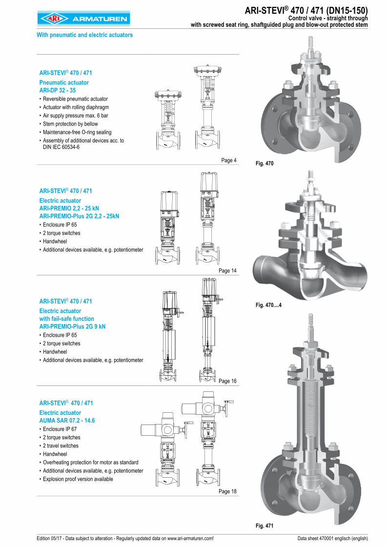
ARI-STEVI® 470 / 471 Pneumatic actuator ARI-DP 32 - 35• Reversible pneumatic actuator• Actuator with rolling diaphragm• Air supply pressure max. 6 bar• Stem protection by bellow• Maintenance-free O-ring sealing• Assembly of additional devices acc. to
DIN IEC 60534-6
Page 4
ARI-STEVI® 470 / 471 Electric actuator ARI-PREMIO 2,2 - 25 kNARI-PREMIO-Plus 2G 2,2 - 25kN• Enclosure IP 65• 2 torque switches• Handwheel• Additional devices available, e.g. potentiometer
Page 14
ARI-STEVI® 470 / 471 Electric actuator with fail-safe functionARI-PREMIO-Plus 2G 9 kN• Enclosure IP 65• 2 torque switches• Handwheel• Additional devices available, e.g. potentiometer
Page 16
ARI-STEVI® 470 / 471 Electric actuator AUMA SAR 07.2 - 14.6• Enclosure IP 67• 2 torque switches• 2 travel switches • Handwheel • Overheating protection for motor as standard • Additional devices available, e.g. potentiometer• Explosion proof version available
Page 18
ARI-STEVI® 470 / 471 (DN15-150)Control valve - straight through
with screwed seat ring, shaftguided plug and blow-out protected stemWith pneumatic and electric actuators
Fig. 470
Fig. 471
Fig. 470....4

2 Edition 05/17 - Data subject to alteration - Regularly updated data on www.ari-armaturen.com!
ARI-STEVI® 470 / 471 (DN15-150)Technical data
Figure Version Nominal pressure Material Nominal diameterInformation / restriction of technical rules need to be observed!ARI-Valves of EN-JL1040 are not allowed to be operated in systems acc. to TRD 110.A production permission acc. to TRB 801 No. 45 is available. (Acc. to TRB 801 No. 45 EN-JL1040 is not allowed.)The engineer, designing a system or a plant, is responsible for the selection of the correct valve. Resistance and fitness must be verified, contact manufacturer for information (refer to Product overview and Resistance list).
22.470 / 22.471 with flanges PN16 EN-JS1049 DN15-15023.470 / 23.471 with flanges PN25 EN-JS1049 DN15-15034.470 / 34.471 with flanges PN25 1.0619+N DN15-15035.470 / 35.471 with flanges PN40 1.0619+N DN15-15035.470....4 / 35.471....4 with butt weld ends PN40 1.0619+N DN25-15054.470 / 54.471 with flanges PN25 1.4581 DN15-15055.470 / 55.471 with flanges PN40 1.4581 DN15-150Other materials and versions on request.
Stem sealingFig. 470 standard optional
DN15- 150 DN15- 150 DN15- 150
I. PTFE-V-ring unit-10°C to 220°C
I. EPDM-sealing-10°C to 150°C
(allowed for water and steam up to 180°C)
II. PTFE-packing -10°C to 250°C
II. Pure graphite-packing -10°C to 450°C
Fig. 471 standard optionalDN15- 150 DN15- 100 DN125-150
III. Stainless steel-bellow with pure graphite-packing
-60°C to 450°C
III. Stainless steel-bellow with V-ring unit
-60°C to 220°C
III. Stainless steel bellows seal with EPDM-sealing-60°C to 150°C
(allowed for water and steam up to 180°C)
Pressure-temperature-ratings Intermediate values for max. permissible operational pressures can be determined by linear interpolation of the given temperature / pressure chart.
acc. to DIN EN 1092-2 -60°C to <-10°C 1) -10°C to 120°C 150°C 200°C 250°C 300°C 350°C 400°C 450°CEN-JS1049 PN16 (bar) on request 16 15,5 14,7 13,9 12,8 11,2 -- --EN-JS1049 PN25 (bar) on request 25 24,3 23 21,8 20 17,5 -- --
acc. to manufacturers standard -60°C to <-10°C 1) -10°C to 120°C 150°C 200°C 250°C 300°C 350°C 400°C 450°C1.0619+N PN25 (bar) 18,7 25 23,9 22 20 17,2 16 14,8 8,21.0619+N PN40 (bar) 30 40 38,1 35 32 28 25,7 23,8 13,1
acc. to DIN EN 1092-1 -60°C to <-10°C 1) -10°C to 100°C 150°C 200°C 250°C 300°C 350°C 400°C 450°C1.4581 25 (bar) 12,5 25 24,5 23,3 22,1 20,8 20,1 19,5 --1.4581 40 (bar) 20 40 39,2 37,3 35,4 33,3 32,1 31,2 --
1) Valve with extended bonnet, studs and nuts made of A4-70 (at temperatures below -10°C)
3Edition 05/17 - Data subject to alteration - Regularly updated data on www.ari-armaturen.com!
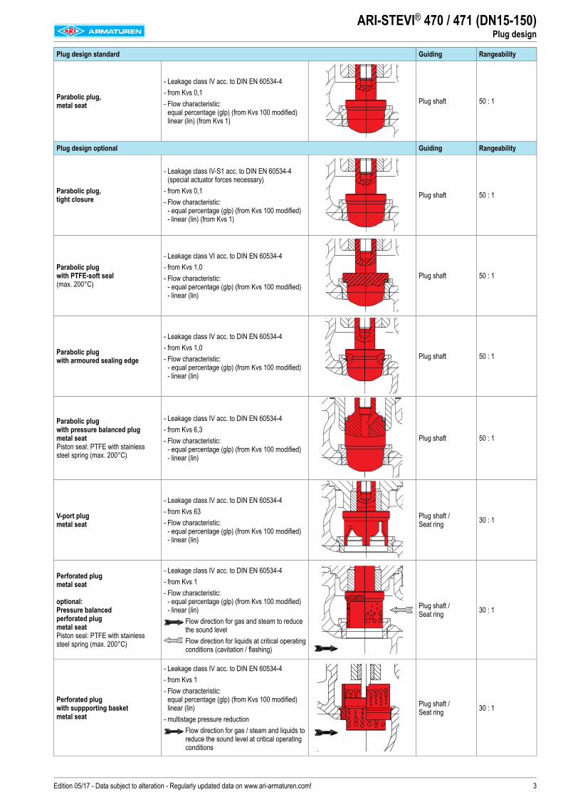
ARI-STEVI® 470 / 471 (DN15-150)Plug design
Plug design standard Guiding Rangeability
Parabolic plug, metal seat
- Leakage class IV acc. to DIN EN 60534-4- from Kvs 0,1 - Flow characteristic:
equal percentage (glp) (from Kvs 100 modified) linear (lin) (from Kvs 1)
Plug shaft 50 : 1
Plug design optional Guiding Rangeability
Parabolic plug, tight closure
- Leakage class IV-S1 acc. to DIN EN 60534-4 (special actuator forces necessary)
- from Kvs 0,1 - Flow characteristic:
- equal percentage (glp) (from Kvs 100 modified) - linear (lin) (from Kvs 1)
Plug shaft 50 : 1
Parabolic plug with PTFE-soft seal (max. 200°C)
- Leakage class VI acc. to DIN EN 60534-4 - from Kvs 1,0 - Flow characteristic:
- equal percentage (glp) (from Kvs 100 modified) - linear (lin)
Plug shaft 50 : 1
Parabolic plug with armoured sealing edge
- Leakage class IV acc. to DIN EN 60534-4 - from Kvs 1,0 - Flow characteristic:
- equal percentage (glp) (from Kvs 100 modified) - linear (lin)
Plug shaft 50 : 1
Parabolic plug with pressure balanced plug metal seat Piston seal: PTFE with stainless steel spring (max. 200°C)
- Leakage class IV acc. to DIN EN 60534-4 - from Kvs 6,3 - Flow characteristic:
- equal percentage (glp) (from Kvs 100 modified) - linear (lin)
Plug shaft 50 : 1
V-port plug metal seat
- Leakage class IV acc. to DIN EN 60534-4 - from Kvs 63 - Flow characteristic:
- equal percentage (glp) (from Kvs 100 modified) - linear (lin)
Plug shaft / Seat ring 30 : 1
Perforated plug metal seat
optional: Pressure balanced perforated plug metal seat Piston seal: PTFE with stainless steel spring (max. 200°C)
- Leakage class IV acc. to DIN EN 60534-4 - from Kvs 1 - Flow characteristic:
- equal percentage (glp) (from Kvs 100 modified) - linear (lin)
Flow direction for gas and steam to reduce the sound level
Flow direction for liquids at critical operating conditions (cavitation / flashing)
Plug shaft / Seat ring 30 : 1
Perforated plug with suppporting basket metal seat
- Leakage class IV acc. to DIN EN 60534-4 - from Kvs 1 - Flow characteristic:
equal percentage (glp) (from Kvs 100 modified) linear (lin)
- multistage pressure reduction Flow direction for gas / steam and liquids to reduce the sound level at critical operating conditions
Plug shaft / Seat ring 30 : 1
4 Edition 05/17 - Data subject to alteration - Regularly updated data on www.ari-armaturen.com!
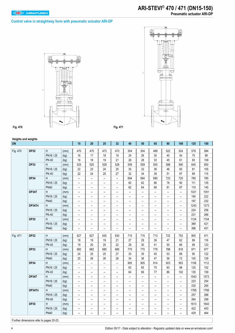
Heights and weightsDN 15 20 25 32 40 50 65 80 100 125 150
Fig. 470 DP32 H (mm) 470 470 473 473 504 504 489 522 524 579 584PN16 / 25 (kg) 16 17 18 19 24 26 30 40 54 75 99PN 40 (kg) 16 18 19 21 26 28 33 45 61 83 109
DP33 H (mm) 525 525 528 528 559 559 555 588 590 645 650PN16 / 25 (kg) 22 23 24 25 30 32 36 46 60 81 105PN 40 (kg) 22 24 25 27 32 34 39 51 67 89 115
DP34 H (mm) -- -- -- -- 694 694 690 723 725 780 785PN16 / 25 (kg) -- -- -- -- 60 62 66 76 90 111 135PN40 (kg) -- -- -- -- 62 64 69 81 97 119 145
DP34T H (mm) -- -- -- -- -- -- -- -- -- 1021 1051PN16 / 25 (kg) -- -- -- -- -- -- -- -- -- 190 222PN40 (kg) -- -- -- -- -- -- -- -- -- 197 232
DP34Tri H (mm) -- -- -- -- -- -- -- -- -- 1243 1273PN16 / 25 (kg) -- -- -- -- -- -- -- -- -- 224 256PN 40 (kg) -- -- -- -- -- -- -- -- -- 231 266
DP35 H (mm) -- -- -- -- -- -- -- -- -- 1124 1154PN16 / 25 (kg) -- -- -- -- -- -- -- -- -- 389 421PN40 (kg) -- -- -- -- -- -- -- -- -- 396 431
Fig. 471 DP32 H (mm) 627 627 630 630 715 715 713 722 752 905 911PN16 / 25 (kg) 18 19 19 21 27 29 39 47 62 89 116PN 40 (kg) 19 20 20 22 28 30 41 50 66 99 123
DP33 H (mm) 682 682 685 685 770 770 779 788 818 971 977PN16 / 25 (kg) 24 25 25 27 33 35 45 53 68 95 122PN40 (kg) 25 26 26 28 34 36 47 56 72 105 129
DP34 H (mm) -- -- -- -- 905 905 914 923 953 1106 1112PN16 / 25 (kg) -- -- -- -- 63 65 75 83 98 125 152PN 40 (kg) -- -- -- -- 64 66 77 86 102 135 159
DP34T H (mm) -- -- -- -- -- -- -- -- -- 1543 1573PN16 / 25 (kg) -- -- -- -- -- -- -- -- -- 223 254PN40 (kg) -- -- -- -- -- -- -- -- -- 230 265
DP34Tri H (mm) -- -- -- -- -- -- -- -- -- 1765 1795PN16 / 25 (kg) -- -- -- -- -- -- -- -- -- 257 288PN 40 (kg) -- -- -- -- -- -- -- -- -- 264 299
DP35 H (mm) -- -- -- -- -- -- -- -- -- 1613 1643PN16 / 25 (kg) -- -- -- -- -- -- -- -- -- 422 453PN40 (kg) -- -- -- -- -- -- -- -- -- 429 464
Further dimensions refer to pages 20-23.
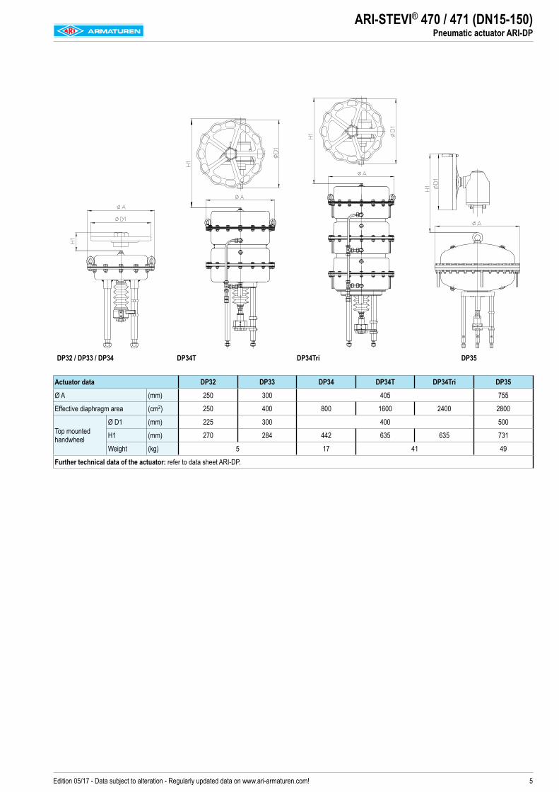
ARI-STEVI® 470 / 471 (DN15-150)Pneumatic actuator ARI-DP
Control valve in straightway form with pneumatic actuator ARI-DP
Fig. 470 Fig. 471
5Edition 05/17 - Data subject to alteration - Regularly updated data on www.ari-armaturen.com!
DP32 / DP33 / DP34 DP34T DP34Tri DP35
Actuator data DP32 DP33 DP34 DP34T DP34Tri DP35
Ø A (mm) 250 300 405 755
Effective diaphragm area (cm2) 250 400 800 1600 2400 2800
Top mounted handwheel
Ø D1 (mm) 225 300 400 500
H1 (mm) 270 284 442 635 635 731
Weight (kg) 5 17 41 49
Further technical data of the actuator: refer to data sheet ARI-DP.
ARI-STEVI® 470 / 471 (DN15-150)Pneumatic actuator ARI-DP
6 Edition 05/17 - Data subject to alteration - Regularly updated data on www.ari-armaturen.com!
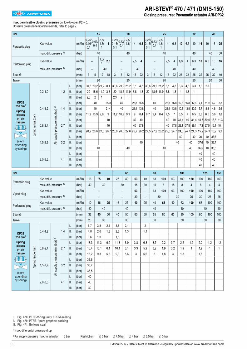
ARI-STEVI® 470 / 471 (DN15-150)Closing pressures: Pneumatic actuator ARI-DP32
max. permissible closing pressures on flow-to-open P2 = 0. Observe pressure-temperature-limits, refer to page 2.
DN 15 20 25 32 40
Parabolic plugKvs-value (m3/h)
0,25/ 0,16/ 0,1
0,63/ 0,4
2,5/ 1,6/ 1
40,25/ 0,16/ 0,1
0,63/ 0,4
2,5/ 1,6/
14 6,3
0,25/ 0,16/ 0,1
0,63/ 0,4
2,5/ 1,6/
14 6,3 10 6,3 10 16 10 16 25
max. diff. pressure 1) (bar) 40 40 40 40 40 30
Perforated plugKvs-value (m3/h) -- 1,6/
1 2,5 -- 2,5 4 -- 2,5 4 6,3 4 6,3 10 6,3 10 16
max. diff. pressure 1) (bar) -- 40 -- 40 -- 40 40 40
Seat-Ø (mm) 3 5 12 18 3 5 12 18 22 3 5 12 18 22 25 22 25 32 25 32 40Travel (mm) 20 20 20 20 20 30
DP32 250 cm2
Spring closes on air failure
(stem extending by spring)
Sprin
g ran
ge (b
ar)
0,2-1,0
Air s
upply
pres
sure
min.
(bar
) 2)
1,2I. (bar) 30,6 29,2 21,2 8,1 30,6 29,2 21,2 8,1 4,8 30,6 29,2 21,2 8,1 4,8 3,3 4,8 3,3 1,3 2,5II. (bar) 20 18,6 11,9 3,8 20 18,6 11,9 3,8 1,8 20 18,6 11,9 3,8 1,8 1 1,8 1III. (bar) 2,3 2 1 2,3 2 1
0,4-1,2 1,4I. (bar) 40 25,8 40 25,8 16,8 40 25,8 16,8 12,6 16,8 12,6 7,1 11,9 6,7 3,8II. (bar) 40 21,4 40 21,4 13,8 40 21,4 13,8 10,3 13,8 10,3 5,7 8,8 4,8 2,6III. (bar) 11,2 10,9 9,9 9 11,2 10,9 9,9 9 8,4 9,7 9,4 8,4 7,5 7 6,5 7 6,5 3,6 6,5 3,6 1,8
0,8-2,4 2,7I. (bar) 40 40 40 40 40 31,4 40 31,4 18,7 30,6 18,3 11,3II. (bar) 40 40 37,8 40 37,8 29,1 37,8 29,1 17,3 27,5 16,4 10,1III. (bar) 28,9 28,6 27,6 26,7 28,9 28,6 27,6 26,7 26,2 27,5 27,2 26,2 25,3 24,7 24,3 24,7 24,3 15,2 24,3 15,2 9,3
1,5-2,9 3,2I. (bar) 40 40 39 40 38,6II. (bar) 40 40 40 37,6 40 36,7III. (bar) 40 40 40 40 35,5 40 35,5
2,0-3,8 4,1I. (bar) 40 40II. (bar) 40 40III. (bar) 40 40
DN 50 65 80 100 125 150
Parabolic plugKvs-value (m3/h) 16 25 40 25 40 63 40 63 100 63 100 160 100 160 160
max. diff. pressure 1) (bar) 40 30 30 15 30 15 8 15 8 4 8 4 4
V-port plugKvs-value (m3/h) -- -- 63 -- 63 100 63 100 160 100 160 160
max. diff. pressure 1) (bar) -- -- 30 -- 30 30 25 30 25 25
Perforated plugKvs-value (m3/h) 10 16 25 16 25 40 25 40 63 40 63 100 63 100 100
max. diff. pressure 1) (bar) 40 40 40 40 40 40 40
Seat-Ø (mm) 32 40 50 40 50 65 50 65 80 65 80 100 80 100 100Travel (mm) 20 30 30 30 30 30 30
DP32 250 cm2
Spring closes on air failure
(stem extending by spring)
Sprin
g ran
ge (b
ar)
0,4-1,2
Air s
upply
pres
sure
min.
(bar
) 2)
1,4I. (bar) 6,7 3,8 2,1 3,8 2,1 2II. (bar) 4,8 2,6 1,3 2,6 1,3 1,1III. (bar) 3,6 1,8 1,8
0,8-2,4 2,7I. (bar) 18,3 11,3 6,9 11,3 6,9 3,8 6,8 3,7 2,2 3,7 2,2 1,2 2,2 1,2 1,2II. (bar) 16,4 10,1 6,1 10,1 6,1 3,3 5,9 3,2 1,9 3,2 1,9 1 1,9 1 1III. (bar) 15,2 9,3 5,6 9,3 5,6 3 5,6 3 1,8 3 1,8 1,5
1,5-2,9 3,2I. (bar) 38,6II. (bar) 36,7III. (bar) 35,5
2,0-3,8 4,1I. (bar) 40II. (bar) 40III. (bar) 40
I. Fig. 470: PTFE-V-ring unit / EPDM-sealing II. Fig. 470: PTFE- / pure graphite-packing III. Fig. 471: Bellows seal1) max. differential pressure drop2) Air supply pressure max. to actuator: 6 bar Restriction: a) 5 bar b) 4,5 bar c) 4 bar d) 3,5 bar e) 3 bar
7Edition 05/17 - Data subject to alteration - Regularly updated data on www.ari-armaturen.com!
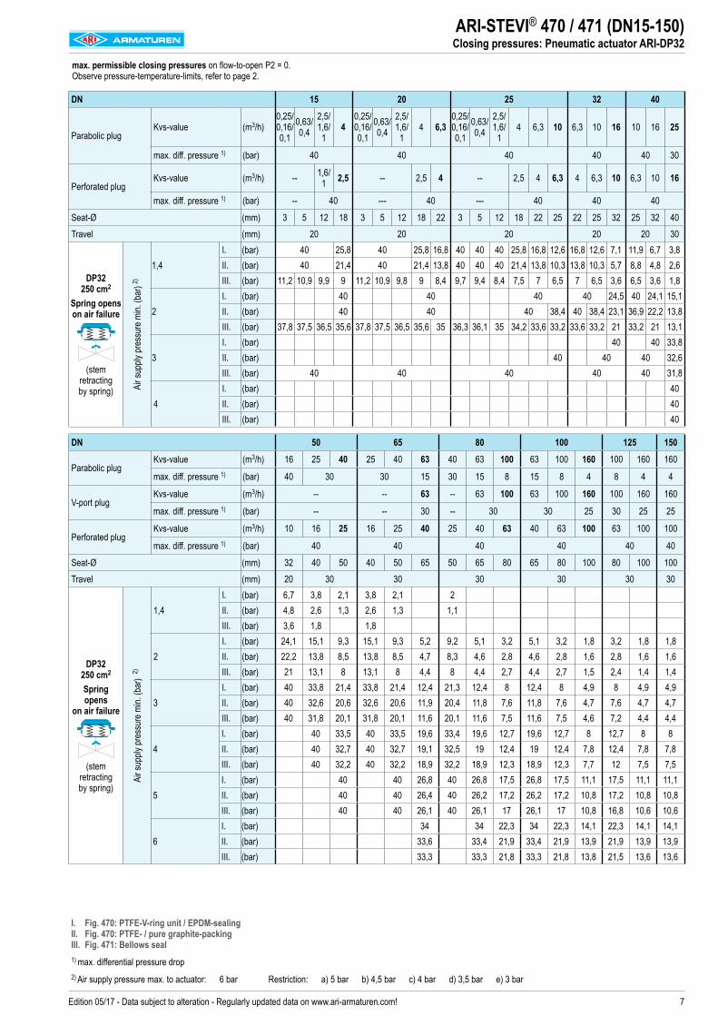
max. permissible closing pressures on flow-to-open P2 = 0. Observe pressure-temperature-limits, refer to page 2.
DN 15 20 25 32 40
Parabolic plugKvs-value (m3/h)
0,25/ 0,16/ 0,1
0,63/ 0,4
2,5/ 1,6/
14
0,25/ 0,16/ 0,1
0,63/ 0,4
2,5/ 1,6/
14 6,3
0,25/ 0,16/ 0,1
0,63/ 0,4
2,5/ 1,6/
14 6,3 10 6,3 10 16 10 16 25
max. diff. pressure 1) (bar) 40 40 40 40 40 30
Perforated plugKvs-value (m3/h) -- 1,6/
1 2,5 -- 2,5 4 -- 2,5 4 6,3 4 6,3 10 6,3 10 16
max. diff. pressure 1) (bar) -- 40 --- 40 --- 40 40 40
Seat-Ø (mm) 3 5 12 18 3 5 12 18 22 3 5 12 18 22 25 22 25 32 25 32 40Travel (mm) 20 20 20 20 20 30
DP32 250 cm2
Spring opens on air failure
(stem retracting by spring) Ai
r sup
ply pr
essu
re m
in. (b
ar) 2)
1,4I. (bar) 40 25,8 40 25,8 16,8 40 40 40 25,8 16,8 12,6 16,8 12,6 7,1 11,9 6,7 3,8II. (bar) 40 21,4 40 21,4 13,8 40 40 40 21,4 13,8 10,3 13,8 10,3 5,7 8,8 4,8 2,6III. (bar) 11,2 10,9 9,9 9 11,2 10,9 9,8 9 8,4 9,7 9,4 8,4 7,5 7 6,5 7 6,5 3,6 6,5 3,6 1,8
2I. (bar) 40 40 40 40 24,5 40 24,1 15,1II. (bar) 40 40 40 38,4 40 38,4 23,1 36,9 22,2 13,8III. (bar) 37,8 37,5 36,5 35,6 37,8 37,5 36,5 35,6 35 36,3 36,1 35 34,2 33,6 33,2 33,6 33,2 21 33,2 21 13,1
3I. (bar) 40 40 33,8II. (bar) 40 40 40 32,6III. (bar) 40 40 40 40 40 31,8
4I. (bar) 40II. (bar) 40III. (bar) 40
DN 50 65 80 100 125 150
Parabolic plugKvs-value (m3/h) 16 25 40 25 40 63 40 63 100 63 100 160 100 160 160
max. diff. pressure 1) (bar) 40 30 30 15 30 15 8 15 8 4 8 4 4
V-port plugKvs-value (m3/h) -- -- 63 -- 63 100 63 100 160 100 160 160
max. diff. pressure 1) (bar) -- -- 30 -- 30 30 25 30 25 25
Perforated plugKvs-value (m3/h) 10 16 25 16 25 40 25 40 63 40 63 100 63 100 100
max. diff. pressure 1) (bar) 40 40 40 40 40 40
Seat-Ø (mm) 32 40 50 40 50 65 50 65 80 65 80 100 80 100 100Travel (mm) 20 30 30 30 30 30 30
DP32 250 cm2
Spring opens
on air failure
(stem retracting by spring)
Air s
upply
pres
sure
min.
(bar
) 2)
1,4I. (bar) 6,7 3,8 2,1 3,8 2,1 2II. (bar) 4,8 2,6 1,3 2,6 1,3 1,1III. (bar) 3,6 1,8 1,8
2I. (bar) 24,1 15,1 9,3 15,1 9,3 5,2 9,2 5,1 3,2 5,1 3,2 1,8 3,2 1,8 1,8II. (bar) 22,2 13,8 8,5 13,8 8,5 4,7 8,3 4,6 2,8 4,6 2,8 1,6 2,8 1,6 1,6III. (bar) 21 13,1 8 13,1 8 4,4 8 4,4 2,7 4,4 2,7 1,5 2,4 1,4 1,4
3I. (bar) 40 33,8 21,4 33,8 21,4 12,4 21,3 12,4 8 12,4 8 4,9 8 4,9 4,9II. (bar) 40 32,6 20,6 32,6 20,6 11,9 20,4 11,8 7,6 11,8 7,6 4,7 7,6 4,7 4,7III. (bar) 40 31,8 20,1 31,8 20,1 11,6 20,1 11,6 7,5 11,6 7,5 4,6 7,2 4,4 4,4
4I. (bar) 40 33,5 40 33,5 19,6 33,4 19,6 12,7 19,6 12,7 8 12,7 8 8II. (bar) 40 32,7 40 32,7 19,1 32,5 19 12,4 19 12,4 7,8 12,4 7,8 7,8III. (bar) 40 32,2 40 32,2 18,9 32,2 18,9 12,3 18,9 12,3 7,7 12 7,5 7,5
5I. (bar) 40 40 26,8 40 26,8 17,5 26,8 17,5 11,1 17,5 11,1 11,1II. (bar) 40 40 26,4 40 26,2 17,2 26,2 17,2 10,8 17,2 10,8 10,8III. (bar) 40 40 26,1 40 26,1 17 26,1 17 10,8 16,8 10,6 10,6
6I. (bar) 34 34 22,3 34 22,3 14,1 22,3 14,1 14,1II. (bar) 33,6 33,4 21,9 33,4 21,9 13,9 21,9 13,9 13,9III. (bar) 33,3 33,3 21,8 33,3 21,8 13,8 21,5 13,6 13,6
ARI-STEVI® 470 / 471 (DN15-150)Closing pressures: Pneumatic actuator ARI-DP32
I. Fig. 470: PTFE-V-ring unit / EPDM-sealing II. Fig. 470: PTFE- / pure graphite-packing III. Fig. 471: Bellows seal1) max. differential pressure drop2) Air supply pressure max. to actuator: 6 bar Restriction: a) 5 bar b) 4,5 bar c) 4 bar d) 3,5 bar e) 3 bar
8 Edition 05/17 - Data subject to alteration - Regularly updated data on www.ari-armaturen.com!
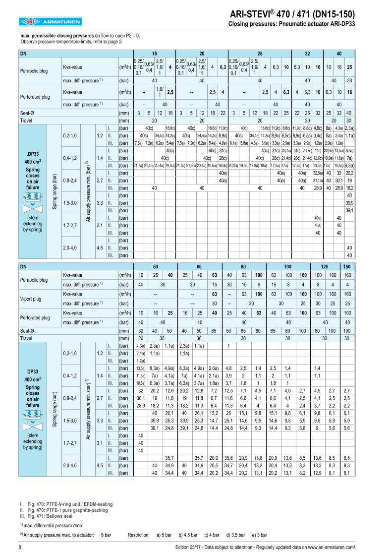
ARI-STEVI® 470 / 471 (DN15-150)Closing pressures: Pneumatic actuator ARI-DP33
max. permissible closing pressures on flow-to-open P2 = 0. Observe pressure-temperature-limits, refer to page 2.
DN 15 20 25 32 40
Parabolic plugKvs-value (m3/h)
0,25/ 0,16/ 0,1
0,63/ 0,4
2,5/ 1,6/ 1
40,25/ 0,16/ 0,1
0,63/ 0,4
2,5/ 1,6/
14 6,3
0,25/ 0,16/ 0,1
0,63/ 0,4
2,5/ 1,6/
14 6,3 10 6,3 10 16 10 16 25
max. diff. pressure 1) (bar) 40 40 40 40 40 30
Perforated plugKvs-value (m3/h) -- 1,6/
1 2,5 -- 2,5 4 -- 2,5 4 6,3 4 6,3 10 6,3 10 16
max. diff. pressure 1) (bar) -- 40 -- 40 -- 40 40 40Seat-Ø (mm) 3 5 12 18 3 5 12 18 22 3 5 12 18 22 25 22 25 32 25 32 40Travel (mm) 20 20 20 20 20 30
.DP33400 cm2
Spring closes on air failure
(stem extending by spring)
Sprin
g ran
ge (b
ar)
0,2-1,0
Air s
upply
pres
sure
min.
(bar
) 2)
1,2I. (bar) 40c) 18,6c) 40c) 18,6c) 11,9c) 40c) 18,6c) 11,9c) 8,8c) 11,9c) 8,8c) 4,8c) 8a) 4,3a) 2,3a)II. (bar) 40c) 34,4c) 14,2c) 40c) 34,4c) 14,2c) 8,9c) 40c) 34,4c) 14,2c) 8,9c) 6,5c) 8,9c) 6,5c) 3,4c) 5a) 2,4a) 1,1a)III. (bar) 7,5a) 7,2a) 6,2a) 5,4a) 7,5a) 7,2a) 6,2a) 5,4a) 4,8a) 6,1a) 5,8a) 4,8a) 3,9a) 3,3a) 2,9a) 3,3a) 2,9a) 1,2a) 2,9a) 1,2a)
0,4-1,2 1,4I. (bar) 40c) 40c) 31c) 40c) 31c) 23,7c) 31c) 23,7c) 14c) 22,9a) 13,5a) 8,3a)II. (bar) 40c) 40c) 28c) 40c) 28c) 21,4c) 28c) 21,4c) 12,6c) 19,9a) 11,6a) 7a)III. (bar) 21,7a) 21,4a) 20,4a) 19,5a) 21,7a) 21,4a) 20,4a) 19,5a) 18,9a) 20,2a) 19,9a) 18,9a) 18a) 17,5a) 17a) 17,5a) 17a) 10,5a) 17a) 10,5a) 6,3a)
0,8-2,4 2,7I. (bar) 40a) 40a) 40a) 32,5a) 40 32 20,2II. (bar) 40a) 40a) 40a) 31,1a) 40 30,1 19III. (bar) 40 40 40 40 28,9 40 28,9 18,2
1,5-3,0 3,3I. (bar) 40II. (bar) 39,9III. (bar) 39,1
1,7-2,7 3,1I. (bar) 40a) 40II. (bar) 40a) 40III. (bar) 40 40
2,0-4,0 4,5I. (bar)II. (bar) 40III. (bar) 40
DN 50 65 80 100 125 150
Parabolic plugKvs-value (m3/h) 16 25 40 25 40 63 40 63 100 63 100 160 100 160 160
max. diff. pressure 1) (bar) 40 30 30 15 30 15 8 15 8 4 8 4 4
V-port plugKvs-value (m3/h) -- -- 63 -- 63 100 63 100 160 100 160 160
max. diff. pressure 1) (bar) -- --- 30 -- 30 30 25 30 25 25
Perforated plugKvs-value (m3/h) 10 16 25 16 25 40 25 40 63 40 63 100 63 100 100
max. diff. pressure 1) (bar) 40 40 40 40 40 40 40Seat-Ø (mm) 32 40 50 40 50 65 50 65 80 65 80 100 80 100 100Travel (mm) 20 30 30 30 30 30 30
DP33400 cm2
Spring closes on air failure
(stem extending by spring)
Sprin
g ran
ge (b
ar)
0,2-1,0
Air s
upply
pres
sure
min.
(bar
) 2)
1,2I. (bar) 4,3a) 2,3a) 1,1a) 2,3a) 1,1a) 1II. (bar) 2,4a) 1,1a) 1,1a)III. (bar) 1,2a)
0,4-1,2 1,4I. (bar) 13,5a) 8,3a) 4,9a) 8,3a) 4,9a) 2,6a) 4,8 2,5 1,4 2,5 1,4 1,4II. (bar) 11,6a) 7a) 4,1a) 7a) 4,1a) 2,1a) 3,9 2 1,1 2 1,1 1,1III. (bar) 10,5a) 6,3a) 3,7a) 6,3a) 3,7a) 1,8a) 3,7 1,8 1 1,8 1
0,8-2,4 2,7I. (bar) 32 20,2 12,6 20,2 12,6 7,2 12,5 7,1 4,5 7,1 4,5 2,7 4,5 2,7 2,7II. (bar) 30,1 19 11,8 19 11,8 6,7 11,6 6,6 4,1 6,6 4,1 2,5 4,1 2,5 2,5III. (bar) 28,9 18,2 11,3 18,2 11,3 6,4 11,3 6,4 4 6,4 4 2,4 3,7 2,2 2,2
1,5-3,0 3,3 I. (bar) 40 26,1 40 26,1 15,2 26 15,1 9,8 15,1 9,8 6,1 9,8 6,1 6,1II. (bar) 39,9 25,3 39,9 25,3 14,7 25,1 14,6 9,5 14,6 9,5 5,9 9,5 5,9 5,9III. (bar) 39,1 24,8 39,1 24,8 14,4 24,8 14,4 9,3 14,4 9,3 5,8 9 5,6 5,6
1,7-2,7 3,1I. (bar) 40II. (bar) 40III. (bar) 40
2,0-4,0 4,5I. (bar) 35,7 35,7 20,9 35,6 20,9 13,6 20,9 13,6 8,5 13,6 8,5 8,5II. (bar) 40 34,9 40 34,9 20,5 34,7 20,4 13,3 20,4 13,3 8,3 13,3 8,3 8,3III. (bar) 40 34,4 40 34,4 20,2 34,4 20,2 13,1 20,2 13,1 8,2 12,9 8,1 8,1
I. Fig. 470: PTFE-V-ring unit / EPDM-sealing II. Fig. 470: PTFE- / pure graphite-packing III. Fig. 471: Bellows seal1) max. differential pressure drop2) Air supply pressure max. to actuator: 6 bar Restriction: a) 5 bar b) 4,5 bar c) 4 bar d) 3,5 bar e) 3 bar
9Edition 05/17 - Data subject to alteration - Regularly updated data on www.ari-armaturen.com!
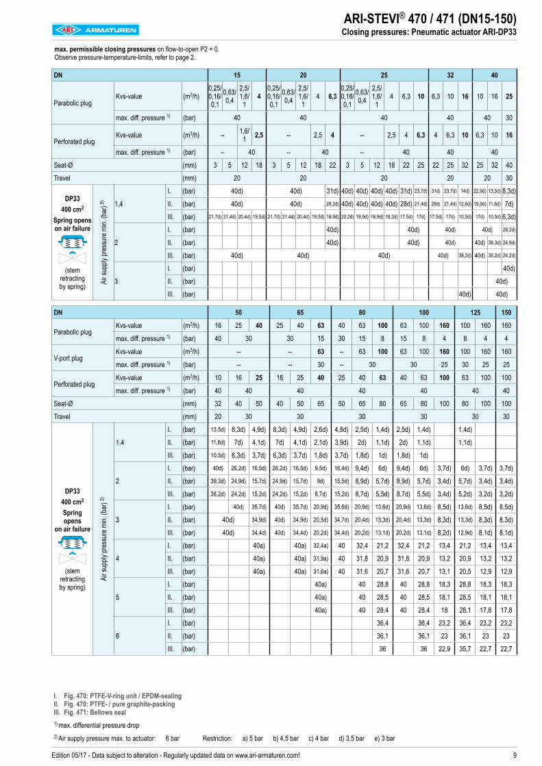
ARI-STEVI® 470 / 471 (DN15-150)Closing pressures: Pneumatic actuator ARI-DP33
max. permissible closing pressures on flow-to-open P2 = 0. Observe pressure-temperature-limits, refer to page 2.
DN 15 20 25 32 40
Parabolic plugKvs-value (m3/h)
0,25/ 0,16/ 0,1
0,63/ 0,4
2,5/ 1,6/
14
0,25/ 0,16/ 0,1
0,63/ 0,4
2,5/ 1,6/
14 6,3
0,25/ 0,16/ 0,1
0,63/ 0,4
2,5/ 1,6/
14 6,3 10 6,3 10 16 10 16 25
max. diff. pressure 1) (bar) 40 40 40 40 40 30
Perforated plugKvs-value (m3/h) -- 1,6/
1 2,5 -- 2,5 4 -- 2,5 4 6,3 4 6,3 10 6,3 10 16
max. diff. pressure 1) (bar) -- 40 -- 40 -- 40 40 40
Seat-Ø (mm) 3 5 12 18 3 5 12 18 22 3 5 12 18 22 25 22 25 32 25 32 40
Travel (mm) 20 20 20 20 20 30
DP33400 cm2
Spring opens on air failure
(stem retracting by spring) Ai
r sup
ply pr
essu
re m
in. (b
ar) 2) 1,4
I. (bar) 40d) 40d) 31d) 40d) 40d) 40d) 40d) 31d) 23,7d) 31d) 23,7d) 14d) 22,9d) 13,5d) 8,3d)
II. (bar) 40d) 40d) 28,2d) 40d) 40d) 40d) 40d) 28d) 21,4d) 28d) 21,4d) 12,6d) 19,9d) 11,6d) 7d)
III. (bar) 21,7d) 21,4d) 20,4d) 19,5d) 21,7d) 21,4d) 20,4d) 19,5d) 18,9d) 20,2d) 19,9d) 18,9d) 18,2d) 17,5d) 17d) 17,5d) 17d) 10,5d) 17d) 10,5d) 6,3d)
2
I. (bar) 40d) 40d) 40d) 40d) 26,2d)
II. (bar) 40d) 40d) 40d) 40d) 39,3d) 24,9d)
III. (bar) 40d) 40d) 40d) 40d) 38,2d) 40d) 38,2d) 24,2d)
3
I. (bar) 40d)
II. (bar) 40d)
III. (bar) 40d) 40d)
DN 50 65 80 100 125 150
Parabolic plugKvs-value (m3/h) 16 25 40 25 40 63 40 63 100 63 100 160 100 160 160
max. diff. pressure 1) (bar) 40 30 30 15 30 15 8 15 8 4 8 4 4
V-port plugKvs-value (m3/h) -- -- 63 -- 63 100 63 100 160 100 160 160
max. diff. pressure 1) (bar) -- -- 30 -- 30 30 25 30 25 25
Perforated plugKvs-value (m3/h) 10 16 25 16 25 40 25 40 63 40 63 100 63 100 100
max. diff. pressure 1) (bar) 40 40 40 40 40 40 40
Seat-Ø (mm) 32 40 50 40 50 65 50 65 80 65 80 100 80 100 100
Travel (mm) 20 30 30 30 30 30 30
DP33400 cm2
Spring opens
on air failure
(stem retracting by spring)
Air s
upply
pres
sure
min.
(bar
) 2)
1,4
I. (bar) 13,5d) 8,3d) 4,9d) 8,3d) 4,9d) 2,6d) 4,8d) 2,5d) 1,4d) 2,5d) 1,4d) 1,4d)
II. (bar) 11,6d) 7d) 4,1d) 7d) 4,1d) 2,1d) 3,9d) 2d) 1,1d) 2d) 1,1d) 1,1d)
III. (bar) 10,5d) 6,3d) 3,7d) 6,3d) 3,7d) 1,8d) 3,7d) 1,8d) 1d) 1,8d) 1d)
2
I. (bar) 40d) 26,2d) 16,5d) 26,2d) 16,5d) 9,5d) 16,4d) 9,4d) 6d) 9,4d) 6d) 3,7d) 6d) 3,7d) 3,7d)
II. (bar) 39,3d) 24,9d) 15,7d) 24,9d) 15,7d) 9d) 15,5d) 8,9d) 5,7d) 8,9d) 5,7d) 3,4d) 5,7d) 3,4d) 3,4d)
III. (bar) 38,2d) 24,2d) 15,2d) 24,2d) 15,2d) 8,7d) 15,2d) 8,7d) 5,5d) 8,7d) 5,5d) 3,4d) 5,2d) 3,2d) 3,2d)
3
I. (bar) 40d) 35,7d) 40d) 35,7d) 20,9d) 35,6d) 20,9d) 13,6d) 20,9d) 13,6d) 8,5d) 13,6d) 8,5d) 8,5d)
II. (bar) 40d) 34,9d) 40d) 34,9d) 20,5d) 34,7d) 20,4d) 13,3d) 20,4d) 13,3d) 8,3d) 13,3d) 8,3d) 8,3d)
III. (bar) 40d) 34,4d) 40d) 34,4d) 20,2d) 34,4d) 20,2d) 13,1d) 20,2d) 13,1d) 8,2d) 12,9d) 8,1d) 8,1d)
4
I. (bar) 40a) 40a) 32,4a) 40 32,4 21,2 32,4 21,2 13,4 21,2 13,4 13,4
II. (bar) 40a) 40a) 31,9a) 40 31,8 20,9 31,8 20,9 13,2 20,9 13,2 13,2
III. (bar) 40a) 40a) 31,6a) 40 31,6 20,7 31,6 20,7 13,1 20,5 12,9 12,9
5
I. (bar) 40a) 40 28,8 40 28,8 18,3 28,8 18,3 18,3
II. (bar) 40a) 40 28,5 40 28,5 18,1 28,5 18,1 18,1
III. (bar) 40a) 40 28,4 40 28,4 18 28,1 17,8 17,8
6
I. (bar) 36,4 36,4 23,2 36,4 23,2 23,2
II. (bar) 36,1 36,1 23 36,1 23 23
III. (bar) 36 36 22,9 35,7 22,7 22,7
I. Fig. 470: PTFE-V-ring unit / EPDM-sealing II. Fig. 470: PTFE- / pure graphite-packing III. Fig. 471: Bellows seal1) max. differential pressure drop2) Air supply pressure max. to actuator: 6 bar Restriction: a) 5 bar b) 4,5 bar c) 4 bar d) 3,5 bar e) 3 bar
10 Edition 05/17 - Data subject to alteration - Regularly updated data on www.ari-armaturen.com!
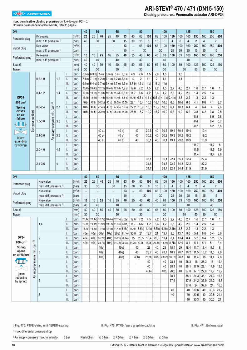
ARI-STEVI® 470 / 471 (DN15-150)Closing pressures: Pneumatic actuator ARI-DP34
max. permissible closing pressures on flow-to-open P2 = 0. Observe pressure-temperature-limits, refer to page 2.
DN 40 50 65 80 100 125 150
Parabolic plugKvs-value (m3/h) 25 25 40 25 40 63 40 63 100 63 100 160 100 160 250 160 250 400max. diff. pressure 1) (bar) 40 30 30 15 30 15 8 15 8 4 8 4 2 4 2
V-port plugKvs-value (m3/h) -- -- -- 63 -- 63 100 63 100 160 100 160 250 160 250 400max. diff. pressure 1) (bar) -- -- -- 30 -- 30 30 25 30 25 15 25 15
Perforated plugKvs-value (m3/h) 16 16 25 16 25 40 25 40 63 40 63 100 63 100 160 100 160 250max. diff. pressure 1) (bar) 40 40 40 40 40 40 40
Seat-Ø (mm) 40 40 50 40 50 65 50 65 80 65 80 100 80 100 125 100 125 150Travel (mm) 30 30 30 30 30 30 50 30 50
DP34 800 cm2
Spring closes on air failure
(stem extending by spring)
Sprin
g ran
ge (b
ar)
0,2-1,0
Air s
upply
pres
sure
min.
(bar
) 2)
1,2I. (bar) 8,3 e) 8,3 e) 5 e) 8,3 e) 5 e) 2,6 e) 4,9 2,6 1,5 2,6 1,5 1,5II. (bar) 7,1 e) 7,1 e) 4,2 e) 7,1 e) 4,2 e) 2,1 e) 4 2 1,1 2 1,1 1,1III. (bar) 6,4 e) 6,4 e) 3,7 e) 6,4 e) 3,7 e) 1,9 e) 3,7 b) 1,9 b) 1 b) 1,9 b) 1 b)
0,4-1,2 1,4I. (bar) 20,4d) 20,4d) 12,7d) 20,4d) 12,7d) 7,2 d) 12,6 7,2 4,5 7,2 4,5 2,7 4,5 2,7 1,6 2,7 1,6 1II. (bar) 19,1d) 19,1d) 11,9d) 19,1d) 11,9d) 6,8 d) 11,7 6,6 4,2 6,6 4,2 2,5 4,2 2,5 1,4 2,5 1,4III. (bar) 18,4d) 18,4d) 11,4d) 18,4d) 11,4d) 6,5 d) 11,4b) 6,5 b) 4,1 b) 6,5 b) 4,1 b) 2,4 b) 3,8 2,2 1,3 2,2 1,3
0,8-2,4 2,7I. (bar) 40 b) 40 b) 28,2b) 40 b) 28,2b) 16,5b) 28,1 16,4 10,6 16,4 10,6 6,6 10,6 6,6 4,1 6,6 4,1 2,7II. (bar) 40 b) 40 b) 27,4b) 40 b) 27,4b) 16 b) 27,2 15,9 10,3 15,9 10,3 6,4 10,3 6,4 4 6,4 4 2,6III. (bar) 40 b) 40 b) 26,9b) 40 b) 26,9b) 15,7b) 26,9 15,7 10,2 15,7 10,2 6,3 9,9 6,2 3,8 6,2 3,8 2,5
1,5-3,0 3,3I. (bar) 8,5 8,5 5,8II. (bar) 8,4 8,4 5,7III. (bar) 8,2 8,2 5,6
2,1-3,0 3,3I. (bar) 40 a) 40 a) 40 30,5 40 30,5 19,4 30,5 19,4 19,4II. (bar) 40 a) 40 a) 40 30,2 40 30,2 19,2 30,2 19,2 19,2III. (bar) 40 a) 40 a) 40 30,1 40 30,1 19,1 29,8 18,9 18,9
2,0-4,0 4,5I. (bar) 11,7 11,7 8II. (bar) 11,5 11,5 7,9III. (bar) 11,4 11,4 7,8
2,4-3,6 4I. (bar) 35,1 35,1 22,4 35,1 22,4 22,4II. (bar) 34,8 34,8 22,2 34,8 22,2 22,2III. (bar) 34,7 34,7 22,1 34,4 21,9 21,9
DN 40 50 65 80 100 125 150
Parabolic plugKvs-value (m3/h) 25 25 40 25 40 63 40 63 100 63 100 160 100 160 250 160 250 400max. diff. pressure 1) (bar) 30 30 30 15 30 15 8 15 8 4 8 4 2 4 2
V-port plugKvs-value (m3/h) -- -- -- 63 -- 63 100 63 100 160 100 160 250 160 250 400max. diff. pressure 1) (bar) -- -- -- 30 -- 30 30 25 30 25 15 25 15
Perforated plugKvs-value (m3/h) 16 16 25 16 25 40 25 40 63 40 63 100 63 100 160 100 160 250max. diff. pressure 1) (bar) 40 40 40 40 40 40 40
Seat-Ø (mm) 40 40 50 40 50 65 50 65 80 65 80 100 80 100 125 100 125 150Travel (mm) 30 30 30 30 30 30 50 30 50
DP34 800 cm2
Spring opens
on air failure
(stem retracting by spring)
Air s
upply
pres
sure
min.
(bar
) 2)
1,4I. (bar) 20,4e) 20,4e) 12,7e) 20,4e) 12,7e) 7,2e) 12,6 7,2 4,5 7,2 4,5 2,7 4,5 2,7 1,6 2,7 1,6 1II. (bar) 19,1e) 19,1e) 11,9e) 19,1e) 11,9e) 6,8e) 11,7 6,6 4,2 6,6 4,2 2,5 4,2 2,5 1,4 2,5 1,4III. (bar) 18,4e) 18,4e) 11,4e) 18,4e) 11,4e) 6,5e) 11,4b) 6,5b) 4,1b) 6,5b) 4,1b) 2,4b) 3,8 2,2 1,3 2,2 1,3
2I. (bar) 40e) 40e) 36e) 40e) 36e) 21,1e) 35,9 21 13,7 21 13,7 8,6 13,7 8,6 5,4 8,6 5,4 3,6II. (bar) 40e) 40e) 35,2e) 40e) 35,2e) 20,6e) 35 20,5 13,4 20,5 13,4 8,4 13,4 8,4 5,2 8,4 5,2 3,5III. (bar) 40e) 40e) 34,7e) 40e) 34,7e) 20,3e) 34,7b) 20,3b) 13,2b) 20,3b) 13,2b) 8,3b) 12,9 8,1 5,1 8,1 5,1 3,4
3I. (bar) 40e) 40e) 40 29 40 29 18,4 29 18,4 11,7 18,4 11,7 8II. (bar) 40e) 40e) 40 28,7 40 28,7 18,2 28,7 18,2 11,5 18,2 11,5 7,9III. (bar) 40e) 40e) 40b) 28,5b) 40b) 28,5b) 18,1b) 28,3 18 11,4 18 11,4 7,8
4I. (bar) 40 40 28,3 40 28,3 18 28,3 18 12,4II. (bar) 40 40 28,1 40 28,1 17,9 28,1 17,9 12,3III. (bar) 40b) 40b) 28b) 40 27,8 17,7 27,8 17,7 12,2
5I. (bar) 38,1 38,1 24,3 38,1 24,3 16,8II. (bar) 37,9 37,9 24,2 37,9 24,2 16,7III. (bar) 37,6 24 37,6 24 16,6
6I. (bar) 40 40 30,6 40 30,6 21,2II. (bar) 40 40 30,5 40 30,5 21,1III. (bar) 40 30,3 40 30,3 21
I. Fig. 470: PTFE-V-ring unit / EPDM-sealing II. Fig. 470: PTFE- / pure graphite-packing III. Fig. 471: Bellows seal1) max. differential pressure drop2) Air supply pressure max. to actuator: 6 bar Restriction: a) 5 bar b) 4,5 bar c) 4 bar d) 3,5 bar e) 3 bar
11Edition 05/17 - Data subject to alteration - Regularly updated data on www.ari-armaturen.com!
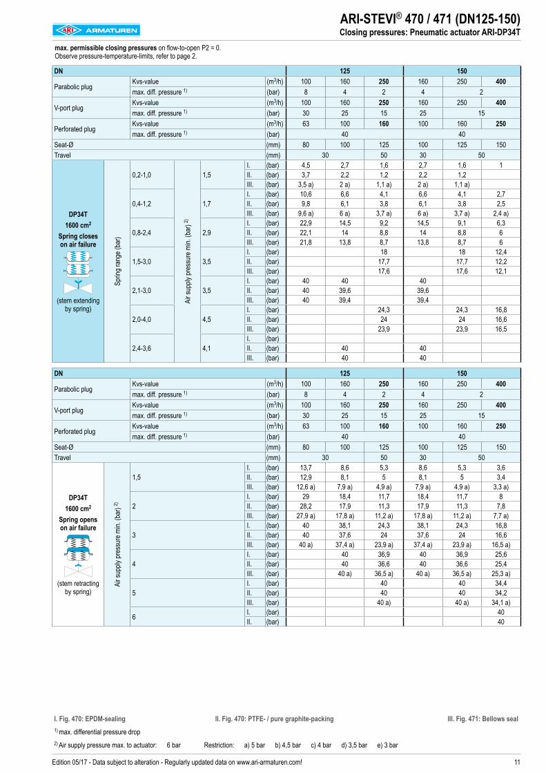
max. permissible closing pressures on flow-to-open P2 = 0. Observe pressure-temperature-limits, refer to page 2.
DN 125 150
Parabolic plugKvs-value (m3/h) 100 160 250 160 250 400max. diff. pressure 1) (bar) 8 4 2 4 2
V-port plugKvs-value (m3/h) 100 160 250 160 250 400max. diff. pressure 1) (bar) 30 25 15 25 15
Perforated plugKvs-value (m3/h) 63 100 160 100 160 250max. diff. pressure 1) (bar) 40 40
Seat-Ø (mm) 80 100 125 100 125 150Travel (mm) 30 50 30 50
DP34T 1600 cm2
Spring closes on air failure
(stem extending by spring)
Sprin
g ran
ge (b
ar)
0,2-1,0Ai
r sup
ply pr
essu
re m
in. (b
ar) 2)
1,5I. (bar) 4,5 2,7 1,6 2,7 1,6 1II. (bar) 3,7 2,2 1,2 2,2 1,2III. (bar) 3,5 a) 2 a) 1,1 a) 2 a) 1,1 a)
0,4-1,2 1,7I. (bar) 10,6 6,6 4,1 6,6 4,1 2,7II. (bar) 9,8 6,1 3,8 6,1 3,8 2,5III. (bar) 9,6 a) 6 a) 3,7 a) 6 a) 3,7 a) 2,4 a)
0,8-2,4 2,9I. (bar) 22,9 14,5 9,2 14,5 9,1 6,3II. (bar) 22,1 14 8,8 14 8,8 6III. (bar) 21,8 13,8 8,7 13,8 8,7 6
1,5-3,0 3,5I. (bar) 18 18 12,4II. (bar) 17,7 17,7 12,2III. (bar) 17,6 17,6 12,1
2,1-3,0 3,5I. (bar) 40 40 40II. (bar) 40 39,6 39,6III. (bar) 40 39,4 39,4
2,0-4,0 4,5I. (bar) 24,3 24,3 16,8II. (bar) 24 24 16,6III. (bar) 23,9 23,9 16,5
2,4-3,6 4,1I. (bar)II. (bar) 40 40III. (bar) 40 40
DN 125 150
Parabolic plugKvs-value (m3/h) 100 160 250 160 250 400max. diff. pressure 1) (bar) 8 4 2 4 2
V-port plugKvs-value (m3/h) 100 160 250 160 250 400max. diff. pressure 1) (bar) 30 25 15 25 15
Perforated plugKvs-value (m3/h) 63 100 160 100 160 250max. diff. pressure 1) (bar) 40 40
Seat-Ø (mm) 80 100 125 100 125 150Travel (mm) 30 50 30 50
DP34T 1600 cm2
Spring opens on air failure
(stem retracting by spring)
Air s
upply
pres
sure
min.
(bar
) 2)
1,5I. (bar) 13,7 8,6 5,3 8,6 5,3 3,6II. (bar) 12,9 8,1 5 8,1 5 3,4III. (bar) 12,6 a) 7,9 a) 4,9 a) 7,9 a) 4,9 a) 3,3 a)
2I. (bar) 29 18,4 11,7 18,4 11,7 8II. (bar) 28,2 17,9 11,3 17,9 11,3 7,8 III. (bar) 27,9 a) 17,8 a) 11,2 a) 17,8 a) 11,2 a) 7,7 a)
3I. (bar) 40 38,1 24,3 38,1 24,3 16,8II. (bar) 40 37,6 24 37,6 24 16,6 III. (bar) 40 a) 37,4 a) 23,9 a) 37,4 a) 23,9 a) 16,5 a)
4I. (bar) 40 36,9 40 36,9 25,6II. (bar) 40 36,6 40 36,6 25,4III. (bar) 40 a) 36,5 a) 40 a) 36,5 a) 25,3 a)
5I. (bar) 40 40 34,4II. (bar) 40 40 34,2III. (bar) 40 a) 40 a) 34,1 a)
6 I. (bar) 40II. (bar) 40
ARI-STEVI® 470 / 471 (DN125-150)Closing pressures: Pneumatic actuator ARI-DP34T
I. Fig. 470: EPDM-sealing II. Fig. 470: PTFE- / pure graphite-packing III. Fig. 471: Bellows seal1) max. differential pressure drop2) Air supply pressure max. to actuator: 6 bar Restriction: a) 5 bar b) 4,5 bar c) 4 bar d) 3,5 bar e) 3 bar
12 Edition 05/17 - Data subject to alteration - Regularly updated data on www.ari-armaturen.com!
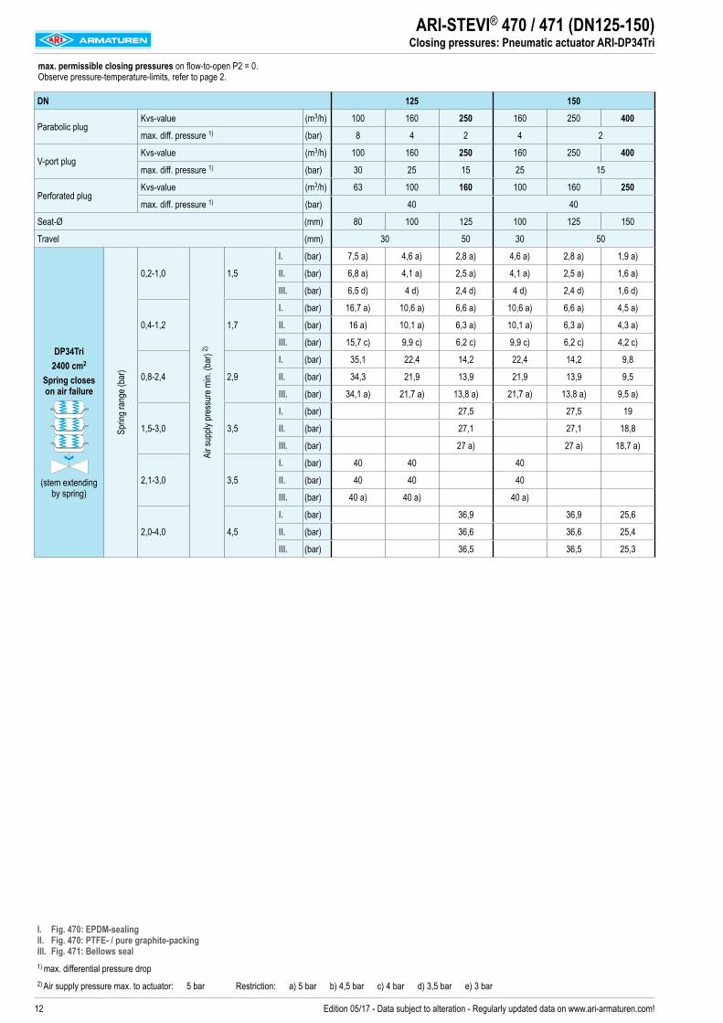
ARI-STEVI® 470 / 471 (DN125-150)Closing pressures: Pneumatic actuator ARI-DP34Tri
max. permissible closing pressures on flow-to-open P2 = 0. Observe pressure-temperature-limits, refer to page 2.
DN 125 150
Parabolic plugKvs-value (m3/h) 100 160 250 160 250 400
max. diff. pressure 1) (bar) 8 4 2 4 2
V-port plugKvs-value (m3/h) 100 160 250 160 250 400
max. diff. pressure 1) (bar) 30 25 15 25 15
Perforated plugKvs-value (m3/h) 63 100 160 100 160 250
max. diff. pressure 1) (bar) 40 40
Seat-Ø (mm) 80 100 125 100 125 150
Travel (mm) 30 50 30 50
DP34Tri
2400 cm2
Spring closes on air failure
(stem extending by spring)
Sprin
g ran
ge (b
ar)
0,2-1,0
Air s
upply
pres
sure
min.
(bar
) 2)
1,5
I. (bar) 7,5 a) 4,6 a) 2,8 a) 4,6 a) 2,8 a) 1,9 a)
II. (bar) 6,8 a) 4,1 a) 2,5 a) 4,1 a) 2,5 a) 1,6 a)
III. (bar) 6,5 d) 4 d) 2,4 d) 4 d) 2,4 d) 1,6 d)
0,4-1,2 1,7
I. (bar) 16,7 a) 10,6 a) 6,6 a) 10,6 a) 6,6 a) 4,5 a)
II. (bar) 16 a) 10,1 a) 6,3 a) 10,1 a) 6,3 a) 4,3 a)
III. (bar) 15,7 c) 9,9 c) 6,2 c) 9,9 c) 6,2 c) 4,2 c)
0,8-2,4 2,9
I. (bar) 35,1 22,4 14,2 22,4 14,2 9,8
II. (bar) 34,3 21,9 13,9 21,9 13,9 9,5
III. (bar) 34,1 a) 21,7 a) 13,8 a) 21,7 a) 13,8 a) 9,5 a)
1,5-3,0 3,5
I. (bar) 27,5 27,5 19
II. (bar) 27,1 27,1 18,8
III. (bar) 27 a) 27 a) 18,7 a)
2,1-3,0 3,5
I. (bar) 40 40 40
II. (bar) 40 40 40
III. (bar) 40 a) 40 a) 40 a)
2,0-4,0 4,5
I. (bar) 36,9 36,9 25,6
II. (bar) 36,6 36,6 25,4
III. (bar) 36,5 36,5 25,3
I. Fig. 470: EPDM-sealing II. Fig. 470: PTFE- / pure graphite-packing III. Fig. 471: Bellows seal1) max. differential pressure drop2) Air supply pressure max. to actuator: 5 bar Restriction: a) 5 bar b) 4,5 bar c) 4 bar d) 3,5 bar e) 3 bar
13Edition 05/17 - Data subject to alteration - Regularly updated data on www.ari-armaturen.com!
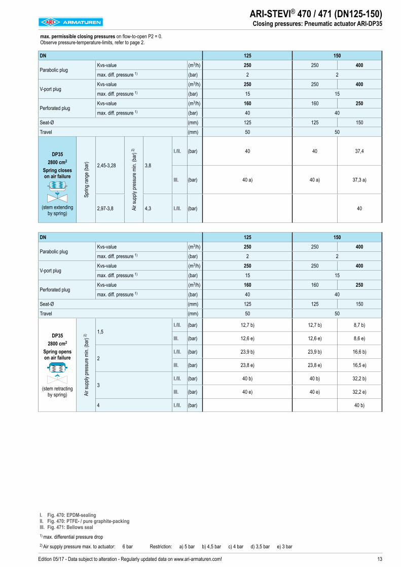
ARI-STEVI® 470 / 471 (DN125-150)Closing pressures: Pneumatic actuator ARI-DP35
max. permissible closing pressures on flow-to-open P2 = 0. Observe pressure-temperature-limits, refer to page 2.
DN 125 150
Parabolic plugKvs-value (m3/h) 250 250 400
max. diff. pressure 1) (bar) 2 2
V-port plugKvs-value (m3/h) 250 250 400
max. diff. pressure 1) (bar) 15 15
Perforated plugKvs-value (m3/h) 160 160 250
max. diff. pressure 1) (bar) 40 40
Seat-Ø (mm) 125 125 150
Travel (mm) 50 50
DP35 2800 cm2
Spring closes on air failure
(stem extending by spring)
Sprin
g ran
ge (b
ar)
2,45-3,28
Air s
upply
pres
sure
min.
(bar
) 2)
3,8
I./II. (bar) 40 40 37,4
III. (bar) 40 a) 40 a) 37,3 a)
2,97-3,8 4,3 I./II. (bar) 40
DN 125 150
Parabolic plugKvs-value (m3/h) 250 250 400max. diff. pressure 1) (bar) 2 2
V-port plugKvs-value (m3/h) 250 250 400
max. diff. pressure 1) (bar) 15 15
Perforated plugKvs-value (m3/h) 160 160 250
max. diff. pressure 1) (bar) 40 40
Seat-Ø (mm) 125 125 150
Travel (mm) 50 50
DP35 2800 cm2
Spring opens on air failure
(stem retracting by spring) Ai
r sup
ply pr
essu
re m
in. (b
ar) 2)
1,5I./II. (bar) 12,7 b) 12,7 b) 8,7 b)
III. (bar) 12,6 e) 12,6 e) 8,6 e)
2I./II. (bar) 23,9 b) 23,9 b) 16,6 b)
III. (bar) 23,8 e) 23,8 e) 16,5 e)
3I./II. (bar) 40 b) 40 b) 32,2 b)
III. (bar) 40 e) 40 e) 32,2 e)
4 I./II. (bar) 40 b)
I. Fig. 470: EPDM-sealing II. Fig. 470: PTFE- / pure graphite-packing III. Fig. 471: Bellows seal1) max. differential pressure drop2) Air supply pressure max. to actuator: 6 bar Restriction: a) 5 bar b) 4,5 bar c) 4 bar d) 3,5 bar e) 3 bar
14 Edition 05/17 - Data subject to alteration - Regularly updated data on www.ari-armaturen.com!
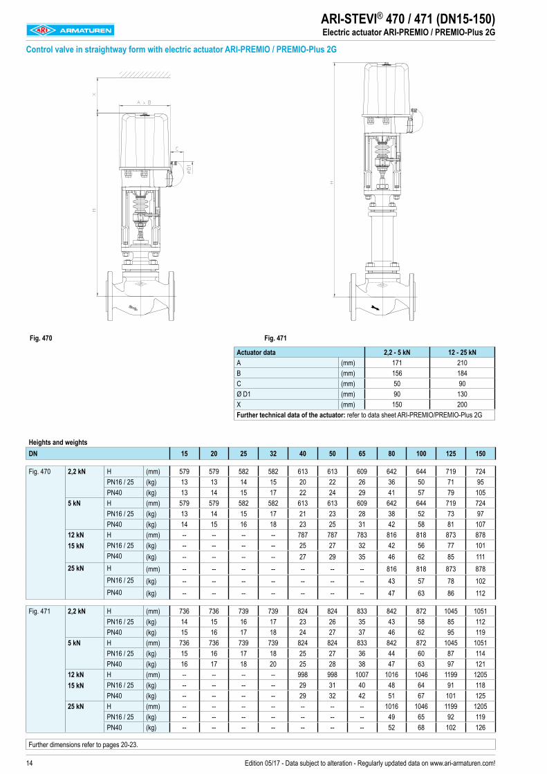
ARI-STEVI® 470 / 471 (DN15-150)Electric actuator ARI-PREMIO / PREMIO-Plus 2G
Heights and weightsDN 15 20 25 32 40 50 65 80 100 125 150
Fig. 470 2,2 kN H (mm) 579 579 582 582 613 613 609 642 644 719 724PN16 / 25 (kg) 13 13 14 15 20 22 26 36 50 71 95PN40 (kg) 13 14 15 17 22 24 29 41 57 79 105
5 kN H (mm) 579 579 582 582 613 613 609 642 644 719 724PN16 / 25 (kg) 13 14 15 17 21 23 28 38 52 73 97PN40 (kg) 14 15 16 18 23 25 31 42 58 81 107
12 kN 15 kN
H (mm) -- -- -- -- 787 787 783 816 818 873 878PN16 / 25 (kg) -- -- -- -- 25 27 32 42 56 77 101PN40 (kg) -- -- -- -- 27 29 35 46 62 85 111
25 kN H (mm) -- -- -- -- -- -- -- 816 818 873 878PN16 / 25 (kg) -- -- -- -- -- -- -- 43 57 78 102PN40 (kg) -- -- -- -- -- -- -- 47 63 86 112
Fig. 471 2,2 kN H (mm) 736 736 739 739 824 824 833 842 872 1045 1051PN16 / 25 (kg) 14 15 16 17 23 26 35 43 58 85 112PN40 (kg) 15 16 17 18 24 27 37 46 62 95 119
5 kN H (mm) 736 736 739 739 824 824 833 842 872 1045 1051PN16 / 25 (kg) 15 16 17 18 25 27 36 44 60 87 114PN40 (kg) 16 17 18 20 25 28 38 47 63 97 121
12 kN 15 kN
H (mm) -- -- -- -- 998 998 1007 1016 1046 1199 1205PN16 / 25 (kg) -- -- -- -- 29 31 40 48 64 91 118PN40 (kg) -- -- -- -- 29 32 42 51 67 101 125
25 kN H (mm) -- -- -- -- -- -- -- 1016 1046 1199 1205PN16 / 25 (kg) -- -- -- -- -- -- -- 49 65 92 119PN40 (kg) -- -- -- -- -- -- -- 52 68 102 126
Further dimensions refer to pages 20-23.
Control valve in straightway form with electric actuator ARI-PREMIO / PREMIO-Plus 2G
Fig. 470 Fig. 471
Actuator data 2,2 - 5 kN 12 - 25 kNA (mm) 171 210B (mm) 156 184C (mm) 50 90Ø D1 (mm) 90 130X (mm) 150 200Further technical data of the actuator: refer to data sheet ARI-PREMIO/PREMIO-Plus 2G
15Edition 05/17 - Data subject to alteration - Regularly updated data on www.ari-armaturen.com!
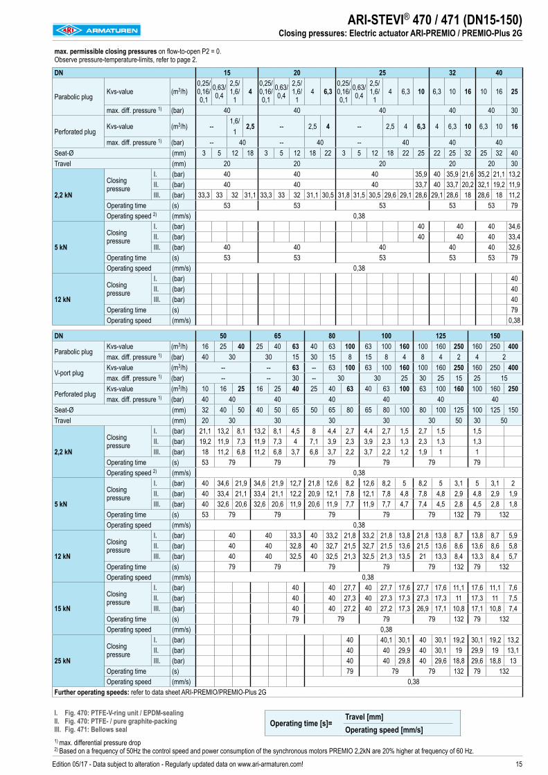
ARI-STEVI® 470 / 471 (DN15-150)Closing pressures: Electric actuator ARI-PREMIO / PREMIO-Plus 2G
max. permissible closing pressures on flow-to-open P2 = 0. Observe pressure-temperature-limits, refer to page 2.
DN 15 20 25 32 40
Parabolic plugKvs-value (m3/h)
0,25/ 0,16/ 0,1
0,63/ 0,4
2,5/ 1,6/ 1
40,25/ 0,16/ 0,1
0,63/ 0,4
2,5/ 1,6/
14 6,3
0,25/ 0,16/ 0,1
0,63/ 0,4
2,5/ 1,6/
14 6,3 10 6,3 10 16 10 16 25
max. diff. pressure 1) (bar) 40 40 40 40 40 30
Perforated plugKvs-value (m3/h) --
1,6/1
2,5 -- 2,5 4 -- 2,5 4 6,3 4 6,3 10 6,3 10 16
max. diff. pressure 1) (bar) -- 40 -- 40 -- 40 40 40Seat-Ø (mm) 3 5 12 18 3 5 12 18 22 3 5 12 18 22 25 22 25 32 25 32 40Travel (mm) 20 20 20 20 20 30
2,2 kN
Closing pressure
I. (bar) 40 40 40 35,9 40 35,9 21,6 35,2 21,1 13,2II. (bar) 40 40 40 33,7 40 33,7 20,2 32,1 19,2 11,9III. (bar) 33,3 33 32 31,1 33,3 33 32 31,1 30,5 31,8 31,5 30,5 29,6 29,1 28,6 29,1 28,6 18 28,6 18 11,2
Operating time (s) 53 53 53 53 53 79Operating speed 2) (mm/s) 0,38
5 kN
Closing pressure
I. (bar) 40 40 40 34,6II. (bar) 40 40 40 33,4III. (bar) 40 40 40 40 40 32,6
Operating time (s) 53 53 53 53 53 79Operating speed (mm/s) 0,38
12 kN
Closing pressure
I. (bar) 40II. (bar) 40III. (bar) 40
Operating time (s) 79Operating speed (mm/s) 0,38
DN 50 65 80 100 125 150
Parabolic plugKvs-value (m3/h) 16 25 40 25 40 63 40 63 100 63 100 160 100 160 250 160 250 400max. diff. pressure 1) (bar) 40 30 30 15 30 15 8 15 8 4 8 4 2 4 2
V-port plugKvs-value (m3/h) -- -- 63 -- 63 100 63 100 160 100 160 250 160 250 400max. diff. pressure 1) (bar) -- -- 30 -- 30 30 25 30 25 15 25 15
Perforated plugKvs-value (m3/h) 10 16 25 16 25 40 25 40 63 40 63 100 63 100 160 100 160 250max. diff. pressure 1) (bar) 40 40 40 40 40 40 40
Seat-Ø (mm) 32 40 50 40 50 65 50 65 80 65 80 100 80 100 125 100 125 150Travel (mm) 20 30 30 30 30 30 50 30 50
2,2 kN
Closing pressure
I. (bar) 21,1 13,2 8,1 13,2 8,1 4,5 8 4,4 2,7 4,4 2,7 1,5 2,7 1,5 1,5II. (bar) 19,2 11,9 7,3 11,9 7,3 4 7,1 3,9 2,3 3,9 2,3 1,3 2,3 1,3 1,3III. (bar) 18 11,2 6,8 11,2 6,8 3,7 6,8 3,7 2,2 3,7 2,2 1,2 1,9 1 1
Operating time (s) 53 79 79 79 79 79 79Operating speed 2) (mm/s) 0,38
5 kN
Closing pressure
I. (bar) 40 34,6 21,9 34,6 21,9 12,7 21,8 12,6 8,2 12,6 8,2 5 8,2 5 3,1 5 3,1 2II. (bar) 40 33,4 21,1 33,4 21,1 12,2 20,9 12,1 7,8 12,1 7,8 4,8 7,8 4,8 2,9 4,8 2,9 1,9III. (bar) 40 32,6 20,6 32,6 20,6 11,9 20,6 11,9 7,7 11,9 7,7 4,7 7,4 4,5 2,8 4,5 2,8 1,8
Operating time (s) 53 79 79 79 79 79 132 79 132Operating speed (mm/s) 0,38
12 kN
Closing pressure
I. (bar) 40 40 33,3 40 33,2 21,8 33,2 21,8 13,8 21,8 13,8 8,7 13,8 8,7 5,9II. (bar) 40 40 32,8 40 32,7 21,5 32,7 21,5 13,6 21,5 13,6 8,6 13,6 8,6 5,8III. (bar) 40 40 32,5 40 32,5 21,3 32,5 21,3 13,5 21 13,3 8,4 13,3 8,4 5,7
Operating time (s) 79 79 79 79 79 132 79 132Operating speed (mm/s) 0,38
15 kN
Closing pressure
I. (bar) 40 40 27,7 40 27,7 17,6 27,7 17,6 11,1 17,6 11,1 7,6II. (bar) 40 40 27,3 40 27,3 17,3 27,3 17,3 11 17,3 11 7,5III. (bar) 40 40 27,2 40 27,2 17,3 26,9 17,1 10,8 17,1 10,8 7,4
Operating time (s) 79 79 79 79 132 79 132Operating speed (mm/s) 0,38
25 kN
Closing pressure
I. (bar) 40 40,1 30,1 40 30,1 19,2 30,1 19,2 13,2II. (bar) 40 40 29,9 40 30,1 19 29,9 19 13,1III. (bar) 40 40 29,8 40 29,6 18,8 29,6 18,8 13
Operating time (s) 79 79 79 132 79 132Operating speed (mm/s) 0,38
Further operating speeds: refer to data sheet ARI-PREMIO/PREMIO-Plus 2G
I. Fig. 470: PTFE-V-ring unit / EPDM-sealing II. Fig. 470: PTFE- / pure graphite-packing III. Fig. 471: Bellows seal1) max. differential pressure drop 2) Based on a frequency of 50Hz the control speed and power consumption of the synchronous motors PREMIO 2,2kN are 20% higher at frequency of 60 Hz.
Operating time [s]=Travel [mm]Operating speed [mm/s]
16 Edition 05/17 - Data subject to alteration - Regularly updated data on www.ari-armaturen.com!
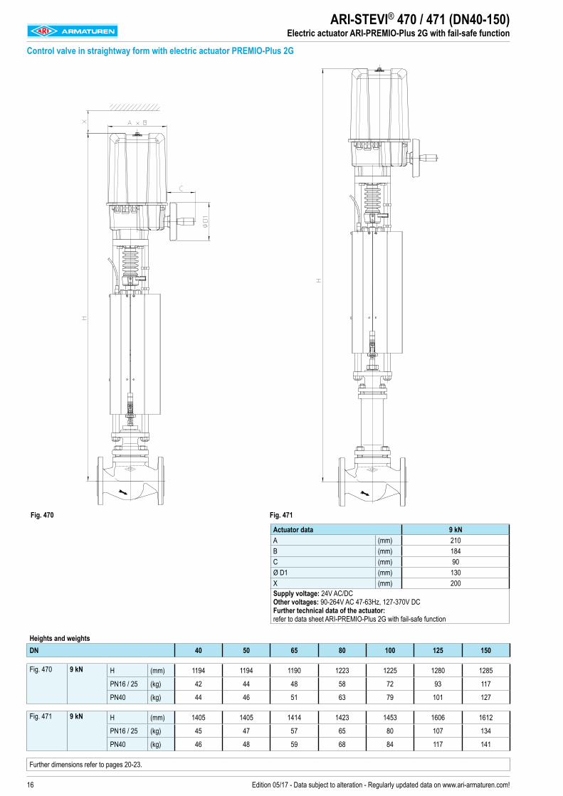
ARI-STEVI® 470 / 471 (DN40-150)Electric actuator ARI-PREMIO-Plus 2G with fail-safe function
Heights and weights DN 40 50 65 80 100 125 150
Fig. 470 9 kN H (mm) 1194 1194 1190 1223 1225 1280 1285
PN16 / 25 (kg) 42 44 48 58 72 93 117
PN40 (kg) 44 46 51 63 79 101 127
Fig. 471 9 kN H (mm) 1405 1405 1414 1423 1453 1606 1612
PN16 / 25 (kg) 45 47 57 65 80 107 134
PN40 (kg) 46 48 59 68 84 117 141
Further dimensions refer to pages 20-23.
Control valve in straightway form with electric actuator PREMIO-Plus 2G
Fig. 470 Fig. 471
Actuator data 9 kNA (mm) 210B (mm) 184C (mm) 90Ø D1 (mm) 130X (mm) 200Supply voltage: 24V AC/DC Other voltages: 90-264V AC 47-63Hz, 127-370V DC Further technical data of the actuator: refer to data sheet ARI-PREMIO-Plus 2G with fail-safe function
17Edition 05/17 - Data subject to alteration - Regularly updated data on www.ari-armaturen.com!
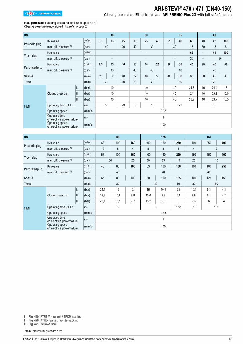
ARI-STEVI® 470 / 471 (DN40-150)Closing pressures: Electric actuator ARI-PREMIO-Plus 2G with fail-safe function
max. permissible closing pressures on flow-to-open P2 = 0. Observe pressure-temperature-limits, refer to page 2.
DN 40 50 65 80
Parabolic plugKvs-value (m3/h) 10 16 25 16 25 40 25 40 63 40 63 100
max. diff. pressure 1) (bar) 40 30 40 30 30 15 30 15 8
V-port plugKvs-value (m3/h) -- -- -- 63 -- 63 100
max. diff. pressure 1) (bar) -- -- -- 30 -- 30
Perforated plugKvs-value (m3/h) 6,3 10 16 10 16 25 16 25 40 25 40 63
max. diff. pressure 1) (bar) 40 40 40 40 40
Seat-Ø (mm) 25 32 40 32 40 50 40 50 65 50 65 80
Travel (mm) 20 30 20 30 30 30
9 kN
Closing pressure
I. (bar) 40 40 40 24,5 40 24,4 16
II. (bar) 40 40 40 24 40 23,9 15,6
III. (bar) 40 40 40 23,7 40 23,7 15,5
Operating time (50 Hz) (s) 53 79 53 79 79 79
Operating speed (mm/s) 0,38Operating time on electrical power failure (s) 1Operating speed on electrical power failure (mm/s) 100
DN 100 125 150
Parabolic plugKvs-value (m3/h) 63 100 160 100 160 250 160 250 400
max. diff. pressure 1) (bar) 15 8 4 8 4 2 4 2
V-port plugKvs-value (m3/h) 63 100 160 100 160 250 160 250 400
max. diff. pressure 1) (bar) 30 25 30 25 15 25 15
Perforated plugKvs-value (m3/h) 40 63 100 63 100 160 100 160 250
max. diff. pressure 1) (bar) 40 40 40
Seat-Ø (mm) 65 80 100 80 100 125 100 125 150
Travel (mm) 30 30 50 30 50
9 kN
Closing pressure
I. (bar) 24,4 16 10,1 16 10,1 6,3 10,1 6,3 4,3
II. (bar) 23,9 15,6 9,8 15,6 9,8 6,1 9,8 6,1 4,2
III. (bar) 23,7 15,5 9,7 15,2 9,6 6 9,6 6 4
Operating time (50 Hz) (s) 79 79 132 79 132
Operating speed (mm/s) 0,38Operating time on electrical power failure (s) 1Operating speed on electrical power failure (mm/s) 100
I. Fig. 470: PTFE-V-ring unit / EPDM-sealing II. Fig. 470: PTFE- / pure graphite-packing III. Fig. 471: Bellows seal
1) max. differential pressure drop
18 Edition 05/17 - Data subject to alteration - Regularly updated data on www.ari-armaturen.com!
Heights and weights DN 25 32 40 50 65 80 100 125 150
Fig. 470 SAR 07.2 SAR 07.6
H (mm) 652 652 683 683 679 712 714 769 774PN16 / 25 (kg) 37 39 44 45 50 60 74 95 119PN40 (kg) 38 40 45 47 53 64 80 103 129
SAR 10.2 H (mm) -- -- -- -- -- 714 716 771 776PN16 / 25 (kg) -- -- -- -- -- 62 76 97 121PN40 (kg) -- -- -- -- -- 67 83 105 131
SAR 14.2 H (mm) -- -- -- -- -- -- -- 839 869PN16 / 25 (kg) -- -- -- -- -- -- -- 140 172PN40 (kg) -- -- -- -- -- -- -- 147 182
SAR 14.6 LE100
H (mm) -- -- -- -- -- -- -- 1097 1127PN16 / 25 (kg) -- -- -- -- -- -- -- 186 218PN40 (kg) -- -- -- -- -- -- -- 193 228
Fig. 471 SAR 07.2 SAR 07.6
H (mm) 809 809 894 894 903 912 942 1095 1101PN16 / 25 (kg) 39 41 47 49 59 67 82 109 136PN40 (kg) 40 42 47 50 60 69 85 119 143
SAR 10.2 H (mm) -- -- -- -- -- 914 944 1097 1103PN16 / 25 (kg) -- -- -- -- -- 69 84 111 138PN40 (kg) -- -- -- -- -- 72 88 121 145
SAR 14.2 H (mm) -- -- -- -- -- -- -- 1398 1428PN16 / 25 (kg) -- -- -- -- -- -- -- 173 204PN40 (kg) -- -- -- -- -- -- -- 180 215
For version with AUMA SAR Ex other heights.Further dimensions refer to pages 20-23.
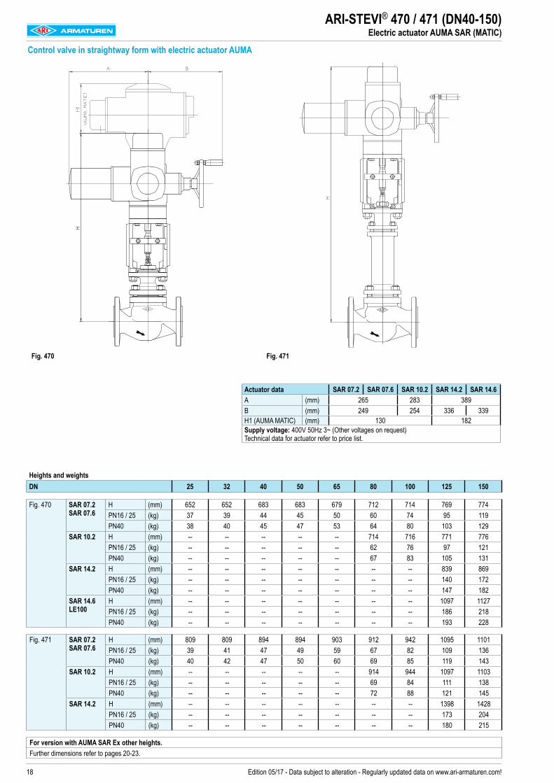
ARI-STEVI® 470 / 471 (DN40-150)Electric actuator AUMA SAR (MATIC)
Control valve in straightway form with electric actuator AUMA
Fig. 470 Fig. 471
Actuator data SAR 07.2 SAR 07.6 SAR 10.2 SAR 14.2 SAR 14.6A (mm) 265 283 389B (mm) 249 254 336 339H1 (AUMA MATIC) (mm) 130 182Supply voltage: 400V 50Hz 3~ (Other voltages on request) Technical data for actuator refer to price list.
19Edition 05/17 - Data subject to alteration - Regularly updated data on www.ari-armaturen.com!
Control valve in straightway form with electric actuator AUMA
Fig. 470 Fig. 471
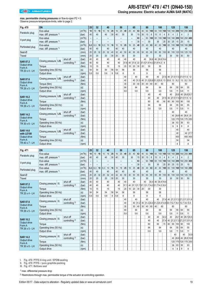
ARI-STEVI® 470 / 471 (DN40-150)Closing pressures: Electric actuator AUMA SAR (MATIC)
max. permissible closing pressures on flow-to-open P2 = 0. Observe pressure-temperature-limits, refer to page 2.
Fig. 470 DN 25 32 40 50 65 80 100 125 150
Parabolic plug Kvs-value (m3/h) 10 10 16 10 16 25 16 25 40 25 40 63 40 63 100 63 100 160 100 160 250 160 250 400max. diff. pressure 1) (bar) 40 40 40 30 40 30 30 15 30 15 8 15 8 4 8 4 2 4 2
V-port plug Kvs-value (m3/h) -- -- -- -- -- 63 -- 63 100 63 100 160 100 160 250 160 250 400max. diff. pressure 1) (bar) -- -- -- -- -- 30 -- 30 30 25 30 25 15 25 15
Perforated plug Kvs-value (m3/h) 6,3 6,3 10 6,3 10 16 10 16 25 16 25 40 25 40 63 40 63 100 63 100 160 100 160 250max. diff. pressure 1) (bar) 40 40 40 40 40 40 40 40 40 40
Seat-Ø (mm) 25 25 32 25 32 40 32 40 50 40 50 65 50 65 80 65 80 100 80 100 125 100 125 150Travel (mm) 20 20 20 30 20 30 30 30 30 30 50 30 50
SAR 07.2 Output drive Form A TR 20 x 4 - LH
Closing pressure I./II. shut off (bar) 40 40 40 40 40 40 40 30,6 40 30,6 19,4controlling 2) (bar) 40 40 40 40 37,6 40 37,6 22 37,4 21,9 14,3 21,9 14,3 9
Torque (Nm) 15 15 15 15 20 15 20 30 20 30 30Operating time (50 Hz) (s) 54 54 54 56 54 56 56 56 56Output drive (rpm) 5,6 5,6 5,6 8 5,6 8 8 8 8
SAR 07.6 Output drive Form A TR 26 x 5 - LH
Closing pressure I./II. shut off (bar) 40 40 40 40 27,5 40 27,5 17,5 27,5 17,5 12controlling 2) (bar) 40 40 31,5 40 31,3 20,6 31,3 20,6 13 20,6 13 8,2 13 8,2 5,6
Torque (Nm) (Nm) 30 30 40 30 40 60 40 60 60 60Operating time (50 Hz) (s) 64 64 64 64 64 55 64 55Output drive (rpm) 5,6 5,6 5,6 5,6 5,6 11 5,6 11
SAR 10.2 Output drive Form A TR 26 x 5 - LH
Closing pressure I./II. shut off (bar) 40 40 40 29,8 40 29,8 20,7controlling 2) (bar) 40 40 27,5 40 27,5 17,5 27,5 17,5 12
Torque (Nm) 60 60 90 60 90 100 90 100Operating time (50 Hz) (s) 64 64 64 55 64 55Output drive (rpm) 5,6 5,6 5,6 11 5,6 11
SAR 14.2 Output drive Form A TR 30 x 6 - LH
Closing pressure I./II. shut off (bar) 40 40controlling 2) (bar) 40 28,9 40 28,9 20
Torque (Nm) 120 175 120 175 250Operating time (50 Hz) (s) 38 63 38 63Output drive (rpm) 8 8 8 8
SAR 14.6 with LE100 Output drive Form A TR 40 x 7 - LH
Closing pressure I./II. shut off (bar) 40 40controlling 2) (bar) 40 40 27,7
Torque (Nm) 400 400 400Operating time (50 Hz) (s) 54 54Output drive (rpm) 8 8
Fig. 471 DN 25 32 40 50 65 80 100 125 150
Parabolic plug Kvs-value (m3/h) 10 10 16 10 16 25 16 25 40 25 40 63 40 63 100 63 100 160 100 160 250 160 250 400max. diff. pressure 1) (bar) 40 40 40 30 40 30 30 15 30 15 8 15 8 4 8 4 2 4 2
V-port plug Kvs-value (m3/h) -- -- -- -- -- 63 -- 63 100 63 100 160 100 160 250 160 250 400max. diff. pressure 1) (bar) -- -- -- -- -- 30 -- 30 30 25 30 25 15 25 15
Perforated plug Kvs-value (m3/h) 6,3 6,3 10 6,3 10 16 10 16 25 16 25 40 25 40 63 40 63 100 63 100 160 100 160 250max. diff. pressure 1) (bar) 40 40 40 40 40 40 40 40 40 40
Seat-Ø (mm) 25 25 32 25 32 40 32 40 50 40 50 65 50 65 80 65 80 100 80 100 125 100 125 150Travel (mm) 20 20 20 30 20 30 30 30 30 30 50 30 50
SAR 07.2 Output drive Form A TR 20 x 4 - LH
Closing pressure III. shut off (bar) 40 40 40 40 40 40 40 30,4 40 30,4 19,4controlling 2) (bar) 40 40 40 40 37,1 40 37,1 21,7 37,1 21,7 14,2 21,7 14,2 8,9
Torque (Nm) 15 15 15 15 20 15 20 30 20 30 30Operating time (50 Hz) (s) 54 54 54 56 54 56 56 56 56Output drive (rpm) 5,6 5,6 5,6 8 5,6 8 8 8 8
SAR 07.6 Output drive Form A TR 26 x 5 - LH
Closing pressure III. shut off (bar) 40 40 40 40 27,4 40 27,2 17,3 27,2 17,3 11,9controlling 2) (bar) 40 40 31,2 40 31,2 20,4 31,2 20,4 12,9 20,1 12,7 8,0 12,7 8,0 5,5
Torque (Nm) 30 30 40 30 40 60 40 60 60 60Operating time (50 Hz) (s) 64 64 64 64 64 55 64 55Output drive (rpm) 5,6 5,6 5,6 5,6 5,6 11 5,6 11
SAR 10.2 Output drive Form A TR 26 x 5 - LH
Closing pressure III. shut off (bar) 40 40 32,2 40 29,7 40 29,7 20,5controlling 2) (bar) 40 40 27,4 40 27,2 17,3 27,2 17,3 11,9
Torque (Nm) 60 60 70 60 90 100 90 100Operating time (50 Hz) (s) 64 64 64 55 64 55Output drive (rpm) 5,6 5,6 5,6 11 5,6 11
SAR 14.2 Output drive Form A TR 30 x 6 - LH
Closing pressure III. shut off (bar) 40 40 33,9controlling 2) (bar) 40 28,8 40 28,8 19,9
Torque (Nm) 120 175 120 175 200Operating time (50 Hz) (s) 38 63 38 63Output drive (rpm) 8 8 8 8
I. Fig. 470: PTFE-V-ring unit / EPDM-sealing II. Fig. 470: PTFE- / pure graphite-packing III. Fig. 471: Bellows seal1) max. differential pressure drop 2) Restrictions through max. permissible torque of the actuator at controlling operation.
20 Edition 05/17 - Data subject to alteration - Regularly updated data on www.ari-armaturen.com!
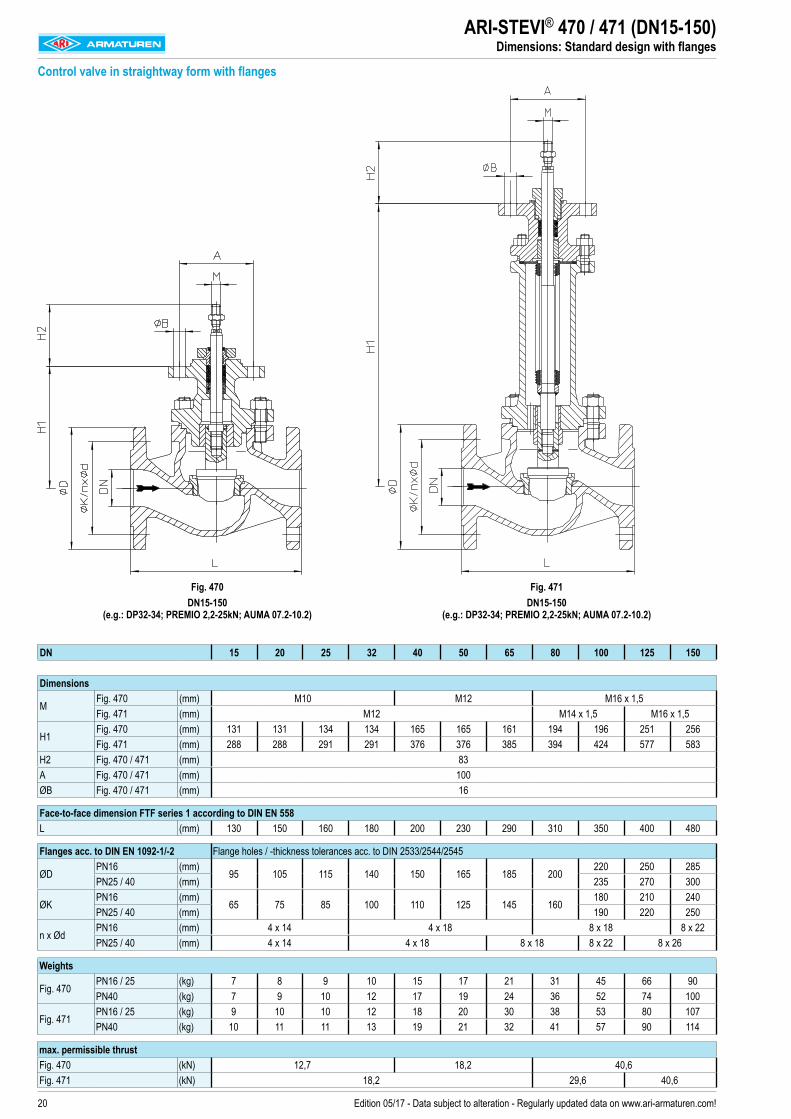
ARI-STEVI® 470 / 471 (DN15-150)Dimensions: Standard design with flanges
Control valve in straightway form with flanges
Fig. 470 DN15-150
(e.g.: DP32-34; PREMIO 2,2-25kN; AUMA 07.2-10.2)
Fig. 471 DN15-150
(e.g.: DP32-34; PREMIO 2,2-25kN; AUMA 07.2-10.2)
DN 15 20 25 32 40 50 65 80 100 125 150
Dimensions
MFig. 470 (mm) M10 M12 M16 x 1,5Fig. 471 (mm) M12 M14 x 1,5 M16 x 1,5
H1Fig. 470 (mm) 131 131 134 134 165 165 161 194 196 251 256Fig. 471 (mm) 288 288 291 291 376 376 385 394 424 577 583
H2 Fig. 470 / 471 (mm) 83A Fig. 470 / 471 (mm) 100ØB Fig. 470 / 471 (mm) 16
Face-to-face dimension FTF series 1 according to DIN EN 558L (mm) 130 150 160 180 200 230 290 310 350 400 480
Flanges acc. to DIN EN 1092-1/-2 Flange holes / -thickness tolerances acc. to DIN 2533/2544/2545
ØDPN16 (mm)
95 105 115 140 150 165 185 200220 250 285
PN25 / 40 (mm) 235 270 300
ØKPN16 (mm)
65 75 85 100 110 125 145 160180 210 240
PN25 / 40 (mm) 190 220 250
n x ØdPN16 (mm) 4 x 14 4 x 18 8 x 18 8 x 22PN25 / 40 (mm) 4 x 14 4 x 18 8 x 18 8 x 22 8 x 26
Weights
Fig. 470PN16 / 25 (kg) 7 8 9 10 15 17 21 31 45 66 90PN40 (kg) 7 9 10 12 17 19 24 36 52 74 100
Fig. 471PN16 / 25 (kg) 9 10 10 12 18 20 30 38 53 80 107PN40 (kg) 10 11 11 13 19 21 32 41 57 90 114
max. permissible thrustFig. 470 (kN) 12,7 18,2 40,6Fig. 471 (kN) 18,2 29,6 40,6
21Edition 05/17 - Data subject to alteration - Regularly updated data on www.ari-armaturen.com!
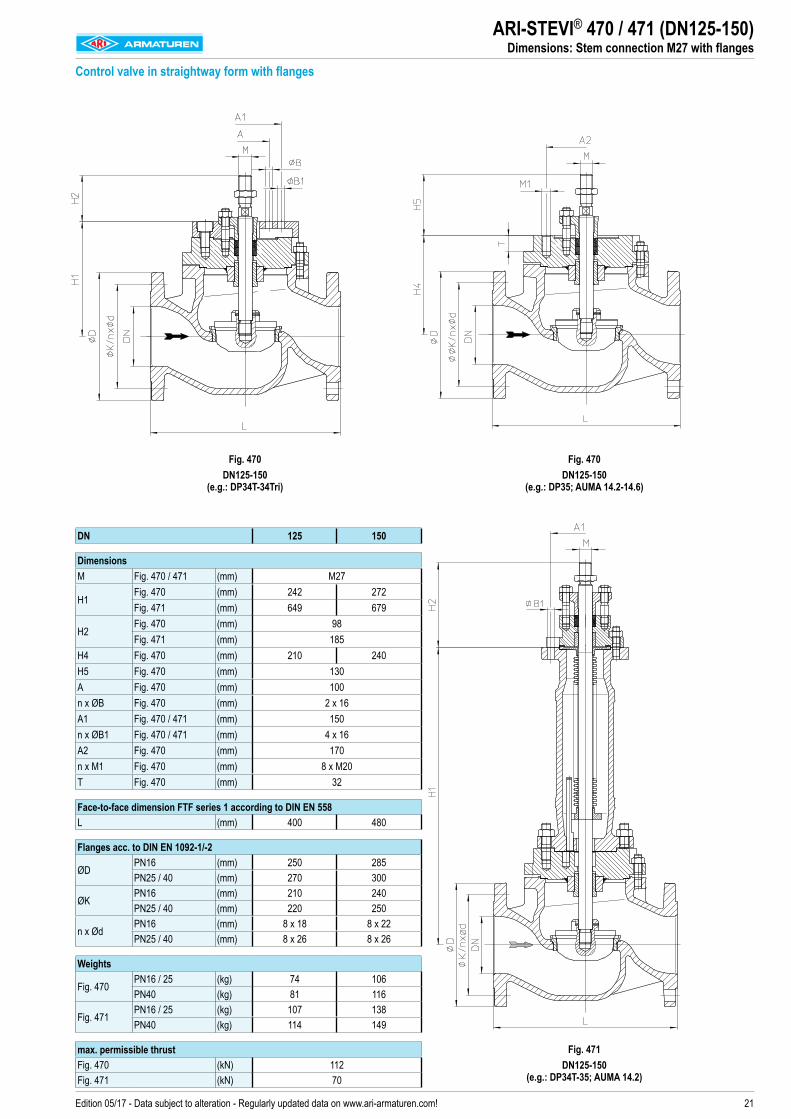
ARI-STEVI® 470 / 471 (DN125-150)Dimensions: Stem connection M27 with flanges
Control valve in straightway form with flanges
Fig. 470DN125-150
(e.g.: DP34T-34Tri)
Fig. 470 DN125-150
(e.g.: DP35; AUMA 14.2-14.6)
Fig. 471
DN125-150 (e.g.: DP34T-35; AUMA 14.2)
DN 125 150
DimensionsM Fig. 470 / 471 (mm) M27
H1Fig. 470 (mm) 242 272Fig. 471 (mm) 649 679
H2Fig. 470 (mm) 98Fig. 471 (mm) 185
H4 Fig. 470 (mm) 210 240H5 Fig. 470 (mm) 130A Fig. 470 (mm) 100n x ØB Fig. 470 (mm) 2 x 16A1 Fig. 470 / 471 (mm) 150n x ØB1 Fig. 470 / 471 (mm) 4 x 16A2 Fig. 470 (mm) 170n x M1 Fig. 470 (mm) 8 x M20T Fig. 470 (mm) 32
Face-to-face dimension FTF series 1 according to DIN EN 558L (mm) 400 480
Flanges acc. to DIN EN 1092-1/-2
ØDPN16 (mm) 250 285PN25 / 40 (mm) 270 300
ØKPN16 (mm) 210 240PN25 / 40 (mm) 220 250
n x ØdPN16 (mm) 8 x 18 8 x 22PN25 / 40 (mm) 8 x 26 8 x 26
Weights
Fig. 470PN16 / 25 (kg) 74 106PN40 (kg) 81 116
Fig. 471PN16 / 25 (kg) 107 138PN40 (kg) 114 149
max. permissible thrustFig. 470 (kN) 112Fig. 471 (kN) 70
22 Edition 05/17 - Data subject to alteration - Regularly updated data on www.ari-armaturen.com!
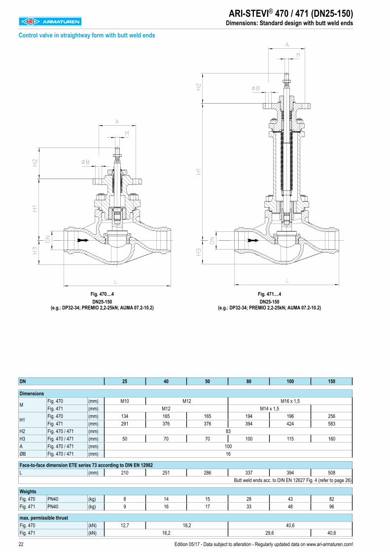
ARI-STEVI® 470 / 471 (DN25-150)Dimensions: Standard design with butt weld ends
Control valve in straightway form with butt weld ends
Fig. 470....4 DN25-150
(e.g.: DP32-34; PREMIO 2,2-25kN; AUMA 07.2-10.2)
Fig. 471....4 DN25-150
(e.g.: DP32-34; PREMIO 2,2-25kN; AUMA 07.2-10.2)
DN 25 40 50 80 100 150
Dimensions
MFig. 470 (mm) M10 M12 M16 x 1,5Fig. 471 (mm) M12 M14 x 1,5
H1Fig. 470 (mm) 134 165 165 194 196 256Fig. 471 (mm) 291 376 376 394 424 583
H2 Fig. 470 / 471 (mm) 83H3 Fig. 470 / 471 (mm) 50 70 70 100 115 160A Fig. 470 / 471 (mm) 100ØB Fig. 470 / 471 (mm) 16
Face-to-face dimension ETE series 73 according to DIN EN 12982L (mm) 210 251 286 337 394 508 Butt weld ends acc. to DIN EN 12627 Fig. 4 (refer to page 26)
WeightsFig. 470 PN40 (kg) 8 14 15 28 43 82Fig. 471 PN40 (kg) 9 16 17 33 48 96
max. permissible thrustFig. 470 (kN) 12,7 18,2 40,6Fig. 471 (kN) 18,2 29,6 40,6
23Edition 05/17 - Data subject to alteration - Regularly updated data on www.ari-armaturen.com!
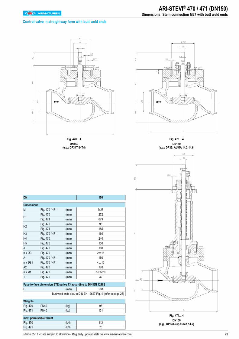
ARI-STEVI® 470 / 471 (DN150)Dimensions: Stem connection M27 with butt weld ends
Control valve in straightway form with butt weld ends
Fig. 470....4DN150
(e.g.: DP34T-34Tri)
Fig. 470....4 DN150
(e.g.: DP35; AUMA 14.2-14.6)
Fig. 471....4
DN150 (e.g.: DP34T-35; AUMA 14.2)
DN 150
DimensionsM Fig. 470 / 471 (mm) M27
H1Fig. 470 (mm) 272Fig. 471 (mm) 679
H2Fig. 470 (mm) 98Fig. 471 (mm) 185
H3 Fig. 470 / 471 (mm) 160H4 Fig. 470 (mm) 240H5 Fig. 470 (mm) 130A Fig. 470 (mm) 100n x ØB Fig. 470 (mm) 2 x 16A1 Fig. 470 / 471 (mm) 150n x ØB1 Fig. 470 / 471 (mm) 4 x 16A2 Fig. 470 (mm) 170n x M1 Fig. 470 (mm) 8 x M20T Fig. 470 (mm) 32
Face-to-face dimension ETE series 73 according to DIN EN 12982L (mm) 508 Butt weld ends acc. to DIN EN 12627 Fig. 4 (refer to page 26)
WeightsFig. 470 PN40 (kg) 98Fig. 471 PN40 (kg) 131
max. permissible thrustFig. 470 (kN) 112Fig. 471 (kN) 70
24 Edition 05/17 - Data subject to alteration - Regularly updated data on www.ari-armaturen.com!
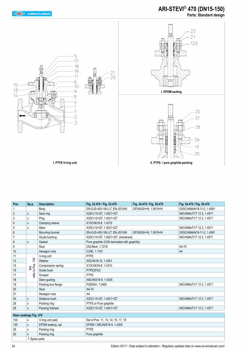
ARI-STEVI® 470 (DN15-150)Parts: Standard design
I. PTFE-V-ring unit
I. EPDM-sealing
II. PTFE- / pure graphite-packing
Pos. Sp.p. Description Fig. 22.470 / Fig. 23.470 Fig. 34.470 / Fig. 35.470 Fig. 54.470 / Fig. 55.4701 Body EN-GJS-400-18U-LT, EN-JS1049 GP240GH+N, 1.0619+N GX5CrNiMoN19-11-2, 1.45812 x Seat ring X20Cr13+QT, 1.4021+QT X6CrNiMoTi17 12 2, 1.45713 x Plug X20Cr13+QT, 1.4021+QT X6CrNiMoTi17 12 2, 1.45714 x Clamping sleeve X10CrNi18-8, 1.43105 x Stem X20Cr13+QT, 1.4021+QT X6CrNiMoTi17 12 2, 1.45716 Mounting bonnet EN-GJS-400-18U-LT, EN-JS1049 GP240GH+N, 1.0619+N GX5CrNiMoN19-11-2, 1.45817 Giude bushing X20Cr13+QT, 1.4021+QT (hardened) X6CrNiMoTi17 12 2, 1.45718 x Gasket Pure graphite (CrNi laminated with graphite)9 Stud 25CrMo4, 1.7218 A4-7010 Hexagon nuts C35E, 1.1181 A411
Set:
refer
to P
os. 1
00
V-ring unit PTFE13 Washer X5CrNi18-10, 1.430114 Compression spring X10CrNi18-8, 1.431015 Guide bush PTFE25%C17 Scraper PTFE18 Stem guiding X8CrNiS18-9, 1.430519 Packing box flange P250GH, 1.0460 X6CrNiMoTi17 12 2, 1.457120 Stud A4-7021 Hexagon nuts A425 x Distance bush X20Cr13+QT, 1.4021+QT X6CrNiMoTi17 12 2, 1.457126 x Packing ring PTFE or Pure graphite28 x Packing follower X20Cr13+QT, 1.4021+QT X6CrNiMoTi17 12 2, 1.4571
Stem sealings Fig. 470100 x V-ring unit (set) Set of Pos. 11, 13, 14, 15, 17, 18120 x EPDM-sealing, cpl. EPDM / X8CrNiS18-9, 1.430526 x Packing ring PTFE26 x Packing ring Pure graphite
└ Spare parts
25Edition 05/17 - Data subject to alteration - Regularly updated data on www.ari-armaturen.com!
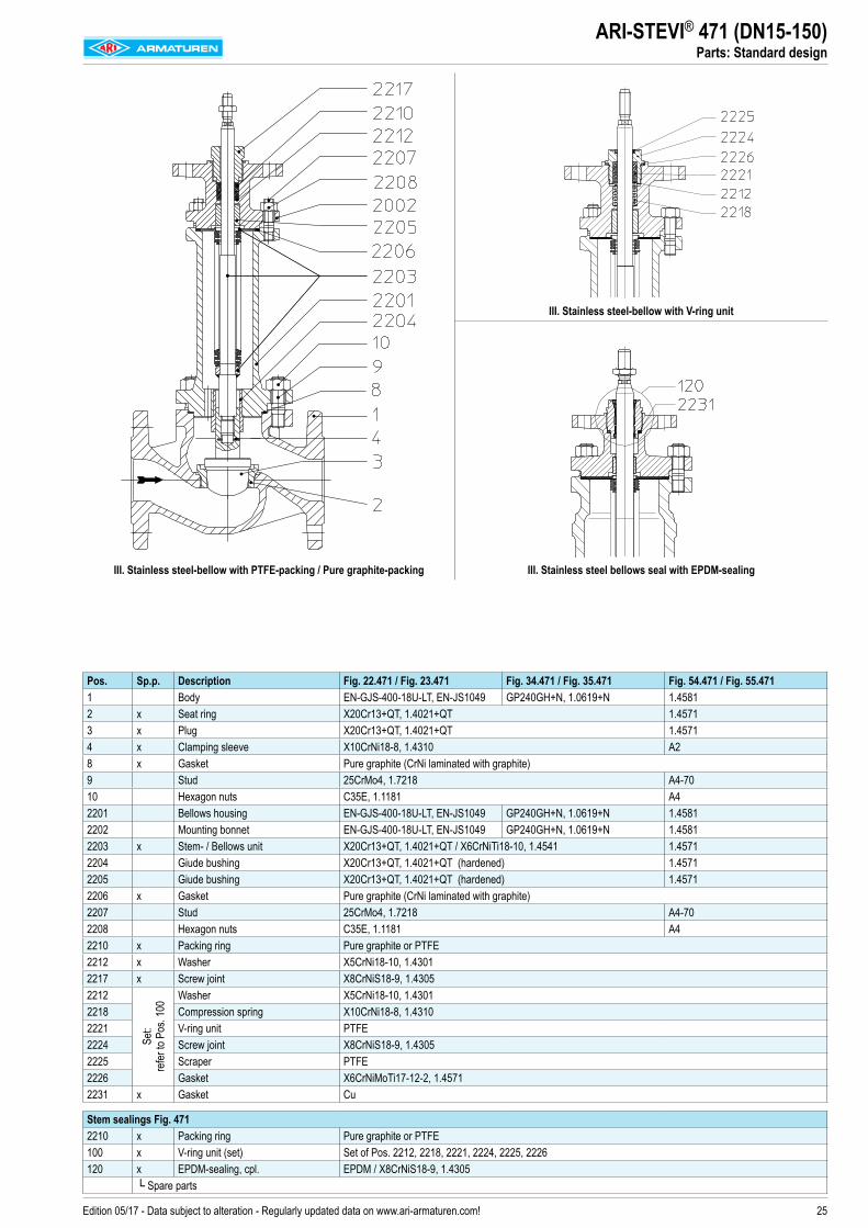
ARI-STEVI® 471 (DN15-150)Parts: Standard design
Pos. Sp.p. Description Fig. 22.471 / Fig. 23.471 Fig. 34.471 / Fig. 35.471 Fig. 54.471 / Fig. 55.4711 Body EN-GJS-400-18U-LT, EN-JS1049 GP240GH+N, 1.0619+N 1.45812 x Seat ring X20Cr13+QT, 1.4021+QT 1.45713 x Plug X20Cr13+QT, 1.4021+QT 1.45714 x Clamping sleeve X10CrNi18-8, 1.4310 A28 x Gasket Pure graphite (CrNi laminated with graphite)9 Stud 25CrMo4, 1.7218 A4-7010 Hexagon nuts C35E, 1.1181 A42201 Bellows housing EN-GJS-400-18U-LT, EN-JS1049 GP240GH+N, 1.0619+N 1.45812202 Mounting bonnet EN-GJS-400-18U-LT, EN-JS1049 GP240GH+N, 1.0619+N 1.45812203 x Stem- / Bellows unit X20Cr13+QT, 1.4021+QT / X6CrNiTi18-10, 1.4541 1.45712204 Giude bushing X20Cr13+QT, 1.4021+QT (hardened) 1.45712205 Giude bushing X20Cr13+QT, 1.4021+QT (hardened) 1.45712206 x Gasket Pure graphite (CrNi laminated with graphite)2207 Stud 25CrMo4, 1.7218 A4-702208 Hexagon nuts C35E, 1.1181 A42210 x Packing ring Pure graphite or PTFE2212 x Washer X5CrNi18-10, 1.43012217 x Screw joint X8CrNiS18-9, 1.43052212
Set:
refer
to P
os. 1
00
Washer X5CrNi18-10, 1.43012218 Compression spring X10CrNi18-8, 1.43102221 V-ring unit PTFE2224 Screw joint X8CrNiS18-9, 1.43052225 Scraper PTFE2226 Gasket X6CrNiMoTi17-12-2, 1.45712231 x Gasket Cu
Stem sealings Fig. 4712210 x Packing ring Pure graphite or PTFE100 x V-ring unit (set) Set of Pos. 2212, 2218, 2221, 2224, 2225, 2226120 x EPDM-sealing, cpl. EPDM / X8CrNiS18-9, 1.4305
└ Spare parts
III. Stainless steel-bellow with PTFE-packing / Pure graphite-packing
III. Stainless steel-bellow with V-ring unit
III. Stainless steel bellows seal with EPDM-sealing
26 Edition 05/17 - Data subject to alteration - Regularly updated data on www.ari-armaturen.com!
ARI-STEVI® 470 / 471 (DN25-150)Valves with butt weld ends
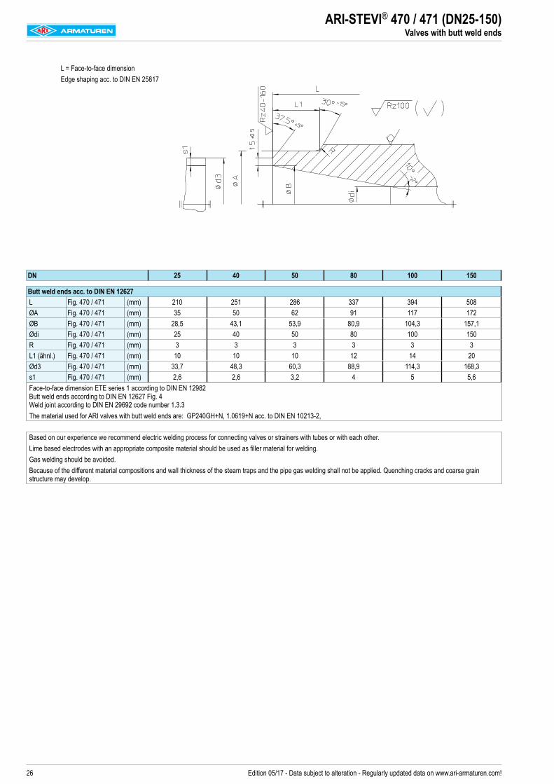
L = Face-to-face dimensionEdge shaping acc. to DIN EN 25817
DN 25 40 50 80 100 150
Butt weld ends acc. to DIN EN 12627L Fig. 470 / 471 (mm) 210 251 286 337 394 508ØA Fig. 470 / 471 (mm) 35 50 62 91 117 172ØB Fig. 470 / 471 (mm) 28,5 43,1 53,9 80,9 104,3 157,1Ødi Fig. 470 / 471 (mm) 25 40 50 80 100 150R Fig. 470 / 471 (mm) 3 3 3 3 3 3L1 (ähnl.) Fig. 470 / 471 (mm) 10 10 10 12 14 20Ød3 Fig. 470 / 471 (mm) 33,7 48,3 60,3 88,9 114,3 168,3s1 Fig. 470 / 471 (mm) 2,6 2,6 3,2 4 5 5,6Face-to-face dimension ETE series 1 according to DIN EN 12982 Butt weld ends according to DIN EN 12627 Fig. 4 Weld joint according to DIN EN 29692 code number 1.3.3 The material used for ARI valves with butt weld ends are: GP240GH+N, 1.0619+N acc. to DIN EN 10213-2,
Based on our experience we recommend electric welding process for connecting valves or strainers with tubes or with each other. Lime based electrodes with an appropriate composite material should be used as filler material for welding.Gas welding should be avoided.Because of the different material compositions and wall thickness of the steam traps and the pipe gas welding shall not be applied. Quenching cracks and coarse grain structure may develop.

27Edition 05/17 - Data subject to alteration - Regularly updated data on www.ari-armaturen.com!
ARI-STEVI® 470 / 471 Notes
28 Edition 05/17 - Data subject to alteration - Regularly updated data on www.ari-armaturen.com!
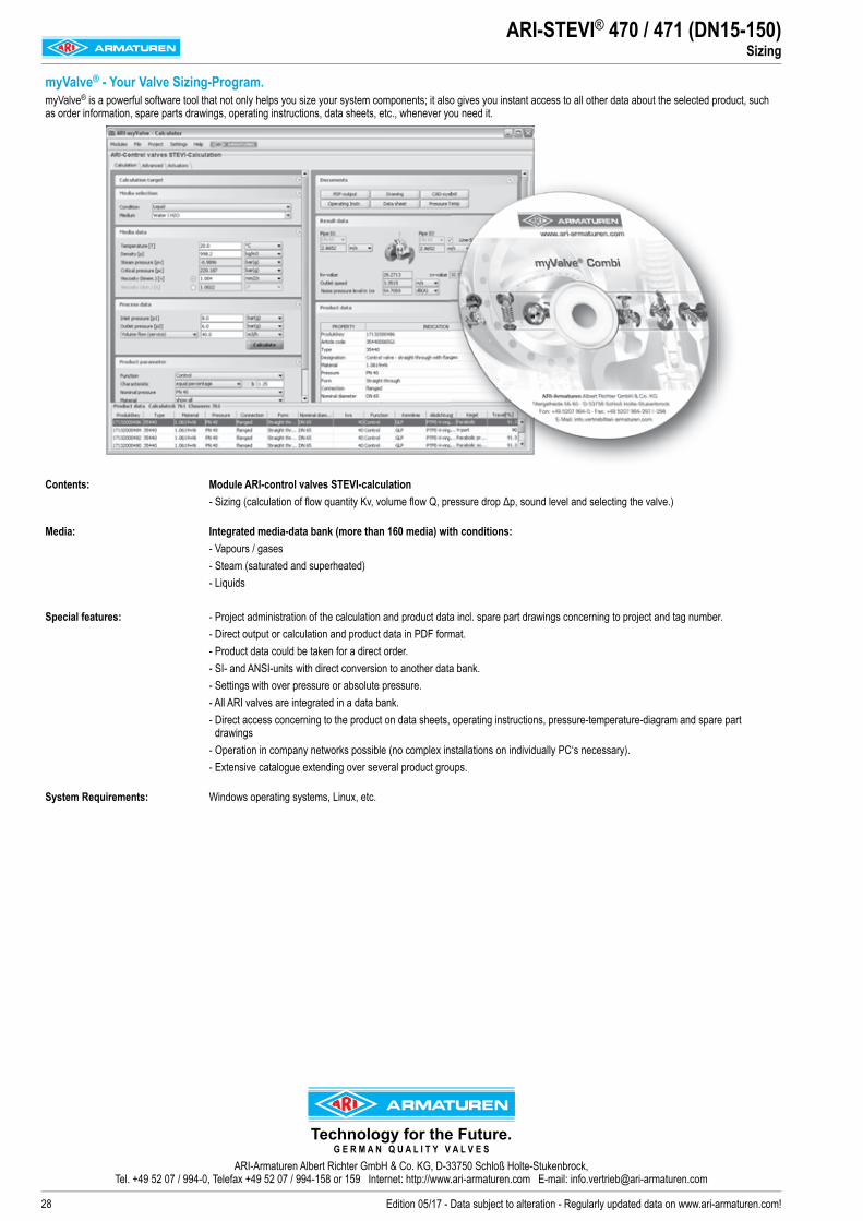
ARI-STEVI® 470 / 471 (DN15-150)Sizing
myValve® - Your Valve Sizing-Program.myValve® is a powerful software tool that not only helps you size your system components; it also gives you instant access to all other data about the selected product, such as order information, spare parts drawings, operating instructions, data sheets, etc., whenever you need it.
Contents: Module ARI-control valves STEVI-calculation- Sizing (calculation of flow quantity Kv, volume flow Q, pressure drop Δp, sound level and selecting the valve.)
Media: Integrated media-data bank (more than 160 media) with conditions:- Vapours / gases- Steam (saturated and superheated)- Liquids
Special features: - Project administration of the calculation and product data incl. spare part drawings concerning to project and tag number.- Direct output or calculation and product data in PDF format.- Product data could be taken for a direct order.- SI- and ANSI-units with direct conversion to another data bank.- Settings with over pressure or absolute pressure.- All ARI valves are integrated in a data bank.- Direct access concerning to the product on data sheets, operating instructions, pressure-temperature-diagram and spare part
drawings - Operation in company networks possible (no complex installations on individually PC‘s necessary).- Extensive catalogue extending over several product groups.
System Requirements: Windows operating systems, Linux, etc.
Technology for the Future.G E R M A N Q U A L I T Y V A L V E S
ARI-Armaturen Albert Richter GmbH & Co. KG, D-33750 Schloß Holte-Stukenbrock, Tel. +49 52 07 / 994-0, Telefax +49 52 07 / 994-158 or 159 Internet: http://www.ari-armaturen.com E-mail: [email protected]