arc flash mitigation – an overview - western mining ...wmea.net/technical...
TRANSCRIPT
Gus Nasrallah, P.E.
Electroswitch
May 30, 2013
Arc Flash Mitigation – An Overview
Agenda Origin of Modern Arc Flash studies
Why Now more than before
NFPA 70E Standards
Protection Zone
IEEE 1584 – 2002
IEEE 1584 Vs NFPA 70E
Arc Flash Assessment & Mitigation
Minimizing Energy
Unit Presence of Personnel Near Arc Flash
Options Available Arc Flash Resistant switchgear, Chicken switch, Time delay
switches and Relays
Questions
What is Arc Flash?
“An Arc Flash is an electric current that passes through air when insulation or isolation between electrical conductors is no longer sufficient to withstand the applied voltage.” [NFPA 70E]
“Arc flash results from an arcing fault, where the electric arcs and resulting radiation and shrapnel cause severe skin burns, hearing damage, and eye injuries. “(OSHA Training Grant SH-16614-07)
Arc flash causes damage from energy flux, not electric current and is distinct from electrocution.
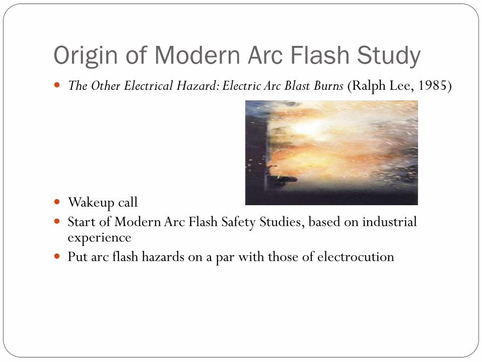
Origin of Modern Arc Flash Study The Other Electrical Hazard: Electric Arc Blast Burns (Ralph Lee, 1985)
Wakeup call
Start of Modern Arc Flash Safety Studies, based on industrial experience
Put arc flash hazards on a par with those of electrocution
Origin of Modern Arc Flash Study
Key Results from Lee 1985:
Arcs are extremely hot: 4 x Temperature of the Sun
Importance of incident energy and threshold for very serious burns of
1.2 cal/cm2 - still in use.
Calculation of effects of arc current, distance from arc, voltage, and
other variables. More on this later.
“All that is necessary to incur serious or fatal injuries is to be within five
feet or so from a severe power arc with bare skin or flammable clothing.”
Other Key Early Work Pressures Developed by Arcs, Ralph Lee 1987.
Up to 2,000 psf
Testing Update on Protective Clothing and Equipment for Electric Arc Exposure, Bingham, Doughty, and Neal 1997 Besides data on personnel protective equipment and clothing (PPE) also discussed the amplifying effect of enclosures.
Predicting Incident Energy to Better Manage the Electric Arc Hazard on 600-V Power Distribution Systems, Doughty, Floyd, and Neal 2000
Why now?
More attention to worker safety
More medium and high voltage feeds in industrial
applications
Better data (and more is on the way)
Large increase in electricity usage
Higher Efficiency Equipment (Lower Impedance)
NFPA 70E
Provides guidelines to limit injuries to second degree burns.
Defines zones depending on risks of electrocution and arc
flash burns.
NFPA 70E
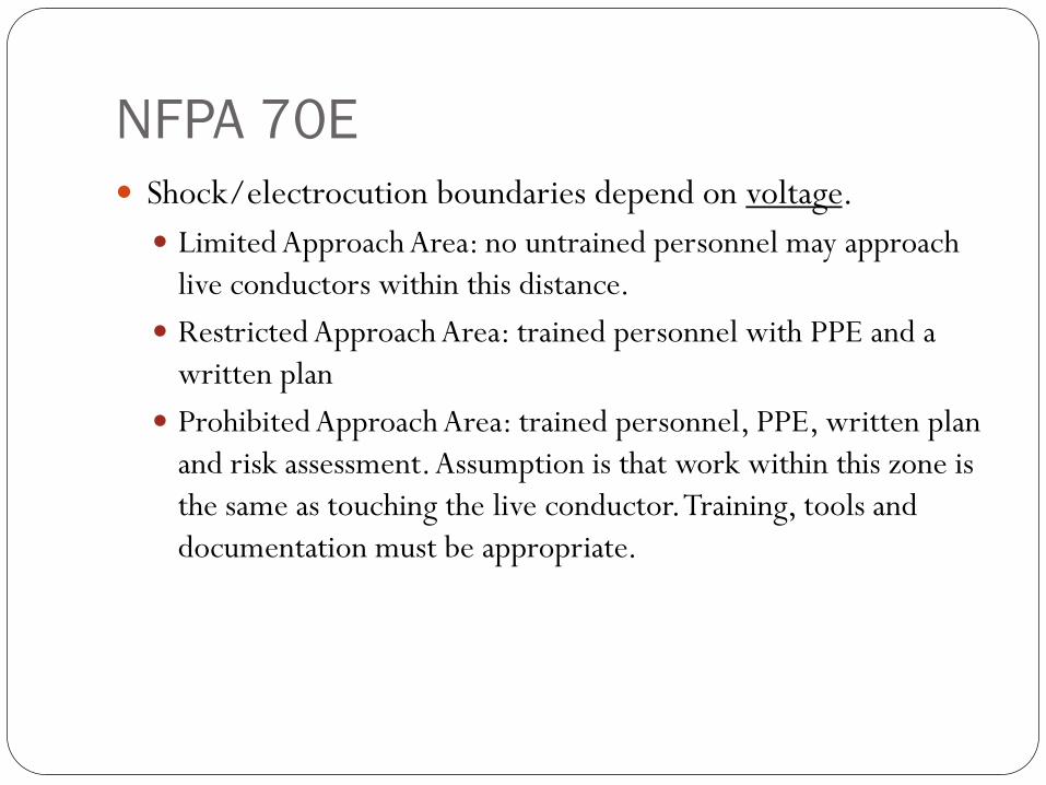
Shock/electrocution boundaries depend on voltage.
Limited Approach Area: no untrained personnel may approach
live conductors within this distance.
Restricted Approach Area: trained personnel with PPE and a
written plan
Prohibited Approach Area: trained personnel, PPE, written plan
and risk assessment. Assumption is that work within this zone is
the same as touching the live conductor. Training, tools and
documentation must be appropriate.
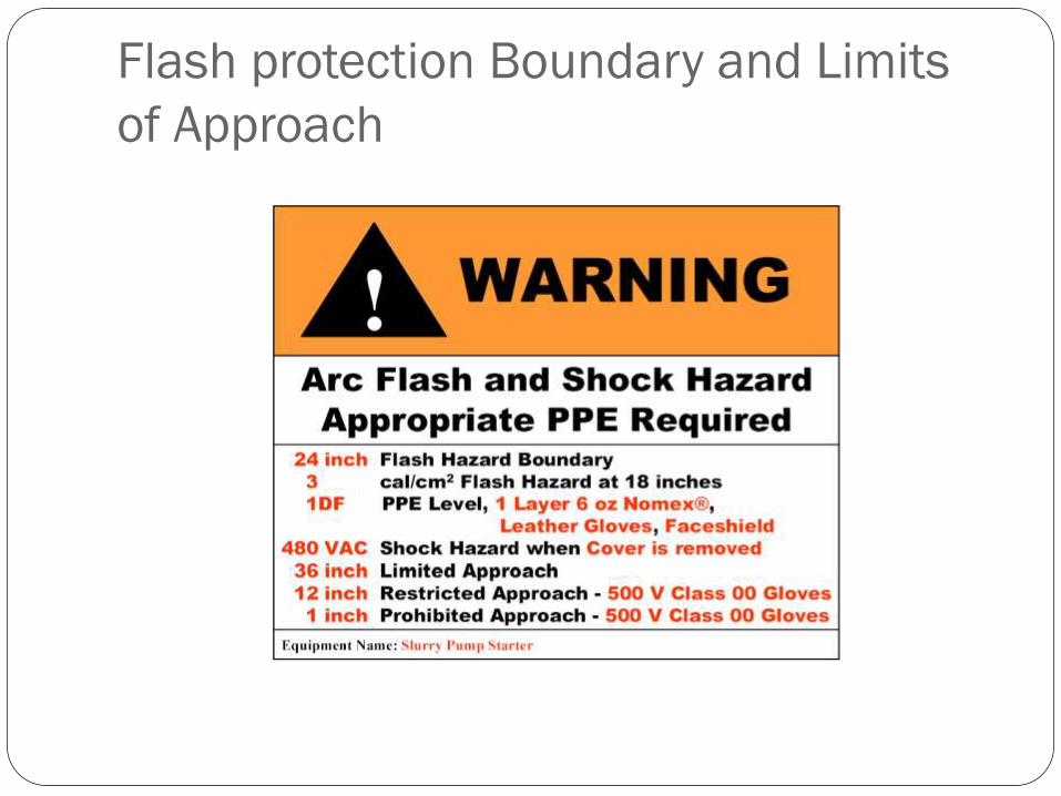
Flash protection Boundary and Limits
of Approach
NFPA 70E NFPA 70E, Section 130.3 (B) states:
The incident energy exposure level shall be based on the working
distance of the worker’s face and chest areas from a prospective
arc source for the specific task to be performed
NFPA 70E
Flash Protection Boundary
Depends on available energy: arc voltage * fault current *
duration
Can easily be a larger or smaller area than the limits from
system voltage
NFPA calculations are easy to do and are often conservative.
There are three methods in NFPA 70E, with different
applicability and computational effort required.
Online calculators and other tools are available.
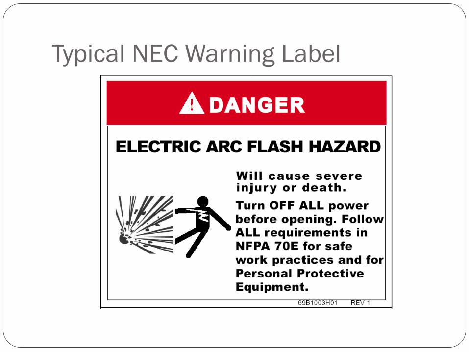
Typical NEC Warning Label
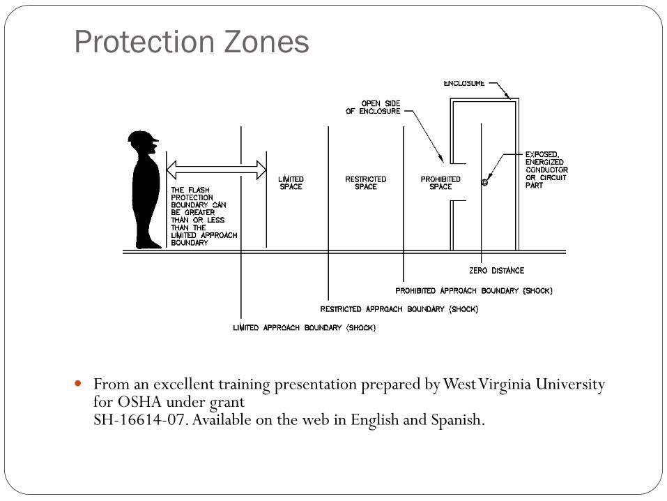
Protection Zones
From an excellent training presentation prepared by West Virginia University for OSHA under grant SH-16614-07. Available on the web in English and Spanish.
NFPA 70E Boundries
Good safety practices minimize risk:
Switch remotely if possible.
Standing aside and away as much as possible during
switching.
Avoid leaning on or touching switchgear and
metallic surfaces.
Use proper tools and PPE.
IEEE 1584-2002
Guide for Performing Arc Flash Hazard Calculations
Based on statistical analysis of lab data
Well defined, but somewhat lengthy procedure for
calculating energy, flash boundary and required PPE.
49 case studies of incidents
IEEE 1584
In the process of being revised, hopefully for this year.
Extensive, well funded effort to get new data
Should cover a variety of situations (new voltages) with new
experimental data
More accurate equations
Using IEEE 1584 to Calculate Incident
Energy and Flash Boundary
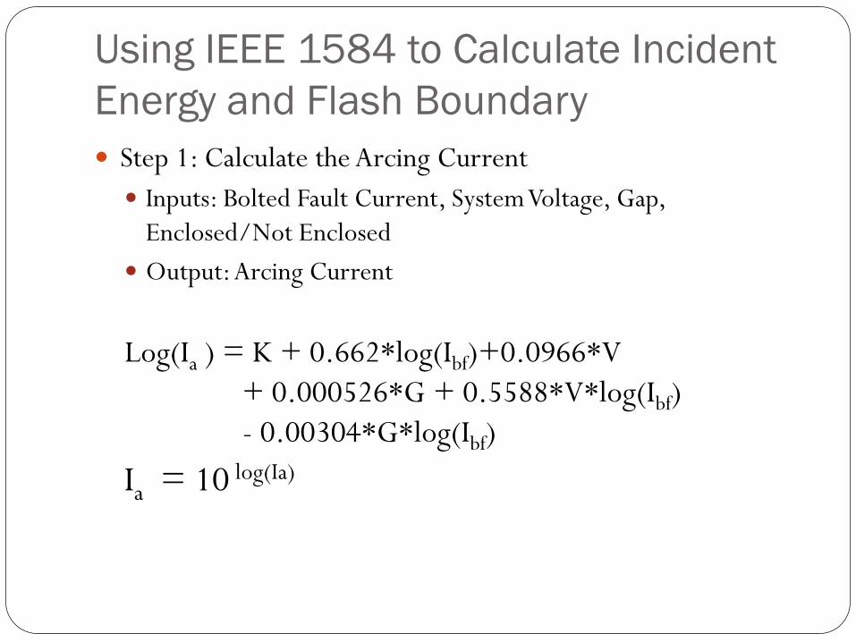
Step 1: Calculate the Arcing Current
Inputs: Bolted Fault Current, System Voltage, Gap,
Enclosed/Not Enclosed
Output: Arcing Current
Log(Ia ) = K + 0.662*log(Ibf)+0.0966*V
+ 0.000526*G + 0.5588*V*log(Ibf)
- 0.00304*G*log(Ibf)
Ia = 10 log(Ia)
Using IEEE 1584 to Calculate Incident
Energy and Flash Boundary
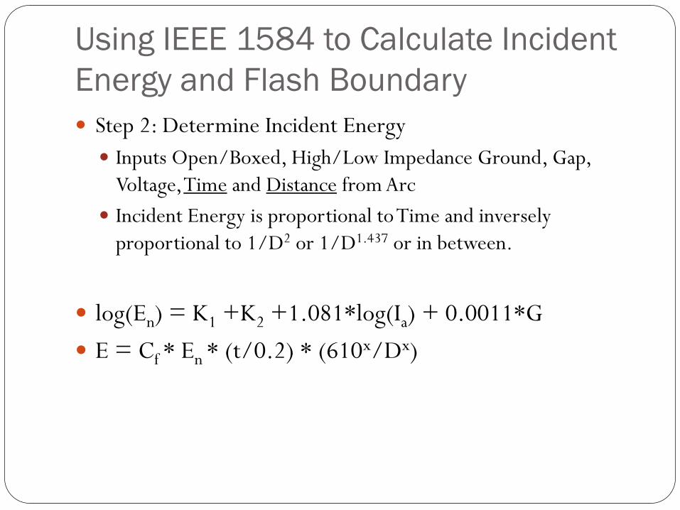
Step 2: Determine Incident Energy
Inputs Open/Boxed, High/Low Impedance Ground, Gap,
Voltage, Time and Distance from Arc
Incident Energy is proportional to Time and inversely
proportional to 1/D2 or 1/D1.437 or in between.
log(En) = K1 +K2 +1.081*log(Ia) + 0.0011*G
E = Cf * En * (t/0.2) * (610x/Dx)
Using IEEE 1584 to Calculate Incident
Energy and Flash Boundary
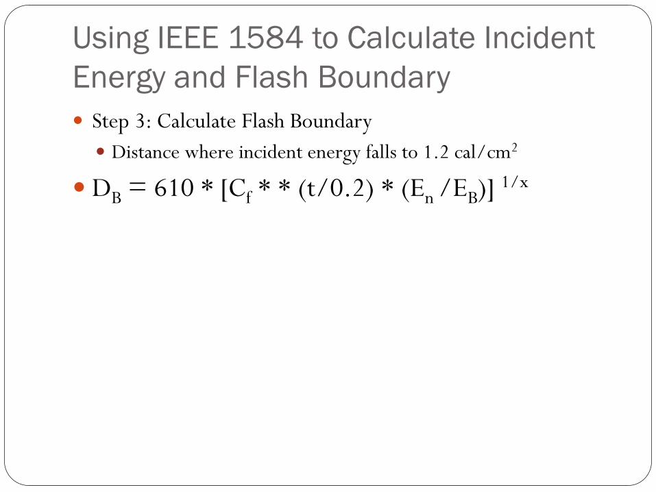
Step 3: Calculate Flash Boundary
Distance where incident energy falls to 1.2 cal/cm2
DB = 610 * [Cf * * (t/0.2) * (En /EB)] 1/x
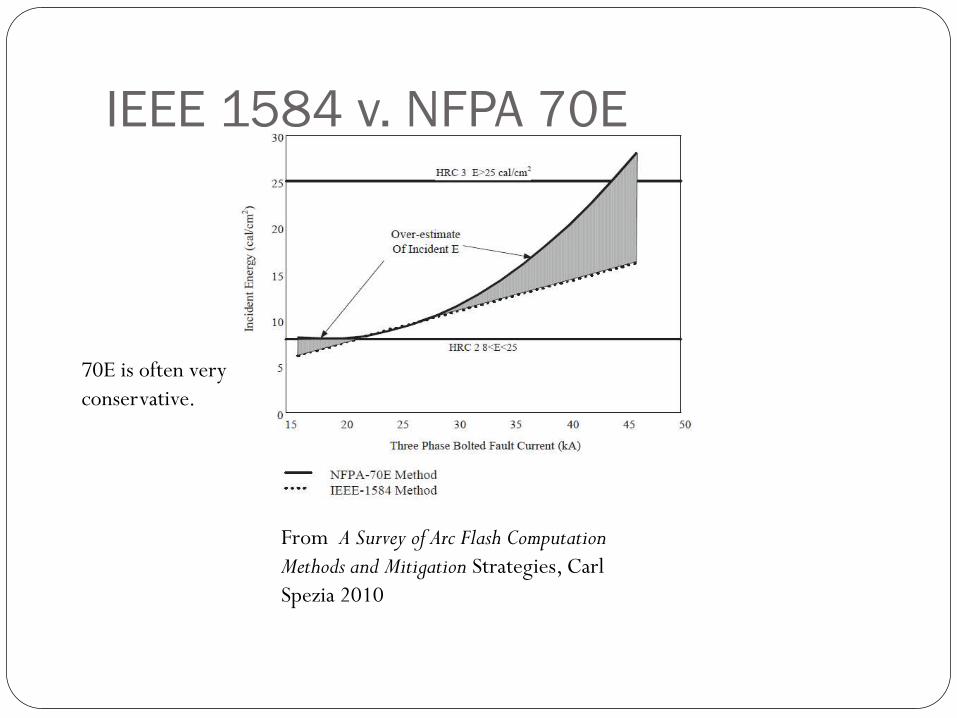
IEEE 1584 v. NFPA 70E
70E is often very
conservative.
From A Survey of Arc Flash Computation
Methods and Mitigation Strategies, Carl
Spezia 2010
Arc Flash Assessment Determination of degree of risk and precautions required.
Arc flash incidents are “high cost/low probability events” (Spezia 2010) Injury, litigation, regulatory requirements
NIOSH DVD Arc Flash Awareness gives accounts from electrical workers
Assessing risk and benefits can be difficult
See, for example: http://www.nsc.org/safetyhealth/Pages/411resourcesImportanceofArcFlashSalisbury.aspx
Arc Flash Mitigation [Incident Energy] = K * time * F(fault current)/ D1.497
NFPA 70E for enclosures
Problem is caused by the intersection of factors Energy in the arc Fault current
Clearing Time (Time is more important than fault current)
Presence of personnel near the arc Proximity to the arc, ie. Working at close quarters Incident Energy α 1/D2 (Open area)
or 1/D1.5 (Enclosure)
Susceptibility of personnel to incident energy (PPE)
All of these factors can be addressed!
Minimizing Energy
Decrease fault current
Series reactance can lower fault current – but…
Lower current can slow clearing devices
Often not practical or cost effective
Minimizing Energy
Current Limiting Fuses
Must clear a short circuit fault in less than a half cycle
Because of fast melting and increased fuse impedance in the first
quarter cycle both time and peak current are greatly reduced.
Can greatly reduce incident energy (by more than a factor of
ten)
Only work within limited ranges. Great when you have one that
fits the application. IEEE 1584 and vendor web sites have
detailed ratings
Minimizing Energy
Fiber Optic Flash Sensors
Provide very fast arc detection - ~2 msec
Work in closed spaces such as switchgear
Readily available
Some newer digital relays have inputs for up to four optical arc
sensors
See Inshaw, C., & Wilson, R. A. , Western Protective Relay
Conference, 2004.
Minimizing Energy
Change Relay Settings During Maintenance or Other
Operations
Uses existing equipment
Requires coordination study
May increase system vulnerability during maintenance
Depends greatly on particular circumstances.
Limit Presence of Personnel Near Arcs
If you aren’t there you won’t get hurt.
Only work on energized equipment when absolutely
necessary
Look hard for any alternative.
Observe OSHA and NFPA guidelines and rules
Lockout/tagout!
Check that voltage is really not present.
Remote racking of breakers, Mimic panels, etc.
Arc resistant switchgear (any potential arc is shunted away
from personnel)
Limit Presence of Personnel Near Arcs
Use Time Delay Trip and Close Control Switches in
Metalclad Switchgear
Provide 10 to 30 second delay from instigation of operation
to actual switching.
Discrete switch solution from Electroswitch
Also available in some newer digital protective relays
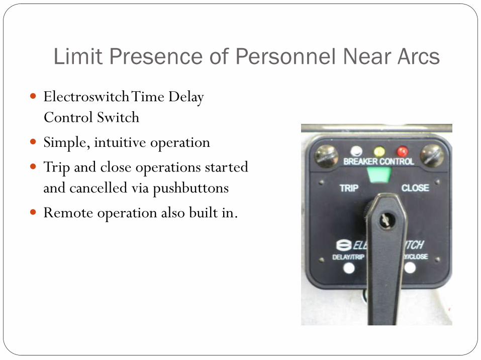
Limit Presence of Personnel Near Arcs
Electroswitch Time Delay
Control Switch
Simple, intuitive operation
Trip and close operations started
and cancelled via pushbuttons
Remote operation also built in.
Increase Distance of Personnel to Arc
For metalclad this often means operating a control switch
remotely.
Homegrown solutions
Hot sticks
Rope
Other
Increase Distance of Personnel to Arc
The Chicken Switch
Clamps on to existing switch handle.
Disadvantages: Has to be found each time
you need to operate the switch
Needs careful installation to avoid breaking the switch handle
Protect Personnel Subject to Arc Flash
This is the last line of defense! It is there to protect against
life threatening injury.
It is important to specify the PPE reasonably accurately.
Too little protection can result in disaster
Overprotection reduces worker mobility and vision, causing
other problems.
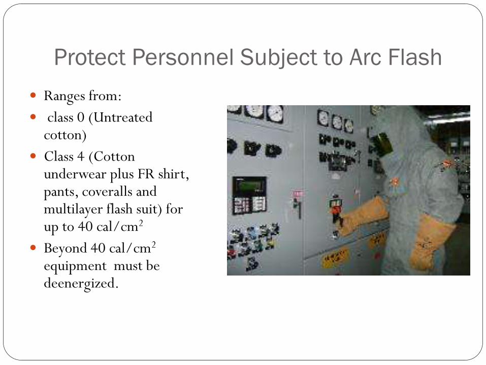
Protect Personnel Subject to Arc Flash
Ranges from:
class 0 (Untreated cotton)
Class 4 (Cotton underwear plus FR shirt, pants, coveralls and multilayer flash suit) for up to 40 cal/cm2
Beyond 40 cal/cm2
equipment must be deenergized.
Arc Flash Mitigation
Solvable problem
Better standards and information (IEEE 1584 revision are on
the way.
Information is readily available.
Questions?