applying sel differential relays - peak measure differential protection presentation objectives....
TRANSCRIPT

Copyright © SEL 2016
Applying SEL Differential RelaysIntroduction to Transformer
Differential Protection

• Explain challenges of transformer differential protection • Understand need for tap, phase, and zero-sequence
compensation and how they work• Understand how transformer differential relays are
made secure for inrush and overexcitation
Transformer DifferentialProtection Presentation Objectives

Differential Protection is Easy in Theory
Kirchhoff’s Current Law (KCL):n
kk 1
I 0
1
2 3

• Current magnitude mismatch • Phase shift across transformer• Zero-sequence sources• Energization inrush• Overexcitation• Unequal CT performance
Challenges to TransformerDifferential Protection

Differential Protection Principle

Differential Protection Principle

Current Magnitude and Phase Angle Difference Compensation
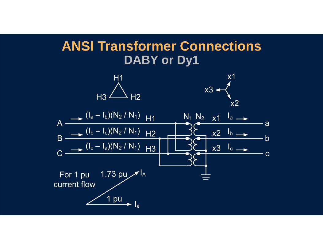
ANSI Transformer ConnectionsDABY or Dy1
1 2a b 2 1
b c 2 1
c a 2 1
a
b
c
a
A

ANSI Transformer ConnectionsYDAC or Yd1

Secondary Currents
SECSEC

Result of Uncompensated Phase Shift

Traditional Compensation

CTR1 and CTR2 Ideal Relationship
Not always possible with standard CT ratios
2
1 1 2
11 2
2
12 1
2
N 1 1N CTR CTRN CTR CTRN
kVCTR 3 CTRkV

• EM relays provide limited magnitude compensation• SEL relays provide magnitude and phase-shift
compensation (SEL-387 considers not only ANSI / IEEE standard connections, but all possible connections)
Compensation With Relays

• Current magnitude is transformed (transformer is constant KVA device) kVH • Ihigh-side = kVL • Ilow-side
Ihigh-side ≠ Ilow-side
• Load tap changer dynamically changes transformation ratio
Current Magnitude Mismatch

Tap Compensation
WDG
MVA •1000 • CTAP3 • kV • CTR
where:C = 1 for wye-connected CTsC = for delta-connected CTs3

Wye Connection Compensation
1TAP1
1TAP1
1TAP1
IAW1I1W1CTAP1
IBW1I2W1CTAP1
ICW1I3W1CTAP1

DAB Connection Compensation
1TAP2
1TAP2
1TAP2
1 (IAW2 IBW2)I1W2C •TAP2 3
1 (IBW2 ICW2)I2W2C •TAP2 3
1 (ICW2 IAW2)I3W2C •TAP2 3

DAC Connection Compensation
1TAP2
1TAP2
1TAP2
1 (IAW2 ICW2)I1W2C •TAP2 3
1 (IBW2 IAW2)I2W2C •TAP2 3
1 (ICW2 IBW2)I3W2C •TAP2 3

Compensation for Zero-Sequence Currents

Why Eliminate Zero-Sequence Current?

Removal Via Delta Connection

Restrained Differential Element

CT saturation and CT ratio error
Differential Protection PrincipleUnequal CT Performance

Percentage Differential Protection Principle
1 2
1 2IOP I I
1 2IRT 0.5 • I I

Differential Element Operate and Restraint Quantities
1 2I I
1 2I I2
1TAP1
1TAP2

Percentage Restraint Differential Characteristic

Percentage Restraint Differential Characteristic

Transformer Energization

C-Phase Inrush Current

Inrush Current
Cycles
Cycles1 2 3 4 5 6 7
1 2 3 4 5 6 7Prim
ary
Cur
rent
(A)
0
50
100P
erce
ntag
e of
Fund
amen
tal
0
20
40
60
80
Fundamental Frequency Magnitude
Second-Harmonic Magnitude
Second-Harmonic Percentage
Second-Harmonic Block Threshold

• Harmonic blocking• Harmonic restraint• DC blocking
Discriminating Internal FaultsVersus Inrush Conditions
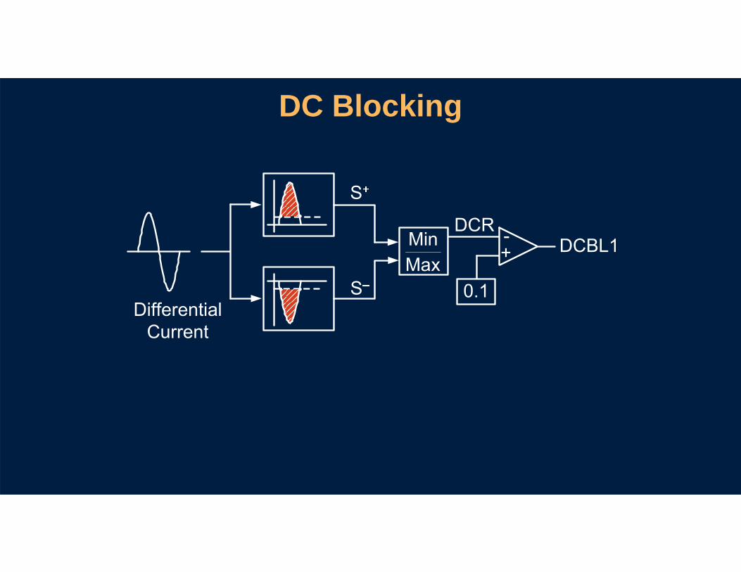
DC Blocking
MinMax

DC Blocking
+
+
–
+
–

DC Blocking
+ +
–
+
–

Inrush Conditions (Blocking)

Inrush Conditions (Restraint)

Unrestrained Differential Element

• Element instantaneously trips on magnitude of differential current No percentage restraint
No harmonic block
• CT saturation includes harmonics
Unrestrained Element

Transformer Overexcitation

Excitation Current From Testing150 Percent Overvoltage
Prim
ary
Cur
rent
(A)
Cycles
0.5 1 1.5 2 2.5 3–60
–40
–20
0
20
40
60
0

Fifth-Harmonic Content in Excitation Current
Frequency Component
Magnitude (primary A) Percent of Nominal
Fundamental 22.5 52.0
3rd 11.1 26.0
5th 4.9 11.0
7th 1.8 4.0

Excitation Current Harmonics
0
10
20
30
40
50
60
70
80
100 110 120 130 140 150 160

Application Considerations

Paralleling CTs on Restraint Input

Paralleling CTs on Restraint Input

Paralleling Transformers Sympathetic Inrush

• Know that third winding may not be rated at same MVA as main windings
• Set taps on multirestraint relay Work through matching taps in pairs
Be sure to use same MVA base for each tap calculation
Setting Taps for Three-Winding Transformers

Restricted Earth Fault (REF) Protection

Protect Windings Close to Neutral

Protection Basics – Why Use REF Protection?

• Thermal model • Through-fault monitoring
Prevention Before Protection

What Causes Transformer Overheating?

What Does Overheating Do?

Prevention Basics –Control Fan Banks
Ambient Temperature
Top-Oil Temperature
Temperature Data
Cooling Stage Control
Thermal Model

Why Enable Through-Fault Monitoring?

Track Through Faults Transformer Has
Experienced

Thermal Model
Prevention Basics –Enable Through-Fault Monitoring

Questions?