applications of polymer matrix composites in · pdf fileapplications of polymer matrix...
TRANSCRIPT
Applications of Polymer Matrix Composites in Extreme
Environments
Dr. Maciej S. KumosaJohn Evans Professor
Department of Mechanical and Materials EngineeringUniversity of Denver
May 14, 2009
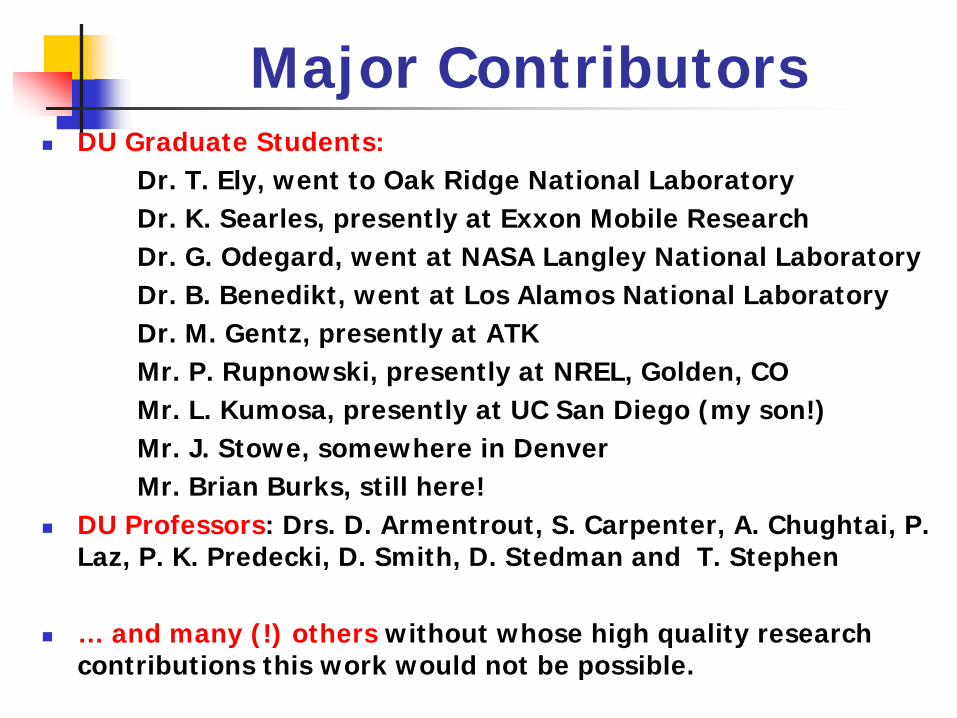
Major ContributorsDU Graduate Students:
Dr. T. Ely, went to Oak Ridge National LaboratoryDr. K. Searles, presently at Exxon Mobile ResearchDr. G. Odegard, went at NASA Langley National LaboratoryDr. B. Benedikt, went at Los Alamos National LaboratoryDr. M. Gentz, presently at ATKMr. P. Rupnowski, presently at NREL, Golden, COMr. L. Kumosa, presently at UC San Diego (my son!)Mr. J. Stowe, somewhere in DenverMr. Brian Burks, still here!
DU Professors: Drs. D. Armentrout, S. Carpenter, A. Chughtai, P. Laz, P. K. Predecki, D. Smith, D. Stedman and T. Stephen
… and many (!) others without whose high quality research contributions this work would not be possible.

AbstractIn this work, potential problems with the application of polymermatrix composites (PMC) in extreme environments are discussed.
Then, four specific examples of the applications of PMCs in highvoltage (composite insulators), high temperature (aerospacecombustion chambers), high ozone (composite conductors) andhigh moisture (cooling towers) situations are evaluated.
This research has been supported since 1992 by the NationalScience Foundations (3 grants), the Air Force of Office ofScientific Research (5 grants), the Electric Power ResearchInstitute (6 large contracts), NASA Glenn (3 grants) and aconsortium of large US utilities (15 grants and contracts from:Bonneville Power Administration, Western Are PowerAdministration, Alabama Power Company, Pacific gas &Electric,Tri-State, Arizona Public Service, National Rural ElectricCooperative Association), and NGK Japan.
Total funding for this research – approx. $3milion
Going to Extremes
PMCs can be highly desirable materialsbecause of their excellent specificproperties. However, these properties canbe seriously compromised if the compositesare subjected to extreme environments suchas:
very high and low temperatures,chemical exposures in corrosive environments(acidic and alkaline),extreme mechanical loads (high stresses, fatigue,residual stresses),exposure to oxygen, ozone, UV, pollution, etc.
Going to ExtremesWhile any of these extreme conditions willnegatively affect the durability of thesecomposites, it is the combination of morethan one that may have the most drasticeffects (synergistic effects).A comprehensive description of variousapplications of PMCs in extremeenvironments and associated with thempotential problems can be found in [1].
[1] Committee on Durability and Life Prediction of Polymer MatrixComposites in Extreme Environments, Going to Extremes: Meeting theEmerging Demand for Durable Polymer Matrix Composites, TheNational Academies Press, Washington DC, ISBN: 0-309-55235-4,2005, USA.
Aging/Degradation of Polymers
All polymers are ultimately susceptible to chemical degradation under exposure to various conditions even in commonly encountered environments!Polymers will especially rapidly degrade in extreme environments!When exposed to high temperatures, water, oxygen, ozone, UV, etc., weak Wan der Waals bonds will break.Bond breaking may also occur in polymer backbone bonds to lower the average length of the polymer chain.
Bond rupture (scission) will significantly reduce mechanical, electrical and thermal properties of
polymers and their composites with glass, carbon, Kevlar, boron, etc. fibers.
Some Examples of Degradation Mechanisms in PMC
Glass fibers will age depending on the presence of moisture, pollution, stress, time, temperature, composition of the glass, the presence of surface flaws, etc. Under certain moisture/acid conditions glass fibers, including E-glass fibers, will corrode and their mechanical properties will be grossly compromised. Carbon fibers are much more stable than glass fibers. If water is allowed inside a PMC composite, it will cause reversible and irreversible changes in the resin properties. The reversible changes are: plasticization (making polymers more compliant) and swelling, whereas the irreversible changes are: too much swelling, hydrolysis and micro-cracking. The chemical composition of polymers strongly influences both the solubility of water in the resin as well as its susceptibility towards hydrolysis.Water will damage interfaces in GRP composites (and other PMC composites as well).
Aging/Degradation of PMCFailure predictions of PMC structures are extremely difficult to perform, especially for long periods of time!Most of the available experimental data for PMC’s subjected to extreme environments are either unavailable or only very short term (max a few years). There are essentially an infinite number of combinations of various environmental factors with equally infinite number of potential final degradation effects on a PMC. Analytical methods such as Molecular Dynamics/Mechanics, “Ab initio” methods, Monte Carlo, etc. are in their infancy as far as their usefulness to predict polymer/PMC degradation for long time periods.
Failure predictions of polymers and their composites subjected to extreme environments is currently one of the fastest developing research areas not only in
the US but also abroad.

Molecular Dynamics Simulation of Polyethylene
Stowe, J., Predecki, P., Laz, P., Burks, B. and Kumosa, M., “Probabilistic Molecular Dynamics Evaluation of the Stress-Strain Behavior of Polyethylene”, Acta Materialia 57 (2009) 3615–3622
5000 united atoms2500 united atoms
100 united atoms 500 united atoms 1250 united atoms
5000 united atoms2500 united atoms 5000 united atoms5000 united atoms2500 united atoms2500 united atoms
100 united atoms 500 united atoms 1250 united atoms100 united atoms100 united atoms 500 united atoms500 united atoms 1250 united atoms1250 united atoms
Young’s modulus of polyethylene as a function of the
number of molecules for 2500 CH2 atoms
MD models of polyethylene
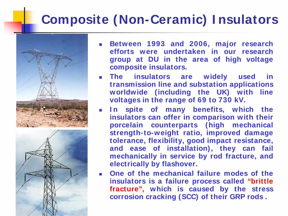
Between 1993 and 2006, major researchefforts were undertaken in our researchgroup at DU in the area of high voltagecomposite insulators.The insulators are widely used intransmission line and substation applicationsworldwide (including the UK) with linevoltages in the range of 69 to 730 kV.In spite of many benefits, which theinsulators can offer in comparison with theirporcelain counterparts (high mechanicalstrength-to-weight ratio, improved damagetolerance, flexibility, good impact resistance,and ease of installation), they can failmechanically in service by rod fracture, andelectrically by flashover.One of the mechanical failure modes of theinsulators is a failure process called “brittlefracture”, which is caused by the stresscorrosion cracking (SCC) of their GRP rods .
Composite (Non-Ceramic) Insulators
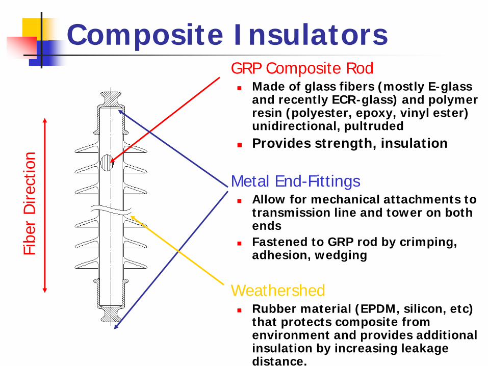
Composite InsulatorsGRP Composite Rod
Made of glass fibers (mostly E-glass and recently ECR-glass) and polymer resin (polyester, epoxy, vinyl ester) unidirectional, pultrudedProvides strength, insulation
Metal End-FittingsAllow for mechanical attachments to transmission line and tower on both endsFastened to GRP rod by crimping, adhesion, wedging
WeathershedRubber material (EPDM, silicon, etc) that protects composite from environment and provides additional insulation by increasing leakage distance.
Fibe
r D
irect
ion
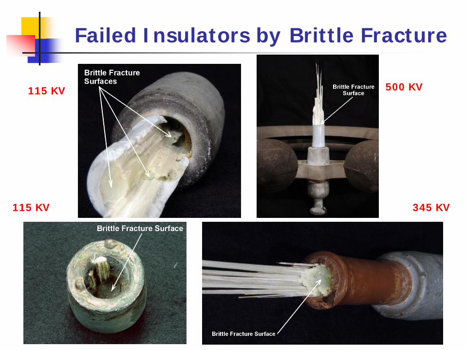
Failed Insulators by Brittle Fracture
115 KV 500 KV
115 KV 345 KV
Brittle Fracture Characteristics
The reason why the brittle fracture problem has drawn so muchattention is not because of the number of brittle fracture failures,which has not been significant (?), but because of itscharacteristic features, which are:
the failure is catastrophic (!)
the failure is unpredictable (!); can occur after a fewmonths or after a few years of being in service
there are no reliable monitoring techniques (!) which couldbe used to monitor the insulators in service for potentialbrittle fracture failures and other mechanical failure modes
the causes of failures, if one reads the available literatureon this topic, are uncertain (!) due to a number of confusingjournal articles and conference presentations.
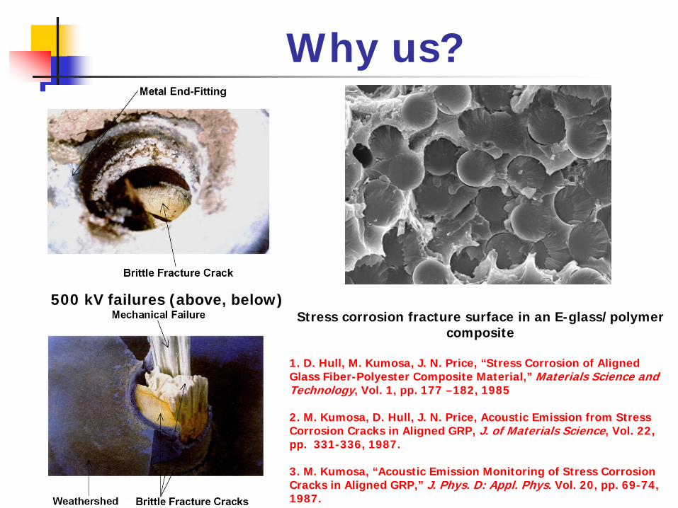
Why us?
Stress corrosion fracture surface in an E-glass/polymer composite
1. D. Hull, M. Kumosa, J. N. Price, “Stress Corrosion of Aligned Glass Fiber-Polyester Composite Material,” Materials Science and Technology, Vol. 1, pp. 177 –182, 1985
2. M. Kumosa, D. Hull, J. N. Price, Acoustic Emission from Stress Corrosion Cracks in Aligned GRP, J. of Materials Science, Vol. 22, pp. 331-336, 1987.
3. M. Kumosa, “Acoustic Emission Monitoring of Stress Corrosion Cracks in Aligned GRP,” J. Phys. D: Appl. Phys. Vol. 20, pp. 69-74, 1987.
500 kV failures (above, below)

Super Extreme EnvironmentHigh voltage: up to 730kV (usually less than 500kV), huge field gradients (1kV/cm and higher)Discharges: Corona discharges, partial dischargesPollution: ozone, air, sulfuric acid, nitric acid, acid rain, iron rust, etc.Moisture: rain, moist air, internal moisture Mechanical loads: large static, aeolian vibrations, galloping, overcrimpoingTime - desirable service time 50 yearsIncompetent; manufacturers, maintains crews, managers, scientists, etcOthers, still to be determined

Brittle Fracture-Stress Corrosion Cracking
Process by which E-glass fibers in a composite crack under stress
SCC is the individual process by which E-glass fibers are weakened in acidic environments.Acid causes the leaching out of large Ca+ and Al+ ions and replacing them with small H+ ions, severely weakening the chemical structure of glass fibersWeakened fibers develop tensile stresses and under mechanical tensile loads easily break.
GlassFiber
Al+
Ca+
H+
H+
H+
H+
H+
H+
Ion Leaching
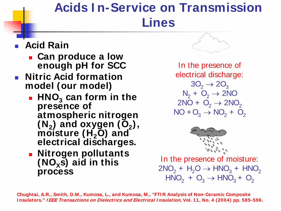
Acids In-Service on Transmission Lines
Acid RainCan produce a low enough pH for SCC
Nitric Acid formation model (our model)
HNO3 can form in the presence of atmospheric nitrogen (N2) and oxygen (O2), moisture (H2O) and electrical discharges.Nitrogen pollutants (NOXs) aid in this process
In the presence ofelectrical discharge:
3O2 → 2O3N2 + O2 → 2NO
2NO + O2 → 2NO2NO +O3 → NO2 + O2
In the presence of moisture:2NO2 + H2O → HNO3 + HNO2
HNO2 + O3 → HNO3 + O2
Chughtai, A.R., Smith, D.M., Kumosa, L., and Kumosa, M., “FTIR Analysis of Non-Ceramic Composite Insulators.” IEEE Transactions on Dielectrics and Electrical Insulation, Vol. 11, No. 4 (2004) pp. 585-596.
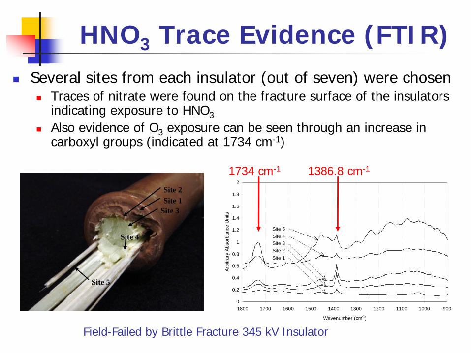
HNO3 Trace Evidence (FTIR)Several sites from each insulator (out of seven) were chosen
Traces of nitrate were found on the fracture surface of the insulators indicating exposure to HNO3
Also evidence of O3 exposure can be seen through an increase in carboxyl groups (indicated at 1734 cm-1)
0
0.2
0.4
0.6
0.8
1
1.2
1.4
1.6
1.8
2
900100011001200130014001500160017001800
Wavenumber (cm-1)
Arbi
trary
Abs
orba
nce
Uni
ts
Site 1
Site 5Site 4
Site 2Site 3
Site 2Site 1
Site 3
Site 4
Site 5
1386.8 cm-1
Field-Failed by Brittle Fracture 345 kV Insulator
1734 cm-1
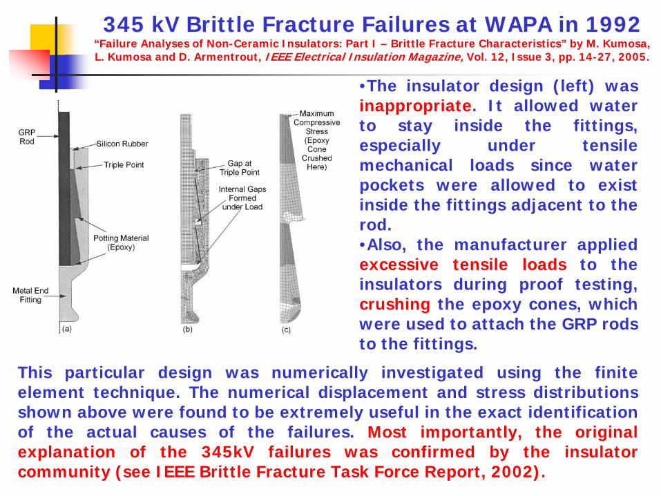
This particular design was numerically investigated using the finiteelement technique. The numerical displacement and stress distributionsshown above were found to be extremely useful in the exact identificationof the actual causes of the failures. Most importantly, the originalexplanation of the 345kV failures was confirmed by the insulatorcommunity (see IEEE Brittle Fracture Task Force Report, 2002).
345 kV Brittle Fracture Failures at WAPA in 1992 “Failure Analyses of Non-Ceramic Insulators: Part I – Brittle Fracture Characteristics” by M. Kumosa, L. Kumosa and D. Armentrout, IEEE Electrical Insulation Magazine, Vol. 12, Issue 3, pp. 14-27, 2005.
•The insulator design (left) wasinappropriate. It allowed waterto stay inside the fittings,especially under tensilemechanical loads since waterpockets were allowed to existinside the fittings adjacent to therod.•Also, the manufacturer appliedexcessive tensile loads to theinsulators during proof testing,crushing the epoxy cones, whichwere used to attach the GRP rodsto the fittings.
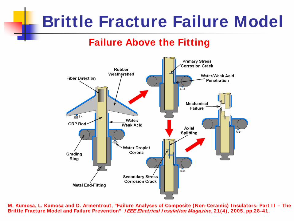
Brittle Fracture Failure ModelFailure Above the Fitting
M. Kumosa, L. Kumosa and D. Armentrout, “Failure Analyses of Composite (Non-Ceramic) Insulators: Part II – TheBrittle Fracture Model and Failure Prevention” IEEE Electrical Insulation Magazine, 21(4), 2005, pp.28-41.
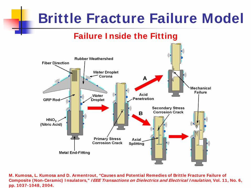
Brittle Fracture Failure ModelFailure Inside the Fitting
M. Kumosa, L. Kumosa and D. Armentrout, “Causes and Potential Remedies of Brittle Fracture Failure of Composite (Non-Ceramic) Insulators,” IEEE Transactions on Dielectrics and Electrical Insulation, Vol. 11, No. 6, pp. 1037-1048, 2004.
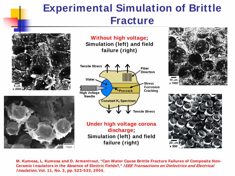
Experimental Simulation of Brittle Fracture
Without high voltage;Simulation (left) and field
failure (right)
Under high voltage corona discharge;
Simulation (left) and field failure (right)
M. Kumosa, L. Kumosa and D. Armentrout, “Can Water Cause Brittle Fracture Failures of Composite Non-Ceramic Insulators in the Absence of Electric Fields?,” IEEE Transactions on Dielectrics and Electrical Insulation, Vol. 11, No. 3, pp. 523-533, 2004.

Resistance to SCCResistance of the GRP composites to SCC is dominated by several critical material properties including:
Surface Fiber ExposureDictated by how many fibers are exposed on the surface
Fracture ToughnessRelated to the hardness of the resin
Moisture/Acid AbsorptionDetermines how fast moisture/acid can move in a composite
Innate Fiber ResistanceCertain types of glass fibers (ECR-glass also called boron free E-glass) are very resistant to corrosionThese fibers do not rely on the resin for protection from corrosive environments (however, they contain seeds (voids) which can affect their electrical properties).
Kumosa, L., Armentrout, D. and Kumosa, M. “An Evaluation of the Critical Conditions for the Initiation of Stress Corrosion Cracking in Unidirectional E-glass/Polymer Composites.” Composites Science & Technology, 61(4): 615-623, 2001.
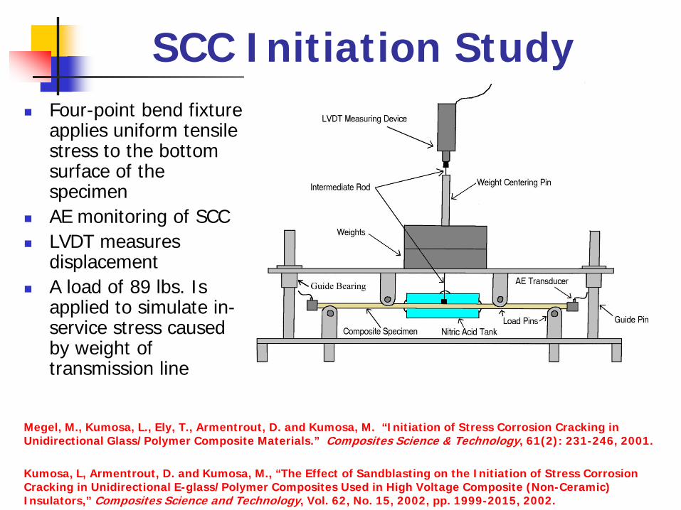
SCC Initiation StudyFour-point bend fixture applies uniform tensile stress to the bottom surface of the specimenAE monitoring of SCCLVDT measures displacementA load of 89 lbs. Is applied to simulate in-service stress caused by weight of transmission line
Megel, M., Kumosa, L., Ely, T., Armentrout, D. and Kumosa, M. “Initiation of Stress Corrosion Cracking in Unidirectional Glass/Polymer Composite Materials.” Composites Science & Technology, 61(2): 231-246, 2001.
Kumosa, L, Armentrout, D. and Kumosa, M., “The Effect of Sandblasting on the Initiation of Stress Corrosion Cracking in Unidirectional E-glass/Polymer Composites Used in High Voltage Composite (Non-Ceramic) Insulators,” Composites Science and Technology, Vol. 62, No. 15, 2002, pp. 1999-2015, 2002.
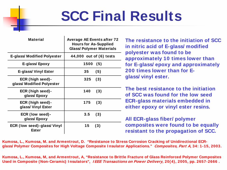
SCC Final ResultsMaterial Average AE Events after 72
Hours for As-Supplied Glass/Polymer Materials
E-glass/Modified Polyester 44,000 out of (6) tests
E-glass/Epoxy 1500 (5)
E-glass/Vinyl Ester 35 (5)
ECR (high seed)-glass/Modified Polyester
325 (3)
ECR (high seed)-glass/Epoxy
140 (3)
ECR (high seed)-glass/Vinyl Ester
175 (3)
ECR (low seed)-glass/Epoxy
3.5 (3)
ECR (low seed)-glass/Vinyl Ester
15 (3)
Kumosa, L., Kumosa, M. and Armentrout, D. “Resistance to Stress Corrosion Cracking of Unidirectional ECR-glass/Polymer Composites for High Voltage Composite Insulator Applications.” Composites, Part A, 34: 1-15, 2003.
Kumosa, L., Kumosa, M, and Armentrout, A, “Resistance to Brittle Fracture of Glass Reinforced Polymer Composites Used in Composite (Non-Ceramic) Insulators”, IEEE Transactions on Power Delivery, 20(4), 2005, pp. 2657-2666 .
The resistance to the initiation of SCC in nitric acid of E-glass/modified polyester was found to be approximately 10 times lower than for E-glass/epoxy and approximately 200 times lower than for E-glass/vinyl ester.
The best resistance to the initiation of SCC was found for the low seed ECR-glass materials embedded in either epoxy or vinyl ester resins.
All ECR-glass fiber/polymer composites were found to be equally resistant to the propagation of SCC.
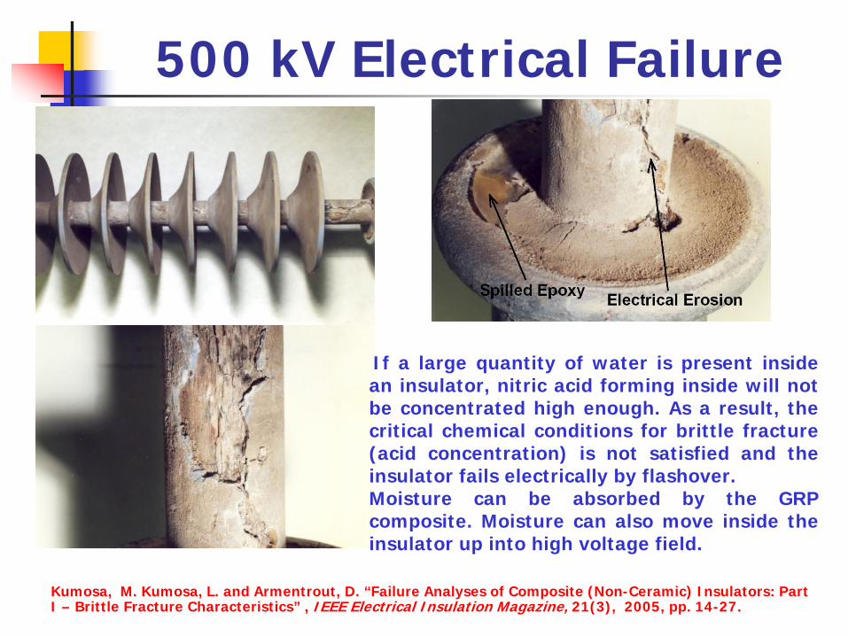
500 kV Electrical Failure
If a large quantity of water is present insidean insulator, nitric acid forming inside will notbe concentrated high enough. As a result, thecritical chemical conditions for brittle fracture(acid concentration) is not satisfied and theinsulator fails electrically by flashover.Moisture can be absorbed by the GRPcomposite. Moisture can also move inside theinsulator up into high voltage field.
Kumosa, M. Kumosa, L. and Armentrout, D. “Failure Analyses of Composite (Non-Ceramic) Insulators: Part I – Brittle Fracture Characteristics” , IEEE Electrical Insulation Magazine, 21(3), 2005, pp. 14-27.

Electrical Failure in JapanMaciej:
Your assistance on the insulator failure on the Japanese bullet train was extremely useful to Glasforms. The information referenced in the publication, "Brittle Fracture of Non-Ceramic Suspension Insulators with Epoxy Cone Fittings" served as the basis for the failure due not to the rod, but to the end fitting design and the iron and zinc contaminants found in the failed insulator. Thank you again, your input not only helped in diagnosing the problem, but basically eliminated a large potential claim.
Best regards,
XXX, Ph.D.Executive Vice PresidentXXX, Inc.July 2004
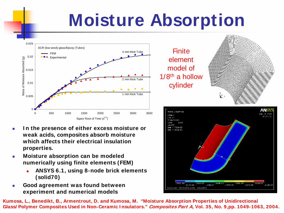
Moisture Absorption
In the presence of either excess moisture or weak acids, composites absorb moisture which affects their electrical insulation properties.Moisture absorption can be modeled numerically using finite elements (FEM)
ANSYS 6.1, using 8-node brick elements (solid70)
Good agreement was found between experiment and numerical models
0
0.005
0.01
0.015
0.02
0.025
0 500 1000 1500 2000 2500 3000 3500
Sqare Root of Time (s0.5)
Mas
s of
Moi
stur
e Ab
sorb
ed (g
)
ECR (low seed)-glass/Epoxy (Tubes)
FEMExperimental
1 mm thick Tube
2 mm thick Tube
4 mm thick Tube Finite element model of
1/8th a hollow cylinder
Kumosa, L., Benedikt, B., Armentrout, D. and Kumosa, M. “Moisture Absorption Properties of Unidirectional Glass/Polymer Composites Used in Non-Ceramic Insulators.” Composites Part A, Vol. 35, No. 9,pp. 1049-1063, 2004.
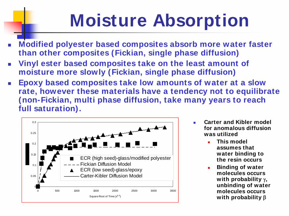
Moisture AbsorptionModified polyester based composites absorb more water faster than other composites (Fickian, single phase diffusion)Vinyl ester based composites take on the least amount of moisture more slowly (Fickian, single phase diffusion)Epoxy based composites take low amounts of water at a slow rate, however these materials have a tendency not to equilibrate (non-Fickian, multi phase diffusion, take many years to reach full saturation).
Carter and Kibler model for anomalous diffusion was utilized
This model assumes that water binding to the resin occursBinding of water molecules occurs with probability γ, unbinding of water molecules occurs with probability β
0
0.05
0.1
0.15
0.2
0.25
0.3
0 500 1000 1500 2000 2500 3000 3500
Square Root of Time (s0.5)
ECR (high seed)-glass/modified polyesterFickian Diffusion ModelECR (low seed)-glass/epoxyCarter-Kibler Diffusion Model

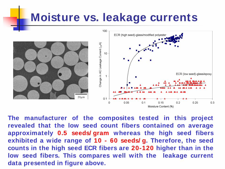
Moisture vs. leakage currents
The electrical properties (leakage current ) of the GRP composites can be examined as a function of moisture content.A prediction of the long term moisture properties and long-term insulation properties can also be evaluated using the Carter and Kibler model for anomalous diffusion.The effect of seeds in ECR fibers can be determined.
60°25 mm
12 kV for 60 sec.
64 mm
50 mm
Tubular Specimen
Brass Electrodes
25 mm
30 mm ±0.5 mm
Leakage Current Experimental Setup
Armentrout, D., Kumosa, M. and Kumosa, L., The Behavior of Composite Insulator GRP Rods Subjected to the Water Diffusion Electrical Test, IEEE Transactions on Dielectrics and Electrical Insulation, IEEE Transactions on Dielectrics and Electrical Insulation, Vol. 11, No. 3 (2004) pp. 503-522.
Kumosa, L., Armentrout, D., Benedikt, B. and Kumosa, M., “High Voltage Testing of Hollow Core Glass/Polymer Composite Rods under Controlled Moisture Diffusion Conditions.” IEEE Transactions on Dielectrics and Electrical Insulation, Vol. 12, No. 5 (2005) pp. 1043-1059 .
US patent 7327132

Moisture vs. leakage currents
y = 2.08x + 0.07R2 = 0.86
0
0.1
0.2
0.3
0.4
0.5
0.6
0.7
0 0.05 0.1 0.15 0.2 0.25 0.3
Moisture Content (%)
Cha
nge
in L
eaka
ge C
urre
nt (m
A)
Averaged Leakage Current vs. Moisture Content
Linear Trend Fit
(averaged Values from three specimens)
ECR (low seed)-glass/epoxy 4-mm Thick Hollow Core Rods
0
0.05
0.1
0.15
0.2
0.25
0.3
0 500 1000 1500 2000 2500 3000 3500Square Root of Time (s0.5)
Moi
stur
e C
onte
nt (%
)
0
0.1
0.2
0.3
0.4
0.5
0.6
0.7
0.8
Leakage Current, AC
(μ A)
Moisture AbsorptionNon-Fickian (Carter and Kibler) FitAC Leakage CurrentPredicted Leakage Current
ECR (low seed)-glass/epoxy 2-mm (Specimen #1)
Moisture and leakage current (vs. time) curves for a low
seed E-glass/epoxy composite (above).
Moisture vs. leakage current for a low seed E-glass/epoxy
composite (below).
Moisture vs. leakage currents
The manufacturer of the composites tested in this projectrevealed that the low seed count fibers contained on averageapproximately 0.5 seeds/gram whereas the high seed fibersexhibited a wide range of 10 - 60 seeds/g. Therefore, the seedcounts in the high seed ECR fibers are 20-120 higher than in thelow seed fibers. This compares well with the leakage currentdata presented in figure above.

Crimping Analysis
Schematic of Crimping3-D Non-linear FEM Model of Crimping
Kumosa, M., Han, Y. and Kumosa, L., "Fracture Analyses of Composite Insulators with Crimped End-Fittings: Part I- Non-Linear Finite Element Computations," Composites Science & Technology, Vol. 62, No. 9 (2002) pp. 1191-1207.
Kumosa, M., Armentrout, D., L. Kumosa, Han, Y. and Carpenter, S.H., "Fracture Analyses of Composite Insulators with Crimped End-Fittings: Part II- Suitable Crimping Conditions," Composites Science & Technology, Vol. 62, No. 9 (2002) pp. 1209-1221.
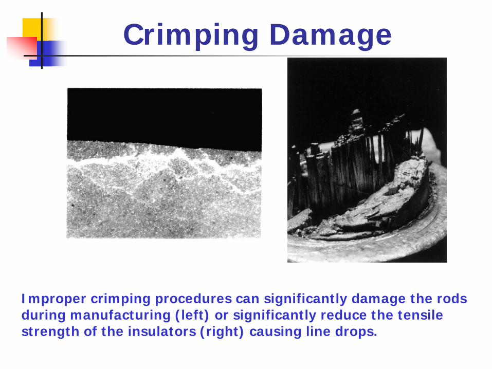
Crimping Damage
Improper crimping procedures can significantly damage the rods during manufacturing (left) or significantly reduce the tensile strength of the insulators (right) causing line drops.
Major Research Accomplishments
Major contributions to composite insulator technology have been made by us since 1993.
Explanation of 345 kV and 500 kV brittle fracture failuresexperienced by WAPA and PG&E,Identification of the type of acid responsible for brittle fracture,Simulation of brittle fracture with and without high voltage,Identification of several critical conditions leading to brittlefracture and other mechanical and electrical failure modes,Providing rankings of the commonly used GRP rod materials fortheir resistance to stress corrosion cracking (brittle fracture),moisture absorption, surface mechanical damage, leakagecurrents, ozone/water acid degradation, etc.Recommendation of numerous experimental and numericalprocedures critical in the insulator design process.
FULLY APPROVED BY IEEE in 10 IEEE REVIEW PAPERS!!!
Our Insulator Website
If you want to know more about our research on high voltage insulators (and our other research projects, research facilities, etc.) go to:
http://www.engr.du.edu/CFAMS/CFAMS_Downloads.htm

Combustion Chamber
Advanced high temperature graphite/polyimide composites were evaluated for aerospace applications. The composite investigated in this project were used to manufacture and successfully test a Rocket
Based Combined Cycle (RBCC) third-generation, reusable liquid propellant rocket engine, which is one possible engine for a future
single-stage-to-orbit vehicle.Jointly with NASA Glenn, Boeing and 24 other US companies.
Rocket Based Combined CycleCombustion Chamber Support Structure
Reusable Space Vehicles
Mechanical behavior of unidirectional and wovengraphite/polyimide composites based on medium(T650-35) and high (M40J and M60J) modulusgraphite fibers with PMR-15 and PMR-II-50polyimide resins tested under biaxial sheardominated stress conditions over a temperaturerange of 20°C to 400°C has been investigated bothexperimentally and numerically.
Testing and Modeling of 8HS T650-35/PMR-15, 4HS M40J/PMR-II-50 and 4HS M60J/PMR-II-50
M. Kumosa et al., Comparison of the 45 off Axis and Iosipescu Shear Tests for Woven Fabric CompositeMaterials, Composites Technology & Research, Vol. 24 (2002) pp. 3-16.
M. Gentz et al., Mechanical Behavior of a Woven Graphite/PMR-15 Composite at Room and ElevatedTemperatures Determined from the ±45° Tensile and Iosipescu Shear Tests, Journal of CompositesTechnology & Research, Vol. 25, Issue 1 (2003) pp. 22-34.
M. Gentz, et al., In-Plane Shear Testing of Woven Graphite/Polyimide Composites with Medium and HighModulus Graphite Fibers at Room and 316°C Temperatures, Composites Science and Technology, Vol. 64(2004) pp. 203-220.
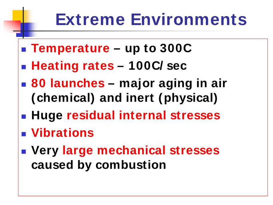
Extreme Environments
Temperature – up to 300CHeating rates – 100C/sec80 launches – major aging in air (chemical) and inert (physical)Huge residual internal stressesVibrationsVery large mechanical stressescaused by combustion
Graphite/Polyimide Composites
Graphite/polyimide composites are advanced thermosettingpolymer matrix composites with graphite reinforcement whichhave become highly relevant in the realm of high temperatureapplications. These composites have excellent specificproperties which remain stable up to temperatures as high as400°C. The upper service temperature of most graphite/epoxycomposites is limited to about 150-180°C.
Polyimide resins are available commercially with the tradenames PMR-15, PMR-II-50, VCAP-75, Avimid-R, Avimid-N,AMB-21 etc. PMR-15 is the polyimide that has been put tomaximum commercial use, primarily to its high glass-transition temperature (350°C).
The primary driving force for using graphite/polyimide composites is weight savings. They have a specific strength
three times higher (in the fiber directions) than titanium and other traditional aerospace materials.
Graphite/Polyimide Composites
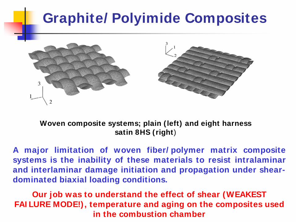
A major limitation of woven fiber/polymer matrix compositesystems is the inability of these materials to resist intralaminarand interlaminar damage initiation and propagation under shear-dominated biaxial loading conditions.
Our job was to understand the effect of shear (WEAKEST FAILURE MODE!), temperature and aging on the composites used
in the combustion chamber
Woven composite systems; plain (left) and eight harness satin 8HS (right)
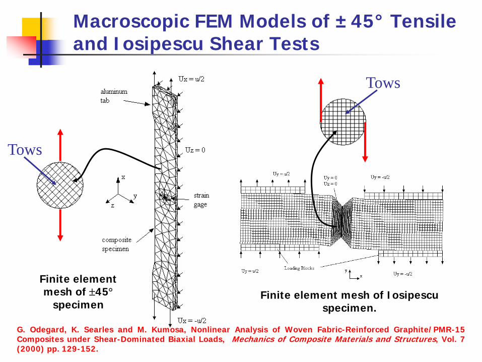
Macroscopic FEM Models of ±45° Tensile and Iosipescu Shear Tests
Finite element mesh of ±45°
specimenFinite element mesh of Iosipescu
specimen.
G. Odegard, K. Searles and M. Kumosa, Nonlinear Analysis of Woven Fabric-Reinforced Graphite/PMR-15Composites under Shear-Dominated Biaxial Loads, Mechanics of Composite Materials and Structures, Vol. 7(2000) pp. 129-152.
Tows
Tows
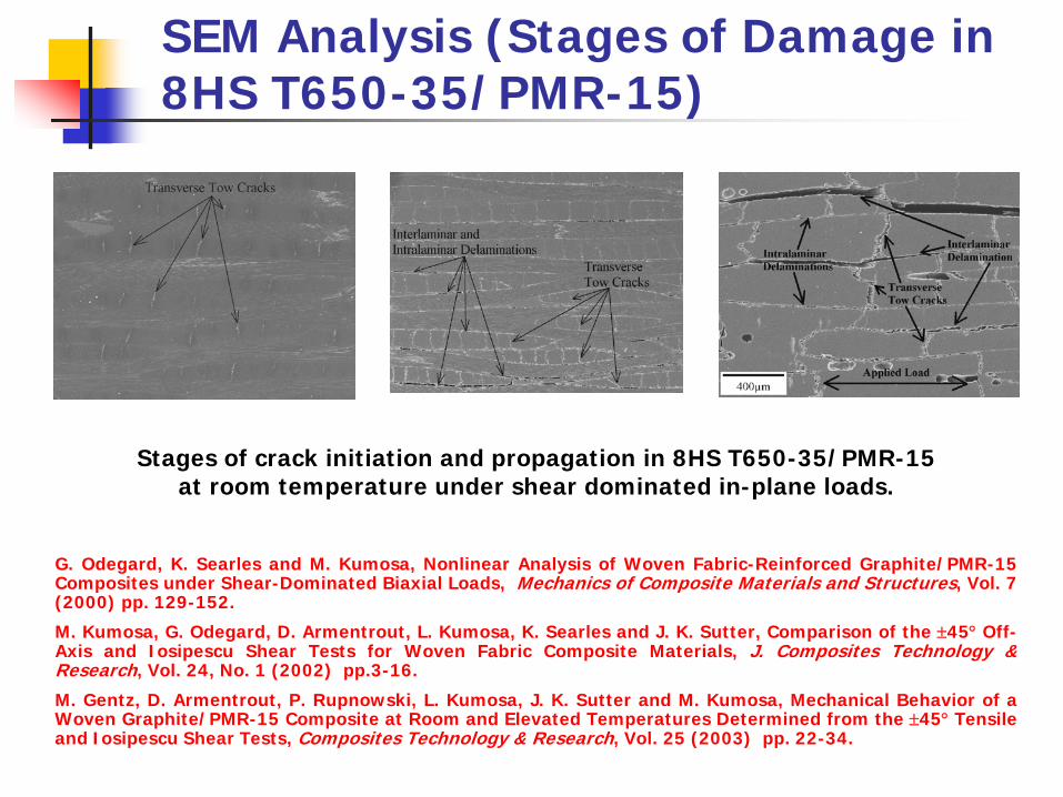
SEM Analysis (Stages of Damage in 8HS T650-35/PMR-15)
Stages of crack initiation and propagation in 8HS T650-35/PMR-15 at room temperature under shear dominated in-plane loads.
G. Odegard, K. Searles and M. Kumosa, Nonlinear Analysis of Woven Fabric-Reinforced Graphite/PMR-15Composites under Shear-Dominated Biaxial Loads, Mechanics of Composite Materials and Structures, Vol. 7(2000) pp. 129-152.
M. Kumosa, G. Odegard, D. Armentrout, L. Kumosa, K. Searles and J. K. Sutter, Comparison of the ±45° Off-Axis and Iosipescu Shear Tests for Woven Fabric Composite Materials, J. Composites Technology &Research, Vol. 24, No. 1 (2002) pp.3-16.
M. Gentz, D. Armentrout, P. Rupnowski, L. Kumosa, J. K. Sutter and M. Kumosa, Mechanical Behavior of aWoven Graphite/PMR-15 Composite at Room and Elevated Temperatures Determined from the ±45° Tensileand Iosipescu Shear Tests, Composites Technology & Research, Vol. 25 (2003) pp. 22-34.
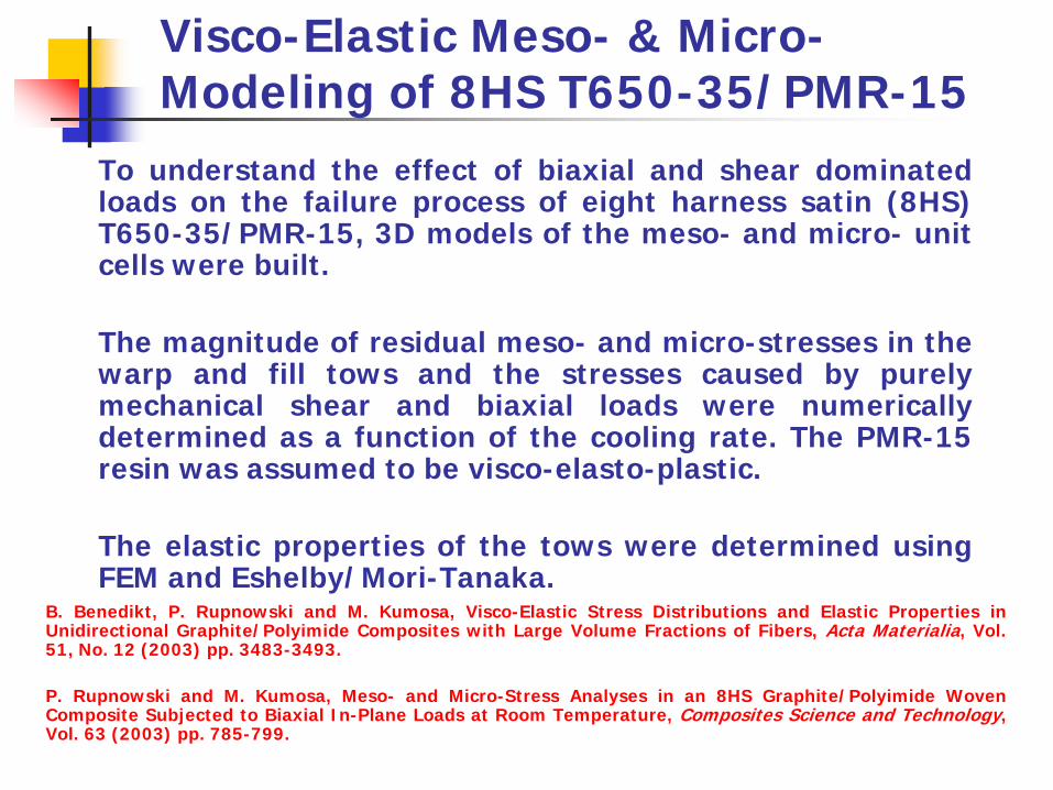
Visco-Elastic Meso- & Micro-Modeling of 8HS T650-35/PMR-15
To understand the effect of biaxial and shear dominatedloads on the failure process of eight harness satin (8HS)T650-35/PMR-15, 3D models of the meso- and micro- unitcells were built.
The magnitude of residual meso- and micro-stresses in thewarp and fill tows and the stresses caused by purelymechanical shear and biaxial loads were numericallydetermined as a function of the cooling rate. The PMR-15resin was assumed to be visco-elasto-plastic.
The elastic properties of the tows were determined usingFEM and Eshelby/Mori-Tanaka.
B. Benedikt, P. Rupnowski and M. Kumosa, Visco-Elastic Stress Distributions and Elastic Properties inUnidirectional Graphite/Polyimide Composites with Large Volume Fractions of Fibers, Acta Materialia, Vol.51, No. 12 (2003) pp. 3483-3493.
P. Rupnowski and M. Kumosa, Meso- and Micro-Stress Analyses in an 8HS Graphite/Polyimide WovenComposite Subjected to Biaxial In-Plane Loads at Room Temperature, Composites Science and Technology,Vol. 63 (2003) pp. 785-799.
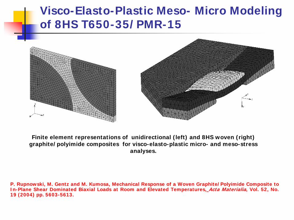
Visco-Elasto-Plastic Meso- Micro Modeling of 8HS T650-35/PMR-15
Finite element representations of unidirectional (left) and 8HS woven (right) graphite/polyimide composites for visco-elasto-plastic micro- and meso-stress
analyses.
P. Rupnowski, M. Gentz and M. Kumosa, Mechanical Response of a Woven Graphite/Polyimide Composite toIn-Plane Shear Dominated Biaxial Loads at Room and Elevated Temperatures, Acta Materialia, Vol. 52, No.19 (2004) pp. 5603-5613.
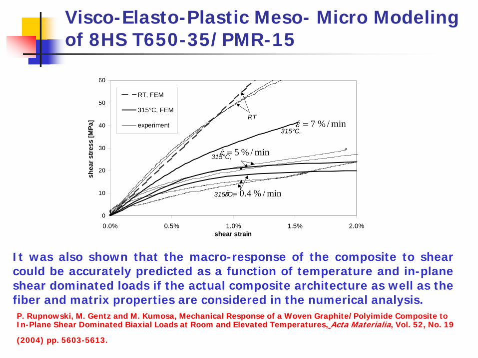
Visco-Elasto-Plastic Meso- Micro Modeling of 8HS T650-35/PMR-15
0
10
20
30
40
50
60
0.0% 0.5% 1.0% 1.5% 2.0%shear strain
shea
r str
ess
[MPa
]RT, FEM
315°C, FEM
experimentRT
min/%7=ε&
min/%5=ε&
315°C,
315°C,
min/%4.0=ε&315°C,
It was also shown that the macro-response of the composite to shearcould be accurately predicted as a function of temperature and in-planeshear dominated loads if the actual composite architecture as well as thefiber and matrix properties are considered in the numerical analysis.P. Rupnowski, M. Gentz and M. Kumosa, Mechanical Response of a Woven Graphite/Polyimide Composite to In-Plane Shear Dominated Biaxial Loads at Room and Elevated Temperatures, Acta Materialia, Vol. 52, No. 19
(2004) pp. 5603-5613.
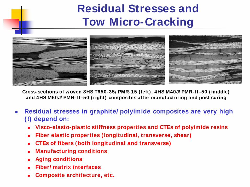
Residual Stresses andTow Micro-Cracking
Cross-sections of woven 8HS T650-35/PMR-15 (left), 4HS M40J/PMR-II-50 (middle) and 4HS M60J/PMR-II-50 (right) composites after manufacturing and post curing
Residual stresses in graphite/polyimide composites are very high(!) depend on:
Visco-elasto-plastic stiffness properties and CTEs of polyimide resinsFiber elastic properties (longitudinal, transverse, shear)CTEs of fibers (both longitudinal and transverse)Manufacturing conditionsAging conditionsFiber/matrix interfacesComposite architecture, etc.

An Evaluation of Elastic Properties and Coefficients of Thermal Expansion of Medium and
High Modulus Graphite Fibers
A methodology has been suggested for theevaluation of stiffness properties (longitudinal,transverse and shear) and coefficients of thermalexpansion (both longitudinal and transverse) ofmedium (T650-35) and high (M40J and M60J)modulus graphite fibers.
The methodology was subsequently used todetermine the stiffness and thermal properties ofthe fibers from the macroscopic input data ofunidirectional and woven composites based on thesame fibers embedded either in PMR-15 or PMR-II-50 polyimide resins.
P. Rupnowski, M. Gentz, J.K. Sutter and M. Kumosa, An Evaluation of Elastic Properties and Coefficients ofThermal Expansion of Graphite Fibers from Macroscopic Composite Input Data, Proceedings of the RoyalSociety, Vol. 461 (2005) pp. 347-369.
P. Rupnowski, M. Gentz, J. K. Sutter and M. Kumosa, An Evaluation of the Elastic Properties and ThermalExpansion Coefficients of Medium and High Modulus Graphite Fibers, Composites Part A; Applied Scienceand Manufacturing, Vol. 36 (2004) pp. 327-338.
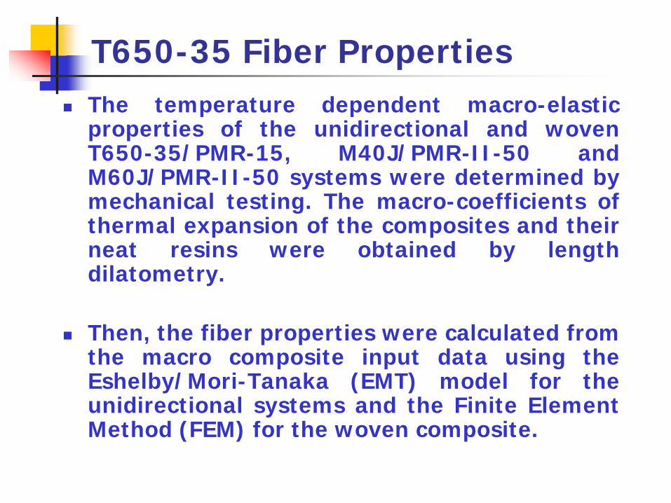
T650-35 Fiber PropertiesThe temperature dependent macro-elasticproperties of the unidirectional and wovenT650-35/PMR-15, M40J/PMR-II-50 andM60J/PMR-II-50 systems were determined bymechanical testing. The macro-coefficients ofthermal expansion of the composites and theirneat resins were obtained by lengthdilatometry.
Then, the fiber properties were calculated fromthe macro composite input data using theEshelby/Mori-Tanaka (EMT) model for theunidirectional systems and the Finite ElementMethod (FEM) for the woven composite.
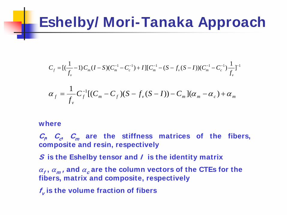
Eshelby/Mori-Tanaka Approach
mcmmvfmfv
f CISfSCCCf
αααα +−−−−−= − )]())()([(1 1
where
Cf, Cc, Cm are the stiffness matrices of the fibers,composite and resin, respectively
S is the Eshelby tensor and I is the identity matrix
αf , αm , and αc are the column vectors of the CTEs for the fibers, matrix and composite, respectively
fv is the volume fraction of fibers
1 1 1 1 1 11 1[( 1) ( )( ) ][ ( ( ))( ) ]f m m c m v m cv v
C C I S C C I C S f S I C Cf f
− − − − − −= − − − + − − − −

Macro- to Micro-Approach
Classical error analysis based on the Monte Carlo methodapplied to the inverse Eshelby/Tanaka-Mori model wasemployed to compute the uncertainty of indirect evaluation ofgraphite fiber properties.
INPUT DATA –composite and resin properties
OUTPUT DATA – probability distribution functions (pdf’s) of fiber properties
Monte Carlo method
+Micro-mechanic
model
P. Rupnowski, M. Gentz, J.K. Sutter and M. Kumosa, An Evaluation of Elastic Properties and Coefficients of Thermal Expansion of Graphite Fibers from Macroscopic Composite Input Data, Proceedings of the Royal Society, Vol. 461 (2005) pp. 347-369.
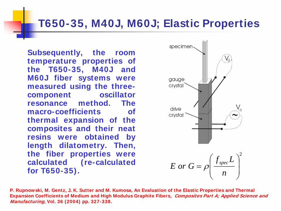
T650-35, M40J, M60J; Elastic Properties
Subsequently, the roomtemperature properties ofthe T650-35, M40J andM60J fiber systems weremeasured using the three-component oscillatorresonance method. Themacro-coefficients ofthermal expansion of thecomposites and their neatresins were obtained bylength dilatometry. Then,the fiber properties werecalculated (re-calculatedfor T650-35).
2
⎟⎟⎠
⎞⎜⎜⎝
⎛=
nLf
GorE specρ
P. Rupnowski, M. Gentz, J. K. Sutter and M. Kumosa, An Evaluation of the Elastic Properties and Thermal Expansion Coefficients of Medium and High Modulus Graphite Fibers, Composites Part A; Applied Science and Manufacturing, Vol. 36 (2004) pp. 327-338.
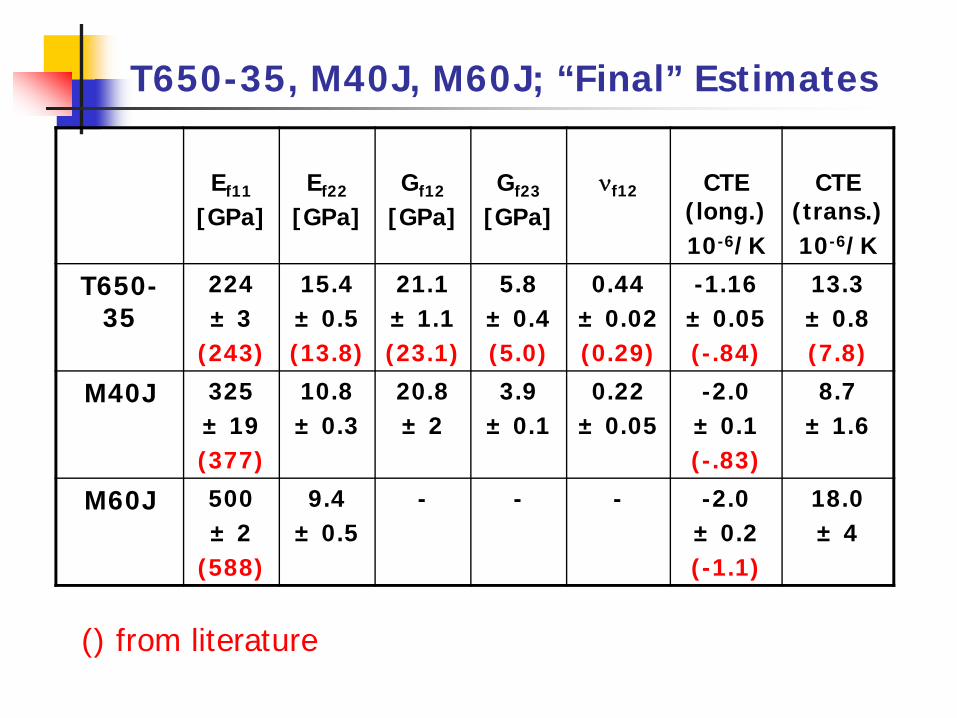
T650-35, M40J, M60J; “Final” Estimates
Ef11
[GPa]Ef22
[GPa]Gf12
[GPa]Gf23
[GPa]νf12 CTE
(long.)10-6/K
CTE (trans.)10-6/K
T650-35
224± 3
(243)
15.4± 0.5(13.8)
21.1± 1.1(23.1)
5.8± 0.4(5.0)
0.44± 0.02(0.29)
-1.16± 0.05(-.84)
13.3± 0.8(7.8)
M40J 325± 19(377)
10.8± 0.3
20.8± 2
3.9± 0.1
0.22± 0.05
-2.0± 0.1(-.83)
8.7± 1.6
M60J 500± 2
(588)
9.4± 0.5
- - - -2.0± 0.2(-1.1)
18.0± 4
() from literature
X-Ray Diffraction Tests on T650-35/PMR-15 Composites with Embedded Inclusions
Interlaminar residual thermal stresses inunidirectional and woven (8HS) T650-35/PMR-15composites were determined both experimentallyand numerically as a function of the manufacturingprocess.
Numerous XRD measurements were made todetermine residual strains and stresses inembedded Al and Ag inclusions placed in four ply8HS woven and 6 ply unidirectional graphite/PMR-15 composites.
B. Benedikt, M. Kumosa, P.K. Predecki, L. Kumosa, M.G. Castelli and J.K. Sutter, An Analysis of Residual ThermalStresses in a Unidirectional Graphite/PMR-15 Composite Based on the X-ray Diffraction Measurements,Composites Science and Technology, Vol. 61, No. 14 (2001) pp. 1977-1994.
B. Benedikt, P. Rupnowski, L. Kumosa, J. K. Sutter, P.K. Predecki and M. Kumosa, Determination of InterlaminarResidual Thermal Stresses in a Woven 8HS Graphite/PMR-15 Composite Using X-Ray Diffraction Measurements,Mechanics of Advanced Materials and Structures, Vol. 9 (2002) pp. 1-20.

X-Ray Diffraction Tests on T650-35/PMR-15 Composites with Embedded Inclusions
33
11
22
ψ
ϕ
Diffraction Plane Normal
ψϕεψϕεψεψϕε
ψϕεψϕεε ϕψϕψ
2sinsin2sincoscossinsin
sin2sinsincos
23132
3322
22
212
2211
0
0
+++
++=−
=d
dd
Lattice spacing in unstressed (do) and stressed (dϕψ) particles measured by XRD.
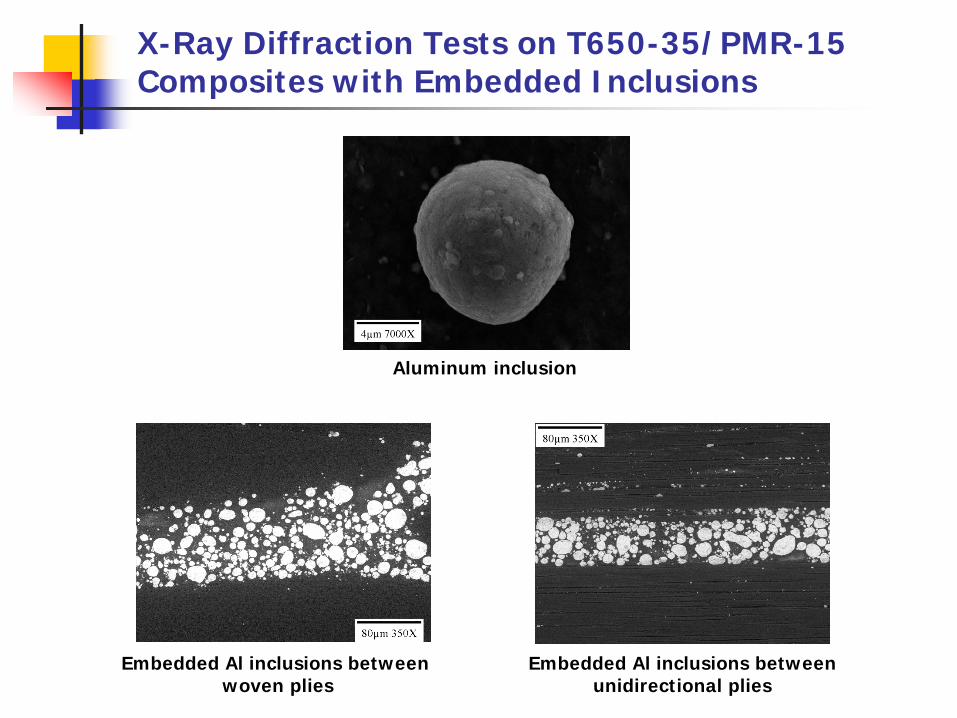
X-Ray Diffraction Tests on T650-35/PMR-15 Composites with Embedded Inclusions
Embedded Al inclusions betweenwoven plies
Aluminum inclusion
Embedded Al inclusions betweenunidirectional plies
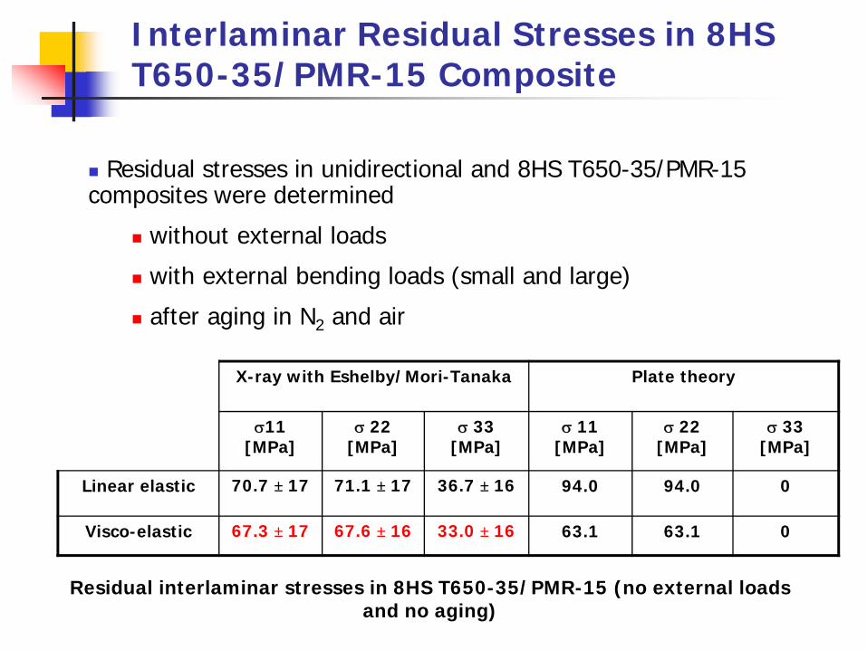
Interlaminar Residual Stresses in 8HS T650-35/PMR-15 Composite
X-ray with Eshelby/Mori-Tanaka Plate theory
σ11 [MPa]
σ 22 [MPa]
σ 33 [MPa]
σ 11 [MPa]
σ 22 [MPa]
σ 33 [MPa]
Linear elastic 70.7 ± 17 71.1 ± 17 36.7 ± 16 94.0 94.0 0
Visco-elastic 67.3 ± 17 67.6 ± 16 33.0 ± 16 63.1 63.1 0
Residual stresses in unidirectional and 8HS T650-35/PMR-15 composites were determined
without external loads
with external bending loads (small and large)
after aging in N2 and air
Residual interlaminar stresses in 8HS T650-35/PMR-15 (no external loads and no aging)

X-Ray Diffraction Experiments on Graphite Fiber/Polyimide Composites Subjected to Aging
(XRD) measurements of residual strains in embedded aluminumspherical inclusions were performed to evaluate the residualinterlaminar stresses in unidirectional and woven 8HS T650/PMR-15 composites subjected to aging either in air or nitrogen andexternal bending loads.
Unidirectional T650-35/PMR-15 system aged in nitrogen (left) and in air (right) for 1170 hours.
B. Benedikt et al. Determination of Interlaminar Residual Stresses in a Woven 8HS Graphite/PMR-15Composite Using X-ray Diffraction Measurements, Mechanics of Advanced Materials and Structures, Vol. 9(2002) pp. 375.B. Benedikt et al., , Analysis of Stresses in Aluminum Particles Embedded Inside Unidirectional and WovenGraphite/Polyimide Composites Subjected to Large Bending Loads, Mechanics of Advanced Materials andStructures, Vol. 11, No. 1 (2004) pp. 31-49.B. Benedikt et al., X-Ray Diffraction Experiments on Aged Graphite Fiber/Polyimide Composites withEmbedded Aluminum Inclusions, Composites Part A, Vol. 35 (2004) pp. 667-681.

2004 NASA Announcement
This is the first application for Rocketdyne of a high temperature polymer matrix composite in a space propulsioncomponent. Successful completion of this test will enable Rocketdyne to explore other applications for HT PMCs intheir engines. It is also the first time that a full-scale PMC structure has been tested at GASL. Experience gained fromthis testing will enable GASL to more easily test similar structures. In addition to Rocketdyne, this effort involved theparticipation of twenty-four companies (component designers, fabricators, resin/materials suppliers, etc.), universities(U of Dayton Research Institute, U of Denver), and the Air Force Materials Lab. This effort utilized GRC expertiseand facilities in the Life Prediction (5920), Structural Mechanics and Dynamics (5930) Branches, and Engineering andTechnical Services Directorate. This project was supported by the former HOTPC program and is currently funded byUEET-Highly Loaded Light Weight Compressors and Turbines.” [NASA Glen]
“A lightweight high temperature polymer matrixcomposite (HTPMC) combustor support chamberfor a Rocket Based Combined Cycle enginesuccessfully survived hot-fire testing at ATK-GASL. This testing concludes a three yearcollaboration between NASA Glenn and Boeing todesign, fabricate and test the support structure andfulfills a GPRA (Government Performance ReformAct) milestone for the UEET (Ultra-efficientEngine Program). The support structure wasprepared from a high temperature compositematerial, PMR-II-50. In addition to satisfying animportant technical milestone, this activity isnoteworthy because it constitutes a number of‘firsts.’
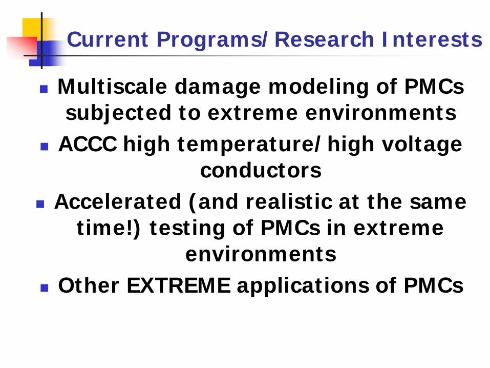
Current Programs/Research Interests
Multiscale damage modeling of PMCs subjected to extreme environments
ACCC high temperature/high voltage conductors
Accelerated (and realistic at the same time!) testing of PMCs in extreme
environmentsOther EXTREME applications of PMCs
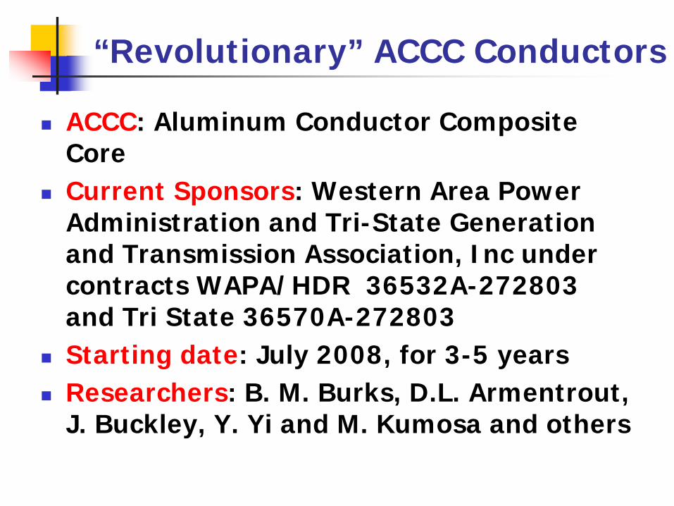
“Revolutionary” ACCC Conductors
ACCC: Aluminum Conductor Composite CoreCurrent Sponsors: Western Area Power Administration and Tri-State Generation and Transmission Association, Inc under contracts WAPA/HDR 36532A-272803 and Tri State 36570A-272803Starting date: July 2008, for 3-5 yearsResearchers: B. M. Burks, D.L. Armentrout, J. Buckley, Y. Yi and M. Kumosa and others
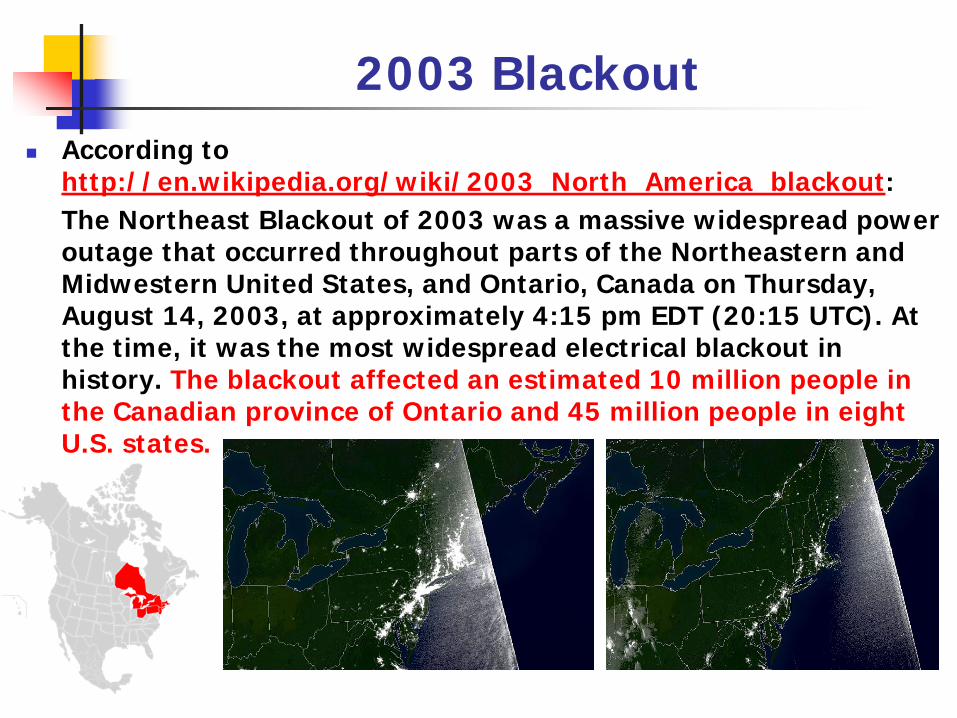
2003 BlackoutAccording to http://en.wikipedia.org/wiki/2003_North_America_blackout:The Northeast Blackout of 2003 was a massive widespread power outage that occurred throughout parts of the Northeastern and Midwestern United States, and Ontario, Canada on Thursday, August 14, 2003, at approximately 4:15 pm EDT (20:15 UTC). At the time, it was the most widespread electrical blackout in history. The blackout affected an estimated 10 million people in the Canadian province of Ontario and 45 million people in eight U.S. states.
2003 Blackout
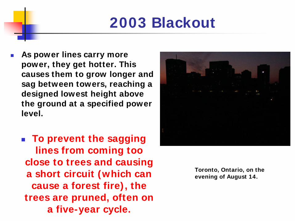
As power lines carry more power, they get hotter. This causes them to grow longer and sag between towers, reaching a designed lowest height above the ground at a specified power level.
To prevent the sagging lines from coming too
close to trees and causing a short circuit (which can cause a forest fire), the
trees are pruned, often on a five-year cycle.
Toronto, Ontario, on the evening of August 14.
2003 Blackout - CauseIn February 2004, the U.S.-Canada Power System Outage Task Force released their final report, placing the main cause of the blackout on FirstEnergy Corporation's failure to trim trees in part of its Ohio service area. The report said that a generating plant in Eastlake, Ohio (a suburb of Cleveland) went offline amid high electrical demand, and that strained high-voltage power lines (located in a distant rural setting) later went out of service when they came in contact with "overgrown trees". The cascading effect that resulted ultimately forced the shutdown of more than 100 power plants.
Cost of Blackout 2003
Anderson Economic Group (AEG) estimates the likely total cost to be between $4.5 and $8.2 billion with a mid-point of $6.4 billion. This includes $4.2 billion in lost income to workers and investors, $15 to $100 million in extra costs to government agencies (e.g., due to overtime and emergency service costs), $1 to $2 billion in costs to the affected utilities, and between $380 and $940 million in costs associated with lost or spoiled commodities.
The blackout contributed to at least eleven (11) fatalities!
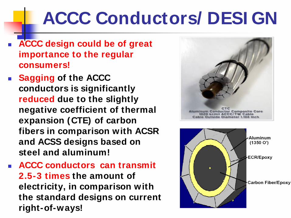
ACCC Conductors/DESIGNACCC design could be of great importance to the regular consumers!Sagging of the ACCC conductors is significantly reduced due to the slightly negative coefficient of thermal expansion (CTE) of carbon fibers in comparison with ACSR and ACSS designs based on steel and aluminum!ACCC conductors can transmit 2.5-3 times the amount of electricity, in comparison with the standard designs on current right-of-ways!
ACCC Conductors/Problems
Extreme environments: aging in air at 200C, ozone exposure, pollution, stress corrosion in nitric acid, large mechanical loads (icing, galloping)Desirable service time – 50 yearsDamaged during manufacturing, transportation, installationGalvanic reaction between aluminum and carbon fibersMechanical failure by fatigue (aeolian vibrations, gallopingOthers (TBD by us)
ACCC Conductors/Excessive Bending
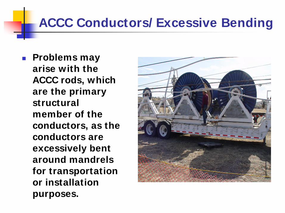
Problems may arise with the ACCC rods, which are the primary structural member of the conductors, as the conductors are excessively bent around mandrels for transportation or installation purposes.
ACCC Conductors/Excessive Bending
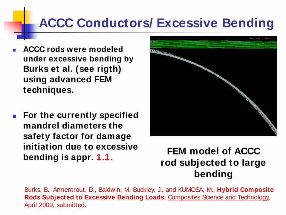
ACCC rods were modeled under excessive bending by Burks et al. (see rigth) using advanced FEM techniques.
For the currently specified mandrel diameters the safety factor for damage initiation due to excessive bending is appr. 1.1.
Burks, B., Armentrout, D., Baldwin, M. Buckley, J., and KUMOSA, M., Hybrid Composite Rods Subjected to Excessive Bending Loads, Composites Science and Technology, April 2009, submitted.
FEM model of ACCC rod subjected to large
bending

ACCC Conductors/Ozone Effect on Polymer Composites
This research showed that ozone could play a very significant role in the degradation of the polymer matrix composites.“FTIR Analysis of the Degradation of Glass Reinforced Polymer Composites Subject to Ozone Exposure” By T. Stephen, M. Moyle, B. Burks, D. Smith, P. Predecki and M. Kumosa, submitted to IEEE Transactions on Dielectrics and Electrical Insulation, May 2009, submitted.
Transmission (FTIR) spectra for E-glass/epoxy for successive periods
of exposure to ozone.
The ratio of the C=O absorbances to the CHn absorbances for three
different E-glass/polymer composites

ACCC Conductors/Technology TransferPublications so far:1. Burks, B., Armentrout, D. and KUMOSA, M., Failure Prediction Analysis of an ACCC Conductor Subjected to Thermal and Mechanical Stresses, IEEE Transactions on Dielectrics and Electrical Insulation, submitted in April 20092. Burks, B., Armentrout, D., Baldwin, M. Buckley, J., and KUMOSA, M., Hybrid Composite Rods Subjected to Excessive Bending Loads, Composites Science and Technology, April 2009, submitted.3. Stephen T. M., Moyle, M., Burks, B., Smith, D. M., Predecki, P. and KUMOSA, M., FTIR Analysis of the Degradation of Glass Reinforced Polymer Composites Subject to Ozone Exposure, IEEE Transactions on Dielectrics and Electrical Insulation, submitted in May 2009
Invited talks:IEEE Power Society Summer Meeting, 29th of August 2009,Calgary:one hour talk by Burks and Kumosa to international designers of transmission lines

Palo Verde Nuclear Generation Station
Palo Verde Nuclear Generating Station is the largest nuclear electric generating site in the United States. Three (3) Combustion Engineering Pressurized Water Reactor units each have an output of ~ 1300 MWe. Each unit has 2 reactor cooling loops, each with a 2 reactor cooling pump and a single steam generator. Arizona Public Service Company is the operator and co-owns the units with utilities in New Mexico, Texas, and California. The Palo Vede site is at Wintersberg, Arizona, 34 miles west of Phoenix. Units 1 and 2 went commercial in 1986 and Unit 3 in 1988.
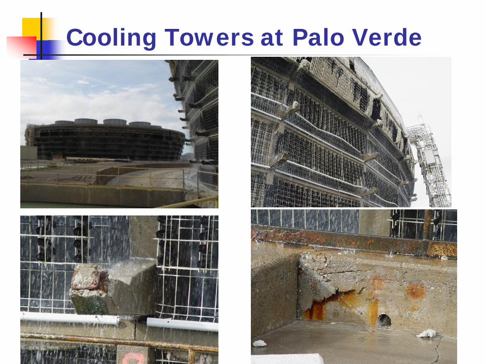
Cooling Towers at Palo Verde
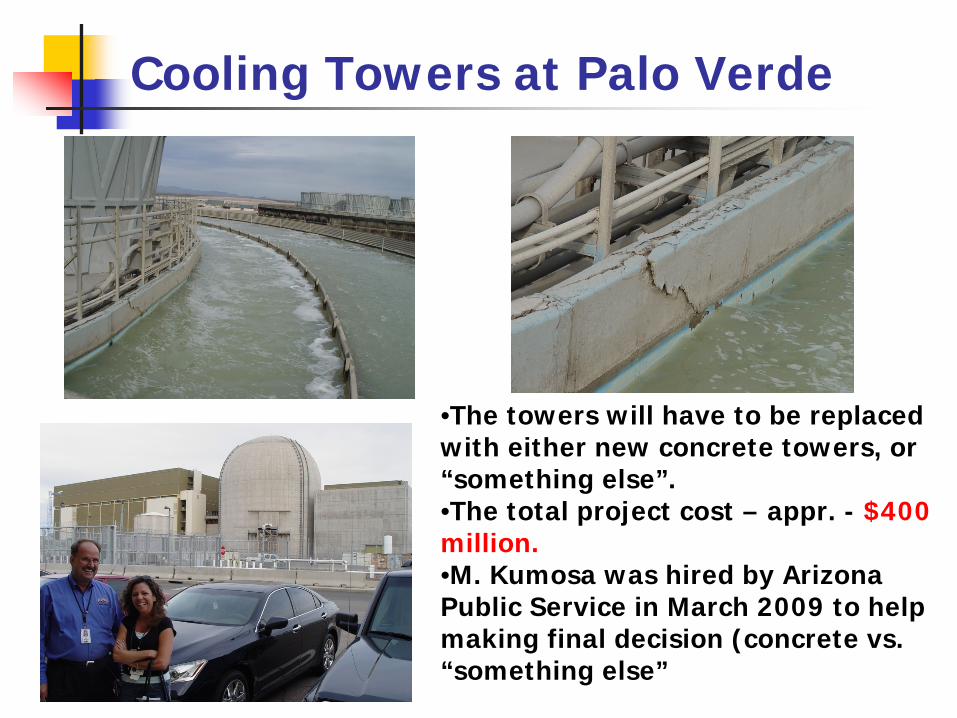
Cooling Towers at Palo Verde
•The towers will have to be replaced with either new concrete towers, or “something else”. •The total project cost – appr. - $400 million. •M. Kumosa was hired by Arizona Public Service in March 2009 to help making final decision (concrete vs. “something else”
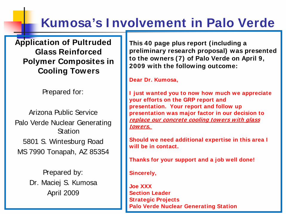
Kumosa’s Involvement in Palo VerdeApplication of Pultruded
Glass Reinforced Polymer Composites in
Cooling Towers
Prepared for:
Arizona Public ServicePalo Verde Nuclear Generating
Station5801 S. Wintesburg Road
MS 7990 Tonapah, AZ 85354
Prepared by:Dr. Maciej S. Kumosa
April 2009
This 40 page plus report (including a preliminary research proposal) was presented to the owners (7) of Palo Verde on April 9, 2009 with the following outcome:
Dear Dr. Kumosa,
I just wanted you to now how much we appreciate your efforts on the GRP report and presentation. Your report and follow up presentation was major factor in our decision to replace our concrete cooling towers with glass towers.
Should we need additional expertise in this area I will be in contact.
Thanks for your support and a job well done!
Sincerely,
Joe XXXSection LeaderStrategic ProjectsPalo Verde Nuclear Generating Station
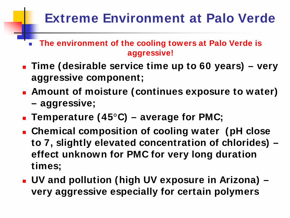
Extreme Environment at Palo Verde
The environment of the cooling towers at Palo Verde is aggressive!
Time (desirable service time up to 60 years) – very aggressive component;Amount of moisture (continues exposure to water) – aggressive;Temperature (45°C) – average for PMC;Chemical composition of cooling water (pH close to 7, slightly elevated concentration of chlorides) –effect unknown for PMC for very long duration times;UV and pollution (high UV exposure in Arizona) –very aggressive especially for certain polymers

Manufacturers of Composite Towers; What do they know?
Manufacturers have recommended to M. Kumosa either E-glass/ isophthalic polyester, E-glass/vinyl ester or E-glass/polyurethane composites (three very different GRP composites with very different properties and durabilities!!!)The manufacturers do not have any truly long-term data regarding the effect of time and moisture on the physical properties of their composites. They only extrapolate the long term behavior of their composites in moisture at elevated temperatures from the short term data assuming that the physical and chemical properties of their composites will not change with time. However, these composite will degrade, the resins will decompose, the glass fiber/polymer interfaces will get damaged with time. Cracks will developed and the moisture absorption characteristics of the composites will change. This will also lead to major reductions of their strength properties
The question is; how soon will these negative effects start drastically affecting the performance of the towers? And this is a truly multi-million dollar question!
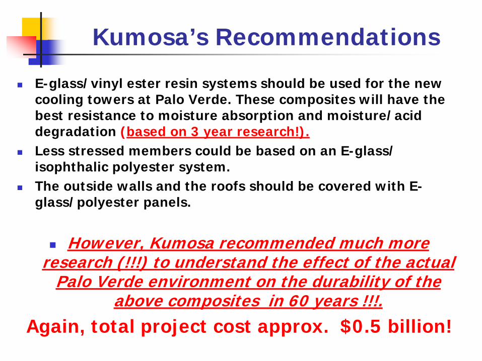
Kumosa’s Recommendations
E-glass/vinyl ester resin systems should be used for the new cooling towers at Palo Verde. These composites will have the best resistance to moisture absorption and moisture/acid degradation (based on 3 year research!).Less stressed members could be based on an E-glass/isophthalic polyester system. The outside walls and the roofs should be covered with E-glass/polyester panels.
However, Kumosa recommended much more research (!!!) to understand the effect of the actual
Palo Verde environment on the durability of the above composites in 60 years !!!.
Again, total project cost approx. $0.5 billion!

GRP Composite Cooling Tower
Glass Reinforced Polymer Cooling Tower at Progress Energy’s Anclote Plant
One composite cooling tower is already standing- built in 2008
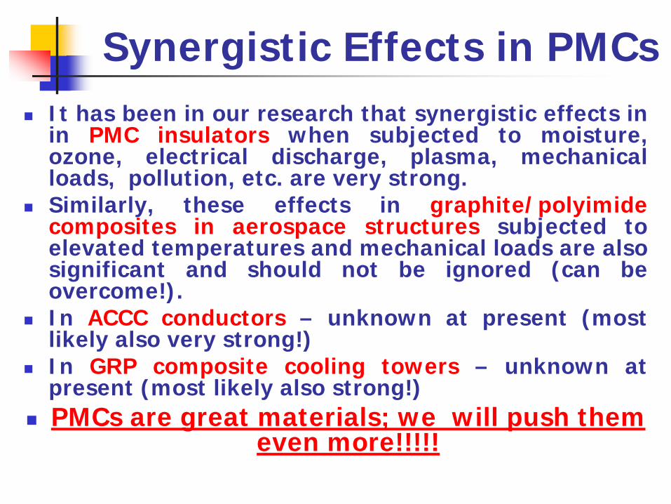
Synergistic Effects in PMCs It has been in our research that synergistic effects inin PMC insulators when subjected to moisture,ozone, electrical discharge, plasma, mechanicalloads, pollution, etc. are very strong.Similarly, these effects in graphite/polyimidecomposites in aerospace structures subjected toelevated temperatures and mechanical loads are alsosignificant and should not be ignored (can beovercome!).In ACCC conductors – unknown at present (mostlikely also very strong!)In GRP composite cooling towers – unknown atpresent (most likely also strong!)PMCs are great materials; we will push them
even more!!!!!