application program description 0701 co weather station 914301€¦ · gamma instabus application...
TRANSCRIPT

GAMMA instabus
Application program description
September 2010
0701 CO Weather Station 914301
Siemens AG 914301, 24 pages Technical manual Industry Sector, Building Technologies Low Voltage Distribution © Siemens AG 2010 Update: http://www.siemens.de/gamma PO Box 10 09 53, D-93009 Regensburg Subject to change without further notice
3.12.5.3.1/1
Verwendung des Applikationsprogramms Product family: Physical Sensors Product type: Weather station w/ integrated sensors Manufacturer: Siemens
Name: Weather station WS1 (GPS) AP 257/32 Order no.: 5WG1 257-3AB32
Content overview
1. Function overview 1 2. Façades 2 2.1. Number of façades .........................................2 2.2. Façade alignment ...........................................2 2.3. Façade inclination ..........................................2 2.4. Blind angles....................................................2 3. Behavior at voltage failure / recovery 3 4. Communication objects 4 5. Parameter windows 8 5.1. Location.........................................................8 5.2. General adjustments.....................................10 5.3. Functions, Objects ........................................10 5.4. Wind speed ..................................................11 5.5. Wind speed limit value x ...............................12 5.6. Brightness ....................................................13 5.7. Brightness limit value x .................................13 5.8. Twilight........................................................14 5.9. Twilight limit value x.....................................15 5.10. Precipitation.................................................16 5.11. Outside temperature ....................................16 5.12. Outside temperature limit value x..................17 5.13. Safety ..........................................................18 5.14. Façade control..............................................19 5.15. Façade x, functions.......................................20 5.16. Façade x, actions ..........................................20 5.17. Logic............................................................23 5.18. AND logic operation x, OR logic operation x ...23
1. Function overview In a compact housing, the AP 257/32 weather station WS1 (GPS) contains all sensors, the evaluating electronic system and the bus coupling unit. It measures wind speed, brightness and temperature, recognizes twilight and precipitation and receives the GPS (Global Position-ing System) radio signal for date and UTC-time (UTC - Universal Time Coordinated). In addition to date and time, all measured values can be transmitted on the bus in EIS5 (DPT 9) format and re-spectively monitored on up to 3 limit values. Limit val-ues can be selected as parameters or as communication objects. Using the “Safety” parameter window, in addition to wind alarm, frost alarm and precipitation alarm, a total of up to 8 alarm or failure messages can be combined via a logical OR-function to a “Safety” communication object, which in the case of alarm results in the sun pro-tection moving into its safety position. In addition 4 AND-gates and 4 OR-gates with 4 inputs each are available for further logic operations. The weather station WS1 does not only render possible a simple solar protection control in which the solar pro-tection is activated or deactivated, depending on whether the sun is shining or not. It can also activate a sun protection control for up to 4 façades under consid-eration of their alignment (direction of the compass), inclination and blind angles. In this case, the sun protec-tion for a façade is automatically activated only when the sun is shining on the respective façade and deacti-vated as soon as this is no longer possible or the sun is no longer shining. This weather station may even be used in places with-out GPS radio reception. In this case date and time have to be received e.g. via the internet and have to be trans-mitted via the bus to the weather station. The use of the ETS3 Engineering Tool Software is rec-ommended, since it renders possible the best graphic display of the weather station setting menus.

GAMMA instabus
Application program description
September 2010
0701 CO Weather Station 914301
Technical manual 914301, 24 pages Siemens AG Industry Sector, Building Technologies Update: http://www.siemens.de/gamma © Siemens AG 2010 Low Voltage Distribution Subject to change without further notice PO Box 10 09 53, D-93009 Regensburg
3.12.5.3.1/2
2. Façades
2.1. Number of façades
For façade control the respective alignment of a façade based on the north-south axis and its respective inclina-tion based on the perpendicular on the ground have to be considered. Furthermore, it should be taken into ac-count whether the sun can shine directly from the side and vertically from above onto the façade or whether it can only shine on the façade from a specific angle that is larger than a blind angle predetermined by a wall or roof projection. Most buildings have 4 façades (see Fig. 1). Since only rarely a façade is aligned exactly northwards, it is rec-ommended in principle for the sun protection to be con-trolled separately for each façade. If a building has more than 4 façades, the use of an ad-ditional weather station WS1 (GPS) AP 257/32 or of the weather station (GPS) AP 257/22 which can control up to 8 façades, is recommended. In the case of several buildings, the use of one weather station per building is recommended in principle, since different wind speeds can arise, depending on the loca-tion of the buildings with respect to one another. 2.2. Façade alignment
The façade alignment corresponds to the angle between the north-south axis and the perpendicular on the fa-çade (see Fig. 1). The angle α (in the range from 0° to 359°) is hereby measured in clockwise direction (north corresponds to 0°, east 90°, south 180° and west 270°).
Figure 1 Façade alignment 2.3. Façade inclination
If a façade surface is not aligned vertically, this must be taken into account. A forward inclination of the façade
is counted as a positive angle, a backward inclination as a negative angle (see Fig. 2).
Figure 2 Façade inclination The sun protection of windows installed in a sloping roof area can thus also be controlled according to the current position of the sun. If a façade is not a flat surface, but curved or bent, it must be subdivided into several segments, which must be controlled separately. 2.4. Blind angles If the sun cannot shine directly from the side and verti-cally from above onto the façade because this is ob-structed by a wall or roof projection, this can be taken into account with the façade control. Fig. 3 shows how a horizontal blind angle α is meas-ured. With the façade control it is presumed that the horizontal blind angle is the same size on both façade sides. Fig. 4 shows how a vertical blind angle is meas-ured.
Figure 3 Horizontal blind angle

GAMMA instabus
Application program description
September 2010
0701 CO Weather Station 914301
Siemens AG 914301, 24 pages Technical manual Industry Sector, Building Technologies Low Voltage Distribution © Siemens AG 2010 Update: http://www.siemens.de/gamma PO Box 10 09 53, D-93009 Regensburg Subject to change without further notice
3.12.5.3.1/3
Figure 4 Vertical blind angle
3. Behavior at voltage failure / recovery In the event of failure of the supply voltage the weather station WS1 does not store any data. Upon recovery of the supply voltage, it records the current sensor data and transmits them. The weather station then waits for date and time to be updated. As soon as these have been received, without taking into account parameter-ized waiting times, the actions respectively after the end of the delay period 2 are sent immediately (i.e., with those façades on which the sun is not shining according to the current values of date, time and brightness, at least "Façade x, Sunshine = OFF" is sent and for the oth-ers "Façade x, Sunshine = ON"). A bus voltage failure is recognized by the weather sta-tion WS1. Data that change after the bus voltage failure are stored and transmitted after the bus voltage recov-ery.
GAMMA instabus
Application program description
September 2010
0701 CO Weather Station 914301
Technical manual 914301, 24 pages Siemens AG Industry Sector, Building Technologies Update: http://www.siemens.de/gamma © Siemens AG 2010 Low Voltage Distribution Subject to change without further notice PO Box 10 09 53, D-93009 Regensburg
3.12.5.3.1/4
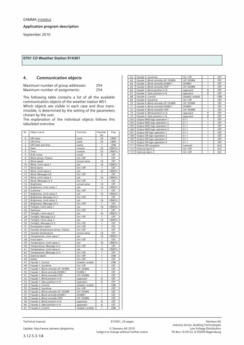
4. Communication objects
Maximum number of group addresses: 254 Maximum number of assignments: 254
The following table contains a list of all the available communication objects of the weather station WS1. Which objects are visible in each case and thus trans-missible, is determined by the setting of the parameters chosen by the user. The explanation of the individual objects follows this tabulated overview. Nr. Object name Function Number
Bit Flag
0 GPS date send 24 CRWT 1 GPS time send 24 CRWT 2 GPS date and time query 1 CRW 3 Date receive 24 CRWTU 4 Time receive 24 CRWTU 5 8-bit scene recall 8 CRT 6 Wind sensor, Failure On / Off 1 CRT 7 Wind speed actual value 16 CRT
10 Wind, Limit value 1 set 16 CRWTU 11 Wind alarm On / Off 1 CRT 12 Wind, Limit value 2 set 16 CRWTU 13 Wind, Message LV2 On / Off 1 CRT 14 Wind, Limit value 3 set 16 CRWTU 15 Wind, Message LV 3 On / Off 1 CRT 16 Brightness actual value 16 CRT 19 Brightness, Limit value 1 set 16 CRWTU 20 Sunshine On / Off 1 CRT 21 Brightness, Limit value 2 set 16 CRWTU 22 Brightness, Message LV 2 On / Off 1 CRT 23 Brightness, Limit value 3 set 16 CRWTU 24 Brightness, Message LV 3 On / Off 1 CRT 25 Twilight, Limit value 1 set 16 CRWTU 26 Darkness On / Off 1 CRT 27 Twilight, Limit value 2 set 16 CRWTU 28 Twilight, Message LV 2 On / Off 1 CRT 29 Twilight, Limit value 3 set 16 CRWTU 30 Twilight, Message LV 3 On / Off 1 CRT 31 Precipitation alarm On / Off 1 CRT 32 Outside temperature sensor, Failure On / Off 1 CRT 33 Outside temperature actual value 16 CRT 37 Temperature, Limit value 1 set 16 CRWTU 38 Frost alarm On / Off 1 CRT 39 Temperature, Limit value 2 set 16 CRWTU 40 Temperature, Message LV 2 On / Off 1 CRT 41 Temperature, Limit value 3 set 16 CRWTU 42 Temperature, Message LV 3 On / Off 1 CRT 43 External alarm On / Off 1 CRW 44 Safety On / Off 1 CRT 47 Façade 1, Control disable / enable 1 CRW 48 Façade 1, Sunshine On / Off 1 CRT 49 Façade 1, Blind centrally UP / DOWN UP / DOWN 1 CRT 50 Façade 1, Blind centrally DOWN 1 DOWN 1 1 CRT 51 Façade 1, Blind centrally STEP UP / DOWN 1 CRT 52 Façade 1, Blind position in % approach 8 CRT 53 Façade 1, Slats position in % approach 8 CRT 54 Façade 2, Control disable / enable 1 CRW 55 Façade 2, Sunshine On / Off 1 CRT 56 Façade 2, Blind centrally UP / DOWN UP / DOWN 1 CRT 57 Façade 2, Blind centrally DOWN 1 DOWN1 1 CRT 58 Façade 2, Blind centrally STEP UP / DOWN 1 CRT 59 Façade 2, Blind position in % approach 8 CRT 60 Façade 2, Slats position in % approach 8 CRT 61 Façade 3, Control disable / enable 1 CRW
62 Façade 3, Sunshine On / Off 1 CRT 63 Façade 3, Blind centrally UP / DOWN UP / DOWN 1 CRT 64 Façade 3, Blind centrally DOWN 1 DOWN1 1 CRT 65 Façade 3, Blind centrally STEP UP / DOWN 1 CRT 66 Façade 3, Blind position in % approach 8 CRT 67 Façade 3, Slats position in % approach 8 CRT 68 Façade 4, Control disable / enable 1 CRW 69 Façade 4, Sunshine On / Off 1 CRT 70 Façade 4, Blind centrally UP / DOWN UP / DOWN 1 CRT 71 Façade 4, Blind centrally DOWN 1 DOWN1 1 CRT 72 Façade 4, Blind centrally STEP UP / DOWN 1 CRT 73 Façade 4, Blind position in % approach 8 CRT 74 Façade 4, Slats position in % approach 8 CRT
103 Output AND logic operation 1 0 / 1 1 CRT 104 Output AND logic operation 2 0 / 1 1 CRT 105 Output AND logic operation 3 0 / 1 1 CRT 106 Output AND logic operation 4 0 / 1 1 CRT 107 Output OR logic operation 1 0 / 1 1 CRT 108 Output OR logic operation 2 0 / 1 1 CRT 109 Output OR logic operation 3 0 / 1 1 CRT 110 Output OR logic operation 4 0 / 1 1 CRT 111 Failure GPS reception transmit 1 KLÜ 112 External alarm 2 On / Off 1 KLS 113 External alarm 3 On / Off 1 KLS

GAMMA instabus
Application program description
September 2010
0701 CO Weather Station 914301
Siemens AG 914301, 24 pages Technical manual Industry Sector, Building Technologies Low Voltage Distribution © Siemens AG 2010 Update: http://www.siemens.de/gamma PO Box 10 09 53, D-93009 Regensburg Subject to change without further notice
3.12.5.3.1/5
Obj Objektname Funktion Typ Flag
0 GPS date Send 3 Byte CRWT This object is visible only if in the "Functions, Objects" parame-ter window the parameter "Date, Time" is set at "receive via GPS." The date received by the GPS receiver integrated into the weather station is transmitted on the bus via this object. Note: After mains recovery / restart it can take several minutes until the date and time are synchronized via the GPS receiver. If date and time are requested at the weather station during this time, it sends telegrams with the content "0." 1 GPS time Send 3 Byte CRWT This object is visible only if in the "Functions, Objects" parame-ter window the parameter "Date, Time" is set at "receive via GPS". The time received by the GPS receiver integrated into the weather station is sent on the bus via this object. Note: After mains recovery / restart it can take several minutes until date and time are synchronized via the DCF77 receiver. If date and time are requested at the weather station during this time, it sends telegrams with the content "0." 2 GPS date and time Query 1 Bit CRW This object is visible only if in the "Functions, Objects" parame-ter window the parameter "Date, Time" is set at "receive via GPS". The transmission of date and time can be requested at the weather station at any time using this object. The telegram content (log. 0 or 1) is hereby irrelevant. 3 Date Receive 3 Byte CRWTU This object is visible only if in the "Functions, Objects" parame-ter window the parameter “Date, Time“ is set at "Receive via the bus". If a GPS reception is not possible at the installation site of the weather station, using this object the current date (which is provided, e.g., by a Master clock or over the Internet) can be sent to the weather station to synchronize its software clock. A synchronization after bus or mains failure can take up to 30 s. 4 Time Receive 3 Byte CRWTU This object is visible only if in the "Functions, Objects" parame-ter window the parameter "Date, Time" is set at "Receive via the bus" If a GPS reception is not possible at the installation site of the weather station, using this object the current time (which is provided, e.g., by a Master clock or over the Internet) can be sent to the weather station to synchronize its software clock. The synchronization after bus or mains failure can take up to 30 s. Note The time telegram must contain the information of the current day of the week, as otherwise it will not be accepted.
Obj Objektname Funktion Typ Flag
5 8-bit scene Recall 1 Byte CRT Using this object the 8-bit scene with the number x can be re-called. Bit 0...5 hereby contain the scene number. To recall a scene, Bit 7 must be set at log. 0. Bit 6 is currently of no sig-nificance and must be set at log. 0. 6 Wind sensor, Fail-
ure On / Off 1 Bit CRT
This object is visible only if in the "Functions, Objects" parame-ter window the parameter "Wind speed" is set at "include". A failure of the wind sensor recognized by the weather station is reported via this object. 7 Wind speed Actual va-
lue 2 Byte CRT
This object is visible only if in the "Functions, Objects" parame-ter window the parameter "Wind speed" is set to "include". This object is used to transmit the current wind speed as a 16-bit floating point number, optionally with the dimension m/s or km/h. 10 (12, 14)
Wind, Limit value 1 (2, 3)
Set 2 Byte CRWTU
These objects are visible only if in the "Wind speed" parameter window the relevant parameter “Application of limit value x” is set at "Yes". Using these objects the respectively associated limit value can be set via the bus to a new value. 11 Wind alarm On / Off 1 Bit CRT This object is visible only if in the "Wind speed" parameter win-dow the relevant parameter "Application of limit value x" is set at “Yes”. This object is used to report "Wind Alarm = On" as soon as the current wind speed exceeds the limit value 1 and "Wind Alarm = Off" as soon as the current wind speed reaches or falls below the limit value 1 minus hysteresis. 13 (15) Wind, Message LV 2
(3) On / Off 1 Bit CRT
These objects are visible only if in the "Wind speed" parameter window the relevant parameter "Application of limit value 2 (3) " is set at “Yes”. These objects are used to report that the current wind speed has exceeded limit value 2 (or 3) or that the wind speed is again in the permissible range. 16 Brightness Actual va-
lue 2 Byte CRT
This object is visible only if in the "Functions, Objects" parame-ter window the parameter “Brightness“ is set at "include" and in the parameter window “Brightness” the parameter “Send metered value” is not set to “No”. Using this object the current brightness metered value is transmitted as a 16-bit floating-point number with the dimen-sion Lux.

GAMMA instabus
Application program description
September 2010
0701 CO Weather Station 914301
Technical manual 914301, 24 pages Siemens AG Industry Sector, Building Technologies Update: http://www.siemens.de/gamma © Siemens AG 2010 Low Voltage Distribution Subject to change without further notice PO Box 10 09 53, D-93009 Regensburg
3.12.5.3.1/6
Obj Objektname Funktion Typ Flag
19 (21, 23)
Brightness, Limit value 1 (2, 3)
Set 2 Byte CRWTU
These objects are visible only if in the "Brightness" parameter window the relevant parameter "Application of limit value x" is set at "Yes” and in the parameter window “Brightness, limit value x” the parameter “Limit value adjustment via” is set to “communication object”. Using these objects the respectively associated limit value can be set to a new value via the bus. 20 Sunshine On / Off 1 Bit CRT This object is visible only if in the "Brightness" parameter win-dow the parameter "Application of limit value 1" is set at "Yes". This object is used to report "Sunshine = On" as soon as the current brightness metered value exceeds the limit value 1 and "Sunshine = Off" as soon as the current brightness me-tered value reaches or falls below the limit value minus hys-teresis. 22 (24) Brightness, Mes-
sage LV 2 (3) On / Off 1 Bit CRT
These objects are visible only if in the “Brightness“ parameter window the relevant parameter “Application of limit value 2 (3)“ is set at “Yes”. These objects are used to report that the current brightness metered value has exceeded the limit value 2 (or 3) or that the brightness is again in the permissible range. 25 (27, 29)
Twilight, Limit value 1 (2, 3)
Set 2 Byte CRWTU
These objects are visible only if in the “Twilight“ parameter window the relevant parameter “Application of limit value x“ is set at “Yes” and in the parameter window “Brightness, limit value x” the parameter “Limit value adjustment via” is set to “communication object”. These objects can be used to set the respectively associated limit value to a new value via the bus. 26 Darkness On / Off 1 Bit CRT This object is visible only if in the "Twilight" parameter window the parameter "Application of limit value 1" is set at "Yes”. This object is used to report "Darkness = On" as soon as the current brightness metered value falls below the twilight limit value 1 and "Darkness = Off" as soon as the current brightness metered value reaches or exceeds the limit value 1 plus hys-teresis.
Obj Objektname Funktion Typ Flag
28 (30) Twilight, Message LV 2 (3)
On / Off 1 Bit CRT
These objects are visible only if in the "Twilight" parameter window the relevant parameter "Application of limit value 2 (3) " is set at "Yes”. These objects are used to report that the current brightness metered value has fallen below the limit value 2 (or 3) or that the brightness is again in the permissible range. 31 Precipitation alarm On / Off 1 Bit CRT This object is visible only if in the "Functions, objects" parame-ter window the parameter "Precipitation alarm" is set at "include." Using this object "Precipitation Alarm = On" is reported as soon as precipitation is detected and "Precipitation Alarm = Off" when it is no longer raining or snowing. 32 Outside tempera-
ture sensor, Failure On / Off 1 Bit CRT
This object is visible only if in the "Functions, objects" parame-ter window the parameter "Outside temperature" is set at "include". A failure in the temperature sensor recognized by the weather station is reported via this object. 33 Outside tempera-
ture Actual va-lue
2 Byte CRT
This object is visible only if in the “Functions, objects” parame-ter window the parameter “Outside temperature“ is set at "include" and in the parameter window “Outside temperature” the parameter “Send metered value” is not set to “No”. Using this object the current outside temperature is transmit-ted as 16-bit floating point number, optionally with the di-mension °C or °F. 37 (39, 41)
Temperature, Limit value 1 (2, 3)
Set 2 Byte CRWTU
These objects are visible only if in the "Outside temperature" parameter window the relevant parameter "Application of limit value x“ is set at “Yes”. Using these objects the respectively associated limit value can be set to a new value via the bus. 38 Frost alarm On / Off 1 Bit CRT This object is visible only if in the "Outside temperature" pa-rameter window the parameter “Application of limit value 1“ is set at “Yes”. This object is used to report "Frost-Alarm = On" as soon as the current temperature metered value falls below the limit value 1 and "Frost-Alarm = Off, " as soon as the current temperature metered value reaches or exceeds the limit value 1 plus hys-teresis.

GAMMA instabus
Application program description
September 2010
0701 CO Weather Station 914301
Siemens AG 914301, 24 pages Technical manual Industry Sector, Building Technologies Low Voltage Distribution © Siemens AG 2010 Update: http://www.siemens.de/gamma PO Box 10 09 53, D-93009 Regensburg Subject to change without further notice
3.12.5.3.1/7
Obj Objektname Funktion Typ Flag
40 (42) Temperature, Mes-sage LV 2 (3)
On / Off 1 Bit CRT
These objects are visible only if in the "Outside temperature" parameter window the relevant parameter "Application of limit value 2 (3)" is set at “Yes”. These objects are used to report that the current temperature metered value has fallen below (or exceeded) limit value 2 (or 3) and that the outside temperature is once again in the re-spectively permissible range. 43 External alarm On / Off 1 Bit CRW This object is visible only if in the "Functions, Objects" parame-ter window the parameter "Safety" is set at “Yes”. Using this object, e.g., a wind alarm message to be addition-ally applied can be transmitted to the weather station by one or more wind sensors. Note: External alarm inputs are not monitored i.e. failure of an alarm sensor cannot be detected. 44 Safety On / Off 1 Bit CRT This object is visible only if in the "Functions, Objects" parame-ter window the parameter "Safety" is set at “Yes”. This object is used to report "Safety = On" when one or more of the alarm messages combined via an OR-function is set at log. 1 and "Safety = Off " when none of the alarm messages is set at log. 1. 47 (54, 61, 68)
Façade 1 (2, 3, 4), Control
Disable = 1 / enable = 0
1 Bit CRW
These objects are visible only if in the “Façade control” pa-rameter window the parameter "Façade x" is respectively set at “to be used”. Using these objects the shade control for each façade can be disabled (object value=1) and enabled (object value=0) sepa-rately (e.g. via a time switch program). Note: Disabling / enabling the façade control may never be used to prevent a movement of the sun protection. The “movement blockade” object of the sun protection actua-tors must be used for this! Disabling / enabling the façade control can be used, e.g., to ac-tivate the sun protection in summer with enabled sun protec-tion control as soon as the sun shines on the façade. In the winter, on the other hand, the sun protection control can be enabled, e.g., only during the core working hours, in order to thus make it possible for the winter sun to heat the rooms as long as these are not used.
Obj Objektname Funktion Typ Flag
48 (55, 62, 69)
Façade 1 (2, 3, 4), Sunshine
On / Off 1 Bit CRT
These objects are visible only if in the "Façade control" pa-rameter window the parameter "Façade x" is respectively set to “to be used”. Using these objects "Façade x, Sunshine = On" is transmitted when the sun is shining and the rays of sun could also fall on the respective façade. "Façade x, sunshine = Off" is transmitted when the sun is no longer shining or the rays of sun can no longer fall on the respective façade. 49 (56, 63, 70)
Façade 1 (2, 3, 4), Blind centrally UP / DOWN
UP / Down 1 Bit CT
These objects are visible only if in the "Façade x, Actions" pa-rameter window the parameter "Action 2“ is set in each case to "Central command DOWN“ or to "Central command UP”. These objects can be used to move the sun protection for each façade into the upper or lower end position. 50 (57, 64, 71)
Façade 1 (2, 3, 4), Blind centrally DOWN 1
Down 1 1 Bit CT
These objects are visible only if in the "Façade x, Actions" pa-rameter window the parameter "Action 2" is set at "Central Command DOWN 1”. Using these objects the sun protection, with drives with 3 limit switches, for each façade can be moved to the lower DOWN 1 end position, in which it then remains with completely opened (i.e., horizontal) slats. 51 (58, 65, 72)
Façade 1 (2, 3, 4), Blind centrally STEP
Up / Down 1 Bit CT
These objects are visible only if in the "Façade x, Actions" pa-rameter window the parameter "If brightness, Message LV = Off, Action" is set at "Blind stepwise UP”. If the sun is no longer shining on a façade, with this as the first action the sun protection or its slats can be opened by the set number of steps. 52 (59, 66, 73)
Façade 1 (2, 3, 4), Blind position in %
Approach 1 Byte CT
These objects are visible only if in the parameter window "Fa-çade x, Actions" one of the parameters is set at "Blind position in %." Using this object the movement of the sun blind into the re-spectively parameterized position is started with the respective façade. 53 (60, 67, 74)
Façade 1 (2, 3, 4), Slats position in %
Approach 1 Byte CT
These objects are visible only if in the “Façade x, Actions” pa-rameter window one of the parameters is set at “Slats position in %.” Using this object the adjustment of the slats into the respec-tively parameterized position is started with the respective fa-çade.
GAMMA instabus
Application program description
September 2010
0701 CO Weather Station 914301
Technical manual 914301, 24 pages Siemens AG Industry Sector, Building Technologies Update: http://www.siemens.de/gamma © Siemens AG 2010 Low Voltage Distribution Subject to change without further notice PO Box 10 09 53, D-93009 Regensburg
3.12.5.3.1/8
Obj Objektname Funktion Typ Flag
103 (104, 105, 106)
Output AND logic operation 1 (2….4)
0 / 1 1 Bit CRT
These objects are visible only if in the “Logic“ parameter win-dow the parameter “AND logic operation x“ is respectively set at “active.“ Using these objects respectively "Output AND logic operation x = On“ is sent when the result of the AND combination is a log. 1, and "Output AND logic operation x = Off" is sent when the result of the AND combination is a log. 0. 107 (108, 109, 110)
Output OR logic operation 1 (2….4)
0 / 1 1 Bit CRT
These objects are visible only if in the “Logic“ parameter win-dow the parameter “OR logic operation x“ is respectively set to “active.“ Using these objects respectively "Output OR logic operation x = On" is sent when the result of the OR combination is a log. 1, and "Output OR logic operation x = Off“ is sent when the re-sult of the OR combination is log. 0. 111 Failure GPS
reception transmit 1 Bit CRT
Via this object „Failure GPS reception = On“ is transmitted, when reception of date and time via the GPS receiver is not possible and „Failure GPS reception = Off“ is transmitted, when GPS reception is perfect. The current status of this object is transmitted on each recov-ery of bus and supply voltage. 112 (113)
External Alarm 2 (3) On / Off 1 Bit CRW
These objects are only visible if in the parameter window „Sa-fety“ the parameter „Add object External alarm“ is set to a value greater than 1. Via these objects further alarms e.g. from additional wind sen-sors (one per façade) additionally to be taken into account can be transmitted to the weather station.
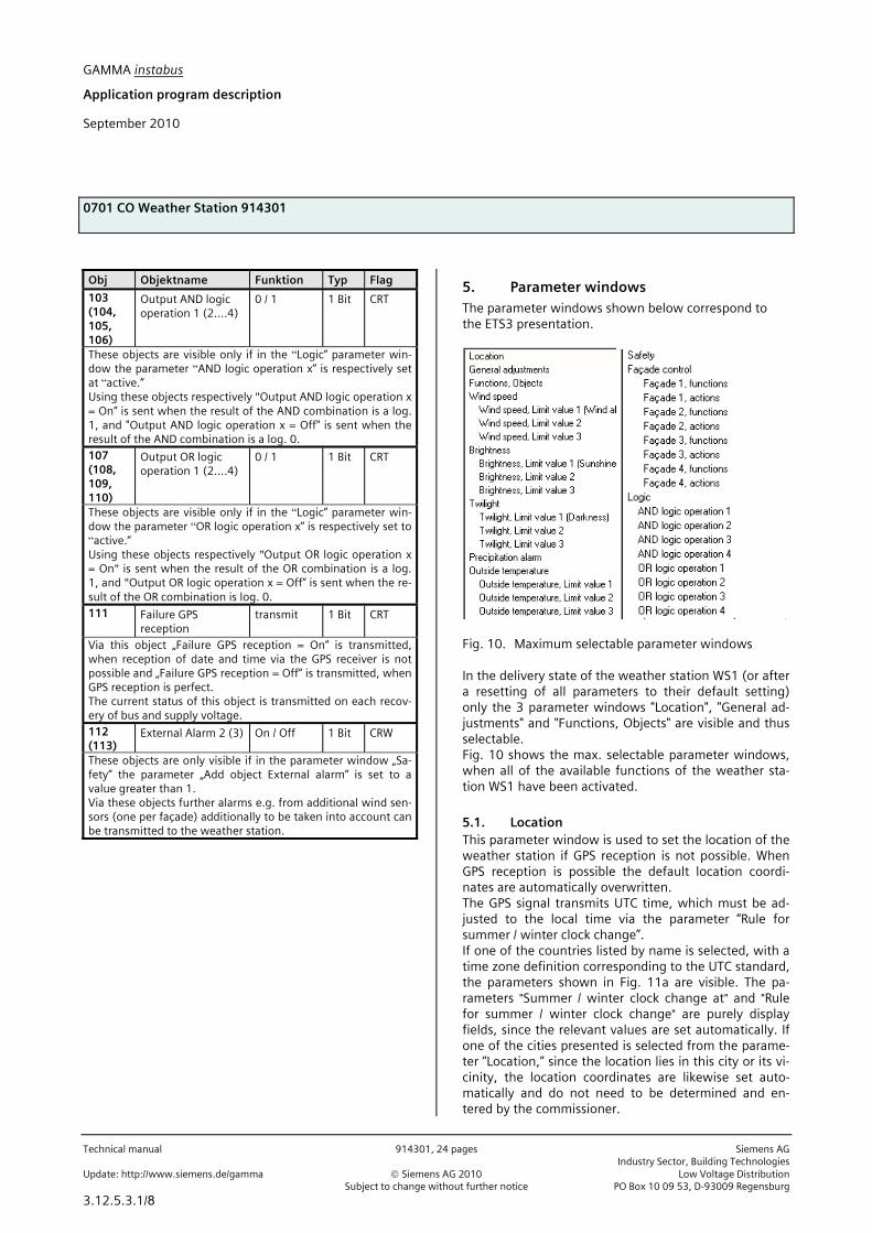
5. Parameter windows The parameter windows shown below correspond to the ETS3 presentation.
Fig. 10. Maximum selectable parameter windows In the delivery state of the weather station WS1 (or after a resetting of all parameters to their default setting) only the 3 parameter windows "Location", "General ad-justments" and "Functions, Objects" are visible and thus selectable. Fig. 10 shows the max. selectable parameter windows, when all of the available functions of the weather sta-tion WS1 have been activated.
5.1. Location This parameter window is used to set the location of the weather station if GPS reception is not possible. When GPS reception is possible the default location coordi-nates are automatically overwritten. The GPS signal transmits UTC time, which must be ad-justed to the local time via the parameter “Rule for summer / winter clock change”. If one of the countries listed by name is selected, with a time zone definition corresponding to the UTC standard, the parameters shown in Fig. 11a are visible. The pa-rameters "Summer / winter clock change at" and "Rule for summer / winter clock change" are purely display fields, since the relevant values are set automatically. If one of the cities presented is selected from the parame-ter “Location,” since the location lies in this city or its vi-cinity, the location coordinates are likewise set auto-matically and do not need to be determined and en-tered by the commissioner.

GAMMA instabus
Application program description
September 2010
0701 CO Weather Station 914301
Siemens AG 914301, 24 pages Technical manual Industry Sector, Building Technologies Low Voltage Distribution © Siemens AG 2010 Update: http://www.siemens.de/gamma PO Box 10 09 53, D-93009 Regensburg Subject to change without further notice
3.12.5.3.1/9
Fig. 11a. Location parameters with selectable country
and selectable city If the country in which the weather station has been in-stalled is not included in the selection of countries, the parameters shown in Fig. 11b are visible. Both the "Rule for summer / winter clock change" and the location co-ordinates must then be entered.
Fig. 11b. Location parameters when the country is not
selectable Note: The setting possibilities in bold below correspond
to the factory default setting of the parame-ters.
Parameter Settings
Country Germany; Austria; Switzer-land; France; Spain; Italy; UK; Netherlands; …. Other countries
This parameter is used to select the country in which the weather station has been installed. The subsequent parame-ters are adjusted depending on the country selected.
Definition of time zone ac-cording to
Standard; specific
This parameter is used to set whether the summer / winter clock change of the selected country corresponds to the local standard or deviates from it (is specific) and therefore has to be set separately.
Summer / winter clock change at
ST: Sun. after March 25th WT: Sun. after Oct 25th
This is purely a display field, which is visible only if the previ-
ous parameter "Definition of time zone according to" is set at "Standard". This shows that the clock change to summer time occurs on the 1st Sunday after March 25 and the clock change to winter time on the 1st Sunday after October 25.
Rule for summer / winter clock change
03257:0200+0100/10257:0200UTC+0100
This is purely a display field if the parameter "Definition of time zone according to” is set at "Standard" and an input field, if it is set at "specific" or if the parameter "Country" is set at "Other countries". In this case date and time must be entered for the respective clock change and the respective time differ-ence, as explained below:
The information up to the slash apply to changing the clock to summer time: "03257" stands for the month (03=March), the date (25) and the day of the week (7=Sunday) and "0200" for the time of the change, “+0100” indicates the number of hours and minutes (1 hour, 0 minutes), by which the previ-ously current winter time is adjusted and “+” the direction of the clock change (+ = set forward). The data after the slash apply to the change to winter time: "10257" stands for the month (10=October), the date (25) and the day of the week (7=Sunday) and “0200” for the time of the switch, and "UTC+0100" indicates the standard time in winter according to the relevant time zone (for Germany, e.g., equal to UTC + 1:00 hour).
Note: The data in this field are taken into account for the fa-çade control. Incorrect data lead to an incorrect façade con-trol.
Location Stuttgart; ... other city
This parameter is visible only if a country has been selected, for which one or more locations are offered for selection.
If this parameter is set to selectable locations, the relevant longitude and latitude data are automatically adjusted.
If none of these locations is relevant and this parameter is therefore set at "other city", the following 4 parameters for en-tering longitude and latitude information are added.
East. longitude [degree, -180 ...+180]
0
This parameter is used to set the degrees to the eastern longi-tude.
East. longitude [minutes, -59...+59]
0
This parameter is used to set the minutes to the eastern longi-tude.
North. latitude [degree, -90 ...+90]
0
This parameter is used to set the degrees to the northern lati-tude.
north. latitude [minutes, -59...+59]
0
This parameter is used to set the minutes to the northern lati-tude.

GAMMA instabus
Application program description
September 2010
0701 CO Weather Station 914301
Technical manual 914301, 24 pages Siemens AG Industry Sector, Building Technologies Update: http://www.siemens.de/gamma © Siemens AG 2010 Low Voltage Distribution Subject to change without further notice PO Box 10 09 53, D-93009 Regensburg
3.12.5.3.1/10
5.2. General adjustments This parameter window is used to set the cycle times for the cyclic transmission of metered values und logic ob-jects, the transmission delay time after bus and mains voltage recovery and the max. telegram rate.
Parameter Settings
Cycle time for cyclic trans-mission of metered values
5 s; 10 s; 30 s; 1 min; 2 min; 5 min; 10 min; 20 min; 30 min; 45 min; 1 h
This parameter is used to set the joint cycle time for cyclic transmission of date and time and for all metered values with cyclic transmission.
Cycle time for cyclic trans-mission of logic objects
5 s; 10 s; 30 s; 1 min; 2 min; 5 min; 10 min; 20 min; 30 min; 45 min; 1 h
This parameter is used to set the joint cycle time for all logic objects with cyclic transmission.
Transmission delay time af-ter bus and mains voltage recovery [in s]
1...10; 5
This parameter is used to set the delay time that must elapse following the bus or mains voltage recovery before the weather station may again transmit telegrams on the bus.
Max. telegram rate [tele-grams per second]
1...10; 5
This parameter is used to set the maximum number of tele-grams the weather station may send on the bus within one second.
5.3. Functions, Objects This parameter window is used to activate the desired functions of the weather station WS1. These include re-ceiving and optionally transmitting date and time, re-cording, monitoring and transmitting wind speed, brightness, twilight, precipitation and outside tempera-ture, the logic combination of several objects to the “Safety” object, the shading control for up to 4 façades, depending on the geographic position of the location and the position of the sun, as well as the logic combi-nation of objects of the weather station WS1 by up to 4 AND gates and up to 4 OR gates with up to 4 inputs each.
Note: The "Twilight" function is available only when the “Brightness“ function is set at "include."
The following figure shows the "Functions, Objects" pa-rameter window when all of the functions have been activated.
Parameter Settings
Date, time receive via GPS; receive via bus
This parameter is used to set whether the weather station should receive the date and time information required via the radio receiver for the time signals of the GPS receiver integrated in the weather station or whether it should receive them via the bus.
Note: If GPS reception is not possible at the location of the weather station, the indicator LED for the reception of the GPS signal (see Operation and Installation instructions) does not flash regularly once a second. In this case this parameter must be set at “receive via bus“ and it must be ensured that a master clock connected to the bus cyclically transmits date and time. Once a time signal was received the LED for the GPS signal flashes always and regularly. If the GPS radio reception is tem-porarily disturbed, date and time will be updated during this time by the software of the weather station (max. divergence 5 s per day).
Send date / time cyclically No; Yes
This parameter is visible only if the parameter “Date, time” is set to “receive via GPS”.
This parameter is used to set whether the weather station serves as a master clock and should transmit the received date and time information cyclically via the bus. If cyclic transmission is activated, this occurs with the same cycle time with which me-tered values are also transmitted cyclically (see parameter win-dow “General Settings”).

GAMMA instabus
Application program description
September 2010
0701 CO Weather Station 914301
Siemens AG 914301, 24 pages Technical manual Industry Sector, Building Technologies Low Voltage Distribution © Siemens AG 2010 Update: http://www.siemens.de/gamma PO Box 10 09 53, D-93009 Regensburg Subject to change without further notice
3.12.5.3.1/11
Parameter Settings
Send GPS date and time upon request
at once; at start of a new minute
This parameter is visible only if the parameter “Date, time” is set to “receive via GPS”.
This parameter is used to set whether the weather station, after request of date and time through another bus device, transmits this information immediately or if necessary with a delay only after a new minute has started, so that the requesting bus de-vice can also be exactly synchronized with this value.
Failure GPS reception do not transmit; transmit on change; transmit on change and cycli-cally
This parameter determines when the object “Failure GPS recep-tion“ is transmitted. If cyclical transmission is selected then it is transmitted with the same cycle time used for measured values (see parameter window “General adjustments”.
Wind speed exclude; include
This parameter is used to set whether the weather station should measure and monitor the wind speed. If this parameter is set to “include” the selection option of the “Wind speed” function is added on the left side of the parameter-window of the ETS3.
Brightness exclude; include
This parameter is used to set whether the weather station should measure and monitor brightness. If this parameter is set at “include” the selection options of “Brightness” and of “Twi-light” are added on the left side of the parameter window of the ETS3.
Twilight exclude; include
This parameter is visible only if the previous parameter "Bright-ness" is set to "include."
This parameter is used to set whether the measured brightness should be monitored on up to three twilight limit values.
Precipitation alarm exclude; include
This parameter is used to set whether the weather station should record precipitation (rain or snow) or not. If this parame-ter is set at to "include," the selection option "Precipitation" is added on the left side of the parameter window of the ETS3.
Outside temperature exclude; include
This parameter is used to set whether the weather station should measure and monitor the outside temperature. If this pa-rameter is set at "include," the selection option of the function "Outside temperature" is added on the left side of the parameter window of the ETS3.
Safety No; Yes
This parameter is used to set whether the weather station should generate the object "Safety" by the logic combination of several objects or not. If this parameter is set to "Yes," the selec-
Parameter Settings
tion option of the function "Safety" is added on the left side of the parameter window of the ETS3.
Façade control No; Yes
This parameter is used to set whether or not the weather station should carry out a separate sun tracking control of the blinds for each of up to 8 façades. If this parameter is set at “Yes” then the selection options of the function "Façade control" are added on the left side of the parameter window of the ETS3.
Logic functions No; Yes
This parameter is used to set whether up to 4 AND-functions and up to 4 OR-functions with in each case up to 4 inputs should be available at the weather station or not. Using these logic functions the user can link objects of the weather station to one another, transmit the result of the logic operation on the bus and, depending on it if set, recall a specific 8-bit scene. If this parameter is set at “Yes” the selection option of the function „Logic“ is added on the left side of the parameter window of the ETS3.
5.4. Wind speed This parameter window is used to set the desired prop-erties of the wind speed measurement and transmis-sion. Moreover, monitoring the wind speed on up to 3 adjustable limit values can be activated. Limit value 1 hereby always serves to detect and transmit the "Wind alarm."
Parameter Settings
Send metered value with dimension
m/s; km/h
This parameter can be used to adjust whether the metered wind speed should be transmitted on the bus as a 16-bit float-ing-point number with the dimension “m/s” or converted with the dimension "km/h".
GAMMA instabus
Application program description
September 2010
0701 CO Weather Station 914301
Technical manual 914301, 24 pages Siemens AG Industry Sector, Building Technologies Update: http://www.siemens.de/gamma © Siemens AG 2010 Low Voltage Distribution Subject to change without further notice PO Box 10 09 53, D-93009 Regensburg
3.12.5.3.1/12
Parameter Settings
Metering range, dimension 0 ... 35 m/s (0 ... 125 km/h)
This is purely a display field, which gives the metering range of the wind speed, depending on the dimension set via the preceding parameter, either in m/s or in km/h.
Send metered value No; on change of value; on change of value and cycli-cally
This parameter is used to set whether or when the metered value of the wind speed should be transmitted on the bus.
Send after change by % 3; 5; 10; 20; 30; 40; 50
This parameter is visible only if the preceding parameter "Send metered value" is set at "on change of value" or at "on change of value and cyclically". This parameter is used to set the percentage by which the me-tered value of the wind speed must have changed, before it is sent again on the bus.
Application of limit value 1...3
No; Yes
This parameter can be used to activate monitoring of the wind speed on up to 3 different limit values. This is necessary, e.g., when in addition to outside blinds, an outside textile sun pro-tection (e.g. an awning) is installed. If this parameter is set at "Yes," the selection option of the function "Wind speed limit value x“ for each activated limit value monitoring is added on the left side of the parameter-window of the ETS3.
Note: The limit value 1 is always used for recording and send-ing “Wind Alarm“.
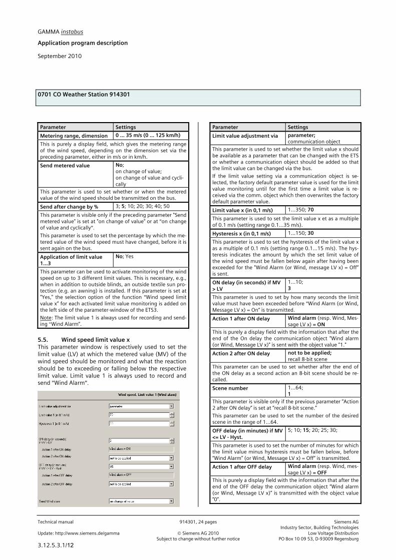
5.5. Wind speed limit value x This parameter window is respectively used to set the limit value (LV) at which the metered value (MV) of the wind speed should be monitored and what the reaction should be to exceeding or falling below the respective limit value. Limit value 1 is always used to record and send "Wind Alarm".
Parameter Settings
Limit value adjustment via parameter; communication object
This parameter is used to set whether the limit value x should be available as a parameter that can be changed with the ETS or whether a communication object should be added so that the limit value can be changed via the bus.
If the limit value setting via a communication object is se-lected, the factory default parameter value is used for the limit value monitoring until for the first time a limit value is re-ceived via the comm. object which then overwrites the factory default parameter value.
Limit value x (in 0,1 m/s) 1...350; 70
This parameter is used to set the limit value x et as a multiple of 0.1 m/s (setting range 0.1...35 m/s).
Hysteresis x (in 0,1 m/s) 1...150; 30
This parameter is used to set the hysteresis of the limit value x as a multiple of 0.1 m/s (setting range 0.1...15 m/s). The hys-teresis indicates the amount by which the set limit value of the wind speed must be fallen below again after having been exceeded for the "Wind Alarm (or Wind, message LV x) = Off“ is sent.
ON delay (in seconds) if MV > LV
1...10; 3
This parameter is used to set by how many seconds the limit value must have been exceeded before "Wind Alarm (or Wind, Message LV x) = On“ is transmitted.
Action 1 after ON delay Wind alarm (resp. Wind, Mes-sage LV x) = ON
This is purely a display field with the information that after the end of the On delay the communication object "Wind alarm (or Wind, Message LV x)" is sent with the object value "1."
Action 2 after ON delay not to be applied; recall 8-bit scene
This parameter can be used to set whether after the end of the ON delay as a second action an 8-bit scene should be re-called.
Scene number 1...64; 1
This parameter is visible only if the previous parameter “Action 2 after ON delay” is set at “recall 8-bit scene.”
This parameter can be used to set the number of the desired scene in the range of 1...64.
OFF delay (in minutes) if MV <= LV - Hyst.
5; 10; 15; 20; 25; 30;
This parameter is used to set the number of minutes for which the limit value minus hysteresis must be fallen below, before “Wind Alarm” (or Wind, Message LV x) = Off“ is transmitted.
Action 1 after OFF delay Wind alarm (resp. Wind, mes-sage LV x) = OFF
This is purely a display field with the information that after the end of the OFF delay the communication object “Wind alarm (or Wind, Message LV x)” is transmitted with the object value “0”.

GAMMA instabus
Application program description
September 2010
0701 CO Weather Station 914301
Siemens AG 914301, 24 pages Technical manual Industry Sector, Building Technologies Low Voltage Distribution © Siemens AG 2010 Update: http://www.siemens.de/gamma PO Box 10 09 53, D-93009 Regensburg Subject to change without further notice
3.12.5.3.1/13
Parameter Settings
Action 2 after OFF delay not to be applied; recall 8-bit scene
Using this parameter it can be set whether at the end of the Off delay as a second action an 8-bit scene should be recalled.
Scene number 1...64; 1
This parameter is visible only when the previous parameter "Action 2 after Off delay" is set to ”Recall 8-bit scene". This parameter can be used to set the number of the desired scene in the range of 1...64.
Send wind alarm (resp.: Wind, Message LV x)
on change of value; on change of value and cycli-cally
This parameter is used to set whether or when the object "Wind Alarm (or Wind, Message LV x)" should be sent on the bus.
Cycle time Wind alarm (resp. Wind, Message LV x) (in minutes)
3...15; 7
This parameter is visible only if the previous parameter “Send wind alarm (or Wind, message LV x)” is set at “on change of value and cyclically.”
Using this parameter the cycle time can be set in the range of 3...15 minutes.
5.6. Brightness This parameter window is used to adjust the desired properties of the brightness measurement and monitor-ing. Moreover, monitoring the brightness on up to 3 ad-justable limit values can be activated.
Parameter Settings
Metering range, dimension 0 ... 150 kLux
This is purely a display field, indicating the metering range of the brightness.
Parameter Settings
Send metered value No; on change of value; on change of value and cycli-cally
This parameter is used to set whether or when the brightness metered value should be sent on the bus.
Send after change by % 3; 5; 10; 15; 20; 25; 30; 40; 50
This parameter is visible only if the previous parameter “Send metered value” is set at “on change of value” or at "on change of value and cyclically."
This parameter is used to set the percentage by which the brightness metered value must have changed before it is sent on the bus again.
Application of limit value 1...3
No; Yes
This parameter can be used to activate the monitoring of the brightness metered value on up to 3 different limit values. This is necessary, e.g., when the measured brightness value is to be used not only for shade control, but also for lighting control.
If this parameter is set at "Yes," the selection option of the function "Brightness limit value x" for each activated limit value monitoring is added on the left side of the parameter window of the ETS3.
Note: The limit value 1 is always used for recording and transmitting "Sunshine".
5.7. Brightness limit value x This parameter window is used to respectively set the limit value to which the brightness metered value should be monitored and what the reaction should be to exceeding the limit value or at the end of exceeding. The limit value 1 is always used for recording and send-ing "Sunshine."

GAMMA instabus
Application program description
September 2010
0701 CO Weather Station 914301
Technical manual 914301, 24 pages Siemens AG Industry Sector, Building Technologies Update: http://www.siemens.de/gamma © Siemens AG 2010 Low Voltage Distribution Subject to change without further notice PO Box 10 09 53, D-93009 Regensburg
3.12.5.3.1/14
Parameter Settings
Limit value adjustment via parameter; communication object
This parameter is used to set whether the limit value x should be available as a parameter that can be changed only with the ETS or whether a communication object should be added so that the limit value can be changed via the bus.
If the limit value setting via a communication object is se-lected, the factory default parameter value is used for limit value monitoring until for the first time a limit value is re-ceived via the comm. object, which then overwrites the fac-tory default parameter value.
Limit value x (in kLux) 1...99; 70
This parameter is used to set the limit value x in kLux (setting range 1...99 kLux).
Note: The limit value 1 always serves for recording and trans-mitting “Sunshine”.
Hysteresis x (in kLux) 1...20; 10
This parameter is used to set the hysteresis of the limit value x in kLux (setting range 1...20 kLux). The hysteresis indicates the amount by which the set brightness limit value must be fallen below again after having been exceeded so that "Sun-shine (or Brightness, Message LV x) = Off" is transmitted.
ON delay if MV > LV 5s; 10s; 15s; 30s; 1 Min.; 2 Min.; 3 Min.; 5 Min.
This parameter is used to set how long the limit value must be exceeded before "Sunshine (or Brightness, Message LV x) = On" is sent.
Action 1 after ON delay Sunshine (resp. Brightness, Message LV x) = ON
This is purely a display field with the information that after the end of the ON delay the communication object "Sunshine (or Brightness, Message LV x)" is sent with the object value "1".
Action 2 after ON delay not to be applied; recall 8-bit scene
This parameter can be used to set whether at the end of the ON delay as the second action an 8-bit scene should be re-called.
Scene number 1...64; 1
This parameter is visible only when the previous parameter "Action 2 after ON delay" is set at "recall 8-bit scene."
Using this parameter the number of the desired scene can be set in the range of 1...64.
OFF delay 1 (in minutes) if MV <= LV - Hyst.
1...15; 5
This parameter is used to set for how many minutes the limit value minus hysteresis must be fallen below before “Sunshine (or Brightness, Message LV x) = Off“ is transmitted.
Action 1 after OFF delay 1 Sunshine (resp. Brightness, message LV x) = OFF
This is purely a display field with the information that after the end of the OFF delay 1 the communication object "Sunshine
Parameter Settings
(or Brightness, Message LV x)" is sent with the object value "0". After this a latency of ca. 2.5 s will always be kept before sending the next telegram.
Action 2 after OFF delay 1 not to be applied; recall 8-bit scene
This parameter can be used to set whether at the end of the OFF delay 1 as the second action an 8-bit Scene should be re-called.
Scene number 1...64; 1
This parameter is visible only if the previous parameter “Action 2 after OFF delay 1” is set at “recall 8-bit scene. ”
This parameter can be used to set the number of the desired scene in the range from 1...64.
Send Sunshine (resp. Bright-ness, Message LV x)
on change of value; on change of value and cycli-cally
This parameter is used to set whether or when the object "Sunshine (or Brightness, Message LV x)" should be sent on the bus.
Cycle time Sunshine (resp. Brightness, Message LV x) (in minutes)
3...15; 7
This parameter is visible only if the previous parameter "Send sunshine (or Brightness, Message LV x)" is set at "on change of value and cyclically".
This parameter can be used to set the cycle time in the range from 3...15 minutes.
5.8. Twilight This parameter window can be used to activate the monitoring of the brightness metered value on up to 3 adjustable twilight limit values. Limit value 1 is always used for recording and sending "Darkness."
Parameter Settings
Application of limit value 1 … 3
No; Yes
This parameter can be used to activate the monitoring of the brightness metered value on up to 3 different twilight limit values. This is necessary, e.g., when the measured brightness value is to be used not only for sun protection control (lower blinds / shutters in the evening as privacy protection and raise them in the morning) but also as lighting control (switch on exterior lighting in the evening and switch it off in the morn-

GAMMA instabus
Application program description
September 2010
0701 CO Weather Station 914301
Siemens AG 914301, 24 pages Technical manual Industry Sector, Building Technologies Low Voltage Distribution © Siemens AG 2010 Update: http://www.siemens.de/gamma PO Box 10 09 53, D-93009 Regensburg Subject to change without further notice
3.12.5.3.1/15
ing).
If this parameter is set at “Yes,” the selection option of the function "Twilight limit value x“ for each activated limit value monitoring is added on the left side of the parameter window of the ETS3.
Note: The limit value 1 is always used for recording and send-ing “Darkness.”
5.9. Twilight limit value x This parameter window is used respectively to set to which twilight limit value the brightness metered value should be monitored and what the reaction should be to falling below the limit value or at the end of falling be-low it. The limit value 1 is always used for recording and sending "Darkness."
Parameter Settings
Limit value adjustment via parameter; communication object
This parameter is used to set whether the limit value x should be available as a parameter that can be changed only with the ETS or whether a communication object should be added so that the limit value can be changed via the bus.
If the limit value setting is selected via a communication ob-ject, the factory default parameter value is used for limit value monitoring until for the first time a limit value is received by the comm. object that exceeds the factory default parameter value.
Limit value x (in Lux) 1...1000; 200
This parameter is used to set the limit value x in Lux (setting range 1...1000 Lux).
Hysteresis x (in Lux) 1...200; 10
This parameter is used to set the hysteresis of the limit value in Lux (setting range 1...200 Lux). The hysteresis indicates the
Parameter Settings
amount by which the set twilight limit value after having been fallen below must then be exceeded again for "Darkness" (or twilight, Message LV x) =OFF“ to be sent.
ON delay if MV < LV 5s; 10s; 15s; 30s; 1 Min.; 2 Min.; 3 Min.; 5 Min.
This parameter is used to set how long the twilight limit value must be fallen below before "Darkness (or Twilight, Message LV x) = ON“ is sent.
Action 1 after ON delay Darkness (resp. Twilight, message LV x) = ON
This is purely a display field with the information that after the ON delay the communication object "Darkness (or Twilight, Message LV x)” is sent with the object value "1."
Action 2 after ON delay not to be applied; recall 8-bit scene
This parameter can be adjusted whether at the end of the ON delay as the second action an 8-bit scene should be recalled.
Scene number 1...64; 1
This parameter is visible only when the previous parameter "Action 2 after ON delay“ is set at "recall 8-bit scene."
Using this parameter the number of the desired scene can be set in the range of 1...64.
OFF delay (in minutes) if MV >= LV + Hyst.
1...15; 15
This parameter is used to set how many minutes the limit value plus hysteresis must be exceeded before "Darkness (or Twilight, Message LV x) = Off" is sent.
Action 1 after OFF delay Darkness (or twilight, mes-sage LV x) = OFF
This is purely a display field with the information that after the end of the OFF delay the communication object "Darkness (or Twilight, Message LV x)" is sent with the object value "0."
Action 2 after OFF delay not to be applied; recall 8-bit scene
This parameter can be used to set whether at the end of the OFF delay as second action an 8-bit scene should be recalled.
Scene number 1...64; 1
This parameter is visible only if the previous parameter “Action 2 after OFF delay” is set at “recall 8-bit scene.”
Using this parameter the number of the desired scene can be set in the range from 1...64.
Send Darkness (resp. Twi-light, Message LV x)
on change of value; on change of value and cycli-cally
This parameter is used to set whether or when the object "Darkness (or Twilight, Message LV x)" should be sent on the bus.
Cycle time Darkness (resp. Twilight, Message LV x) (in minutes)
3...15; 7
This parameter is visible only when the previous parameter

GAMMA instabus
Application program description
September 2010
0701 CO Weather Station 914301
Technical manual 914301, 24 pages Siemens AG Industry Sector, Building Technologies Update: http://www.siemens.de/gamma © Siemens AG 2010 Low Voltage Distribution Subject to change without further notice PO Box 10 09 53, D-93009 Regensburg
3.12.5.3.1/16
Parameter Settings
"Send darkness (or Twilight, Message LV x)" is set at "on change of value and cyclically."
This parameter can be used to set the cycle time in the range from 3...15 minutes.
5.10. Precipitation This parameter window is used to set when the object "Precipitation alarm" should be sent and whether an additional action should be carried out with "Precipita-tion alarm = ON" or with "Precipitation alarm = Off." Note: The delay times with the recognition of precipita-tion are fixed and cannot be changed by the user.
Parameter Settings
Send Precipitation alarm ON / OFF
on change of value; on change of value and cycli-cally
This parameter is used to set whether or when the object "Precipitation alarm" should be sent on the bus.
Cycle time Precipitation alarm (in minutes)
3...15; 7
This parameter is visible only when the previous parameter "Send Precipitation alarm ON / OFF“ is set at "on change of value and cyclically“.
This parameter can be used to set the cycle time in the range of 3...15 Minutes.
Action if Precipitation alarm = ON
not to be applied; recall 8-bit scene
This parameter can be used to set whether with "Precipitation alarm = ON“ as an additional action an 8-bit scene should be recalled.
Scene number 1...64; 1
This parameter is visible only when the previous parameter "Action if "Precipitation Alarm = ON“ is set at "recall 8-bit scene".
This parameter can be used to set the number of the desired scene in the range of 1...64.
Action if Precipitation alarm = OFF
not to be applied; recall 8-bit scene
This parameter can be used to set whether with "Precipitation
Parameter Settings
alarm = OFF" as additional action an 8-bit scene should be re-called.
Scene number 1...64; 1
This parameter is visible only when the previous parameter "Action if Precipitation alarm = OFF" is set at "recall 8-bit scene".
This parameter can be used to set the number of the desired scene in the range of 1...64.
5.11. Outside temperature This parameter window is used to set the desired prop-erties of the temperature measurement and transmis-sion. Furthermore, the monitoring of the temperature on up to 3 adjustable limit values can be activated. Limit value 1 is always used for recording and sending "Frost-Alarm."
Parameter Settings
Send metered value with dimension
°C; °F
This parameter can be used to set whether the measured out-side temperature should be sent on the bus as a 16-bit float-ing point number with the dimension "°C" or converted with the dimension "°F."
Metering range, dimension -30 ... +50 °C
This is purely a display field that indicates the metering range of the outside temperature.
Temperature offset (in 0,1 K) -50 ... +50; 0
This parameter can be used to change the metered value by an adjustable offset value, in order to thus align it e.g., with a calibrated thermometer.
GAMMA instabus
Application program description
September 2010
0701 CO Weather Station 914301
Siemens AG 914301, 24 pages Technical manual Industry Sector, Building Technologies Low Voltage Distribution © Siemens AG 2010 Update: http://www.siemens.de/gamma PO Box 10 09 53, D-93009 Regensburg Subject to change without further notice
3.12.5.3.1/17
Parameter Settings
Send metered value No; on change of value; on change of value and cycli-cally
This parameter is used to set whether or when the tempera-ture metered value should be sent on the bus.
Send after change by 0,5 K; 1,0 K; 2,0 K
This parameter is visible only when the previous parameter "Send metered value" is set at "on change of value" or at "on change of value and cyclically."
This parameter is used to set by how many degrees Kelvin the temperature metered value must have changed before it is sent again on the bus.
Application of limit value 1 … 3
No; Yes
This parameter can be used to activate the monitoring of the outside temperature on up to 3 different limit values. This is necessary, e.g., when the outside temperature is to be moni-tored not only via the limit value 1 for a frost limit.
If this parameter is set at "Yes," the selection option of the function "Outside temperature limit value x" for each activated limit value monitoring is added on the left side of the parame-ter window of the ETS3.
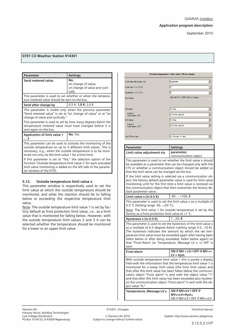
5.12. Outside temperature limit value x This parameter window is respectively used to set the limit value at which the outside temperature should be monitored, and what the reaction should be to falling below or exceeding the respective temperature limit value. Note: The outside temperature limit value 1 is set by fac-tory default as frost protection limit value, i.e., as a limit value that is monitored for falling below. However, with the outside temperature limit values 2 and 3 it can be selected whether the temperature should be monitored for a lower or an upper limit value.
Parameter Settings
Limit value adjustment via parameter; communication object
This parameter is used to set whether the limit value x should be available as a parameter that can be changed only with the ETS or whether a communication object should be added so that the limit value can be changed via the bus.
If the limit value setting is selected via a communication ob-ject, the factory default parameter value is used for limit value monitoring until for the first time a limit value is received via the communication object that then overwrites the factory de-fault parameter value.
Limit value x (in 0.5 K) -60 ... +100; 2
This parameter is used to set the limit value x as a multiple of 0.5 °C (Setting range -30...+50 °C).
Note: The limit value 1 for outside temperature is set by the factory as a frost protection limit value at +1 °C.
Hysteresis x (in 0.5 K) 1...20; 6
This parameter is used to set the hysteresis of the limit value x as a multiple of 0.5 degrees Kelvin (setting range 0.5...10 K). The hysteresis indicates the amount by which the set tem-perature limit value must be exceeded again after having been fallen below or after being exceeded, fallen below again) so that "Frost-Alarm (or Temperature, Message LV x =) Off" is sent.
Frost alarm ON if MV < LV / OFF if MV >= LV + Hyst.
With outside temperature limit value 1 this is purely a display field with the information that the temperature limit value 1 is monitored for a lower limit value (the frost limit value) and that after this limit value has been fallen below the communi-cation object "Frost alarm“ is sent with the object value "1" and that after this limit value has been exceeded plus hystere-sis the communication object "Frost alarm“ is sent with the ob-ject value "0."
Temperature, Message LV x ON if MV<LV / OFF if MV>=LV+Hyst.; ON if MV>LV / OFF if MV<=LV-

GAMMA instabus
Application program description
September 2010
0701 CO Weather Station 914301
Technical manual 914301, 24 pages Siemens AG Industry Sector, Building Technologies Update: http://www.siemens.de/gamma © Siemens AG 2010 Low Voltage Distribution Subject to change without further notice PO Box 10 09 53, D-93009 Regensburg
3.12.5.3.1/18
Parameter Settings
Hyst.
With outside temperature limit values 2 and 3 it is adjustable whether they are to be monitored for a lower limit value (ON when MV<LV / Off when MV>=LV+Hyst.) or for an upper limit value (ON when MV>LV / OFF when MV<=LV-Hyst.).
ON-delay 1s; 3s; 5s; 10s; 15s; 30s; 1 Min.; 2 Min.; 3 Min.; 5 Min.; 10 Min.; 15 Min.; 30 Min.; 1 h
This parameter is used to set how long the temperature limit value, has to be fallen below (or exceeded) before "Tempera-ture, Message LV x = ON" is sent.
Action if Frost alarm (resp. Temperature, Message LV x) = ON
not to be applied; recall 8-bit scene
It can be adjusted via this parameter whether at the end of the ON delay as an additional action an 8-bit scene should be re-called.
Scene number 1...64; 1
This parameter is visible only when the previous parameter "Action if Frost alarm (or Temperature, Message LV x) = ON" is set at "recall 8-bit scene".
This parameter can be used to set the number of the desired scene in the range from 1...64.
OFF-delay 1s; 3s; 5s; 10s; 15s; 30s; 1 Min.; 2 Min.; 3 Min.; 5 Min.; 10 Min.; 15 Min.; 30 Min.; 1 h
This parameter is used to set how long falling below (or ex-ceeding) the limit value must have been completed taking into account the hysteresis so that "Frost alarm (or Tempera-ture, Message LV x) = OFF” is sent.
Action if Frost alarm (or Temperature, Message LV x) = OFF
not to be applied; recall 8-bit scene
This parameter can be used to set whether at the end of the OFF delay as an additional action an 8-bit scene should be re-called.
Scene number 1...64; 1
This parameter is visible only when the previous parameter "Action if Frost alarm (or Temperature, Message LV x) = OFF" is set at "recall 8-bit scene".
This parameter can be used to set the number of the desired scene in the range of 1...64.
Send Frost alarm (resp. Tem-perature, Message LV x)
on change of value; on change of value and cycli-cally
This parameter is used to set whether or when the object "Frost alarm (or Temperature, message LV x)" should be sent on the bus.
Cycle time Frost alarm (resp. Temperature, Message LV x) (in minutes)
3...15; 7
This parameter is visible only when the previous parameter "Send Frost alarm (or Temperature, message LV x)“ is set at
Parameter Settings
"on change of value and cyclical."
Using this parameter the cycle time can be set in the range from 3...15 minutes.
5.13. Safety Using this parameter window up to 8 alarm objects can be logically combined via an OR function to the object "Safety." Note: Usually with the object "Safety" at the addressed sun protection actuators a movement into the safety position is triggered (e.g. the upper end position) and leaving this end position is blocked as long as the object "Safety" has the logical value "1."
Parameter Settings
Add object External alarm 1; 2; 3
This parameter determines the number of available communi-cation objects for “External alarm” (1…7), which allow recep-tion of e.g. a wind alarm from a wind alarm sensor per façade.
Note: External alarm inputs are not monitored i.e. failure of an alarm sensor is not detected.
If: not to be applied Wind alarm = ON;
This parameter is used to set whether the object "Wind alarm" with the logical value "1" should be combined via this OR function to the safety object.
OR not to be applied Wind, Message LV 2 = ON;
This parameter is used to set whether the object "Wind, Mes-sage LV 2" with the logical value "1" should be combined via this OR function to the safety object.
OR not to be applied Wind, Message LV 3 = ON;
This parameter is used to set whether the object "Wind, Mes-
GAMMA instabus
Application program description
September 2010
0701 CO Weather Station 914301
Siemens AG 914301, 24 pages Technical manual Industry Sector, Building Technologies Low Voltage Distribution © Siemens AG 2010 Update: http://www.siemens.de/gamma PO Box 10 09 53, D-93009 Regensburg Subject to change without further notice
3.12.5.3.1/19
Parameter Settings
sage LV3" with the logical value "1" should be combined via this OR function to the safety object.
OR not to be applied Precipitation alarm = ON;
This parameter is used to set whether the object “Precipitation alarm“ with the logical value "1" should be combined via this OR function to the safety object.
OR not to be applied Frost alarm = ON;
This parameter is used to set whether the object "Frost alarm" with the logical value "1" should be combined via this OR func-tion to the safety object.
OR not to be applied External alarm 1 = ON; External alarm 2 = ON; External alarm 3 = ON;
This parameter is used to set whether respectively which of the objects "External alarm" with the logical value "1" should be combined via this OR function to the safety object.
OR not to be applied Wind sensor, Failure = ON;
This parameter is used to set whether the object “Wind sen-sor, Failure" with the logical value "1" should be combined via this OR function to the safety object.
OR not to be applied Output OR logic operation 1 = ON; Output OR logic operation 2 = ON; Output OR logic operation 3 = ON; Output OR logic operation 4 = ON; Output AND logic oper. 1 = ON; Output AND logic oper. 2 = ON; Output AND logic oper. 3 = ON; Output AND logic oper. 4 = ON
This parameter is used to set whether one of the output ob-jects of the 4 OR functions or the 4 AND functions with the logical value "1" should be combined via this OR function to the safety object.
then: Safety = ON
This is purely a display field. It shows that the object "Safety" is sent with the logical value "1" when the set conditions of the logical OR function have been met.
Send Safety on change of value; on change of value and cycli-cally
This parameter is used to set when the object "Safety" should be sent on the bus.
Cycle time Safety (in minutes)
3...15; 7
This parameter is visible only when the previous parameter "Send Safety“ is set at "on change of value and cyclically."
This parameter can be used to set the cycle time in the range of from 3...15 minutes.
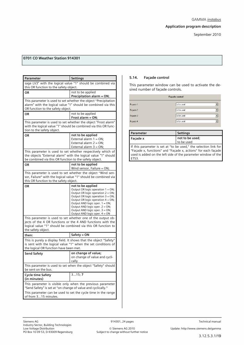
5.14. Façade control
This parameter window can be used to activate the de-sired number of façade controls.
Parameter Settings
Façade x not to be used; to be used
If this parameter is set at "to be used," the selection link for "Façade x, functions" and "Façade x, actions" for each façade used is added on the left side of the parameter window of the ETS3.

GAMMA instabus
Application program description
September 2010
0701 CO Weather Station 914301
Technical manual 914301, 24 pages Siemens AG Industry Sector, Building Technologies Update: http://www.siemens.de/gamma © Siemens AG 2010 Low Voltage Distribution Subject to change without further notice PO Box 10 09 53, D-93009 Regensburg
3.12.5.3.1/20
5.15. Façade x, functions Using this parameter window for each façade the char-acteristic values (alignment, inclination, blind angle) are entered and determined which communication object (or which command) is to be transmitted to lower the sun protection as soon as the sun begins to shine on the façade and to raise the sun protection as soon as the sun can no longer shine on the façade.
Parameter Settings
Orientation (North=0°, E=90°, S=180°, W=270°)
0...359; 0
Using this parameter analogously to the wind rose, the direc-tion is entered in which the vertical shows on the façade sur-face or, with a sloping roof, the direction in which the vertical would show on the sloping roof set vertically. North is hereby 0°, east 90°, etc.
Inclination (against base point of vertical)
-89...+60; 0
This parameter is used to enter by how many degrees the fa-çade surface is tilted with respect to the base point of vertical. A forward inclination of the façade is counted as positive here, a backward inclination as negative. Roofs therefore have a negative inclination (-90° corresponds to a flat roof).
Blind angle horizontal 2...25; 2
This parameter is used to set whether the solar protection should be activated immediately when the sun begins to shine on the façade from the side (horizontal blind angle > 0°) or whether it should be activated later when the rays of the sun fall on the façade at an angle that is greater than the set hori-zontal blind angle. A blind angle occurs, e.g., through a lateral projection (wall projection).
Note: The horizontal blind angle set is presumed to be the same size on both sides (i.e. the same size both on the right and on the left side of the façade).
Blind angle vertical 2...45; 2
This parameter is used to set whether the solar protection should be activated immediately when the sun begins to shine
Parameter Settings
on the façade vertically from above (vertical blind angle > 0°) or whether it should be activated somewhat later because, e.g., the roof projects somewhat and the rays of the sun do not fall onto the façade until the vertical blind angle is ex-ceeded.
Shading control via Brightness Limit value 1 (Sunshine); Brightness, Limit value 2; Brightness, Limit value 3
This parameter is used to establish which of the 3 brightness limit values (or which object "brightness, Message LV x = ON/OFF") should be applied in calculating whether the sun is shining on the current façade.
OFF delay 2 in minutes if Brightness, Message LV = OFF
1...15; 10
So that the solar protection of the façade is not immediately raised when sunshine is interrupted by a cloud, with the Off delay 2 a further delay time can be taken into consideration at the start of which e.g. the slats are placed horizontally for max. admission of light. When it is over, first the end of the sunshine is reported for the current façade and then the solar protection is raised.
Façade x, send Sunshine on change of value; on change of value and cyclically
This parameter is used to set when the object "Façade x, Sun-shine" should be sent on the bus.
Cycle time façade 1 in minutes 5...60; 15
This parameter is visible only when the previous parameter "Façade x, send Sunshine" is set at "on change of value and cyclically."
This parameter can be used to set the cycle time in the range from 5...60 minutes
5.16. Façade x, actions This parameter window is used for each façade to set which commands are to be sent as soon as the sun shines on the façade, while the sun is shining on the fa-çade and when the sun is no longer shining or can no longer shine on the façade. Moreover, it is set whether these commands in each case are to be sent only after a change or cyclically. Note: The object "Façade x, Sunshine = OFF" is sent without delay as soon as the sun can no longer shine on the façade x.

GAMMA instabus
Application program description
September 2010
0701 CO Weather Station 914301
Siemens AG 914301, 24 pages Technical manual Industry Sector, Building Technologies Low Voltage Distribution © Siemens AG 2010 Update: http://www.siemens.de/gamma PO Box 10 09 53, D-93009 Regensburg Subject to change without further notice
3.12.5.3.1/21
Parameter Settings
If Brightness, Message LV = ON, Action 1
Facade x, Sunshine = ON
This is purely a display field. It contains the message that if the brightness limit value selected for this façade is exceeded (i.e., the sun is indeed shining) and moreover the sun has reached a position from which it can shine on this façade, the object "Façade x, Sunshine“ is sent with the object value "1." This telegram can be used to lower (activate) the entire sun pro-tection for this façade.
If action 1 is followed by an action 2, the sending of the first telegram of action 2 will take place after a latency of ca. 2.5 s.
Action 2 not to be applied; Central command DOWN; Central command DOWN1; Blind position in %; Blind + slats position in %; recall 8-bit scene
This parameter field is purely a display field when one of the parameters "Shadow edge tracking" and "Sun tracking control of slats" is set at "Yes" or when both parameters are set at “Yes”.
If the parameter “Shadow edge tracking“ is set at “Yes,“ it con-tains the information that the object "Blind position in %“ is sent.
If the parameter "Sun tracking control of slats" is set at "Yes," it contains the message that the object "Slats position in %" is sent.
If both parameters "Shadow edge tracking" and "Sun tracking control of slats" are set at "Yes," it contains the message that both the object "Blind position in %" as well as the object "Slats position in %" are sent.
If the parameters "Shadow edge tracking" and "Sun tracking control of slats" are set at "No" it can be set here whether a command object is to be sent and, if so, which one as soon as the sun shines on the façade:
- Central command DOWN: the object "Façade x, blind cen-trally UP/DOWN" with the object value "1" is sent once. With Siemens actuators this is to be linked with the object "Chan-
Parameter Settings
nels A-X, Automatic operation = On + centrally Up/ Down." Through this firstly all the actuator channels are switched to automatic operation and then the addressed sun protection is moved into the lower end position. It is thus ensured that with the start of sunshine all the sun protection devices of the fa-çade concerned will be lowered and all the channels will be in automatic operation, as long as the occupant of the room does not disable the automatic operation for the sun protec-tion devices that he can control.
- Central command DOWN1: The object "Façade x, Blind cen-trally DOWN1" with the object value "1" is sent once, via which all the actuator channels are switched to automatic operation and the addressed sun protection drives with 3 limit switches are moved into the DOWN1 end position with opened slats. (Warning: This command can be used only with blind actua-tors that can control drives with 3 limit switches!)
- Blind position in %: The object "Façade x, Blind position in %" is sent once with an object value that is determined via the parameter subsequently shown with this setting.
- Blind + slats position in %: The objects "Façade x, Blind posi-tion in %" and "Façade x, Slats position in %" are sent once with an object value that is determined via the parameter sub-sequently shown in each case.
- Recall 8-bit scene: The object "8-bit scene" is sent once with a scene number that is established via the parameter subse-quently shown.
Blind position in % 50...100; 100
This parameter is visible only when the previous parameter “Action 2“ is set to “Blind position in %“ or to “Blind + slats po-sition in %”.
It is used to set in the range of 50...100% how far the sun pro-tection should be closed (100% = completely closed).
Slats position in % 50...100; 100
This parameter is visible only when the previous parameter "Action 2“ is set at "Blind + slats position in %."
It is used to set in the range of from 50...100% how far the slats are to be closed (100% = completely closed).
Scene number 1...64; 1
This parameter is visible only when the previous parameter "Action 2“ is set to "Recall 8-bit scene.”
This parameter can be used to set the number of the desired scene in the range from 1...64.
Send blind position in % on change of value; on change of value and cycli-cally
This parameter is visible only when in the "Façade x, func-tions" parameter window the parameter "Shadow edge track-ing" is set at “Yes”.
This parameter is used to set when the object "Façade x, Blind position in %" should be sent on the bus.
Send slats position in % on change of value; on change of value and cycli-cally
This parameter is visible only when in the "Façade x, func-

GAMMA instabus
Application program description
September 2010
0701 CO Weather Station 914301
Technical manual 914301, 24 pages Siemens AG Industry Sector, Building Technologies Update: http://www.siemens.de/gamma © Siemens AG 2010 Low Voltage Distribution Subject to change without further notice PO Box 10 09 53, D-93009 Regensburg
3.12.5.3.1/22
Parameter Settings
tions" parameter window the parameter "Sun tracking control of slats" is set at “Yes”.
This parameter is used to set when the object "Façade x, slats position in %" should be sent on the bus.
Send blind + slats position in %
on change of value; on change of value and cycli-cally
This parameter is visible only when in the parameter window "Façade x, functions" both parameters "Shadow edge tracking" and "Sun tracking control of slats" are set at “Yes”.
This parameter is used to set when the objects "Façade x, Blind position in %“ and "Façade x, Slats position in %" are to be sent on the bus.
Cycle time Blind / slats position façade 1 in minutes
5...60; 15
This parameter is visible only if one of the previous parameters "Send blind position in %" or "Send slats position in %" or "Send blind + slats position" is set to "on change of value and cyclical."
This parameter can be used to set the cycle time for setting sun protection and slats position in the range of 5...60 min-utes.
If Brightness, Message LV = OFF, Action
not to be applied; blind stepwise UP; slats position in %
If the sun is no longer shining and it has therefore fallen be-low the brightness limit value used for the control of the fa-çade minus hysteresis, at the end of the OFF delay 1 the ob-ject "Brightness, Message LV x" is sent with the object value "0."
With activated façade control this parameter can be used to set whether there should be a reaction to this event and what it should be.
- Not to be applied: There is no reaction, instead a wait in case the sunshine may return during the OFF delay 2.
- Blind stepwise UP: If shutters are used as sun protection, they can now be raised by an adjustable number of steps. The shutter slats and the shutters themselves are opened some-what so that a little more daylight reaches the rooms.
- Slats position in %: If Venetian blinds are used as sun protec-tion, their slats can be opened halfway to completely so that more daylight reaches the rooms.
Number of steps 1...7; 3
This parameter is visible only when the previous parameter "If brightness, Message LV = OFF, Action" is set at "Blind stepwise UP."
This parameter can be used to set by how many steps the sun protection should be raised after the end of OFF delay 1, when the sun is no longer shining.
Slats position in % 0...50; 0
This parameter is visible only if the previous parameter "If brightness, Message LV = OFF, Action" is set to “slats position in %."
Parameter Settings
This parameter is used to set in the range from 0...50% how far after the end of the Off delay 1, when the sun is no longer shining, the slats should be opened (0% = completely opened = horizontal position of the horizontal slats of Venetian blinds.
After OFF delay 2, Action 1 not to be applied; central command UP; blind position in %; blind + slats position in %; recall 8-bit scene
This parameter can be used to set (when the sun is still not shining after the end of the OFF delay 2) whether another command object should be transmitted and if so, which one.
- Central command UP: the object "Façade x, Blind centrally UP/DOWN" is sent once with the object value "0". If necessary, this object is to be linked with Siemens actuators with their object "Channels A-X, Automatic operation=On + central Up/Down". With the actuators thus firstly all the channels are switched to automatic operation and then the addressed sun protection is moved into the upper end position. It is thus en-sured that at the end of sunshine all of the sun protection de-vices of the façade concerned are raised and all channels are again in automatic operation.
- Blind position in %: the object "Façade x, Blind position in %" is sent once with an object value that is established via the pa-rameter subsequently shown with this setting.
- Blind + slats position in %: the objects "Façade x, Blind posi-tion in %" and "Façade x, Slats position in %" are sent once with an object value that is established in each case via the parameter subsequently shown.
- Recall 8-bit scene: this object is sent once with a scene num-ber that is stipulated via the parameter subsequently shown.
Blind position in % 0...100; 0
This parameter is visible only if the previous parameter "After OFF delay 2, Action 1" is set to "Blind position in %" or to "Blind + slats position in %."
It is used to set in a range from 0...100% how far the sun pro-tection is to be opened (0% = completely opened).
Slats position in % 0...100; 0
This parameter is visible only if the previous parameter "After OFF delay 2, Action 1" is set at "Blind + slats position in %."
It is used to set in a range from 0...100% how far the slats are to be opened (0% = completely opened).
Scene number 1...64; 1
This parameter is visible only if the previous parameter "After OFF delay 2, Action 1" is set at "recall 8-bit scene."
With this parameter the number of the desired scene can be set in the range of 1...64.
Action 2 Façade x, Sunshine = OFF
This is purely a display field. It contains the message that if the sun is still not shining after the end of the OFF delay 2, the ob-ject "Façade x, Sunshine" will be transmitted with the object value "0." This telegram can then be used to raise (deactivate) the entire sun protection for this façade.

GAMMA instabus
Application program description
September 2010
0701 CO Weather Station 914301
Siemens AG 914301, 24 pages Technical manual Industry Sector, Building Technologies Low Voltage Distribution © Siemens AG 2010 Update: http://www.siemens.de/gamma PO Box 10 09 53, D-93009 Regensburg Subject to change without further notice
3.12.5.3.1/23
5.17. Logic Using this parameter window up to 4 logical AND-functions and up to 4 logical OR-functions with up to 4 data inputs (objects) are activated. Since the result of the logic operation can be inverted, if required, an AND-function can be changed into a NAND-function and an OR-function into a NOR-function.
Parameter Settings
AND logic operation 1 (...4) inactive; active
Using this parameter the corresponding AND logic operation is activated.
OR-logic operation 1 (...4) inactive; active
Using this parameter the corresponding OR logic operation is activated.
5.18. AND logic operation x, OR logic operation x This parameter window is used to define for an AND / OR logic operation which object is assigned to an input, which actions should occur when the result of the logic operation is a logic 1 or a logic 0 and when or how the result should be transmitted on the bus.
Parameter Settings
1st input (... 4th input) not used; Object no. 6; ... Ob-ject no. 117 inverted
With this parameter an object of the weather station (from a list of approx. 40 objects) for logic combination with up to three further objects can be assigned to the corresponding in-put.
If logic operation = 1 Action 1: Object value =
0; 1
If the result of the logic operation is = 1, if required it can be inverted via this parameter, i.e., an AND function then be-comes a NAND function and an OR function a NOR function.
Action 2: not to be applied; recall 8-bit scene
If the result of the logic operation is = 1, as further action a se-lectable 8-bit scene can be recalled.
Scene number 1...64; 1
This parameter is visible only when the previous parameter "Action 2“ is set at "recall 8-bit scene“.
This parameter can be used to set the number of the desired scene in the range of 1...64.

GAMMA instabus
Application program description
September 2010
0701 CO Weather Station 914301
Technical manual 914301, 24 pages Siemens AG Industry Sector, Building Technologies Update: http://www.siemens.de/gamma © Siemens AG 2010 Low Voltage Distribution Subject to change without further notice PO Box 10 09 53, D-93009 Regensburg
3.12.5.3.1/24
Parameter Settings
If logic operation = 0, Action 1: Object value =
0; 1
If the result of the logic operation is = 0, if required it can be inverted via this parameter, i.e. an AND function then be-comes a NAND function and an OR function becomes a NOR function.
Note: If the parameter "If logic operation = 1, Action 1: Object value =" was set at "0", i.e., the result of the logic operation is inverted, it must be inverted here too and this parameter set at "1".
Action 2: not to be applied; recall 8-bit scene
If the result of the logic operation is = 0, as further action a se-lectable 8-bit scene can be recalled.
Scene number 1...64; 1
This parameter is visible only when the previous parameter "Action 2" is set at "recall 8-bit scene."
This parameter can be used to set the number of the desired scene in the range from 1...64.
Send logic object on change of value; on change of value and cycli-cally
This parameter is used to set when the result of the logic op-eration (i.e., the associated comm. object) should be sent on the bus.
Raum für Notizen