application of geometrical optics to the design and analysis … · the basic concepts of...
TRANSCRIPT
AcCRL-67-0501SEPTEMBER 1967PHYSICAL SCIENCES RESEARCH PAPERS, NO. 340
AIR FORCE CAMBRIDGE RESEARCH LABORATORIESL C% HANSCOM, FIELD, BEDFORD, MASSACHUSETTS
Application of Geometrical Opticsto the Design and Analysisof Microwave AntennasF. SHEPPARD HOLT
OFFICE OF AEROSPACE RESEARCH
United States Air Force
C L f A R N H 0 j S

IIBuf
Distribution of th~s document is unlimited. It may be re.leased to theCle~ringhouse. Department of Commerce, ?or sale to the general public.l
Quamlified requestors nmay obtern additional copies from the
Defense Documentation Center. All others ,3houid apply tc
the Clearinghouse for Federal Scientific and TechnicalInformation.
lone

N,,
AFCRL-67-0501SEPTEMBER 1967PHYSICAL SCIENCES RESEARCH PAPERS, NO. 340
MIrROWAVE PHYSICS LABORATORY PROJECT 5635
AiR FORCE CAMBRIDGE RESEARCH LABORATORIESL G. HANSCOM FIELD, BEDFORD, MASSACHUSETTS
Application of Geometrical Opticsto the Design and Analysisof Microwave AntennasF. SHEPPARD HOLT
Distribution of this document is unlimited. It may
be released to the Ctvaringhouse, Department ofCoaamerce, for sale to the general public.
OFFICE OF AEROSPACE RESEARCH
United States Air Force
tI
Abstract
The basic concepts of geometrical optics together with the additional aasump-
tions thal lead to the "geometrical optics approximation" are described here. The
eikonal equation is derived and the relationship of exact electromagnetic theory inthe limit as X - 0 to geometrical optics is made evident. The application of the"geometrical optics approximation" to phase analaysis and synthesis is described
and an example of synthesis is presented. The concept of power flow in ray tubesis used to obtain approximations to power distributions in the antenna aperture, in
the focal region, and in the far field. Ray analysis is used to determine those feedlocations in the focal region that will most nearly collimate the far-field rays thatlie in certain desirable planes. The Theorem of Malus is used to formulate the
equal path l2ngth law and applications are given. Focal surfaces (or caustics)relative to a rectilinear congruence are defined and then used to present a geometrical
optics description of the focal region. The equations of the focal surfaces of a para-boloid receiving a plane wave 200 off-axis are calculated and photographs of three-
dimensional models of the focal surfaces are shown.
-i-t--------i- ------ -- ---- - - - --
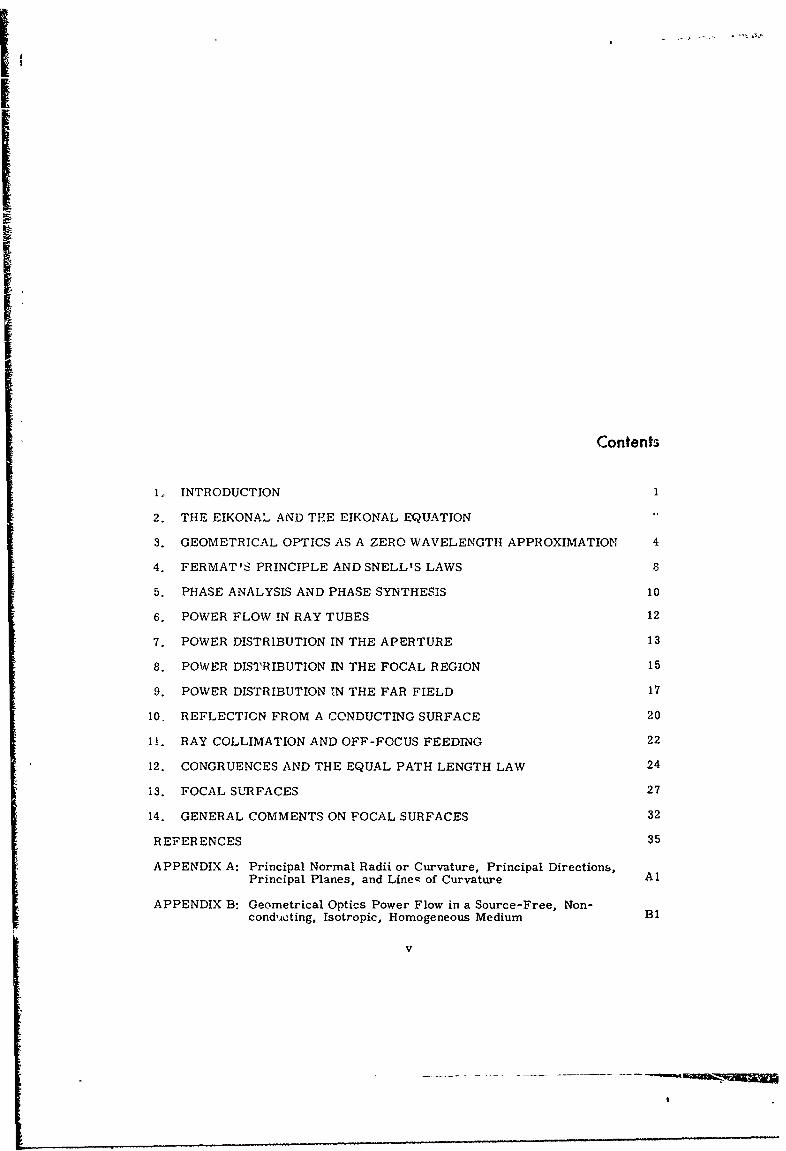
Contents
1, INTRODUCTION 1
2. THE EIKONAL AND THE EIKONAL EQUATION
3. GEOMETRICAL OPTICS AS A ZERO WAVELENGTH APPROXIMATION 4
4. FERMAT'S PRINCIPLE AND SNELL'S LAWS 8
5. PHASE ANALYSIS AND PHASE SYNTHESIS 10
6. POWER FLOW IN RAY TUBES 12
7. POWER DISTRIBUTION IN THE APERTURE 13
8. POWER DISTRIBUTION IN THE FOCAL REGION 15
9. POWER DISTRIBUTION TN THE FAR FIELD 17
10. REFLECTION FROM A CONDUCTING SURFACE 20
11. RAY COLLIMATION AND OFF-FOCUS FEEDING 22
12. CONGRUENCES AND THE EQUAL PATH LENGTH LAW 24
13. FOCAL SURFACES 27
14. GENERAL COMMENTS ON FOCAL SURFACES 32
REFERENCES 35
APPENDIX A: Principal Normal Radii or Curvature, Principal Directions,Principal Planes, and Lines of Curvature Al
APPENDIX B: Geometrical Optics Power Flow in a Source-Free, Non-cond'ucting, Isotropic, Homogeneous Medium B1
V
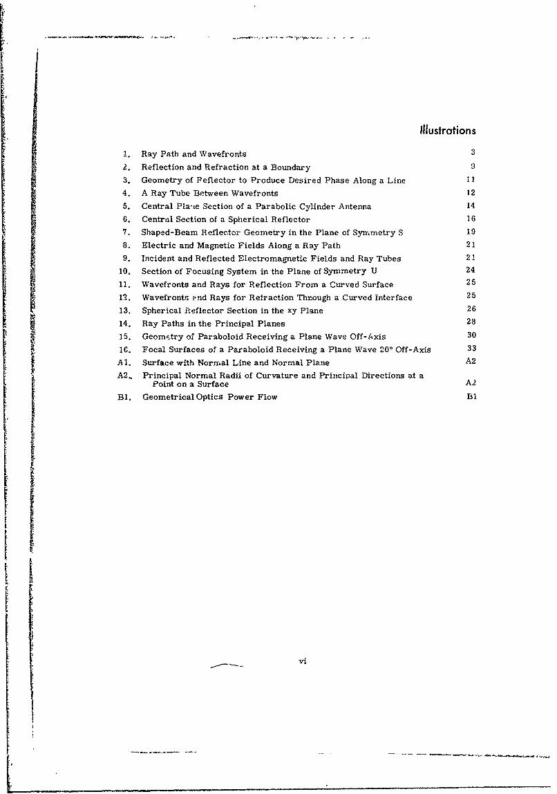
Illustrations
1. Ray Path and Wavefronts 3
2. Reflection and Refraction at a Boundary 9
3. Geometry of Peflector to Produce Desired Phase Along a Line i1
4. A Ray Tube Between Wavefronts 12
5. Central Pla',e Section of a Parabolic Cylinder Antenna 14
6. Central Section of a Spherical Reflector 16
7. Shaped-Beam Reflector Geometry in the Plane of Symmetry S 19
8, Electric and Magnetic Fields Along a Ray Path 21
9. Incident and Reflected Electromagnetic Fields and Ray Tubes 21
10. Section of Focusing System in the Plane of Symmetry U 2411. Wavefronts and Rays for Reflection From a Cuýrved Surface 25
12. Wavefronts .nd Rays for Refraction Through a Curved interface 25
13. Spherical Reflector Section in the xy Plane 26
14 Ray Paths in the Principal Planes 28
15 Geom,.try of Paraboloid Receiving a Plane Wave Off-Axis 30
1. Focal Surfaces of a Paraboloid Receiving a Plane Wave 200 Off-Axis 33A 1. Surface with Normal Line and Normal Plane A2
A2. Principal Normal Radii of Curvature and Prirnciral Directions at aPoint on a Surface A2
Bl. GeometricalOptics Power Flow B1
I
vi

Application of Geometrical Optics to the Design
and Analysis of Microwave Antennas
1. INTRODUCTION
This report is concerned with the laws, principles, and procedures of geomnet-rical optics that are applicable to the design and analysis of microwave antennas.
Geometrical optics, considered as a zero wavelength approximation to exact electro-magnetic wave theory, is very accurate in the design a'd analysis of optical focusingdevices because optical wavelengths are extremely small compared to the aperturedimensions of optical systems. At microwave frequencies, the wavelength is notalways relatively small compared to the aperature dimensions of microwave sys-tems. Geometrical optics, however, although certainly an approximation is stillsufficiently accurate to produce meaningful and useful results, even for antennaswith aperture dimensions as small as five wavelengths. The advantages of certainmicrowave components over existing optical components and the relaxation inmechanical tolerance requirements due to the finite wavelength allow the exploitationof geometrical optics analysis and design at microwave frequencies in certain casesconsiderably beyond that achievable in optics. For e.mmpie, low-loss isotropicartificial dielectrics in a wide range of index of refraction, phase and amplitudecontrol of sources and receivers, and aspheric as well as nonrotational symmetricreflecting and refracting surfaces are all available to the antenna designer.
(Received for publication 5 May 1967)
I
2
In general, geometrical optics is concerned with the analysis and synthesis
of optical systems to the approximation that diffraction and interference can be
neglected. In an isotropic medium, classical geometricaL optics assumes that the
power flows along paths called rays at a velocity characteristic of the medium and
that there exists a family of surfaces known as wavefronts that are everywhere
normal to the rays. Point-to-point correlatiop between wavefronts can be estab-
lished by the rays and no power is assumed to be present in regions where there
j are no rays. It is evident, that if all the wavefronts are given, all the rays are
determined and vice versa. Classical geometrical optics, therefore, neglects wave-
length, phase, and the vector nature of electromagnetic wave motion. For micro-
wave applications, it is most useful to extend the classical theory to include effects
of the above-neglected factors. The form of the extension is justified by the asymp-
totic solution as w - oo (X-.0) of the exact electromagnetic field equations to be
discussed in Section 3. The extension consists of introducing wavelength as a small
but finite quantity, identifying the wavefronts with equiphase surfaces, and at each
point on a ray in a homogeneous medium Introducing the electromagnetic field vec-
tor? E and H and relating them as in a plane wave propagating along the ray. We
shall refer to this extension as the geometrical optics approximation.
2. THE E;KONAL AND THE EIKONAL EQUATION
Using the geometrical optics approximation, gssume for a particular wave
motion in a scurce-iree isotropic mediumrn that the equiphase wavefronts are given
by the level surfaces of the function
j = L(x, y, z)
and that the phase b on a general wavefront W is given by
wt - 2L(x,y,z) (1)
)
where w is the angular frequency, c is the velocity in free space, and (V, y, z)
is any point on W. The function L(x, y, z) is known as the e.konal and, together
with the wavefront velocity in the medium, it completely describes the given wave
r motion from the standpoint of classical geometrical optics.
.. F
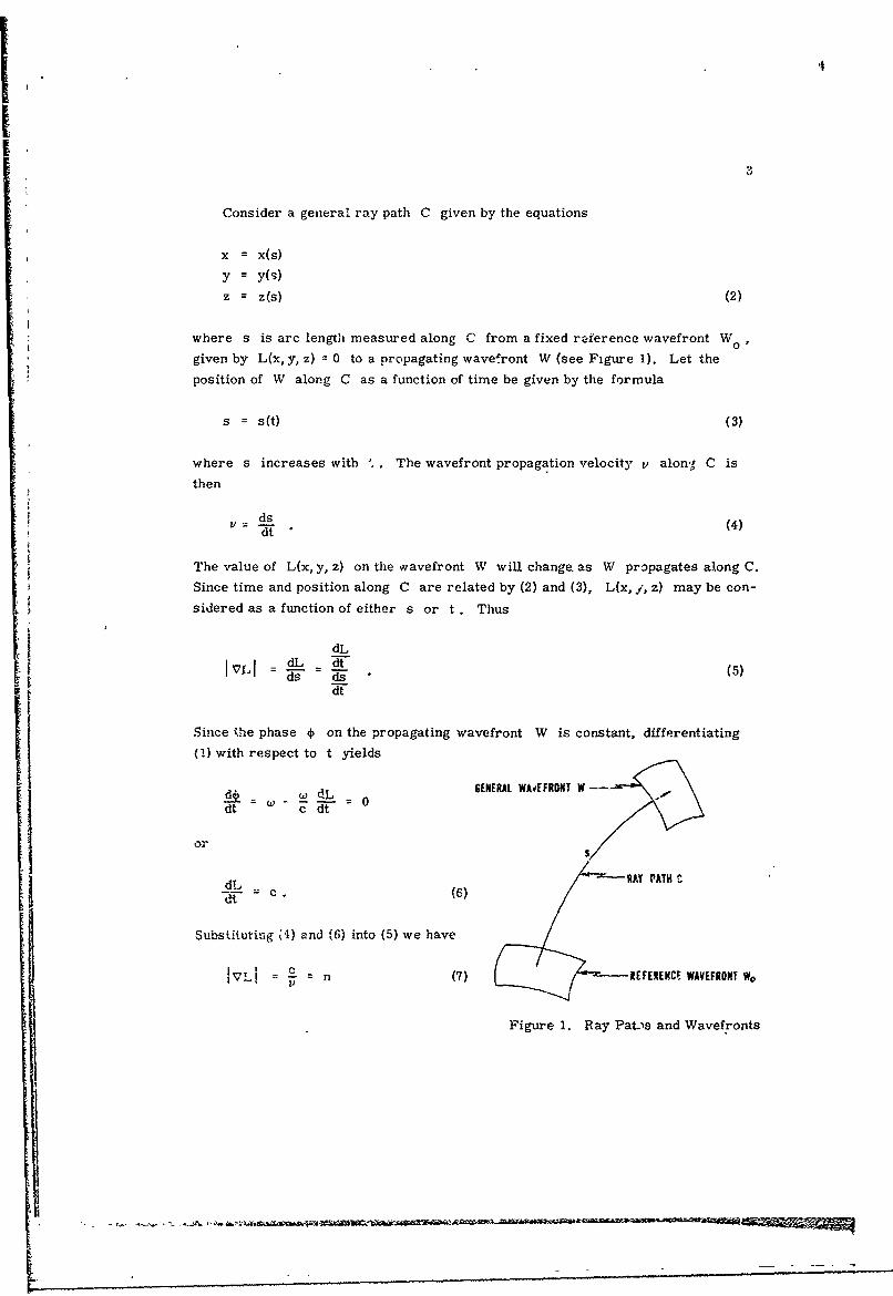
Consider a general ray path C given by the equations
x = x(s)
y = y(9)
z = z(s) (2)
where s is arc length measured along C from a fixed reference wavefront Wo
given by L(x, y, z) = 0 to a propagating wavefront W (see Figure 1). Let the
position of W along C as a function of time be given by the formula
s = s(t) (3)
where s increases with The wavefront propagation velocity v along, C is
then
v dsd (4)
The value of L(x, y, z) on the wavefront W will change. as W propagates along C.
Since time and position along C are related by (2) and (3), L(x, ., z) may be con-
sidered as a function of either s or t Thus
dL
Sds 1 (5)dt
Since ýhe phase * on the propagating wavefront W is constant, differentiating
(1) w i t h r e s p e c t t o t y i e l d s
= d 0 GENERAL WMvEFRONT W ---- .dd_ !! •_ .•. = 0,-dt c dt
S'
dL RAY PATH"t (6)
SubsUtutiug {') and (6) into (5) we haveI - n (7) REFERENCE WAVEFRONT W,
Figure 1. Ray Pat-is and Wavefronts
4I! where n is the index of refraction of the medium. The partial differential equa-
tion (7) satisfied by the eikonal 1,(x, y, z) is known as the eikonal equation. 4
The eikonal equation can be used to determine the curvature of ray paths in an
inhomogeneous medium. Assume a wave motion in an "nhomogeneous medium pre-
scribed by the eikonal L(x, y, z) and let C be a ray path with arc length s in the
direction of the wave motion. At each point on C let g be the unit tangent vect6r
in the direction of s , let flpbe the unit principal normal vector, and let p be the
radius if curvature. The vector VL evaluhted at any point P is normal to the
wavefront passing through the point P. Hence, at each point on C , the vector
j VL is along C and in view of ne eikonal equation (7),
VL _ (8)
The first Frenet formult (Hildebrand, 1949) of differential geometry can be written
" 9 = -V X (VX ) =p (9)ds . .. --
Substituting (8) into (9) we have
dq•S -9 X IV X VL X V1"O1n n) X•
and
1 d1.- • " = ft V (in n) =- f Vn. (10)ds -p n -p
Equation (10) shows that the ray-path curvature is related to the rate ofchange of the index of refraction n notmal to the ray path. In particular, for a
homogeneous medium (n constant) the curvature is zero and the ray paLhs are
straight lines.
j
3. GEOMETRICAL OPTICS AS A ZERO WAVELENGTH APPROXIMATION
For a source-free nonconducting isotropic homogeneous medium, Maxwell's
equations for the electric field E and the magnetic field H are
t.
V X E = -jwp#H (l la)
V XH -- jwcE (11lb)
SV. E = 0 0llc)
V-. H = 0 (11d)
where w is the angular frequency, E is the permittivity of the medium, p is the
permeability of Cie medium, and an e j•t time dependence is assumaed. Equations
(11la, b, c) combine to produce
V2 E + k 2 E = 0 (12)
where k = w V-is the phase constant of the medium.
To obtain a zero wavelength or high frequency approximation, the electric
field is assumed in the form of an asymptotic series (Luneberg, i944; Kline and
Kay, 1965; Kouyoumjian, 1965) in descending powers of w, as follows:.• Er(x,y. z)
i•ejkoL(x, y, z) 00E M(xy.z
E (x,y, z, w) = e (13)
m=O (U-°)m
where E o(x, y, z) is real and k° = Li -o#° is the phase constant of free space.
Substituting (13) into (12) and independently equating to zero the coefficients of2W and w, the highest powers of w present, yields
IVLI 2 = n2 (14)
and
(VL .v)E + L 0, (15)
where n is the index of refraction of the medium.
Note that (14) is the eikonal equatio-n and hence L(x, y, z) is the eikonal. As
wj becomes large, the leading term of (13) predominates and becomes EHF' the
high frcquency approximation to the electric field, as follows:
EHF = ;to(x,y,z)e . (16)
Since E. (x, y, z) is real, th. equiphase surfaces L(x, y, z) = constant of E F
are identical with the wavefronts of geometrical optics. Again, the rays can be
.I ... ... .... ... ......

I;"6
defined as the family of curves normal to the wavefronts. In the present case of
an isotropic homogeneous medium, the rays are straight lines (see Section 2).
At each point on a ray _L_= S is a unit vector tangent to the ray [see Eq. (8)1.n -
Thus,
VLdVL V = n 1- -. V = n_9-V = n (17)
n - ~ ds
dwhere T is the directional derivative in the direction of a ray with respect to
arc length s along the ray. Equation (15) can now be written
dEa 2L,- 17 EL÷E = 0. (8
as 2 n --o
The solution to (18) along a ray through the point (xo, YO" zo) can be expressed in
the formS
f V2L ds (19)
E o (s) = Eo(s 0 ) e
where so is the distance from a reference wavefront to the point (xo0 YO, Z ). Thus,
Eo (S) at any point on a ray is completely determined once its value is known at one
point on the ray. This is a very clear statement of the geometrical optics property
of point-to-point correlation from wavefront to wavefront along a ray. It is also
evident from (19) that the direction of E is the same for all points on a ray (ex-
cept possibly for sense).2
Substituting (13) into (Ilc) and equating to zero the coefficient of w , the
highest power of w , leads to the result
7 L- EHF = 0 (20)
and hence E1 IF at each point on a ray is n,. ial t" the fay. Substituting (13)
into (lla) and retaining only the highest order terms in w yielas H HF. thc high
frequency approximation to the magnetic field, as follows:
H -jk VL X-EkoL -\- X EHF (21)LHHF :-j- Wg-- -0 AX9 . "H
Equations (20) and (21) show that EHF and HHF along a ray are related prccisely
as in a plane wave propagating in the direction of the ray.

7II S~Simplification of (19) is best accomplished b-v considering the vector field
F Kn A . K (22)
where at each point R, and R 2 are the principal normal radii of curvature of theI
wavefront passing through that poirt (see Appendix A). The quantity K -evaluated at a point on a surface is known as the Ga'ussian curvature of the surface
at that point. It can be shown that the surface integral
JF 'dA = 0 (23)
where Z is any closed surface lying in the isotropic homogeneous medium being
considered. The divergence theorem then requires that
V. F= 0
throughout the medium and hence
(n-" V) K -KV. n• -- -KV2L.
in view of (17) it follows that
dK +V ( K 0ds n
Hence,
fnK(s' = e so
KI 0
Equation (19) can no%% be written
Ks(s) E~s-Y K(s) (24)- 7 0~o
By api-"ri (17) to the eikonal L(x, y, z) and using (14) we have
2 dLVL, VL = n n Ss

8
or
dL nds
For a homogeneous medium n is constant and
L = ns+Lo (?5)
Substituting (24) and (25) into (16) yields
H(so) - ) e -,k°0L°0 e--jks.(k
-HF (26)
Note that the amplitude factor4,, is precisely equivalent to the geometrical
optics power factor K shown in (B3) of Appendix.B.
4. FERMAT'S PRINCIPLE AND SNELL'S LAWS
The optical path length (OPL) along a ray patn C is defined as t"" line inte-
gral nds where n is the index of refraction of the medium and s is arc length
along C. Fermat's principle states that electromagnetic energy traveling between
two points will follow any ray path that makes the OPL integral stationary. Clearly
then, ray paths in a homogeneous medium will be straight lines.Snell's laws of reflection and refraction of rays at a boundary surface ,
two different media can be derived directly from Fermat's principle, but will
merely be stated here. The law of reflection states that the incident ray and the
reflected ray lie on the same side of the boundary surface, are coplanar with the
' normal to the boundary surface at the point of reflection, and make equal anglesI * with the normal. Thus, 0. 0 where 0. is the angle of incidence and 0 is
1 r I rthe angle of reflection, as shown in Figure 2. This reflection law can be expressed
I in any of the equivalent vector forms
fi " (ar ) = 0, (27h)
a-r - 2-i -- f!) il (27c)
or
Sr -2( fi) fi (2d)

I9
where
I~ilI= I~rI =I21 I: (2'7e)
and C. is in the direction of the indicent ray, ir is in the direction of the reflected
ray, and Ai is normal to the boundary surface (see Figure 2).
REFLECTED A
AtI; A~t- "~~TRANSMITTED RAY
INCIDENT RAY - -
INDEX OF REFRACTION ni INDEX OF REFRACTION nt
Figure 2. Reflection and Refraction at a Boundary
The law of refraction states that the incident ray and the transmitted or refracted
ray lie on opposite sideŽs of the boundary surface, are coplanar with the normal to
the surface at the point of refraction, and satisfy the condition
n. sin 0 = nt sin 0t, , (28)
where ni and nt are the indices of refraction in the incident and transmitted
regions respectively and 0 and 0 are the angles of incidence and refraction
respectively (see Figure 2). This refraction law can be expressed in the vector
form
A X(ni )i nt It 0 (29)
where ni , -9. ni, and nt are as defined above and C- is a unit vector in the
direction of the transmitted ray.
Combining (27a) and (29), we have as a statement of both of Snell's laws
fiXn. A. = hXn C = fiXn C (30)- rI - r t -
where n r = n. that is, the incident and reflected regions have the same index of
refraction.
L'

10
5. PHASE ANALYSIS ANB PHASE SYNTHESIS
The geometrical optics approximation can be applied usefully to certain
problems in phase analysis and phase synthesis. An application to phase synthesis
is given in this section.
If L(x,y, z) is the eikonal function, then, according to (1), the phase 0 at a
point P with coordinates (x, y, z) is
wt =t- cý L(x, y,z/.C
If W is the wavefront L(x, y, z) = 0 then the phase 00 over the whole wavefront
W is
00
The phase at P relative to the pnase on W , that is, the phase difference (PA
between P and W will be
L- (-;L x,y, z). (31)
Assuming that the ray through P intersects W at point P0 , then, accordingto Section 4, the optical path length from P to P is defined a6
P /
OPL f nds, ,7
P0
where n is the index of refraction of the medium and the path of integration is
along the ray from P0 to P. The phase differetce 0. between P and Po
can be expressed in terms of OPL as follows:
- f jnds, (32)
0UPJr
S 2i ,where A0 is the free-space wavelength. Noting that X- -- and compar-
0
ing 031) with (32), it is evident that the eikonal function L(x, y, z) evaluated at P
is equal to the OPL from the reference wavefront to P . The geometrical optics
determination of phase will clearly fail in any region where two or more rays pass
through each point.
Now consider the problem of designing a point-source-fed reflector in two dimen-
sions in a medium of index n that will synthesize to within the geometrical optics
7
/

11
approximation a given phase distribution along a line (Sletten, 1958). Let the point
source be located at the point F with coordinates (0, a) and let the x axis be the
line along which it is desired to achieve the phase function f (x) . If a ray reflected
from the reflector at the po-'.t P with coordinates (x, y) intersects the x axis at
the point P0 with coordinates (x , 0), as shown in Figure 3, then it foilows from
(32) that
(-) 2 + (y-a)2 +(2') n ý(Xx x) 2 + y 2 -f(x ) + C1 (33)
where C 1 is a consi-.nt that can be adjusted to control the position of the reflector
and the extent of useable aperture. For x0 fixed (33) as a function of x and y
represents an ellipse with foci at F and P . With x variable (33) represents0 0a one parameter family of ellipses that, in general, has an envelope. To each
ellipse in the family there corresponds a unique point on the envelope where the
ellipse is a tangent to the envelope. By using the envelope as the reflector surface,
it is clear that at each point on the envelope the incident ray is precisely reflected,
as from the ellipse corresponding to that point, and hence arrives at the x axis in
proper phase.
The envelope of the family of ellipses is given by the simultaneous sol,,tio-- of
(33) with the partial derivative of (33) with respect to x0 , that is,
(x - x0)=f(xo) . (34)S(xX) + 2IN -;072
Carrying out the simultaneous solution of (33) and (34) leads to the result
y
-a)a
xXo +• B- _- aELCO
where(35)P'AESCIIEDE PHASE f(x)
A 2-~j (C fx 0) Prdc Deie Phs Aln a1-Line
Figure 3. Geometry of Reflector to
_ _ _ _ _ __- 2 + _ _ _ _ _ _
_B (A -x-. -1
y 0(00
12
and
B 2 Vn
An experimental line source feed designed by the above procedure
for off-focus feeding of a paraboloid, was very successful in producing a well-
focused off-axis fan beam.
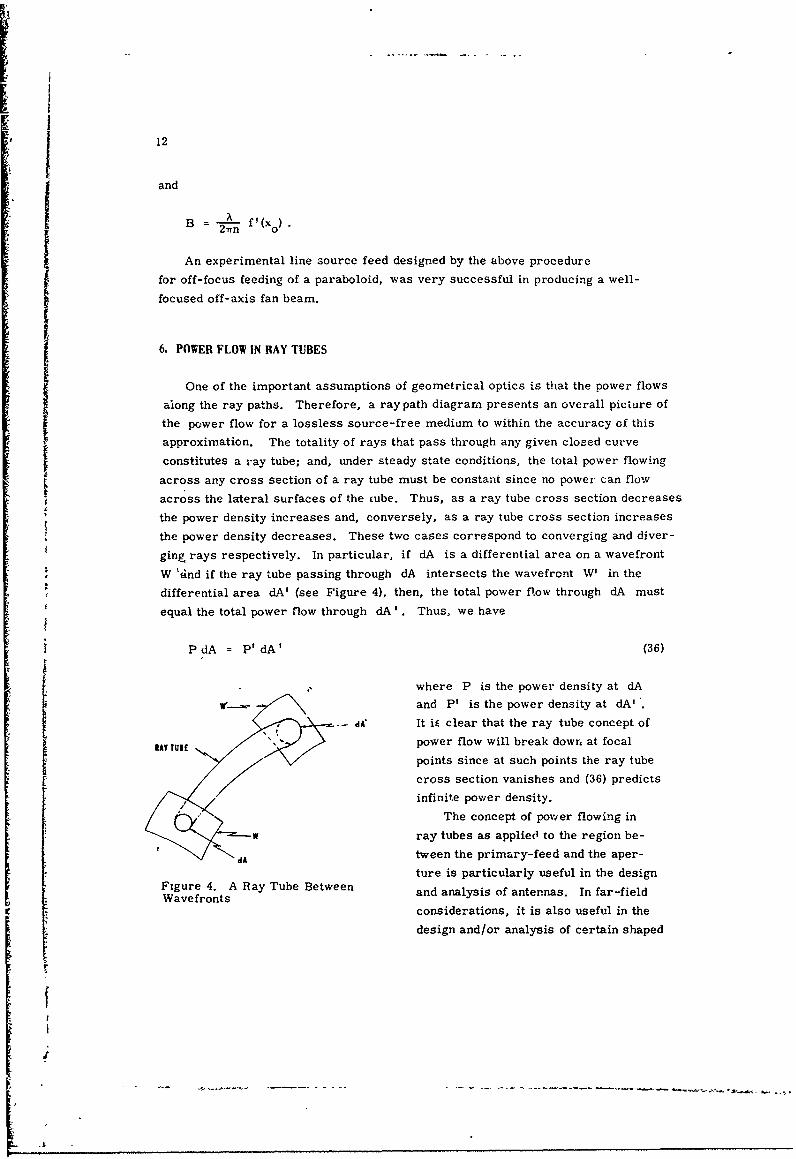
6. POWER FLOW IN RAY TUBES
One of the important assumptions of geometrical optics is that the power flows
along the ray paths. Therefore, a ray path diagram presents an overall picture of
the power flow for a lossless source-free medium to within the accuracy of this
approximation. The totality of rays that pass through any given closed curve
constitutes a ray tube; and, under steady state conditions, the total power flowing
across any cross section of a ray tube must be constant since no power can flow
across the lateral surfaces of the cube. Thus, as a ray tube cross section decreases
the power density increases and, conversely, as a ray tube cross section increases
the power density decreases. These two cases correspond to converging and diver-
ging rays respectively. In particular, if dA is a differential area on a wavefront
W 'find if the ray tube passing through dA intersects the wavefront W' in the
differential area dA' (see Figure 4), then, the total power flow through dA must
equal the total power flow through dA'. Thus, we have
PdA = P'dA' (36)
where P is the power density at dA
w',._.- and P' is the power density at dA'1 . -dA' It iE clear that the ray tube concept ofSRAY TUIE power flow will break down at focal
points since at such points the ray tube
cross section vanishes and (36) predicts
infinite power density.
The concept of power flowing in
w ray tubes as applied to the region be-
dA tween the primary-feed and the aper-ture is particularly useful in the design
Figure 4. A Ray Tube Between and analysis of antennas. In far-fieldWavefronts
considerations, it is also useful in the
design and/or analysis of certain shaped
13
beam and off-focus-fed antenna systems. The ray tube concept finds little appli-
cation in far-field considerations relative to *ell-focused pencil beam systemsii since in such cases the pattern is determined entirely by diffraction.
7.POWER DISTRIBUTION IN THE APERATURE
* In using geometrical optics to investigate antenna aperture-plane power dis-
tributions or to design primary feeds for optimum illumination, the important
quantity furnished by the ray tube concept is an approximation to the relative
power distribution.
To determine the relative power distribution, it is necessary to know the
absolute power distribution to within only an arbitrary multiplicative constant.
Hence, if either the absolute or the relative power distribution is known on a wave-
front W (see Figure 4), then, in using (36) in the form
aAP' t= P (37)
to determine the geometrical optics approximation to the relative power distribu-dAi ~ tion on W' it is necessary to know to within only a multiplicative constant.
For a well-focused, point-source-fed antenna system, the usual procedure for
determining the geometrical optics approximation to the relative power distribution
on the antenna apert- re plane for a given primary feed power, pattern is to first
analyze che system when fed by an isotropic point source. All wavefronts will be
spheres for the isotropic feed and the power density will be constant over any
fixed wavefront W . Also, any differential element of area dA on the wavefront
W will be proportional to the differential 'solid angle dil subtended by dA as
measured4 at the feed. .A general ray trace of the antenna system will determine
the aperture coordinates of the exit ray, as functions of the ray direction coordinates,
as measured at the feed. These relations will determine the area dA' `n the aper-
ture pl.ne W' (assumed to coincide with a wavefront) that corresponds to the dif-
ferential element of area dA in the wavefront W. Since dfl = KdA, where KdQt dA
is a constant, the quantity d is proportional to d and can therefore be used in
the calculation of the relative power distribution on W'. If the primary feed has a
relative power pattern P(0, 4p), where 0 and 0 are the ray direction coordinates,
then the geometrical op+ics approximation to the relative power distribution on the
aperture plane is pro~portional to P(O, 4)) L- , where (in theory) 0 and 0 can
be expressed in terms oi the aperture coordinates.
The geometrical optics approximation to the relative power distribution on the
aperture of a weifo-2oused, line-source-fed cylindrical antenna system can be

14
determined by procedures analogous to those used for the point-source case. It
will be assumed that the relative power pattern of the line-source feed is of the
form P(O, z) = g1 (O)g 2 (z) , where z is the linear coordinate parallel to the feed
line and 0 is the angular coordinate around the feed. Since the antenna system
is cylindrical, all rays from any one point on the feed line remain in a plane nor-
mal to the feed line and, in all such planes, ray trace diagrams are identical.
Thus, power will only flow parallel to these planes and the identity of the ray
trace diagrams guarantees that the relative power distribution on the aperture
plane in the z direction will be proportional to g 2 (z) . This reduces the problem
by one dimension and leads to the consideration of the power flow in a typical plane
normal to the feed line. For a feed isotropic in 0 , the wavefronts are circles and
the power density on these circles iB uniform. If ds is a differential element of
arc length on a fixed wavefront C and if dO is the differential angle at the feed
subtended by ds, then, since C. is a circle, it follows that ds is proportional
to dO . A general ray trace will relate 0 to h , where h is the exit ray aperture
coordinate normal to z ; this relation will determine the differential element oh
in the aperture plane (assumed coincident with a wavefront) that corresponds to dsdOSince ds - K' dO where K' is a constant, it follows that -h is proportional tods
Sand can therefore be used in the calculation of the relative power distribution
on the aperture plane with respect to the h coordinate. For the given feed with
relative power pattern P(9, z) = g1 (0)g 2 (z) , the geometrical optics approxima-
tion to the relative power distribution on the aperture plane is proportional todOg 1(0)g 2 (z) -e, where (in theory) e can be expressed in terms of h.
As a simple example of this procedure applied to a cylindrical system, con-
sider a parabolic cylindeýr reflector of focal length f with its focal line coincident
)y with the z axis. Figure 5 shows a
central plane section of this reflector
with polar coordinates (r, 0) describ-
ing the reflector surface and the linear
do coordinate h designating position in
dh the aperture plane x = 0 . The equa-
tion of the reflector surface in (r, 0)X coordinates is
2f 2-4PARABOLIC r= 1+ cos 0 = f sec2(0 /2).
APERTURE PLANr' CYLINDERSSECTION The primary feed located at F (see
Figure 5) is assumed to radiate uni-
formly in 0 and all rays originatingFigure 5. Central Plane Section of aParabolic Cylinder Antenna at F are assumed to be reflected

15
parallel to and in the direction of the negative x axis. Thus,
h = r sinr = 2ftan(0/2)
dh = f sec 2 (O/2)d9 - rdO
and
dO _ 1dh r
If the given primary feed has a power pattern P(O, z) = g9(0)g2 (z), then, Pa'
the geometrical optics approximation to the relative power distribution on the
aperture normalized at the center of the aperture, is given by
P g 1 (O)g 2 (z) (38)Pa =r gl(0)g2(0) {8
This is certainly a correct result from the geometrical optics standpoint since it
clearly demonstrates that the power spread3 radially, that is, inversely propor-
tional to distance, only in planes normal to the feed line and only over the dis-
tance from the feed to the reflector, that is, over the distance r . After reflec-
tion, the rays are collimated and no more spreading takes place out to the aperture
plane.
8. POWER DISTRIBUTION IN THE FOCAL REGION
In the analysis of an imperfectlyefocused antenna sucn as a spherical reflector
or an off-axis-fed paraboloid, it is frequently desired to obtai.x an estimate of
the relative power distribution along some focal surface or curve in the focal re-
gion. In this case, the ratio of a differential element of surface area of the incoming
plane wavefront to the corresponding differential element of surface area or arc
length in the focal region is an estimate of the relative power distribution on theii appropriate focal surface or curve.
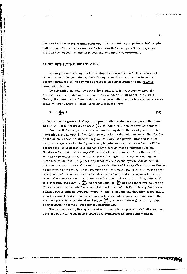
Consider, for example, the problem of determining the power distribution
along the axis of a spherical reflector of radius 'a illuminated by a plane wave
incident along the axial direction (see Figure 6). By symr etry all ray-, after
reflection pass through the reflector axis. The height h of an incident ray and
the coordinate z of the intersection of the corresponding reflected ray with the
reflector axis are related to the angle 0 as follows:
I16
h =asin0
and
a
Z = 2 cos 0
INCOMING PLANE WAVE
SPHERICAL = ed~~~'REFLECTOR =-h
REFLECTOR AXIS dz
REETRCNTER OFCURVATURE
Figure 6. Central Section of a Spherical Reflector
Hence,
.2 =a 2 1_a 2 (39)
4z
The differential area dA generated by re rolving the line segment dh about the
refl-ector axis is
dA = 27rh dh.
All incident rays passing through dA will., after reflection, pass through the
differential line element dz. Thus, the power distribution P along the reflector
axis is
P = B 2r hBdh (0dz 2 hdz (0
where B is a constant. From (39) we have
,•~

17
2h dh = a_4
5h j2z
and (40) becomes
4.BaP r= a
2z3
From (39) we have
lir z = a/2 . (41)
h-.0
This is known as the paraxial focus point. Normalizing the power distribution to
unity at the paraxial focus point the relative power distribution Pr along the re-
flector becomes
3
r z3Z
9. POWER DISTRIBUTION IN THE FAR FIELD
In the use of the ray tube concept to approximate antenna far-field power
patterns, the underlying assumption is that the radiated power after it leaves the
final surface of the antenna flows along ray tubes- not only up to the aperture plan4
but indeed on out into the antenna far field. This assumption is clearly invalid for
well-focused antenna systems, that is, for systems all of whose exit rays are nearly
parallel, since in such cases the pattern is determined entirely by diffraction.
Howevrer, for 3ystens that are not well-focussed in one or in both planes, the ray
tube concept provides a useful approximation to the relative far -field pattern. In anyplane in w -dch *he exit rays are not parallel, the power flow per '.nit directional angle or
per unit solid angle in the exit ray system is determined by the ray-tube concept
as a function of angular direction; this function, after appropriate normalization,
is the geometrical optics approximation to the far-field antenna pattern.
As an example of the use of this far-field spproximation, consider the design
of a iine-source fed cylindrica] reflector to produce a fan beam of prescribed
shape (Spencer, 1943). Let S be the plane of symmetry of this antenna normal
to Lhe line source. The cylindrical geometx y guarantees that all exit rays lying
in planes normal to S are parallel and therefore S will be the plane of the fan

18
beam. It is desired to determine the shape of the reflector cioss section that will
cause ray dispersion in the plane of S appropriate to nroduce the prescribed
fan beam shape. It is assumed that the primary feea pattern Pf(0) and the de-
sired secondary power pattern P(O) are gi'•en. The angles 0 and 0 are mea-sured positive clockwise in the plane of S . (See Figure 7a. ) For practical pur-
poses, the useful portion of the primary fked pattern P f(0) lies between its -10 dBpoints and will be designated by the interval 0 1- 0 n 0 . Generally, the function
12'P(o) vanishes everywhere except within some interval, say 01 1- 0 -2 ' where it
takes on a prescribed ivr~rn. Thus, rays from the line-feed incident on the reflec-tor with inclination angle 0 , 0 1" -0 02 must produce reflected rays ;ith in-
clination angle 0, o 1 ._ 0 OP2 (see Figure 7a).
The problem now is to determine a one-to-one correspondence .;e-ween the
incident and reflected rays-that is, a function o =(0) such that -he reflected
ray system has a power distribution corresponding to P(O). In a differential sec-
tor dO of the incident ray system, the power flow is proportional to Pf(0)dO;
in a corresponding differential sector do of the reflected ray system, the power
flow is proportional to P(4) do. Thus,
• Pf(0) dO = KP (0) do
wht re K is determined by the relation
J 02 o/ 2
It f Pf() dO = K P(O) do01
which is equivalent to requiring equal total powers in the incident and reflected ray
systems. We also require the power in the incident ray system in the interval 0 1
to 0 to be equal to the power in the reflacted ray system in the interval 41 to P.
Thus,
• Pf (0) dO f P( o) d o 420 0
Jrf~1UU ~~I~u4~(42)01
Pf?0) dO P(O) dd1 . f
and this expression determines the required relationship 0 =( 0) .
We now turn to the determination of the equation for the reflector curve. With
the reflector curve denoted by r = r(0) we have from Figure 7b
tt
~ -,. -~- - ~- - - ---- - . '-- --,t-

RI19
tanr rdO
and
+~ 02 2
T• Feeo
FEED
REFLECTOR *Zzzzzz::
Figure 7a
REFLECTOR " '
II- \ FEED
Figure 7b
Figure 7. Shaped-Beam Reflector Geometry in the Plane of Symmetry S
20
Thus,
rdr cot (0..j2 diO cot [-..~~JdO
or
0Iln i)r fcot dB.~! (43)
"vhere
r = r(0).
Equation (43) determines the desired reflector curve to within a radial scale factor
1. Overall physical dimensions, as well as the requirement that the reflector be
in the far field of the feed, establish s range of permissible values for ro .
Generally, the function Pf(0) is given graphically while P(0) may be given
analytically, graphically, or numerically. Therefore, in most cases numerical
integration will be required to determine p - 0(8) from (42) and the resultant
relationship will be expressed in numerical form. Numerical integration will be
reouired to solve (43) for the reflector curve r = r(9).
* i 10. REFLECTION FROM A CONDUCTING SURFACE
In an isotropic homogeneous medium, the geometrical optics approximation
assumes that the energy propagates along the rays as in a planto wave. To within
this approximation, therefore, the field vectors E and H along a ray are relatedI as follows:
S - EXH* E 2S (44b)
S E -- H = E- H = 0 (44c)
where S is the Poynting vector and A is a unit vector in the direction of the ray
(see Figure 8). The magnitude of E (and hence of H and S) is prescribed by
(24).
21
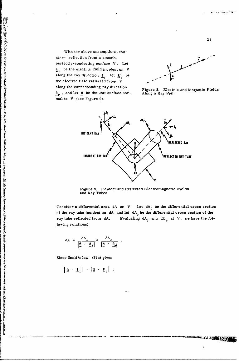
With the above assumptions, con-
sider reflection from a smooth, be irelperfectly-conducting surface V Let E
E i be the electric field incident on Valong the ray direction § . let E rbe
the electric field reflected from V
along the corresponding ray direction Electric and
g and let ft be the unit surface nor- Along a Ray Path
mal to V (see Figure 9).
INCIDENT RAY
to, AREFLECTED RAY
INCIDENT RAY TU E REFLECTED RAY TUBE
Figure 9. Incident and Reflected Electromagnetic Fieldsand Ray Tubes
Consider a differential area dA on V . Let dA. be the differential cross section1
of the ray tube incident on dA and let dAr be the differential cross section of the
ray tube reflected from dA. Evaluaiting dA. and dAr at V, we have the fol-
lowing relations:
dA= dAi dAr
SIsSince Snell • law, (27b) gives
SiI =" "rl
Ii

22
we have
dA. dA1 r
and hence at V
I~ii =I~rl.(45)
The continuity of the tangential electric field at the surface V requires
fiX(Ei+ Er) = 0 (46)
and the plane wave assumption requires
EE. = S E = 0 (47)-i - i -r - r "
It follows from (45) and (46) that at V
fi - (Ei-Er)E 0 (48)
and
E = 2 (l E.) f-E. (49a)-r .. I-1
or
E = (ft E) fi - fAX(E XfA) . (49b); -r . . . . ..--i
The magnetic fields H. and H at V are given by (44a) and (49a) or (49b).1 -r
The above results show that,under the assumptions made,the reflection process
locally at each point of V is equivalent to plane-wave reflection from an infinite
S1conducting plane tangent to V at the point (Silver, 1949). The assumptions of
plane-wave propagation along rays and local reflection behavior as from an infinite
plane lead to useful approximations of the polarization' characteristic3 of reflector-
type antennas.
11. RAY COLLIMATION AND OFF-FOCUS."EEDINGI Consider a focusing system fed by a point source not necessarily located at a
focus point and let a be a unit vector in the direction of the general exit ray.r
I,
23
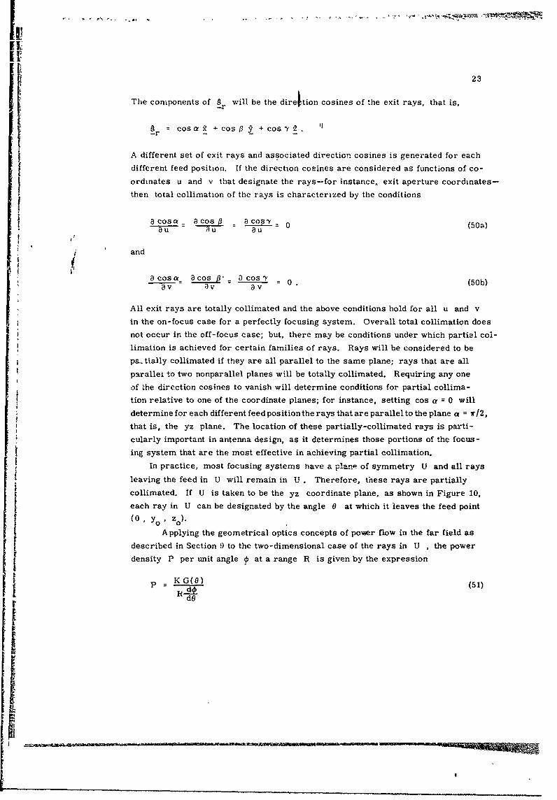
The components of f will be the direltion cosines of 'he exit rays, that is,
gr = cosa +cos + cos 2-r .... +osy~ °
A different set of exit rays and associated direction cosines is generated for each
different feed position. If the direction cosines are considered as functions of co-
ordinates u and v that designate the rays-for instance, exit aperture coordinates-
then total collimation of the rays is characterized by the conditions
a Cosa _ a Cos a cosy (50a)
j ' and
acosCf_ acos 3 cosY(av av av
All exit rays are totally collimated and the above conditions hold for all u and v
in the on-focus case for a perfectly focusing system. Overall total collimation does
not occur in the off-focus case; but, there may be conditions under which partial col-
limation is achieved for certain families of rays. Rays will be considered to be
pa- tially collimated if they are all parallel to the same plane; rays that are all
parallei to two nonparallel planes will be totally collimated. Requiring any one
of the direction cosines to vanish will determine conditions for partial collima-
tion relative to one of the coordinate planes; for instance, setting cos a = 0 will
determine for each different feed position the rays that are parallel to the plane a = i/2,
that is, the yz plane. The location of these partially-collimated rays is parti-
cularly important in antenna design, as it determines those portions of the focus-
ing system that are the most effective in achieving partial collimation.
In practice, most focusing systems nave a plane of symmetry U and all rays
leaving the feed in U will remain in U . Therefore, these rays are partially
collimated. If U is taken to be the yz coordinate plane, as shown in Figure 10,each ray in U can be designated by the angle 0 at which it leaves the feed point
(0 , Yo ' z0 ).
Applying the geometrical optics concepts of pover flow in the far field as
described in Section 9 to the two-dimensional case of the rays in U , the power
density P per unit angle 4 at a range R is given by the expression
p K G(O) (51)
dO

I24
where K is a constant and G(O) is the
EXIT RAY feed power pattern iM U. This expres-
sion gives a rough estimate of the far-
- field power pattern in the plane of U,
provided - / 0 . If the exit ray at
- angle k = 00 corresponds to the rayz leaving the feed at angle 0 = 0 the
00
(01 Y1 ZO) condition
FCSNG SYSTE EDPON - =0 (52)
Figure 10. Section of FocusingSystem in the Plane of Symmetry U determines the feed position that will
produce local collimation of the rays in
U that are in the neighborhood of the exit ray in the direction k = 0o. Under these conditions,
geometrical optics predicts an infinite singularlity in the far-field pattern, which mayR:E • be interpreted as a power pattern maximum in the direction q5 = €o ; but, relative
magnitudes obviously cannot be determined without, the use of diffraction.
12. CONGRUENCES AND THE EQUAL PATH LENGTH LAW
A two-parameter family of curves constitutes what is known in differential
geometry as a congruence. The member curves of a congruence are called genera-
tors. If these generators are straight lines, the congruence is denoted as recti-
linear. Furthermore, if there exists a surface that is normal to all the generators,
the congruence is designated as normal. Thus, in a homogeneous isotropic medium,
the normals to a wavefront-that is, the rays themselves--constitute a normal
rectilinear congruence. It can also be shown that a normal rectilinear congruence
possesses not just one normal surface but a whole family of normal surfaces
-- (Eisenhart, 1960, p. 393); these surfaces, of course, correspond to wavefronts
of the corresponding ray congruence.
Rectilinear congruences are not necessarily normal and, therefore, the Theorem
of Malus (Eis.enhart, 1960, p. 403) is of fundamental importance in ray-path analysis.
9 This theorem states that if a family of rays, initially a normal rectilinear con-
gruence, is reflected or refracted any number of times by successive homogeneous
isotropic media, the rays will continue to constitute a normal rectilinear congruence.
Therefore, for antenna systems satisfying the condition' of this theorem, both
incident and exit wavefronts are guaranteed to exist. Since wavefronts are equi-
phase surfaces, it follows that between any two specifir'wavefronts the optical path
lengths along all ray paths must be equal; this is a mos4 important result and forms
Ii
I!

25
the basis of the equal path length law and the associated design procedures appli-
cable to reflection and ref'-action.
Consider the problem of designing a reflector R passing through a given point
P0 that will reflect a given incident wavefront W into a desired reflected wave-
f ont W' (see Figure 11). The desired reflector surface is given by the locus of
points P determined by the condition
d+ d' = d + d' (53)0 0
POPIt is very important to note here that Snell's
law of reflection will automatically be satis-fied at the reflector surface. In the corres- N d. W1
ponding refraction problem, it is desired to
determine the boundary surface S between W
two different homogeneous media passing
through a given point P0 such that a given Figure 11. Wavefronts and Rays for
incident wavefront W is converted into a Reflection From a Curved Surface
desired refracted wavefront WI (see
Figure 12). In this case, the surface S is the locus of points P determined by
the condition
nd+ n'd' = nd + n'd' , (54)0 0
and Snell's law of refraction will automatically be satisfied at the interface.
d d
W
INDEX OF INDEX OFREFRACTION n REFRACTION nt
Figure 12. Wavefronts and Rays for RefractionThrough a Curved Interface
In both of the above-mentioned procedures, it is necessary that the reflecting
or refracting surface be located in a region where through each point there passes
not more than one ray of the incident ray congruence and not more than one ray of
the reflected or refracted ray congruence. If this restriction is violated, it will
11'1 ýRgwm

26
not be possible to design a reflecting or refracting surface that satisfies the equal
path length requirement along all rays.
As an example of the application of the equal path length law, consider the
design of a reflector to correct for the inherent spherical aberration of a spherical
reflector (Holt and Bouche, 1964). Let the radius of curvature of the spherical
reflector be %" and let the center of curvature be the origin. With the x axis as
the reflector axis, an incoming plane wave along the x axis is assumed; the yz
plane is the reference wavefront. The spherical reflector, the corrector, and theassociated ray system are all radially symmetric about the reflector axis; there-fore, all sections in planes through the x axis are the same (see Figure 13).
y* GENERAL RAY CORRECTOR
REFLECTORCAXI
CENTER OF CURVATURE 2.
f8
0~~~ V'0. (b)0
REFERENCE WAVEFRONT 0
SPHERP",•L REFLECTOR
Figure 13. Spherical Reflector Section in the xy Plane
To fix the solution, let V with coordinates (a, 0) be the vertex of the reflec-
tor, let V' with coordinates (a', 0), a 1_- a/2, be the vertex of the corrector, and
let F with coordinates (b, 0), b >a', be the final focus point. The condition
a'-< a/2 guarantees that the corrector will lie in a repion where only one ray ofthe incident ray congruence and only one ray of the reflected ray congruence will
pass through each point.
Applying the equal path length law to the general ray QPP'F and the axial
ray GVV'F , we have
ýP + TPPI + PFF -5-1:1+ T7• + V'F
or
a(cos 0)+ + 2x'-x +y y) 2 + 2 a+b-2a

27
where
x = acos 0 , y a sin 0 , and y'- y = (x'- x) tan 20
Solving for x' and y', we obtain-
x1 = acos 0 -n2 cos2 0 -4a(a-a') cose- (a 2 + b 2) +(2a+b-2a') 2J (2 cos 2 e - 1)
4(b cos 29 - a cos 0 - a' + a)
(55a)
y, = + (2x' cos_0 - a)(sin 0) (55b)(2 cos 0- 1)
These are thr coordinates of the corrector surface in terms of the parameter 0
Provided a' and b lie in the indicated ranges, the answer given above is valid
and unique. (The + sign for the y' value merely indicates symmetry with respect
to the x axis.)
13. FOCAL SURFACES
Let us consider a wavefront W and its associated ray congruence. Let P be
a point on W and let PN be a line segment normal to W (see Figure 14). If CR
is a line of curvature of W with p = R 1 at P (see Appendix A), then in the near
vicinity of P the normals to W along C R appear to converge to a point Q 1 on
PN on the concave side of C at a distance R from W. Similarly, if CR 2C1l dsacR 1 fro W.
is a line of curvature with p = R 2 at P , then in the near vicinity of P the normalsto W along CR 2 appear to convergc to a point Q 2 on PN op the concave side of
CR 2 at a distance R 2 from W . Thus, to each point P on the wavefront W
there is assoc:ated a unique pair of points Q 1 and Q2 on the normal line PN.
These points are called focal points; in general, the totality of all these points
constitutes two surfaces which are called focal surfaces or caustics. These surfaces
may de,,enerate into such forms as a single surface, a surface and a curve, a single
curve, or a single point. It is important to note here that the focal surfaces are the
same for all wavefronts of a particular ray congruence.
The focal surfaces cin also be described in terms of the envelopes of certain
families of rays. A family in this case consists of the totality of rays passing
throgh a particular line of curvature of W , - ruled surface so constituted is
known as a principal surface. Two typical families are shown in Figure 14. It is
characteristic of each family that it envelopes a curve in space (SI and S2 in
Figure 14). It can be shown that each of these spaze curves lies on a focal surface;

28
thus, the rays of a congruence are tangent to the focal surfaces ilong these envelope
curves. The totality of all the envelope curves constitutes the focal surfaces.
In any specific problem regarding
the determination of focal surfaces,
either a ray congruence or a wavefrontwill generally be given. Since all wave-
fronts can be determined from the ray
"congruence and vice-versa, these two
forms of tne statement of the problem
. •I• are entirely equivalent. In actuallycarrying out the computations to obtain' ' I I
/ the focal surfaces, however, the form
E P 1 al of the statement of the problem and theJWauf s1 --- , / functions involved will determine the
best solution procedure. Two proce-
dures will be given here-one particularly
"'iii applicable when the wavef.ont is given
and the other applicable when the ray
EN•VELOPE s2 congruence is given.Consider the problem of determining
the focal surfaces given a wavefront W
in the form
N P = x(u,v) ý+ y(u v)j+ z(uv) z
Figure 14. Ray Paths in the Prin- where P is a vector from the origin tocipal Planes a point P on W and u and v are
curvilinear coordinate3 on W. The nor-
mal vector to W aL P is given by
N = PXP ,
where the subscripts denote partial differentiation and the expression is evaluatedat P. To each of the two lines of curvature CR and C through P there
corresponds a principal unit normal vector. These unit vectbrs will be in the
directien of N or -N, whichever points to the concave side of the correspond-
ing line of curvature. Let nI be the principal unit normal for CR and let
be the princiý -1 unit normal for C R2. The principal normal radii of curvature
R1 and R2 it W at P are given by the solutions to the quadratic equation
29
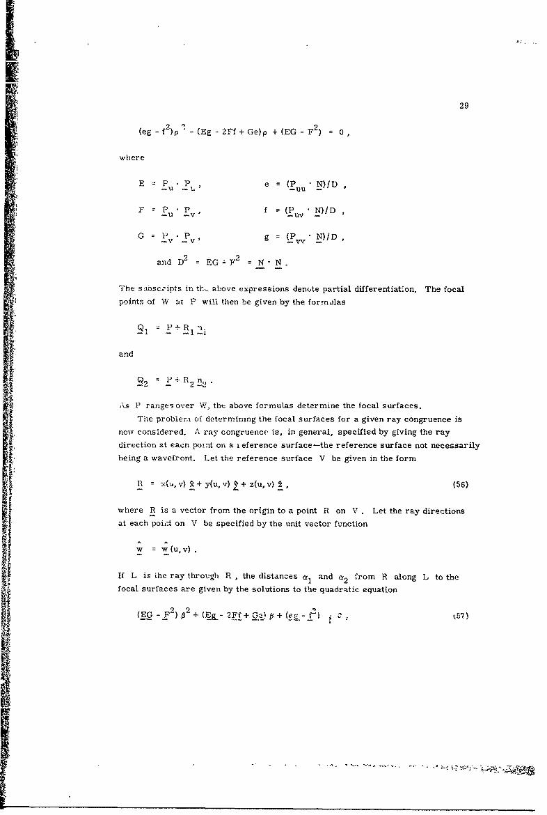
(eg- f 2 )p - (Eg - 2Ff + Ge)p + (EG -F 2 ) 0
where
E P u P' e = (Puu N)!D
F =P u P v f = (P uv N)/D
G P P g = (P, N)/D,
and D 2 EG-F 2 = N" N
The sdbsczipts in th. above expressions denote partial differentiation. The focal
points of W at P will then be given by the formulas
•I: q• = P+R 1~.
and
2 = P+ R 2-n.
As P ranges over W, the above formulas determine the focal surfaces.The problem of determining the focal surfaces for a given ray congruence is
now considered. A ray congruence is, in general, specified by giving the ray
direction at eacr. point on a eference surface-the reference surface not necessarily
being a wavefront. Let the reference surface V be given in the form
R n x"', v)R+y(u,v) +z(u,v)2, (56)
where R is a vector from the origin to a point R on V . Let the ray directionsat each poi t on V be specified by the unit vector function
w = w_(u, v) .
If L is the ray through R , the distances ct and a 2 from R along L to the
focal surfaces are given by the solutions to the quadratic equation
(EG -F2)• + (qg_ - 2 Ff+ .G': ! + (e g.-_k57)

30
where
E = Wu wu, e Ru u
F = w fkR wk = (58)u vW , V g-V
-f v -V"v "v
with the subscripts denoting partial differentiation. The focal points on L will be
Q1 =R+ flw (59n,)
and
Q2 = 2f2 (.59b)
As R ranges over V, the above formulas determine the focal surfaces.
Consider, for example, the determination of the focal surfaces or c/,ustics
produced when a paraboloid of revolution receives off-axis (Parke Mathematical
Laboratories, Study No. 3, 1952). Let the paraboloid of focal length f be located
with its vertex at (0, 0, f) and its focus point at the origin and let the' incoming rays
be in the direction
-. = - I +Cny+cosa Y
as shown in Figure 15. The paraboloid
surface will be considered the reference
surface and in terms of the parameters
r , P its equation is
xX x r cos n
zz 4f2 - r2x• • = ~4f '(0
Applying Snell's law, (27c), at the re-PARABOLOID .2 y2
. -4f(Z-I) flector surface leads to the reflected
Figure 15. Geometry of Paraboloid ray directionsReceivAng a Plane Wave Off-t~xis
Ii
rij
Ii•
31
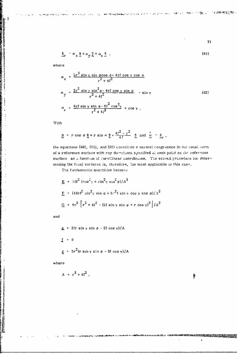
!r x- + +az , (61)
S~where
a =a2r2 siny sir. Ocos d- 4rf cos y cos p
x ~ 22x r + 4f
sn2r2 y sin2 - 4rf cos - sin 6ry r + 4f2 sin -y (62).
a 4rf sin.T sin 0-.8f2 cos2+Co -
r + 42
Rith
r cs 2+ rsif2 .2 r2R = co € t~r in ,92 , and w -- A
the equations (60), (F,1,:, and ,2) -onti•t -ate a normal congruence in the •suai ;orm
of a reference surface with ray dir-ct_,ons specified -,ý each poiht on Ch1 reference
surface as . funct;,,n of ?urvtinear coordintces. The seccnad prc~cedure 1o1 Jeter-
mining the focal curfaces ;s, th-refore, the moT t applicable in this case.
T:'c fundame:,tai ,uacn.ties becorm,.9
i2f2cos•y + .2n 2 2E = iff krOS + sn -y sin Oj
F = (16rf 2 3in 2 %- sin 0 + 8:'2f sin -v cos - cos <,)/A2
G = 4r 2 [r2+4f2 -(2fsiny sin 9-) r cos:) 2 /A 2
and
_= 2(r siny sin -2f cosy)/A
f =0
9
g_ = 2r(r sin-y sin • - 2f cos y)/A
where
A = r2 +4f
32
Substituting into (57) Rnd solving f,' p (with much labor), we obtain
t2 + sin 2Y + 8f2Ml = 2 (2f cos7y - r sin - sin d,'
-4rf si. rcosy sin 0 ± (r2 + 4?) sinn7y
(rr2 - 4f2 ) cosy +4rf ein ysin Pj2S~r2 + 462
Equations (59a -nd b) then give the focal surfaces in terms of the curvilinear coor-
dinates (r, :).E In terms of cartesian coordinates (x, y, z) on the paraboloid surface, the equa-
tions for the focal surfaces become
+-x--, y 2f - z) sin-Y
(+ z-B 1 2fo- y ) cos, (63)
~z-2f 2cos y- ysiny
where
B 2f- z+cos-y (z cos y, - y sin -) +(2f-z)s 1- cos -ysinzSf All 2f-z
(64)Calculations for the particular case y = 200 have been carried out ana the
focal surfaces calculated and constructed (Parke Mathematical Laboratories,
Report No. 1, 1952). Figures 16a, b, and c show the focal surfaces individually
"and sup'.rimposed.
"14. GENERA.. COMMENTS ON FOCAL SURFACES
The normals to a wavefron- through a line of curvature tend, in general, to
focus on one or the other of the two focal surfaces. The physical extent of the
focal surfaces is, therefore, a measure of the focusing ability of the ray congruence
associated with the wavefront. If the focal surfaces are extensive and far apart,
the focusing is poor; ff the focal surfaces are small and closely spaced, the focus-
ing is good. If the focal surfaces degenerate to a line or to a point, the focusing
may be considered as perfect. dependJing or, the application.

33
P~
4 Figure 16a. Paraboloid and One Focal Figure 16b. Parapoloid and a SecondSurface Focal Surface
F
Figure 16c. Paraboloid and Composite of Focal Surfaces
Figure 16. F'.•-l Surfaces of a Paraboloid Receiving a Plane Wave 200 Off-Axis

If it is desired to receive the energy of a converging wavefront by means of a
point source, the optimum position for the point source will, in general, be either
on one of the two focal surfaces or between them. Regions where the focal surfaces
are close together or intersect generally have high energy density. Degenerz.te
j focal surfaces are also regions of high energy density. Since 6vcry ray is tangent
to each of the two focal surfaces, the total energy in the wavefront can be collected
p by locating properly-phafsed receivers on one or the other or on parts of both of the
focal surfaces.
For purposes of low side lobes in a focusing system there generally is
a power taper across the wavefront whether considered in the focal region
or in the aperture plane. This taper places greater importance on the rays through
the center of a focusing system-that is, rays near the chief ray-than on rays nearthe edge of the system.
In general, the existence of two distinct focal surfaces in the focal region of a
focusing system indicates the presence of astigmatism. For each different direc-
tion of incoming energy, the separation of the focal points " I and Q2 (see Figure 14)I along the chief ray is particularly important because it is a measure of the astigma-
tism in a region of high power density. In most one-dimensional scanning systems,
the plane of scan is a-plane of symmetry of the system and also a principal surface
,& of all ray congruences in the focal region. The other principal surfaces for all
chief rays in the plane of scan will be normal to the plane of scan, As the direction
of the incoming energy changes in the plane of scan, the two focal points associated
* with the chief ray describe two curves. Rays in the plane of scan near each chief
ray will focus on one of these curves, known as the T (tangential) curve, while rays
near the chief ray but in a plane normal to the plane of scan will focus on the other
curve, known as the S (sagittal) curve. The separation of the S and T curves
is thus a measure of the astigmatism along the chief ray for directions of incoming
energy in the plane of scan and hence is an indication of the scanning capability of
the system. if the S and T curves are close together, beam scanning can be ac-
complished by point-source feeding along a mean curve between the two. If multi-
ple beams broad in the plane of scan but narrow in the other dimension are de-
sired then point-source feeding along the S curve will produce the desired result.
If multiple beams narrow in the plane of scan but broad in the other dimension
are desiredthen point-source feeding along the T curve will produce the desired
result.

•5)
References
Eisenhart, L. P. (1960) A Treatise on the Differential Geometry of Curves andSurface-L, Dover Prblications, New York.
Hildebrand, F. B. (1949) Advanced Calculus for Engineers, Prentice-Hall, NewYork, p. 294.
Holt, F.S., and Bouche, E.L. (1964) A Gregorian corrector for spherical reflec-tors, IEEE Trans. Antennas and Propagation, AP-l2(No. 1):44-47.
Kline, M., and Kay, I. (1965) Electromagnetic theory and geometrical optics,Interscience, New York,
Kouyoumjian, R. G. (1965) Asymptotic high-frequency methods, Proc. IEEE53:864-87 6.
Luneburg, R. K. (1944) Mathematical Theory of Optics, Brown University Notes,Providence, Rhode Island.
Parke Mathematical Laboratories, Inc. (1952) Calculation of the Caustic (Focal)Surface "'hen the Reflecting Surface is a Paraboloid of Revolution and the In-cming Rays are Parallel, Study No. 3, Contract AF19(122)-484.
Parke Mathematical Laborato-ies, i,-c. (,1952) Calculation of Caustic Surface ofa Paraboloid of Revolution for an Incoming Plane Wave of Twenty-DegreesIncidence, Report No. 1, Contract AF19(604)-263.
Silver, S. (1949) Microwave Antenna Theory and Design, McGraw-Hill, New York,pp, 132-134.
Sletten, C. J. et al. (1958) Corrective line sources for paraboloids, IRE Trans. PGAPAP-6(No. 3-250-251.
Spencer, R.C. (1943).§ynthesis of Microwave Diffraction Patterns with Appli-
satiQns to csc2 Patterns, MIT Radiation Laboratory Report No. 54-24.Procedure described here due to L. J. Chu.
ffi

Al
4Appendix A
Principal Normal Radii of Curvature, Principal Directlons, Principal PNanes,and Lines of Curvature
Let P be a point on a surface W and let PN be a line segment normal to W
at P (see Figure Al). Each normal plane through PN intersects W in a curve
"C and each curve C has a unique radius of curvature p at P. In general, for
each point P there is also a unique position of the normal plane, such that thek intersection curve C = C 1 has a radius of curvature p = R at P that is maximum
(see Figure A2). Similarly, there is a unique position of the normal plane, such that the
Sthe intersection curve C = C 2 has a radius of curvature p = R2 that is minimum.
These extreme values R and R are called the principal normal radii of curva-
ture of W at P; the directions of C 1 and C 2 at P are knowr is the principal direc-
tions of W at P; and the normal planes whose intersect with WV produce C1
and C2 are called the principal planes of W at P , A ve on W that at each
point has a direction corresponding to a principal direction of W at tnat point is
known as a line of curvature of W. It can be shown that the principal planes at each
point are mutually orthogonal and hence the two families of lines of curvature form
an orthogonal curvilinear coordinate system on W
(
*1.

p A2
" P
Figure Al. Surface vith NormalI pLine and Normal Plane
I
I-
iH
C,
• Figure A2. Principal Normal Radiiof Cu-rvature and Principal Directions CIi 2i at a Point on a Surface
R2 R

IB
B1
Appendix BGeometrical Optics Power Flow in a Source Free, Nonconducting,
Isotropic, Homogeneous Medium
The ray paths for this case are straight line3 'see Section 2). In Figure B1, P
is a point on a wavefront W, P I is the corresponding point on the wavefront WI,
and d is the distance from P to P.
The differential element of area dA on , C,
"W is centered at P and the correspond- dA
ing element dA' is determined by the
intersection of the ray tube through dA
with the wavefront W' . Tne curves
C 1 and C2 through P are lines of d .
curvature of W and hence are mutually
orthogonal (see Appendix A). The cor- p C2
responding curves CI al C2 in W' Ic
are also orthogonal lines of curvature.
If the principal normal radii of curva-
ture of W at P are R 1 and R 2 and
the centers of curvature are located as
shown in Figure B1, the principal normal
radii of curvature of W' at PI are PRINCIPAL NORMAL CENTERSS~OF CURVATURE
R{ =R1 +d and R = R 2 + d. Thus,dA is proportional to R1 R and dA'1 2is proportional to R 1 R1 = (R 1 +d)(R 2 +d)
If S is the power density at P and if Figure B1. Geometrical Optics
S is the power density at P ,Power Flow
Si5'i h oe est tP
I , .................... . .. . . .... . . ..... . . . .. ...... .. .. ......................................................

B2
(36) becomes
SdA S' dA'
or
= dA S (R1+ + d) (BI)
The Gaussian curvature K of WI at P' is defined to be
1 -- I-__ _ 1K 1- 111 - (RI+ d)(R2 +d) (B2)
1and hence is a function of d . Since K(0) =RI1 R2 , we can write
S, S SKI, (33•:u) (B3)VqU)
This equation relates the power density S? at the point PI on a ray to the power
density S at a reference point P. The power flow so expressed is equivalent to
the pr,-, er flow implied by the field intensity relation (26).

Unclassifiec"Security Classfic&-ion
COCLWMENT cOWTRO. DATA. -R&(Sec';ity cla.stiscation of ttle, b0V of G ,...rt ae, t desa; aneo:,aon ,at.,: De ensercd .wAn Me overrli isort is cciasiftidi.
1. ORIGINATINI ACTIVITY (.oq',y" iJ aw r) " , RrPOiT TSCUhITY CLAJS'FICAT Ot
Air Force Cambridge lheseareh Laboratories (CR.- f UncJassifiedL. G. Hanscom FieldBedford, Massachusetts 01730
1 REPORT TITLE
APPLICATION OF GEOMETRiCAL OPTICS TO THE DESIGN AND ANALYSISOF MICROWAVE ANTENNAS
4 DESCRIPTIVE NOTtS (Te ofrept adnlusdve da"cc)Scientific. Interim.
F. Sheppard Holt
B REPORT DATE I&* TOTAL NO. OF PAGC$ j'7 NO. OF REFS
September 1?67 45 'I_ 12Ia. CONTRACT CR GRANT NO. PG. ORIGINATOWS REPORT $UMB•EW')
AFCRL-67 -05011b. PROJECT. TASK. WORK UNIT NOS. 5635-02-01
c. 000 ELEMENT 6144501F ,&A oýS) (Aslly ode M AM a be
d. 000 SUSELEMENT 681305
10. DISTRIBUTION STATEMENT J _
Distribution of this dozument is unlimited. It may be released ýb theClearinghouse, Department of Commerce, for sale'to he gertral publ;.,z.
11. SUPPLEMENTARY MOTESt SPOS'rNN ýAC:WISAir ForX &b• id•R ese.x•rchTECH ... . I Laboratot (CR
TECH, OTHER L. G. Hansc' n Field,- edford, M achuses ,1730
1S. ABSTAACT /// - r "-
The basic concepts of geometrical optics together * h'theadditiona!assumption that lead to the'Igeometrical optics ap aao•-, are describedhere. The eikonal equation is derived and the relationship of exact electro-magnetic theory in the limit as" 7 -* X to geomet-icaldpH is made evident.The application of the "geometricif1optics approximati' tophase analysisand synthesis is described and an example of aynthesis presented. Theconcept of power flow in ray tubes is used to obtain appr rximations to powerdistributions in the antenna aperture, in the focal regih, and in the far field.Ray analysis is used to determine those feed locations G the focal regionthat will most nearly collimate the far-field rays that l1t in certain desirableplanes. The Theorem of Malus is used to formulate the equal path length lawand applications are given. Focal surfaces (or caustics) elativ.e to a recti-linear congruence are defined and then used to present a,geometsical opti€sdescription of the focal region. The -quations of tne fr.cql surfaces of a para-boloid receiving a plane wave 20" off-axis are calculated and photographs ofthree-dimensional models of the focal surfaces are shown.
DDFR`1473NV aUnclissified
Secuiry Cassificadow

Unclassified
14. SKEY WOCA S LINK A LINK T LINK C
ROLE WT ROLE ROLE WT
M crowave OpticsGeometrical Optics
tntenna Design and Analysis
I *I,
ii i"
S~UnclassifiedkSec-ity Cssification
t