application and integration guide - altronic, llc aig...application and integration guide upgrade...
TRANSCRIPT

Application and Integration GuideUPGRADE FOR CATERPILLAR G3500 SI/EIS
Form CAT-3500-UPG AIG 7-12

CAT-3500-UPG AIG 7-12 All rights reserved © ALTRONIC, LLC 2012 2
1.0 SYSTEM DESCRIPTION1.1 The retrofit ignition/control system for Caterpillar G3500 SI/EIS is a simple, pre-
engineered solution that allows operators of legacy G3500 engines equipped with SI or EIS ignition systems an upgrade path to industry-standard, cost-effective Altronic ignition and control components. This package enables operators of these engines to enjoy greater flexibility in the control of their equipment, and ensures future parts availability and upgrade options through Altronic and it’s global Distributor network. The key components of this upgrade include the CPU-95 ignition, the DET-1600 detonation detection system, and the DSG-1682DUPS dual-setpoint gauge.
1.2 The Altronic CPU-95, DC-powered ignition system is a microprocessor-based capacitor discharge system designed for application on natural gas fueled engines. The system features crankshaft-triggered timing accuracy and the capability to vary timing electronically by several means, including an external 4-20mA control signal. The system is field-programmable and offers a variety of advanced control methods, primary and spark diagnostics, self-diagnostics, serial communications and engine protection features. The system consists of two main parts: an engine-mounted Ignition Module and a user interface Display Module.
1.3 The Altronic DET-1600 Detonation Sensing Monitor is a 32-bit microprocessor- based electronic instrument that detects and eliminates detonation on natural
gas-fueled engines before damage occurs. Industry-standard low cost broadband piezoelectric vibration sensors, mounted on the engine, are used to transform the vibrations caused by detonation into electrical signals which are then evaluated by the DET-1600. The Detonation Sensing Monitor uses the sensors to measure the combustion intensity of each cylinder in a user-configured time window. The detonation signals are filtered by programmable filters and then sent to the microprocessor for further processing and evaluation. This process is repeated for every cylinder on a cycle-by-cycle basis. The resulting two reference numbers, one for detonation intensity and the other for the lack of a combustion process, or misfire, are displayed on a LCD display. These reference numbers are used to control two output switches, typically one for load control and the other for shutdown, and a 4-20mA current loop used to retard ignition timing.
1.4 The Altronic DSG-1682DUPS Digital Bargraph Setpoint Gauge is a two-channel electronic instrument used to measure two variables and to output a 4-20mA signal proportional to the differential. Although the gauge is intended to measure pressure, temperature, or vibration, virtually any signal in the range of 0-5V, 0.5-4.5V, or 0-20mA can be used. A backlit, 128 x 64 graphic LCD screen displays numeric values, engineering units, labels, and the state of the outputs. A front-mount membrane keypad serves as the user interface.
2.0 OVERVIEW AND THEORY OF OPERATION2.1 The retrofit ignition and control system for the Caterpillar G3500 SI/EIS equipped
engines allows for the G3500 engine to operate with standard Altronic ignition and control equipment, giving the user the ability to adjust engine operating parameters as the application requires. The system monitors key parameters of engine operation and adjusts the ignition timing according to a multi-point, user-defined map of ignition timing values. These points include:
n Ignition Timing vs. Engine Speedn Ignition Timing vs. Air Manifold Pressuren Ignition Timing vs. Engine Detonation
2.2 The ignition timing vs. engine speed curve is a piece-wise linear function that is programmed into the CPU-95 output module. This function calculates the global ignition timing retard based on the current engine speed. This function forms one-half of the basic, open-loop ignition timing map used in the G3500 retrofit system.
2.3 The ignition timing vs. air manifold pressure curve is a linear function that is programmed into the CPU-95 and DSG-1682DUPS gauges. For most common applications it is assumed that the air manifold pressure is closely tied to the
WARNING: This document is intended as a supplement to aid in the application of products for a specific use, it is not a replacement for OEM, Altronic, or other installation and operating manuals. Always ensure to consult all other applicable installation and operating manuals prior to use of this guide.
WARNING: Advanced product applications such as those described herein assume that the installing technician has the requisite experience, knowledge, and equipment to perform the task in a manner which leads to safe operation.
CAT-3500-UPG AIG 7-12 All rights reserved © ALTRONIC, LLC 2012 3
engine power output, making it a good indication of load. This relationship is based on the premise that higher air manifold pressure results in a larger mass of air and fuel in the combustion chamber. This function forms the other half of the basic, open-loop ignition timing map used in the G3500 retrofit system.
2.4 The ignition timing vs. engine detonation curve is a linear function that is programmed into the DSG-1682DUPS gauge. It is implemented as an offset to the air manifold pressure curve, allowing for varying amounts of detonation-based ignition timing authority, depending on the particular application. The detonation function is essentially a closed-loop feedback from the engine to adjust the ignition timing based on current combustion characteristics. The DET-1600 is capable of taking additional action in the case of engine detonation using onboard output switches—this may include load control and ultimately, shutdown, depending on the needs of the application.
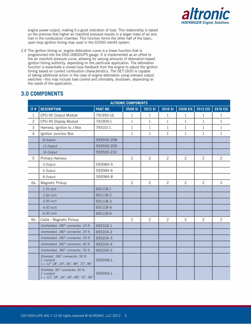
3.0 COMPONENTSALTRONIC COMPONENTS
IT # DESCRIPTION PART NO. 3508 SI 3512 SI 3516 SI 3508 EIS 3512 EIS 3516 EIS
1 CPU-95 Output Module 791950-16 1 1 1 1 1 1
2 CPU-95 Display Module 791909-1 1 1 1 1 1 1
3 Harness, Ignition to J-Box 793101-L 1 1 1 1 1 1
4 Ignition Junction Box 1 1 1 1 1 1
8 Output 593500-208
12 Output 593500-209
16 Output 593500-210
5 Primary Harness 2 2 2 2 2 2
4 Output 593084-4
6 Output 593084-6
8 Output 593084-8
6a Magnetic Pickup 2 2 2 2 2 2
1.75 inch 691118-1
2.50 inch 691118-2
3.00 inch 691118-3
4.50 inch 691118-4
6.00 inch 691118-6
6b Cable - Magnetic Pickup 2 2 2 2 2 2
Unshielded, 180° connector, 10 ft. 693104-1
Unshielded, 180° connector, 20 ft. 693104-2
Unshielded, 180° connector, 30 ft. 693104-3
Unshielded, 180° connector, 40 ft. 693104-4
Unshielded, 180° connector, 50 ft. 693104-5
Shielded, 180° connector, 50 ft.L" conduitL = 12" 18", 24", 36", 48", 72", 96"
593048-L
Shielded, 90° connector, 50 ft.L" conduitL = 12", 18", 24", 36", 48", 72", 96"
593054-L

CAT-3500-UPG AIG 7-12 All rights reserved © ALTRONIC, LLC 2012 4
ALTRONIC COMPONENTS
IT # DESCRIPTION PART NO. 3508 SI 3512 SI 3516 SI 3508 EIS 3512 EIS 3516 EIS
7a Trigger Magnet 1 1 1 1 1 1
3/4" diameter x 8mm thread(max. rotating circle is 15" diameter) 260604
3/4" hex x 8mm thread(max. rotating circle is 15" diameter) 260605
3/8" hex x 8mm thread(max. rotating circle is 6" diameter) 720002
Trigger Magnet disc, 5" diameter 790111-1
7b Hall-Effect Pickup 1 1 1 1 1 1
5/8"-18 thread x 2.5"threaded body length 591014-2
5/8"-18 thread x 4.0"threaded body length 591014-4
7c Cable - Hall-Effect Pickup 1 1 1 1 1 1
Unshielded, 90° connector48" conduit, 50 ft. cable 593050
Shielded, 180° connector, 25 ft.L" conduitL = 6", 12", 18", 24", 36", 48", 72", 96"
593052-L
Shielded, 90° connector, 25 ft.L" conduitL = 6", 12", 18", 24", 36", 48", 72", 96"
593057-L
8 Flange Ignition Coils 591018 X X X 8 12 16
9a DET-1600 Control DET-1600 1 1 1 1 1 1
9b Vibration Sensor 615107 8 12 16 8 12 16
10 Cable: #1 Cyl and “G” 593052-L 2 2 2 2 2 2
11 Sensor Harness 1 1 1 1 1 1
4 Input 593083-4
6 Input 593083-6
8 Input 593083-8
12a DSG-1682DUPSDigital Setpoint Gauge DSG-1682DUPS 1 1 1 1 1 1
12b Pressure Transducer, 0-50 psia 691204-50 1 1 1 1 1 1
12c Cable Assembly 693008-50 1 1 1 1 1 1
3.1 CPU-95 Output Module – See forms CPU-95 AL, CPU-95 II, CPU-95 OI, CPU-95 PI, and CPU-95 SI for complete explanation.
3.2 CPU-95 Display Module – See forms CPU-95 AL, CPU-95 II, CPU-95 OI-ED, and for complete explanation.
3.3 Ignition to Junction-box Harness – Dual-connector, shielded, liquid-tite wiring harness that connects from the CPU-95 output module to the ignition junction box. Length of this harness should be kept to minimum required for on-engine installation. See form EZRail II for additional information.
3.4 Ignition Junction-box – EZRail-style, sealed and potted ignition junction-box intended to mount on-engine and route ignition firing events to the appropriate engine cylinders. Good installation practices dictate that the junction box be mounted as close to the CPU-95 output module as possible. This box should be mounted at the fly-wheel end of the G3500 engine. Choose the appropriate number of outputs for your engine configuration. See form EZRail II for additional information.

CAT-3500-UPG AIG 7-12 All rights reserved © ALTRONIC, LLC 2012 5
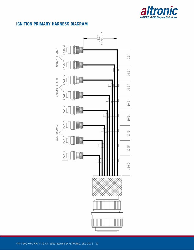
3.5 Ignition Primary Harness – On-engine wiring harness that connects the ignition junction box to the ignition coils. This harness is constructed from PLTC-ER-rated cable, making it suitable for use in hazardous areas—provided the applicable electrical codes are followed. Each engine bank requires one harness; select the harness with the appropriate number of outputs for your application.
3.6 Magnetic Pickups – The CPU-95 ignition uses two magnetic pickups to determine position information used in calculating ignition timing. See forms CPU-95 AL and CPU-95 II for additional documentation.
3.7 Cycle Trigger – The CPU-95 ignition uses a cycle trigger system to determine position information used in calculating ignition timing. See forms CPU-95 AL and CPU-95 II for additional documentation.
3.8 Flange Ignition Coil – The flange-style ignition coil is used in conjunction with the mating Caterpillar flange-coil valve cover to deliver high-voltage ignition pulses to the sparkplugs. The standard-duration 591018 coil is specified for new installations, but the long-duration 591012 coil can be used when required.
3.9 DET-1600 Detonation Detection System – See form DET-1600 IOM for complete explanation.
3.10 #1 Cylinder and “G” Lead Cable – Used to obtain #1 cylinder primary and ignition “G” lead from the ignition junction box as required by the DET-1600. Additional components may be required to route these signals to the DET-1600.
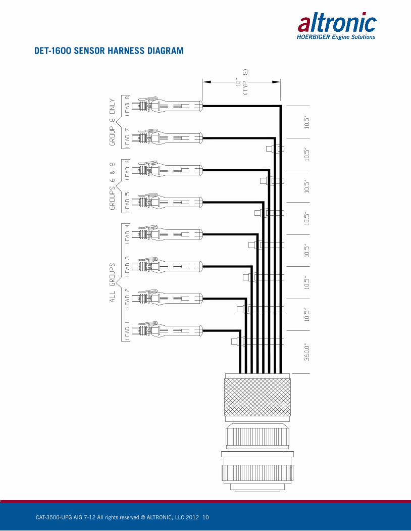
3.11 DET-1600 Sensor Harness – On-engine wiring harness that connects the enclosure containing the DET-1600 to the engine detonation sensors. This harness terminates in a standard MS-5015-style 19-pin connector. An appropriate, panel-mount mate to this connector can be included in an enclosure built by Altronic Controls or sourced separately. Each engine bank requires one harness; select the harness with the appropriate number of inputs for your application.
3.12 DSG-1682DUPS Gauge – See form DSG-1682DUPS II for complete explanation.
3.13 Additional OEM Components for EIS – Given the mechanical design of the EIS ignition system, additional OEM components are required to allow the engine to accept standard ignition coils and secondary systems. Altronic does not provide these components. The simplified list below should be used as reference only. Always consult the appropriate engine documentation to determine the exact configuration and quantity required.
CATERPILLAR SYSTEM COMPONENTS (not provided by Altronic)
DESCRIPTION 3508 SI 3512 SI 3516 SI 3508 EIS 3512 EIS 35616 EIS
Valve Cover, 3RC X X X 6 10 14
Valve Cover with Vent, 3RC X X X 2 2 2
Valve Cover Seal X X X 8 12 16
Oil Protection Tube X X X 8 12 16
O-Ring, Oil Protection Tube (#1) X X X 8 12 16
O-Ring, Oil Protection Tube (#2) X X X 8 12 16
Retainer, Oil Protection Tube X X X 8 12 16
Bolt, Oil Protection Tube X X X 8 12 16
Washer, Oil Protection Tube X X X 8 12 16
Spark Plug Extension X X X 8 12 16

CAT-3500-UPG AIG 7-12 All rights reserved © ALTRONIC, LLC 2012 6
4.0 Application Example4.1 Ignition Timing vs. Engine Speed – For this example, it is assumed that the
appropriate Ignition Timing vs. Engine Speed function has been defined as show in Figure 1.1. From this it can be determined that the most advanced ignition timing value desired is 28° before top dead center (BTDC) – thus 28° BTDC equals 0° of ignition retard (RET). Continuing this process of extrapolating the desired ignition timing vs. engine speed breakpoints it is possible to express the desired ignition timing in terms of °RET. This process generates the graph shown in Figure 1.2. Once the function is expressed in terms of °RET it is possible to program this behavior into the CPU-95 using the “RPM Map” function of the terminal program – see Figure 1.3.
CAUTION: This section of the manual is intended to explain the method of configuring the various ignition timing controls in the Caterpillar G3500 retrofit system. The values used in the following application example ARE IN NO WAY REPRESENTATIVE OF ACTUAL VALUES USED IN A FUNCTIONING SYSTEM, and are only intended to help the reader understand how the system components interact. Always refer to appropriate engine documentation and ensure that only qualified personnel establish appropriate ignition timing values.
FIG. 1.3
CAT-3500-UPG AIG 7-12 All rights reserved © ALTRONIC, LLC 2012 7
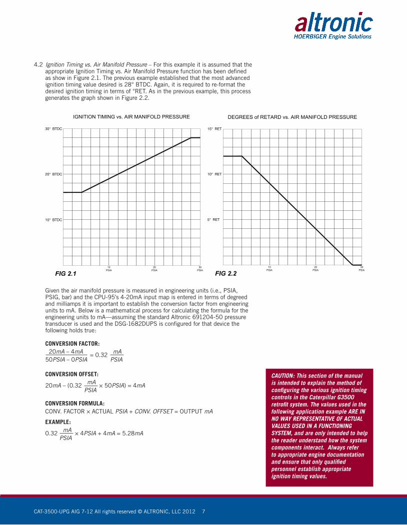
4.2 Ignition Timing vs. Air Manifold Pressure – For this example it is assumed that the appropriate Ignition Timing vs. Air Manifold Pressure function has been defined as show in Figure 2.1. The previous example established that the most advanced ignition timing value desired is 28° BTDC. Again, it is required to re-format the desired ignition timing in terms of °RET. As in the previous example, this process generates the graph shown in Figure 2.2.
Given the air manifold pressure is measured in engineering units (i.e., PSIA, PSIG, bar) and the CPU-95’s 4-20mA input map is entered in terms of degreed and milliamps it is important to establish the conversion factor from engineering units to mA. Below is a mathematical process for calculating the formula for the engineering units to mA—assuming the standard Altronic 691204-50 pressure transducer is used and the DSG-1682DUPS is configured for that device the following holds true:
CONVERSION FACTOR: 20mA – 4mA = 0.32 mA 50PSIA – 0PSIA PSIA
CONVERSION OFFSET: 20mA – (0.32 mA × 50PSIA) = 4mA PSIA
CONVERSION FORMULA: CONV. FACTOR × ACTUAL PSIA + CONV. OFFSET = OUTPUT mA
EXAMPLE: 0.32 mA × 4PSIA + 4mA = 5.28mA PSIA
CAUTION: This section of the manual is intended to explain the method of configuring the various ignition timing controls in the Caterpillar G3500 retrofit system. The values used in the following application example ARE IN NO WAY REPRESENTATIVE OF ACTUAL VALUES USED IN A FUNCTIONING SYSTEM, and are only intended to help the reader understand how the system components interact. Always refer to appropriate engine documentation and ensure that only qualified personnel establish appropriate ignition timing values.
CAT-3500-UPG AIG 7-12 All rights reserved © ALTRONIC, LLC 2012 8
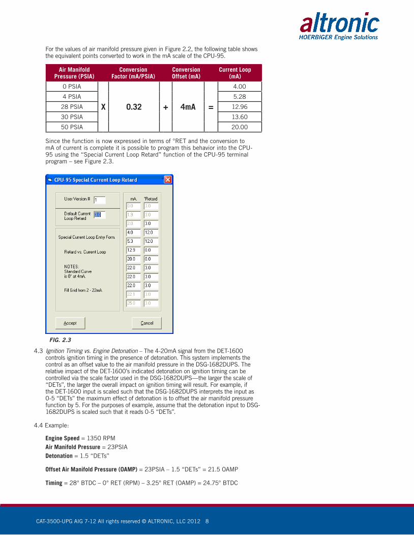
For the values of air manifold pressure given in Figure 2.2, the following table shows the equivalent points converted to work in the mA scale of the CPU-95.
Air ManifoldPressure (PSIA)
ConversionFactor (mA/PSIA)
ConversionOffset (mA)
Current Loop(mA)
0 PSIA
X 0.32 + 4mA =
4.00
4 PSIA 5.28
28 PSIA 12.96
30 PSIA 13.60
50 PSIA 20.00
Since the function is now expressed in terms of °RET and the conversion to mA of current is complete it is possible to program this behavior into the CPU-95 using the “Special Current Loop Retard” function of the CPU-95 terminal program – see Figure 2.3.
FIG. 2.3
4.3 Ignition Timing vs. Engine Detonation – The 4-20mA signal from the DET-1600 controls ignition timing in the presence of detonation. This system implements the control as an offset value to the air manifold pressure in the DSG-1682DUPS. The relative impact of the DET-1600’s indicated detonation on ignition timing can be controlled via the scale factor used in the DSG-1682DUPS—the larger the scale of “DETs”, the larger the overall impact on ignition timing will result. For example, if the DET-1600 input is scaled such that the DSG-1682DUPS interprets the input as 0-5 “DETs” the maximum effect of detonation is to offset the air manifold pressure function by 5. For the purposes of example, assume that the detonation input to DSG-1682DUPS is scaled such that it reads 0-5 “DETs”.
4.4 Example:
Engine Speed = 1350 RPM Air Manifold Pressure = 23PSIA Detonation = 1.5 “DETs”
Offset Air Manifold Pressure (0AMP) = 23PSIA – 1.5 “DETs” = 21.5 OAMP
Timing = 28° BTDC – 0° RET (RPM) – 3.25° RET (OAMP) = 24.75° BTDC
CAT-3500-UPG AIG 7-12 All rights reserved © ALTRONIC, LLC 2012 9
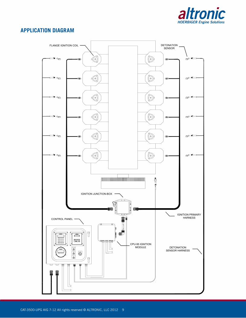
IGN. FIRING
POWERALARM
FAULT
IGNITION JUNCTION-BOX
FLANGE IGNITION COIL
DETONATIONSENSOR HARNESS
IGNITION PRIMARYHARNESS
DETONATIONSENSOR
CONTROL PANEL
CPU-95 IGNITIONMODULE
APPLICATION DIAGRAM
CAT-3500-UPG AIG 7-12 All rights reserved © ALTRONIC, LLC 2012 10
DET-1600 SENSOR HARNESS DIAGRAM
CAT-3500-UPG AIG 7-12 All rights reserved © ALTRONIC, LLC 2012 11
IGNITION PRIMARY HARNESS DIAGRAM