applicability of recycled hdpe for rotational moldingarvifinalreport.fi/files/d4.1-13_applicability...
TRANSCRIPT
Förnamn Efternamn
Applicability of recycled HDPE for Rotational Molding
Maria Dvorak
Degree Thesis
Degree Programme: Plastics Technology
2016
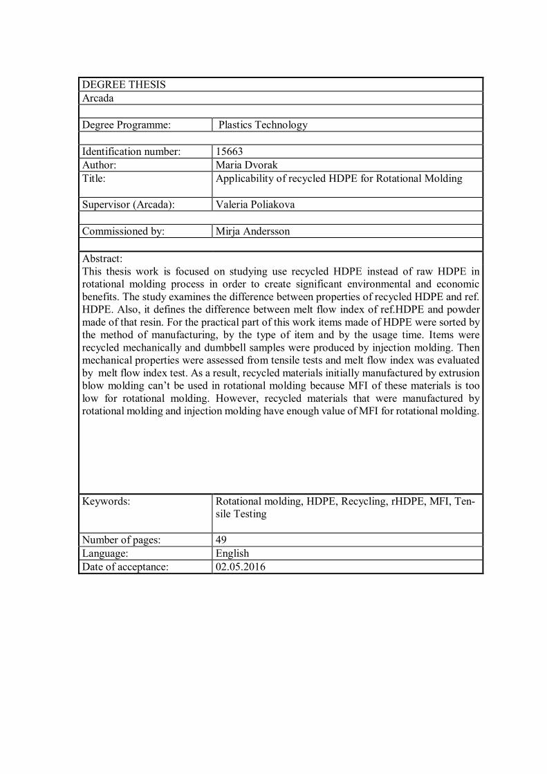
DEGREE THESIS Arcada Degree Programme: Plastics Technology Identification number: 15663 Author: Maria Dvorak Title: Applicability of recycled HDPE for Rotational Molding
Supervisor (Arcada): Valeria Poliakova Commissioned by: Mirja Andersson Abstract: This thesis work is focused on studying use recycled HDPE instead of raw HDPE in rotational molding process in order to create significant environmental and economic benefits. The study examines the difference between properties of recycled HDPE and ref. HDPE. Also, it defines the difference between melt flow index of ref.HDPE and powder made of that resin. For the practical part of this work items made of HDPE were sorted by the method of manufacturing, by the type of item and by the usage time. Items were recycled mechanically and dumbbell samples were produced by injection molding. Then mechanical properties were assessed from tensile tests and melt flow index was evaluated by melt flow index test. As a result, recycled materials initially manufactured by extrusion blow molding can’t be used in rotational molding because MFI of these materials is too low for rotational molding. However, recycled materials that were manufactured by rotational molding and injection molding have enough value of MFI for rotational molding. Keywords: Rotational molding, HDPE, Recycling, rHDPE, MFI, Ten-
sile Testing
Number of pages: 49 Language: English Date of acceptance: 02.05.2016
CONTENTS
1 Introduction .......................................................................................................... 8
1.1 Background ............................................................................................................... 8 1.2 Aims .......................................................................................................................... 9
2 Literature review .................................................................................................. 9
2.1 Rotational Molding ..................................................................................................... 9 2.1.1 Overview of Rotational Molding .......................................................................... 9 2.1.2 Rotational Molding Process .............................................................................. 10
2.2 Materials for Rotational Molding ............................................................................... 12 2.2.1 High Density Polyethylene ................................................................................ 13 2.2.2 Grinding ........................................................................................................... 14 2.2.3 Requirements of the materials .......................................................................... 16
2.3 Mechanical recycling................................................................................................ 22
3 Methods .............................................................................................................. 24
3.1 Materials and equipment for further recycling and testing ......................................... 24 3.1.1 Materials .......................................................................................................... 24 3.1.2 Equipment........................................................................................................ 27
3.2 Preparation of samples for testing ............................................................................ 28 3.2.1 Recycling process ............................................................................................ 28 3.2.2 Injection Molding .............................................................................................. 33
3.3 Testing .................................................................................................................... 37 3.3.1 Melt Flow Index ................................................................................................ 37 3.3.2 Tensile Testing ................................................................................................. 38
4 Results ............................................................................................................... 39
4.1 Melt Flow Index ....................................................................................................... 39 4.2 Tensile Testing ........................................................................................................ 40
5 Discussion ......................................................................................................... 41
5.1 MFI .......................................................................................................................... 41 5.2 Tensile Testing ........................................................................................................ 42
6 Conclusion ......................................................................................................... 42
7 Suggestions for further work ............................................................................ 43
References ................................................................................................................ 45
Appendices ............................................................................................................... 46
Figures
Figure 1. Principles of rotational molding of plastics (Subramanian, 2011) ................. 12
Figure 2. Stages in the grinding of powders (Crawford and Kearns, 2003) .................. 15
Figure 3. Good particle shapes for rotational molding powders (Crawford and Throne,
2002) .......................................................................................................................... 17
Figure 4. Typical particle size distributions for polyethylene (Crawford and Kearns, 2003)
................................................................................................................................... 18
Figure 5. Variation of dry flow rate with bulk density for rotomolding powders (Crawford
and Throne, 2002) ....................................................................................................... 19
Figure 6. HDPE identification code ............................................................................. 28
Figure 7. Thin rim left by the split mold ...................................................................... 29
Figure 8. Washing process .......................................................................................... 30
Figure 9. Drying process ............................................................................................. 30
Figure 10. Rapid shredder ........................................................................................... 31
Figure 11. Flakes of bottles ......................................................................................... 31
Figure 12. Continuous polymer product (strand) ......................................................... 32
Figure 13. Pellets of recycled watering pots ................................................................ 32
Figure 14. Extrusion of recycled pallet ........................................................................ 33
Figure 15. Engel Injection Molding machine ............................................................... 34
Figure 16. Mitaten Extrusion plastometer .................................................................... 37
Figure 17. Tensile testing of rHDPE panel .................................................................. 38
Tables
Table 1. Common engineering properties of HDPE (Vasile and Pascu, 2005) ............. 14
Table 2. Property changes of PE with increasing melt index (Crawford and Kearns, 2012)
................................................................................................................................... 21
Table 3. Classification of used materials in the experiment ......................................... 25
Table 4. Data about materials that were used ............................................................... 26
Table 5. Optimization of parameters for Injection Molding ......................................... 35

Table 6. A process of recycling and preparation of samples in pictures ....................... 36
Table 7. Results of MFI Test ....................................................................................... 39
Table 8. Results of Tensile Testing ............................................................................. 40

Abbreviations
HDPE High Density Polyethylene
MFI Melt Flow Index
PE Polyethylene
rHDPE Recycled High Density Polyethylene

7
FOREWORD
I would like to express my sincere gratitude to my supervisor Valeria Poliakova for her
support, expert guidance and inspiration throughout my research.
I wish to thank my examiner Mirja Andersson for counselling when I decided to start my
thesis.
I am also grateful to Erland Nyroth for technical help and his advices during my work in
the laboratory.
I would like to acknowledge the valuable input to this research of company Motoral Oy
Motoplast, which gave me HDPE powder, granules and rotomolded item for further test-
ing.
Helsinki, April 2016
Maria Dvorak
8
1 INTRODUCTION
1.1 Background
Rotational molding is a thermoplastic process for producing hollow parts by placing pow-
der or liquid resin into a hollow mold and then rotating it bi-axially in an oven until the
resin melts and coats the inside of the mold cavity. Next the tool is cooled and the part is
removed from the mold.
Rotational molding industry is developing rapidly since the 1950s especially compared
with other types of plastics processing industry. Although, various factors inhibit the de-
velopment, such as slower processing cycle and limitations of the materials used.
Nowadays approximately 90% of the materials used in rotational molding is polyethylene
(Linear Low Density Polyethylene, Medium Density Polyethylene and High Density Pol-
yethylene). HDPE is used widely in rotational molding because it has excellent chemical
resistance, very high stiffness, good processability and low cost. HDPE is non-biode-
gradable and can take centuries to decompose, so it is imperative that products made of
HDPE are recycled and used again. Moreover, HDPE can be easily recycled.
Recycling is important for many reasons and it is a part of global efforts to reduce plastic
in the waste stream. It helps to reduce the high rates of plastic pollution and to conserve
natural resources, specifically oil, which is a nonrenewable natural resource available
only in limited supply. Also, the process of recycling plastic requires less energy and
fossil fuels, it results in fewer greenhouse gas emissions including carbon dioxide, which
contributes significantly to the global warming effect. Recycling plastic helps to conserve
limited landfill space that can be used for other waste.
Moreover, it is forbidden to landfill packaging items since 1.1.2016 according to Finnish
law for waste (Jätelaki 646/2011). Packaging plastic items are available, and recycling
can be done easily.
9
It is clear from these observations that using recycled HDPE instead of raw HDPE can
create significant environmental and economic benefits. Therefore, this work focuses on
finding a way to use rHDPE instead of raw HDPE in rotational molding.
1.2 Aims
The main aim of this work is to find out applicability of recycled HDPE for rotational
molding. It will be discussed after approaching three main objectives of this work:
Define a requirements of the materials for rotational molding.
Compare MFI and mechanical properties of recycled HDPE with properties of ref.
HDPE.
Find the most suitable rHDPE for further production of powder.
2 LITERATURE REVIEW
2.1 Rotational Molding
2.1.1 Overview of Rotational Molding
Rotational molding, also known as rotomoulding or rotocasting, is a low pressure, high
temperature manufacturing method for producing hollow, one-piece plastic parts. The
basic principle of forming a coating on the inside surface of a rotating mold dates back
for many centuries, but the process did not gain recognition as a molding method for
plastics until the 1940s. In the 1950s the use of the rotational molding process expanded
more quickly due to the introduction of powdered grades of polyethylene specifically
developed for the process.
There are many advantages associated with the rotational molding process. Firstly the
molds are simple and relatively cheap. This is because rotational molding is a low-pres-
sure process and therefore it is not necessary to manufacture the molds from expensive
metal alloys, as in the injection molding process. The wall thickness of parts produced by
10
rotational molding is more uniform in comparison to products from other processes and
it is possible to alter the wall thickness of the part without altering the mold. Complex
parts with undercuts and intricate contours can be manufactured relatively easily by rota-
tional molding. It is also possible to produce double wall moldings. During rotational
molding relatively little waste is produced since the required weight of the part is placed
inside the mold.
One of the main disadvantages associated with rotational molding is that the number of
materials suitable for the process is more limited than for other plastics manufacturing
processes. Also, the cycle times are much longer than those of other processes because
both the plastic and mold must be heated from room temperature to the molding temper-
ature for the plastic and then subsequently cooled to room temperature during each cycle.
Common applications for rotomoulded products include:
Material handling products- tanks, chemical drums, shipping containers, wheeled
bins, hoppers and coal bunkers.
Industrial products- pump housings, pipe fittings, effluent ducts, air ducts, sewer
linings, safety helmets, paramedic stretchers and light fittings.
Automotive products -truck mudguards, ducting, diesel fuel tanks, toolboxes and
tractor dashboards.
Environmental products- litter bins, sanitation bins and bottle banks.
Leisure products- canoes, kayaks, windsurfing boards, boats, trailers, toys, play-
ground furniture and mannequins.
Marine products- floats, buoys, life belts and floating decks.
Road signage- road barriers, road cones and road signs. (Crawford and Kearns,
2012)
2.1.2 Rotational Molding Process
The plastic powder is placed in one half of the mold portion. The mold is then closed and
subjected to biaxial rotation in an oven with required processing temperature. The plastic
powder inside the mold is melted by heat transferred through the mold wall. After all of
11
the powder has melted, the mold is moved out of the oven, while biaxial rotation contin-
ues. Still air, a blowing fan, or a water shower is usually used to cool the mold. Once the
product inside the mold is cooled to a state of sufficient rigidity, the mold opens and the
product is removed.
During the tumbling process, the finer powder particles get sieved down closer to the wall
and larger particles form layers on top. As the temperature rises in the mold, the powder
softens and melts, adhering to the mold wall and forming a homogenous, bubble free melt
pool along the entire inside surface of the mold. Biaxial rotation ensures that the powder
is evenly distributed in the mold. After the heating cycle is completed, the mold is cooled
resulting in solidification of the polymer. The amount of powder determines the wall
thickness of the rotomolded part.
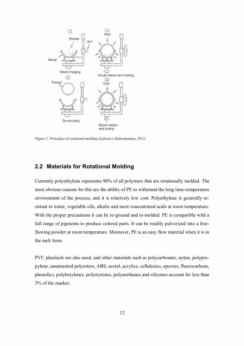
Rotational molding process involves four steps. They are:
1. In the separable cast or fabricated vented mold, pre-determined and weighed
amount of powdered plastic material is charged;
2. The powdered material is heated in an oven with biaxial rotation and external
heating without applying pressure or centrifugal force until powdered plastic
melts and coats in the internal surface of the mold;
3. After all of the powder has melted, the mold is moved out of the oven, while
biaxial rotation continues. Rotating mold is cooled externally with forced air or
water mist to allow the molding to solidify;
4. Removing the part from the mold's cavity. (Subramanian, 2011)
Figure 1 illustrates the principle of rotational molding of plastics.
12
Figure 1. Principles of rotational molding of plastics (Subramanian, 2011)
2.2 Materials for Rotational Molding
Currently polyethylene represents 90% of all polymers that are rotationally molded. The
most obvious reasons for this are the ability of PE to withstand the long time-temperature
environment of the process, and it is relatively low cost. Polyethylene is generally re-
sistant to water, vegetable oils, alkalis and most concentrated acids at room temperature.
With the proper precautions it can be re-ground and re-molded. PE is compatible with a
full range of pigments to produce colored parts. It can be readily pulverized into a free-
flowing powder at room temperature. Moreover, PE is an easy flow material when it is in
the melt form.
PVC plastisols are also used, and other materials such as polycarbonate, nylon, polypro-
pylene, unsaturated polyesters, ABS, acetal, acrylics, cellulosics, epoxies, fluorocarbons,
phenolics, polybutylenes, polystyrenes, polyurethanes and silicones account for less than
3% of the market.
13
The powder form of polymers is used in rotational molding process. Some materials, such
as plastisols, can be used as liquids, others, such as nylons, can be used as granules due
to their high flowability once molten. (Crawford and Kearns, 2003)
2.2.1 High Density Polyethylene
Polyethylene (PE) was discovered in 1933 by Reginald Gibson and Eric Fawcett at the
British industrial giant, Imperial Chemical Industries. This widely used plastic is a poly-
mer of ethylene, CH2 =CH2, having the formula (–CH2 CH 2–) n. It is produced at high
pressures and temperatures in the presence of any one of several catalysts, depending on
the desired properties of the end-use product.
HDPE is more rigid and harder than lower density materials with a molecular weight
below 300,000 g/mol. The extremely high molecular weight of HDPE combined with its
very low coefficient of friction produces an excellent abrasion-resistant product which is
resistant to gouging, scuffing, and scraping.
It is also more prone to warpage due to its higher crystallinity, which makes it very sen-
sitive to differential cooling rates across the walls of rotomoulded products. HDPE also
has higher shrinkage than LDPE. HDPE is also non-toxic and non-staining.
Moreover, HDPE is a low cost material with an excellent balance between stiffness and
toughness, over a wide temperature range. In its natural state it is a translucent, milky
white material. This can be a drawback in applications where absolute transparency is
important. It is easily pigmented and thus is available in a wide range of colors.
HDPE can be processed very easily by injection molding, extrusion, blow molding, rota-
tional molding, and so on.
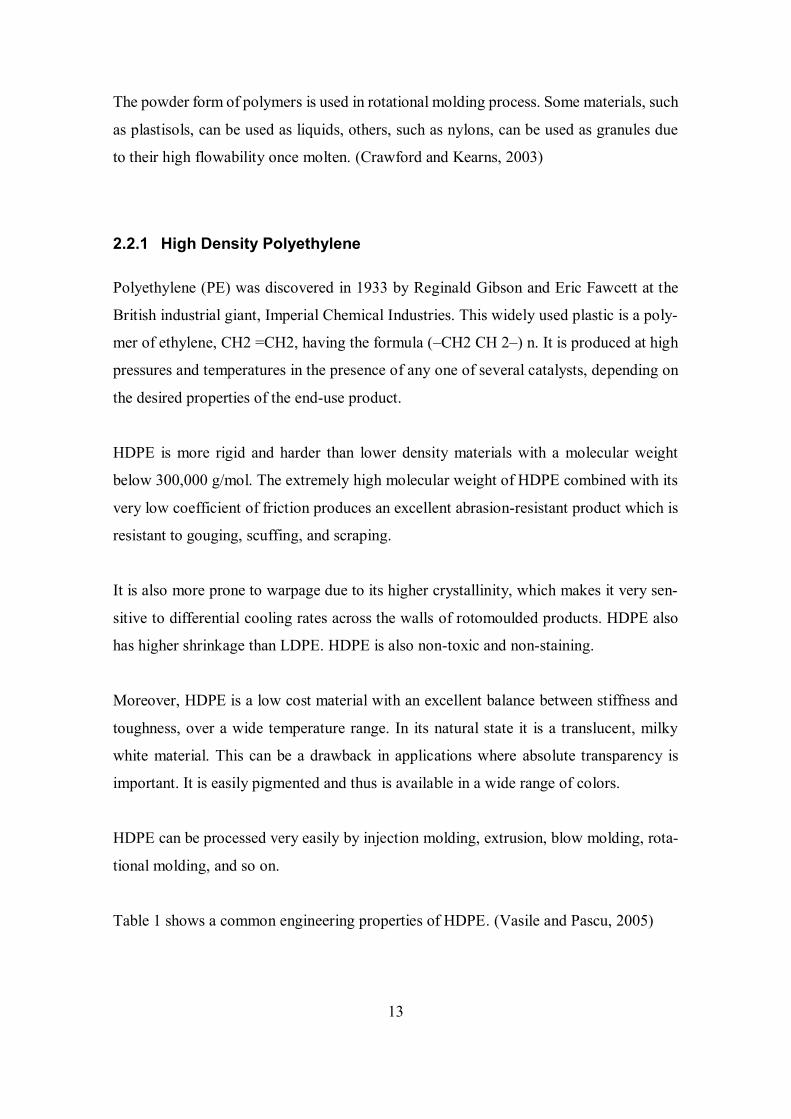
Table 1 shows a common engineering properties of HDPE. (Vasile and Pascu, 2005)
14
Table 1. Common engineering properties of HDPE (Vasile and Pascu, 2005)
Property Value
Density (g/cm³) 0.941-0.965
Tensile Strength (MPa) 20-35
Tensile Modulus (MPa) 413-1241
Flexural modulus (GPa) 0.75-1.575
Strain at Yield (%) 15
Melting temperature
(˚C)
120-130
Max. operating
temperature (°C)
82
Specific heat (kJ/kg/ K
at 25 °C)
2.22– 2.3
Thermal conductivity
(W/m/°C)
4.63– 5.22 × 10 –3
Cristallinity (%) 60-90
2.2.2 Grinding
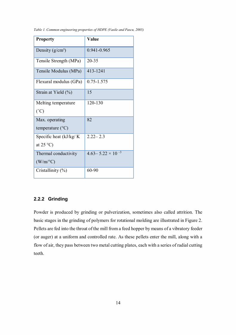
Powder is produced by grinding or pulverization, sometimes also called attrition. The
basic stages in the grinding of polymers for rotational molding are illustrated in Figure 2.
Pellets are fed into the throat of the mill from a feed hopper by means of a vibratory feeder
(or auger) at a uniform and controlled rate. As these pellets enter the mill, along with a
flow of air, they pass between two metal cutting plates, each with a series of radial cutting
teeth.
15
Figure 2. Stages in the grinding of powders (Crawford and Kearns, 2003)
Each pellet is slowly reduced in size as particles are shaved off it and it moves outwards
into the narrowing gap between the two cutting faces. The particles remain between the
plates until they are of a size that allows them to escape from the gap at the periphery.
In the grinding process, frictional heat increases the temperature of the metal cutting
faces, as well as the individual polyethylene particles and the surrounding air. As a con-
sequence, the temperature must be controlled so that it does not rise beyond the melting
point of the polyethylene or to a critical softening temperature, prior to melting, when the
particles begin to adhere to each other. This can cause blockages in the passage of new
material entering the mill.
Once the particles exit the mill they go into an air stream, which carries them to a screen-
ing unit containing a number of sieves of a standard mesh size. Particles that pass through
the screens are taken out of the system and collected as usable powder. Those particles
that do not pass through are conveyed back to the mill and reground.
There are factors affecting powder quality: gap between the discs, feed rate of granules,
system pressure, disc design, disc speed, choice and type of feeder, cooling efficiency,
16
operating temperature, moisture control, air velocity, amount of recycle, type of auxiliary
equipment used, amperage of the mill and sieve aperture in the screen unit. (Crawford
and Kearns, 2003)
2.2.3 Requirements of the materials
Due to the importance of grindability, particle size distribution, particle shape, pourabil-
ity, bulk density, thermal stability, MFI and shear viscosity to successful rotational mold-
ing, these aspects are considered in detail in the following sections.
Grindability
The grindability of a material means that the resin can be ground to a fine powder. Resin
grades that have very low melting points may not be easy to grind in the high-speed im-
pact mills that have proven to give the most consistently good powder because they melt.
In some cases a low melting resin can be ground under an atmosphere of liquid nitrogen
or some other cooling method so that the material will not become too hot during melting
operation. (Strong, 2005)
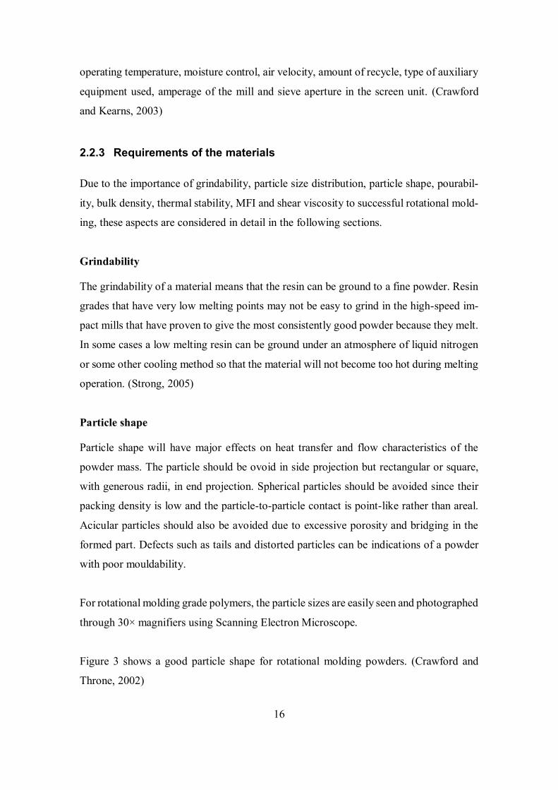
Particle shape
Particle shape will have major effects on heat transfer and flow characteristics of the
powder mass. The particle should be ovoid in side projection but rectangular or square,
with generous radii, in end projection. Spherical particles should be avoided since their
packing density is low and the particle-to-particle contact is point-like rather than areal.
Acicular particles should also be avoided due to excessive porosity and bridging in the
formed part. Defects such as tails and distorted particles can be indications of a powder
with poor mouldability.
For rotational molding grade polymers, the particle sizes are easily seen and photographed
through 30× magnifiers using Scanning Electron Microscope.
Figure 3 shows a good particle shape for rotational molding powders. (Crawford and
Throne, 2002)
17
Figure 3. Good particle shapes for rotational molding powders (Crawford and Throne, 2002)
Particle size distribution
High-speed attrition mills grind pellets approximately 5-6 mm in diameter down to the
required particle size-distribution. The mesh size is a measure of the size of the screen
mesh through which 95% of the particles will pass. The meshes are defined by standards
adopted by each country. (Strong, 2005)
While particles are still characterized widely by mesh size, the current trend is to charac-
terize them by the size of the opening in millimeters. Normally powder particles for rota-
tional molding vary from less than 150 microns to about 500 microns (35 mesh) which
correspond to hole openings of 0,15 mm to 0,5 mm. It affords a compromise between
grinding rates and the fusion characteristics of the polymer. For successful rotational
molding particle size distribution should be 95% < 500 micron with maximum 15% <
150 micron. (Nugent, 1990)
The particle size distribution of rotational molding powders is measured according to
ASTM test method D-1921. A set of nested, stacked, welded wire sieves, with mesh sizes
ranging from about 35 mesh to 200 mesh is used for this determination, which correspond
to hole openings of 0,5 mm to 0,074 mm. Basically a thief of powder is taken, weighed,
and placed in the top sieve of the sieve stack. The shaker is covered and mounted in a
device that rotates, shakes, and vibrates. After a predetermined period of time, the sieves
are separated and the amount of powder retained on each sieve is weighed.
18
Although vibratory sieves of the type described above are the most commonly used in the
rotational molding industry, there are other ways of measuring particle size distribution:
elutriation, streaming, sedimentation and fluidization. (Crawford and Throne, 2002)
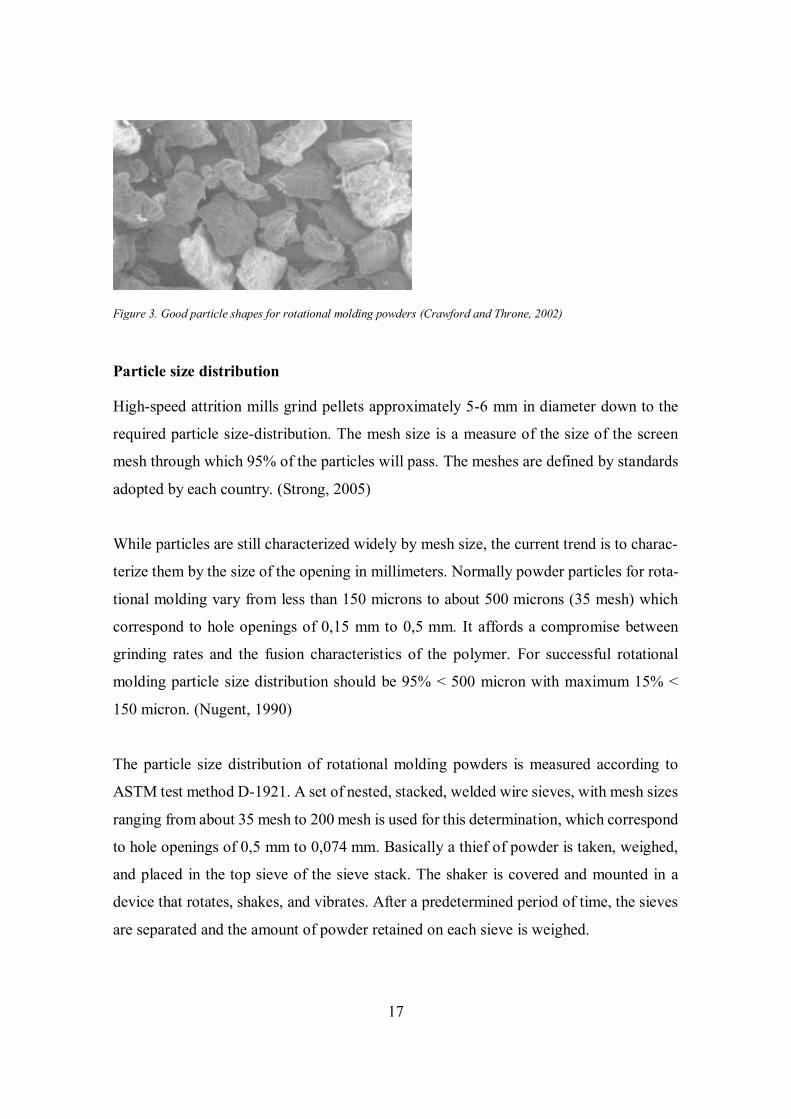
Figure 4 shows a typical particle size distribution for polyethylene used successfully by
rotomolders. This particle size distribution skewed towards the larger particles below 500
microns produce moldings of good quality. (Crawford and Kearns, 2003)
Figure 4. Typical particle size distributions for polyethylene (Crawford and Kearns, 2003)
Pourability
Powder dry flow properties are important during rotational molding as they determine
how the polymer distributes itself within the mold and how well the polymer melt flows
into complex shapes. Dry flow depends mainly on particle size and particle shape. Since
the particle size distribution of a 35 mesh powder tends not to vary greatly, it is the particle
shape that has the greatest effect on dry flow. The presence of tails on powder particles
reduces dry flow properties, leading to detrimental part properties such as bridging across
narrow recesses in the mold and high void content within the part wall.
The standard method for measuring the dry flow of a powder is described in ASTM D-
1895. It is the time taken for 100 g of powder to flow through a standard funnel. The dry
flow is quoted in seconds.

19
When the funnel that is defined by ASTM Test Procedure 1895-69 is used, a minimum
flow rate of 185 g/min characterizes acceptable rotational molding powders. (Crawford
and Throne, 2002)
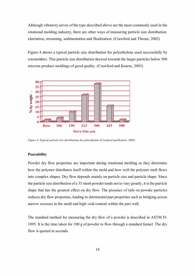
Bulk density
Bulk density is a measure of the efficiency with which the powder particles pack together.
A good quality powder having “clean” particles with no tails will have a high bulk den-
sity. Bulk density and dry flow are dependent on the particle shape, particle size, and
particle size distribution of the powder. These two properties are inversely related, in that
an increase in the bulk density corresponds to a faster dry flow rate, as shown in Figure
5. Bulk density should be more than 320 kg/m3 for successful rotational molding. (Craw-
ford and Throne, 2002)
Bulk density (kg/m3) = Dry weight (kg) / volume (m3)
Figure 5. Variation of dry flow rate with bulk density for rotomolding powders (Crawford and Throne, 2002)
Thermal stability
Good heat stabilization is needed to survive prolonged exposure to heat in an oxidative
atmosphere. (Strong, 2005)
20
Melt Flow Index
MFI test is a method of determining and comparing the flow of melts under standard
conditions. A vertical load is applied to a piston and the polymer melt is squeezed through
a die. The amount of polymer that is extruded in a fixed time gives a measure of the flow
as a MFI. An ‘easy flow’ grade of plastic will have a high MFI, which corresponds to a
low viscosity.
Different MFI values are preferred for different plastics manufacturing methods. The low
MFI material is useful in manufacturing method where the strength of the resin in the
melt phase is important, such as in blow molding. High MFI indicates a low molecular
weight resin which is useful in achieving high throughputs in manufacturing method, such
as injection molding. (Subramanian, 2013)
In rotational molding void-free parts are usually achieved with HDPE melt indexes in the
range of 3 to 8 g/10 min (Crawford and Throne, 2002). Resins with high melt index num-
bers are chosen when the part is very complex and good flow into complicated areas is
required (Strong, 2005). However, a higher MFI is associated with lower impact strength,
stress crack resistance, chemical resistance and weatherability. These effects of increasing
of MFI on properties of PE are summarized in Table 2 (Crawford and Kearns, 2003).
Resins with low melt index numbers are chosen when improved stress crack resistance,
impact toughness, or creep resistance is needed. From a physical performance viewpoint,
the low-melt index resins would always be preferred, but they are difficult to mold and
cannot be used for some parts. (Strong, 2005)
21
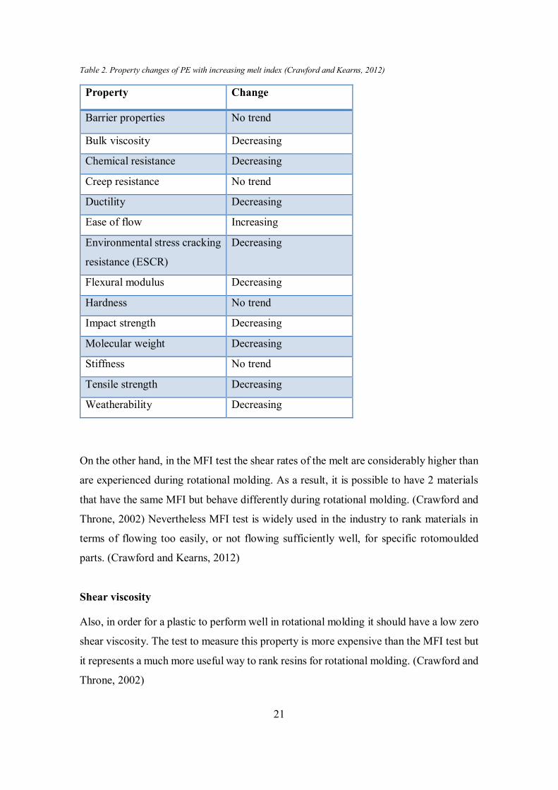
Table 2. Property changes of PE with increasing melt index (Crawford and Kearns, 2012)
On the other hand, in the MFI test the shear rates of the melt are considerably higher than
are experienced during rotational molding. As a result, it is possible to have 2 materials
that have the same MFI but behave differently during rotational molding. (Crawford and
Throne, 2002) Nevertheless MFI test is widely used in the industry to rank materials in
terms of flowing too easily, or not flowing sufficiently well, for specific rotomoulded
parts. (Crawford and Kearns, 2012)
Shear viscosity
Also, in order for a plastic to perform well in rotational molding it should have a low zero
shear viscosity. The test to measure this property is more expensive than the MFI test but
it represents a much more useful way to rank resins for rotational molding. (Crawford and
Throne, 2002)
Property Change
Barrier properties No trend
Bulk viscosity Decreasing
Chemical resistance Decreasing
Creep resistance No trend
Ductility Decreasing
Ease of flow Increasing
Environmental stress cracking
resistance (ESCR)
Decreasing
Flexural modulus Decreasing
Hardness No trend
Impact strength Decreasing
Molecular weight Decreasing
Stiffness No trend
Tensile strength Decreasing
Weatherability Decreasing

22
2.3 Mechanical recycling
Mechanical recycling is the process of converting discarded plastic into new products,
principally by melting and molding. The waste plastic used may come from the manufac-
turing process or from post-consumer products. This is the simplest way of recycling
plastic waste, demanding the lowest initial investments.
In this form of recycling, the macromolecular nature of the polymer is not destroyed, so
that the degradation reactions that directly affect the physical and chemical properties of
the polymer are minimized and controlled. Nevertheless, chemical changes that occurred
during the original processing and in-service use may have a negative effect on the quality
of products reprocessed by mechanical recycling, in comparison with those manufactured
from virgin resin.
Mechanical recycling involves several steps: collection, separation and sorting, shred-
ding, cleaning of the plastic to eliminate organic matter, drying (particularly important
for polymers that are hydrolyzed) and reprocessing. These aspects are considered in detail
in the following sections.
Collection
Waste collection is the starting point for any recycling process. This stage is often done
to gather all kind of plastics into the single place for further processing. There are two
main sources in which plastic wastes can pollute the environment: post-consumer plastics
and post-industrial plastics. Post-consumer plastics can be easily collected for further re-
cycling in residential areas where people put plastic in waste bins, and also it can be col-
lected from the roadside. Post-industrial plastics can be collected from the industry, for
example, it can be plastics waste and defected products.
Separation and sorting
Separation of the different types of plastic and sorting of plastic material from mixed
waste are very important stages in mechanical recycling because quite different plastics
cannot be used for the same end. If plastic is separated and sorted improperly, it could
affect the quality of the produced resin.

23
Separation and sorting consist of three steps: the identification is made directly by resin
identification codes, then the identified product is correlated with the most likely material,
and certain properties specific to each material are determined.
Shredding
The stage of breaking into flakes or binding together is mainly done to reduce the overall
volume taken up by the plastic residues. Also, it is done to promote the interaction of
those residues with the cleaning solution. It normally occurs between separation and
cleaning of the plastics.
However, the size of the flakes produced at this stage may interfere with the cleaning
efficiency. Also, during extrusion of the plastic, depending on the system used, the size
of flakes in the feed can be a hindrance to the feeding process.
Cleaning
Plastics during their use and disposal come into contact with other compounds, and their
composition may be changed by contaminants permeating through and impregnating the
material. Therefore, cleaning should be done in order to remove contaminants from the
material like dust, oil, labels, etc.
The cleaning, in most cases, takes between 5 and 20 minutes at temperatures up to 88 °C.
Short times do not suffice to remove adhesives, while the use of baths at high tempera-
tures facilitates the removal of glue. Plastics can be washed with surfactants (detergents)
or sodium hydroxide (Na0H) solution.
Drying
The drying stage should be done in order to reduce the water content in plastics. The
conditions chosen for drying depend on the type of humidity and the way it is bound to
the material, on the size and shape of the particles, and on the degree of crystallinity.
Usually, it is done using a drying machine at recommended drying temperature of the
material.
24
Reprocessing
After the water content has been reduced, the material proceeds to the reprocessing step,
which directly affects the eventual quality of the end-product. At this point, the polymer
mixture is formulated in accordance with the target application. Stabilizers, reinforce-
ments, other types of polymer, coupling agents, flame retardants, foaming agents may be
added to the polymer.
Extrusion and pelletizing are done in order to obtain a pellets. The flakes are fed into an
extruder where they are heated to melting state and forced through the die converting into
a continuous polymer product (strand). Then the strands are cooled by water and cut into
pellets, which may be used for new polymer products manufacturing. Extrusion is done
according to the material data sheet of the specific material. For example, for PE the tem-
perature zones of the extruder have range between 190 - 200°C. (Manrich and S.F. Santos,
2009)
3 METHODS
3.1 Materials and equipment for further recycling and testing
3.1.1 Materials
In the experiment were used items made of HDPE that were sorted into different catego-
ries: by the method of manufacturing, by the type of item and by the usage time.
Items that were manufactured by injection molding, extrusion blow molding and rota-
tional molding were chosen because materials manufactured by different manufacturing
methods have different MFI values. Also, packaging and non-packaging items were cho-
sen according to the information of Finnish laws about waste (Jätelaki 646/2011,
Valtioneuvoston asetus pakkauksista ja pakkausjätteistä 518/2014).
25
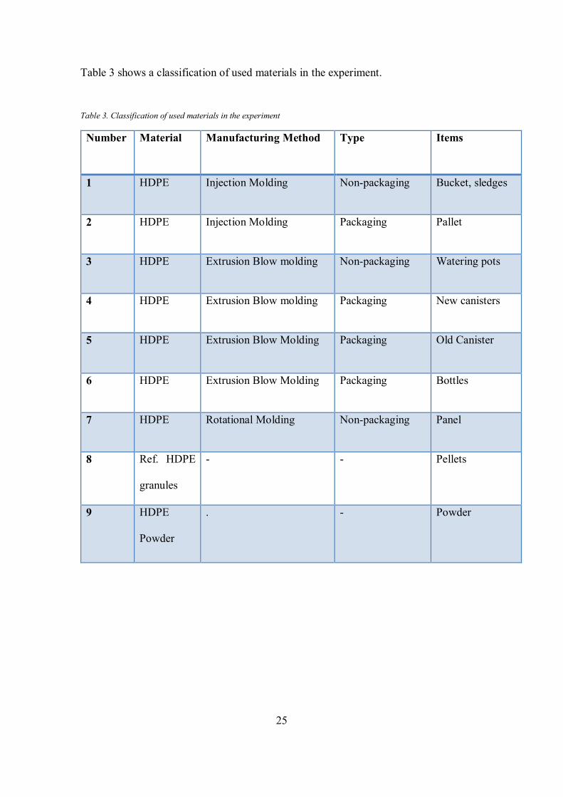
Table 3 shows a classification of used materials in the experiment.
Table 3. Classification of used materials in the experiment
Number Material Manufacturing Method Type Items
1 HDPE Injection Molding Non-packaging Bucket, sledges
2 HDPE Injection Molding Packaging Pallet
3 HDPE Extrusion Blow molding Non-packaging Watering pots
4 HDPE Extrusion Blow molding Packaging New canisters
5 HDPE Extrusion Blow Molding Packaging Old Canister
6 HDPE Extrusion Blow Molding Packaging Bottles
7 HDPE Rotational Molding Non-packaging Panel
8 Ref. HDPE
granules
- - Pellets
9 HDPE
Powder
. - Powder
26
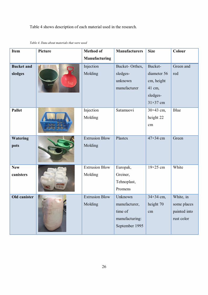
Table 4 shows description of each material used in the research.
Table 4. Data about materials that were used
Item Picture Method of
Manufacturing
Manufacturers Size Colour
Bucket and
sledges
Injection
Molding
Bucket- Orthex,
sledges-
unknown
manufacturer
Bucket-
diameter 56
cm, height
41 cm,
sledges-
31×37 cm
Green and
red
Pallet
Injection
Molding
Satamuovi 30×43 cm,
height 22
cm
Blue
Watering
pots
Extrusion Blow
Molding
Plastex 47×34 cm Green
New
canisters
Extrusion Blow
Molding
Europak,
Greiner,
Tehnoplast,
Promens
19×25 cm
White
Old canister
Extrusion Blow
Molding
Unknown
manufacturer,
time of
manufacturing:
September 1995
34×34 cm,
height 70
cm
White, in
some places
painted into
rust color
27
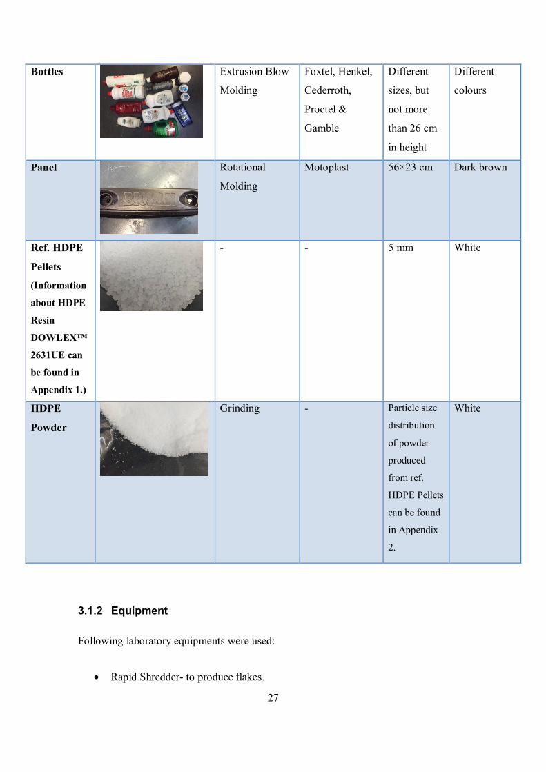
Bottles
Extrusion Blow
Molding
Foxtel, Henkel,
Cederroth,
Proctel &
Gamble
Different
sizes, but
not more
than 26 cm
in height
Different
colours
Panel
Rotational
Molding
Motoplast
56×23 cm
Dark brown
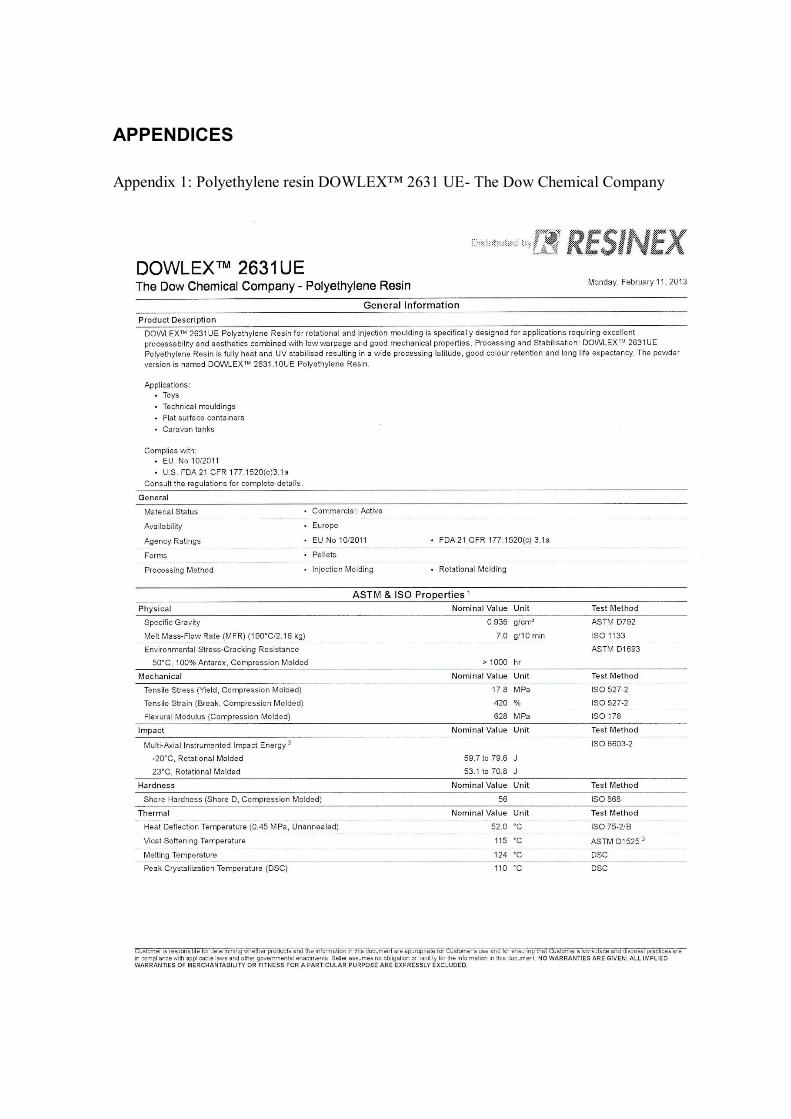
Ref. HDPE
Pellets
(Information
about HDPE
Resin
DOWLEX™
2631UE can
be found in
Appendix 1.)
- - 5 mm White
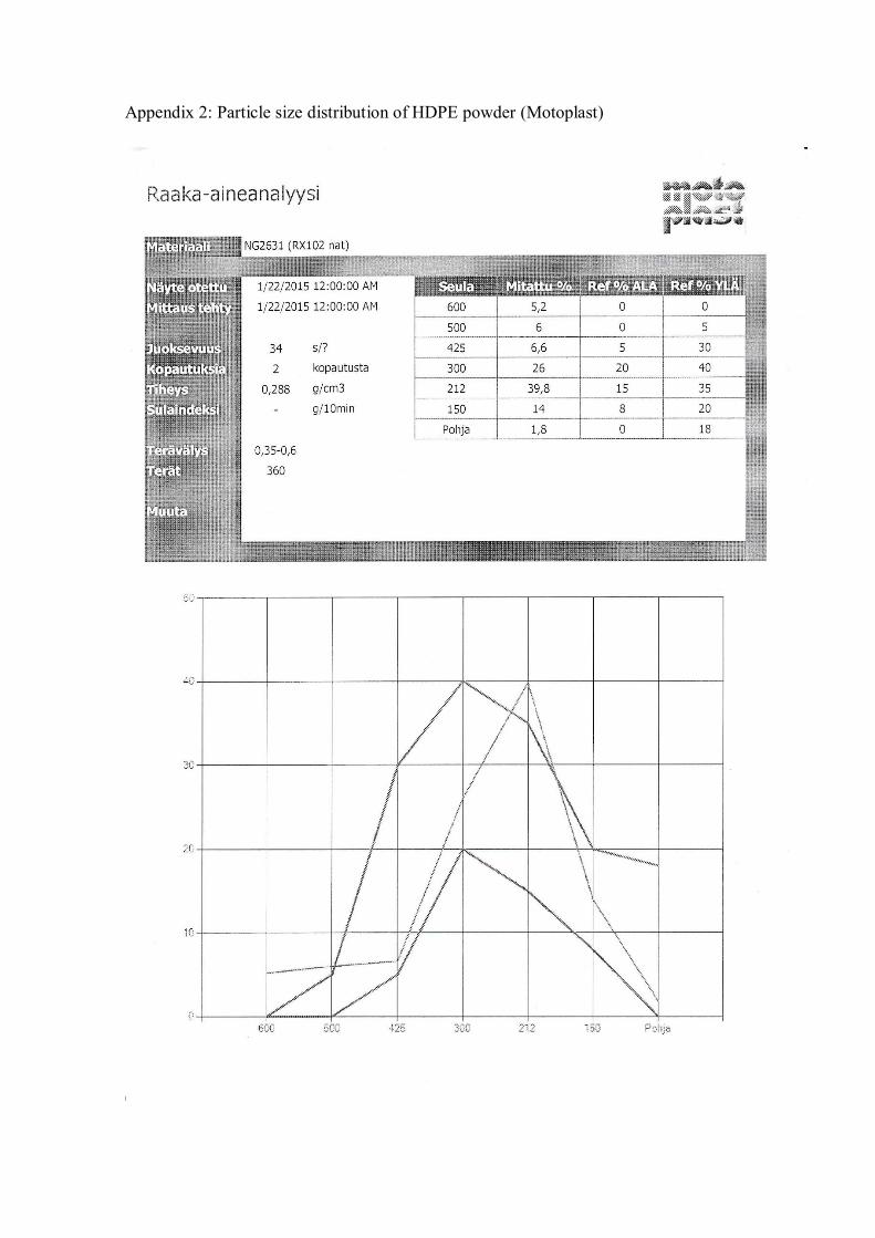
HDPE
Powder
Grinding - Particle size
distribution
of powder
produced
from ref.
HDPE Pellets
can be found
in Appendix
2.
White
3.1.2 Equipment
Following laboratory equipments were used:
Rapid Shredder- to produce flakes.
28
Nova BS 400 Heavy duty band saw- to cut pieces of plastic.
Labotek Flexible Modular Drying Unit FMD-MM-25-40-v- to dry flakes.
KFM Eco Ex Extruder with a screw L/D ratio of 25/D and a screw diameter of 18
mm- to produce pellets.
ENGEL ES 200/50HL CC90 Injection molding machine- to produce dumbbell
samples.
Testometric M 350- 5CT Material testing machine with wedge grips- to test me-
chanical properties.
Mitaten MEP 2/PC Extrusion plastometer- to test MFI.
3.2 Preparation of samples for testing
Pelletizing from post-consumer materials included collection, sorting, washing, drying,
cutting, shredding, extrusion and pelletizing. Then dumbbell samples were produced us-
ing ENGEL Injection molding machine.
3.2.1 Recycling process
Collection
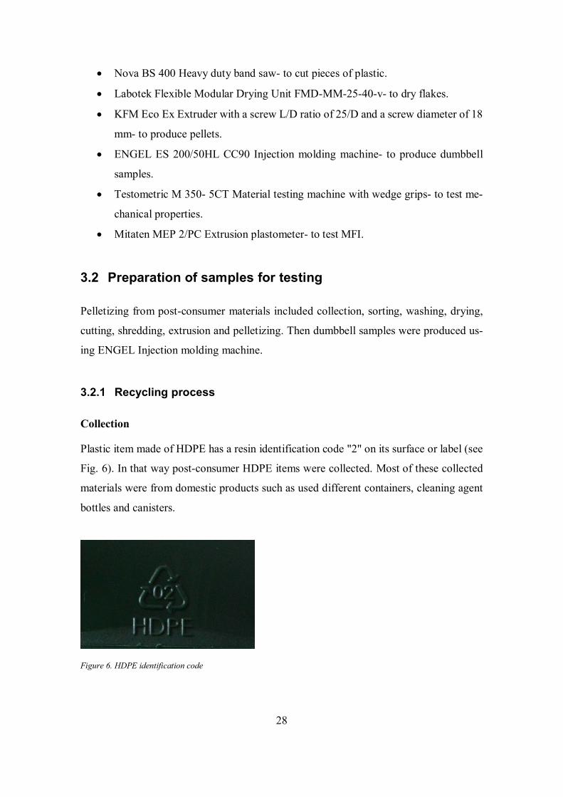
Plastic item made of HDPE has a resin identification code "2" on its surface or label (see
Fig. 6). In that way post-consumer HDPE items were collected. Most of these collected
materials were from domestic products such as used different containers, cleaning agent
bottles and canisters.
Figure 6. HDPE identification code
29
Sorting
The collected plastics were sorted and separated into different categories: by the method
of manufacturing, by the type of item and by the usage time.
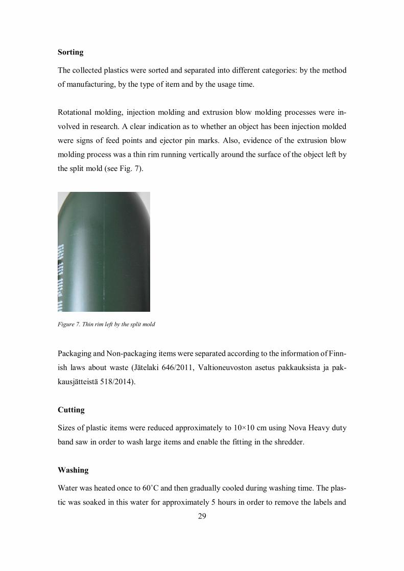
Rotational molding, injection molding and extrusion blow molding processes were in-
volved in research. A clear indication as to whether an object has been injection molded
were signs of feed points and ejector pin marks. Also, evidence of the extrusion blow
molding process was a thin rim running vertically around the surface of the object left by
the split mold (see Fig. 7).
Figure 7. Thin rim left by the split mold
Packaging and Non-packaging items were separated according to the information of Finn-
ish laws about waste (Jätelaki 646/2011, Valtioneuvoston asetus pakkauksista ja pak-
kausjätteistä 518/2014).
Cutting
Sizes of plastic items were reduced approximately to 10×10 cm using Nova Heavy duty
band saw in order to wash large items and enable the fitting in the shredder.
Washing
Water was heated once to 60˚C and then gradually cooled during washing time. The plas-
tic was soaked in this water for approximately 5 hours in order to remove the labels and
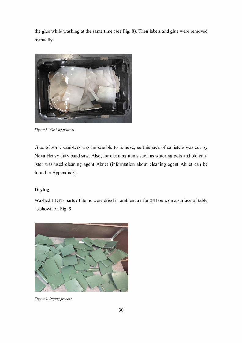
30
the glue while washing at the same time (see Fig. 8). Then labels and glue were removed
manually.
Figure 8. Washing process
Glue of some canisters was impossible to remove, so this area of canisters was cut by
Nova Heavy duty band saw. Also, for cleaning items such as watering pots and old can-
ister was used cleaning agent Abnet (information about cleaning agent Abnet can be
found in Appendix 3).
Drying
Washed HDPE parts of items were dried in ambient air for 24 hours on a surface of table
as shown on Fig. 9.
Figure 9. Drying process
31
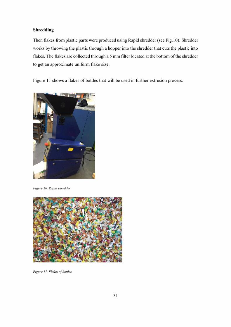
Shredding
Then flakes from plastic parts were produced using Rapid shredder (see Fig.10). Shredder
works by throwing the plastic through a hopper into the shredder that cuts the plastic into
flakes. The flakes are collected through a 5 mm filter located at the bottom of the shredder
to get an approximate uniform flake size.
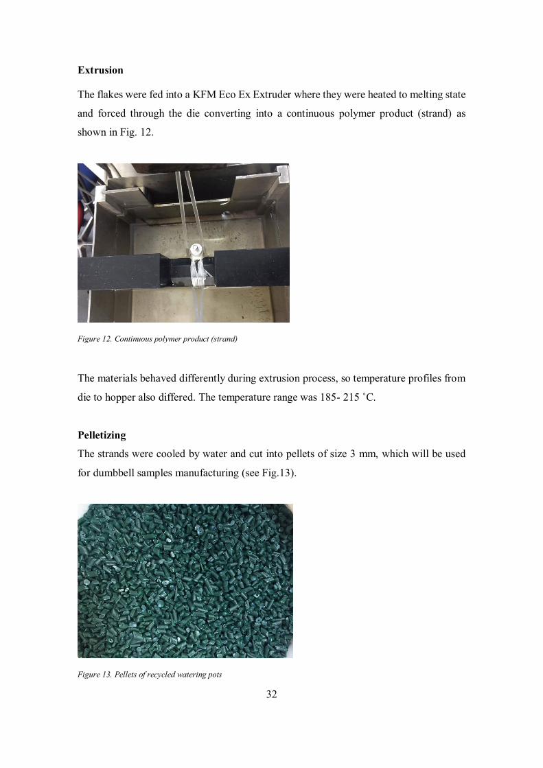
Figure 11 shows a flakes of bottles that will be used in further extrusion process.
Figure 10. Rapid shredder
Figure 11. Flakes of bottles
32
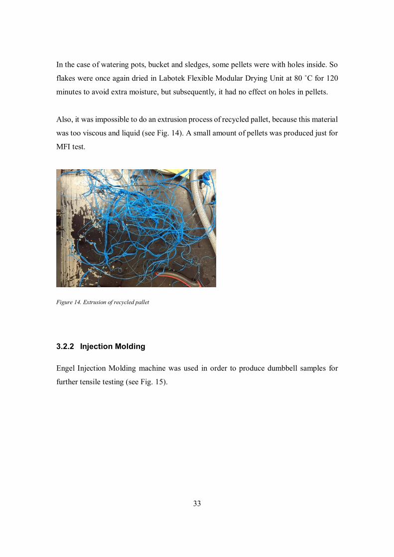
Extrusion
The flakes were fed into a KFM Eco Ex Extruder where they were heated to melting state
and forced through the die converting into a continuous polymer product (strand) as
shown in Fig. 12.
Figure 12. Continuous polymer product (strand)
The materials behaved differently during extrusion process, so temperature profiles from
die to hopper also differed. The temperature range was 185- 215 ˚C.
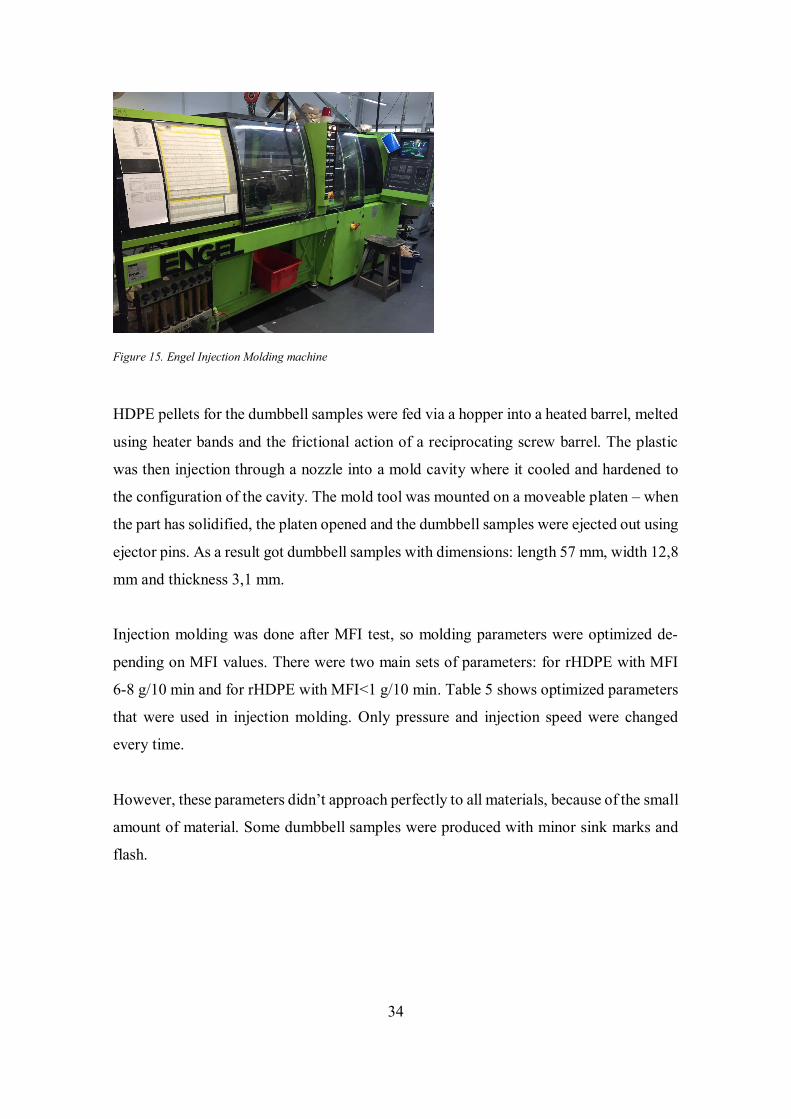
Pelletizing
The strands were cooled by water and cut into pellets of size 3 mm, which will be used
for dumbbell samples manufacturing (see Fig.13).
Figure 13. Pellets of recycled watering pots
33
In the case of watering pots, bucket and sledges, some pellets were with holes inside. So
flakes were once again dried in Labotek Flexible Modular Drying Unit at 80 ˚C for 120
minutes to avoid extra moisture, but subsequently, it had no effect on holes in pellets.
Also, it was impossible to do an extrusion process of recycled pallet, because this material
was too viscous and liquid (see Fig. 14). A small amount of pellets was produced just for
MFI test.
Figure 14. Extrusion of recycled pallet
3.2.2 Injection Molding
Engel Injection Molding machine was used in order to produce dumbbell samples for
further tensile testing (see Fig. 15).
34
Figure 15. Engel Injection Molding machine
HDPE pellets for the dumbbell samples were fed via a hopper into a heated barrel, melted
using heater bands and the frictional action of a reciprocating screw barrel. The plastic
was then injection through a nozzle into a mold cavity where it cooled and hardened to
the configuration of the cavity. The mold tool was mounted on a moveable platen – when
the part has solidified, the platen opened and the dumbbell samples were ejected out using
ejector pins. As a result got dumbbell samples with dimensions: length 57 mm, width 12,8
mm and thickness 3,1 mm.
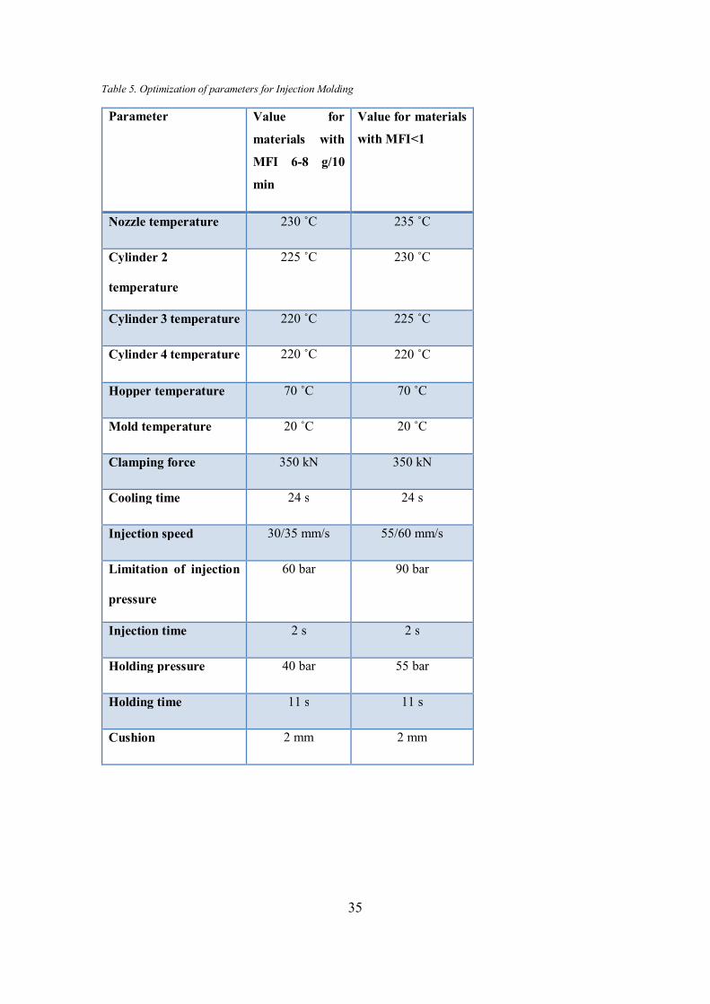
Injection molding was done after MFI test, so molding parameters were optimized de-
pending on MFI values. There were two main sets of parameters: for rHDPE with MFI
6-8 g/10 min and for rHDPE with MFI˂1 g/10 min. Table 5 shows optimized parameters
that were used in injection molding. Only pressure and injection speed were changed
every time.
However, these parameters didn’t approach perfectly to all materials, because of the small
amount of material. Some dumbbell samples were produced with minor sink marks and
flash.
35
Table 5. Optimization of parameters for Injection Molding
Parameter Value for
materials with
MFI 6-8 g/10
min
Value for materials
with MFI˂1
Nozzle temperature 230 ˚C 235 ˚C
Cylinder 2
temperature
225 ˚C 230 ˚C
Cylinder 3 temperature 220 ˚C 225 ˚C
Cylinder 4 temperature 220 ˚C 220 ˚C
Hopper temperature 70 ˚C 70 ˚C
Mold temperature 20 ˚C 20 ˚C
Clamping force 350 kN 350 kN
Cooling time 24 s 24 s
Injection speed 30/35 mm/s 55/60 mm/s
Limitation of injection
pressure
60 bar 90 bar
Injection time 2 s 2 s
Holding pressure 40 bar 55 bar
Holding time 11 s 11 s
Cushion 2 mm 2 mm
36
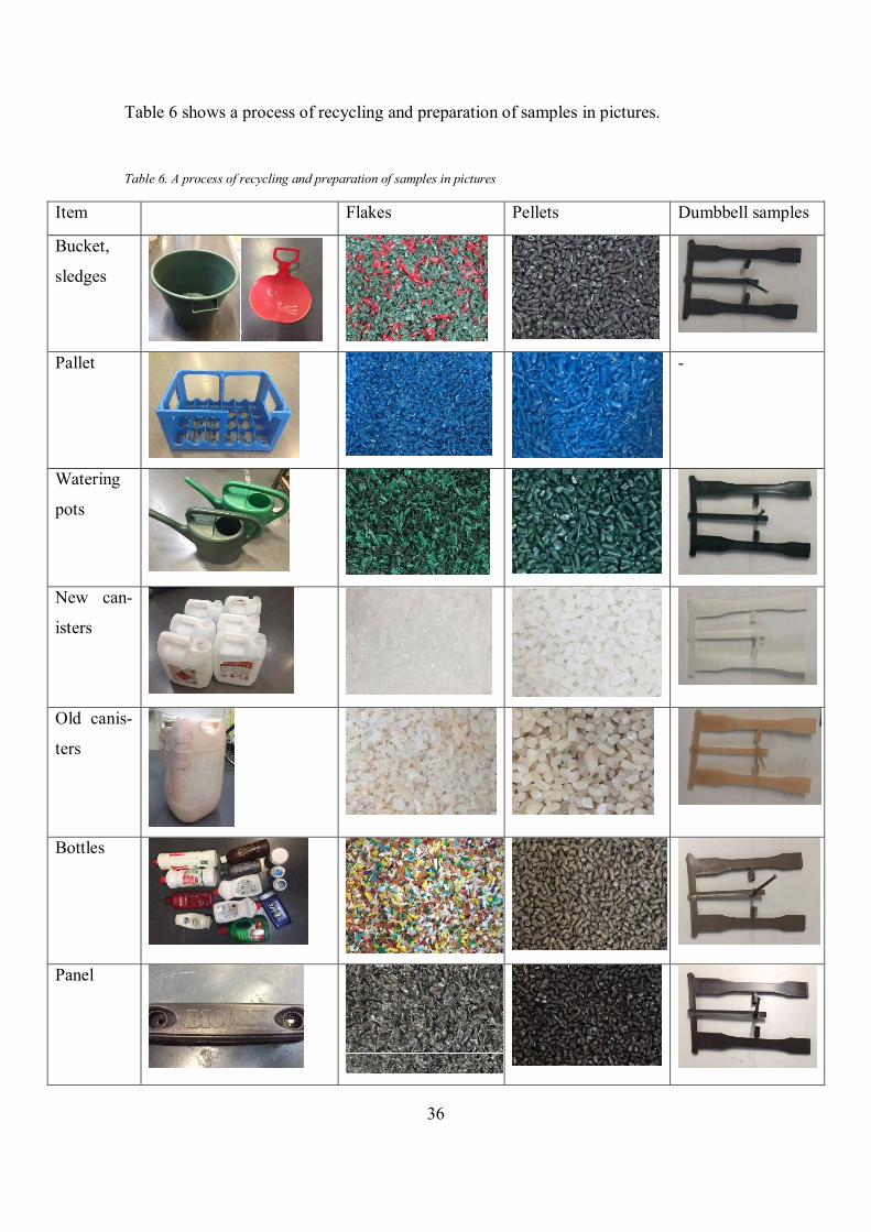
Table 6 shows a process of recycling and preparation of samples in pictures.
Table 6. A process of recycling and preparation of samples in pictures
Item Flakes Pellets Dumbbell samples
Bucket,
sledges
Pallet
-
Watering
pots
New can-
isters
Old canis-
ters
Bottles
Panel
37
Ref.
HDPE
- -
3.3 Testing
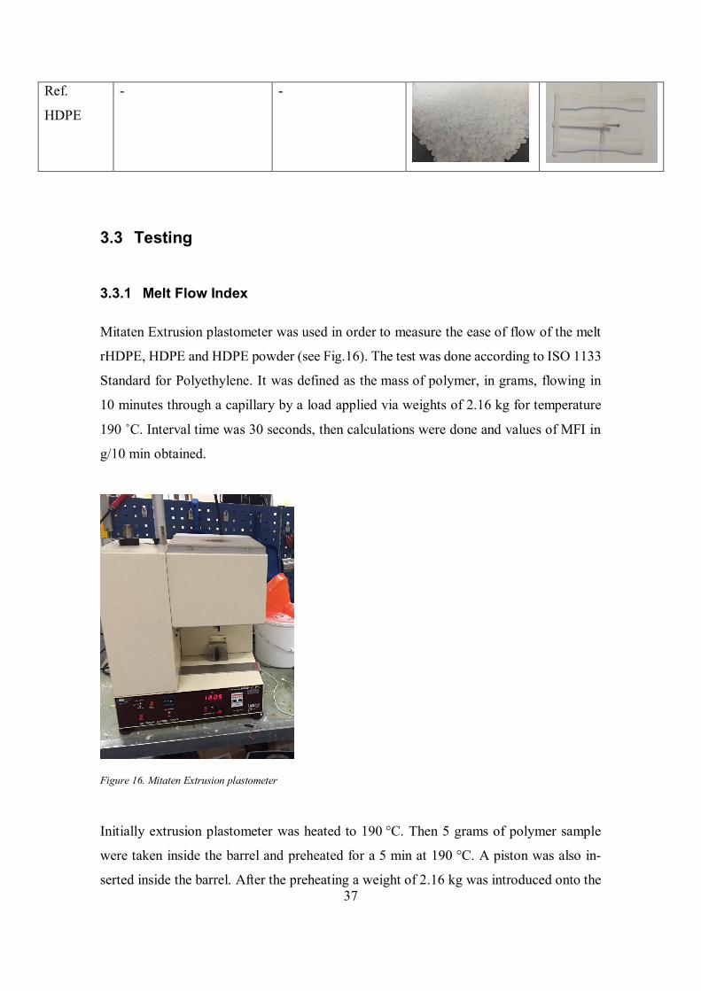
3.3.1 Melt Flow Index
Mitaten Extrusion plastometer was used in order to measure the ease of flow of the melt
rHDPE, HDPE and HDPE powder (see Fig.16). The test was done according to ISO 1133
Standard for Polyethylene. It was defined as the mass of polymer, in grams, flowing in
10 minutes through a capillary by a load applied via weights of 2.16 kg for temperature
190 ˚C. Interval time was 30 seconds, then calculations were done and values of MFI in
g/10 min obtained.
Figure 16. Mitaten Extrusion plastometer
Initially extrusion plastometer was heated to 190 °C. Then 5 grams of polymer sample
were taken inside the barrel and preheated for a 5 min at 190 °C. A piston was also in-
serted inside the barrel. After the preheating a weight of 2.16 kg was introduced onto the
38
piston according to ISO1133 Standard. Molten polymer immediately started to flow
through the die. Then 5 samples of the melt were taken after 30 seconds and were weighed
accurately. Average MFI was expressed in grams of polymer per 10 minutes of duration
of the test. Standard deviation was also calculated using values such as average of MFI
and MFI of each sample.
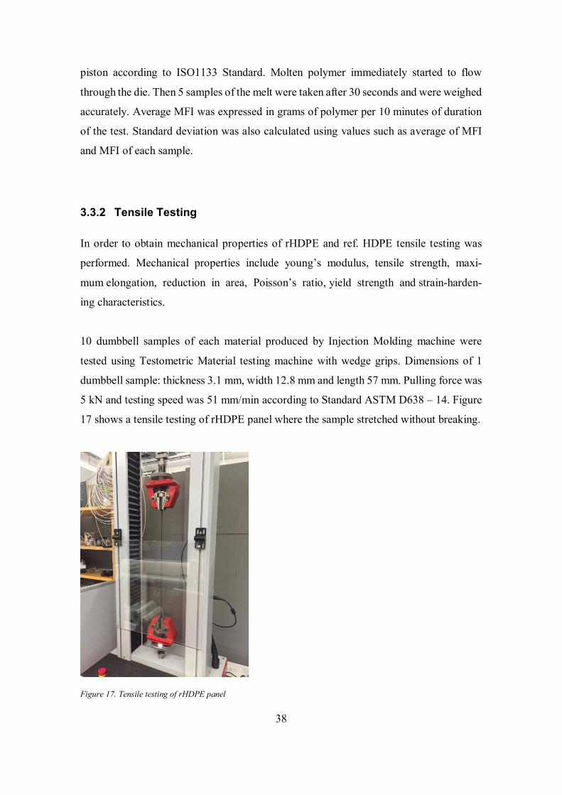
3.3.2 Tensile Testing
In order to obtain mechanical properties of rHDPE and ref. HDPE tensile testing was
performed. Mechanical properties include young’s modulus, tensile strength, maxi-
mum elongation, reduction in area, Poisson’s ratio, yield strength and strain-harden-
ing characteristics.
10 dumbbell samples of each material produced by Injection Molding machine were
tested using Testometric Material testing machine with wedge grips. Dimensions of 1
dumbbell sample: thickness 3.1 mm, width 12.8 mm and length 57 mm. Pulling force was
5 kN and testing speed was 51 mm/min according to Standard ASTM D638 – 14. Figure
17 shows a tensile testing of rHDPE panel where the sample stretched without breaking.
Figure 17. Tensile testing of rHDPE panel
39
4 RESULTS
4.1 Melt Flow Index
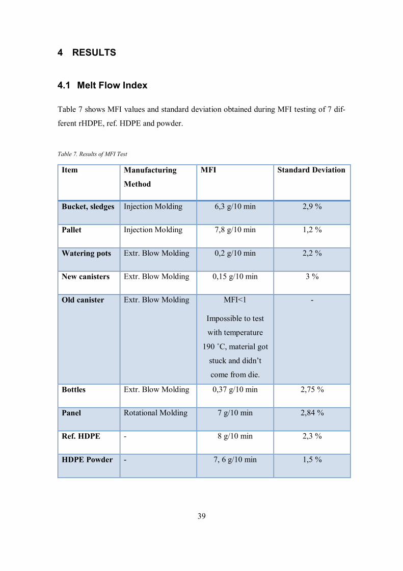
Table 7 shows MFI values and standard deviation obtained during MFI testing of 7 dif-
ferent rHDPE, ref. HDPE and powder.
Table 7. Results of MFI Test
Item Manufacturing
Method
MFI Standard Deviation
Bucket, sledges Injection Molding 6,3 g/10 min 2,9 %
Pallet Injection Molding 7,8 g/10 min 1,2 %
Watering pots Extr. Blow Molding 0,2 g/10 min 2,2 %
New canisters Extr. Blow Molding 0,15 g/10 min 3 %
Old canister Extr. Blow Molding MFI˂1
Impossible to test
with temperature
190 ˚C, material got
stuck and didn’t
come from die.
-
Bottles Extr. Blow Molding 0,37 g/10 min 2,75 %
Panel Rotational Molding 7 g/10 min 2,84 %
Ref. HDPE - 8 g/10 min 2,3 %
HDPE Powder - 7, 6 g/10 min 1,5 %
40
4.2 Tensile Testing
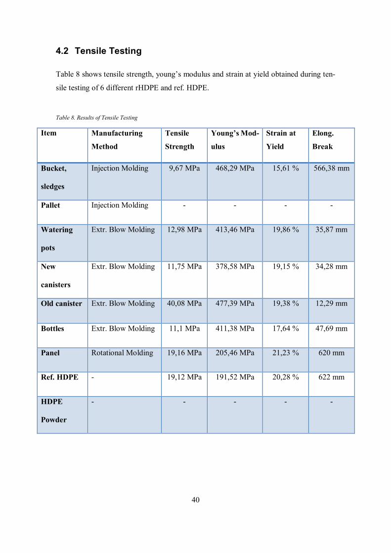
Table 8 shows tensile strength, young’s modulus and strain at yield obtained during ten-
sile testing of 6 different rHDPE and ref. HDPE.
Table 8. Results of Tensile Testing
Item Manufacturing
Method
Tensile
Strength
Young’s Mod-
ulus
Strain at
Yield
Elong.
Break
Bucket,
sledges
Injection Molding 9,67 MPa 468,29 MPa 15,61 % 566,38 mm
Pallet Injection Molding - - - -
Watering
pots
Extr. Blow Molding 12,98 MPa 413,46 MPa 19,86 % 35,87 mm
New
canisters
Extr. Blow Molding 11,75 MPa 378,58 MPa 19,15 % 34,28 mm
Old canister Extr. Blow Molding 40,08 MPa 477,39 MPa 19,38 % 12,29 mm
Bottles Extr. Blow Molding 11,1 MPa 411,38 MPa 17,64 % 47,69 mm
Panel Rotational Molding 19,16 MPa 205,46 MPa 21,23 % 620 mm
Ref. HDPE - 19,12 MPa 191,52 MPa 20,28 % 622 mm
HDPE
Powder
- - - - -
41
5 DISCUSSION
5.1 MFI
Tested MFI of ref. HDPE gives 8 g/10min and HDPE powder gives 7,6 g/10min. Their
difference of 0,4 g/10min indicates a decrease of 5%. This decrease in value of HDPE
powder can be evaluated as a result of grinding process.
However, it was noticed that there is a difference between experimentally obtained MFI
of ref. HDPE and MFI of the same resin from data sheet Polyethylene resin DOWLEX™
2631 UE (in Appendix 1). The difference is 1 g/10 min, which corresponds to 12,5 %. It
can be assumed, the factor that caused a mismatch was a low reliability of Mitaten Extru-
sion plastometer which worked not always properly during an experiment.
MFI of all recycled materials were lower than MFI of ref. HDPE. Standard deviation
didn’t exceed 3%.
Half of samples were with MFI lower than 1 g/10 min: new canisters, watering pots and
bottles. Moreover, pellets of old canister got stuck and didn’t come from the die, so it can
be concluded that old canister has also MFI˂1. All recycled materials with MFI˂1 were
manufactured initially by extrusion blow molding. It means that materials are very vis-
cous and resistant to flow. Also, a low MFI value indicates a high molecular weight pol-
ymer.
MFI of recycled materials manufactured by injection molding were 6,3 g/10 min (bucket
and sledges) and 7,8 g/10 min (pallet). Panel that was manufactured by rotational molding
had MFI 7 g/10 min and in comparison with ref. HDPE difference is 1 g/10 min, which
corresponds to 12,5 %.
42
5.2 Tensile Testing
All recycled materials initially manufactured by extrusion blow molding had elongation
at break in the range 12,29-47,69 mm and were broken quickly in comparison with other
materials. However, these materials are not similar, because bottles, watering pots, old
canister and new canisters have different values of tensile strength, young’s modulus,
strain at yield and elongation at break. Old canister has the highest tensile strength and
young’s modulus, and the lowest elongation at break in comparison to all other materials.
Watering pots, bottles and new canisters have quite similar properties with slight differ-
ences in young’s modulus.
In contrast, panel and ref. HDPE didn’t break during tensile testing. Recycled panel that
was manufactured by rotational molding is the most similar to ref. HDPE. Their differ-
ence is just 1 % of strain at yield and 14 MPa in young’s modulus, which corresponds to
4,7% of strain at yield and 6,7 % in young’s modulus.
Material made of recycled bucket and sledges had fracture, but was stretched for a long
time because the material was very viscous. It has a lower strain at yield and tensile
strength in comparison with ref. HDPE. Young’s modulus of bucket and sledges is 468,29
MPa, it is the highest value of young’s modulus in tensile testing.
However, bottles, new canisters, watering pots, bucket and sledges had unexpectedly low
values of tensile strength. Their range is 9,67-12,96 MPa. According to Table 1, for HDPE
standard values of tensile strength are in the range 20-35 MPa. Low tensile strength values
of rHDPE materials can be evaluated as a result of degradation occurred during the recy-
cling process.
6 CONCLUSION
The purpose of this work was to find out applicability of recycled HDPE in rotational
molding. Requirements of the materials for rotational molding were defined as MFI 3-8
43
g/10 min, Particle size distribution 95% < 500 micron with maximum 15% < 150 micron,
dry flow rate minimum 185 g/min and bulk density >320 kg/m3 (p. 17-21).
In order to find the most suitable material for further production of powder, different
HDPE materials were mechanically recycled. Items made of HDPE were sorted into dif-
ferent categories: by the method of manufacturing, by the type of item and by the usage
time. Then MFI and tensile testing were performed in order to obtain values of MFI,
tensile strength, young’s modulus, strain at yield and elongation at break.
As a result, tested MFI of ref. HDPE gives 8 g/10min and HDPE powder gives 7,6
g/10min. Their difference of 0,4 g/10min indicates a decrease of 5%. This decrease in
value of HDPE powder can be evaluated as a result of grinding process.
Recycled materials initially manufactured by extrusion blow molding can’t be used in
rotational molding because of the material requirements of MFI. But it is possible to use
recycled bottles and canisters in another manufacturing processes, for example in film
extrusion.
Recycled materials that were manufactured by rotational molding and injection molding
have enough value of MFI to be used in rotational molding. However, MFI is not the only
one property which is important, so further testing of other properties such as viscosity,
dry flow rate, bulk density and particle size distribution should be done in order to be sure
that materials are suitable.
7 SUGGESTIONS FOR FURTHER WORK
Further research could be done on grinding and testing of rHDPE powder for rotational
molding. Materials chosen for recycling should be manufactured by rotational molding
and injection molding.
Also, further research could be focused on studying the differences between properties of
HDPE and powder made of that resin. One measurement of MFI already showed that

44
when the powder is produced from HDPE pellets, MFI decreases for 5%. It is possible to
test other properties in order to see what is the difference.
45
REFERENCES
Crawford, R.J. and Kearns, M.P. (2003) Practical Guide to Rotational Moulding. 1st edn.
Shrewsbury, GBR: Smithers Rapra.
Crawford, R.J. and Kearns, M.P. (2012) Practical Guide to Rotational Moulding. 2nd
edn. Shrewsbury, GBR: Smithers Rapra.
Crawford, R.J. and Throne, J.L. (2002) Rotational Molding Technology. Norwich, New
York: William Andrew Publishing.
Manrich, S. and S.F. Santos, A. (2009) Plastic Recycling. New York, US: Nova Science
Publishers.
Nugent, P.J. (1990) A study of heat transfer and process control in the rotational mould-
ing of polymer powders. Belfast.
Strong, A. B. (2005) Plastics: Materials and Processing. 2nd edn. New Jersey: Pearson
Prentice hall.
Subramanian, M.N. (2011) Basics of Troubleshooting in Plastics Processing. Hoboken,
US: Wiley-Scrivener.
Subramanian, M.N. (2013) Plastics Additives and Testing. Hoboken, US: Wiley-Scrive-
ner.
Vasile, C. and Pascu, M. (2005) Practical Guide to Polyethylene. Shawbury, Shropshire,
GBR: Rapra Technology Limited
APPENDICES
Appendix 1: Polyethylene resin DOWLEX™ 2631 UE- The Dow Chemical Company
Appendix 2: Particle size distribution of HDPE powder (Motoplast)
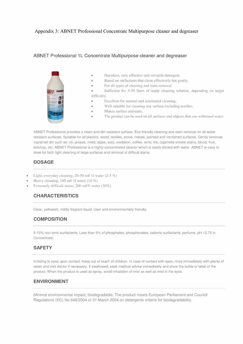
Appendix 3: ABNET Professional Concentrate Multipurpose cleaner and degreaser