appendix g-5 residential access and traffic … pipeline project residential access and traffic...
TRANSCRIPT

G5-1 Appendix G-5
APPENDIX G-5
Residential Access and Traffic Mitigation Plan

Appendix G-5 G5-2

ROVER PIPELINE LLC
Rover Pipeline Project
Residential Access and Traffic Management Plan
February 2015
G5-3 Appendix G-5
ROVER PIPELINE PROJECT Residential Access and Traffic Management Plan 1.0 INTRODUCTION The Rover Pipeline Project (Project) is a new natural gas pipeline system that will be constructed by Rover Pipeline LLC (Rover) and will consist of Supply Lateral and Mainline pipelines, compressor stations, and associated meter stations and other aboveground facilities that will be located in parts of West Virginia, Pennsylvania, Ohio, and Michigan. The Project pipelines will cross public roads that range from maintained gravel municipal roads to state highways and interstate highways. Construction of the Project will result in minor, short term impacts on the transportation system in the Project area. Potential temporary effects associated with roadway crossings include disruption of traffic flows, disturbance of existing underground utilities, such as water and sewer lines, and hindrance of emergency vehicle access. In addition, construction employees will utilize approved access roads to maneuver crews and equipment to and from the proposed right-of-way. The Residential Access and Traffic Management Plan details the process Rover will enact to minimize impacts to traffic, emergency services, and landowner access to residences while maintaining the safety of the public and Rover employees. Rover will comply with all requirements of the West Virginia, Pennsylvania, Ohio, and Michigan Departments of Transportation during construction of the Project. 2.0 CONSTRUCTION OF PIPELINES ACROSS ROADWAYS 2.1.1 Crossing Methods The decision to install the pipeline under public and private roadways, using either conventional open cut or road bore or horizontal directional drill (HDD) methods, will be based on site conditions, traffic flow, and road opening permit requirements. Generally, all paved roads will be bored. An open cut will be used where a conventional bore or HDD is not constructible and the open cut is approved, and for crossings of private roads. Table 1A-8 in Volume IIA, Resource Report 1, lists the methods by which all roads and railroads will be crossed by the Project. The pipelines will be installed at a depth of at least 5 feet below a road surface and will be designed to withstand anticipated external loadings. Construction noise during the bored or open cut road crossings will be similar to construction along any part of the pipeline. Noise at an HDD road crossing will be evaluated by Rover to ensure that no impacts will occur to noise sensitive areas near the work area. 2.2 Bore or HDD Crossing Methods Traffic on major roads will be unimpeded during installation of the pipe by use of horizontal bore or HDD construction methods. Details about general construction access and utilization of public roadways are described in Section 3.0 below. To complete a conventional bore of a roadway, two pits will be excavated, one on each side of the road to be bored. A boring machine will be lowered into one pit, and a horizontal hole is bored to a diameter approximately two inches larger than the diameter of the pipe (or casing, if required) at the depth of the pipeline installation. The pipeline section and/or casing will be pushed through the bore to the opposite
1 February 2015 Appendix G-5 G5-4

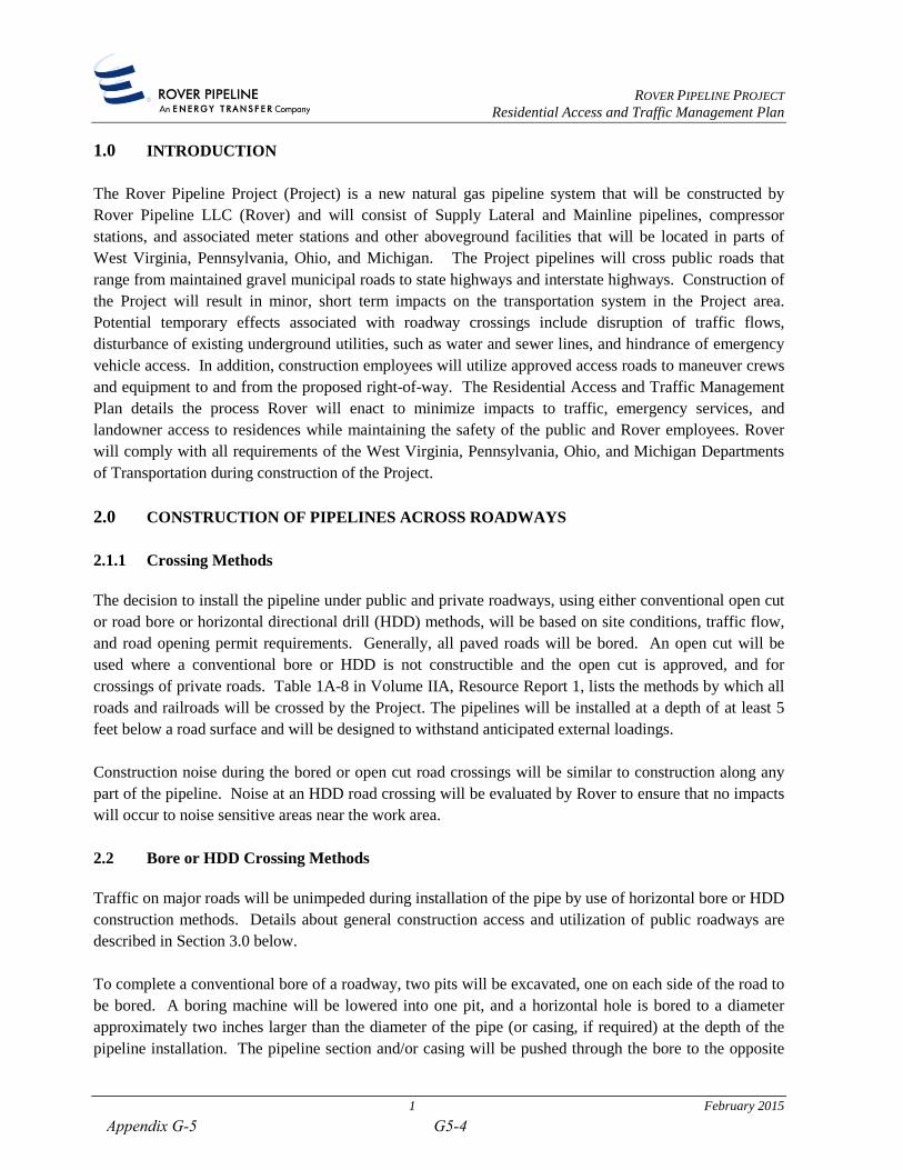
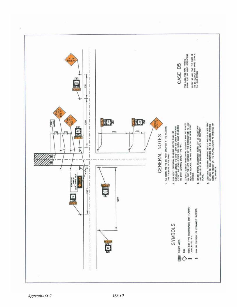
ROVER PIPELINE PROJECT Residential Access and Traffic Management Plan pit. If additional pipeline sections are required to span the length of the bore, they will be welded to the first section of the pipeline in the bore pit before being pushed through the bore. An HDD crossing involves drilling a pilot hole along a prescribed path and then enlarging that hole using reaming tools to achieve a hole large enough to accommodate the pipe. The reaming tools are attached to the drill string at the exit point of the pilot hole and then rotated and drawn back to the drilling rig, thus progressively enlarging the pilot hole with each pass. During this process, drilling fluid consisting of bentonite clay and water is maintained in drilling pits within the construction work area and will be continuously pumped into the hole to remove cuttings and maintain the integrity of the hole between the HDD entry and exit points. Once the hole has been sufficiently enlarged, a prefabricated segment of pipe will be attached behind the reaming tool on the exit side of the crossing and pulled back through the drill hole to the drill rig, completing the crossing. 2.3 Open Cut Crossing 2.3.1 Prior to an Open Cut Crossing Where an open cut is required, two weeks advance notice will be given to area residences and local authorities prior to the cutting of the specific roadway. To minimize traffic delays at open-cut road crossings, Rover will establish detours before initiating an open cut of a road. Appropriate traffic management and signage will be set up and necessary safety measures will be developed in compliance with applicable permits for work in public roadways. Arrangements will be made with local officials to have traffic safety personnel on hand during periods of construction. Provisions will be made for detours or otherwise to permit traffic flow. State-specific requirements for traffic management, including signage, flagging, barrels, etc. are detailed on the attached typical figures. Rover will comply with all applicable state, county, and municipal requirements during construction of the Project. The “One Call” system of each state will be contacted to allow state and local utility operators to verify and mark all underground utilities (e.g., cables, conduits, and pipelines) located within the construction work areas. If any utilities are inadvertently disrupted during construction, Rover will ensure that they are restored as quickly as possible. Rover is not anticipating any open cut crossings of major roadways. Construction work in roadways will be scheduled so as to avoid commuter traffic and schedules for school buses to the greatest extent practicable, and to minimize landowner inconvenience if the road leads to a residence. In addition, steel plates will be maintained on-site to cover the open trench quickly should emergency vehicles need to travel through the work area. 2.3.2 Construction of an Open Cut Crossing Road crossings that will be open cut involve the excavation of a trench across the roadway and will result in a temporary road closure for 4 - 6 hours during the excavation of the roadway. After the pipe is installed, steel plates will be placed on one side of the open excavation to allow the traffic flow to resume
2 February 2015 G5-5 Appendix G-5

ROVER PIPELINE PROJECT Residential Access and Traffic Management Plan through one lane. This will allow the other side of the excavation to be filled with select flowable fill material (i.e. sand and cement mix). Flowable fill is utilized to fill the trench completely and quickly, and it supports the weight-bearing requirements of a roadway and minimizes the chances of voids remaining, which could cause potholes or facilitate road damage in the future. Once the excavation is filled, the steel plates will be moved to the alternate side of the filled roadway and the remaining side will then be filled. The steel plates will remain in place overnight to allow the flowable fill material to harden. After a minimum of 12 hours, the steel plates can be removed and road base material will be placed over the excavated area and a normal traffic pattern can resume. As a contingency, Rover intends to keep excess materials and pumps onsite to ensure the trench can be backfilled immediately after the pipe is installed to minimize the impacts to area traffic. 3.0 Utilization of Roadways during Construction In addition to the traffic impacts caused by the open-cut road crossings, the movement of construction equipment and materials, and the daily commuting of workers to and from the construction work areas, may increase traffic volumes in localized areas throughout the Project area. Project-related construction traffic will typically occur during the early morning hours and evening hours when construction workers commute to the construction work areas. Construction workers will be deployed in various locations along the pipeline such that no single area will experience significant traffic impacts. Access roads utilized during construction are preapproved by FERC, landowners, and the appropriate permitting agencies, and Rover is responsible for ensuring the construction employees utilize only preapproved access roads. Pipeline construction is typically scheduled to take advantage of daylight hours, usually starting in the early morning and ending in the evening (six days a week). Therefore, construction activities will begin before peak commuting hours in the morning and end after peak evening commuting hours. Because construction will move sequentially along the pipeline route, traffic flow impacts that do arise will be temporary on any given section of roadway. Accordingly, Rover does not anticipate significant traffic impacts during construction. To maintain safe conditions, Rover will require its construction contractors to ensure enforcement of local weight restrictions and limitations by its vehicles. Specifically, Rover will require its contractors to obtain road and highway permits and bonding, as required, for the use of public roads to transport construction equipment and materials, especially for any overweight or oversized equipment. Damage to public and private roadways due to construction will be repaired by Rover’s contractors. At points of access to the right-of-way from hard-surfaced roads, a stone pad will be installed as a construction entrance to control dirt tracking onto the highway. Flagging and signage will be utilized as appropriate and in accordance with all applicable regulations if any temporary impacts to traffic are necessary to move equipment across a roadway along the proposed right-of-way.
3 February 2015 Appendix G-5 G5-6

ROVER PIPELINE PROJECT Residential Access and Traffic Management Plan 4.0 Post-Construction Rover is responsible for any roads that are open cut during construction of the Pipeline. Rover will obtain all applicable state, county, and local permits for utilization of and construction across roadways. Rover will enter into Road Use and Management Agreements with all state, county, and municipal regulatory entities to ensure that the roadways utilized during construction of the Project are returned to an as good as or better condition than they were prior to construction. Rover is currently and will continue to communicate with the appropriate agencies and individuals at the state, county, municipal, community, and private levels regarding road construction and post-construction restoration for public and private road crossings.
4 February 2015 G5-7 Appendix G-5

ROVER PIPELINE PROJECT Residential Access and Traffic Management Plan
Traffic Management Plan Typical Drawings West Virginia
February 2015 Appendix G-5 G5-8

G5-9 Appendix G-5
Appendix G-5 G5-10

G5-11 Appendix G-5
Appendix G-5 G5-12

ROVER PIPELINE PROJECT Residential Access and Traffic Management Plan
Traffic Management Plan Typical Drawings Pennsylvania
February 2015 G5-13 Appendix G-5

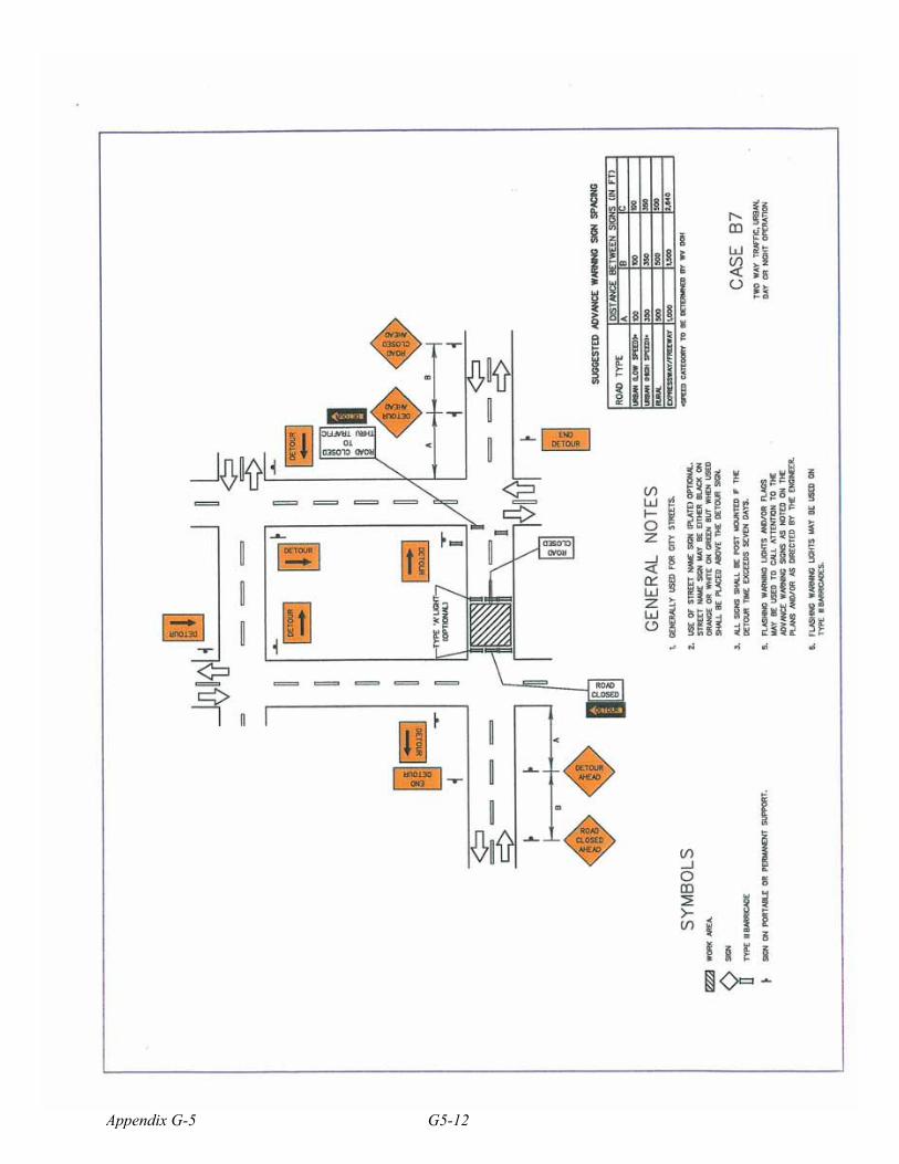
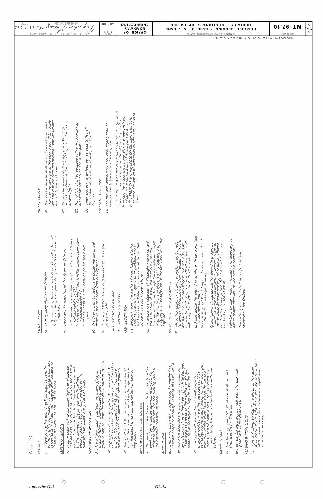
1. Each flagger shall be clearly visible to traffic for a minimum distance of E and shall be in constant communication with all other flaggers.
2. For operations of 15 minutes or less:
3. The buffer space shall be extended so that the two-way traffic taper is placed before a horizontal (or crest vertical) curve to provide adequate sight distance for the flagger and a queue of stopped vehicles.
4. When a shadow vehicle is not used, distance E is measured from end of taper to beginning of work space.
a. The Road Work (W20-1), One Lane Road (W20-4), and Flagger Symbol (W20-7) signs are not required.
b. All channelizing devices may be eliminated if a shadow vehicle is present.
55
Appendix G-5 G5-14
C
B
A
40'
50'
ESee Note 4
H
50'
C
B
A
40'
25'
56
G5-15 Appendix G-5

1. This figure applies for stationary operations where it is not feasible to maintain alternate one direction traffic flow.
2. This setup is to be used during daylight hours only and only on roadways with an ADT of 1500 or less. The PATA may be approved by the District Traffic Engineer for use on other roads.
3. Hours of work should not interfere with rush hour (6:00-9:00 AM and 3:00-6:00 PM) or school bus schedules and the work site must be capable of accommodating emergency vehicles with as little delay as possible.
4. At locations where there are overlapping detours or several detours within the same area, street names may be added to the M4-9 series signs, or signs with different colored arrows may be used to designate different detour routes. The design and application of signs displaying colored arrows shall comply with PennDOT Publication 236.
5. The Road Closed-Local Traffic Only (R11-3A) sign may be used in place of the Road Closed To Thru Traffic (R11-4) sign.
6. This Street To Be Closed For Maintenance Next Week (W23-101) signs should be installed for scheduled work. Install the signs at most appropriate locations.
71
Appendix G-5 G5-16

C
B
A
B
A
A
C
A
A
B
A
A
A
A
A
A
72G5-17 Appendix G-5
ROVER PIPELINE PROJECT Residential Access and Traffic Management Plan
Traffic Management Plan Typical Drawings Ohio
February 2015 Appendix G-5 G5-18

Page 6H - 20 2005 Edition
OMUTCD - English units are preferred.
Notes for Figure 6H-8—Typical Application 8 Road Closure with Off-Site Detour
Guidance:
1. Regulatory traffic control devices should be modified as needed for the duration of the detour.
2. If the road is opened for some distance beyond the intersection and/or there are significant origin/destination points beyond the intersection, the ROAD CLOSED and DETOUR signs on Type III Barricades should be located at the edge of the traveled way.
Option:
3. If the road is closed a short distance beyond the intersection and there are few origin/destination points beyond (for example, a few residences), the Type III Barricade shown in the figure may be moved to the center of the traveled lanes.
Standard:
4. If the barricades are located as in Item 3 above, the ROAD CLOSED and DETOUR signs shall be placed only on the barricade centered in the lane of travel of traffic approaching the closure. The barricade centered in the lane of travel of departing traffic shall not be signed. The barricades in adjacent lanes shall be offset longitudinally from each other an adequate distance in order to permit traffic to travel around the barricades (the barricade in the road user’s lane located in advance of the barricade located left of the center line).
Option: 5. A Route Sign Directional assembly may be placed on the far left corner of the intersection to
augment or replace the one shown on the near right corner.
6. Flashing warning lights and/or flags may be used to call attention to the advance warning signs.
7. Cardinal direction plaques may be used with route signs.
G5-19 Appendix G-5

2005 Edition Page 6H - 21
OMUTCD - English units are preferred.
Figure 6H-8. Road Closure with Off-Site Detour (TA-8)
Á�ÂÄà Å%ÆlÇ�ÅÈÅ+ÉËÊ6ÌÈÍ Å�Î+Ï�Ð�Ñ Ò|Ê�ÓÄÔÏ�Ð�Ñ Õ+Ö Â6×Èà ØÄÅ�Ù+ÅÈÊ�ÓÈÚ ÓËÛÂÄÖÈà ØÄÅ=ÎÝÜÈÙ=Ì�Â6Í ÎlÊ�ÓÄÔÄÞ Â6×Í ÅÄà à Å6×�ßËÂÈÔÈÅ�Î+àÄÎÄÅÈÔ�Ú Óà ØÈÚ ÎáÖ Ú Û�àÈ× Å%â
ã�ä1å(æ çHè:é�êëå(å(éFæ çHè+ì�æ íEî®ï
ðÈñòEóô ñòò(õ ö ÷
ø7òòEóô ð�ù òòòúõ ö ÷
ð�ñ7òEóô ñòòúõ ö ÷
ð�ñ7òEóô ñòòúõ ö ÷
û1ü ò8óô û1ý òòúõ ö ÷
Ç�ÅÈÅHÇ�ÅÈßþÃ Ú Â�ÓlÒ%ÿ â ����Ê�ÓÄÔ��Ú Û�àÈ× Å=Ò%ÿ�Ñ Õ+Ö Â6×Èà ØÄÅHßËÂ6× × ÅÈßþÃÔÈÅ�Î�Ú Û%Ó+ÂÄÖ�Ê�Ó��=ØÈÚ ÂHÇ7à ÊÄà Å��Â6àËà Å=ÎÈÚ Û%Ó6â
Appendix G-5 G5-20
Page 6H - 24 2005 Edition
OMUTCD - English units are preferred.
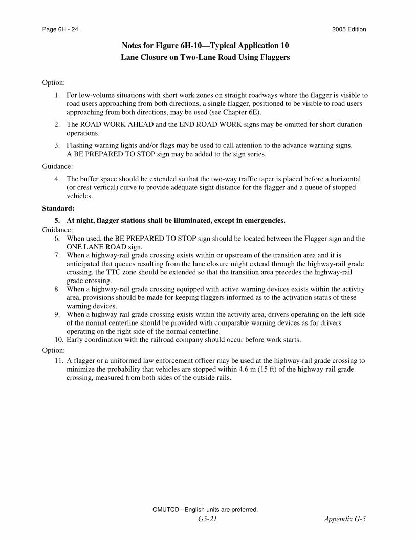
Notes for Figure 6H-10—Typical Application 10 Lane Closure on Two-Lane Road Using Flaggers
Option:
1. For low-volume situations with short work zones on straight roadways where the flagger is visible to road users approaching from both directions, a single flagger, positioned to be visible to road users approaching from both directions, may be used (see Chapter 6E).
2. The ROAD WORK AHEAD and the END ROAD WORK signs may be omitted for short-duration operations.
3. Flashing warning lights and/or flags may be used to call attention to the advance warning signs. A BE PREPARED TO STOP sign may be added to the sign series.
Guidance:
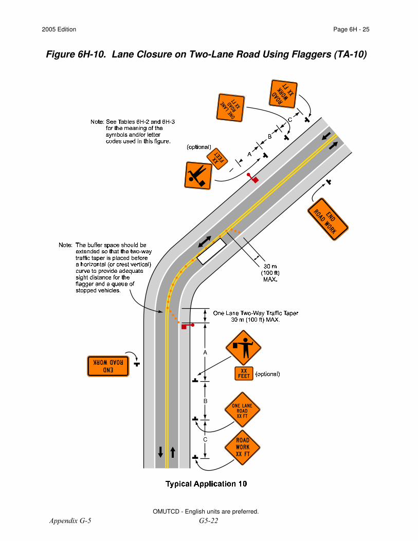
4. The buffer space should be extended so that the two-way traffic taper is placed before a horizontal (or crest vertical) curve to provide adequate sight distance for the flagger and a queue of stopped vehicles.
Standard: 5. At night, flagger stations shall be illuminated, except in emergencies. Guidance:
6. When used, the BE PREPARED TO STOP sign should be located between the Flagger sign and the ONE LANE ROAD sign.
7. When a highway-rail grade crossing exists within or upstream of the transition area and it is anticipated that queues resulting from the lane closure might extend through the highway-rail grade crossing, the TTC zone should be extended so that the transition area precedes the highway-rail grade crossing.
8. When a highway-rail grade crossing equipped with active warning devices exists within the activity area, provisions should be made for keeping flaggers informed as to the activation status of these warning devices.
9. When a highway-rail grade crossing exists within the activity area, drivers operating on the left side of the normal centerline should be provided with comparable warning devices as for drivers operating on the right side of the normal centerline.
10. Early coordination with the railroad company should occur before work starts. Option:
11. A flagger or a uniformed law enforcement officer may be used at the highway-rail grade crossing to minimize the probability that vehicles are stopped within 4.6 m (15 ft) of the highway-rail grade crossing, measured from both sides of the outside rails.
G5-21 Appendix G-5
2005 Edition Page 6H - 25
OMUTCD - English units are preferred.
Figure 6H-10. Lane Closure on Two-Lane Road Using Flaggers (TA-10)
�"�6� ���X�9���0�%�Q� � �V�V�C���%�Q���C���V�%� �0�C����C� �V���%�6���Q��� �C�6�%� ����� ���%� ������ � ��� ��� ��� �V���V�?� �|�%� �%�e�%�0����� �V� ��0���V��� �Q�V�C� �V�Q� �-�V��� �%�Z�6���V� � � �e�V� ����%� ���|� �0�%� ���6� �%���%�%�6�V���6� ���� �V�C�-�V� �e� �V���Q�v� �V�-� ������ �%�%�%�V�-�V�������-���V��������e� �V�%���%�v���V�%� �C� �%�%�
���6� �?�C�9�%�v�C�V�%� �%�f�?���� ��V�����?�"�'¡� �V�%� ���0¢|�6�V�%� �����C�-� ����e��¢����V� �f�V����£ �V�?� �6� � �V��Q�%�6�%�|���Q�6�0� �v� �%� ����� �V�%� �?�
¡%¤�¢�¦¥Q¤%¤b� � �§�¨"©��
� �-�C� � �V���V� �¨
ª
«
� �V�C� � �V�C�V� �
¬ ���0C�V���v�6���%� ®4���f��� ��� ��� ���Q�V���V�¡6¤�¢¯�¦¥e¤%¤v� � �O§�¨�©��
A
B
C
°�±�²|³'´Xµb¶�·¸²|²|¶¦³'´Xµ¹C³ º0»½¼¾
Appendix G-5 G5-22
END
ROAD WORK
END
ROAD WORK
WORK
ROAD
AHEAD
ROAD
ONE LANE
AHEAD
SL
OW
ENGINEERING
ROADWAY
OFFICE OFSTATE OF OHIO DEPARTMENT OF TRANSPORTATION
DATE
12
HIGHWAY - STATIONARY OPERATION
FLAGGER CLOSING 1 LANE OF A 2-LANE
07-18-2014
STANDARD ROADWAY CONSTRUCTION DRAWING
ENGINEER
STDS.
ADMINISTRATOR Soisson
SCD NUMBER
MT-97.10
SL
OW
G20-2-48
G20-2-48
Should
er
Sh
ou
lder
Should
er
Sh
ou
lder
Sh
ou
lder
W20-1-48
Warning Light
Type A
Warning Light
Type A
LE
GE
ND
DIR
EC
TIO
N O
F T
RA
VE
L
TA
BL
E I
IT
AB
LE
I
(SIG
N S
PA
CIN
G)
A2
5’
Max. L
ength
of C
losure =
2000’
25
’
60
57
0
DR
UM
S/C
ON
ES
Sam
e a
s O
pposit
e A
pproach
Lum
inair
e
Fla
gg
er
Lum
inair
e
W20-4-48
W20-7-48
Op
tio
nal
RO
AD
TY
PE
A
DIS
TA
NC
E B
ET
WE
EN
SIG
NS
(F
T)
BC
10
01
00
10
0
350
350
350
50
05
00
50
0
(MP
H)
LIM
IT
SP
EE
D
MIN
.
(D
) (
FT
)
BU
FF
ER
25
15
5
30
200
35
250
40
305
45
36
0
50
42
5
55
49
5
(<
40
MP
H)
Tw
o-L
ane
(4
5-5
0 M
PH
)
Tw
o-L
ane
(5
5-6
0 M
PH
)
Tw
o-L
ane
SH
AD
OW
VE
HIC
LE
WO
RK
AR
EA
50
’-1
00
’A
BC
A1
00
’1
00
’
THIS DRAWING REPLACES MT-97.10 DATED 07-19-2013.
D
(T
yp
ical)
ST
OP
/SL
OW
Paddle
Fla
gger U
sin
g
(S
ee N
ote
s 1
2A
-1
2D
)
Attenuator (
Optional)
Truck-M
ounte
d
G5-23 Appendix G-5
ENGINEERING
ROADWAY
OFFICE OFSTATE OF OHIO DEPARTMENT OF TRANSPORTATION
DATE
22
HIGHWAY - STATIONARY OPERATION
FLAGGER CLOSING 1 LANE OF A 2-LANE
07-18-2014
STANDARD ROADWAY CONSTRUCTION DRAWING
ENGINEER
STDS.
ADMINISTRATOR Soisson
SCD NUMBER
MT-97.10
THIS DRAWING REPLACES MT-97.10 DATED 07-19-2013.
closure is necessary.
(W
20
-5
) s
ig
ns a
re r
eq
uired
wh
en
ev
er a
nig
ht l
an
e
WO
RK
AH
EA
D (
W2
0-1
) sig
ns a
nd
on
th
e L
AN
E C
LO
SE
D A
HE
AD
7.
T
yp
e A
fla
sh
ing
warn
ing
lig
hts
sh
ow
n o
n t
he R
OA
D
FL
AS
HIN
G W
AR
NIN
G L
IGH
TS
speed l
im
it i
s 4
0 m
ph o
r l
ess.
6B
. 36" w
arnin
g s
igns m
ay b
e u
sed w
hen t
he a
pproach
wh
en
sp
ecified
in
th
e p
lan
.
6A
. T
he A
dvis
ory S
peed (
W13-1P
) p
laque s
hall
be u
sed
SIG
NIN
G D
ET
AIL
S
active.
co
vered
du
rin
g t
he p
eriod w
hen b
oth p
rojects a
re
another t
raffic c
ontrol z
one s
hall b
e o
mitted o
r
WO
RK
(G
20
-2
) s
ign
wh
ich
fall
s w
ith
in t
he l
imit
s o
f
confu
sin
g. A
ny R
OA
D W
OR
K A
HE
AD
(W
20-1
) or
EN
D R
OA
D
should b
e a
voided w
here t
he m
essages c
ould b
e
5C
. O
verlap
pin
g o
f s
ig
nin
g f
or a
djacen
t p
ro
jects
ram
ps,
an
d o
n r
oad
way
s e
xitin
g t
he w
ork
lim
its.
these s
igns b
e p
laced
on
th
e m
ain
lin
e, o
n a
ll e
xit
lane c
losures o
f m
ore t
han 1
day. It i
s i
ntended t
hat
5B
. E
ND
RO
AD
WO
RK
(G
20
-2
) s
ign
s a
re o
nly
req
uir
ed
fo
r
entrance r
am
ps o
r r
oadw
ays e
ntering t
he w
ork l
im
its.
5A
. R
OA
D W
OR
K A
HE
AD
(W
20-1) s
igns s
hall
be p
rovid
ed o
n
BA
SIC
SIG
NIN
G
and h
orizontal r
oadw
ay a
lignm
ent.
adequate s
ight d
istance f
or t
he e
xisting v
ertical
w
arning s
igns s
hould b
e a
djusted t
o p
rovide f
or
4.
Th
e l
ocatio
n o
f t
he f
lag
ger s
tatio
n a
nd
th
e a
dv
an
ce
AD
JU
ST
ME
NT
S F
OR
SIG
HT
DIS
TA
NC
E
alig
nm
en
t.
for t
he e
xisting v
ertical a
nd h
orizontal r
oadw
ay
be a
dju
sted
to
pro
vid
e f
or a
deq
uate s
ig
ht d
istan
ce
3C
. T
he l
ocati
on
of t
he a
dv
an
ce w
arn
ing
sig
ns s
ho
uld
min
im
um
of 4
00
’ f
or s
peed
s o
f 5
0 m
ph
or g
reater.
sh
all b
e 2
00
’ f
or s
peed
s o
f 4
5 m
ph
or l
ess a
nd
a
w
ith e
xisting s
igns. M
inim
um
spacing t
o e
xisting s
igns
3B
. S
ign s
pacing s
hould b
e a
djusted t
o a
void c
onflict
greater t
han
1.5
tim
es t
he d
istan
ces s
ho
wn
in
Tab
le I
.
sh
ow
n i
n T
ab
le I
. M
ax
imu
m s
pacin
g s
ho
uld
no
t b
e
3A
. T
he m
inim
um
spacin
g b
etw
een w
ork z
one s
igns i
s
SIG
N L
OC
AT
ION
AN
D S
PA
CIN
G
road s
hall b
e c
losed i
n a
ny o
ne w
ork z
one.
clo
su
res s
hall b
e 2
00
0’.
On
ly
on
e s
id
e o
f t
he
by t
he E
ngin
eer. T
he m
inim
um
length
betw
een
sh
all n
ot b
e m
ore t
han
20
00
’ l
on
g u
nless a
pp
ro
ved
co
mb
in
ed
in
to
on
e w
ork
zo
ne.
Ho
wev
er,
th
e c
lo
su
re
2.
Sev
eral s
mall w
ork
areas c
lo
se t
og
eth
er s
ho
uld
be
LE
NG
TH
OF
CL
OS
UR
E
co
mm
un
icate w
ith
each
oth
er a
t a
ll t
im
es.
op
eratio
n i
s i
n e
ffect.
Th
e f
lag
gers s
hall b
e a
ble t
o
control t
raffic c
ontinuously f
or a
s l
ong a
s a
one l
ane
1. F
laggers, one f
or e
ach d
irection, shall b
e u
sed t
o
FL
AG
GE
RS
:N
OT
ES
area.
b
e u
sed
fo
r s
ig
nin
g o
f s
id
e r
oad
s i
ntersectin
g t
he w
ork
c) T
he F
RE
SH
TA
R a
nd t
he L
OO
SE
GR
AV
EL
sig
ns s
hall
both
S
peed (
W13-1) p
laque e
very h
alf
mil
e p
er C
MS
422.0
9.
b) R
epeat
the L
OO
SE
GR
AV
EL
sig
n w
ith a
35 m
ph A
dvis
ory
b
oth b
e u
sed i
n a
dvance o
f t
he c
hip s
eal o
peration.
a) T
he L
OO
SE
GR
AV
EL
(W
8-7
) a
nd
FR
ES
H T
AR
(W
21
-2
) s
ign
s s
hall
in
co
rp
orated
in
th
e a
dv
an
ced
warn
in
g a
rea.
13. F
or c
hip s
eal o
perations, additional s
igning s
hall b
e
CH
IP S
EA
L O
PE
RA
TIO
NS
E
ngineer.
t
he s
hadow
vehicle s
how
n w
hen a
pproved b
y t
he
12
D.
Oth
er p
ro
tectiv
e d
ev
ices m
ay
be u
sed
in
lieu
of
a
ttenuator w
hen c
alled f
or i
n t
he p
lans.
12C
. T
he v
ehic
le s
hall
be e
quip
ped w
ith a
truck-m
ounte
d
strobe light(s).
i
ntensity y
ellow
rotating, flashing, oscillating, or
12B
. T
he s
hadow
vehic
le s
hall
be e
quip
ped w
ith a
hig
h-
are n
ot in
th
e w
ork
area.
sh
all b
e r
em
ov
ed
fro
m t
he p
av
em
en
t w
hen
ver w
ork
ers
wh
en
ev
er w
ork
ers a
re i
n t
he w
ork
area.
Th
is v
eh
icle
12
A.
Th
e s
had
ow
veh
icle
sh
all
be i
n p
lace a
nd
un
occu
pie
d
SH
AD
OW
VE
HIC
LE
ap
pro
val o
f t
he E
ng
in
eer.
Th
e m
eth
od
of c
on
tro
l s
hall b
e s
ub
ject t
o t
he
assure p
roper l
ocation f
or t
he t
raffic c
onditions.
E
xisting S
TO
P s
igns s
hall b
e r
elocated a
s n
ecessary t
o
barric
ad
es,
see S
CD
MT
-1
01
.60
.
C
onstr
ucti
on D
raw
ings (
SC
Ds M
T-97.1
1 o
r M
T-97.1
2. F
or
the d
rivew
ay o
r c
ross h
ighw
ay, as s
how
n i
n S
tandard
located 2
5’ b
eyond t
he p
rojected p
avem
ent e
dges o
f
D
rum
s (
cones) p
laced a
cross t
he c
losed l
ane s
hall b
e
i
ntersection a
nd m
ajor d
rivew
ay.
b) P
ro
vid
e a
n a
dd
itio
nal f
lag
ger a
t e
very
pu
blic s
treet
o
r b
arricad
es, an
d/o
r
a) P
lace a
cro
ss t
he c
lo
sed
lan
e,
eith
er t
hree d
ru
ms (
co
nes)
no
t r
ead
y f
or t
raffic.
Th
e C
on
tracto
r s
hall:
m
ovem
ents a
nd t
o k
eep v
ehicles o
ff o
f n
ew
pavem
ent
an
d m
ajo
r d
riv
es a
s n
ecessary
to
prev
en
t w
ro
ng
-w
ay
to
co
ntro
l traffic en
terin
g fro
m in
tersectin
g streets
11
. W
ith
in
th
e l
en
gth
of c
lo
su
re,
pro
visio
n s
hall b
e m
ad
e
INT
ER
SE
CT
ION
/ D
RIV
EW
AY
AC
CE
SS
E
ngineer.
s
hielding s
hall b
e a
djusted t
o t
he s
atisfaction o
f t
he
w
hen t
he l
ighting i
s i
n p
lace. L
ight p
lacem
ent a
nd
E
ngineer s
hall d
rive t
hrough t
he w
orksite e
ach n
ight
th
e e
lim
in
atio
n o
f g
lare,
th
e C
on
tracto
r a
nd
th
e
10B
. T
o e
nsure t
he a
dequacy o
f f
loodlight p
lacem
ent a
nd
adjacent to each flagger station.
l
ighting i
s a
cceptable. L
um
inaires s
hall b
e l
ocated
sh
all b
e p
ro
vid
ed
at n
ig
ht.
Use o
f p
ortab
le f
lo
od
10
A.
Ad
eq
uate a
rea i
llu
min
atio
n o
f e
ach
flag
ger s
tatio
n
AR
EA
IL
LU
MIN
AT
ION
9A
. (
inte
nti
onall
y b
lank)
(RE
SE
RV
ED
FO
R F
UT
UR
E U
SE
)
p
aved s
houlder.
8D
. A
min
imum
of t
wo d
rum
s s
hall
be u
sed t
o c
lose t
he
d
rum
s t
o p
revent t
hem
from
blow
ing o
ver.
8C
. P
ro
visio
ns s
hall b
e m
ad
e t
o s
tab
ilize t
he c
on
es a
nd
tapers.
c
) U
se o
f c
ones a
t n
ight s
hall b
e p
rohibited a
long
a m
inim
um
height o
f 4
2".
b) C
on
es u
sed
fo
r n
ig
httim
e t
raffic c
on
tro
l s
hall h
av
e
m
inim
um
height o
f 2
8".
a
) C
ones u
sed f
or d
aytim
e t
raffic c
ontrol s
hall h
ave a
8B
. C
ones m
ay b
e s
ubstituted f
or d
rum
s a
s f
ollow
s:
to-center.
b
) S
pacing a
long t
he a
pproach t
aper s
hall b
e 1
0’ c
enter-
a
) S
pacing a
long t
he c
losure s
hall b
e 4
0’ c
enter-to-center.
8A
. D
ru
m s
pacin
g s
hall
be a
s f
oll
ow
s:
DR
UM
S /
CO
NE
S
Appendix G-5 G5-24

ROVER PIPELINE PROJECT Residential Access and Traffic Management Plan
Traffic Management Plan Typical Drawings
Michigan
February 2015 G5-25 Appendix G-5
SH
OU
LD
ER
SH
OU
LD
ER
D2
D
SIGN PLACEMENT
IS THE SAME FOR
BOTH DIRECTIONS
SIGN = 136 ft2 - TYPE B
INJURE /
KILL A
WORKER
$7500 +
15 YEARS
INJURE /
KILL A
WORKER
$7500 +
15 YEARS
D
TO PROTECT
FINES DOUBLED IN
WORK ZONES
HIGHWAY WORKERS
R5-18a
D
TO PROTECT
FINES DOUBLED IN
WORK ZONES
HIGHWAY WORKERS
R5-18a
REMAINING SEQUENCE
SIGNING PER
APPROPRIATE TYPICAL
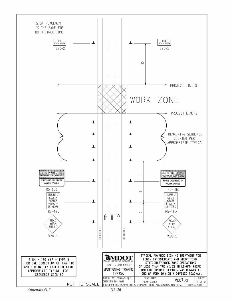
TYPICAL ADVANCE SIGNING TREATMENT FOR
LONG, INTERMEDIATE AND SHORT TERM
STATIONARY WORK ZONE OPERATIONS
OF LESS THAN TWO MILES IN LENGTH WHERE
TRAFFIC CONTROL DEVICES MAY REMAIN AT
END OF WORK DAY ON A DIVIDED ROADWAY.
CON:AE:djf
08/15/2007
ROAD WORK
END
G20-2
PROJECT LIMITS
PROJECT LIMITS
WORK ZONE
ROAD WORK
END
G20-2
R5-18b R5-18b
1 2 BMM M0070a
W20-1
ROAD
WORK
AHEAD
W20-1
ROAD
WORK
AHEAD
JUNE 2006
FOR ONE DIRECTION OF TRAFFIC
W20-1 QUANTITY INCLUDED WITH
APPROPRIATE TYPICAL FOR
SEQUENCE SIGNING
PW RD/TS/Typicals/Signs/MT NON FWY/M0070a.dgn
MAINTAINING TRAFFIC
TYPICAL
SHEET
Michigan Department of Transportation
FILE:
OF
TRAFFIC AND SAFETY
PLAN DATE:
DRAWN BY:
CHECKED BY:
REV. NOT TO SCALE
Appendix G-5 G5-26

NOTES
SIGN SIZES
32. THESE SIGNS SHALL BE LEFT IN PLACE AT THEIR PRESCRIBED LOCATIONS FOR THE DURATION OF THE PROJECT AND
UNTIL ALL TEMPORARY TRAFFIC CONTROL HAS BEEN REMOVED.
35. THESE SIGNS ARE INTENDED TO BE USED WITHIN THE LIMITS OF THE TEMPORARY SEQUENCE SIGNING AS IS SHOWN ON
1 0F 2. THESE SIGNS ARE NOT TO BE INTERMINGLED WITH ANY OTHER TEMPORARY SEQUENCE SIGNING EXCEPT AS
SHOWN.
TYPICAL ADVANCE SIGNING TREATMENT FOR
LONG, INTERMEDIATE AND SHORT TERM
STATIONARY WORK ZONE OPERATIONS
OF LESS THAN TWO MILES IN LENGTH WHERE
TRAFFIC CONTROL DEVICES MAY REMAIN AT
END OF WORK DAY ON A DIVIDED ROADWAY.
CON:AE:djf
08/15/2007
2 2 BMM M0070a
30. THE APPROPRIATE ADVANCE SIGNING SEQUENCE(S), (M0030a THROUGH M0080a) SHALL BE USED ON ALL PROJECTS.
G20-2 - 48" x 24"
R5-18a - 96" x 60"
R5-18b - 48" x 60"
W20-1 - 48" x 48"
JUNE 2006
PW RD/TS/Typicals/Signs/MT NON FWY/M0070a.dgn
MAINTAINING TRAFFIC
TYPICAL
SHEET
Michigan Department of Transportation
FILE:
OF
TRAFFIC AND SAFETY
PLAN DATE:
DRAWN BY:
CHECKED BY:
REV. NOT TO SCALE
G5-27 Appendix G-5
SH
OU
LD
ER
SH
OU
LD
ER
2D
DD
SIGN PLACEMENT
IS THE SAME FOR
BOTH DIRECTIONS
TRAFFIC
FINES
DOUBLED
IN WORK
ZONES
R5-18
D
REMAINING SEQUENCE
SIGNING PER
APPROPRIATE TYPICAL
TRAFFIC
FINES
DOUBLED
IN WORK
ZONES
R5-18
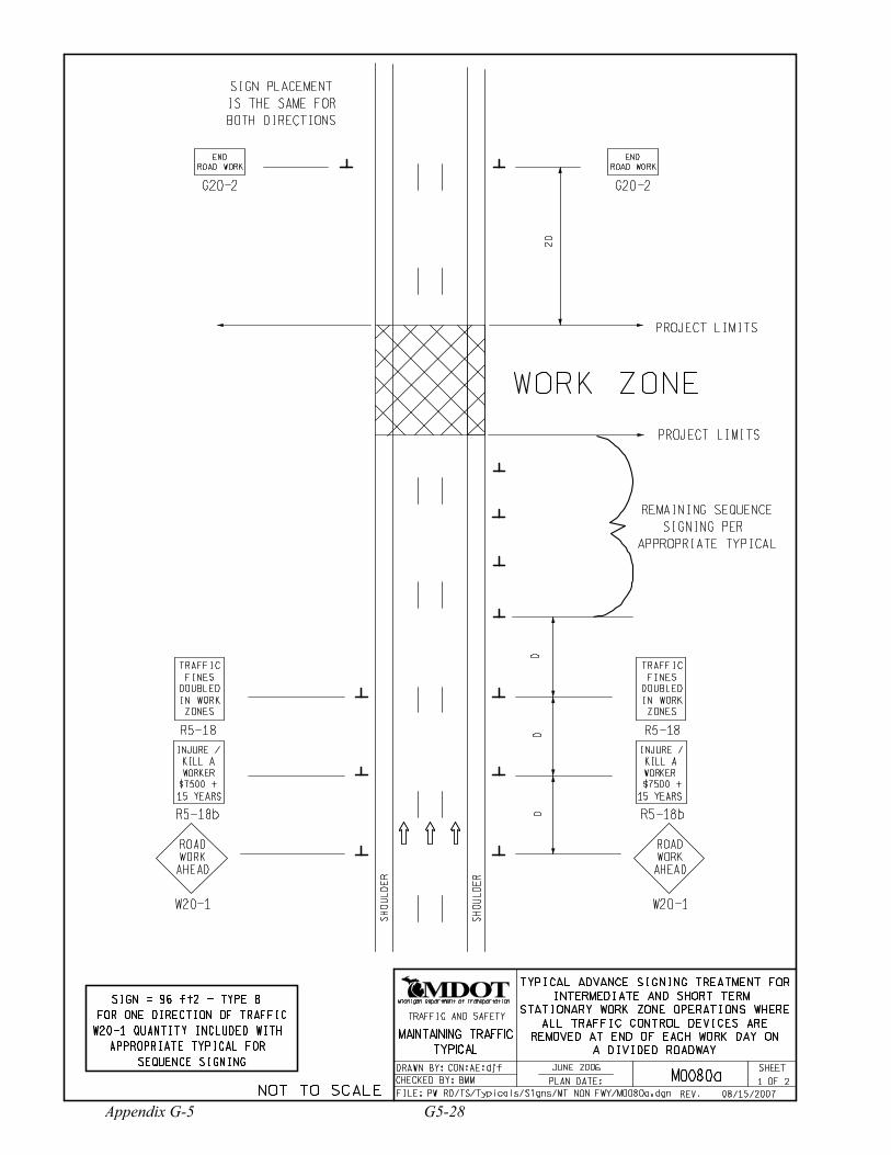
TYPICAL ADVANCE SIGNING TREATMENT FOR
INTERMEDIATE AND SHORT TERM
STATIONARY WORK ZONE OPERATIONS WHERE
ALL TRAFFIC CONTROL DEVICES ARE
REMOVED AT END OF EACH WORK DAY ON
A DIVIDED ROADWAY
CON:AE:djf
ROAD WORK
END
G20-2
PROJECT LIMITS
PROJECT LIMITS
WORK ZONE
R5-18b
INJURE /
KILL A
WORKER
$7500 +
15 YEARS
R5-18b
INJURE /
KILL A
WORKER
$7500 +
15 YEARS
1 2 BMM M0080a
ROAD WORK
END
G20-2
W20-1
ROAD
WORK
AHEAD
W20-1
ROAD
WORK
AHEAD
JUNE 2006
SIGN = 96 ft2 - TYPE B
FOR ONE DIRECTION OF TRAFFIC
W20-1 QUANTITY INCLUDED WITH
APPROPRIATE TYPICAL FOR
SEQUENCE SIGNING
PW RD/TS/Typicals/Signs/MT NON FWY/M0080a.dgn 08/15/2007
MAINTAINING TRAFFIC
TYPICAL
SHEET
Michigan Department of Transportation
FILE:
OF
TRAFFIC AND SAFETY
PLAN DATE:
DRAWN BY:
CHECKED BY:
REV. NOT TO SCALE
Appendix G-5 G5-28

NOTES
SIGN SIZES
35. THESE SIGNS ARE INTENDED TO BE USED WITHIN THE LIMITS OF THE TEMPORARY SEQUENCE SIGNING AS IS SHOWN ON
1 0F 2. THESE SIGNS ARE NOT TO BE INTERMINGLED WITH ANY OTHER TEMPORARY SEQUENCE SIGNING EXCEPT AS
SHOWN.
TYPICAL ADVANCE SIGNING TREATMENT FOR
INTERMEDIATE AND SHORT TERM
STATIONARY WORK ZONE OPERATIONS WHERE
ALL TRAFFIC CONTROL DEVICES ARE
REMOVED AT END OF EACH WORK DAY ON
A DIVIDED ROADWAY
CON:AE:djf
2 2 BMM M0080a
G20-2 - 48" x 24"
R5-18 - 48" x 60"
R5-18b - 48" x 60"
W20-1 - 48" x 48"
30. THE APPROPRIATE ADVANCE SIGNING SEQUENCE(S), (M0030a THROUGH M0080a) SHALL BE USED ON ALL PROJECTS.
JUNE 2006
PW RD/TS/Typicals/Signs/MT NON FWY/M0080a.dgn 08/15/2007
MAINTAINING TRAFFIC
TYPICAL
SHEET
Michigan Department of Transportation
FILE:
OF
TRAFFIC AND SAFETY
PLAN DATE:
DRAWN BY:
CHECKED BY:
REV. NOT TO SCALE
G5-29 Appendix G-5

W20-4
ONE LANE
ROAD
AHEAD
W20-7a
W20-1
ROAD
WORK
AHEAD
DD
DD
D
D
D
D
W20-7a
W20-4
ONE LANE
ROAD
AHEAD
SH
OU
LD
ER
SH
OU
LD
ER
WO
RK
AREA
VA
RIE
S
KEY
TYPICAL TEMPORARY TRAFFIC CONTROL FOR
A TWO-LANE TWO-WAY ROADWAY WHERE ONE
LANE IS CLOSED UTILIZING TRAFFIC
REGULATORS, NO SPEED REDUCTION
100 ft T
O
200 ft
50 ft TO
100 ft MAXIMUM
PLUS ADDITIONAL R2-1’s
THROUGHOUT WORK AREA
PLACE THROUGHOUT WORK AREA AS
INDICATED AND AFTER ALL MAJOR
CROSSROADS IF PERMANENT SIGNS
ARE NOT IN PLACE.
PLACE THROUGHOUT WORK AREA AS
INDICATED AND AFTER ALL MAJOR
CROSSROADS IF PERMANENT SIGNS
ARE NOT IN PLACE.
D
D
WORK
ZONE
BEGINS
R5-18c
WORK
ZONE
BEGINS
R5-18c
END
ROAD WORK
END
ROAD WORK
SPEED
LIMIT
R2-1
XX
SPEED
LIMIT
R2-1
XX
SPEED
LIMIT
R2-1
XX
SPEED
LIMIT
R2-1
XX
CON:AE:djf
CHANNELIZING DEVICES
LIGHTED ARROW PANEL
(CAUTION MODE)
TRAFFIC REGULATOR
TRAFFIC FLOW
1 2 BMM M0140a
PW RD/TS/Typicals/Signs/MT NON FWY/M0140a.dgn
SIGN = 200 ft2 - TYPE B
100’
JUNE 2006
W20-1
ROAD
WORK
AHEAD
W3-4
BE
PREPARED
TO STOP
PLACE THIS SIGN ALONG WITH THE
ADVANCE WORK ZONE SIGNING AS
DEPICTED ON THE APPROPRIATE
TYPICAL M0030a-M0080a.
REFLECTS EXISTING
SPEED LIMIT
PLACE THIS SIGN ALONG WITH THE
ADVANCE WORK ZONE SIGNING AS
DEPICTED ON THE APPROPRIATE
TYPICAL M0030a-M0080a.
W3-4
BE
PREPARED
TO STOP
08/17/2007
MAINTAINING TRAFFIC
TYPICAL
SHEET
Michigan Department of Transportation
FILE:
OF
TRAFFIC AND SAFETY
PLAN DATE:
DRAWN BY:
CHECKED BY:
REV. NOT TO SCALE
Appendix G-5 G5-30
9. ALL TRAFFIC REGULATORS SHALL BE PROPERLY TRAINED AND SUPERVISED.
10. ALL TRAFFIC REGULATORS’ CONDUCT, THEIR EQUIPMENT, AND TRAFFIC REGULATING PROCEDURES SHALL CONFORM
TO THE CURRENT EDITION OF THE MICHIGAN MANUAL OF UNIFORM TRAFFIC CONTROL DEVICES (MMUTCD) AND THE
CURRENT EDITION OF THE MDOT HANDBOOK ENTITLED "TRAFFIC REGULATORS INSTRUCTION MANUAL."
11. WHEN TRAFFIC REGULATING IS ALLOWED DURING THE HOURS OF DARKNESS, APPROPRIATE LIGHTING SHALL BE
PROVIDED TO SUFFICIENTLY ILLUMINATE THE TRAFFIC REGULATOR’S STATIONS.
13. WHEN INTERSECTING ROADS OR SIGNIFICANT TRAFFIC GENERATORS (SHOPPING CENTERS, MOBILE HOME PARKS, ETC.)
OCCUR WITHIN THE ONE-LANE TWO-WAY OPERATION, INTERMEDIATE TRAFFIC REGULATORS AND APPROPRIATE
SIGNING SHALL BE PLACED AT THESE LOCATIONS.
15. THE HAND HELD (PADDLE) SIGNS REQUIRED BY THE MMUTCD TO CONTROL TRAFFIC WILL BE PAID FOR AS PART OF
FLAG CONTROL.
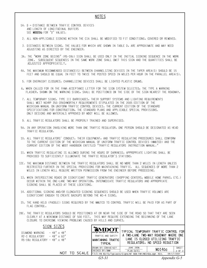
TYPICAL TEMPORARY TRAFFIC CONTROL FOR
A TWO-LANE TWO-WAY ROADWAY WHERE ONE
LANE IS CLOSED UTILIZING TRAFFIC
REGULATORS, NO SPEED REDUCTION
9A. IN ANY OPERATION INVOLVING MORE THAN ONE TRAFFIC REGULATOR, ONE PERSON SHOULD BE DESIGNATED AS HEAD
TRAFFIC REGULATOR.
SIGN SIZES
THE MAXIMUM DISTANCE BETWEEN THE TRAFFIC REGULATORS SHALL BE NO MORE THAN 2 MILES IN LENGTH UNLESS
RESTRICTED FURTHER IN THE SPECIAL PROVISIONS FOR MAINTAINING TRAFFIC. ALL SEQUENCES OF MORE THAN 2
MILES IN LENGTH WILL REQUIRE WRITTEN PERMISSION FROM THE ENGINEER BEFORE PROCEEDING.
12E.
28E. THE TRAFFIC REGULATORS SHOULD BE POSITIONED AT OR NEAR THE SIDE OF THE ROAD SO THAT THEY ARE SEEN
CLEARLY AT A MINIMUM DISTANCE OF 500 FEET. THIS MAY REQUIRE EXTENDING THE BEGINNING OF THE LANE
CLOSURE TO OVERCOME VIEWING PROBLEMS CAUSED BY HILLS AND CURVES.
2. ALL NON-APPLICABLE SIGNING WITHIN THE CIA SHALL BE MODIFIED TO FIT CONDITIONS, COVERED OR REMOVED.
DISTANCES BETWEEN SIGNS, THE VALUES FOR WHICH ARE SHOWN IN TABLE D, ARE APPROXIMATE AND MAY NEED
ADJUSTING AS DIRECTED BY THE ENGINEER.
3.
FOR OVERNIGHT CLOSURES, CHANNELIZING DEVICES SHALL BE LIGHTED PLASTIC DRUMS.5.
3A. THE "WORK ZONE BEGINS" (R5-18c) SIGN SHALL BE USED ONLY IN THE INITIAL SIGNING SEQUENCE IN THE WORK
ZONE. SUBSEQUENT SEQUENCES IN THE SAME WORK ZONE SHALL OMIT THIS SIGN AND THE QUANTITIES SHALL BE
ADJUSTED APPROPRIATELY.
7. ALL TEMPORARY SIGNS, TYPE III BARRICADES, THEIR SUPPORT SYSTEMS AND LIGHTING REQUIREMENTS
SHALL MEET NCHRP 350 CRASHWORTHLY REQUIREMENTS STIPULATED IN THE 2005 EDITION OF THE
MICHIGAN MANUAL ON UNIFORM TRAFFIC CONTROL DEVICES, THE CURRENT EDITION OF THE STANDARD
SPECIFICATIONS FOR CONSTRUCTION, THE STANDARD PLANS AND APPLICABLE SPECIAL PROVISIONS.
ONLY DESIGNS AND MATERIALS APPROVED BY MDOT WILL BE ALLOWED.
CON:AE:djf
BMM M0140a
PW RD/TS/Typicals/Signs/MT NON FWY/M0140a.dgn
2 2
R2-1 REGULATORY - 48" x 60"
R5-18c REGULATORY - 48" x 48"
DIAMOND WARNING - 48" x 48"
JUNE 2006
4A. THE MAXIMUM RECOMMENDED DISTANCE(S) BETWEEN CHANNELIZING DEVICES IN THE TAPER AREA(S) SHOULD BE 15
FEET AND SHOULD BE EQUAL IN FEET TO TWICE THE POSTED SPEED IN MILES PER HOUR IN THE PARALLEL AREA(S).
1H.
M0020aSEE FOR "D" VALUES.
D = DISTANCE BETWEEN TRAFFIC CONTROL DEVICES
AND LENGTH OF LONGITUDINAL BUFFERS
NOTES
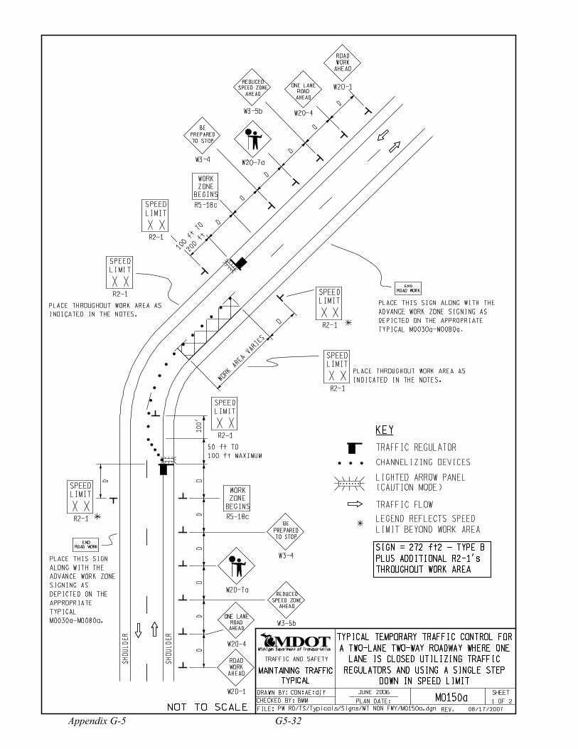
14. ADDITIONAL SIGNING AND/OR ELONGATED SIGNING SEQUENCES SHOULD BE USED WHEN TRAFFIC VOLUMES ARE
SIGNIFICANT ENOUGH TO CREATE BACKUPS BEYOND THE W3-4 SIGNS.
08/17/2007
6. WHEN CALLED FOR IN THE FHWA ACCEPTANCE LETTER FOR THE SIGN SYSTEM SELECTED, THE TYPE A WARNING
FLASHER, SHOWN ON THE WARNING SIGNS, SHALL BE POSITIONED ON THE SIDE OF THE SIGN NEAREST THE ROADWAY.
MAINTAINING TRAFFIC
TYPICAL
SHEET
Michigan Department of Transportation
FILE:
OF
TRAFFIC AND SAFETY
PLAN DATE:
DRAWN BY:
CHECKED BY:
REV. NOT TO SCALE
G5-31 Appendix G-5
W20-4
ONE LANE
ROAD
AHEAD
W20-7a
DD
DD
D
D
D
D
D
D
W20-7a
W20-4
ONE LANE
ROAD
AHEAD
SH
OU
LD
ER
SH
OU
LD
ER
WO
RK
AREA
VA
RIE
S
KEY
D
D
LEGEND REFLECTS SPEED
LIMIT BEYOND WORK AREA
100 ft TO
200 ft
50 ft TO
100 ft MAXIMUM
D
WORK
ZONE
BEGINS
R5-18c
D
WORK
ZONE
BEGINS
R5-18c
END
ROAD WORK
END
ROAD WORK
SPEED
LIMIT
R2-1
XX
SPEED
LIMIT
R2-1
XXSPEED
LIMIT
R2-1
XX
SPEED
LIMIT
R2-1
XX
SPEED
LIMIT
R2-1
XX
SPEED
LIMIT
R2-1
XX
REDUCED
AHEAD
W3-5b
SPEED ZONE
REDUCED
AHEAD
W3-5b
SPEED ZONE
SIGN = 272 ft2 - TYPE B
PLUS ADDITIONAL R2-1’s
THROUGHOUT WORK AREA
CON:AE:djf
TYPICAL TEMPORARY TRAFFIC CONTROL FOR
A TWO-LANE TWO-WAY ROADWAY WHERE ONE
LANE IS CLOSED UTILIZING TRAFFIC
REGULATORS AND USING A SINGLE STEP
DOWN IN SPEED LIMIT
CHANNELIZING DEVICES
LIGHTED ARROW PANEL
(CAUTION MODE)
TRAFFIC REGULATOR
TRAFFIC FLOW
1 2 BMM M0150a
PW RD/TS/Typicals/Signs/MT NON FWY/M0150a.dgn
100’
JUNE 2006
W20-1
ROAD
WORK
AHEAD
W3-4
BE
PREPARED
TO STOP
PLACE THROUGHOUT WORK AREA AS
INDICATED IN THE NOTES.
PLACE THIS SIGN ALONG WITH THE
ADVANCE WORK ZONE SIGNING AS
DEPICTED ON THE APPROPRIATE
TYPICAL M0030a-M0080a.
PLACE THROUGHOUT WORK AREA AS
INDICATED IN THE NOTES.
W3-4
BE
PREPARED
TO STOP
PLACE THIS SIGN
ALONG WITH THE
ADVANCE WORK ZONE
SIGNING AS
DEPICTED ON THE
APPROPRIATE
TYPICAL
M0030a-M0080a.
W20-1
ROAD
WORK
AHEAD
08/17/2007
MAINTAINING TRAFFIC
TYPICAL
SHEET
Michigan Department of Transportation
FILE:
OF
TRAFFIC AND SAFETY
PLAN DATE:
DRAWN BY:
CHECKED BY:
REV. NOT TO SCALE
Appendix G-5 G5-32

NOTES
2. ALL NON-APPLICABLE SIGNING WITHIN THE CIA SHALL BE MODIFIED TO FIT CONDITIONS, COVERED OR REMOVED.
FOR OVERNIGHT CLOSURES, CHANNELIZING DEVICES SHALL BE LIGHTED PLASTIC DRUMS.5.
9. ALL TRAFFIC REGULATORS SHALL BE PROPERLY TRAINED AND SUPERVISED.
DISTANCES BETWEEN SIGNS, THE VALUES FOR WHICH ARE SHOWN IN TABLE D, ARE APPROXIMATE AND MAY NEED
ADJUSTING AS DIRECTED BY THE ENGINEER.
3.
10. ALL TRAFFIC REGULATORS’ CONDUCT, THEIR EQUIPMENT, AND TRAFFIC REGULATING PROCEDURES SHALL CONFORM
TO THE CURRENT EDITION OF THE MICHIGAN MANUAL OF UNIFORM TRAFFIC CONTROL DEVICES (MMUTCD) AND THE
CURRENT EDITION OF THE MDOT HANDBOOK ENTITLED "TRAFFIC REGULATORS INSTRUCTION MANUAL."
11. WHEN TRAFFIC REGULATING IS ALLOWED DURING THE HOURS OF DARKNESS, APPROPRIATE LIGHTING SHALL BE
PROVIDED TO SUFFICIENTLY ILLUMINATE THE TRAFFIC REGULATOR’S STATIONS.
13. WHEN INTERSECTING ROADS OR SIGNIFICANT TRAFFIC GENERATORS (SHOPPING CENTERS, MOBILE HOME PARKS, ETC.)
OCCUR WITHIN THE ONE-LANE TWO-WAY OPERATION, INTERMEDIATE TRAFFIC REGULATORS AND APPROPRIATE
SIGNING SHALL BE PLACED AT THESE LOCATIONS.
15. THE HAND HELD (PADDLE) SIGNS REQUIRED BY THE MMUTCD TO CONTROL TRAFFIC WILL BE PAID FOR AS PART OF
FLAG CONTROL.
9A. IN ANY OPERATION INVOLVING MORE THAN ONE TRAFFIC REGULATOR, ONE PERSON SHOULD BE DESIGNATED AS HEAD
TRAFFIC REGULATOR.
SIGN SIZES
THE MAXIMUM DISTANCE BETWEEN THE TRAFFIC REGULATORS SHALL BE NO MORE THAN 2 MILES IN LENGTH UNLESS
RESTRICTED FURTHER IN THE SPECIAL PROVISIONS FOR MAINTAINING TRAFFIC. ALL SEQUENCES OF MORE THAN 2
MILES IN LENGTH WILL REQUIRE WRITTEN PERMISSION FROM THE ENGINEER BEFORE PROCEEDING.
12E.
28E. THE TRAFFIC REGULATORS SHOULD BE POSITIONED AT OR NEAR THE SIDE OF THE ROAD SO THAT THEY ARE SEEN
CLEARLY AT A MINIMUM DISTANCE OF 500 FEET. THIS MAY REQUIRE EXTENDING THE BEGINNING OF THE LANE
CLOSURE TO OVERCOME VIEWING PROBLEMS CAUSED BY HILLS AND CURVES.
DIAMOND WARNING - 48" x 48"
RECTANGULAR REGULATORY - 48" x 60"
3A. THE "WORK ZONE BEGINS" (R5-18c) SIGN SHALL BE USED ONLY IN THE INITIAL SIGNING SEQUENCE IN THE WORK
ZONE. SUBSEQUENT SEQUENCES IN THE SAME WORK ZONE SHALL OMIT THIS SIGN AND THE QUANTITIES SHALL BE
ADJUSTED APPROPRIATELY.
TYPICAL TEMPORARY TRAFFIC CONTROL FOR
A TWO-LANE TWO-WAY ROADWAY WHERE ONE
LANE IS CLOSED UTILIZING TRAFFIC
REGULATORS AND USING A SINGLE STEP
DOWN IN SPEED LIMIT
CON:AE:djf
7. ALL TEMPORARY SIGNS, TYPE III BARRICADES, THEIR SUPPORT SYSTEMS AND LIGHTING REQUIREMENTS
SHALL MEET NCHRP 350 CRASHWORTHLY REQUIREMENTS STIPULATED IN THE 2005 EDITION OF THE
MICHIGAN MANUAL ON UNIFORM TRAFFIC CONTROL DEVICES, THE CURRENT EDITION OF THE STANDARD
SPECIFICATIONS FOR CONSTRUCTION, THE STANDARD PLANS AND APPLICABLE SPECIAL PROVISIONS.
ONLY DESIGNS AND MATERIALS APPROVED BY MDOT WILL BE ALLOWED.
16B. WHEN REDUCED SPEED LIMITS ARE UTILIZED IN THE WORK AREA, ADDITIONAL SPEED LIMIT SIGNS RETURNING
TRAFFIC TO ITS NORMAL SPEED SHALL BE PLACED BEYOND THE LIMITS OF THE REDUCED SPEED AS INDICATED.
16E. WHEN EXISTING SPEED LIMITS ARE REDUCED MORE THAN 10 MPH, THE SPEED LIMIT SHALL BE STEPPED DOWN IN NO
MORE THAN 10 MPH INCREMENTS.
2 2 BMM M0150a
PW RD/TS/Typicals/Signs/MT NON FWY/M0150a.dgn
R5-18c REGULATORY - 48" x 48" JUNE 2006
16A. ADDITIONAL SPEED LIMIT SIGNS REFLECTING THE REDUCED SPEED SHALL BE PLACED AFTER EACH MAJOR
CROSSROAD THAT INTERSECTS THE WORK AREA WHERE THE REDUCED SPEED IS IN EFFECT, AND AT INTERVALS
ALONG THE ROADWAY SUCH THAT NO SPEED LIMIT SIGNS REFLECTING THE REDUCED SPEED ARE MORE THAN
TWO MILES APART.
4A. THE MAXIMUM RECOMMENDED DISTANCE(S) BETWEEN CHANNELIZING DEVICES IN THE TAPER AREA(S) SHOULD BE 15
FEET AND SHOULD BE EQUAL IN FEET TO TWICE THE POSTED SPEED IN MILES PER HOUR IN THE PARALLEL AREA(S).
14. ADDITIONAL SIGNING AND/OR ELONGATED SIGNING SEQUENCES SHOULD BE USED WHEN TRAFFIC VOLUMES ARE
SIGNIFICANT ENOUGH TO CREATE BACKUPS BEYOND THE W3-4 SIGNS.
1H.
M0020aSEE FOR "D" VALUES.
D = DISTANCE BETWEEN TRAFFIC CONTROL DEVICES
AND LENGTH OF LONGITUDINAL BUFFERS
08/17/2007
6. WHEN CALLED FOR IN THE FHWA ACCEPTANCE LETTER FOR THE SIGN SYSTEM SELECTED, THE TYPE A WARNING
FLASHER, SHOWN ON THE WARNING SIGNS, SHALL BE POSITIONED ON THE SIDE OF THE SIGN NEAREST THE ROADWAY.
MAINTAINING TRAFFIC
TYPICAL
SHEET
Michigan Department of Transportation
FILE:
OF
TRAFFIC AND SAFETY
PLAN DATE:
DRAWN BY:
CHECKED BY:
REV. NOT TO SCALE
G5-33 Appendix G-5

W20-4
ONE LANE
ROAD
AHEAD
W20-7a
DD
DD
D
D
D
D
D
D
W20-7a
W20-4
ONE LANE
ROAD
AHEAD
SH
OU
LD
ER
SH
OU
LD
ER
KEY
100 ft TO
200 ft
50 ft TO
100 ft MAXIMUM
D
WORK
ZONE
BEGINS
R5-18c
D
END
ROAD WORK
END
ROAD WORK
SPEED
LIMIT
R2-1
XX
REDUCED
AHEADW3-5b
SPEED ZONE
REDUCED
AHEAD
W3-5b
SPEED ZONE
CON:AE:djf
CHANNELIZING DEVICES
LIGHTED ARROW PANEL
(CAUTION MODE)
TRAFFIC REGULATOR
TRAFFIC FLOW
1 3 BMM M0160a
PW RD/TS/Typicals/Signs/MT NON FWY/M0160a.dgn
JUNE 2006
W20-1
ROAD
WORK
AHEAD
W3-4
BE
PREPARED
TO STOP
PLACE THIS SIGN ALONG WITH THE
ADVANCE WORK ZONE SIGNING AS
DEPICTED ON THE APPROPRIATE
TYPICAL M0030a-M0080a.
W3-4
BE
PREPARED
TO STOP
PLACE THIS SIGN
ALONG WITH THE
ADVANCE WORK ZONE
SIGNING AS
DEPICTED ON THE
APPROPRIATE
TYPICAL
M0030a-M0080a.
W20-1
ROAD
WORK
AHEAD
D
D
BU
FFER
BU
FFER
WHERE
WORKERS
PRESENT
45R2-1a
WHERE
WORKERS
PRESENT
WORK
ZONE
BEGINS
R5-18c
WORK
AREA
VA
RIE
S
D
D
BU
FFER
D
BUFFER
WHERE
WORKERS
PRESENT
45R2-1a
SPEED
LIMIT
R2-1
XX
SIGN = 296 ft2 - TYPE B
PLUS ADDITIONAL SPEED
LIMIT SIGNING THROUGHOUT
WORK AREA
SEE SHEET 3 OF 3
WHERE
WORKERS
PRESENT
TYPICAL TEMPORARY TRAFFIC CONTROL FOR
A TWO-LANE TWO-WAY ROADWAY WHERE ONE
LANE IS CLOSED UTILIZING TRAFFIC
REGULATORS AND USING A REDUCED
SPEED LIMIT WHERE WORKERS PRESENT
BUFFER
WHERE
WORKERS
PRESENT
45R2-1a
SPEED
LIMIT
R2-1
XX
PLACE ADDITIONAL SUPPLEMENTAL
SETS OF SPEED LIMIT SIGNS
THROUGHOUT THE WORK AREA AS
DEPICTED ON TYPICAL M0090a.
PLACE ADDITIONAL SUPPLEMENTAL
SETS OF SPEED LIMIT SIGNS
THROUGHOUT THE WORK AREA AS
DEPICTED ON TYPICAL M0090a.
SPEED
LIMIT
R2-1
XX
WHERE
WORKERS
PRESENT
45R2-1a
08/17/2007
MAINTAINING TRAFFIC
TYPICAL
SHEET
Michigan Department of Transportation
FILE:
OF
TRAFFIC AND SAFETY
PLAN DATE:
DRAWN BY:
CHECKED BY:
REV. NOT TO SCALE
Appendix G-5 G5-34

NOTES
2. ALL NON-APPLICABLE SIGNING WITHIN THE CIA SHALL BE MODIFIED TO FIT CONDITIONS, COVERED OR REMOVED.
FOR OVERNIGHT CLOSURES, CHANNELIZING DEVICES SHALL BE LIGHTED PLASTIC DRUMS.5.
9. ALL TRAFFIC REGULATORS SHALL BE PROPERLY TRAINED AND SUPERVISED.
DISTANCES BETWEEN SIGNS, THE VALUES FOR WHICH ARE SHOWN IN TABLE D, ARE APPROXIMATE AND MAY NEED
ADJUSTING AS DIRECTED BY THE ENGINEER.
3.
10. ALL TRAFFIC REGULATORS’ CONDUCT, THEIR EQUIPMENT, AND TRAFFIC REGULATING PROCEDURES SHALL CONFORM
TO THE CURRENT EDITION OF THE MICHIGAN MANUAL OF UNIFORM TRAFFIC CONTROL DEVICES (MMUTCD) AND THE
CURRENT EDITION OF THE MDOT HANDBOOK ENTITLED "TRAFFIC REGULATORS INSTRUCTION MANUAL."
11. WHEN TRAFFIC REGULATING IS ALLOWED DURING THE HOURS OF DARKNESS, APPROPRIATE LIGHTING SHALL BE
PROVIDED TO SUFFICIENTLY ILLUMINATE THE TRAFFIC REGULATOR’S STATIONS.
13. WHEN INTERSECTING ROADS OR SIGNIFICANT TRAFFIC GENERATORS (SHOPPING CENTERS, MOBILE HOME PARKS, ETC.)
OCCUR WITHIN THE ONE-LANE TWO-WAY OPERATION, INTERMEDIATE TRAFFIC REGULATORS AND APPROPRIATE
SIGNING SHALL BE PLACED AT THESE LOCATIONS.
9A. IN ANY OPERATION INVOLVING MORE THAN ONE TRAFFIC REGULATOR, ONE PERSON SHOULD BE DESIGNATED AS HEAD
TRAFFIC REGULATOR.
THE MAXIMUM DISTANCE BETWEEN THE TRAFFIC REGULATORS SHALL BE NO MORE THAN 2 MILES IN LENGTH UNLESS
RESTRICTED FURTHER IN THE SPECIAL PROVISIONS FOR MAINTAINING TRAFFIC. ALL SEQUENCES OF MORE THAN 2
MILES IN LENGTH WILL REQUIRE WRITTEN PERMISSION FROM THE ENGINEER BEFORE PROCEEDING.
12E.
3A. THE "WORK ZONE BEGINS" (R5-18c) SIGN SHALL BE USED ONLY IN THE INITIAL SIGNING SEQUENCE IN THE WORK
ZONE. SUBSEQUENT SEQUENCES IN THE SAME WORK ZONE SHALL OMIT THIS SIGN AND THE QUANTITIES SHALL BE
ADJUSTED APPROPRIATELY.
CON:AE:djf
7. ALL TEMPORARY SIGNS, TYPE III BARRICADES, THEIR SUPPORT SYSTEMS AND LIGHTING REQUIREMENTS
SHALL MEET NCHRP 350 CRASHWORTHLY REQUIREMENTS STIPULATED IN THE 2005 EDITION OF THE
MICHIGAN MANUAL ON UNIFORM TRAFFIC CONTROL DEVICES, THE CURRENT EDITION OF THE STANDARD
SPECIFICATIONS FOR CONSTRUCTION, THE STANDARD PLANS AND APPLICABLE SPECIAL PROVISIONS.
ONLY DESIGNS AND MATERIALS APPROVED BY MDOT WILL BE ALLOWED.
2 3 BMM M0160a
PW RD/TS/Typicals/Signs/MT NON FWY/M0160a.dgn
JUNE 2006
TYPICAL TEMPORARY TRAFFIC CONTROL FOR
A TWO-LANE TWO-WAY ROADWAY WHERE ONE
LANE IS CLOSED UTILIZING TRAFFIC
REGULATORS AND USING A REDUCED
SPEED LIMIT WHERE WORKERS PRESENT
1H.
M0020aSEE FOR "D" VALUES.
D = DISTANCE BETWEEN TRAFFIC CONTROL DEVICES
AND LENGTH OF LONGITUDINAL BUFFERS
4E. THE SPACING OF CHANNELIZING DEVICES SHOULD NOT EXCEED 15 FEET WHEN USED FOR TAPER CHANNELIZATION,
AND SHOULD NOT EXCEED 90 FEET WHEN USED FOR TANGENT CHANNELIZATION.
08/17/2007
6. WHEN CALLED FOR IN THE FHWA ACCEPTANCE LETTER FOR THE SIGN SYSTEM SELECTED, THE TYPE A WARNING
FLASHER, SHOWN ON THE WARNING SIGNS, SHALL BE POSITIONED ON THE SIDE OF THE SIGN NEAREST THE ROADWAY.
MAINTAINING TRAFFIC
TYPICAL
SHEET
Michigan Department of Transportation
FILE:
OF
TRAFFIC AND SAFETY
PLAN DATE:
DRAWN BY:
CHECKED BY:
REV. NOT TO SCALE
G5-35 Appendix G-5
15. THE HAND HELD (PADDLE) SIGNS REQUIRED BY THE MMUTCD TO CONTROL TRAFFIC WILL BE PAID FOR AS PART OF
FLAG CONTROL.
SIGN SIZES
28E. THE TRAFFIC REGULATORS SHOULD BE POSITIONED AT OR NEAR THE SIDE OF THE ROAD SO THAT THEY ARE SEEN
CLEARLY AT A MINIMUM DISTANCE OF 500 FEET. THIS MAY REQUIRE EXTENDING THE BEGINNING OF THE LANE
CLOSURE TO OVERCOME VIEWING PROBLEMS CAUSED BY HILLS AND CURVES.
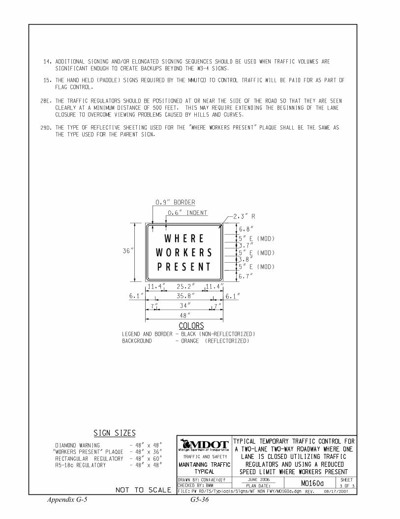
6.8"
3.7"
3.8"
6.1"
6.7"
W H E R E
P R E S E N T
W O R K E R S
7" 7"
5" E (MOD)
36" 5" E (MOD)
5" E (MOD)
11.4" 25.2" 11.4"
35.8"6.1"
34"
48"
COLORS
2.3" R
0.9" BORDER
0.6" INDENT
LEGEND AND BORDER - BLACK (NON-REFLECTORIZED)
BACKGROUND - ORANGE (REFLECTORIZED)
TYPICAL TEMPORARY TRAFFIC CONTROL FOR
A TWO-LANE TWO-WAY ROADWAY WHERE ONE
LANE IS CLOSED UTILIZING TRAFFIC
REGULATORS AND USING A REDUCED
SPEED LIMIT WHERE WORKERS PRESENT
CON:AE:djf
BMM
JUNE 2006
M0160a 3 3
THE TYPE OF REFLECTIVE SHEETING USED FOR THE "WHERE WORKERS PRESENT" PLAQUE SHALL BE THE SAME AS
THE TYPE USED FOR THE PARENT SIGN.
29D.
PW RD/TS/Typicals/Signs/MT NON FWY/M0160a.dgn
DIAMOND WARNING - 48" x 48"
"WORKERS PRESENT" PLAQUE - 48" x 36"
RECTANGULAR REGULATORY - 48" x 60"
R5-18c REGULATORY - 48" x 48"
14. ADDITIONAL SIGNING AND/OR ELONGATED SIGNING SEQUENCES SHOULD BE USED WHEN TRAFFIC VOLUMES ARE
SIGNIFICANT ENOUGH TO CREATE BACKUPS BEYOND THE W3-4 SIGNS.
08/17/2007
MAINTAINING TRAFFIC
TYPICAL
SHEET
Michigan Department of Transportation
FILE:
OF
TRAFFIC AND SAFETY
PLAN DATE:
DRAWN BY:
CHECKED BY:
REV. NOT TO SCALE
Appendix G-5 G5-36

Notes for Figure 6H-8—Typical Application 8 (MI)Road Closure with Off-Site Detour
Guidance:1. Regulatory traffic control devices should be modified as needed for the duration of the detour.
Option:2. If the road is closed a short distance beyond the intersection and there are few origin/destination points
beyond the intersection, the ROAD CLOSED and DETOUR signs on Type III Barricades may be locatedin the center of the traveled way.
3. A Route Sign Directional assembly may be placed on the far left corner of the intersection to augment or replace the one shown on the near right corner.
4. Flashing warning lights and/or flags may be used to call attention to the advance warning signs.5. Cardinal direction plaques may be used with route signs.
Page 6H-20 (MI) 2003 Edition
G5-37 Appendix G-5
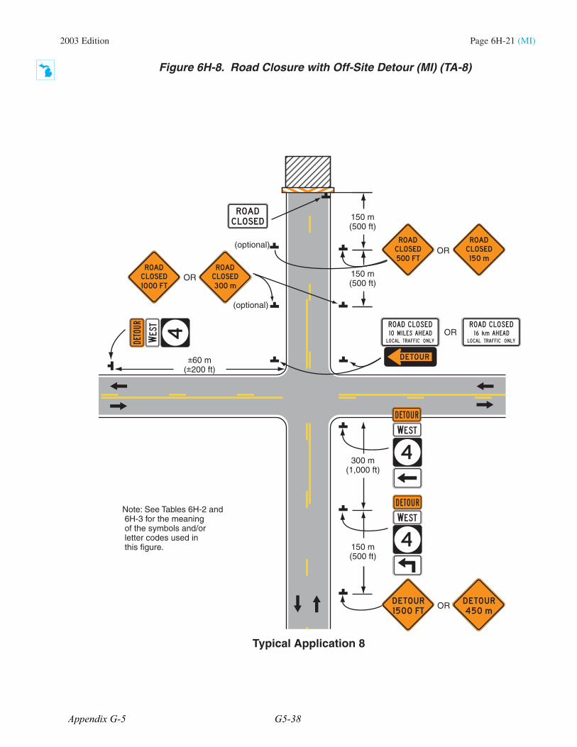
2003 Edition Page 6H-21 (MI)
Note: See Tables 6H-2 and 6H-3 for the meaning of the symbols and/or letter codes used in this figure.
Typical Application 8
OR
150 m(500 ft)
300 m(1,000 ft)
OR
150 m(500 ft)
150 m(500 ft)
OR
60 m( 200 ft)
OR
(optional)
(optional)
Figure 6H-8. Road Closure with Off-Site Detour (MI) (TA-8)
Appendix G-5 G5-38