appendix a category tables – release 5
TRANSCRIPT
Appendix A
Category Table Release 5.8 A-1
Appendix A Category Tables – Release 5.8
The Category Tables listed below are part of the TL 9000 standard. This is Release 5.8 of Appendix A of the Measurements Handbook. It may be used effective January 2022 for submitting TL 9000 data and must be used for June 2022 data forward until superseded by the next revision. Each revision is an approved release by TIA QuEST Forum and is identified by a release number. The latest release of these tables and their effective dates are available via the TL 9000 website and shall be used in conjunction with registrations per the rules noted in Section 4.1.1 of the Measurements Handbook. Organizations shall classify their products and report measurements according to the product categories listed in Table A-1. The Measurement Applicability Table (Normalization Units), Table A-2, lists specific measurements that apply to each category as well as the Normalization Units and other information necessary for compiling measurement reports.
a) List of Tables Table A-1 Category Definitions Table A-2 Measurement Applicability Table (Normalization Units) Table A-3 Network Element Impact Outage for SONE Table A-4 Transmission Standard Designations and Conversions Table A-5 Optical and Electrical Equivalency Table A-6 Measurements Summary Listing Table A-7 TL 9000 Data Submission Labels
b) Rules for Classification of Products or Services Please see the "Category Selection and Validation Guidelines" available on the tl9000.org web site for more information on how to determine the correct category for your product.
1) The definitions of categories in Table A-1 shall be used by organizations in categorizing their products.
2) An organization shall not classify a product or service in multiple categories. Therefore, any product or service from an organization must be classified in exactly one product or service category.
3) All new category selections must be approved by TIA QuEST Forum before the category can be added to the organization’s TL 9000 Certification public profile.
4) General-purpose products, such as computers, shall be classified by specific function, e.g., signaling, when provided as a system designed for that function. Otherwise, they shall be classified in a separate category, for example, Common Systems-Computers, designed for the general-purpose product.
5) A product shall be classified according to its primary function. For example, a digital transmission facility product with performance monitoring will be classified as a transmission product instead of an operations and maintenance product.

Appendix A
Category Table Release 5.8 A-2
6) The standard for classification is the product category, not the possible uses for the product. For example, if a product classification falls in the Outside Plant category, all products that are consistent with that category will be classified as such, even if the exact same product is sometimes used in the customer premises and even if a particular organization’s product is sold primarily into the customer premises market.
7) Organizations choosing a category in Families 1 through 6 or Family 8 cannot exclude Clause 8.3 in the Requirements Handbook in its entirety. Organizations without responsibility for design and development should look to the service categories in Family 7 for the appropriate category.
Category Splits: When a new edition of the Category Tables splits an existing category into two or more new categories, all the new categories are automatically added the TL 9000 Certification of any organization certified in the existing category. The organization does not have to have the new categories approved by TIA QuEST Forum or by its Certification Body. The organization does have to start to submit data in the new category or categories prior to the end of the implementation period for the new edition. It must also delete from its profile any of the new categories that do not apply once it starts submitting data in the new categories. Should there ever be the need to resubmit data, the resubmission should be made in the same category as the original submission. Category Combinations:
When a new edition of the Category Tables combines an existing category with an existing category, that category will be automatically added the TL 9000 Certification of any organization certified in the existing category. The organization does not have to have the new category approved by TIA QuEST Forum or by its Certification Body. The organization does have to start to submit data in the new category prior to the end of the implementation period for the new edition. It must also delete from its profile the previous category. Should there ever be the need to resubmit data, the resubmission should be made in the same category as the original submission.
c) Principles for Construction of the Category Table
1) Categories shall be defined so that they can be clearly assigned within a hierarchy of classification.
2) There are well-established rules for classification. 3) Categories should not be separated artificially if they can be logically
aggregated. 4) Categories should have clear definitions, which lend themselves to
unambiguous interpretation. 5) For each category, the level to which measurements may be aggregated
shall be defined. 6) Each category specification shall consist of standard elements. 7) The placement of the product or service in the hierarchy will reflect the
dominant use of the product or service. 8) Terminology used shall reflect standard technical meanings; wherever
possible aligned to relevant standards such as ITU-T, ETSI, ANSI, etc.
Appendix A
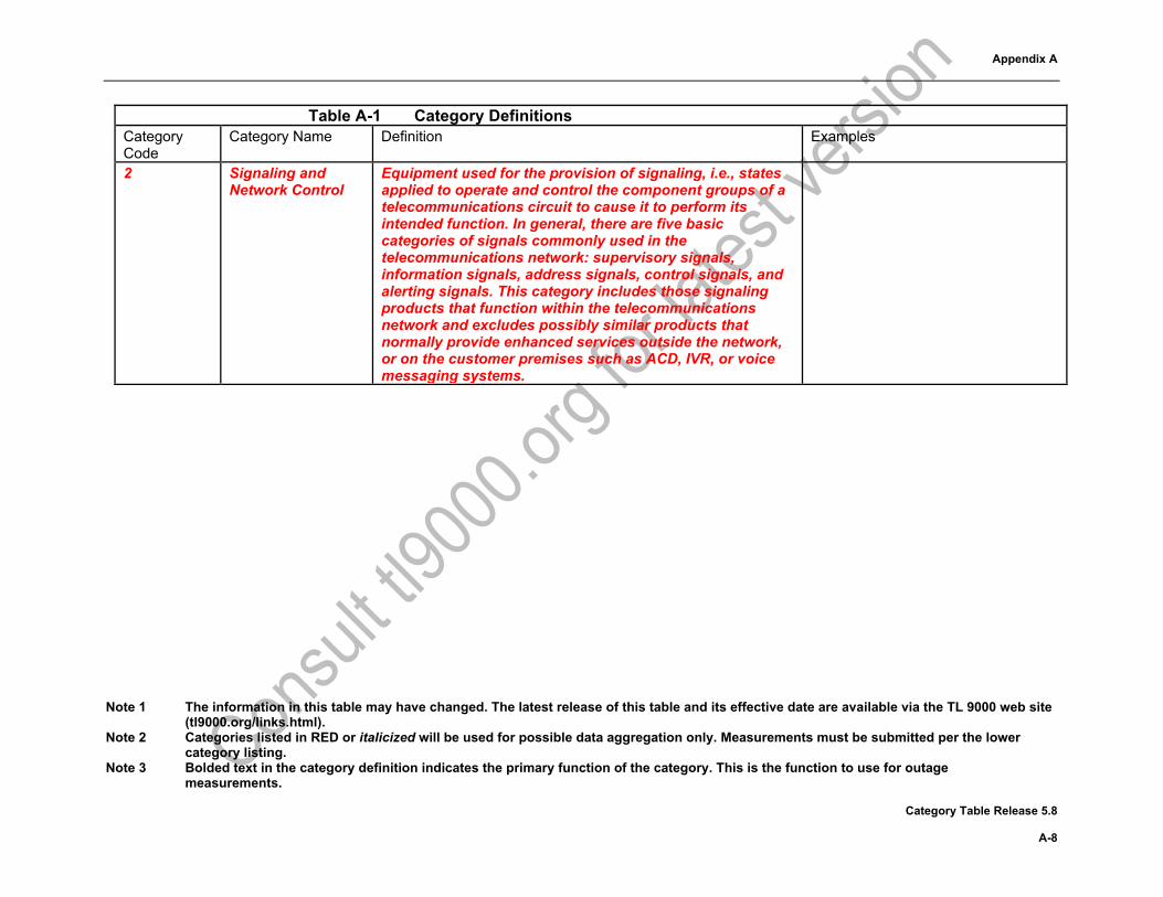
Note 1 The information in this table may have changed. The latest release of this table and its effective date are available via the TL 9000 web site (tl9000.org/links.html).
Note 2 Categories listed in RED or italicized will be used for possible data aggregation only. Measurements must be submitted per the lower category listing.
Note 3 Bolded text in the category definition indicates the primary function of the category. This is the function to use for outage measurements.
Category Table Release 5.8 A-3
Table A-1 Category Definitions
Table A-1 Category Definitions Category Code
Category Name Definition Examples
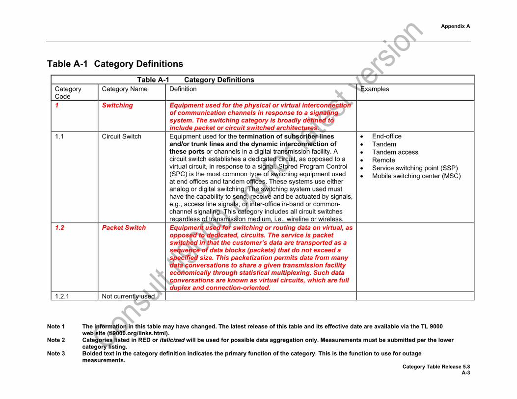
1 Switching Equipment used for the physical or virtual interconnection of communication channels in response to a signaling system. The switching category is broadly defined to include packet or circuit switched architectures.
1.1 Circuit Switch Equipment used for the termination of subscriber lines and/or trunk lines and the dynamic interconnection of these ports or channels in a digital transmission facility. A circuit switch establishes a dedicated circuit, as opposed to a virtual circuit, in response to a signal. Stored Program Control (SPC) is the most common type of switching equipment used at end offices and tandem offices. These systems use either analog or digital switching. The switching system used must have the capability to send, receive and be actuated by signals, e.g., access line signals, or inter-office in-band or common-channel signaling. This category includes all circuit switches regardless of transmission medium, i.e., wireline or wireless.
• End-office • Tandem • Tandem access • Remote • Service switching point (SSP) • Mobile switching center (MSC)
1.2 Packet Switch Equipment used for switching or routing data on virtual, as opposed to dedicated, circuits. The service is packet switched in that the customer’s data are transported as a sequence of data blocks (packets) that do not exceed a specified size. This packetization permits data from many data conversations to share a given transmission facility economically through statistical multiplexing. Such data conversations are known as virtual circuits, which are full duplex and connection-oriented.
1.2.1 Not currently used
Appendix A
Note 1 The information in this table may have changed. The latest release of this table and its effective date are available via the TL 9000 web site (tl9000.org/links.html).
Note 2 Categories listed in RED or italicized will be used for possible data aggregation only. Measurements must be submitted per the lower category listing.
Note 3 Bolded text in the category definition indicates the primary function of the category. This is the function to use for outage measurements.
Category Table Release 5.8 A-4
Table A-1 Category Definitions Category Code
Category Name Definition Examples
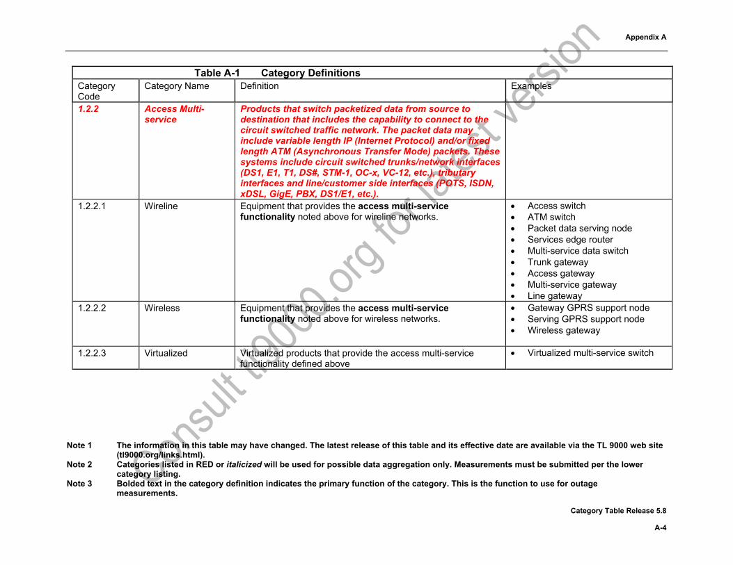
1.2.2 Access Multi-service
Products that switch packetized data from source to destination that includes the capability to connect to the circuit switched traffic network. The packet data may include variable length IP (Internet Protocol) and/or fixed length ATM (Asynchronous Transfer Mode) packets. These systems include circuit switched trunks/network interfaces (DS1, E1, T1, DS#, STM-1, OC-x, VC-12, etc.), tributary interfaces and line/customer side interfaces (POTS, ISDN, xDSL, GigE, PBX, DS1/E1, etc.).
1.2.2.1 Wireline Equipment that provides the access multi-service functionality noted above for wireline networks.
• Access switch • ATM switch • Packet data serving node • Services edge router • Multi-service data switch • Trunk gateway • Access gateway • Multi-service gateway • Line gateway
1.2.2.2 Wireless Equipment that provides the access multi-service functionality noted above for wireless networks.
• Gateway GPRS support node • Serving GPRS support node • Wireless gateway
1.2.2.3 Virtualized Virtualized products that provide the access multi-service
functionality defined above • Virtualized multi-service switch

Appendix A
Note 1 The information in this table may have changed. The latest release of this table and its effective date are available via the TL 9000 web site (tl9000.org/links.html).
Note 2 Categories listed in RED or italicized will be used for possible data aggregation only. Measurements must be submitted per the lower category listing.
Note 3 Bolded text in the category definition indicates the primary function of the category. This is the function to use for outage measurements.
Category Table Release 5.8 A-5
Table A-1 Category Definitions Category Code
Category Name Definition Examples
1.2.3 Media Gateways Products that provide an interface between different network transport protocols. The primary function of these products is to enable multimedia communications across networks such as PSTN, IP, ATM, 2G, 2.5G, 3G, 4G, 5G, or PBX. Media steaming functions such as echo cancellation, DTMF, and tone sender may also be located in the gateway. This includes virtualized products providing this interface and functions.
• Media Gateway • Virtualized media gateway
1.2.4 Core and Access Ethernet Switches
Equipment that provides data connections between servers and end hosts in data centers or campuses and are designed to switch layer 2 packets. The access switches typically connect end hosts in Campus networks or Servers in a Data center networks. The Core switches aggregate all the access switches and also connect to other switches in remote data centers. This category includes Enterprise Core and Access switches.
1.2.4.1 Legacy Ethernet Switches
Equipment that provides data connections between servers and end hosts in data centers or campuses consisting of proprietary hardware and software.
• Ethernet switch • Campus access switch • Top of rack switch • Data Center aggregation switch • Data Center core switch • Enterprise distribution switch
1.2.4.2 Virtualized Ethernet Switches
Software that provides data connections between servers and end hosts in data centers or campuses. This software providing the virtualized functions of an Ethernet switch runs on generic or customer specified hardware.
• NFV campus access switch • NFV Ethernet switch
1.2.5 Not currently used 1.2.6 Not currently used

Appendix A
Note 1 The information in this table may have changed. The latest release of this table and its effective date are available via the TL 9000 web site (tl9000.org/links.html).
Note 2 Categories listed in RED or italicized will be used for possible data aggregation only. Measurements must be submitted per the lower category listing.
Note 3 Bolded text in the category definition indicates the primary function of the category. This is the function to use for outage measurements.
Category Table Release 5.8 A-6
Table A-1 Category Definitions Category Code
Category Name Definition Examples
1.2.7 Application Servers Products that provide multimedia services. This includes virtualized products providing this interface and functions.
• Video over IP • Instant messaging • Voice features • Multi-media communications
server • Virtualized application server
1.2.8 Service and Network Controller (SNC)
Equipment that combines a Call Connection Agent (CCA) and possibly a signaling gateway (SG) and/or a service agent into one system. The CCA provides the necessary call processing functionality to support voice traffic on the core packet network including call control commands and communication with billing systems. A service agent supports supplementary services and generates TCAP messages to interact with Service Control Points for intelligent network services such as 800 and Local Number Portability. (NOTE: If the signaling gateway is not integrated with the CCA, the product belongs in product category 2.2 Signaling Controllers.)
• Service and network controller (SNC)
• Soft switch • Nextgen switch
1.2.9 Routers Equipment that routes packet data from source to destination. This may include variable length IP and/or fixed length ATM packets. This equipment is connected to multiple physical packet networks and routes or delivers packets between the networks. Routing generally uses software algorithms to optimize one or a combination of data-transport “measurements” such as delay, the use of reliable paths, “hops” between servers, etc. Routers do not include termination of PSTN traffic, however products whose primary function is routing but also support the capability to do protocol conversion and pass through of PSTN traffic (such as Pseudowire of E1/T1 signals) also are included in this product family.
Appendix A
Note 1 The information in this table may have changed. The latest release of this table and its effective date are available via the TL 9000 web site (tl9000.org/links.html).
Note 2 Categories listed in RED or italicized will be used for possible data aggregation only. Measurements must be submitted per the lower category listing.
Note 3 Bolded text in the category definition indicates the primary function of the category. This is the function to use for outage measurements.
Category Table Release 5.8 A-7
Table A-1 Category Definitions Category Code
Category Name Definition Examples
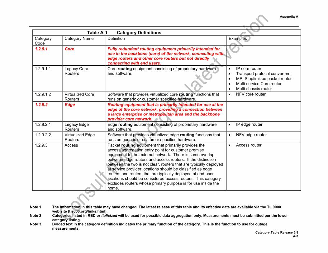
1.2.9.1 Core Fully redundant routing equipment primarily intended for use in the backbone (core) of the network, connecting with edge routers and other core routers but not directly connecting with end users.
1.2.9.1.1 Legacy Core Routers
Core routing equipment consisting of proprietary hardware and software.
• IP core router • Transport protocol converters • MPLS optimized packet router • Multi-service Core router • Multi-chassis router
1.2.9.1.2 Virtualized Core Routers
Software that provides virtualized core routing functions that runs on generic or customer specified hardware.
• NFV core router
1.2.9.2 Edge Routing equipment that is primarily intended for use at the edge of the core network, providing a connection between a large enterprise or metropolitan area and the backbone provider core network.
1.2.9.2.1 Legacy Edge Routers
Edge routing equipment consisting of proprietary hardware and software.
• IP edge router
1.2.9.2.2 Virtualized Edge Routers
Software that provides virtualized edge routing functions that runs on generic or customer specified hardware.
• NFV edge router
1.2.9.3 Access Packet routing equipment that primarily provides the access/aggregation entry point for customer premise equipment to the external network. There is some overlap between edge routers and access routers. If the distinction between the two is not clear, routers that are typically deployed at service provider locations should be classified as edge routers and routers that are typically deployed at end-user locations should be considered access routers. This category excludes routers whose primary purpose is for use inside the home.
• Access router
Appendix A
Note 1 The information in this table may have changed. The latest release of this table and its effective date are available via the TL 9000 web site (tl9000.org/links.html).
Note 2 Categories listed in RED or italicized will be used for possible data aggregation only. Measurements must be submitted per the lower category listing.
Note 3 Bolded text in the category definition indicates the primary function of the category. This is the function to use for outage measurements.
Category Table Release 5.8 A-8
Table A-1 Category Definitions Category Code
Category Name Definition Examples
2 Signaling and Network Control
Equipment used for the provision of signaling, i.e., states applied to operate and control the component groups of a telecommunications circuit to cause it to perform its intended function. In general, there are five basic categories of signals commonly used in the telecommunications network: supervisory signals, information signals, address signals, control signals, and alerting signals. This category includes those signaling products that function within the telecommunications network and excludes possibly similar products that normally provide enhanced services outside the network, or on the customer premises such as ACD, IVR, or voice messaging systems.

Appendix A
Note 1 The information in this table may have changed. The latest release of this table and its effective date are available via the TL 9000 web site (tl9000.org/links.html).
Note 2 Categories listed in RED or italicized will be used for possible data aggregation only. Measurements must be submitted per the lower category listing.
Note 3 Bolded text in the category definition indicates the primary function of the category. This is the function to use for outage measurements.
Category Table Release 5.8 A-9
Table A-1 Category Definitions Category Code
Category Name Definition Examples
2.1 Service Control {formerly Service Control Point (SCP)}
A hardware and software system or a fully software based system (virtualized) that provides a signaling point that functions as a database to provide information to another service control network element or Service Switching Point (SSP). Transaction Capabilities Application Part (TCAP) queries and responses are used to communicate with the network element as is done for 800 Data Base Service and Alternate Billing Service (ABS). These may support one or more services per network element and they may be deployed singularly as stand-alone nodes, as mated pairs, or as multiple replicates (more than 2) to increase their availability. They are associated with applications that consist of service-specific software and a database of customer-related information. This product category includes conventional Service Control Point (SCP) equipment, plus other platforms such as service nodes, intelligent peripherals, or service resource facilities, which may combine capabilities of a SCP, SSP or that may be used to provide Advanced Intelligent Network (AIN) functionality or other enhanced services within the network. It also includes Source Based Routing (SBR) which consists of a Routing Database (RDB); a logical routing directory component that an originating Call Server accesses to convert external routing information, such as a dialed telephone number, into internal destination IP routing information. The Routing Database may be based around DNS and ENUM technology; the ENUM server may be used to provide a translation from dialed digits to corresponding SIP URI, from which the Call Server may provide the IP address which is used by call control to send a SIP message to a subsequent call server, which may or may not be an entity in the same network domain.
• Service control point • Service node • Service resource facilities • Source based router • Virtualized service node
Appendix A
Note 1 The information in this table may have changed. The latest release of this table and its effective date are available via the TL 9000 web site (tl9000.org/links.html).
Note 2 Categories listed in RED or italicized will be used for possible data aggregation only. Measurements must be submitted per the lower category listing.
Note 3 Bolded text in the category definition indicates the primary function of the category. This is the function to use for outage measurements.
Category Table Release 5.8 A-10
Table A-1 Category Definitions Category Code
Category Name Definition Examples
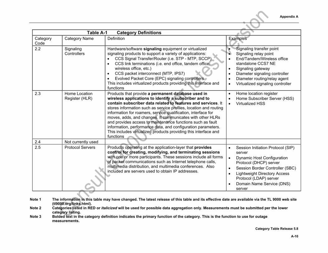
2.2 Signaling Controllers
Hardware/software signaling equipment or virtualized signaling products to support a variety of applications: • CCS Signal Transfer/Router (i.e. STP - MTP, SCCP) • CCS link terminations (i.e. end office, tandem office,
wireless office, etc.) • CCS packet interconnect (MTP, IPS7) • Evolved Packet Core (EPC) signaling controllers This includes virtualized products providing this interface and functions
• Signaling transfer point • Signaling relay point • End/Tandem/Wireless office
standalone CCS7 NE • Signaling gateway • Diameter signaling controller • Diameter routing/relay agent • Virtualized signaling controller
2.3 Home Location Register (HLR)
Products that provide a permanent database used in wireless applications to identify a subscriber and to contain subscriber data related to features and services. It stores information such as service profiles, location and routing information for roamers, service qualification, interface for moves, adds, and changes. It communicates with other HLRs and provides access to maintenance functions such as fault information, performance data, and configuration parameters. This includes virtualized products providing this interface and functions
• Home location register • Home Subscriber Server (HSS) • Virtualized HSS
2.4 Not currently used 2.5 Protocol Servers Products operating at the application-layer that provides
control for creating, modifying, and terminating sessions with one or more participants. These sessions include all forms of packet communications such as Internet telephone calls, multimedia distribution, and multimedia conferences. Also included are servers used to obtain IP addresses.
• Session Initiation Protocol (SIP) server
• Dynamic Host Configuration Protocol (DHCP) server
• Session Border Controller (SBC) • Lightweight Directory Access
Protocol (LDAP) server • Domain Name Service (DNS)
server
Appendix A
Note 1 The information in this table may have changed. The latest release of this table and its effective date are available via the TL 9000 web site (tl9000.org/links.html).
Note 2 Categories listed in RED or italicized will be used for possible data aggregation only. Measurements must be submitted per the lower category listing.
Note 3 Bolded text in the category definition indicates the primary function of the category. This is the function to use for outage measurements.
Category Table Release 5.8 A-11
Table A-1 Category Definitions Category Code
Category Name Definition Examples
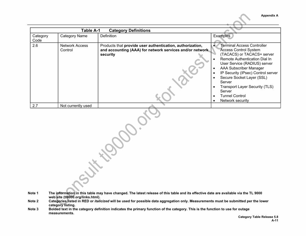
2.6 Network Access Control
Products that provide user authentication, authorization, and accounting (AAA) for network services and/or network security
• Terminal Access Controller Access Control System (TACACS) or TACACS+ server
• Remote Authentication Dial In User Service (RADIUS) server
• AAA Subscriber Manager • IP Security (IPsec) Control server • Secure Socket Layer (SSL)
Server • Transport Layer Security (TLS)
Server • Tunnel Control • Network security
2.7 Not currently used

Appendix A
Note 1 The information in this table may have changed. The latest release of this table and its effective date are available via the TL 9000 web site (tl9000.org/links.html).
Note 2 Categories listed in RED or italicized will be used for possible data aggregation only. Measurements must be submitted per the lower category listing.
Note 3 Bolded text in the category definition indicates the primary function of the category. This is the function to use for outage measurements.
Category Table Release 5.8 A-12
Table A-1 Category Definitions Category Code
Category Name Definition Examples
2.8 Mobility Management Entity (MME)
Products within the LTE Evolved Packet Core (EPC) that provides the signaling and control functions needed to manage the User Equipment (UE) access to network connections, the assignment of network resources, and the management of the mobility states to support tracking, paging, roaming and handovers. MME controls all control plane functions related to subscriber and session management. MME manages the eNodeB elements. The MME is the key element for gateway selection within the EPC (Serving and PDN). It also performs signaling and selection of legacy gateways for handovers to 2G/3G networks. The MME also performs the bearer management control functions to establish the bearer paths that the UE/ATs use. The MME supports end-user authentication as well as initiation and negotiation of ciphering and integrity protection algorithms, the signaling procedures used to set up packet data context and negotiate associated parameters like QoS, and idle terminal location management: Equipment which combines SGSN functionality with the MME shall be included in this product category. This includes virtualized products providing this interface and functions
• Mobility Management Entity (MME)
• Combined Serving GPRS Support Node (SGSN)/MME
• Virtualized MME
3 Transmission Systems
Equipment used for the connection of the switched and interoffice networks with individual customers. An integral part of the distribution network is the loop that connects the customer to the local central office (CO), thus providing access to the interoffice network.
Appendix A
Note 1 The information in this table may have changed. The latest release of this table and its effective date are available via the TL 9000 web site (tl9000.org/links.html).
Note 2 Categories listed in RED or italicized will be used for possible data aggregation only. Measurements must be submitted per the lower category listing.
Note 3 Bolded text in the category definition indicates the primary function of the category. This is the function to use for outage measurements.
Category Table Release 5.8 A-13
Table A-1 Category Definitions Category Code
Category Name Definition Examples
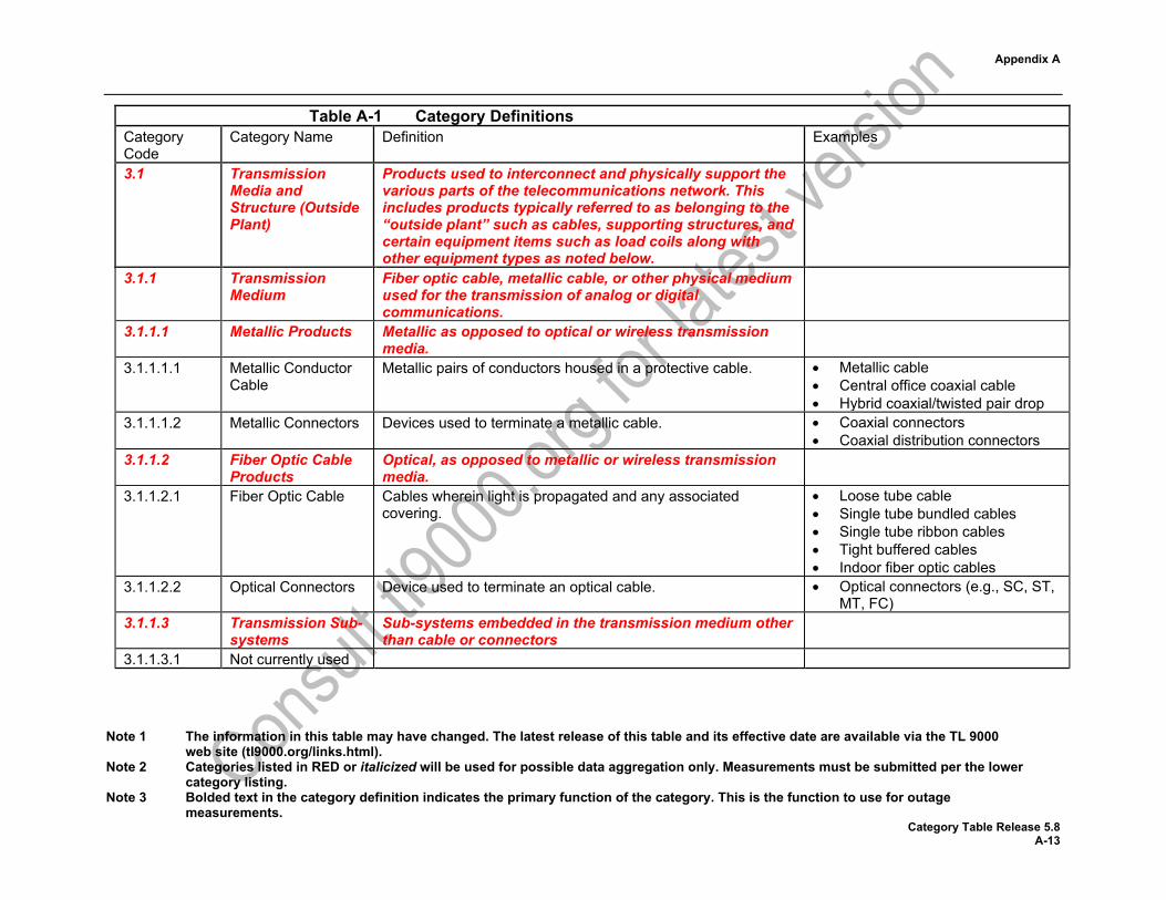
3.1 Transmission Media and Structure (Outside Plant)
Products used to interconnect and physically support the various parts of the telecommunications network. This includes products typically referred to as belonging to the “outside plant” such as cables, supporting structures, and certain equipment items such as load coils along with other equipment types as noted below.
3.1.1 Transmission Medium
Fiber optic cable, metallic cable, or other physical medium used for the transmission of analog or digital communications.
3.1.1.1 Metallic Products Metallic as opposed to optical or wireless transmission media.
3.1.1.1.1 Metallic Conductor Cable
Metallic pairs of conductors housed in a protective cable. • Metallic cable • Central office coaxial cable • Hybrid coaxial/twisted pair drop
3.1.1.1.2 Metallic Connectors Devices used to terminate a metallic cable. • Coaxial connectors • Coaxial distribution connectors
3.1.1.2 Fiber Optic Cable Products
Optical, as opposed to metallic or wireless transmission media.
3.1.1.2.1 Fiber Optic Cable Cables wherein light is propagated and any associated covering.
• Loose tube cable • Single tube bundled cables • Single tube ribbon cables • Tight buffered cables • Indoor fiber optic cables
3.1.1.2.2 Optical Connectors Device used to terminate an optical cable. • Optical connectors (e.g., SC, ST, MT, FC)
3.1.1.3 Transmission Sub-systems
Sub-systems embedded in the transmission medium other than cable or connectors
3.1.1.3.1 Not currently used

Appendix A
Note 1 The information in this table may have changed. The latest release of this table and its effective date are available via the TL 9000 web site (tl9000.org/links.html).
Note 2 Categories listed in RED or italicized will be used for possible data aggregation only. Measurements must be submitted per the lower category listing.
Note 3 Bolded text in the category definition indicates the primary function of the category. This is the function to use for outage measurements.
Category Table Release 5.8 A-14
Table A-1 Category Definitions Category Code
Category Name Definition Examples
3.1.1.3.2 Passive Optical Sub-systems
Optical sub-systems containing no electronics. This includes passive optical modules containing two or more individual passive optical sub-systems or systems.
• Optical passive wavelength division multiplexer (PWDM)
• Optical add drop multiplexers • Combined optical
couplers/splitters/filters 3.1.1.3.3 Other Sub-systems Other transmission sub-systems not specifically covered in
other transmission component categories. • Surge protectors • Bonding and grounding hardware
or ground wire • Taps • Electronic line filters • Coaxial drop amplifiers • Fiber optic data links
3.1.1.3.4 Fixed Antenna Systems
Systems used for the transmission and receipt of telecommunication signals through the air. This includes radio, satellite, and optical antenna systems.
• Microwave antenna system • Fixed wireless antenna system • Satellite antenna system • Optical antenna system
3.1.2 Physical Structure Physical structures used for the support of telephone transmission media.
3.1.2.1 Enclosures Enclosures used for network equipment located in the outside plant.
• Fiber optic splice enclosures • Optical network unit (ONU)
enclosures • Organizer assemblies • Seal assemblies • Controlled environment vaults • Pedestals
3.1.2.2 Support Structures Products used for the physical support of transmission media or enclosures and associated items.
• Telephone poles • Microwave/radio towers
Appendix A
Note 1 The information in this table may have changed. The latest release of this table and its effective date are available via the TL 9000 web site (tl9000.org/links.html).
Note 2 Categories listed in RED or italicized will be used for possible data aggregation only. Measurements must be submitted per the lower category listing.
Note 3 Bolded text in the category definition indicates the primary function of the category. This is the function to use for outage measurements.
Category Table Release 5.8 A-15
Table A-1 Category Definitions Category Code
Category Name Definition Examples
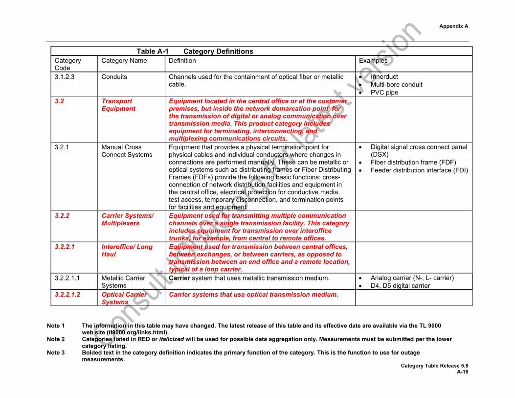
3.1.2.3 Conduits Channels used for the containment of optical fiber or metallic cable.
• Innerduct • Multi-bore conduit • PVC pipe
3.2 Transport Equipment
Equipment located in the central office or at the customer premises, but inside the network demarcation point, for the transmission of digital or analog communication over transmission media. This product category includes equipment for terminating, interconnecting, and multiplexing communications circuits.
3.2.1 Manual Cross Connect Systems
Equipment that provides a physical termination point for physical cables and individual conductors where changes in connections are performed manually. These can be metallic or optical systems such as distributing frames or Fiber Distributing Frames (FDFs) provide the following basic functions: cross-connection of network distribution facilities and equipment in the central office, electrical protection for conductive media, test access, temporary disconnection, and termination points for facilities and equipment.
• Digital signal cross connect panel (DSX)
• Fiber distribution frame (FDF) • Feeder distribution interface (FDI)
3.2.2 Carrier Systems/ Multiplexers
Equipment used for transmitting multiple communication channels over a single transmission facility. This category includes equipment for transmission over interoffice trunks, for example, from central to remote offices.
3.2.2.1 Interoffice/ Long Haul
Equipment used for transmission between central offices, between exchanges, or between carriers, as opposed to transmission between an end office and a remote location, typical of a loop carrier.
3.2.2.1.1 Metallic Carrier Systems
Carrier system that uses metallic transmission medium. • Analog carrier (N-, L- carrier) • D4, D5 digital carrier
3.2.2.1.2 Optical Carrier Systems
Carrier systems that use optical transmission medium.

Appendix A
Note 1 The information in this table may have changed. The latest release of this table and its effective date are available via the TL 9000 web site (tl9000.org/links.html).
Note 2 Categories listed in RED or italicized will be used for possible data aggregation only. Measurements must be submitted per the lower category listing.
Note 3 Bolded text in the category definition indicates the primary function of the category. This is the function to use for outage measurements.
Category Table Release 5.8 A-16
Table A-1 Category Definitions Category Code
Category Name Definition Examples
3.2.2.1.2.1 Optical Transport Systems
Fully featured digital transmission system using optical medium without WDM or switching at the optical layer other than receiver or transmitter protection switching
• OC-3, 12, 48, or 192 SONET equipment configurable as linear or ring
• Similar for STM-x SDH equipment
• IP optical transport • Optical Transport Networking
3.2.2.1.2.2 WDM/DWDM/ Optical Amplification
Shelf level systems used for multiplexing, de-multiplexing, or amplification of optical signals. Lack the built in protection, electrical conversion and other features of a SONET Transport System.
• Wavelength division multiplexer (WDM)
• Dense wavelength division multiplexer (DWDM)
3.2.2.1.2.3 Reconfigurable Optical Add-Drop Multiplexer (ROADM)
An add-drop multiplexer with the ability to network wavelengths in a granular, automated fashion in metro and regional networks, with integrated transport and switching at both the wavelength and the transport (such as SONET/SDH or IP) layers in a single network element. NOTE: SONET/SDH products which have added WDM capabilities or WDM products that have added SONET/SDH capabilities are to be classified in this product category
• Reconfigurable Optical Add-Drop Multiplexer (ROADM)
• Optical add-drop switches • Wavelength Switching Systems
(WSS) • Optical Transport Network (OTN)
elements
3.2.2.1.3 Microwave Carrier system that employs fixed microwave transmission. • 6, 8, 11, 18, or 40 gigahertz microwave radio
• 2.4 or 5.8 gigahertz license free radio
Appendix A
Note 1 The information in this table may have changed. The latest release of this table and its effective date are available via the TL 9000 web site (tl9000.org/links.html).
Note 2 Categories listed in RED or italicized will be used for possible data aggregation only. Measurements must be submitted per the lower category listing.
Note 3 Bolded text in the category definition indicates the primary function of the category. This is the function to use for outage measurements.
Category Table Release 5.8 A-17
Table A-1 Category Definitions Category Code
Category Name Definition Examples
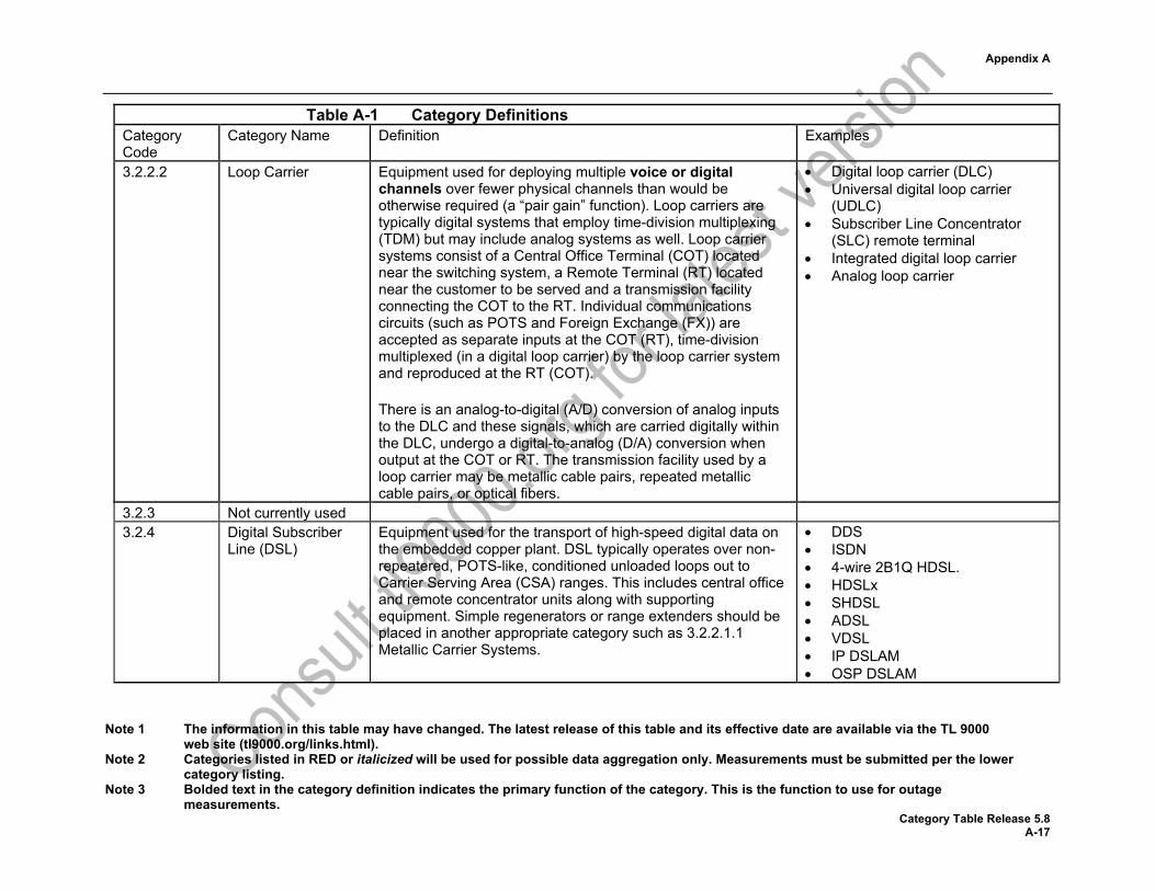
3.2.2.2 Loop Carrier Equipment used for deploying multiple voice or digital channels over fewer physical channels than would be otherwise required (a “pair gain” function). Loop carriers are typically digital systems that employ time-division multiplexing (TDM) but may include analog systems as well. Loop carrier systems consist of a Central Office Terminal (COT) located near the switching system, a Remote Terminal (RT) located near the customer to be served and a transmission facility connecting the COT to the RT. Individual communications circuits (such as POTS and Foreign Exchange (FX)) are accepted as separate inputs at the COT (RT), time-division multiplexed (in a digital loop carrier) by the loop carrier system and reproduced at the RT (COT). There is an analog-to-digital (A/D) conversion of analog inputs to the DLC and these signals, which are carried digitally within the DLC, undergo a digital-to-analog (D/A) conversion when output at the COT or RT. The transmission facility used by a loop carrier may be metallic cable pairs, repeated metallic cable pairs, or optical fibers.
• Digital loop carrier (DLC) • Universal digital loop carrier
(UDLC) • Subscriber Line Concentrator
(SLC) remote terminal • Integrated digital loop carrier • Analog loop carrier
3.2.3 Not currently used 3.2.4 Digital Subscriber
Line (DSL) Equipment used for the transport of high-speed digital data on the embedded copper plant. DSL typically operates over non-repeatered, POTS-like, conditioned unloaded loops out to Carrier Serving Area (CSA) ranges. This includes central office and remote concentrator units along with supporting equipment. Simple regenerators or range extenders should be placed in another appropriate category such as 3.2.2.1.1 Metallic Carrier Systems.
• DDS • ISDN • 4-wire 2B1Q HDSL. • HDSLx • SHDSL • ADSL • VDSL • IP DSLAM • OSP DSLAM

Appendix A
Note 1 The information in this table may have changed. The latest release of this table and its effective date are available via the TL 9000 web site (tl9000.org/links.html).
Note 2 Categories listed in RED or italicized will be used for possible data aggregation only. Measurements must be submitted per the lower category listing.
Note 3 Bolded text in the category definition indicates the primary function of the category. This is the function to use for outage measurements.
Category Table Release 5.8 A-18
Table A-1 Category Definitions Category Code
Category Name Definition Examples
3.2.5 Fiber to the User Equipment used for the bi-directional transport of telecommunications signals over optical fiber between the central office, remote digital loop carrier or other network node and the end user. This includes systems which may provide connections over copper in addition to the fiber connections.
• Fiber to the home (FTTH) • Fiber to the user (FTTU) • Passive optical networks (PON) • Fiber to the “x” (FTTx)
3.2.6 Video Transmission Equipment
Equipment used in the transmission and manipulation of video signals located at the head end, central office, or hub locations and not the customer premises.
• Analog CATV transmitters • Analog CATV repeaters • Analog CATV head end
equipment • Digital video multiplexer • Digital video transrater • Digital video router • Digital video ad splicer • Cable video server • Digital video modulator • QAM modulators • Ad splicers
3.3 Wireless Transmission
Equipment used for analog or digital transmission to the subscriber unique to wireless services. This category does not include interoffice or long-haul wireless carrier systems such as long-haul microwave transmission
3.3.1 Base Station Controller Equipment
Equipment that provides the interface between wireless systems and the network switching system. It provides, for example, electrical signaling isolation as well as switching, routing, billing, and features capabilities. It provides subsystems for vocoding and selecting hand off decision.
• BSC • BSS • Radio Network Controller (RNC)

Appendix A
Note 1 The information in this table may have changed. The latest release of this table and its effective date are available via the TL 9000 web site (tl9000.org/links.html).
Note 2 Categories listed in RED or italicized will be used for possible data aggregation only. Measurements must be submitted per the lower category listing.
Note 3 Bolded text in the category definition indicates the primary function of the category. This is the function to use for outage measurements.
Category Table Release 5.8 A-19
Table A-1 Category Definitions Category Code
Category Name Definition Examples
3.3.2 Base Transceiver System (BTS)
Equipment that provides the radio link to the mobile subscribers. It is connected to the BSC/RNC/MME (aggregation node) though a backhaul interface between the aggregation node and BTS for both vocoded and overhead packet traffic. This includes terminals and repeaters.
3.3.2.1 Basic Second generation (2G) and earlier equipment that provides the radio link to mobile subscribers.
• 2G BTS • 2G Wireless repeater • Analog BTS
3.3.2.2 Advanced Post second generation (2.5G) or third generation (3G) equipment that provides the radio link to mobile subscribers. This includes Radio Resource Control, Paging Control, Handoff/Handover Function, Context Function, Location Register, and Security Key Distribution in the control plane and, for the bearer plane, Backhaul Aggregation, QoS Policy Enforcement, IP Access Control, Data Path Function, and MIP Foreign Agent Capabilities. This includes systems with a distributed architecture for the BTS that has a digital baseband unit (BBU) separated from a remote radio unit (RRU).
• 3G BTS • 3G Wireless repeater • NodeB
3.3.2.3 4G Fourth generation (4G) equipment that provides the radio link to mobile and nomadic subscribers. This includes LTE and WiMAX BTS equipment. This includes systems with a distributed architecture for the BTS that has a digital baseband unit (BBU) separated from a remote radio unit (RRU).
• LTE BTS • WiMAX BTS • eNodeB

Appendix A
Note 1 The information in this table may have changed. The latest release of this table and its effective date are available via the TL 9000 web site (tl9000.org/links.html).
Note 2 Categories listed in RED or italicized will be used for possible data aggregation only. Measurements must be submitted per the lower category listing.
Note 3 Bolded text in the category definition indicates the primary function of the category. This is the function to use for outage measurements.
Category Table Release 5.8 A-20
Table A-1 Category Definitions Category Code
Category Name Definition Examples
3.3.2.4 Small Cell Radios Low-powered radio access nodes that operate in licensed and unlicensed spectrum that have a range of 10 meters to 200 meters as opposed to a standard macrocell BTS which might have a range of a few kilometers. Small cells include femtocells, picocells, and microcells. Small-cell networks can also be realized by means of distributed radio technology consisting of centralized baseband units and remote radio heads. This product category contains products designed primarily for use in commercial or large private wireless networks. Products designed for use on customer premises such as in homes or small businesses belong in product category 6.2.8 Home Base Station.
• Femtocell • Picocell • Microcell
3.3.2.5 Combined Equipment that provides the radio link to mobile subscribers. This equipment can operate as a 2.5G, 3G, 4G and/or 5G BTS. This includes systems with a distributed architecture for the BTS that has a digital baseband unit (BBU) separated from a remote radio unit (RRU).
• Combined BTS • Multi-technology BTS
3.3.2.6 5G Fifth generation (5G) equipment that provides the radio link to mobile, nomadic, and fixed subscribers. This includes systems with a distributed architecture for the BTS that has a digital baseband unit (BBU) separated from a remote radio unit (RRU)
• 5G BTS
3.3.3 Not currently used 3.3.4 WLAN Base Station
Equipment Equipment that provides the wireless data interface (such as IEEE 802.11 or IEEE 802.16) to wireless data network mobile subscribers.
• Wireless mesh point • Wireless data access point • Wireless mesh network access
point • Worldwide Interoperability for
Microwave Access (WiMAX)
Appendix A
Note 1 The information in this table may have changed. The latest release of this table and its effective date are available via the TL 9000 web site (tl9000.org/links.html).
Note 2 Categories listed in RED or italicized will be used for possible data aggregation only. Measurements must be submitted per the lower category listing.
Note 3 Bolded text in the category definition indicates the primary function of the category. This is the function to use for outage measurements.
Category Table Release 5.8 A-21
Table A-1 Category Definitions Category Code
Category Name Definition Examples
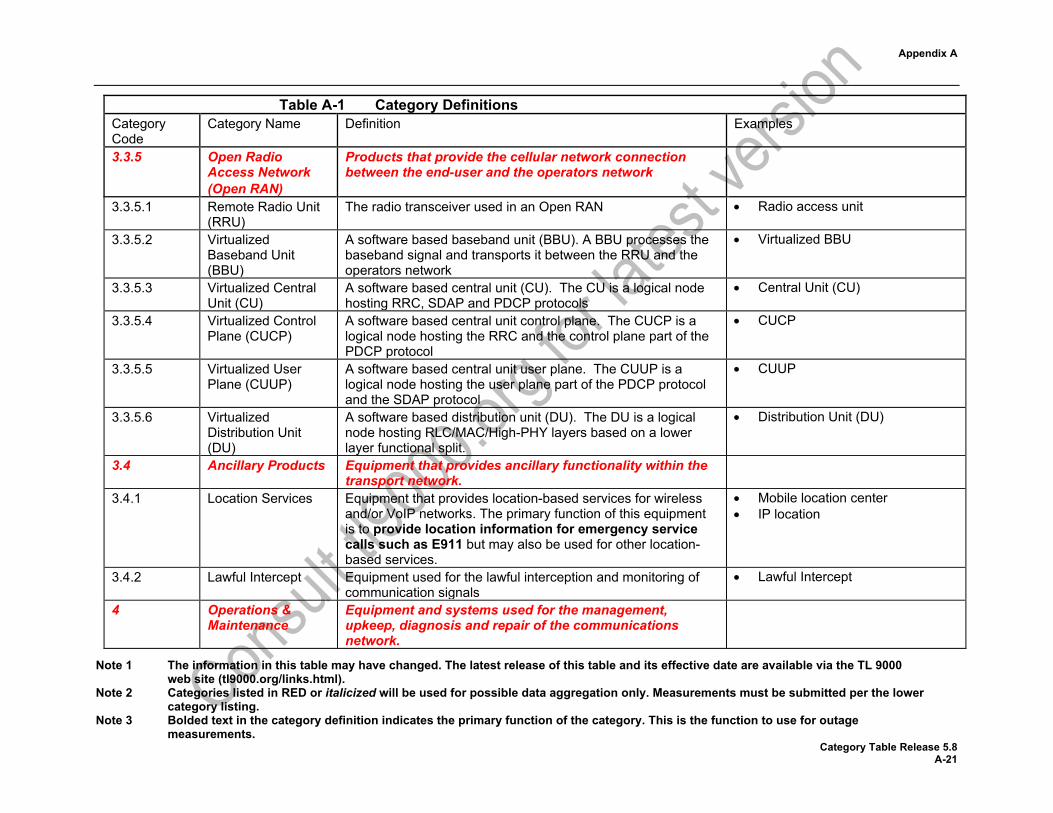
3.3.5 Open Radio Access Network (Open RAN)
Products that provide the cellular network connection between the end-user and the operators network
3.3.5.1 Remote Radio Unit (RRU)
The radio transceiver used in an Open RAN • Radio access unit
3.3.5.2 Virtualized Baseband Unit (BBU)
A software based baseband unit (BBU). A BBU processes the baseband signal and transports it between the RRU and the operators network
• Virtualized BBU
3.3.5.3 Virtualized Central Unit (CU)
A software based central unit (CU). The CU is a logical node hosting RRC, SDAP and PDCP protocols
• Central Unit (CU)
3.3.5.4 Virtualized Control Plane (CUCP)
A software based central unit control plane. The CUCP is a logical node hosting the RRC and the control plane part of the PDCP protocol
• CUCP
3.3.5.5 Virtualized User Plane (CUUP)
A software based central unit user plane. The CUUP is a logical node hosting the user plane part of the PDCP protocol and the SDAP protocol
• CUUP
3.3.5.6 Virtualized Distribution Unit (DU)
A software based distribution unit (DU). The DU is a logical node hosting RLC/MAC/High-PHY layers based on a lower layer functional split.
• Distribution Unit (DU)
3.4 Ancillary Products Equipment that provides ancillary functionality within the transport network.
3.4.1 Location Services Equipment that provides location-based services for wireless and/or VoIP networks. The primary function of this equipment is to provide location information for emergency service calls such as E911 but may also be used for other location-based services.
• Mobile location center • IP location
3.4.2 Lawful Intercept Equipment used for the lawful interception and monitoring of communication signals
• Lawful Intercept
4 Operations & Maintenance
Equipment and systems used for the management, upkeep, diagnosis and repair of the communications network.

Appendix A
Note 1 The information in this table may have changed. The latest release of this table and its effective date are available via the TL 9000 web site (tl9000.org/links.html).
Note 2 Categories listed in RED or italicized will be used for possible data aggregation only. Measurements must be submitted per the lower category listing.
Note 3 Bolded text in the category definition indicates the primary function of the category. This is the function to use for outage measurements.
Category Table Release 5.8 A-22
Table A-1 Category Definitions Category Code
Category Name Definition Examples
4.1 Test Systems Equipment used to support testing of the network. This category includes permanently installed equipment that provides a centralized test capability or local test access, as opposed to portable equipment, as might be carried by a craftsperson. Types of test systems are equipment that provides test access to transmission circuits, equipment to perform the tests or computer software used to communicate with the CO access and test equipment.
• In-line test equipment • Monitoring equipment • Parallel test equipment • Network test software
4.2 Operations Support Systems
Systems that provide TMN (Telecommunication Management Network) compliant, flexible, scalable, and interoperable solutions to automate service activation, service assurance, and network capacity management processes to existing and emerging network services and equipment providers at the network or element level
4.2.1 On-line Critical Real time network or element management systems, demanding high availability, typically 24 hours a day and 7 days per week.
4.2.1.1 Legacy On-line Critical
Network or element management systems for managing legacy networks.
• Network traffic management • Surveillance of 911 •
4.2.1.2 NFV Orchestrator Software that provides orchestration and management of end-to-end network services including integration with SDN controllers, OSS/BSS systems, and VNF managers.
• NFV Orchestrator • Software Defined Network (SDN)
Controller 4.2.2 On-line Non-
critical Real time network or element management systems with lower availability demands than on-line critical systems.
4.2.2.1 Legacy On-line Non-critical
Network or element management systems for managing legacy networks
• Provisioning • Dispatch • Maintenance • Configuration management
Appendix A
Note 1 The information in this table may have changed. The latest release of this table and its effective date are available via the TL 9000 web site (tl9000.org/links.html).
Note 2 Categories listed in RED or italicized will be used for possible data aggregation only. Measurements must be submitted per the lower category listing.
Note 3 Bolded text in the category definition indicates the primary function of the category. This is the function to use for outage measurements.
Category Table Release 5.8 A-23
Table A-1 Category Definitions Category Code
Category Name Definition Examples
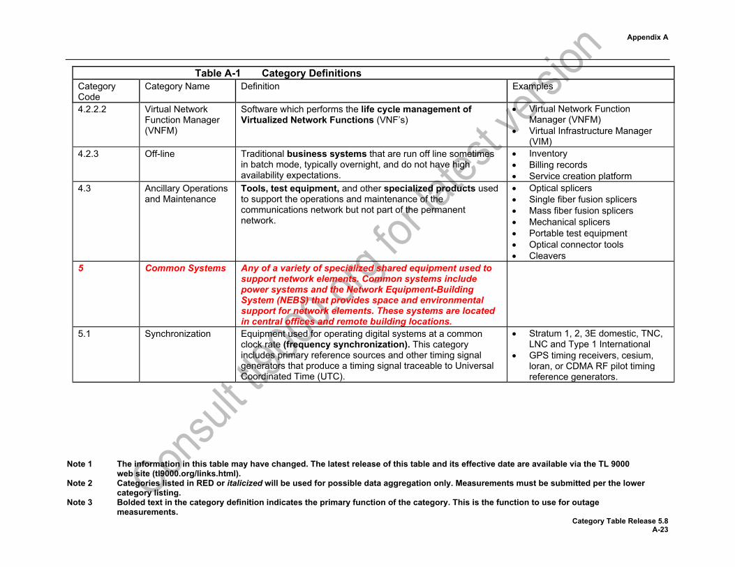
4.2.2.2 Virtual Network Function Manager (VNFM)
Software which performs the life cycle management of Virtualized Network Functions (VNF’s)
• Virtual Network Function Manager (VNFM)
• Virtual Infrastructure Manager (VIM)
4.2.3 Off-line Traditional business systems that are run off line sometimes in batch mode, typically overnight, and do not have high availability expectations.
• Inventory • Billing records • Service creation platform
4.3 Ancillary Operations and Maintenance
Tools, test equipment, and other specialized products used to support the operations and maintenance of the communications network but not part of the permanent network.
• Optical splicers • Single fiber fusion splicers • Mass fiber fusion splicers • Mechanical splicers • Portable test equipment • Optical connector tools • Cleavers
5 Common Systems Any of a variety of specialized shared equipment used to support network elements. Common systems include power systems and the Network Equipment-Building System (NEBS) that provides space and environmental support for network elements. These systems are located in central offices and remote building locations.
5.1 Synchronization Equipment used for operating digital systems at a common clock rate (frequency synchronization). This category includes primary reference sources and other timing signal generators that produce a timing signal traceable to Universal Coordinated Time (UTC).
• Stratum 1, 2, 3E domestic, TNC, LNC and Type 1 International
• GPS timing receivers, cesium, loran, or CDMA RF pilot timing reference generators.

Appendix A
Note 1 The information in this table may have changed. The latest release of this table and its effective date are available via the TL 9000 web site (tl9000.org/links.html).
Note 2 Categories listed in RED or italicized will be used for possible data aggregation only. Measurements must be submitted per the lower category listing.
Note 3 Bolded text in the category definition indicates the primary function of the category. This is the function to use for outage measurements.
Category Table Release 5.8 A-24
Table A-1 Category Definitions Category Code
Category Name Definition Examples
5.2 General Purpose Computers
A category reserved for computer complexes (one or more interconnected machines) that perform general business functions but that do not provide any telephony transmission or storage service to telecom customers, or that may provide such services, but are not sold to the customer as part of a system designed exclusively for that purpose. The purposes to which such machines may be put include but are not limited to: • Accounting systems • Billing systems • Legal systems • Ordering systems • Business Information systems • HR functions • Engineering and support functions • Marketing and Sales functions
• Terminals • PCs • Workstations • Mini, mid, mainframes
5.3 Power Systems Equipment used for the provision of power to network equipment. Power systems provide two principal functions: the conversion of the commercial AC power source to DC voltages required by the network equipment and the generation and distribution of emergency (reserve) power when the commercial power is interrupted. This category also includes the ringing plant, a redundant plant that supplies the ringing voltage, frequency, tones, and interrupter patterns.
• AC rectifiers/battery chargers • Battery systems • Uninterruptible power supplies
(UPS) • DC to AC inverters • DC to DC bulk converters • AC and DC switch gear • Ring generator • Power distribution panels
5.4 Data Storage Systems
Equipment used for the storage and retrieval of data files such as video/music, message, on-line reference, or any other types of data files.
• Video server • Message server

Appendix A
Note 1 The information in this table may have changed. The latest release of this table and its effective date are available via the TL 9000 web site (tl9000.org/links.html).
Note 2 Categories listed in RED or italicized will be used for possible data aggregation only. Measurements must be submitted per the lower category listing.
Note 3 Bolded text in the category definition indicates the primary function of the category. This is the function to use for outage measurements.
Category Table Release 5.8 A-25
Table A-1 Category Definitions Category Code
Category Name Definition Examples
6 Customer Premise and Enhanced Services
Equipment installed beyond the network demarcation point. Although commonly installed on the subscriber’s premises, equipment with essentially identical function installed in the service provider’s facility may also be classified as customer premises equipment.
6.1 Enhanced Services (Intelligent Peripherals)
Products that provide an environment in which service-specific application programs can execute and an infrastructure by which those application programs can provide enhanced services. Although each enhanced services platform has a corresponding service creation environment, that creation environment may be packaged separately and may execute on a different platform. This includes: • products used to allow menu navigation and information
retrieval, often from legacy databases external to the IVR platform itself,
• products for storage and retrieval of voice and/or fax messages,
• unified/universal messaging systems that provide a subscriber the means, from a given device, to manipulate messages originated on like or different devices,
• Advanced Intelligent Network (AIN) nodes that add voice band capabilities to the AIN functional suite via communication with the SCP either directly or via message handoffs through the SSP running in the SCP through the invocation of IP related Service Independent Building Blocks (SIBBs),
• Broadcast Service systems that provide Cell Broadcast Service messages, either emergency or commercial, to mobile devices, and
• Service Logic which is the set of software instructions stored in SCP for handling TCAP messages.
• Interactive voice response IVR • Voice mail systems • Unified/universal messaging • Intelligent peripheral • Advanced Intelligent Network
(AIN) • Broadcast Service systems • Service Logic (SL)

Appendix A
Note 1 The information in this table may have changed. The latest release of this table and its effective date are available via the TL 9000 web site (tl9000.org/links.html).
Note 2 Categories listed in RED or italicized will be used for possible data aggregation only. Measurements must be submitted per the lower category listing.
Note 3 Bolded text in the category definition indicates the primary function of the category. This is the function to use for outage measurements.
Category Table Release 5.8 A-26
Table A-1 Category Definitions Category Code
Category Name Definition Examples
6.2 Terminal Equipment
Equipment connected to the network demarcation point that provides a service to the subscriber. Terminal equipment includes telephone sets, whether wireline, cordless, cellular, PCS, or other voice terminals, fax machines, answering machines, modems, data service units (DSUs), or ISDN terminal adapters.
6.2.1 Voice Terminals Wireline, wireless, cellular, PCS, or other voice terminal equipment.
6.2.1.1 Wireline Telephone Sets
Telephone sets connected to conventional wireline (POTS) circuits.
• POTS telephone sets • Cordless telephones
6.2.1.2 Wireless Subscriber User Terminals
The subscriber user terminal made to transmit and receive voice and/or data communication using Telecommunication Infrastructure equipment not requiring hard lines as a means of transport. User terminals may be of any functional technology available for public use.
6.2.1.2.1 Feature Phone A mobile phone that provides basic voice and text functions and may provide other features.
• Basic cell phone • Basic wireless single mode user
terminal • Wireless multi-mode user
terminal • Wireless Global user terminal
6.2.1.2.2 Smart Phone A mobile phone built on a mobile operating system, with more advanced computing capabilities than a feature phone.
• Wireless multi-purpose user terminal
• Wireless video phone • Wireless user terminal with built-
in camera 6.2.1.2.3 Radios Mobile radios, hand held or vehicle mount, providing wireless
communication used for emergency and/or fleet services. • Handheld Portable Two-Way
Radios • Vehicle mounted Mobile Two-
Way Radios

Appendix A
Note 1 The information in this table may have changed. The latest release of this table and its effective date are available via the TL 9000 web site (tl9000.org/links.html).
Note 2 Categories listed in RED or italicized will be used for possible data aggregation only. Measurements must be submitted per the lower category listing.
Note 3 Bolded text in the category definition indicates the primary function of the category. This is the function to use for outage measurements.
Category Table Release 5.8 A-27
Table A-1 Category Definitions Category Code
Category Name Definition Examples
6.2.1.2.4 Wireless Terminal and Desktop/PC Software Applications
Application software (possibly aftermarket) that provides enhanced user functionality or features for users of wireless subscriber user terminals or desktop/laptop computing devices
• Application software for radios • Application software for mobile
phones • Application software for personal
computers 6.2.1.2.5 Tablets Computing devices with virtual keyboards whose primary
purpose it to access the internet via a Wi-Fi or a wireless connection
• Wi-Fi only tablet • Tablet that uses Wi-Fi and
cellular networks 6.2.1.2.6 External Power
Systems External batteries or power systems for use with cell phones, tablets, or other small portable electronic devices
• Battery shells • Charging pads • USB charger sticks
6.2.2 Cloud Terminal Simple user device for accessing cloud-based services with little or no local storage or applications
• Cloud terminal • Dumb terminal • Cloud interface
6.2.3 Data Modems Equipment used for digital communications between a computer or peripheral device and the network
6.2.3.1 Wired Modems Equipment used for digital communications over copper lines (standard 4-wire, co-axial or power).
• DSL modem • V.90 modem • Cable modem • VoIP terminal adapter • BPL modem • DSL/VoIP/Cable combined box • DSL/VoIP/Satellite combined box
6.2.3.2 Wireless Modems Equipment used for wireless digital communications between a computer or peripheral device and the network
• Wi-Fi modem • WiMAX modem • PCMCIA modem • DSL/VoIP/Cable combined box • DSL/VoIP/Satellite combined box

Appendix A
Note 1 The information in this table may have changed. The latest release of this table and its effective date are available via the TL 9000 web site (tl9000.org/links.html).
Note 2 Categories listed in RED or italicized will be used for possible data aggregation only. Measurements must be submitted per the lower category listing.
Note 3 Bolded text in the category definition indicates the primary function of the category. This is the function to use for outage measurements.
Category Table Release 5.8 A-28
Table A-1 Category Definitions Category Code
Category Name Definition Examples
6.2.4 Digital Data Service Units
Equipment used for the interconnection of data terminal equipment (DTE) with a digital communications service. Such equipment typically provides a network interface and one or more DTE interfaces and may be configurable.
• DDS CSU/DSU • ISDN CSU/DSU • ISDN terminal adapter • T1 CSU DSU
6.2.5 Passive Optical Network Termination Units
Equipment installed at the subscriber site used for connection to a passive optical network.
• Optical Network Termination (ONT)
6.2.6 Television Interfaces
Equipment that provides a consumer interface between their television and external signal source turning the signal into content, which is then displayed on the television screen.
6.2.6.1 Set Top Box Television interface with input/output connectors which may contain a DVR or other recording device along with network interface circuitry
• IP Set Top Box • QAM Set Top Box • Satellite Set Top Box • Set Top Unit
6.2.6.2 TV Stick Device with single plug-in connection, USB or HDMI, to television or computer.
• TV Stick • Thumb TV
6.2.7 CPE Router Packet routing equipment designed primarily for home or small office use to connect consumer computing, video, and IP phone equipment to the IP network. This equipment may have wireless network capability.
• 4 port router • Wireless home router • DSL/VoIP/Cable/Router (wired
and/or wireless) combination box • DSL/VoIP/Satellite Router (wired
and/or wireless) combination box • Intelligent Gateway
6.2.8 Home Base Station Any CPE device designed to provide access via a wireless subscriber user terminal (cellular hand set)
• Home base station • Femtocell • Access point base station

Appendix A
Note 1 The information in this table may have changed. The latest release of this table and its effective date are available via the TL 9000 web site (tl9000.org/links.html).
Note 2 Categories listed in RED or italicized will be used for possible data aggregation only. Measurements must be submitted per the lower category listing.
Note 3 Bolded text in the category definition indicates the primary function of the category. This is the function to use for outage measurements.
Category Table Release 5.8 A-29
Table A-1 Category Definitions Category Code
Category Name Definition Examples
6.2.9 VoIP Hardware and/or software that provides a connection to the Internet for voice and/or video communication either directly or through a computer.
• Internet phone • VoIP software
6.3 Not currently used 6.4 Private Branch
Exchange (PBX) Equipment that provides circuit switched voice and fax communications services, optimized for medium to large sized customer sites. Now is evolving to utilize ATM and IP networks and support multimedia communications.
• Private branch exchange (PBX)
6.5 Small Communications System (Key Telephone System)
Equipment that provides circuit switched voice and fax communications services, optimized from small to medium sized customer sites. This is now evolving to utilize IP networks.
• Electronic key system • Simple attendant system
6.6 Internet Security Devices
Equipment that provides security solutions for enterprises and service providers. This includes hardware and/or software security applications to protect against Worms, Trojans, Viruses and other malware.
• Firewalls • Intrusion detection and
prevention
6.7 Sensors and Internet Enabled Devices
Small devices with capability to communicate machine to machine over the Internet
• Internet cameras • Smart thermostats • Home security system controllers
6.8 Remote Terminal Products that provide full OA&M and network connection to a single remote network element
• Remote Terminal Unit (RTU)
Appendix A
Note 1 The information in this table may have changed. The latest release of this table and its effective date are available via the TL 9000 web site (tl9000.org/links.html).
Note 2 Categories listed in RED or italicized will be used for possible data aggregation only. Measurements must be submitted per the lower category listing.
Note 3 Bolded text in the category definition indicates the primary function of the category. This is the function to use for outage measurements.
Category Table Release 5.8 A-30
Table A-1 Category Definitions Category Code
Category Name Definition Examples
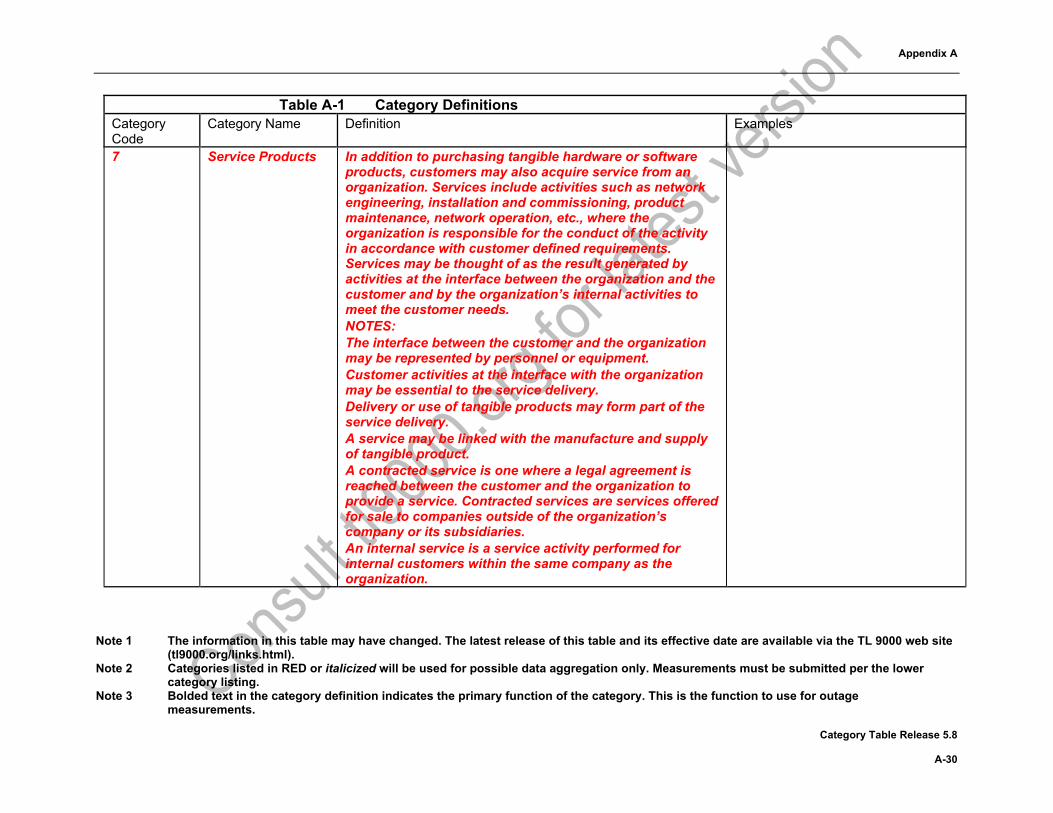
7 Service Products In addition to purchasing tangible hardware or software products, customers may also acquire service from an organization. Services include activities such as network engineering, installation and commissioning, product maintenance, network operation, etc., where the organization is responsible for the conduct of the activity in accordance with customer defined requirements. Services may be thought of as the result generated by activities at the interface between the organization and the customer and by the organization’s internal activities to meet the customer needs. NOTES: The interface between the customer and the organization may be represented by personnel or equipment. Customer activities at the interface with the organization may be essential to the service delivery. Delivery or use of tangible products may form part of the service delivery. A service may be linked with the manufacture and supply of tangible product. A contracted service is one where a legal agreement is reached between the customer and the organization to provide a service. Contracted services are services offered for sale to companies outside of the organization’s company or its subsidiaries. An internal service is a service activity performed for internal customers within the same company as the organization.
Appendix A
Note 1 The information in this table may have changed. The latest release of this table and its effective date are available via the TL 9000 web site (tl9000.org/links.html).
Note 2 Categories listed in RED or italicized will be used for possible data aggregation only. Measurements must be submitted per the lower category listing.
Note 3 Bolded text in the category definition indicates the primary function of the category. This is the function to use for outage measurements.
Category Table Release 5.8 A-31
Table A-1 Category Definitions Category Code
Category Name Definition Examples
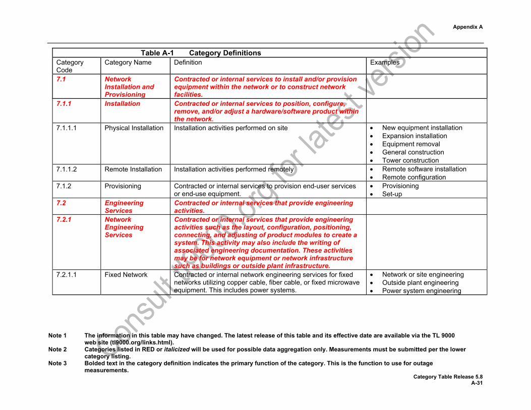
7.1 Network Installation and Provisioning
Contracted or internal services to install and/or provision equipment within the network or to construct network facilities.
7.1.1 Installation Contracted or internal services to position, configure, remove, and/or adjust a hardware/software product within the network.
7.1.1.1 Physical Installation Installation activities performed on site • New equipment installation • Expansion installation • Equipment removal • General construction • Tower construction
7.1.1.2 Remote Installation Installation activities performed remotely • Remote software installation • Remote configuration
7.1.2 Provisioning Contracted or internal services to provision end-user services or end-use equipment.
• Provisioning • Set-up
7.2 Engineering Services
Contracted or internal services that provide engineering activities.
7.2.1 Network Engineering Services
Contracted or internal services that provide engineering activities such as the layout, configuration, positioning, connecting, and adjusting of product modules to create a system. This activity may also include the writing of associated engineering documentation. These activities may be for network equipment or network infrastructure such as buildings or outside plant infrastructure.
7.2.1.1
Fixed Network Contracted or internal network engineering services for fixed networks utilizing copper cable, fiber cable, or fixed microwave equipment. This includes power systems.
• Network or site engineering • Outside plant engineering • Power system engineering
Appendix A
Note 1 The information in this table may have changed. The latest release of this table and its effective date are available via the TL 9000 web site (tl9000.org/links.html).
Note 2 Categories listed in RED or italicized will be used for possible data aggregation only. Measurements must be submitted per the lower category listing.
Note 3 Bolded text in the category definition indicates the primary function of the category. This is the function to use for outage measurements.
Category Table Release 5.8 A-32
Table A-1 Category Definitions Category Code
Category Name Definition Examples
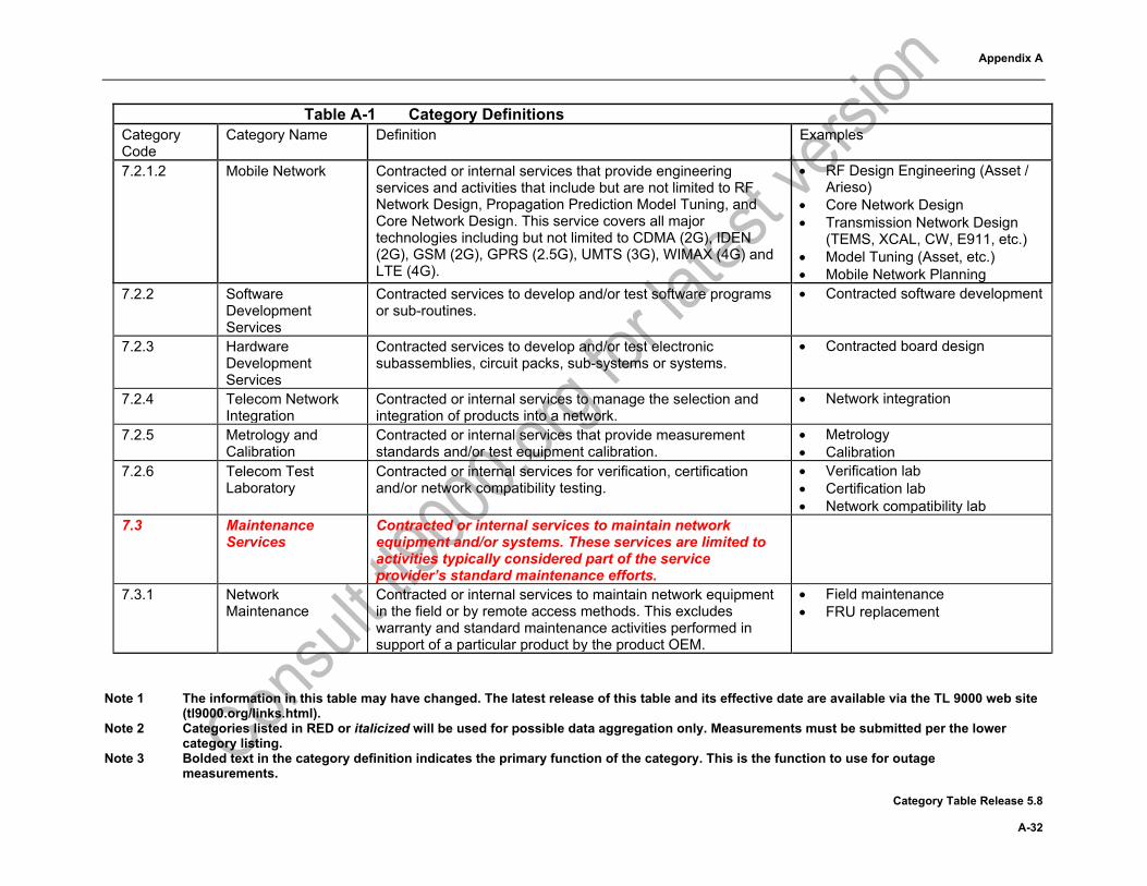
7.2.1.2 Mobile Network Contracted or internal services that provide engineering services and activities that include but are not limited to RF Network Design, Propagation Prediction Model Tuning, and Core Network Design. This service covers all major technologies including but not limited to CDMA (2G), IDEN (2G), GSM (2G), GPRS (2.5G), UMTS (3G), WIMAX (4G) and LTE (4G).
• RF Design Engineering (Asset / Arieso)
• Core Network Design • Transmission Network Design
(TEMS, XCAL, CW, E911, etc.) • Model Tuning (Asset, etc.) • Mobile Network Planning
7.2.2 Software Development Services
Contracted services to develop and/or test software programs or sub-routines.
• Contracted software development
7.2.3 Hardware Development Services
Contracted services to develop and/or test electronic subassemblies, circuit packs, sub-systems or systems.
• Contracted board design
7.2.4 Telecom Network Integration
Contracted or internal services to manage the selection and integration of products into a network.
• Network integration
7.2.5 Metrology and Calibration
Contracted or internal services that provide measurement standards and/or test equipment calibration.
• Metrology • Calibration
7.2.6 Telecom Test Laboratory
Contracted or internal services for verification, certification and/or network compatibility testing.
• Verification lab • Certification lab • Network compatibility lab
7.3 Maintenance Services
Contracted or internal services to maintain network equipment and/or systems. These services are limited to activities typically considered part of the service provider’s standard maintenance efforts.
7.3.1 Network Maintenance
Contracted or internal services to maintain network equipment in the field or by remote access methods. This excludes warranty and standard maintenance activities performed in support of a particular product by the product OEM.
• Field maintenance • FRU replacement
Appendix A
Note 1 The information in this table may have changed. The latest release of this table and its effective date are available via the TL 9000 web site (tl9000.org/links.html).
Note 2 Categories listed in RED or italicized will be used for possible data aggregation only. Measurements must be submitted per the lower category listing.
Note 3 Bolded text in the category definition indicates the primary function of the category. This is the function to use for outage measurements.
Category Table Release 5.8 A-33
Table A-1 Category Definitions Category Code
Category Name Definition Examples
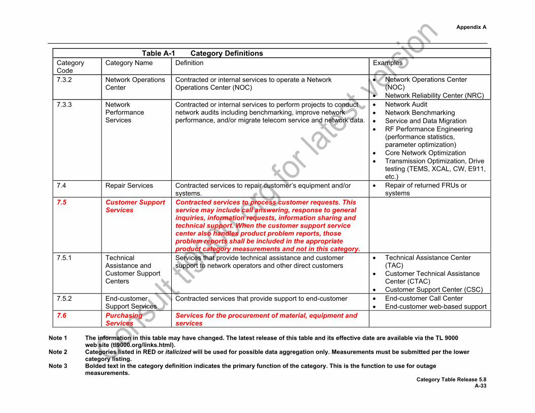
7.3.2 Network Operations Center
Contracted or internal services to operate a Network Operations Center (NOC)
• Network Operations Center (NOC)
• Network Reliability Center (NRC) 7.3.3 Network
Performance Services
Contracted or internal services to perform projects to conduct network audits including benchmarking, improve network performance, and/or migrate telecom service and network data.
• Network Audit • Network Benchmarking • Service and Data Migration • RF Performance Engineering
(performance statistics, parameter optimization)
• Core Network Optimization • Transmission Optimization, Drive
testing (TEMS, XCAL, CW, E911, etc.)
7.4 Repair Services Contracted services to repair customer’s equipment and/or systems.
• Repair of returned FRUs or systems
7.5 Customer Support Services
Contracted services to process customer requests. This service may include call answering, response to general inquiries, information requests, information sharing and technical support. When the customer support service center also handles product problem reports, those problem reports shall be included in the appropriate product category measurements and not in this category.
7.5.1 Technical Assistance and Customer Support Centers
Services that provide technical assistance and customer support to network operators and other direct customers
• Technical Assistance Center (TAC)
• Customer Technical Assistance Center (CTAC)
• Customer Support Center (CSC) 7.5.2 End-customer
Support Services Contracted services that provide support to end-customer • End-customer Call Center
• End-customer web-based support 7.6 Purchasing
Services Services for the procurement of material, equipment and services
Appendix A
Note 1 The information in this table may have changed. The latest release of this table and its effective date are available via the TL 9000 web site (tl9000.org/links.html).
Note 2 Categories listed in RED or italicized will be used for possible data aggregation only. Measurements must be submitted per the lower category listing.
Note 3 Bolded text in the category definition indicates the primary function of the category. This is the function to use for outage measurements.
Category Table Release 5.8 A-34
Table A-1 Category Definitions Category Code
Category Name Definition Examples
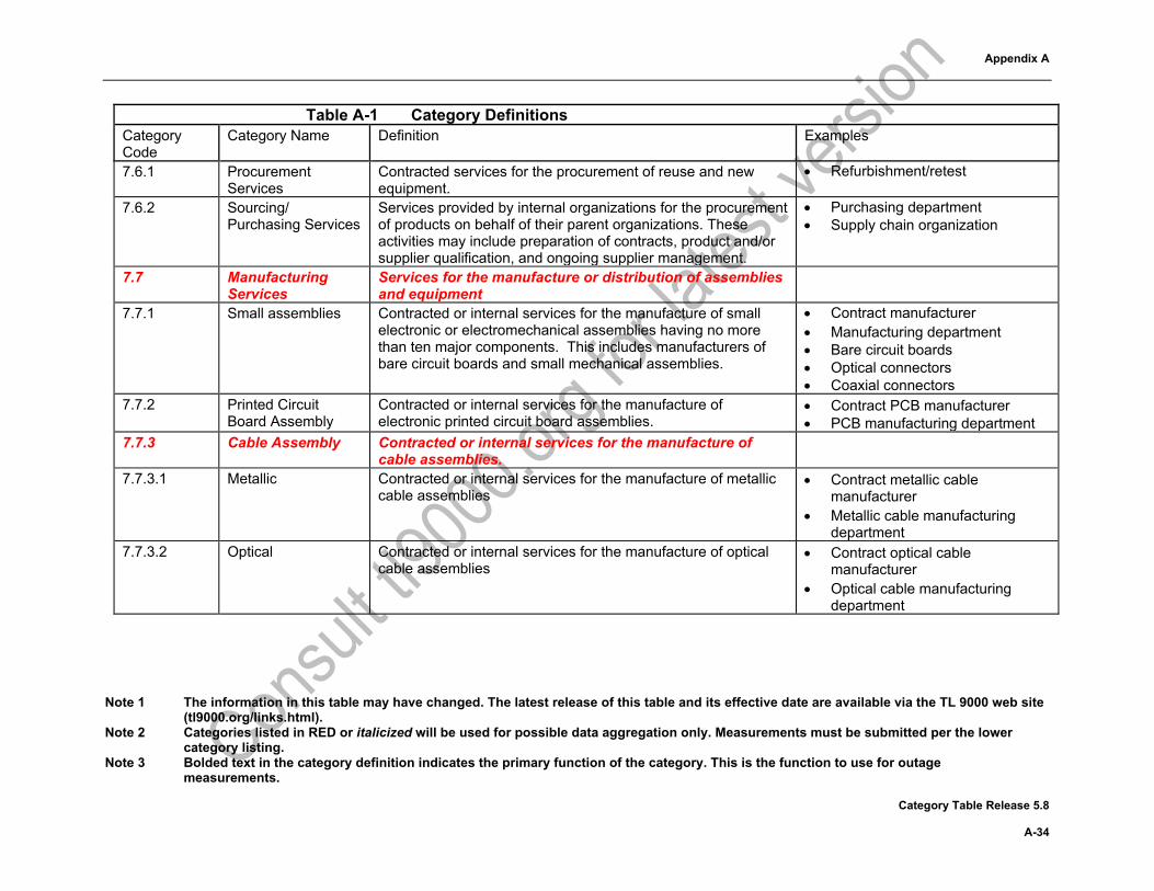
7.6.1 Procurement Services
Contracted services for the procurement of reuse and new equipment.
• Refurbishment/retest
7.6.2 Sourcing/ Purchasing Services
Services provided by internal organizations for the procurement of products on behalf of their parent organizations. These activities may include preparation of contracts, product and/or supplier qualification, and ongoing supplier management.
• Purchasing department • Supply chain organization
7.7 Manufacturing Services
Services for the manufacture or distribution of assemblies and equipment
7.7.1 Small assemblies Contracted or internal services for the manufacture of small electronic or electromechanical assemblies having no more than ten major components. This includes manufacturers of bare circuit boards and small mechanical assemblies.
• Contract manufacturer • Manufacturing department • Bare circuit boards • Optical connectors • Coaxial connectors
7.7.2 Printed Circuit Board Assembly
Contracted or internal services for the manufacture of electronic printed circuit board assemblies.
• Contract PCB manufacturer • PCB manufacturing department
7.7.3 Cable Assembly Contracted or internal services for the manufacture of cable assemblies.
7.7.3.1 Metallic Contracted or internal services for the manufacture of metallic cable assemblies
• Contract metallic cable manufacturer
• Metallic cable manufacturing department
7.7.3.2 Optical Contracted or internal services for the manufacture of optical cable assemblies
• Contract optical cable manufacturer
• Optical cable manufacturing department
Appendix A
Note 1 The information in this table may have changed. The latest release of this table and its effective date are available via the TL 9000 web site (tl9000.org/links.html).
Note 2 Categories listed in RED or italicized will be used for possible data aggregation only. Measurements must be submitted per the lower category listing.
Note 3 Bolded text in the category definition indicates the primary function of the category. This is the function to use for outage measurements.
Category Table Release 5.8 A-35
Table A-1 Category Definitions Category Code
Category Name Definition Examples
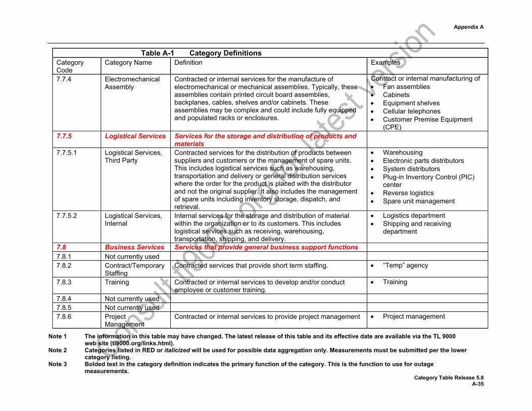
7.7.4 Electromechanical Assembly
Contracted or internal services for the manufacture of electromechanical or mechanical assemblies. Typically, these assemblies contain printed circuit board assemblies, backplanes, cables, shelves and/or cabinets. These assemblies may be complex and could include fully equipped and populated racks or enclosures.
Contract or internal manufacturing of • Fan assemblies • Cabinets • Equipment shelves • Cellular telephones • Customer Premise Equipment
(CPE) 7.7.5 Logistical Services Services for the storage and distribution of products and
materials
7.7.5.1 Logistical Services, Third Party
Contracted services for the distribution of products between suppliers and customers or the management of spare units. This includes logistical services such as warehousing, transportation and delivery or general distribution services where the order for the product is placed with the distributor and not the original supplier. It also includes the management of spare units including inventory storage, dispatch, and retrieval.
• Warehousing • Electronic parts distributors • System distributors • Plug-in Inventory Control (PIC)
center • Reverse logistics • Spare unit management
7.7.5.2 Logistical Services, Internal
Internal services for the storage and distribution of material within the organization or to its customers. This includes logistical services such as receiving, warehousing, transportation, shipping, and delivery.
• Logistics department • Shipping and receiving
department
7.8 Business Services Services that provide general business support functions 7.8.1 Not currently used 7.8.2 Contract/Temporary
Staffing Contracted services that provide short term staffing. • “Temp” agency
7.8.3 Training Contracted or internal services to develop and/or conduct employee or customer training.
• Training
7.8.4 Not currently used 7.8.5 Not currently used 7.8.6 Project
Management Contracted or internal services to provide project management • Project management

Appendix A
Note 1 The information in this table may have changed. The latest release of this table and its effective date are available via the TL 9000 web site (tl9000.org/links.html).
Note 2 Categories listed in RED or italicized will be used for possible data aggregation only. Measurements must be submitted per the lower category listing.
Note 3 Bolded text in the category definition indicates the primary function of the category. This is the function to use for outage measurements.
Category Table Release 5.8 A-36
Table A-1 Category Definitions Category Code
Category Name Definition Examples
7.9 General Support Services
Contracted or internal services that is not included in another service product category.
8 Components and Subassemblies
Individual components or assemblies provided for use in telecommunications systems excluding those already covered by a specific product category in another product or service family. These items are typically used by other suppliers and not sold directly to service providers except as replacement parts.
8.1 Hardware Components
Individual self-contained active or passive devices without separable parts not included in another category
8.1.1 Discrete semiconductors
Components typically performing a single function in electronic circuits, the purpose of which is switching, amplifying, or rectifying and transmitting signals.
• Diodes • Transistors • Optoelectronic devices
8.1.2 Integrated circuits A single structure containing many circuits and functions on a chip. These devices typically contain a considerable amount of intellectual property.
• ASICs • FPGAs • Microprocessors
8.1.3 Passive Components
Components that are used to store electrical charges, to limit or resist electrical current, and for filtering, surge suppression, measurement, timing, and tuning.
• Resistors • Capacitors • Inductors
8.1.4 Mechanical and Electromechanical
Mechanical and electromechanical devices not covered by another category such as 3.1.1.1.x, 3.1.1.2.x, 8.1.1, 8.1.2, 8.1.3, 8.1.5, 8.5.2.1, or 8.5.2.2
• Relays • Switches • Brackets • Cases • Mechanical components
8.1.5 Printed Circuit Boards
Bare printed circuit boards with no components attached • Bare PCBs

Appendix A
Note 1 The information in this table may have changed. The latest release of this table and its effective date are available via the TL 9000 web site (tl9000.org/links.html).
Note 2 Categories listed in RED or italicized will be used for possible data aggregation only. Measurements must be submitted per the lower category listing.
Note 3 Bolded text in the category definition indicates the primary function of the category. This is the function to use for outage measurements.
Category Table Release 5.8 A-37
Table A-1 Category Definitions Category Code
Category Name Definition Examples
8.2 Electronic Assemblies
A device made up of a number of electrical components for use in a telecommunications system. This device is a portion of the completed system but does not comprise the entire system.
8.2.1 Simple Less than 11 electrical components or 49 electrical connections excluding connectors
• VCXOs • Bandpass filters • MW circulators
8.2.2 Medium Complexity More than 10 electrical components or 48 electrical connections but less than 51 components or 241 electrical connections excluding connectors.
• Multi die hybrids • DC/DC converter “bricks”
8.2.3 High Complexity More than 50 electrical components or 240 electrical connections but less than 501 components or 2401 electrical connections excluding connectors
• Medium sized printed circuit assemblies
• Backplane assemblies 8.2.4 Very High
Complexity More than 500 electrical components or 2400 electrical connections excluding connectors
• Single board computers • “Pizza Box” servers • Blade servers
8.3 Cable Assemblies Internal and/or external connectorized metallic or fiber optic cable assemblies
• Telco • D-Sub • Coax • Harnesses
8.4 Electromechanical Assemblies
Devices or assemblies that are mechanical or electrical-mechanical in nature. Typically, the electromechanical assemblies contain PCBAs, backplanes, cables and/or cable assemblies. These assemblies may be complex and could include fully equipped and populated racks or enclosures.
• Fan assembly • Rack assemblies • Cabinets • Equipment shelves
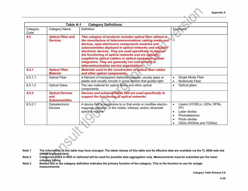
Appendix A
Note 1 The information in this table may have changed. The latest release of this table and its effective date are available via the TL 9000 web site (tl9000.org/links.html).
Note 2 Categories listed in RED or italicized will be used for possible data aggregation only. Measurements must be submitted per the lower category listing.
Note 3 Bolded text in the category definition indicates the primary function of the category. This is the function to use for outage measurements.
Category Table Release 5.8 A-38
Table A-1 Category Definitions Category Code
Category Name Definition Examples
8.5 Optical Fiber and Devices
This category of products includes optical fiber utilized in the manufacture of telecommunications cabling media and devices, opto-electronics components modules and subassemblies deployed in optical networks and ancillary electronic devices. They are used specifically to support the functioning of optical networks and are typically supplied to optical cablers or optical equipment system integrators. They are generally not sold directly to telecommunication service organizations.
8.5.1 Optical Fiber Material
Materials used in the construction of optical fiber cables and other optical components.
8.5.1.1 Optical Fiber A filament of transparent dielectric material, usually glass or plastic and usually circular in cross section that guides light.
• Single Mode Fiber • Multimode Fiber
8.5.1.2 Optical Glass The raw material for optical fibers and other optical components
• Optical glass
8.5.2 Optical Devices and Subassemblies
Devices and subassemblies that are used specifically to support the functioning of optical networks
8.5.2.1 Optoelectronic Devices
A device that is responsive to or that emits or modifies electro-magnetic radiation, in the visible, infrared, and/or ultraviolet spectral regions.
• Lasers (VCSELs, LEDs, DFBs, FP)
• Laser diodes • Photodetectors • Photo diodes • OSAs (ROSAs and TOSAs)

Appendix A
Note 1 The information in this table may have changed. The latest release of this table and its effective date are available via the TL 9000 web site (tl9000.org/links.html).
Note 2 Categories listed in RED or italicized will be used for possible data aggregation only. Measurements must be submitted per the lower category listing.
Note 3 Bolded text in the category definition indicates the primary function of the category. This is the function to use for outage measurements.
Category Table Release 5.8 A-39
Table A-1 Category Definitions Category Code
Category Name Definition Examples
8.5.2.2 Passive Optical Devices
A class of optical devices that either channels or filters an optical signal among ports in a non-variable predetermined fashion. It does not contain an optical source, detector or optoelectronic transducer of any kind and does not require external power.
• Isolators • Filters • Splitters • Mirrors • Lenses • Passive multiplexer • Passive demultiplexer
8.5.2.3 Optical Subassemblies
Stand-alone or “drop-in” products that perform a complete optical operation and may contain passive and/or optoelectronic devices. These subassemblies generally contain active optical devices (8.5.2.1), passive optical devices (8.5.2.2) and/or other types of components such as heaters, TECS, and standard electronic devices (8.1). These subassemblies are then used as part of an electronic assembly (8.2.x).
• Optical transmitter • Optical transceivers • Optical receiver • External modulator (packaged
with a laser) • Fiber optic amplifiers/EDFAs • Repeaters • Transponders • Optical MEMs

Appendix A
Note 1 The information in this table may have changed. The latest release of this table and its effective date are available via the TL 9000 web site (tl9000.org/links.html).
Note 2 Categories listed in RED or italicized will be used for possible data aggregation only. Measurements must be submitted per the lower category listing.
Note 3 Bolded text in the category definition indicates the primary function of the category. This is the function to use for outage measurements.
Category Table Release 5.8 A-40
Table A-1 Category Definitions Category Code
Category Name Definition Examples
8.6 Software Components and Tools
Software programs, routines, or sub-routines for use within other software programs or systems or for use in the development of other programs or systems.
• Protocol stacks • Operating systems • Sort routines • Database programs • Interface programs • Drivers • Compilers • Configuration management • Problem tracing and
management • Complexity measurement tools • Website tools • Multimedia tools • Static analysis tools • Simulators • Measurement tools • Code coverage tools • Porting and conversion
tools/services

Appendix A
Note 1 The information in this table may have changed. The latest release of this table and its effective date are available via the TL 9000 web site (tl9000.org/links.html).
Note 2 Categories listed in RED or italicized will be used for possible data aggregation only. Measurements must be submitted per the lower category listing.
Note 3 Bolded text in the category definition indicates the primary function of the category. This is the function to use for outage measurements.
Category Table Release 5.8 A-41
Table A-1 Category Definitions Category Code
Category Name Definition Examples
9 End-Customer Services
End-user consumer and business customers acquire a vast variety of products from a service provider organization. These may be supplied on a buy, lease or rental basis and comprise services from simple pre-paid wireless phone service to complex solutions or outsourced facilities management of a customer organization’s entire telecommunications facilities.
9.1 Voice Service products offered to business/public customers and to consumers, to support voice communications and supplementary services.
• Fixed voice access • Local services calls • Long distance and international
calls • Charge card/calling cards • Voice over IP (VoIP)
9.2 Wireless Service products offered to business/public customers and to consumers, to support mobile communications and service needs.
• Mobile voice • Paging • Small message service (SMS) • GPRS/3G message/visuals • WAP protocol services
9.3 Transport Networks Service products provided to business customers or other operators, to allow them to connect two or more physical sites as a communications network, either through multiple point-to-point services, or via a multi-point network.
• International private leased circuit • Analogue private circuit • Managed bandwidth • X25 packet switching • Unbundled local loop
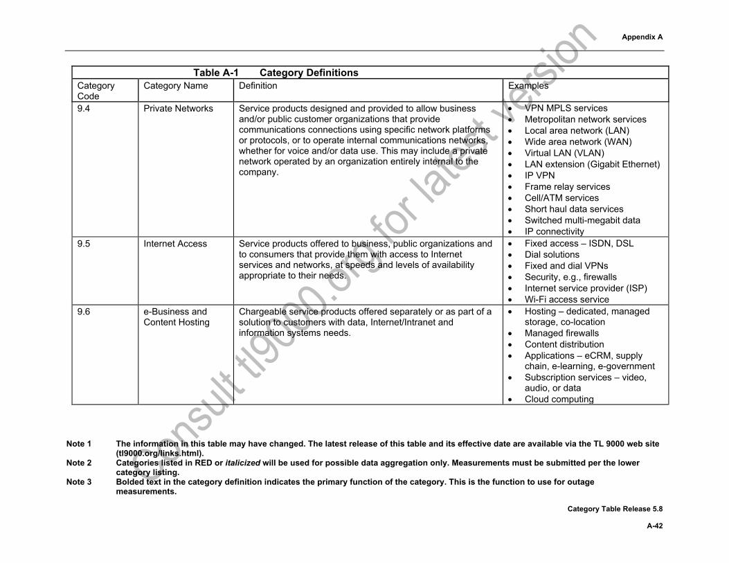
Appendix A
Note 1 The information in this table may have changed. The latest release of this table and its effective date are available via the TL 9000 web site (tl9000.org/links.html).
Note 2 Categories listed in RED or italicized will be used for possible data aggregation only. Measurements must be submitted per the lower category listing.
Note 3 Bolded text in the category definition indicates the primary function of the category. This is the function to use for outage measurements.
Category Table Release 5.8 A-42
Table A-1 Category Definitions Category Code
Category Name Definition Examples
9.4 Private Networks Service products designed and provided to allow business and/or public customer organizations that provide communications connections using specific network platforms or protocols, or to operate internal communications networks, whether for voice and/or data use. This may include a private network operated by an organization entirely internal to the company.
• VPN MPLS services • Metropolitan network services • Local area network (LAN) • Wide area network (WAN) • Virtual LAN (VLAN) • LAN extension (Gigabit Ethernet) • IP VPN • Frame relay services • Cell/ATM services • Short haul data services • Switched multi-megabit data • IP connectivity
9.5 Internet Access Service products offered to business, public organizations and to consumers that provide them with access to Internet services and networks, at speeds and levels of availability appropriate to their needs.
• Fixed access – ISDN, DSL • Dial solutions • Fixed and dial VPNs • Security, e.g., firewalls • Internet service provider (ISP) • Wi-Fi access service
9.6 e-Business and Content Hosting
Chargeable service products offered separately or as part of a solution to customers with data, Internet/Intranet and information systems needs.
• Hosting – dedicated, managed storage, co-location
• Managed firewalls • Content distribution • Applications – eCRM, supply
chain, e-learning, e-government • Subscription services – video,
audio, or data • Cloud computing

Appendix A
Note 1 The information in this table may have changed. The latest release of this table and its effective date are available via the TL 9000 web site (tl9000.org/links.html).
Note 2 Categories listed in RED or italicized will be used for possible data aggregation only. Measurements must be submitted per the lower category listing.
Note 3 Bolded text in the category definition indicates the primary function of the category. This is the function to use for outage measurements.
Category Table Release 5.8 A-43
Table A-1 Category Definitions Category Code
Category Name Definition Examples
9.7 Bulk Transport Services provided to other licensed operators or carriers to allow them to operate networks or services, without necessarily owning 100% of their operating network.
9.7.1 Infrastructure Service products that provide network infrastructure on a lease or rental basis, on long or short-term contracts.
• Wavelength • Dark fiber • Duct • Satellite services
9.7.2 Wholesale Service products provided to allow operators to trade traffic on a correspondent basis or to offer services without having to maintain a network of their own.
• Wholesale voice • Wholesale long distance • Wholesale IP • Outbound voice • Inbound voice
9.8 Video Broadcast Services
Service products that provide broadcast video to subscribers • Cable TV • Satellite TV • Video over fiber • IPTV
9.9 Emergency Service Network
Service to provide an emergency services network • E911 network • E112 network
Appendix A
Note 1 The information in this table may have changed. The latest release of this table and its effective date are available via the TL 9000 web site (tl9000.org/links.html).
Note 2 Categories listed in RED or italicized will be used for possible data aggregation only. Measurements must be submitted per the lower category listing.
Note 3 Bolded text in the category definition indicates the primary function of the category. This is the function to use for outage measurements.
Category Table Release 5.8 A-44
This page intentionally left blank

Appendix A
Category Table Release 5.8 A-45
Table A-2 Measurement Applicability Table (Normalization Units)
a) Measurements Without Normalization Factors The measurements Fix Response Time (FRT), Overdue Fix Responsiveness (OFR), and On-Time Delivery (OTD) are applicable and required for ALL categories. The measurements FRT, OFR and OTD do not require product specific normalization. In the interest of saving space, they are not listed in the following table, but data must be submitted for each of these three measurements in all product categories. Table A-2 defines the normalization units and applicability of the other measurements.
b) Other Rules and References
i) Where the normalization factor is traffic capacity based, such as DS1, Gigabit, DSL or Terminations, the calculation shall be based on the true usable traffic capacity. Equipment within the system used to provide protection for the main traffic path shall not be included, as it does not add usable capacity to the system.
ii) The column headings in Table A-2 are general descriptions covering several sub-measurements in some cases. For cross-references to the detailed descriptions of the measurements elsewhere in this document, refer to the measurement and sub-measurement symbols in Table A-6 and Table A-7.
iii) For some product categories, it may not be clear what is to be considered a unit. The following is added as an aid for the listed categories:
7.6.1 – a procured item 8.6 – an issued copy or licensed user
iv) For Category 7 Services, where the Normalization Unit (NU) may have a duration spanning more than one month (e.g., Job, Contract, Order), the number of NUs to be reported may be either the quantity started or the quantity accomplished during the reporting month, as long as the same method is used consistently.
v) An optical channel, for the purposes of TL 9000 normalization factor calculation, is defined as an individual wavelength of light.
vi) The measurements examples on the tl9000.org web site contain specific examples of techniques and methods for calculating normalization factors.
c) Measurement Summary Listing
Table A-6 is a listing of the measurements included in this handbook with the symbols used in data reporting, the applicability to hardware, software, and/or services (H, S, V), and a reference to the table in this handbook with data reporting details. The symbols listed here are referenced by the normalization unit and applicability table to clarify the general descriptions used as column headings.

Appendix A
Note 1 The information in this table may have changed. The latest release of this table and its effective date are available via the TL 9000 website (tl9000.org/links.html).
Note 2 Measurements FRT, OFR & OTD are applicable and must be reported for all categories. Note 3 Categories listed in RED or italicized will be used for possible data aggregation only. Measurements must be submitted per the lower
category listing. Note 4 If the normalization factor contains the word “shipped”, then the quantity shipped in the 12 months ending with the month being reported
shall be used. Category Table Release 5.8 A-46
Table A-2 Measurement Applicability Table (Normalization Units)
Category
Problem Reports
H, S, V
Outage Measurements Return Rate Software
Measurements
Code Description Service Impact
H, S
Network Element Impact
H, S
Field
Replaceable Unit Returns
H
Basic Return Rate
H
Software Fix Quality
S
Early Software Problem Report
S
TL 9000 Measurement Symbols (see Table A-6) NPR SO SONE FR BRR SFQ eSPR 1 Switching 1.1h Circuit Switch – all non-remotes including
host systems Network Element Termination Network Element Required NA Required Required
1.1r Circuit Switch – remotes only NA Termination Network Element NA NA NA NA
NOTE: All organizations registering in 1.1 shall report data for 1.1h and 1.1r in one data submission. If there are no remote applications for their product, then “EXEMPT” shall be entered in the 1.1r data. Data for measurements indicated “EXEMPT” for 1.1r is to be reported in combination with the host data in 1.1h.
NOTE: For MSC, terminations should equate to configured channels. 1.2 Packet Switch 1.2.1 Not currently used 1.2.2 Access Multi-service 1.2.2.1 Wireline Network Element Network Element Network Element Required NA Required Required 1.2.2.2 Wireless Network Element Network Element Network Element Required NA Required Required 1.2.2.3 Virtualized Network Element Network Element Network Element NA NA Required Required 1.2.3 Media Gateways Network Element Network Element Network Element Required NA Required Required 1.2.4 Core and Access Ethernet Switches 1.2.4.1 Legacy Ethernet Switches Network Element Network Element Network Element Required NA Required Required 1.2.4.2 Virtualized Ethernet Switches Network Element Network Element Network Element NA NA Required Required 1.2.5 Not currently used 1.2.6 Not currently used

Appendix A
Note 1 The information in this table may have changed. The latest release of this table and its effective date are available via the TL 9000 website
(tl9000.org/links.html). Note 2 Measurements FRT, OFR & OTD are applicable and must be reported for all categories. Note 3 Categories listed in RED or italicized will be used for possible data aggregation only. Measurements must be submitted per the lower
category listing. Note 4 If the normalization factor contains the word “shipped”, then the quantity shipped in the 12 months ending with the month being reported
shall be used. Category Table Release 5.8 A-47
Table A-2 Measurement Applicability Table (Normalization Units) Category
Problem Reports
H, S, V
Outage Measurements Return Rate Software
Measurements
Code Description Service Impact
H, S
Network Element Impact
H, S
Field
Replaceable Unit Returns
H
Basic Return Rate
H
Software Fix Quality
S
Early Software Problem Report
S
TL 9000 Measurement Symbols (see Table A-6) NPR SO SONE FR BRR SFQ eSPR 1.2.7 Application Servers Network Element Network Element Network Element Required NA Required Required 1.2.8 Service and Network Controller (SNC) Network Element Maximum
Configured Call Capacity
Network Element Required NA Required Required
1.2.9 Routers 1.2.9.1 Core 1.2.9.1.1 Legacy Core Routers Network Element Network Element Network Element Required NA Required Required 1.2.9.1.2 Virtualized Core Routers Network Element Network Element Network Element NA NA Required Required 1.2.9.2 Edge 1.2.9.2.1 Legacy Edge Routers Network Element Network Element Network Element Required NA Required Required 1.2.9.2.2 Virtualized Edge Routers Network Element Network Element Network Element NA NA Required Required 1.2.9.3 Access Network Element Network Element Network Element Required NA Required Required 2 Signaling and Network Control 2.1 Service Control {Formerly Service Control
Point (SCP)}
Network Element Network Element Network Element Required NA Required Required
2.2 Signaling Controller Network Element Network Element Network Element Required NA Required Required 2.3 Home Location Register (HLR) Network Element Network Element Network Element Required NA Required Required 2.4 Not currently used 2.5 Protocol Servers Network Element Network Element Network Element Required NA Required Required 2.6 Network Access Control Network Element Network Element Network Element Required NA Required Required

Appendix A
Note 1 The information in this table may have changed. The latest release of this table and its effective date are available via the TL 9000 website (tl9000.org/links.html).
Note 2 Measurements FRT, OFR & OTD are applicable and must be reported for all categories. Note 3 Categories listed in RED or italicized will be used for possible data aggregation only. Measurements must be submitted per the lower
category listing. Note 4 If the normalization factor contains the word “shipped”, then the quantity shipped in the 12 months ending with the month being reported
shall be used. Category Table Release 5.8 A-48
Table A-2 Measurement Applicability Table (Normalization Units) Category
Problem Reports
H, S, V
Outage Measurements Return Rate Software
Measurements
Code Description Service Impact
H, S
Network Element Impact
H, S
Field
Replaceable Unit Returns
H
Basic Return Rate
H
Software Fix Quality
S
Early Software Problem Report
S
TL 9000 Measurement Symbols (see Table A-6) NPR SO SONE FR BRR SFQ eSPR 2.7 Not currently used 2.8 Mobility Management Entity (MME) Network Element Network Element Network Element Required NA Required Required 3 Transmission Systems 3.1 Transmission Media and Structure
(Outside Plant)
3.1.1 Transmission Medium 3.1.1.1 Metallic Products 3.1.1.1.1 Metallic Conductor Cable Finished product
,million meters shipped
NA NA NA NA NA NA
3.1.1.1.2 Metallic Connectors Units shipped NA NA NA NA NA NA 3.1.1.2 Fiber Optic Cable Products 3.1.1.2.1 Fiber Optic Cable Finished product
million meters shipped
NA NA NA NA NA NA
3.1.1.2.2 Optical connectors Units shipped NA NA NA NA NA NA 3.1.1.3 Transmission Sub-systems 3.1.1.3.1 Not currently used 3.1.1.3.2 Passive Optical Sub-systems Units shipped NA NA NA Required NA NA 3.1.1.3.3 Other Sub-systems Unit shipped NA NA NA Required NA NA 3.1.1.3.4 Fixed Antenna Systems Network Element NA NA NA Required NA NA

Appendix A
Note 1 The information in this table may have changed. The latest release of this table and its effective date are available via the TL 9000 website
(tl9000.org/links.html). Note 2 Measurements FRT, OFR & OTD are applicable and must be reported for all categories. Note 3 Categories listed in RED or italicized will be used for possible data aggregation only. Measurements must be submitted per the lower
category listing. Note 4 If the normalization factor contains the word “shipped”, then the quantity shipped in the 12 months ending with the month being reported
shall be used. Category Table Release 5.8 A-49
Table A-2 Measurement Applicability Table (Normalization Units) Category
Problem Reports
H, S, V
Outage Measurements Return Rate Software
Measurements
Code Description Service Impact
H, S
Network Element Impact
H, S
Field
Replaceable Unit Returns
H
Basic Return Rate
H
Software Fix Quality
S
Early Software Problem Report
S
TL 9000 Measurement Symbols (see Table A-6) NPR SO SONE FR BRR SFQ eSPR 3.1.2 Physical Structure 3.1.2.1 Enclosures Units shipped NA NA NA Required NA NA 3.1.2.2 Support Structures Units shipped NA NA NA Required NA NA 3.1.2.3 Conduits Meters shipped NA NA NA Required NA NA 3.2 Transport Equipment 3.2.1 Manual Cross Connect Systems Network Element NA NA Required NA NA NA 3.2.2 Carrier Systems/Multiplexers 3.2.2.1 Interoffice/Long Haul 3.2.2.1.1 Metallic Carrier Systems Network Element DS1 Network Element Required NA Required Required 3.2.2.1.2 Optical Carrier Systems 3.2.2.1.2.1 Optical Transport Systems Network Element Gigabit Network Element Required NA Required Required 3.2.2.1.2.2 WDM/DWDM/Optical Amplification Network Element Optical Channel Network Element Required NA Required Required 3.2.2.1.2.3 Reconfigurable Optical Add-Drop
Multiplexer (ROADM) Network Element Optical Channel Network Element Required NA Required Required
3.2.2.1.3 Microwave Network Element DS1 Network Element Required NA Required Required 3.2.2.2 Loop Carrier Network Element DS1 Network Element Required NA Required Required 3.2.3 Not currently used 3.2.4 Digital Subscriber Line (DSL) Network Element DSL Network Element Required NA Required Required 3.2.5 Fiber to the User Network Element Subscriber Network Element Required NA Required Required 3.2.6 Video Transmission Equipment Network Element Network Element Network Element Required NA Required Required

Appendix A
Note 1 The information in this table may have changed. The latest release of this table and its effective date are available via the TL 9000 website (tl9000.org/links.html).
Note 2 Measurements FRT, OFR & OTD are applicable and must be reported for all categories. Note 3 Categories listed in RED or italicized will be used for possible data aggregation only. Measurements must be submitted per the lower
category listing. Note 4 If the normalization factor contains the word “shipped”, then the quantity shipped in the 12 months ending with the month being reported
shall be used. Category Table Release 5.8 A-50
Table A-2 Measurement Applicability Table (Normalization Units) Category
Problem Reports
H, S, V
Outage Measurements Return Rate Software
Measurements
Code Description Service Impact
H, S
Network Element Impact
H, S
Field
Replaceable Unit Returns
H
Basic Return Rate
H
Software Fix Quality
S
Early Software Problem Report
S
TL 9000 Measurement Symbols (see Table A-6) NPR SO SONE FR BRR SFQ eSPR 3.3 Wireless Transmission 3.3.1 Base Station Controller Equipment Network Element Network Element Network Element Required NA Required Required 3.3.2 Base Transceiver System (BTS) 3.3.2.1 Basic Network Element Network Element Network Element Required NA Required Required 3.3.2.2 Advanced Network Element Network Element Network Element Required NA Required Required 3.3.2.3 4G Network Element Network Element Network Element Required NA Required Required 3.3.2.4 Small Cell Radios Network Element Network Element Network Element Required NA Required Required 3.3.2.5 Combined Network Element Network Element Network Element Required NA Required Required 3.3.2.6 5G Network Element Network Element Network Element Required NA Required Required 3.3.3 Not currently used 3.3.4 WLAN Base Station Equipment Network Element Network Element Network Element Required NA Required Required 3.3.5 Open Radio Access Network (Open
RAN)
3.3.5.1 Remote Radio Unit (RRU) Network Element Network Element Network Element Required NA Required Required 3.3.5.2 Virtualized Baseband Unit (BBU) System System System NA NA Required Required 3.3.5.3 Virtualized Central Unit (CU) System System System NA NA Required Required 3.3.5.4 Virtualized Control Plane (CUCP) System System System NA NA Required Required 3.3.5.5 Virtualized User Plane (CUUP) System System System NA NA Required Required 3.3.5.6 Virtualized Distribution Unit (DU) System System System NA NA Required Required 3.4 Ancillary Products 3.4.1 Location Services Network Element Network Element Network Element Required NA Required Required
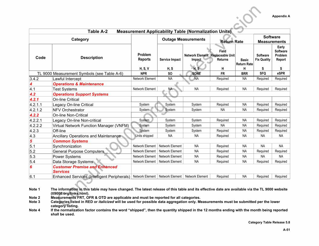
Appendix A
Note 1 The information in this table may have changed. The latest release of this table and its effective date are available via the TL 9000 website
(tl9000.org/links.html). Note 2 Measurements FRT, OFR & OTD are applicable and must be reported for all categories. Note 3 Categories listed in RED or italicized will be used for possible data aggregation only. Measurements must be submitted per the lower
category listing. Note 4 If the normalization factor contains the word “shipped”, then the quantity shipped in the 12 months ending with the month being reported
shall be used. Category Table Release 5.8 A-51
Table A-2 Measurement Applicability Table (Normalization Units) Category
Problem Reports
H, S, V
Outage Measurements Return Rate Software
Measurements
Code Description Service Impact
H, S
Network Element Impact
H, S
Field
Replaceable Unit Returns
H
Basic Return Rate
H
Software Fix Quality
S
Early Software Problem Report
S
TL 9000 Measurement Symbols (see Table A-6) NPR SO SONE FR BRR SFQ eSPR 3.4.2 Lawful Intercept Network Element NA NA Required NA Required Required 4 Operations & Maintenance 4.1 Test Systems Network Element NA NA Required NA Required Required 4.2 Operations Support Systems 4.2.1 On-line Critical 4.2.1.1 Legacy On-line Critical System System System Required NA Required Required 4.2.1.2 NFV Orchestrator System System System NA NA Required Required 4.2.2 On-line Non-Critical 4.2.2.1 Legacy On-line Non-critical System System System Required NA Required Required 4.2.2.2 Virtual Network Function Manager (VNFM) System System System NA NA Required Required 4.2.3 Off-line System System System Required NA Required Required 4.3 Ancillary Operations and Maintenance Units shipped NA NA Required NA NA NA 5 Common Systems 5.1 Synchronization Network Element Network Element NA Required NA NA NA 5.2 General Purpose Computers Network Element Network Element NA Required NA Required Required 5.3 Power Systems Network Element Network Element NA Required NA NA NA 5.4 Data Storage Systems Network Element Network Element NA Required NA Required Required 6 Customer Premise and Enhanced
Services
6.1 Enhanced Services (Intelligent Peripherals) Network Element Network Element Network Element Required NA Required Required
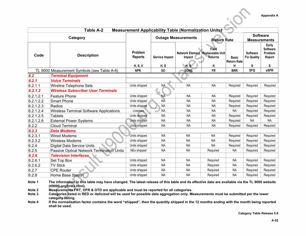
Appendix A
Note 1 The information in this table may have changed. The latest release of this table and its effective date are available via the TL 9000 website (tl9000.org/links.html).
Note 2 Measurements FRT, OFR & OTD are applicable and must be reported for all categories. Note 3 Categories listed in RED or italicized will be used for possible data aggregation only. Measurements must be submitted per the lower
category listing. Note 4 If the normalization factor contains the word “shipped”, then the quantity shipped in the 12 months ending with the month being reported
shall be used. Category Table Release 5.8 A-52
Table A-2 Measurement Applicability Table (Normalization Units) Category
Problem Reports
H, S, V
Outage Measurements Return Rate Software
Measurements
Code Description Service Impact
H, S
Network Element Impact
H, S
Field
Replaceable Unit Returns
H
Basic Return Rate
H
Software Fix Quality
S
Early Software Problem Report
S
TL 9000 Measurement Symbols (see Table A-6) NPR SO SONE FR BRR SFQ eSPR 6.2 Terminal Equipment 6.2.1 Voice Terminals 6.2.1.1 Wireline Telephone Sets Units shipped NA NA NA Required Required Required 6.2.1.2 Wireless Subscriber User Terminals 6.2.1.2.1 Feature Phone Units shipped NA NA NA Required Required Required 6.2.1.2.2 Smart Phone Units shipped NA NA NA Required Required Required 6.2.1.2.3 Radios Units shipped NA NA NA Required Required Required 6.2.1.2.4 Wireless Terminal Software Applications Licenses NA NA NA NA Required Required 6.2.1.2.5 Tablets Units shipped NA NA NA Required Required Required 6.2.1.2.6 External Power Systems Units shipped NA NA NA Required NA NA 6.2.2 Cloud Terminal Units shipped NA NA NA Required Required Required 6.2.3 Data Modems 6.2.3.1 Wired Modems Units shipped NA NA NA Required Required Required 6.2.3.2 Wireless Modems Units shipped NA NA NA Required Required Required 6.2.4 Digital Data Service Units Units shipped NA NA NA Required Required Required 6.2.5 Passive Optical Network Termination Units NEs shipped NA NA Required NA Required Required 6.2.6 Television Interfaces 6.2.6.1 Set Top Box Units shipped NA NA Required NA Required Required 6.2.6.2 TV Stick Units shipped NA NA Required NA Required Required 6.2.7 CPE Router Units shipped NA NA Required NA Required Required 6.2.8 Home Base Station Units shipped NA NA Required NA Required Required
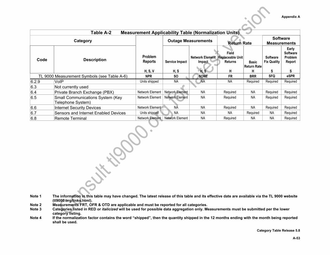
Appendix A
Note 1 The information in this table may have changed. The latest release of this table and its effective date are available via the TL 9000 website
(tl9000.org/links.html). Note 2 Measurements FRT, OFR & OTD are applicable and must be reported for all categories. Note 3 Categories listed in RED or italicized will be used for possible data aggregation only. Measurements must be submitted per the lower
category listing. Note 4 If the normalization factor contains the word “shipped”, then the quantity shipped in the 12 months ending with the month being reported
shall be used. Category Table Release 5.8 A-53
Table A-2 Measurement Applicability Table (Normalization Units) Category
Problem Reports
H, S, V
Outage Measurements Return Rate Software
Measurements
Code Description Service Impact
H, S
Network Element Impact
H, S
Field
Replaceable Unit Returns
H
Basic Return Rate
H
Software Fix Quality
S
Early Software Problem Report
S
TL 9000 Measurement Symbols (see Table A-6) NPR SO SONE FR BRR SFQ eSPR 6.2.9 VoIP Units shipped NA NA NA Required Required Required 6.3 Not currently used 6.4 Private Branch Exchange (PBX) Network Element Network Element NA Required NA Required Required 6.5 Small Communications System (Key
Telephone System) Network Element Network Element NA Required NA Required Required
6.6 Internet Security Devices Network Element NA NA Required NA Required Required 6.7 Sensors and Internet Enabled Devices Units shipped NA NA NA Required NA Required 6.8 Remote Terminal Network Element Network Element NA Required NA NA Required
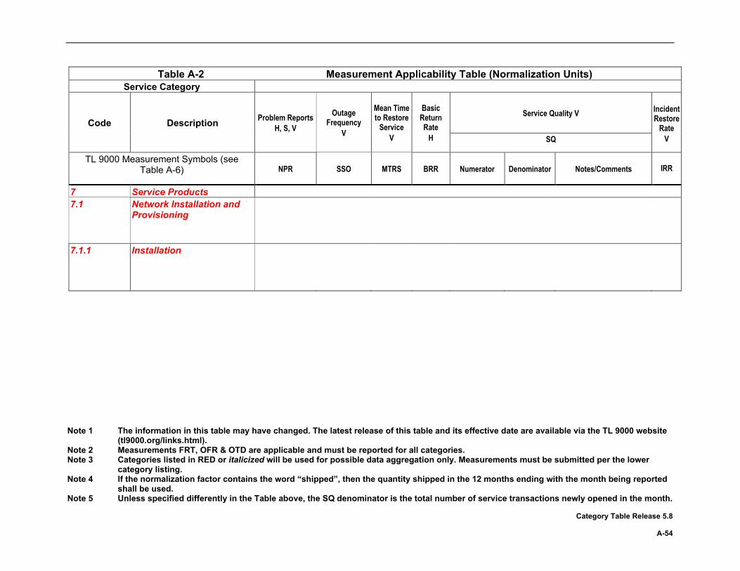
Note 1 The information in this table may have changed. The latest release of this table and its effective date are available via the TL 9000 website (tl9000.org/links.html).
Note 2 Measurements FRT, OFR & OTD are applicable and must be reported for all categories. Note 3 Categories listed in RED or italicized will be used for possible data aggregation only. Measurements must be submitted per the lower
category listing. Note 4 If the normalization factor contains the word “shipped”, then the quantity shipped in the 12 months ending with the month being reported
shall be used. Note 5 Unless specified differently in the Table above, the SQ denominator is the total number of service transactions newly opened in the month. Category Table Release 5.8 A-54
Table A-2 Measurement Applicability Table (Normalization Units) Service Category
Code Description Problem Reports H, S, V
Outage Frequency
V
Mean Time to Restore
Service V
Basic Return Rate
H
Service Quality V
Incident Restore
Rate V SQ
TL 9000 Measurement Symbols (see Table A-6) NPR SSO MTRS BRR Numerator Denominator Notes/Comments
IRR
7 Service Products 7.1 Network Installation and
Provisioning
7.1.1 Installation
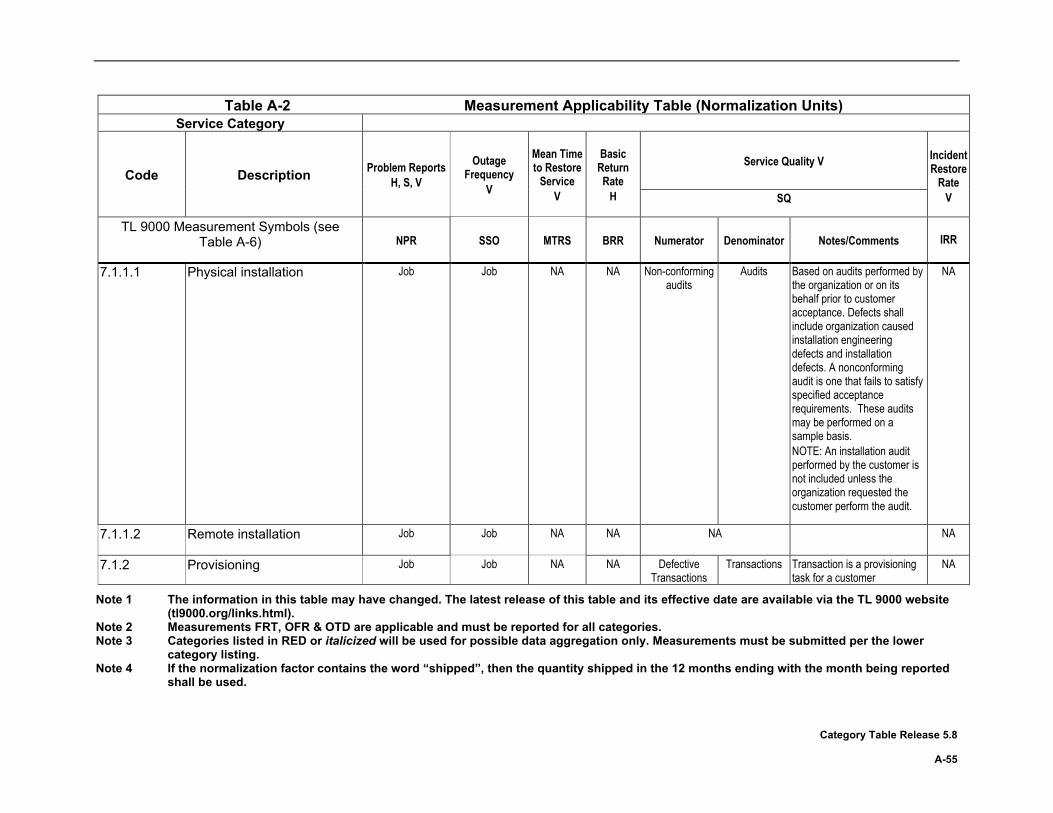
Note 1 The information in this table may have changed. The latest release of this table and its effective date are available via the TL 9000 website (tl9000.org/links.html).
Note 2 Measurements FRT, OFR & OTD are applicable and must be reported for all categories. Note 3 Categories listed in RED or italicized will be used for possible data aggregation only. Measurements must be submitted per the lower
category listing. Note 4 If the normalization factor contains the word “shipped”, then the quantity shipped in the 12 months ending with the month being reported
shall be used. Category Table Release 5.8 A-55
Table A-2 Measurement Applicability Table (Normalization Units) Service Category
Code Description Problem Reports H, S, V
Outage Frequency
V
Mean Time to Restore
Service V
Basic Return Rate
H
Service Quality V
Incident Restore
Rate V SQ
TL 9000 Measurement Symbols (see Table A-6) NPR SSO MTRS BRR Numerator Denominator Notes/Comments
IRR
7.1.1.1 Physical installation
Job Job NA NA Non-conforming audits
Audits Based on audits performed by the organization or on its behalf prior to customer acceptance. Defects shall include organization caused installation engineering defects and installation defects. A nonconforming audit is one that fails to satisfy specified acceptance requirements. These audits may be performed on a sample basis. NOTE: An installation audit performed by the customer is not included unless the organization requested the customer perform the audit.
NA
7.1.1.2 Remote installation Job Job NA NA NA
NA
7.1.2 Provisioning Job Job NA NA Defective Transactions
Transactions Transaction is a provisioning task for a customer
NA

Note 1 The information in this table may have changed. The latest release of this table and its effective date are available via the TL 9000 website (tl9000.org/links.html).
Note 2 Measurements FRT, OFR & OTD are applicable and must be reported for all categories. Note 3 Categories listed in RED or italicized will be used for possible data aggregation only. Measurements must be submitted per the lower
category listing. Note 4 If the normalization factor contains the word “shipped”, then the quantity shipped in the 12 months ending with the month being reported
shall be used. Note 5 Unless specified differently in the Table above, the SQ denominator is the total number of service transactions newly opened in the month. Category Table Release 5.8 A-56
Table A-2 Measurement Applicability Table (Normalization Units) Service Category
Code Description Problem Reports H, S, V
Outage Frequency
V
Mean Time to Restore
Service V
Basic Return Rate
H
Service Quality V
Incident Restore
Rate V SQ
TL 9000 Measurement Symbols (see Table A-6) NPR SSO MTRS BRR Numerator Denominator Notes/Comments
IRR
7.2 Engineering Services 7.2.1 Network Engineering
Services
7.2.1.1 Fixed Network Job Job NA NA NA NA NA 7.2.1.2 Mobile Network Job Job NA NA Defective
Tasks Tasks Task = each separately listed
item in the statement of work or contract for a given job
NA
7.2.2 Software Development Services
Contracted Items Delivered
NA NA NA NA NA NA
Note: The contracted items delivered are likely to be the same items tracked for the OTD measure.
7.2.3 Hardware Development Services
Contract NA NA NA NA NA
7.2.4 Telecom Network Integration Contract NA NA NA NA NA 7.2.5 Metrology and Calibration Contract NA NA NA Defective
Transactions Transactions NA
7.2.6 Telecom Test Laboratory Contracted Test NA NA NA NA NA 7.3 Maintenance Services
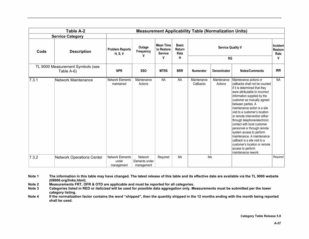
Note 1 The information in this table may have changed. The latest release of this table and its effective date are available via the TL 9000 website (tl9000.org/links.html).
Note 2 Measurements FRT, OFR & OTD are applicable and must be reported for all categories. Note 3 Categories listed in RED or italicized will be used for possible data aggregation only. Measurements must be submitted per the lower
category listing. Note 4 If the normalization factor contains the word “shipped”, then the quantity shipped in the 12 months ending with the month being reported
shall be used. Category Table Release 5.8 A-57
Table A-2 Measurement Applicability Table (Normalization Units) Service Category
Code Description Problem Reports H, S, V
Outage Frequency
V
Mean Time to Restore
Service V
Basic Return Rate
H
Service Quality V
Incident Restore
Rate V SQ
TL 9000 Measurement Symbols (see Table A-6) NPR SSO MTRS BRR Numerator Denominator Notes/Comments
IRR
7.3.1 Network Maintenance Network Elements maintained
Maintenance Actions
NA NA Maintenance Callbacks
Maintenance Actions
Maintenance actions or callbacks shall not be counted if it is determined that they were attributable to incorrect information supplied by the customer as mutually agreed between parties. A maintenance action is a site visit to a customer’s location or remote intervention either through telephone/electronic contact with local customer personnel or through remote system access to perform maintenance. A maintenance callback is a site visit to a customer’s location or remote access to perform maintenance rework.
NA
7.3.2 Network Operations Center Network Elements under
management
Network Elements under
management
Required NA NA Required

Note 1 The information in this table may have changed. The latest release of this table and its effective date are available via the TL 9000 website (tl9000.org/links.html).
Note 2 Measurements FRT, OFR & OTD are applicable and must be reported for all categories. Note 3 Categories listed in RED or italicized will be used for possible data aggregation only. Measurements must be submitted per the lower
category listing. Note 4 If the normalization factor contains the word “shipped”, then the quantity shipped in the 12 months ending with the month being reported
shall be used. Note 5 Unless specified differently in the Table above, the SQ denominator is the total number of service transactions newly opened in the month. Category Table Release 5.8 A-58
Table A-2 Measurement Applicability Table (Normalization Units) Service Category
Code Description Problem Reports H, S, V
Outage Frequency
V
Mean Time to Restore
Service V
Basic Return Rate
H
Service Quality V
Incident Restore
Rate V SQ
TL 9000 Measurement Symbols (see Table A-6) NPR SSO MTRS BRR Numerator Denominator Notes/Comments
IRR
7.3.3 Network Performance Services
Job Job NA NA Defective Tasks Tasks Task = each separately listed item in the statement of work or contract for a given job
NA
7.4 Repair Services Units repaired NA NA NA Units returned in the report month within 12 months
(to the day) of their shipment by the repair organization
Number of units shipped by the repair
organization in the 12 months
prior to the report month
The glossary definition of “return” applies. Returns are counted when received by the organization.
NA
7.5 Customer Support Services
7.5.1 Technical Assistance and Customer Support Centers
Support requests Support requests NA NA Unsatisfactory Support Request
Responses
Support Requests
A customer support service transaction where there was a failure to meet an internal or defined customer requirement regarding a) problem escalation response time, b) problem escalation routing, c) internal and/or external notifications, or
NA

Note 1 The information in this table may have changed. The latest release of this table and its effective date are available via the TL 9000 website (tl9000.org/links.html).
Note 2 Measurements FRT, OFR & OTD are applicable and must be reported for all categories. Note 3 Categories listed in RED or italicized will be used for possible data aggregation only. Measurements must be submitted per the lower
category listing. Note 4 If the normalization factor contains the word “shipped”, then the quantity shipped in the 12 months ending with the month being reported
shall be used. Category Table Release 5.8 A-59
Table A-2 Measurement Applicability Table (Normalization Units) Service Category
Code Description Problem Reports H, S, V
Outage Frequency
V
Mean Time to Restore
Service V
Basic Return Rate
H
Service Quality V
Incident Restore
Rate V SQ
TL 9000 Measurement Symbols (see Table A-6) NPR SSO MTRS BRR Numerator Denominator Notes/Comments
IRR
d) personnel competencies and/or customer communication skills or results in a customer complaint or perceived defect in the support received related to the support center activity including SSO reportable events (not the underlying hardware, software or other product being supported). Customer Support Center activities that become customer originated problem reports are not included in this measure.
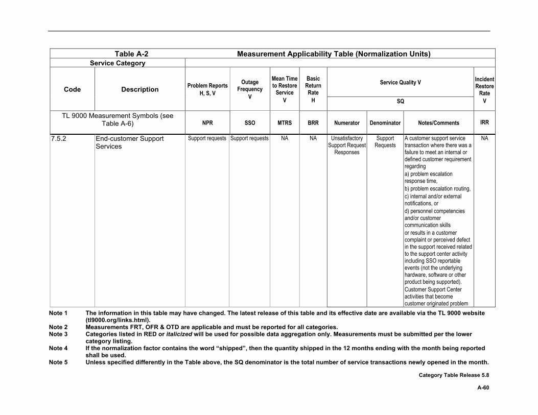
Note 1 The information in this table may have changed. The latest release of this table and its effective date are available via the TL 9000 website (tl9000.org/links.html).
Note 2 Measurements FRT, OFR & OTD are applicable and must be reported for all categories. Note 3 Categories listed in RED or italicized will be used for possible data aggregation only. Measurements must be submitted per the lower
category listing. Note 4 If the normalization factor contains the word “shipped”, then the quantity shipped in the 12 months ending with the month being reported
shall be used. Note 5 Unless specified differently in the Table above, the SQ denominator is the total number of service transactions newly opened in the month. Category Table Release 5.8 A-60
Table A-2 Measurement Applicability Table (Normalization Units) Service Category
Code Description Problem Reports H, S, V
Outage Frequency
V
Mean Time to Restore
Service V
Basic Return Rate
H
Service Quality V
Incident Restore
Rate V SQ
TL 9000 Measurement Symbols (see Table A-6) NPR SSO MTRS BRR Numerator Denominator Notes/Comments
IRR
7.5.2 End-customer Support Services
Support requests Support requests NA NA Unsatisfactory Support Request
Responses
Support Requests
A customer support service transaction where there was a failure to meet an internal or defined customer requirement regarding a) problem escalation response time, b) problem escalation routing, c) internal and/or external notifications, or d) personnel competencies and/or customer communication skills or results in a customer complaint or perceived defect in the support received related to the support center activity including SSO reportable events (not the underlying hardware, software or other product being supported). Customer Support Center activities that become customer originated problem
NA

Note 1 The information in this table may have changed. The latest release of this table and its effective date are available via the TL 9000 website (tl9000.org/links.html).
Note 2 Measurements FRT, OFR & OTD are applicable and must be reported for all categories. Note 3 Categories listed in RED or italicized will be used for possible data aggregation only. Measurements must be submitted per the lower
category listing. Note 4 If the normalization factor contains the word “shipped”, then the quantity shipped in the 12 months ending with the month being reported
shall be used. Category Table Release 5.8 A-61
Table A-2 Measurement Applicability Table (Normalization Units) Service Category
Code Description Problem Reports H, S, V
Outage Frequency
V
Mean Time to Restore
Service V
Basic Return Rate
H
Service Quality V
Incident Restore
Rate V SQ
TL 9000 Measurement Symbols (see Table A-6) NPR SSO MTRS BRR Numerator Denominator Notes/Comments
IRR
reports are not included in this measure.
7.6 Purchasing Services 7.6.1 Procurement Services Unit NA NA NA Units returned in
the report month within 12 months
(to the day) of their
procurement
Number of units procured
in the 12 months prior to
the report month
The glossary definition of “return” applies. Returns are counted when received by the organization.
NA
7.6.2 Sourcing/Purchasing Services
Transactions NA NA NA Defective Transactions
Transactions NA
7.7 Manufacturing Services 7.7.1 Small assemblies Units shipped NA NA Required NA NA 7.7.2 Printed Circuit Board
Assembly Units shipped NA NA Required NA NA
7.7.3 Cable Assembly 7.7.3.1 Metallic Units shipped NA NA Required NA NA 7.7.3.2 Optical Units shipped NA NA Required NA NA 7.7.4 Electromechanical Assembly Units shipped NA NA Required NA NA

Note 1 The information in this table may have changed. The latest release of this table and its effective date are available via the TL 9000 website (tl9000.org/links.html).
Note 2 Measurements FRT, OFR & OTD are applicable and must be reported for all categories. Note 3 Categories listed in RED or italicized will be used for possible data aggregation only. Measurements must be submitted per the lower
category listing. Note 4 If the normalization factor contains the word “shipped”, then the quantity shipped in the 12 months ending with the month being reported
shall be used. Note 5 Unless specified differently in the Table above, the SQ denominator is the total number of service transactions newly opened in the month. Category Table Release 5.8 A-62
Table A-2 Measurement Applicability Table (Normalization Units) Service Category
Code Description Problem Reports H, S, V
Outage Frequency
V
Mean Time to Restore
Service V
Basic Return Rate
H
Service Quality V
Incident Restore
Rate V SQ
TL 9000 Measurement Symbols (see Table A-6) NPR SSO MTRS BRR Numerator Denominator Notes/Comments
IRR
7.7.5 Logistical Services NA 7.7.5.1 Logistical Services, Third
Party Order NA NA NA NA NA
7.7.5.2 Logistical Services, Internal Order NA NA NA NA NA 7.8 Business Services 7.8.1 Not currently used 7.8.2 Contract/Temporary Staffing Position filled NA NA NA Defective
Transactions Transactions NA
7.8.3 Training Courses conducted
NA NA NA Defective Transactions
Courses conducted
NA
7.8.4 Not currently used 7.8.5 Not currently used 7.8.6 Project Management Open projects NA NA NA NA NA 7.9 General Support Services Transaction NA NA NA
Defective
Transactions Transactions NA
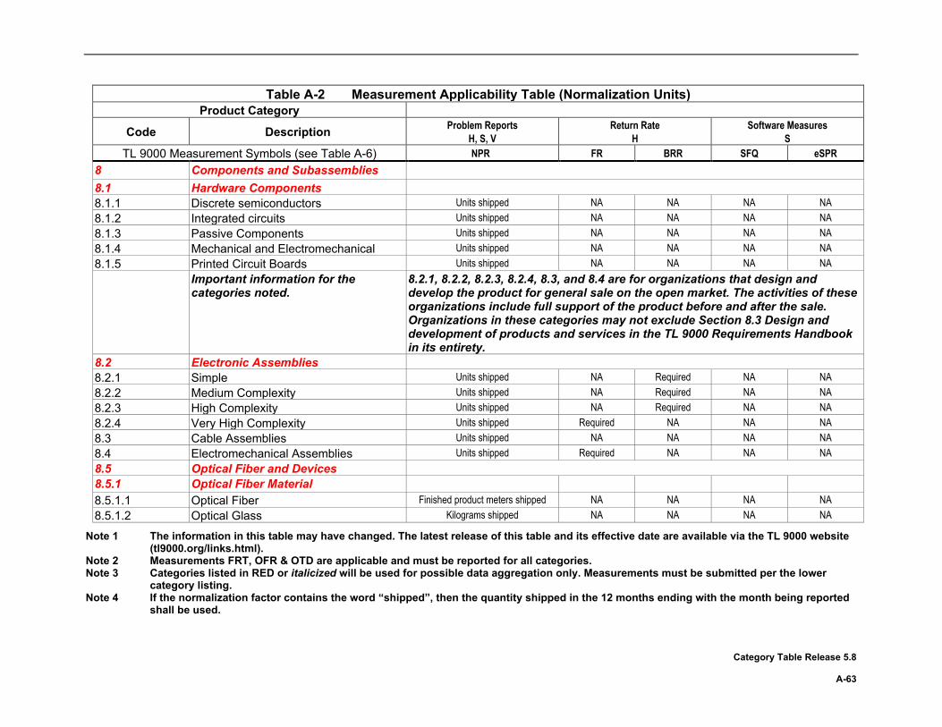
Note 1 The information in this table may have changed. The latest release of this table and its effective date are available via the TL 9000 website (tl9000.org/links.html).
Note 2 Measurements FRT, OFR & OTD are applicable and must be reported for all categories. Note 3 Categories listed in RED or italicized will be used for possible data aggregation only. Measurements must be submitted per the lower
category listing. Note 4 If the normalization factor contains the word “shipped”, then the quantity shipped in the 12 months ending with the month being reported
shall be used. Category Table Release 5.8 A-63
Table A-2 Measurement Applicability Table (Normalization Units) Product Category
Code Description Problem Reports H, S, V
Return Rate H
Software Measures S
TL 9000 Measurement Symbols (see Table A-6) NPR FR BRR SFQ eSPR 8 Components and Subassemblies 8.1 Hardware Components 8.1.1 Discrete semiconductors Units shipped NA NA NA NA 8.1.2 Integrated circuits Units shipped NA NA NA NA 8.1.3 Passive Components Units shipped NA NA NA NA 8.1.4 Mechanical and Electromechanical Units shipped NA NA NA NA 8.1.5 Printed Circuit Boards Units shipped NA NA NA NA Important information for the
categories noted. 8.2.1, 8.2.2, 8.2.3, 8.2.4, 8.3, and 8.4 are for organizations that design and develop the product for general sale on the open market. The activities of these organizations include full support of the product before and after the sale. Organizations in these categories may not exclude Section 8.3 Design and development of products and services in the TL 9000 Requirements Handbook in its entirety.
8.2 Electronic Assemblies 8.2.1 Simple Units shipped NA Required NA NA 8.2.2 Medium Complexity Units shipped NA Required NA NA 8.2.3 High Complexity Units shipped NA Required NA NA 8.2.4 Very High Complexity Units shipped Required NA NA NA 8.3 Cable Assemblies Units shipped NA NA NA NA 8.4 Electromechanical Assemblies Units shipped Required NA NA NA 8.5 Optical Fiber and Devices 8.5.1 Optical Fiber Material 8.5.1.1 Optical Fiber Finished product meters shipped NA NA NA NA 8.5.1.2 Optical Glass Kilograms shipped NA NA NA NA
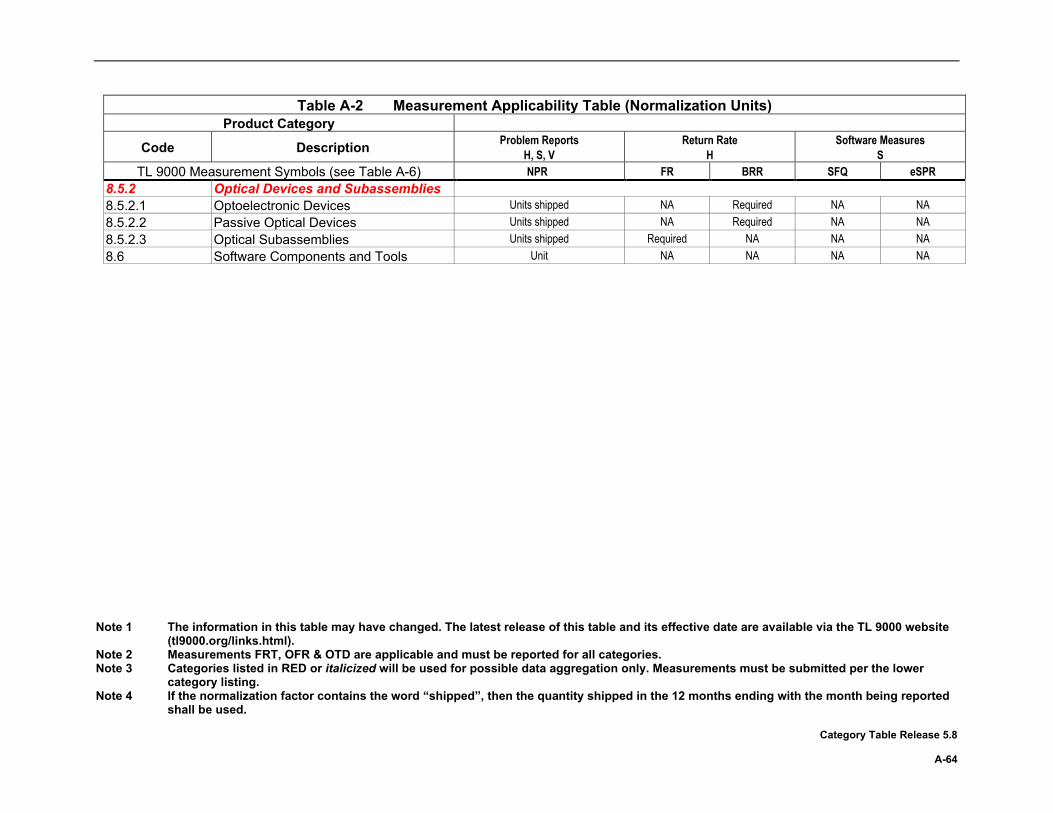
Note 1 The information in this table may have changed. The latest release of this table and its effective date are available via the TL 9000 website (tl9000.org/links.html).
Note 2 Measurements FRT, OFR & OTD are applicable and must be reported for all categories. Note 3 Categories listed in RED or italicized will be used for possible data aggregation only. Measurements must be submitted per the lower
category listing. Note 4 If the normalization factor contains the word “shipped”, then the quantity shipped in the 12 months ending with the month being reported
shall be used. Category Table Release 5.8 A-64
Table A-2 Measurement Applicability Table (Normalization Units) Product Category
Code Description Problem Reports H, S, V
Return Rate H
Software Measures S
TL 9000 Measurement Symbols (see Table A-6) NPR FR BRR SFQ eSPR 8.5.2 Optical Devices and Subassemblies 8.5.2.1 Optoelectronic Devices Units shipped NA Required NA NA 8.5.2.2 Passive Optical Devices Units shipped NA Required NA NA 8.5.2.3 Optical Subassemblies Units shipped Required NA NA NA 8.6 Software Components and Tools Unit NA NA NA NA
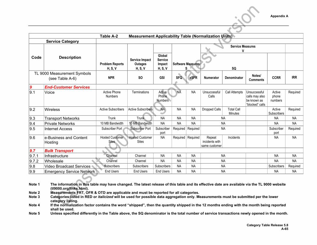
Appendix A
Note 1 The information in this table may have changed. The latest release of this table and its effective date are available via the TL 9000 website (tl9000.org/links.html).
Note 2 Measurements FRT, OFR & OTD are applicable and must be reported for all categories. Note 3 Categories listed in RED or italicized will be used for possible data aggregation only. Measurements must be submitted per the lower
category listing. Note 4 If the normalization factor contains the word “shipped”, then the quantity shipped in the 12 months ending with the month being reported
shall be used. Note 5 Unless specified differently in the Table above, the SQ denominator is the total number of service transactions newly opened in the month.
Category Table Release 5.8 A-65
Table A-2 Measurement Applicability Table (Normalization Units)
Service Category
Code Description Problem Reports
H, S, V
Service Impact Outages H, S, V
Software Measures S
Service Measures V
Global Service Impact H, S, V SQ
TL 9000 Measurement Symbols (see Table A-6) NPR SO GSI SFQ eSPR Numerator Denominator Notes/
Comments CCRR
IRR
9 End-Customer Services 9.1 Voice Active Phone
Numbers Terminations Active
Phone Numbers
NA NA Unsuccessful Calls
Call Attempts Unsuccessful calls may also be known as “blocked” calls
Active phone
numbers
Required
9.2 Wireless Active Subscribers Active Subscribers NA NA NA Dropped Calls Total Call Minutes
Active Subscribers
Required
9.3 Transport Networks Trunk Trunk NA NA NA NA NA NA 9.4 Private Networks 10 MB Bandwidth 10 MB Bandwidth NA NA NA NA NA NA 9.5 Internet Access Subscriber Port Subscriber Port Subscriber
port Required Required NA Subscriber
port Required
9.6 e-Business and Content Hosting
Hosted Customer Sites
Hosted Customer Sites
NA Required Required Repeat incidents with
same customer
Incidents NA NA
9.7 Bulk Transport 9.7.1 Infrastructure Channel Channel NA NA NA NA NA NA 9.7.2 Wholesale Channel Channel NA NA NA NA NA NA 9.8 Video Broadcast Services Subscribers Subscribers Subscribers NA NA NA Subscribers Required 9.9 Emergency Service Network End Users End Users End Users NA NA NA NA NA

Note 1 The information in this table may have changed. The latest release of this table and its effective date are available via the TL 9000 website (tl9000.org/links.html).
Note 2 Measurements FRT, OFR & OTD are applicable and must be reported for all categories. Note 3 Categories listed in RED or italicized will be used for possible data aggregation only. Measurements must be submitted per the lower
category listing. Note 4 If the normalization factor contains the word “shipped”, then the quantity shipped in the 12 months ending with the month being reported
shall be used. Note 5 Unless specified differently in the Table above, the SQ denominator is the total number of service transactions newly opened in the month. Category Table Release 5.3 A-66
This page intentionally left blank
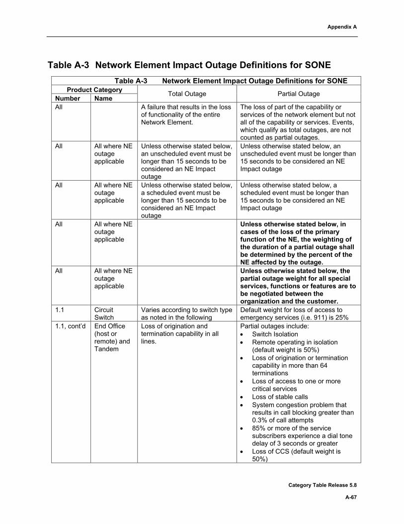
Appendix A
Category Table Release 5.8 A-67
Table A-3 Network Element Impact Outage Definitions for SONE
Table A-3 Network Element Impact Outage Definitions for SONE Product Category Total Outage Partial Outage Number Name
All A failure that results in the loss of functionality of the entire Network Element.
The loss of part of the capability or services of the network element but not all of the capability or services. Events, which qualify as total outages, are not counted as partial outages.
All All where NE outage applicable
Unless otherwise stated below, an unscheduled event must be longer than 15 seconds to be considered an NE Impact outage
Unless otherwise stated below, an unscheduled event must be longer than 15 seconds to be considered an NE Impact outage
All All where NE outage applicable
Unless otherwise stated below, a scheduled event must be longer than 15 seconds to be considered an NE Impact outage
Unless otherwise stated below, a scheduled event must be longer than 15 seconds to be considered an NE Impact outage
All All where NE outage applicable
Unless otherwise stated below, in cases of the loss of the primary function of the NE, the weighting of the duration of a partial outage shall be determined by the percent of the NE affected by the outage.
All All where NE outage applicable
Unless otherwise stated below, the partial outage weight for all special services, functions or features are to be negotiated between the organization and the customer.
1.1 Circuit Switch
Varies according to switch type as noted in the following
Default weight for loss of access to emergency services (i.e. 911) is 25%
1.1, cont’d End Office (host or remote) and Tandem
Loss of origination and termination capability in all lines.
Partial outages include: • Switch Isolation • Remote operating in isolation
(default weight is 50%) • Loss of origination or termination
capability in more than 64 terminations
• Loss of access to one or more critical services
• Loss of stable calls • System congestion problem that
results in call blocking greater than 0.3% of call attempts
• 85% or more of the service subscribers experience a dial tone delay of 3 seconds or greater
• Loss of CCS (default weight is 50%)

Appendix A
Category Table Release 5.8 A-68
Table A-3 Network Element Impact Outage Definitions for SONE Product Category Total Outage Partial Outage Number Name
1.1, cont’d Combined Tandem/ End Office
Loss of origination and termination capability in all terminations.
Same as End Office
1.1, cont’d Hybrid Voice Over Packet (HVOP)
Loss of capability to originate and terminate all traffic.
Partial TDM outage – same as End office above Partial Packet outage - • Loss of an aggregate service
bandwidth over 5% of the provisioned bandwidth for more than 10 seconds
• Interface switchovers that last longer than 60 milliseconds
• Loss of access to one or more critical services
• System congestion problem that results in call blocking greater than 0.3% of call attempts
• Loss of stable connections • Total loss of a non-critical service • Total loss of one or more
Operation, Administration, & Maintenance (OA&M) functions (default weight is 5%)
• Total loss of visibility from the Element Management System (EMS) (default weight is 10%)
1.1, cont’d MSC/ISC Loss of all capacity for origination and/or termination of voice and data traffic.
• Loss of greater than 5% of the provisioned capacity for origination and/or termination of combined voice and/or data traffic.
• Loss of access to one or more critical services
• Loss of stable connections • Total loss of a non-critical service • Total loss of one or more OA&M
functions (default weight is 5%) • Total loss of visibility from the
Element Management System (EMS) (default weight is 10%)

Appendix A
Category Table Release 5.8 A-69
Table A-3 Network Element Impact Outage Definitions for SONE Product Category Total Outage Partial Outage Number Name
1.2.2.1 Wireline Access Multi-service
Total network element outage is constituted by any of the following events: • Loss of all ability to
transport packets between all interface points including loss of stable connections for a period longer than one second
• Total network element isolation for more than 10 seconds
• Loss of all services for longer than 10 seconds
• For a connection-based network element, total loss of ability to set up or tear down connections for a period longer than 10 seconds.
• Loss of capability to originate and terminate more than 64 lines or trunks (DS0)
• Loss of an aggregate service bandwidth over 5% of the equipped bandwidth for more than 10 seconds or loss of more than 4MB of service bandwidth for more than 5 minutes
• System congestion problem that results in call blocking greater than 0.3% of call attempts
• System congestion which impacts greater than 5% of all session set-up attempts
• Loss of all stable calls or sessions • 85% or more of the service
subscribers experience a session delay of 3 seconds or greater for a period longer than 30 seconds
• Interface switchovers lasting longer than 60 milliseconds
• Total loss of one or more but not all services (such as ISDN capability, DS1, POTS, etc.) for more than 10 seconds
• Total loss of one or more OA&M functions (default weight is 5%)
• Total loss of visibility from Element Management System (EMS) (default weight is 10%)
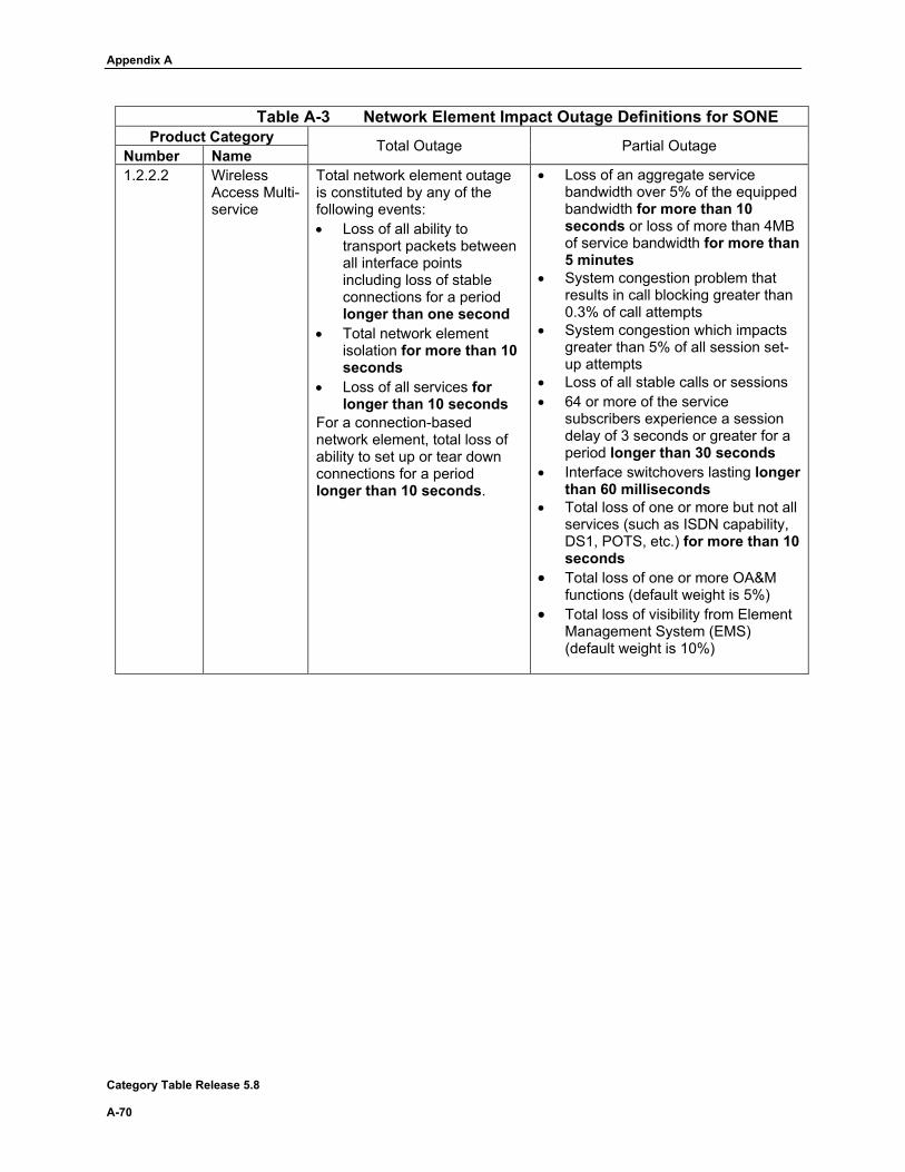
Appendix A
Category Table Release 5.8 A-70
Table A-3 Network Element Impact Outage Definitions for SONE Product Category Total Outage Partial Outage Number Name
1.2.2.2 Wireless Access Multi-service
Total network element outage is constituted by any of the following events: • Loss of all ability to
transport packets between all interface points including loss of stable connections for a period longer than one second
• Total network element isolation for more than 10 seconds
• Loss of all services for longer than 10 seconds
For a connection-based network element, total loss of ability to set up or tear down connections for a period longer than 10 seconds.
• Loss of an aggregate service bandwidth over 5% of the equipped bandwidth for more than 10 seconds or loss of more than 4MB of service bandwidth for more than 5 minutes
• System congestion problem that results in call blocking greater than 0.3% of call attempts
• System congestion which impacts greater than 5% of all session set-up attempts
• Loss of all stable calls or sessions • 64 or more of the service
subscribers experience a session delay of 3 seconds or greater for a period longer than 30 seconds
• Interface switchovers lasting longer than 60 milliseconds
• Total loss of one or more but not all services (such as ISDN capability, DS1, POTS, etc.) for more than 10 seconds
• Total loss of one or more OA&M functions (default weight is 5%)
• Total loss of visibility from Element Management System (EMS) (default weight is 10%)

Appendix A
Category Table Release 5.8 A-71
Table A-3 Network Element Impact Outage Definitions for SONE Product Category Total Outage Partial Outage Number Name
1.2.2.3 Virtualized (Multi-service)
Total network element outage is constituted by any of the following events: • Loss of all ability to
transport packets between all interface points including loss of stable connections for a period longer than one second
• Total network element isolation for more than 10 seconds
• Loss of all services for longer than 10 seconds
For a connection-based network element, total loss of ability to set up or tear down connections for a period longer than 10 seconds.
• Loss of an aggregate service bandwidth over 5% of the equipped bandwidth for more than 10 seconds or loss of more than 4MB of service bandwidth for more than 5 minutes
• System congestion problem that results in call blocking greater than 0.3% of call attempts
• System congestion which impacts greater than 5% of all session set-up attempts
• Loss of all stable calls or sessions • 64 or more of the service
subscribers experience a session delay of 3 seconds or greater for a period longer than 30 seconds
• Interface switchovers lasting longer than 60 milliseconds
• Total loss of one or more but not all services (such as ISDN capability, DS1, POTS, etc.) for more than 10 seconds
• Total loss of one or more OA&M functions (default weight is 5%)
• Total loss of visibility from Element Management System (EMS) (default weight is 10%)
1.2.3 Media Gateways
Total loss of ability to provide multimedia communications across networks for more than 5 seconds
• Loss of more than 5% of multimedia services for more than 5 seconds
• Loss of stable service sessions • Total loss of one or more but not all
services for more than 5 seconds • System congestion which impacts
greater than 5% of all session set-up attempts
• 85% or more of the service subscribers experience a session delay of 3 seconds or greater for a period longer than 30 seconds
• Interface switchovers lasting longer than 60 milliseconds
• Total loss of one or more OA&M functions (default weight is 5%)
• Total loss of visibility from Element Management System (EMS) (default weight is 10%)
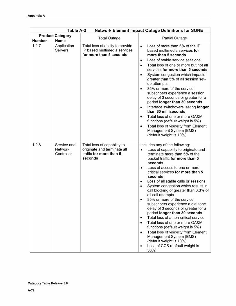
Appendix A
Category Table Release 5.8 A-72
Table A-3 Network Element Impact Outage Definitions for SONE Product Category Total Outage Partial Outage Number Name
1.2.7 Application Servers
Total loss of ability to provide IP based multimedia services for more than 5 seconds
• Loss of more than 5% of the IP based multimedia services for more than 5 seconds
• Loss of stable service sessions • Total loss of one or more but not all
services for more than 5 seconds • System congestion which impacts
greater than 5% of all session set-up attempts
• 85% or more of the service subscribers experience a session delay of 3 seconds or greater for a period longer than 30 seconds
• Interface switchovers lasting longer than 60 milliseconds
• Total loss of one or more OA&M functions (default weight is 5%)
• Total loss of visibility from Element Management System (EMS) (default weight is 10%)
1.2.8 Service and
Network Controller
Total loss of capability to originate and terminate all traffic for more than 5 seconds
Includes any of the following: • Loss of capability to originate and
terminate more than 5% of the packet traffic for more than 5 seconds
• Loss of access to one or more critical services for more than 5 seconds
• Loss of all stable calls or sessions • System congestion which results in
call blocking of greater than 0.3% of all call attempts
• 85% or more of the service subscribers experience a dial tone delay of 3 seconds or greater for a period longer than 30 seconds
• Total loss of a non-critical service • Total loss of one or more OA&M
functions (default weight is 5%) • Total loss of visibility from Element
Management System (EMS) (default weight is 10%)
• Loss of CCS (default weight is 50%)

Appendix A
Category Table Release 5.8 A-73
Table A-3 Network Element Impact Outage Definitions for SONE Product Category Total Outage Partial Outage Number Name
1.2.9.1.1 Legacy Core Routers
Total network element outage is constituted by any of the following events: • Loss of all ability to
transport packets between all interface points including loss of stable connections for a period longer than one second
• Total network element isolation for more than 10 seconds
• Loss of all services for longer than 10 seconds
For a connection-based network element, total loss of ability to set up or tear down connections for a period longer than 10 seconds.
• Loss of an aggregate service bandwidth over 5% of the equipped bandwidth for more than 10 seconds or loss of more than 4MB of service bandwidth for more than 5 minutes
• Interface switchovers lasting longer than 60 milliseconds
• Total loss of a service(s) for more than 10 seconds
• Total loss of one or more OA&M functions (default weight is 5%)
• Total loss of visibility from Element Management System (EMS) (default weight is 10%)
1.2.9.1.2 Virtualized Core Routers
Total network element outage is constituted by any of the following events: • Loss of all ability to
transport packets between all interface points including loss of stable connections for a period longer than one second
• Total network element isolation for more than 10 seconds
• Loss of all services for longer than 10 seconds
For a connection-based network element, total loss of ability to set up or tear down connections for a period longer than 10 seconds.
• Loss of an aggregate service bandwidth over 5% of the equipped bandwidth for more than 10 seconds or loss of more than 4MB of service bandwidth for more than 5 minutes
• Interface switchovers lasting longer than 60 milliseconds
• Total loss of a service(s) for more than 10 seconds
• Total loss of one or more OA&M functions (default weight is 5%)
• Total loss of visibility from Element Management System (EMS) (default weight is 10%)

Appendix A
Category Table Release 5.8 A-74
Table A-3 Network Element Impact Outage Definitions for SONE Product Category Total Outage Partial Outage Number Name
1.2.9.2.1 Legacy Edge Routers
Total network element outage is constituted by any of the following events: • Loss of all ability to
transport packets between all interface points including loss of stable connections for a period longer than one second
• Total network element isolation for more than 10 seconds
• Loss of all services for longer than 10 seconds
For a connection-based network element, total loss of ability to set up or tear down connections for a period longer than 10 seconds.
• Loss of an aggregate service bandwidth over 5% of the equipped bandwidth for more than 10 seconds or loss of more than 4MB of service bandwidth for more than 5 minutes
• Interface switchovers lasting longer than 60 milliseconds
• Total loss of a service(s) for more than 10 seconds
• Total loss of one or more OA&M functions (default weight is 5%)
• Total loss of visibility from Element Management System (EMS) (default weight is 10%)
1.2.9.2.2 Virtualized Edge Routers
Total network element outage is constituted by any of the following events: • Loss of all ability to
transport packets between all interface points including loss of stable connections for a period longer than one second
• Total network element isolation for more than 10 seconds
• Loss of all services for longer than 10 seconds
For a connection-based network element, total loss of ability to set up or tear down connections for a period longer than 10 seconds.
• Loss of an aggregate service bandwidth over 5% of the equipped bandwidth for more than 10 seconds or loss of more than 4MB of service bandwidth for more than 5 minutes
• Interface switchovers lasting longer than 60 milliseconds
• Total loss of a service(s) for more than 10 seconds
• Total loss of one or more OA&M functions (default weight is 5%)
• Total loss of visibility from Element Management System (EMS) (default weight is 10%)
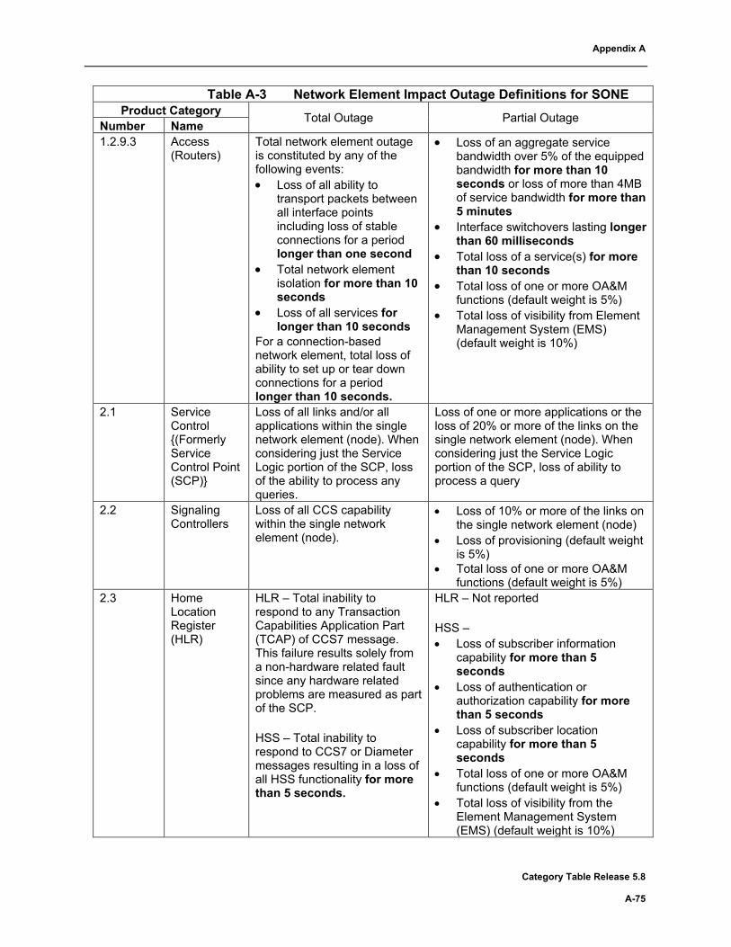
Appendix A
Category Table Release 5.8 A-75
Table A-3 Network Element Impact Outage Definitions for SONE Product Category Total Outage Partial Outage Number Name
1.2.9.3 Access (Routers)
Total network element outage is constituted by any of the following events: • Loss of all ability to
transport packets between all interface points including loss of stable connections for a period longer than one second
• Total network element isolation for more than 10 seconds
• Loss of all services for longer than 10 seconds
For a connection-based network element, total loss of ability to set up or tear down connections for a period longer than 10 seconds.
• Loss of an aggregate service bandwidth over 5% of the equipped bandwidth for more than 10 seconds or loss of more than 4MB of service bandwidth for more than 5 minutes
• Interface switchovers lasting longer than 60 milliseconds
• Total loss of a service(s) for more than 10 seconds
• Total loss of one or more OA&M functions (default weight is 5%)
• Total loss of visibility from Element Management System (EMS) (default weight is 10%)
2.1 Service Control {(Formerly Service Control Point (SCP)}
Loss of all links and/or all applications within the single network element (node). When considering just the Service Logic portion of the SCP, loss of the ability to process any queries.
Loss of one or more applications or the loss of 20% or more of the links on the single network element (node). When considering just the Service Logic portion of the SCP, loss of ability to process a query
2.2 Signaling Controllers
Loss of all CCS capability within the single network element (node).
• Loss of 10% or more of the links on the single network element (node)
• Loss of provisioning (default weight is 5%)
• Total loss of one or more OA&M functions (default weight is 5%)
2.3 Home Location Register (HLR)
HLR – Total inability to respond to any Transaction Capabilities Application Part (TCAP) of CCS7 message. This failure results solely from a non-hardware related fault since any hardware related problems are measured as part of the SCP. HSS – Total inability to respond to CCS7 or Diameter messages resulting in a loss of all HSS functionality for more than 5 seconds.
HLR – Not reported HSS – • Loss of subscriber information
capability for more than 5 seconds
• Loss of authentication or authorization capability for more than 5 seconds
• Loss of subscriber location capability for more than 5 seconds
• Total loss of one or more OA&M functions (default weight is 5%)
• Total loss of visibility from the Element Management System (EMS) (default weight is 10%)
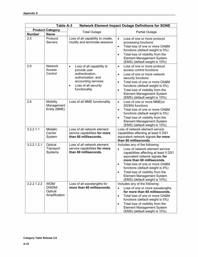
Appendix A
Category Table Release 5.8 A-76
Table A-3 Network Element Impact Outage Definitions for SONE Product Category Total Outage Partial Outage Number Name
2.5 Protocol Servers
Loss of all capability to create, modify and terminate sessions
• Loss of one or more protocol processing functions
• Total loss of one or more OA&M functions (default weight is 5%)
• Total loss of visibility from the Element Management System (EMS) (default weight is 10%)
2.6 Network Access Control
• Loss of all capability to provide user authentication, authorization, and accounting services
• Loss of all security functionality
• Loss of one or more protocol access control functions
• Loss of one or more network security functions
• Total loss of one or more OA&M functions (default weight is 5%)
• Total loss of visibility from the Element Management System (EMS) (default weight is 10%)
2.8 Mobility Management Entity (MME)
Loss of all MME functionality • Loss of one or more MME(or SGSN) functions
• Total loss of one or more OA&M functions (default weight is 5%)
• Total loss of visibility from the Element Management System (EMS) (default weight is 10%)
3.2.2.1.1 Metallic Carrier System
Loss of all network element service capabilities for more than 60 milliseconds.
Loss of network element service capabilities affecting at least 5 DS1 equivalent network signals for more than 60 milliseconds.
3.2.2.1.2.1 Optical Transport Systems
Loss of all network element service capabilities for more than 60 milliseconds.
Includes any of the following: • Loss of network element service
capabilities affecting at least 5 DS1 equivalent network signals for more than 60 milliseconds.
• Total loss of one or more OA&M functions (default weight is 5%)
• Total loss of visibility from the Element Management System (EMS) (default weight is 10%)
3.2.2.1.2.2 WDM/ DWDM/ Optical Amplification
Loss of all wavelengths for more than 60 milliseconds.
Includes any of the following: • Loss of one or more wavelengths
for more than 60 milliseconds. • Total loss of one or more OA&M
functions (default weight is 5%) • Total loss of visibility from the
Element Management System (EMS) (default weight is 10%)

Appendix A
Category Table Release 5.8 A-77
Table A-3 Network Element Impact Outage Definitions for SONE Product Category Total Outage Partial Outage Number Name
3.2.2.1.2.3 Reconfigur-able Optical Add-Drop Multiplexer (ROADM)
Loss of all network element service capabilities for more than 60 milliseconds.
Includes any of the following: • Loss of network element service
capabilities affecting at least 5 DS1 equivalent network signals for more than 60 milliseconds.
• Loss of one or more wavelengths for more than 60 milliseconds.
• Total loss of one or more OA&M functions (default weight is 5%)
• Total loss of visibility from the Element Management System (EMS) (default weight is 10%)
3.2.2.1.3 Microwave Loss of all network element service capabilities for more than 60 milliseconds.
Loss of network element service capabilities affecting at least 5 DS1 equivalent network signals for more than 60 milliseconds.
3.2.2.2 Loop Carrier Loss of all network element service capabilities for more than 60 milliseconds.
Includes any of the following: • Loss of 3 or more DS1 equivalents
for more than 60 milliseconds • Loss of 72 or more subscriber lines • Total loss of one or more OA&M
functions (default weight is 5%) • Total loss of visibility from the
Element Management System (EMS) (default weight is 10%)
3.2.4 Digital Subscriber Line (DSL)
Loss of capability to provide connectivity for all traffic for more than 10 seconds or total NE isolation for more than 10 seconds
Loss of capability to provide connectivity for16 subscribers for a period longer than 10 seconds
3.2.5 Fiber to the User
Loss of capability to provide connectivity for all traffic for more than 10 seconds or total NE isolation for more than 10 seconds
Loss of capability to provide connectivity for 16 subscribers for a period longer than 10 seconds
3.3.1 Base Station Controller Equipment
Total loss of voice and data traffic capability
Loss of greater than 5% of the provisioned capacity for origination and/or termination of voice and/or data traffic.
3.3.2.1 Basic Base Transceiver System (BTS)
Total loss of voice and data traffic capability
Loss of greater than 5% of the provisioned capacity for origination and/or termination of voice and/or data traffic.
3.3.2.2 Advanced Base Transceiver System (BTS)
Total loss of voice and data traffic capability
Loss of greater than 5% of the provisioned capacity for origination and/or termination of voice and/or data traffic.

Appendix A
Category Table Release 5.8 A-78
Table A-3 Network Element Impact Outage Definitions for SONE Product Category Total Outage Partial Outage Number Name
3.3.2.3 4G Base Transceiver System (BTS)
Total loss of voice and data traffic capability
Loss of greater than 5% of the provisioned capacity for origination and/or termination of voice and/or data traffic.
3.3.2.4 Small Cell Radios
Total loss of voice and data traffic capability
Loss of greater than 5% of the provisioned capacity for origination and/or termination of voice and/or data traffic.
3.3.2.5 Combined Total loss of voice and data traffic capability
Loss of greater than 5% of the provisioned capacity for origination and/or termination of voice and/or data traffic. Minimum outage impact for loss of 5G capability (5%), 4G capability (5%), 3G capability (30%) or 2G capability (5%) or per agreed SLA with customer.
3.3.2.6 5G Total loss of voice and data traffic capability
Loss of greater than 5% of the provisioned capacity for origination and/or termination of voice and/or data traffic.
3.3.4 WLAN Base Station Equipment
Total loss of an Access Point (AP) or Network Access Point (NAP)
Loss of greater than 10% of the provisioned capacity for origination and/or termination of voice and/or data traffic.
3.3.5.1 Remote Radio Unit (RRU)
Total loss of voice and data traffic capability
Loss of greater than 5% of the provisioned capacity for origination and/or termination of voice and/or data traffic.
3.3.5.2 Virtualized Baseband Unit (BBU)
Total loss of ability to process and/or transport the baseband signal
Loss of greater than 5% of the provisioned capacity to process or transport the baseband signal.
3.3.5.3 Virtualized Central Unit (CU)
Total loss of all functionality Loss of greater than 5% of the provisioned capacity
3.3.5.4 Virtualized Control Plane (CUCP)
Total loss of all functionality Loss of greater than 5% of the provisioned capacity
3.3.5.5 Virtualized User Plane (CUUP)
Total loss of all functionality Loss of greater than 5% of the provisioned capacity
3.3.5.6 Virtualized Distribution Unit (DU)
Total loss of all functionality Loss of greater than 5% of the provisioned capacity

Appendix A
Category Table Release 5.8 A-79
Table A-3 Network Element Impact Outage Definitions for SONE Product Category Total Outage Partial Outage Number Name
3.4.1 Location Services
Total loss of ability to provide location-based services
• Loss of more than 5% of the of the location-based services
• Loss of all stable service sessions • Total loss of one or more services
but not all services for more than 10 seconds
• System congestion which impacts greater than 5% of all session set-up attempts
• 85% or more of the service subscribers experience a session delay of 3 seconds or greater for a period longer than 30 seconds
• Interface switchovers lasting longer than 60 milliseconds
• Loss of one of more OA& M functions (default weight is 5%)
• Total loss of visibility from the Element Management System (EMS) (default weight is 10%)
4.2.1.1 Legacy On-Line Critical
Complete loss of all FCAPS (Fault Configuration Accounting Performance Security) functionality for more than 1 minute.
Loss of some FCAPS functionality for more than 1 minute. Partial outage time is weighted by % of users impacted and by amount of functionality lost by the outage.
4.2.1.2 NFV Orchestrator
Complete loss of all functionality for more than 1 minute.
Loss of some functionality for more than 1 minute. Partial outage time is weighted by % of users impacted and by amount of functionality lost by the outage.
4.2.2.1 Legacy On-Line Non-Critical
Complete loss of all FCAPS (Fault Configuration Accounting Performance Security) functionality for more than 1 minute.
Loss of some FCAPS functionality for more than 1 minute. Partial outage time is weighted by % of users impacted and by amount of functionality lost by the outage.
4.2.2.2 Virtual Network Function Manager
Complete loss of all functionality for more than 1 minute.
Loss of some functionality for more than 1 minute. Partial outage time is weighted by % of users impacted and by amount of functionality lost by the outage.
4.2.3 Off-line Complete loss of all FCAPS (Fault Configuration Accounting Performance Security) functionality for more than 1 minute.
Loss of some FCAPS functionality for more than 1 minute. Partial outage time is weighted by % of users impacted and by amount of functionality lost by the outage.
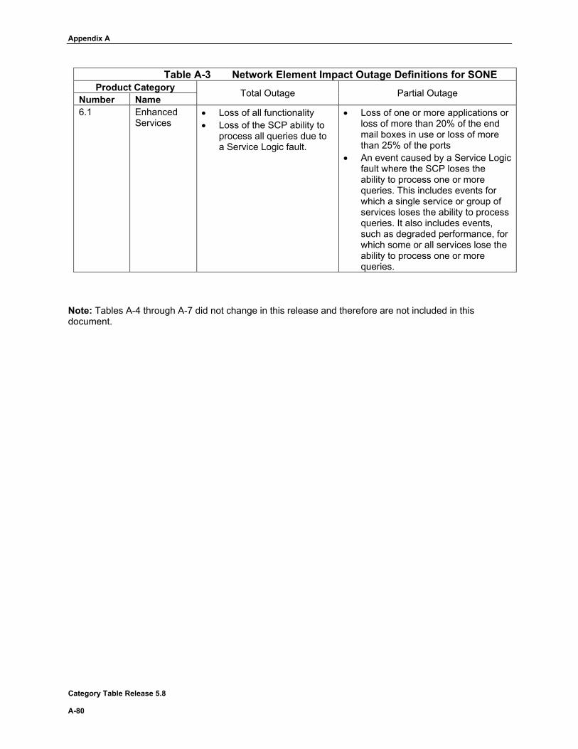
Appendix A
Category Table Release 5.8 A-80
Table A-3 Network Element Impact Outage Definitions for SONE Product Category Total Outage Partial Outage Number Name
6.1 Enhanced Services
• Loss of all functionality • Loss of the SCP ability to
process all queries due to a Service Logic fault.
• Loss of one or more applications or loss of more than 20% of the end mail boxes in use or loss of more than 25% of the ports
• An event caused by a Service Logic fault where the SCP loses the ability to process one or more queries. This includes events for which a single service or group of services loses the ability to process queries. It also includes events, such as degraded performance, for which some or all services lose the ability to process one or more queries.
Note: Tables A-4 through A-7 did not change in this release and therefore are not included in this document.