appendix 15.2 phase 1b (north): generic quantitative … report is confidential to the client and we...
TRANSCRIPT

Volume 3: Environmental Statement Further Information Report Appendices Brent Cross Cricklewood: Phase 1B (North) FIR
N:\Projects\WIE11453\100\8_Reports\2. ES\Volume 3 - Appendices\Volume 3 ES Further Information Report Appendices - Front Cover_2.docx
Appendix 15.2 Phase 1B (North): Generic Quantitative Geo-Environmental
Assessment

Generic Quantitative Geo-Environmental Assessment Phase 1BN Brent Cross, Cricklewood, London
February 2017
Waterman Infrastructure & Environment Limited Pickfords Wharf, Clink Street, London, SE1 9DG www.watermangroup.com


1.1.4 Updated with results of all ground gas and vapour monitoring.
Client Name: Hammerson & Standard Life Investment Ltd Document Reference: WIC15997-100-R-1.1.4-GQRA Project Number: WIE15997
Quality Assurance – Approval Status This document has been prepared and checked in accordance with Waterman Group’s IMS (BS EN ISO 9001: 2008, BS EN ISO 14001: 2004 and BS OHSAS 18001:2007)
Issue Date Prepared by Checked by Approved by 1.1.4 February 2017 Robbie Moore John Coates Carl Slater
Marion Duff Chris Gell
Carl Slater
Comments

Disclaimer
This report has been prepared by Waterman Infrastructure & Environment Limited, with all reasonable skill, care and diligence within the terms of the Contract with the client, incorporation of our General Terms and Condition of Business and taking account of the resources devoted to us by agreement with the client.
We disclaim any responsibility to the client and others in respect of any matters outside the scope of the above.
This report is confidential to the client and we accept no responsibility of whatsoever nature to third parties to whom this report, or any part thereof, is made known. Any such party relies on the report at its own risk.

Generic Quantitative Geo-Environmental Assessment Contents
\\S-lncs\wtdl\Projects\CIV15997 Brent Cross\DOCUMENTS\CATEGORY\GT\1. Generic Quantitative Geotechnical and Geoenvironmental Risk Assessment\WIC15997-100-R-1.1.4-GQRA.docx
Contents Executive Summary
1. Introduction ................................................................................................................................. 11.1 Objectives ........................................................................................................................ 1 1.2 Proposed Development ................................................................................................... 1 1.3 Regulatory Context .......................................................................................................... 2 1.4 Constraints ....................................................................................................................... 4
2. Procedures .................................................................................................................................. 6
3. Outline Conceptual Model ......................................................................................................... 73.1 Ground Conditions ........................................................................................................... 7 3.2 Potentially Significant Pollution Linkages ........................................................................ 8
4. Rationale and Specific Objectives .......................................................................................... 11
5. Methodology ............................................................................................................................. 125.1 Design of Investigation ................................................................................................... 12 5.2 Quality Control ............................................................................................................... 13 5.3 Health and Safety........................................................................................................... 14
6. Site Activities ............................................................................................................................ 156.1 Services and Drainage Survey ...................................................................................... 15 6.2 Soil Sampling ................................................................................................................. 16 6.3 Installations .................................................................................................................... 16 6.4 Groundwater Monitoring ................................................................................................ 17 6.5 Ground Gas and Vapour Monitoring .............................................................................. 17
7. Ground Conditions and Material Properties .......................................................................... 197.1 Geological Strata ............................................................................................................ 19 7.2 Made Ground ................................................................................................................. 20 7.3 Alluvium .......................................................................................................................... 23 7.4 Taplow Gravel Formation ............................................................................................... 26 7.5 London Clay Formation .................................................................................................. 27 7.6 Reading Formation (Upper Lambeth Group) ................................................................. 29 7.7 Upnor Formation (Lower Lambeth Group) ..................................................................... 31 7.8 Thanet Formation ........................................................................................................... 32 7.9 Chalk Group ................................................................................................................... 33 7.10 Aggressive Chemical Environment for Concrete Classification ..................................... 34 7.11 Groundwater, Permeability and Soils Infiltration ............................................................ 35 7.11.1 Groundwater ..................................................................................................................35 7.11.2 Permeability ...................................................................................................................35 7.11.3 Soil Infiltration .................................................................................................................35

Generic Quantitative Geo-Environmental Assessment Contents
\\S-lncs\wtdl\Projects\CIV15997 Brent Cross\DOCUMENTS\CATEGORY\GT\1. Generic Quantitative Geotechnical and Geoenvironmental Risk Assessment\WIC15997-100-R-1.1.4-GQRA.docx
8. Environmental Results ............................................................................................................. 368.1 Chemical Analysis .......................................................................................................... 36 8.2 Controlled Waters .......................................................................................................... 36 8.2.1 Shallow Groundwater (Made Ground, Alluvium and Taplow Gravel Formation) ...........36 8.2.2 Deep Groundwater (Lambeth Group) ............................................................................36 8.3 Ground Gas and Vapours .............................................................................................. 37 8.3.1 Soil Consultants Monitoring ...........................................................................................37 8.3.2 Structural Soils Monitoring .............................................................................................38
9. Generic Assessment Criteria .................................................................................................. 40
10. Quantitative Environmental Risk Assessment ...................................................................... 4110.1 Risk to Human Health .................................................................................................... 42 10.1.1 Brent Cross Shopping Centre Expansion ......................................................................42 10.1.2 River Brent Infilling Works ..............................................................................................45 10.1.3 Sturgess Park .................................................................................................................45 10.1.4 Plot 113 ..........................................................................................................................46 10.2 Risk to Controlled Waters .............................................................................................. 46 10.3 Risk posed by Ground Gas and Vapours ...................................................................... 48 10.3.1 Ground Gas ....................................................................................................................48 10.3.2 Vapours ..........................................................................................................................49 10.4 Risks to Construction Workers from Ground Contamination ......................................... 50 10.5 Risk to Ecological Systems/Vegetation.......................................................................... 50 10.6 Risk to Water Supply Pipes ........................................................................................... 50
11. Geotechnical Assessment ....................................................................................................... 5111.1 Proposed Development Structures ................................................................................ 51 11.2 Characteristic Values and Design Bearing Resistance ................................................. 51 11.2.1 Shallow Foundations ......................................................................................................52 11.2.2 Piled Foundations ..........................................................................................................52 11.2.3 Floor Slabs .....................................................................................................................54 11.2.4 Basements .....................................................................................................................54 11.2.5 Shrinkability / Volume Change Potential ........................................................................55 11.2.6 Design Class for Concrete .............................................................................................55 11.2.7 Groundwater / Stability of Excavations ..........................................................................55 11.2.8 Pavement Design ...........................................................................................................56 11.2.9 Material Reusability ........................................................................................................56
12. Preliminary Waste Classification Assessment ...................................................................... 5812.1 Introduction .................................................................................................................... 58

Generic Quantitative Geo-Environmental Assessment Contents
\\S-lncs\wtdl\Projects\CIV15997 Brent Cross\DOCUMENTS\CATEGORY\GT\1. Generic Quantitative Geotechnical and Geoenvironmental Risk Assessment\WIC15997-100-R-1.1.4-GQRA.docx
12.2 Hazardous Property Assessment .................................................................................. 58 12.3 Waste Acceptance Criteria ............................................................................................ 60 12.4 Preliminary Waste Classification Assessment Summary .............................................. 62 12.5 Potential for re-use of waste arisings on-Site ................................................................ 63 12.6 Disposal of waste arisings off-Site ................................................................................. 63
13. Conclusions .............................................................................................................................. 6513.1 Environmental Conclusions and Recommendations ..................................................... 65 13.2 Geotechnical Conclusions and Recommendations ....................................................... 70
Tables Table 1: Geology and hydrogeology encountered during previous ground investigations ............ 7 Table 2: Potentially Significant Pollution Linkages ........................................................................ 8 Table 3: Ground investigation strategy ........................................................................................ 12 Table 4: Summary of fieldwork activities ...................................................................................... 15 Table 5: Installed monitoring wells and target strata ................................................................... 16 Table 6: Ground Summary ........................................................................................................... 19 Table 7: Made Ground – Summary of Geotechnical Test Results .............................................. 22 Table 8: Alluvium – Summary of Geotechnical Test Results ....................................................... 25 Table 9: Taplow Gravel Formation – Summary of Geotechnical Test Results ............................ 26 Table 10: London Clay Formation– Summary of Geotechnical Test Results ................................ 28 Table 11: Reading Formation – Summary of Geotechnical Test Results ...................................... 30 Table 12: Upnor Formation – Summary of Geotechnical Test Results ......................................... 32 Table 13: Thanet Formation – Summary of Geotechnical Test Results ........................................ 33 Table 14: Chalk – Summary of Geotechnical Test Results ........................................................... 34 Table 15: Groundwater level summary for Soil Consultants monitoring ........................................ 37 Table 16: Ground gas and vapour level summary for Soil Consultants monitoring ....................... 38 Table 17: Ground gas and vapour level summary for Structural Soils monitoring ........................ 38 Table 18: Generic assessment criteria .......................................................................................... 40 Table 19: Investigation locations at each plot ................................................................................ 41 Table 20: Soil contaminant exceedances for Waterman commercial generic assessment
criteria ............................................................................................................................ 43 Table 21: Asbestos detection and quantification results within Made Ground .............................. 44 Table 22: Soil contaminant exceedances for Waterman commercial generic assessment
criteria ............................................................................................................................ 46 Table 23: Asbestos detection and quantification results within Made Ground .............................. 46 Table 24: Summary of generic quantitative risk assessment for controlled waters (Shallow
groundwater) .................................................................................................................. 47 Table 25: Characteristic values for geotechnical design ............................................................... 51 Table 26: Outline Pile Capacity of a Single CFA Pile .................................................................... 53 Table 27: Outline Pile Capacity of a Single Sleeved Bored Pile .................................................... 53

Generic Quantitative Geo-Environmental Assessment Contents
\\S-lncs\wtdl\Projects\CIV15997 Brent Cross\DOCUMENTS\CATEGORY\GT\1. Generic Quantitative Geotechnical and Geoenvironmental Risk Assessment\WIC15997-100-R-1.1.4-GQRA.docx
Table 28: Summary of samples returning hazardous properties in HazWasteOnlineTM ................ 59 Table 29: Asbestos detection and quantification results within Made Ground .............................. 59 Table 30: Summary of WAC Results ............................................................................................. 61 Table 3: Summary of Likely Waste Streams ................................................................................ 62 Table 32: Estimation of environmental risks associated with the Site ........................................... 65
Appendices Appendix A Site Plans
Appendix B Soil Consultants Ground Investigation Factual Report
Appendix C Geotechnical In-situ and Laboratory Testing Results
Appendix D Groundwater Monitoring Results
Appendix E Ground Gas and Vapour Monitoring Results
Appendix F Results of Environmental Laboratory analysis
Appendix G Results of HazWasteOnline Assessment
Appendix H Risk Rating Matrix
Appendix I Environmental Receptors
Appendix J Generic Assessment Criteria
Appendix K Previous Investigation Reports

Generic Quantitative Geo-Environmental Assessment Executive Summary
\\S-lncs\wtdl\Projects\CIV15997 Brent Cross\DOCUMENTS\CATEGORY\GT\1. Generic Quantitative Geotechnical and Geoenvironmental Risk Assessment\WIC15997-100-R-1.1.4-GQRA.docx
Executive Summary
Objectives Waterman Infrastructure & Environment Limited (“Waterman”) was instructed by Hammerson & Standard Life Investment Ltd. to undertake a Generic Quantitative Environmental Risk Assessment for ground contamination and geotechnical assessment for the Phase 1B North area of the Brent Cross Shopping Centre (BXSC) redevelopment in Cricklewood, West London (hereafter termed “the Site”).
Site Setting Current Use Part two, part three storey shopping centre with ground-level car parking in the south, east and
west and multi-storey car parking in the north. The River Brent runs from northeast to southwest in the south of the Site.
History Farmland with railway land adjacent to the north circa 1874-1896. Developed with industrial uses including a bus depot, chemical factory, cash register works, glass works and electrical substations. Current shopping centre from 1975 to present.
Ground Conditions
The Site has been divided into four Remediation Zones, based on the range of uses at the completed development: the Brent Cross Shopping Centre Expansion, the River Brent Infilling Works, Sturgess Park, and plot 113. Soil sample results from relevant historical ground investigations and the 2016 Soil Consultants investigation were compared against commercial, residential or public open space generic assessment criteria (GAC) as appropriate. Some ground contamination was identified in the Made Ground at the Brent Cross Shopping Centre and Plot 113 remediation zones. However, given the proposed end-uses for each Remediation Zone and with appropriate mitigation measures, there is a low risk to receptors at the completed development.
Controlled Waters
Shallow groundwater beneath the Site is a single unit, rather than separate for each remediation zone. Groundwater sample results from relevant historical ground investigations and the 2016 Soil Consultants investigation were compared against Waterman groundwater threshold values GAC. Some contamination was identified within the shallow groundwater in the Made Ground, Alluvium and Taplow Gravel Formation. However, in all but one instance the elevated concentration was not significantly above the applied GAC, and with appropriate mitigation measures does not present a significant risk to identified receptors.
Ground Gas and Vapour Regime
Ground gas monitoring results were assessed using the Modified Wilson and Card System in accordance with CIRIA C665. Vapour results were assessed by qualitative assessment in accordance with CIRIA C682. Monitoring across the majority of the Site did not identify significantly elevated ground gas or vapour levels. However, at one area in the central section of the Site, readings of methane up to 21.6% v/v were encountered at a well screening the Made Ground. These readings were collected from a borehole located where basement excavation is proposed, which is likely to remove the source material responsible. However, gas protection measures may be necessary at this part of the Site to fully mitigate the risk of gas ingress at the completed development.
Conceptual Model Potential pollutant linkages have been identified between contamination in shallow soils, groundwater, ground gas and vapours and future Site users and structures, off-Site users, construction workers and controlled water receptors.
Conclusions Based on the works undertaken to date and in consideration of the proposed development, the Site’s ground conditions are considered to a have a Low to Medium environmental risk with respect to ground contamination and contaminative liabilities as defined under Part IIA of the Environmental Protection Act 1990.

Generic Quantitative Geo-Environmental Assessment Executive Summary
\\S-lncs\wtdl\Projects\CIV15997 Brent Cross\DOCUMENTS\CATEGORY\GT\1. Generic Quantitative Geotechnical and Geoenvironmental Risk Assessment\WIC15997-100-R-1.1.4-GQRA.docx
Environmental Recommendations
• Ground investigation indicates that there is some contamination present in the Made Ground at the Site. A Site-specific Remediation Strategy should be completed for each Remediation Zone detailing how this contamination will be managed, informed by the soil and groundwater results;
• The findings of ground gas monitoring indicate the overall Site is Characteristic Situation 1 (very low risk).However, consistently elevated methane levels have been found in the south of the Site, which raise theCharacteristic Situation to CS2 (low risk). Although these readings were in an area to be excavated for thebasement, gas protection measures should still be considered in buildings in this area of the Site. The vapourrisk at the development is assessed as low. The Site-Specific Remediation Strategy for each RemediationZone will detail how this will be managed;
• A Foundation Works Risk Assessment should be completed for the proposed development, to ensure piledfoundations do not create a pathway for groundwater flow from shallow aquifer above the London ClayFormation to deeper aquifers. Piled foundations should be designed in accordance with the findings of thisassessment;
• All works at the Site should be undertaken in accordance with the Control of Asbestos Regulations 2012. AnAsbestos Management Plan (AMP) should be prepared for the Site, to include plans for managing asbestosboth in structures to be demolished or modified, and Made Ground contaminated with asbestos;
• A Construction Environmental Monitoring Plan (CEMP) should be prepared for the works, including measuresto minimise runoff from stockpiled soils, manage groundwater in excavations and suppress the generation ofdust;
• During construction works, potentially contaminative substances should be stored and handled in accordancewith the COSHH (Control of Substances hazardous to Health) regulations 2002, to prevent contaminantsreaching the ground or the River Brent;
• Construction workers should be provided with personal protective equipment (PPE) and respiratory protectiveequipment (RPE) where appropriate. Workers should be aware of good hygiene measures as protectionagainst direct contact with contaminated Made Ground, asbestos contaminated soils, contaminatedgroundwater, ground gas, vapours and dust inhalation;
• Where Made Ground arisings are proposed to be reused on-Site to infill the River Brent and surroundingembankments, this material should be demonstrated suitable for use from chemical and geotechnicalperspective. Re-use of soils should be in accordance with the CL:AIRE Definition of Waste: DevelopmentIndustry Code of Practice;
• A significant amount of crushed aggregate will be generated as a result of demolition of current buildings andremoval of concrete hardstanding. The production of aggregates should be controlled by the Wrap QualityProtocol for Aggregates;
• Dewatering is likely to be necessary during excavation of the basement. Allowance should be made for themanagement of impacted groundwater during the Site works;
• Soft landscaping areas at the development should be planted using an appropriate thickness of imported,certified clean cover material; and
• Barrier water supply pipes should be used at the development in accordance with UKWIR guidance.
Geotechnical Recommendations • Based on the ground investigation information, frictional piles could derive support from the high to very high
strength London Clay Formation and Reading Formation present from 0.20m – 7.80m below ground level todepths in excess of 40.0m below ground level;
• The Design Sulphate (DS) and Aggressive Chemical Environment for Concrete (ACEC) classifications,assuming mobile groundwater, are considered to be:- Concrete in contact with Made Ground: DS-3 AC-3- Concrete in contact with Alluvium: DS-3 AC-4- Concrete in contact with Taplow Gravel Formation: DS-1 AC-1- Concrete in contact with London Clay Formation: DS-4 AC-4- Concrete in contact with Reading Formation: DS-1 AC-1
• Based on observations made during fieldwork, shallow excavations (<1.2m) are likely to be stable in the shortterm. Groundwater inflow to excavations may promote instability and temporary works measures should include

Generic Quantitative Geo-Environmental Assessment Executive Summary
\\S-lncs\wtdl\Projects\CIV15997 Brent Cross\DOCUMENTS\CATEGORY\GT\1. Generic Quantitative Geotechnical and Geoenvironmental Risk Assessment\WIC15997-100-R-1.1.4-GQRA.docx
an allowance for groundwater control. In addition, pockets of perched groundwater and unstable materials in other areas of the Site which have not been investigated cannot be entirely discounted;
• In line with BS:6031 (2009), all excavations should be examined daily by a competent person to ensure that they remain safe. Where the sides cannot be graded back to a safe angle, as approved by a competent and experienced person, their continued stability should not be taken for granted. All excavations of greater than 1.2m depth requiring man entry must be provided with a suitably designed shoring support system. For excavations of over 0.5m depth, groundwater control in the form of excavation of sumps and pumping to agreed discharge points may be required;
• For the construction of the ground floor slabs and basement structures, and in accordance with BS:8102 (2009) the groundwater is considered ‘Variable’ and ‘High’ respectively; and
• Excavations will take place to create the piles as well as the basements, generating Made Ground, Alluvium, Taplow Gravel Formation and London Clay Form. Consideration should be given to the re-use of arisings from foundation trenches/ piles / basements / drainage runs etc. Where contamination has been encountered, it may be possible to re-use excavation arisings subject to risk assessment; however, certainty of use and volume should be confirmed in accordance with the requirements of CL:AIRE guidance and acceptability testing as per Manual of Contract Documents for Highway Works, Volume 1, Specification for Highway Works, Series 600.

Generic Quantitative Geo-Environmental Assessment Page 1
1. Introduction
1.1 Objectives Waterman Infrastructure & Environment Limited (“Waterman”) was instructed by Hammerson & Standard Life Investment Ltd. to undertake a geotechnical and environmental assessment for the Phase 1B North (1BN) area of the Brent Cross Shopping centre redevelopment in Cricklewood, West London (hereafter termed “the Site”).
This assessment follows on from previous ground conditions reports by URS in September 2014 (Ground Investigation and Remedial Strategy Report – Phase 1A North Highway Development, report reference 47065005-GERPT-011, Revision 1) and Aecom in February 2015 (Phase 1AN Ground Investigation Report, report reference BXCR-URS- ZZ-26-RP-GT-00011, Revision 2). The URS investigation area covered the Phase 1BN area of the Brent Cross development. The Aecom investigation area comprised the Phase 1BN area and surrounding Phase 1AN land in the north, east, south and west. These reports relied on information from ground investigations undertaken at the Site by Structural Soils Ltd. in 2006, early 2014 and late 2014. A further investigation was undertaken at the Site by Soil Consultants in 2016, designed by Waterman Infrastructure & Environment to provide additional ground conditions and geotechnical information.
1.2 Proposed Development The proposed Phase 1BN involves the development of the town centre north of the A406 around the existing Brent Cross Shopping Centre, in addition the eastern and western Riverside Park, improvements to Sturgess Park and infilling of a section of the River Brent. It forms part of the wider proposed redevelopment of Brent Cross Cricklewood (BXC), for which planning approval was granted in July 2014 (Planning Reference: F/04687/13).
The Site has been divided into four remediation zones, as proposed to the London Borough of Barnet in Waterman’s Pre-Reserved Matters document for Phase 1BN in January 2017 (Phase 1BN Brent Cross Cricklewood Regeneration - Pre-Reserved Matters Application - Remediation Strategy: Report ref. WIC15997-100-S-3.5.1-RJM);
• Brent Cross Shopping Centre Extension
Expansion of the current shopping centre building southwards to create new space for mixed retail and commercial uses. The extension will be to a maximum of 5 storeys in height. A single-level basement is proposed, located in the south of the Site. This basement will be prevalently used as a loading yard for goods vehicles, and will extend to up to 7m below ground level (bgl). An access tunnel will connect the new basement in the south to an existing basement beneath the current building in the centre of the Site. Soils will also be excavated across the Site to level the topography.
Works will also involve construction of multi-storey car parks above the existing surface level car parks to the west, east and south of the current building. These multi-storey car parks will be entirely above-ground and will extend up to a maximum of 9 levels. The development will be supported on piled foundations.
New amenity space will be present between the structures, including a main square, high street and threshold spaces.

Generic Quantitative Geo-Environmental Assessment Page 2
• River Brent Infilling Works
Infilling of approximately a 450m section of the River Brent as part of the works to divert it southwards. The new route of the river will run outside the Phase 1BN area. Where the present route of the river is to be retained within the Phase 1BN boundary it will be surrounded by new parkland; the Western and Eastern Riverside Park, and the River Brent Nature Park.
• Sturgess Park
Sturgess Park will be retained as a public open space but redeveloped with new landscaping and topography.
• Plot 113
Mid-rise residential building with soft landscaping and a ground level hardstanding car park. Private gardens are not anticipated as part of this development.
1.3 Regulatory Context
London Borough of Barnet
This document has been prepared to provide information for Site-Specific Remediation Strategies for the Phase 1BN Site, as per sections b), c), d) and e) of Planning Condition 31.2 for Phase 1BN. The relevant sections of Condition 31.2 are reproduced below:
31.2 “No Remediation Works shall take place within any Phase or Sub-Phase unless and until a Site Specific Remediation Strategy (SSRS) has been prepared, submitted and approved by the LPA for the relevant Remediation Zone or Sub-Zone containing that Phase or Sub Phase. This should set out how the relevant Remediation Zone or Sub-Zone or (if appropriate) that Phase Sub-Phase or Plot will be remediated to a condition suitable for the intended use by removing unacceptable risks to human health, buildings and other property and the natural and historic environment. The SSRS shall be in accordance with the parameters and principles described in the Global Remediation Strategy (provided as Annex 13 to the DSF) and shall include the following details:
a) chemical and physical criteria for soils and other infill materials to define the acceptability of materials for their intended use on the site;
b) sufficient ground investigation data to assess the risks to human health and controlled waters from potential hazards at the site associated with soil and ground water contamination or ground gases, taking into account the proposed land uses and required earthworks;
c) a source-pathway-receptor human health environmental risk assessment undertaken using the Contaminated Land Exposure Assessment methodology or successor national guidance, agreed by the LPA as being appropriate at the time such risk assessment is undertaken;
d) an environmental risk assessment using national guidance, agreed by the LPA, for the protection of asphyxiation and explosive risks in buildings and the health of plants used in the final development;
e) a detailed controlled waters risk assessment, using methods agreed by the LPA (in consultation with the Environment Agency), which includes analytical modelling for the protection of water quality in the River Brent taking account of ground hydraulics applicable to the re-aligned river;

Generic Quantitative Geo-Environmental Assessment Page 3
f) a description of any remediation works and programme that are necessary to be undertaken in advance of, or during, the construction works to render the land suitable for its intended uses;
g) appropriate proposals for the management of any cross-boundary movement of contaminants, in ground water or otherwise, into or out of the Remediation Zone;
h) details of the proposed content of the Remediation Validation report and any monitoring to be provided (including longer term monitoring of pollutant linkages), maintenance measures and arrangements for contingency action; and
i) a detailed programme for any remediation works, method statements, verification and validation programme and proposed environmental mitigation and monitoring measures to be employed.
Each SSRS must ensure that the site will not qualify as contaminated land under Part 2A of the Environmental Protection Act 1990 in relation to the intended use of the land after remediation.
Reason: To ensure that risks from land contamination to the future users of the land and neighbouring land are minimised, together with those to controlled waters, property and ecological systems, and to ensure that the development can be carried out safely without unacceptable risks to workers, neighbours and other offsite receptors.”
Further planning conditions for the development relate any future amendments of the SSRS (Condition 31.3), notification of Site works starting (Condition 31.4), testing of incoming materials (Condition 31.5), preparation of a Validation Report (Condition 31.6) and dealing with unexpected contamination (Condition 31.7).
This study forms a preliminary assessment of the overall Site to provide outline geotechnical information and identify any specific areas of ground contamination. Further assessment will be undertaken at each individual Remediation Zone to provide additional information for the Site-specific Remediation Strategies in accordance with Planning Condition 31.2.
National policy
The National Planning Policy Framework (NPPF) sets out Government planning policy for England and how this is expected to be applied to development. Paragraphs 120 to 122 of Section 11 – Conserving and enhancing the natural environment of the NPPF relate to contaminated land matters and state the following:
“To prevent unacceptable risks from pollution and land instability, planning policies and decisions should ensure that new development is appropriate for its location. The effects (including cumulative effects) of pollution on health, the natural environment or general amenity, and the potential sensitivity of the area or proposed development to adverse effects from pollution, should be taken into account. Where a site is affected by contamination or land stability issues, responsibility for securing a safe development rests with the developer and/or landowner.
Planning policies and decisions should ensure that:
the site is suitable for its new use taking account of ground conditions and land instability, including from natural hazards or former activities such as mining, pollution arising from previous uses and any proposals for mitigation including land remediation or impacts on the natural environment arising from that remediation;

Generic Quantitative Geo-Environmental Assessment Page 4
after remediation, as a minimum, land should not be capable of being determined as contaminated land under Part IIA of the Environmental Protection Act 1990; and
Adequate site investigation information, prepared by a competent person, is presented.
In doing so, local planning authorities should focus on whether the development itself is an acceptable use of the land and the impact of the use, rather than the control of processes or emissions themselves where these are subject to approval under pollution control regimes. Local planning authorities should assume that these regimes will operate effectively. Equally, where a planning decision has been made on a particular development, the planning issues should not be revisited through the permitting regimes operated by pollution control authorities.”
In order to assess the contamination status of the Site, with respect to the proposed end use, it is necessary to assess whether the Site could potentially be classified as “Contaminated Land”, as defined in Part IIA of the Environmental Protection Act 1990 and Contaminated Land Statutory Guidance 2012. This is assessed by the identification and assessment of potential pollutant linkages. The linkage between the potential sources and potential receptors identified needs to be established and evaluated.
To fall within this definition, it is necessary that, as a result of the condition of the land, substances may be present in, on or under the land such that:
a) significant harm is being caused or there is a significant possibility of such harm being caused; or
b) significant pollution of controlled waters is being caused, or there is significant possibility of such pollution being caused.
It should be noted that DEFRA has advised (Ref. Section 4, DEFRA Contaminated Land Statutory Guidance 2012) Local Authorities that land should not be designated as “Contaminated Land” where:
a) the relevant substance(s) are already present in controlled waters;
b) entry into controlled waters of the substance(s) from land has ceased; and
c) it is not likely that that further entry will take place.
These exclusions do not necessarily preclude regulatory action under the Environmental Permitting (England and Wales) Regulations 2010, which make it a criminal offence to cause or knowingly permit a water discharge of any poisonous, noxious or polluting matter to controlled waters. In England and Wales, under The Water Resources Act 1991 (Amendment) (England and Wales) Regulations 2009, a works notice may be served by the regulator requiring appropriate investigation and clean-up.
1.4 Constraints The assessment was undertaken in accordance with the scope agreed between Waterman and Hammerson and Standard Life Investment, as documented in Waterman’s fee letter (STR12134, dated 30 March 2016), and with Waterman’s standard Terms of Appointment.
The benefit of this report is made to Hammerson and Standard Life Investment.
The information contained in this report is based on the relevant findings of the 2006 and 2014 Structural Soils ground investigations, (reported in the URS 2014 and Aecom 2015 ground conditions reports) and the 2016 Soil Consultants ground investigation, observations made on-Site, exploratory hole records, laboratory test results, groundwater monitoring and ground gas and vapour monitoring.

Generic Quantitative Geo-Environmental Assessment Page 5
The ground conditions reported relate only to the point of excavation and do not necessarily guarantee a continuation of the ground conditions throughout the non-inspected area of the Site. Whilst such exploratory holes would usually provide a reasonable indication as to the general ground conditions, these cannot be determined with complete certainty.
Waterman has endeavoured to assess all information provided to them during this investigation, but makes no guarantees or warranties as to the accuracy or completeness of this information.
The scope of this ground investigation includes an assessment of the presence of asbestos containing materials in the ground at the Site but not within buildings or structures or below ground structures (basements, buried service ducts and the like).
The conclusions resulting from this study are not necessarily indicative of future conditions or operating practices at or adjacent to the Site.

Generic Quantitative Geo-Environmental Assessment Page 6
2. Procedures This Generic Quantitative Environmental Risk Assessment has been undertaken in general accordance with the Model Procedures for Management of Land Contamination (Contaminated Land Report 11 – Environment Agency, September 2004).
The report includes the following:
outline Conceptual Model for the Site;
results of the intrusive Ground Investigation;
confirmation of Generic Assessment Criteria used to assess risks;
assessment of results against Generic Assessment Criteria;
formulation of a new Conceptual Model for the Site;
identification of potentially unacceptable risks; and
recommendations for further action.
This report forms a decision record for the pollutant linkages identified, the generic assessment criteria used to assess risks, the unacceptable risks identified and the proposed next steps in relation to the Site. The report also provides an explanation of the refinement of the outline conceptual model following the ground investigation, the selection of criteria and assumptions, the evaluation of potential risks and the basis for the decision on further actions.

Generic Quantitative Geo-Environmental Assessment Page 7
3. Outline Conceptual Model An outline conceptual model for the overall Brent Cross area (including the Site) was developed in the URS Phase 1AN Ground Investigation and Remedial Strategy Report, and reproduced in the Aecom Phase 1AN Ground Investigation Report. The ground conditions findings and potential pollutant linkages identified in these reports have been adapted for this investigation, and are reproduced in Table 2.
3.1 Ground Conditions Geology and hydrogeology encountered during the 2006 and 2014 Structural Soils investigations at locations within the Site boundary is outlined in Table 1.
Table 1: Geology and hydrogeology encountered during previous ground investigations
Stratum Area Covered Estimated Thickness Typical Description Hydrogeology
Made Ground Whole Site 2 - 5m Gravelly clay with cobbles, brick, metal, glass and concrete. Occasional rootlets
Unproductive Stratum
Alluvium Area around River Brent only 0.1 - 3.2m
Normally soft to firm consolidated, compressible silty clay, with silt, sand, peat and a basal gravel
Secondary A Aquifer
Taplow Gravel Formation Sporadic across Site 0.25 - 5.2m Gravel, sand and clay
London Clay Formation Whole Site 28 - 35m Clay, silty in part; lower part
sandy Unproductive Stratum
Lambeth Group Whole Site 15 - 16.5m Clays, some sands and gravels Secondary A Aquifer
Thanet Formation Whole Site 0.4 - 1.5m Stiff greenish grey slightly sandy silty clay and very silty fine sand.
Secondary A Aquifer
Chalk Group Whole Site >100m Moderately weak, white to light grey chalk with flints Principal Aquifer

Generic Quantitative Geo-Environmental Assessment Page 8
3.2 Potentially Significant Pollution Linkages Potentially significant linkages between contamination hazard sources and relevant receptors are summarised in Table 2. The risk ratings have been assessed qualitatively using the criteria given in Appendix H and the potential receptors identified using the criteria given in Appendix I.
Table 2: Potentially Significant Pollution Linkages
Receptor Potential sources Pathways Risk Justification Residual Risk
Future Site users / visitors
Contamination in Made Ground, shallow soils and shallow groundwater from on-Site and adjacent off-Site land uses.
Dermal contact with contaminated soils in areas of soft landscaping. Low
Historically the Site and surrounding area has been occupied by various works and industrial land uses which may have led to localised ground contamination. Previous ground investigation at the Site identified hotspots of metals and PAH within shallow soils at the Site, and more widespread metals along with occasional PAH and TPH contamination within groundwater. The proposed development involves hardstanding and buildings covering the majority of the Site area. This, alongside the use of an appropriate thickness of certified clean, uncontaminated topsoil will prevent future Site users contacting ground contamination in soft landscaped areas.
Low
Ground gas arising from Made Ground and Alluvium, and vapours from hydrocarbon contamination in shallow groundwater.
Accumulation in confined spaces, leading to inhalation followed by asphyxiation and risk of explosion.
Medium
Previous investigations found the ground gas regime at the Site was Characteristic Situation 1 (very low risk). The risk posed by vapours has not been investigated across the Site by any of the previous reports, although soil and groundwater samples did not indicate extensive hydrocarbon contamination. Hydrocarbon contamination could volatise if present in large quantities in the groundwater, resulting in vapour ingress to buildings at the completed development. This should be investigated as part of ground investigation at the Site, with results used to inform the requirement for protection measures at the completed development.
Low
Off-Site residents/users
Contamination in Made Ground and shallow soils.
Windborne, potentially contaminated construction dust. Runoff from stockpiled soils.
Medium
A Construction Environmental Monitoring Plan (CEMP) will be prepared for the works, including measures to minimise runoff from stockpiled soils, manage groundwater in excavations and suppress the generation of dust. Construction materials brought on-Site as part of works will be appropriately stored to prevent spills and leaks.
Low

Generic Quantitative Geo-Environmental Assessment Page 9
Receptor Potential sources Pathways Risk Justification Residual Risk
This should prevent potentially contaminated material reaching off-Site residents or users.
Site/Construction workers
Contamination in Made Ground, shallow soils, and shallow groundwater. Ground gas and vapours.
Accumulation in confined spaces, leading to inhalation followed by asphyxiation and risk of explosion. Dermal contact and ingestion of contaminated soils and groundwater. Inhalation of dust.
Medium
Construction workers will be provided with personal protective equipment (PPE) and respiratory protective equipment (RPE) where appropriate. Workers should be aware of good hygiene measures as protection against direct contact with contaminated Made Ground, contaminated groundwater, ground gas, vapours and dust inhalation.
Low
Future on-Site structures and services
Contamination in Made Ground, shallow soils, and shallow groundwater.
Direct contact with building foundations and buried services leading to chemical attack.
Medium
Geotechnical investigation as part of design works for the development should include sampling and testing of soils to assess the risk posed by chemical attack. If required, appropriately designed buried concrete and barrier water supply pipes should be used at the development.
Low
Ground gas and vapours.
Accumulation in confined spaces, leading to risk of explosion. Medium
Intrusive ground investigation, with subsequent ground gas and vapour monitoring will determine the risk posed by ground gas and vapours, and inform whether protection measures are necessary at the completed development.
Low
Plants and vegetation in areas of soft landscaping
Contamination in Made Ground, shallow soils, and shallow groundwater.
Direct contact, uptake from contaminated soils and/or groundwater
Medium All soft landscaping at the completed development will be situated in an appropriate thickness of imported, certified clean cover material. This would prevent plants at the completed development contacting any ground contamination beneath the Site.
Low
Surface water at the River Brent
Contamination in Made Ground, shallow soils, and shallow groundwater.
Migration of groundwater to the River Brent. Low
The diverted River Brent off-Site will be a canalised structure, hydraulically isolated from shallow groundwater. Therefore, it is unlikely to be impacted by contamination at the completed development.
Low
Spills of construction materials stored on-Site during redevelopment works
Spills of construction materials reaching the River Brent via surface run off prior to infilling works completion.
Medium
A CEMP should be prepared for the demolition and construction works on-Site, detailing measures to minimise the potential risk to controlled waters. Construction materials brought on-Site as part of works should be appropriately stored to prevent spills and leaks. This should prevent potentially contaminated material reaching the River Thames.
Low
Generic Quantitative Geo-Environmental Assessment Page 10
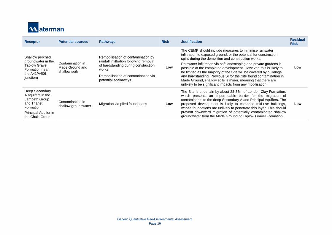
Receptor Potential sources Pathways Risk Justification Residual Risk
Shallow perched groundwater in the Taplow Gravel Formation near the A41/A406 junction)
Contamination in Made Ground and shallow soils.
Remobilisation of contamination by rainfall infiltration following removal of hardstanding during construction works.
Remobilisation of contamination via potential soakaways.
Low
The CEMP should include measures to minimise rainwater infiltration to exposed ground, or the potential for construction spills during the demolition and construction works. Rainwater infiltration via soft landscaping and private gardens is possible at the completed development. However, this is likely to be limited as the majority of the Site will be covered by buildings and hardstanding. Previous SI for the Site found contamination in Made Ground, shallow soils is minor, meaning that there are unlikely to be significant impacts from any mobilisation.
Low
Deep Secondary A aquifers in the Lambeth Group and Thanet Formation Principal Aquifer in the Chalk Group
Contamination in shallow groundwater. Migration via piled foundations Low
The Site is underlain by about 28-33m of London Clay Formation, which presents an impermeable barrier for the migration of contaminants to the deep Secondary A and Principal Aquifers. The proposed development is likely to comprise mid-rise buildings, whose foundations are unlikely to penetrate this layer. This should prevent downward migration of potentially contaminated shallow groundwater from the Made Ground or Taplow Gravel Formation.
Low

Generic Quantitative Geo-Environmental Assessment
Page 11
4. Rationale and Specific Objectives Soil Consultants undertook an intrusive ground investigation at the Phase 1BN Site between September and October 2016, designed by Waterman Infrastructure & Environment. This report comprises the environmental and geotechnical findings from this investigation, and previous investigations by Structural Soils.
Specific objectives for each Remediation Zone identified include:
• To assess the potential risk to future Site users and structures as a result of contamination identified in the Made Ground and shallow groundwater not to be excavated for basements or Site levelling;
• To characterise the ground gas and vapour regime and determine whether ground gas or vapours within the strata not to be excavated as part of the development pose a risk to future Site users and structures;
• To determine the risk posed by shallow groundwater contamination to deeper aquifers;
• Preliminary assessment of the likely classification of waste soils arising from the development, in particular the Made Ground to be removed from the Site as part of basement excavation and Site levelling;
• Geotechnical investigation of the ground beneath the Site to inform preliminary foundation design, and identify potential geotechnical issues which could impact the development; and
• Soakaway testing to inform the potential for use of drainage soakaways at the completed development.
Generic Quantitative Geo-Environmental Assessment
Page 12
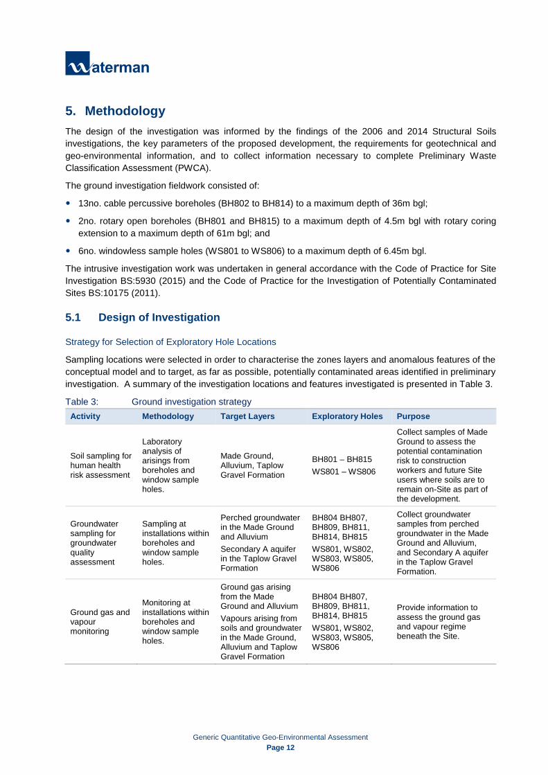
5. Methodology The design of the investigation was informed by the findings of the 2006 and 2014 Structural Soils investigations, the key parameters of the proposed development, the requirements for geotechnical and geo-environmental information, and to collect information necessary to complete Preliminary Waste Classification Assessment (PWCA).
The ground investigation fieldwork consisted of:
13no. cable percussive boreholes (BH802 to BH814) to a maximum depth of 36m bgl;
2no. rotary open boreholes (BH801 and BH815) to a maximum depth of 4.5m bgl with rotary coring extension to a maximum depth of 61m bgl; and
6no. windowless sample holes (WS801 to WS806) to a maximum depth of 6.45m bgl.
The intrusive investigation work was undertaken in general accordance with the Code of Practice for Site Investigation BS:5930 (2015) and the Code of Practice for the Investigation of Potentially Contaminated Sites BS:10175 (2011).
5.1 Design of Investigation
Strategy for Selection of Exploratory Hole Locations
Sampling locations were selected in order to characterise the zones layers and anomalous features of the conceptual model and to target, as far as possible, potentially contaminated areas identified in preliminary investigation. A summary of the investigation locations and features investigated is presented in Table 3.
Table 3: Ground investigation strategy Activity Methodology Target Layers Exploratory Holes Purpose
Soil sampling for human health risk assessment
Laboratory analysis of arisings from boreholes and window sample holes.
Made Ground, Alluvium, Taplow Gravel Formation
BH801 – BH815 WS801 – WS806
Collect samples of Made Ground to assess the potential contamination risk to construction workers and future Site users where soils are to remain on-Site as part of the development.
Groundwater sampling for groundwater quality assessment
Sampling at installations within boreholes and window sample holes.
Perched groundwater in the Made Ground and Alluvium Secondary A aquifer in the Taplow Gravel Formation
BH804 BH807, BH809, BH811, BH814, BH815 WS801, WS802, WS803, WS805, WS806
Collect groundwater samples from perched groundwater in the Made Ground and Alluvium, and Secondary A aquifer in the Taplow Gravel Formation.
Ground gas and vapour monitoring
Monitoring at installations within boreholes and window sample holes.
Ground gas arising from the Made Ground and Alluvium Vapours arising from soils and groundwater in the Made Ground, Alluvium and Taplow Gravel Formation
BH804 BH807, BH809, BH811, BH814, BH815 WS801, WS802, WS803, WS805, WS806
Provide information to assess the ground gas and vapour regime beneath the Site.

Generic Quantitative Geo-Environmental Assessment
Page 13
Activity Methodology Target Layers Exploratory Holes Purpose
Geotechnical investigation
In-situ testing in boreholes and laboratory analysis of arisings.
Taplow Gravel Formation, London Clay Formation, Lambeth Group.
BH801 – BH815
Establish the depth to the top of the London Clay Formation and Lambeth Group. Undertake in-situ Standard Penetration Testing (SPT) to inform foundation design. Collect samples of the Taplow Gravel Formation and London Clay Formation for geotechnical testing.
Soil sampling for Preliminary Waste Classification assessment
Sampling arisings from boreholes and window sample holes.
Made Ground, Alluvium, Taplow Gravel Formation
BH801 – BH815 WS801 – WS806
Collect samples of Made Ground, Alluvium and Taplow Gravel Formation likely to be excavated for basements at the development, for PWCA.
Soakage tests
Soakaway testing in three boreholes and window sample holes.
Taplow Gravel Formation
WS806, BH809, BH814
Inform drainage assessment at the Site.
California Bearing Ratio (CBR) tests
CBR testing at seven locations. Made Ground CBR1 – CBR7
Provide geotechnical information for foundation design.
Sampling Strategy
Soil samples were collected at 0.5m intervals in the Made Ground, at every change of strata, and where evidence of visual or olfactory contamination was identified. In the underlying superficial deposits samples were collected at 1.0m intervals up to the head of the London Clay Formation. Soil samples were analysed for a range of organic and inorganic contaminants, asbestos identification and quantification, and Waste Acceptance Criteria (WAC) analysis.
Headspace analysis to monitor for volatile organic compounds (VOC) was carried out on all samples collected.
Bulk samples for geotechnical analysis were collected at 1.0m intervals during borehole drilling with UT100 sampling completed at regular intervals in accordance with the UK Specification for Ground Investigation (2011, Section 7.54).
5.2 Quality Control Environmental samples were despatched in regularly under a chain of custody procedure to ESG, a UKAS accredited laboratory. Samples were stored within cool boxes containing ice packs during transport.
All contractors, including laboratories, used during this project have been approved by Waterman as a part of in-house Integrated Management System (BS ISO 9001, BS ISO 14001) procedure. This requires all third parties to demonstrate competence and a high standard of work during a regular audit scheme.

Generic Quantitative Geo-Environmental Assessment
Page 14
5.3 Health and Safety All supervision work carried out on-Site by Waterman was in accordance with Waterman Group Health & Safety policy. Contractors and subcontractors worked to their own risk assessments and method statements.

Generic Quantitative Geo-Environmental Assessment
Page 15
6. Site Activities The ground investigation was carried out in stages, shown in chronological order of the works undertaken in Table 4.
Table 4: Summary of fieldwork activities Phase of Work. Activity Contractor Date Supervision
Service survey Scanning for buried services.
Subscan services
September – October 2016 Soil Consultants
UXO surveying Downhole magnetometer probing at each location. 1st Line Defence September –
October 2016 Soil Consultants
Ground Investigation
6no. window sample holes to maximum depth of 6.5m bgl
Soil Consultants September – October 2016
Soil Consultants, Waterman
15no. cable percussion and rotary open/core boreholes to 61m bgl maximum depth. 3no. soakage tests undertaken at 3 to 5m bgl 7no. CBR tests undertaken at 0.4 to 0.6m bgl
Monitoring Well Installation
11no. monitoring well installations to 55.5m bgl max. depth. 2no. piezometer installations in the Lambeth Group
Soil Consultants September – October 2016
Soil Consultants, Waterman
Groundwater sampling Sampling of groundwater in monitoring wells using low-flow techniques.
Terragen Environmental
November 2016 Soil Consultants
Groundwater, ground gas and vapour monitoring
Gas and vapour monitoring at the installed wells on six occasions (four visits completed to date.)
Terragen Environmental
November 2016 – February 2017
Soil Consultants
Note: m bgl = metres below ground level
6.1 Services and Drainage Survey Site management provided drainage plans for the investigation area. A services survey utilising CAT scanning and ground-penetrating radar scanning was undertaken ahead of drilling at each location. Hand pits were also dug at each location to 1.2m depth before drilling commenced to check for unmapped buried services.
Historical information available for the Site highlighted a potential risk of unexploded bombs and ordnance (UXO) present beneath the Site. To reduce the risk of encountering UXO during the works, all exploratory holes were cleared by 1st Line Defence before commencement of the ground investigation operations.

Generic Quantitative Geo-Environmental Assessment
Page 16
6.2 Soil Sampling
Environmental sampling
During excavation, all arisings were placed on plastic sheeting to prevent cross-contamination of soil. Representative soil samples were collected from arisings every 0.5m in the Made Ground, and every 1.0m in the natural material. Samples were sealed in one litre plastic tubs with airtight lids, phials and glass jars containing preservatives, as appropriate. The soil samples taken were subject to screening with a photoionisation detector (PID).
Samples collected were analysed for a range of inorganic and hydrocarbon contaminants including metals, total petroleum hydrocarbons (TPH), polyaromatic hydrocarbons (PAHs), volatile organic compounds (VOCs) and semi-volatile organic compounds (SVOCs).
Samples of the Made Ground and Alluvium from the area to be excavated for basements at the development were also submitted for Waste Acceptance Criteria testing.
All exploratory holes were logged and sampled for contamination purposes by Soil Consultants Ltd.
Geotechnical sampling
Standard Penetration Tests (SPT) and UT100 sampling were completed at regular intervals in all boreholes. Bulk samples were also collected at 1.0m intervals during borehole drilling. Full results and interpretation are presented in the Soil Consultants factual report in Appendix B.
6.3 Installations On completion of drilling, a 50mm diameter HDPE standpipe with gas tap and bung was installed in five of the six window sample holes, and eight of the fifteen boreholes. Two of the wells were installed with vibrating wire piezometers. The intake section for each installation comprised a length of slotted HDPE pipe surrounded by pea shingle. Where possible a 1m section of plain pipe was included beneath the intake to act as a sump. The remainder of the installation used plain pipe to ground level, surrounded by bentonite. A secure weather-proofing cap finished each location at ground level. Further details for all boreholes and window sample holes are included within the Soil Consultants factual report in Appendix B.
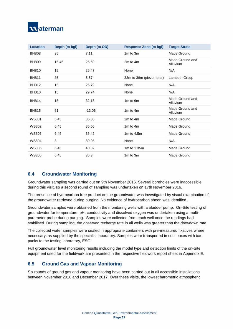
Installations were targeted to enable future ground gas and vapour monitoring, and groundwater monitoring and sampling. Details for the installations are in Table 5.
Table 5: Installed monitoring wells and target strata Location Depth (m bgl) Depth (m OD) Response Zone (m bgl) Target Strata
BH801 55.5 -11.91 48m to 51m (piezometer) Lambeth Group
BH802 15 27.74 None N/A
BH803 15 27.39 None N/A
BH804 35 7.11 1m to 5m Made Ground
BH805 15 26.33 None N/A
BH806 15.45 25.79 None N/A
BH807 15.45 27.15 2m to 4m Alluvium
Generic Quantitative Geo-Environmental Assessment Page 17
Location Depth (m bgl) Depth (m OD) Response Zone (m bgl) Target Strata
BH808 35 7.11 1m to 3m Made Ground
BH809 15.45 26.69 2m to 4m Made Ground and Alluvium
BH810 15 26.47 None N/A
BH811 36 5.57 33m to 36m (piezometer) Lambeth Group
BH812 15 26.79 None N/A
BH813 15 29.74 None N/A
BH814 15 32.15 1m to 6m Made Ground and Alluvium
BH815 61 -13.06 1m to 4m Made Ground and Alluvium
WS801 6.45 36.06 2m to 4m Made Ground
WS802 6.45 36.06 1m to 4m Made Ground
WS803 6.45 35.42 1m to 4.5m Made Ground
WS804 3 39.05 None N/A
WS805 6.45 40.82 1m to 1.35m Made Ground
WS806 6.45 36.3 1m to 3m Made Ground
6.4 Groundwater Monitoring Groundwater sampling was carried out on 9th November 2016. Several boreholes were inaccessible during this visit, so a second round of sampling was undertaken on 17th November 2016.
The presence of hydrocarbon free product on the groundwater was investigated by visual examination of the groundwater retrieved during purging. No evidence of hydrocarbon sheen was identified.
Groundwater samples were obtained from the monitoring wells with a bladder pump. On-Site testing of groundwater for temperature, pH, conductivity and dissolved oxygen was undertaken using a multi-parameter probe during purging. Samples were collected from each well once the readings had stabilised. During sampling, the observed recharge rate in all wells was greater than the drawdown rate.
The collected water samples were sealed in appropriate containers with pre-measured fixatives where necessary, as supplied by the specialist laboratory. Samples were transported in cool boxes with ice packs to the testing laboratory, ESG.
Full groundwater level monitoring results including the model type and detection limits of the on-Site equipment used for the fieldwork are presented in the respective fieldwork report sheet in Appendix E.
6.5 Ground Gas and Vapour Monitoring Six rounds of ground gas and vapour monitoring have been carried out in all accessible installations between November 2016 and December 2017. Over these visits, the lowest barometric atmospheric

Generic Quantitative Geo-Environmental Assessment
Page 18
pressure encountered was 992 mBar upon arrival, which rose to 994 mBar by completion of the monitoring.
The peak and steady concentration readings of methane, carbon dioxide and oxygen as % volume of total gas (% v/v), the % of lower explosive limit, and hydrogen sulphide and carbon monoxide levels as parts per million (ppm) were recorded at each installed monitoring standpipe. Readings were collected with a GFM430 infrared gas analyser. Vapour levels in monitoring wells were recorded as ppm with a photoionisation detector (PID).
Full ground gas and vapour monitoring results including the model type and detection limits of the on-Site equipment used for the fieldwork are presented in Appendix E.

Generic Quantitative Geo-Environmental Assessment
Page 19
7. Ground Conditions and Material Properties Detailed logs of the strata encountered, together with records of the samples taken during the investigation are provided in the Soil Consultants factual report in Appendix B. Relevant borehole window sample and trial pit logs from the 2006 and 2014 Structural Soils ground investigations have informed the interpretation of the ground conditions:
• BH412 to BH427; BH430, BH433, BH434, BH454, BH461 to BH464, BH469, BH472, BH479 to BH481 and BH487;
• WS601, WS644, WS676 to WS683, WS691 and WS6108 to WS6110; and • TP503, TP505, TP506, TP508, TP512, TP519, TP520, TP522, TP549 to TP551, TP566 and
TP584.
A summary of the geological strata encountered is presented below.
7.1 Geological Strata The strata encountered in the investigation was generally consistent with the geology identified in the outline conceptual model. Table 6 below provides an updated review of the geology present across the Site.
Table 6: Ground Summary
Stratum Depth to Top of Stratum (m bgl)
Thickness (m) Description
Made Ground
0.00 0.08 – 0.45 Tarmac/Concrete
0.00 – 0.05 0.15 – 0.20 Topsoil - located with two exploratory holes only, BH806 and TP522.
0.00 0.20 – 6.50
Grey to dark brown, silty sand and gravel to, soft to stiff, dark brown and green grey to dark grey /dark brown silty, slightly sandy to sandy, slightly gravelly to gravelly clay. Gravel comprising flint, brick, concrete, wood, clinker, glass and possible asbestos containing material is angular to rounded with occasional pockets of ash; silt and sand; and gravelly to very gravelly clay.
Alluvium 0.90 – 6.00 0.40 – 5.85
Soft to firm, green and brown mottled dark brown and dark brown and black, silty to very silty, slightly sandy, gravelly to very gravelly clay with occasional sand partings; and medium dense orange brown to brown grey slightly clayey to clayey sand and gravel. Occasional rootlets, rare black staining and peat are noted. Gravel is angular to subrounded fine to coarse medium flint and chert.
Taplow Gravel Formation
1.50 - 5.00 0.80 – 1.65
Loose to very dense orange brown to brown slightly clayey to clayey, silty, sandy to very sandy gravel and grey and white sand and gravel; and firm to stiff brown orange mottled grey gravelly clay. Gravel is subrounded fine to coarse flint with occasional pockets of brown sandy very gravelly clay. Encountered sporadically across the site at depth below Made Ground or Alluvium.

Generic Quantitative Geo-Environmental Assessment
Page 20
Stratum Depth to Top of Stratum (m bgl)
Thickness (m) Description
London Clay Formation 0.20 – 7.80 28.00 – 34.60
Firm to very stiff; occasionally soft; occasionally fissured; dark brown mottled brown/orange to dark grey sometimes slightly sandy, silty clay with occasional selenite crystals and silt partings sand partings. Encountered at depth below Made Ground, Alluvium or Taplow Gravel Formation. Encountered in all boreholes.
Lam
beth
Gro
up
Reading Formation 31.73 – 35.88 3.27 – 11.97
Very stiff fissured light grey to grey mottled red/brown and yellow/brown light grey mottled yellow/purple, slightly sandy silty clay with rare pockets/lenses of silt and sand; and rare relic rootlets. Encountered in BH414; BH419; BH424; BH426; BH472; BH801, BH804, BH808, BH811 and in BH815.
Upnor Formation 44.05 – 50.00 0.95 - 6.90
Grey to black, brown and white slightly clayey to clayey, slightly sandy gravel; and very stiff, light bluish green mottled yellowish brown to black to dark grey, slightly gravelly, sometimes sandy, silty clay with lenses of light grey silt and sand. Gravel is subangular to rounded, fine to coarse of flint. Encountered in BH414; BH426; BH434, BH801; and in BH815
Thanet Formation 52.0 – 53.68 0.31 – 6.50
Dark grey slightly sandy clayey gravel and cobbles with some dark greenish grey gravelly silty clay; and stiff dark grey mottled dark green; and dark grey silty very sandy, gravelly clay. Encountered in BH426; BH434; BH801 and BH815.
Chalk Group (Bedrock) 52.8 – 56.9 > 4.1
Weak to very weak, low to medium density off white chalk with rare weathered surface and rare to occasional flint. Encountered in BH426; BH434; BH801; and BH815.
7.2 Made Ground Made Ground was encountered in all boreholes from ground surface (0m bgl) to a maximum depth of 6.70m bgl (BH806). Asphalt was encountered in all exploratory holes except BH412, BH418A, BH419, BH461, BH469, TP512, TP522, TP584, WS601, WS6109, WS6110, BH806 and BH810. Where present, asphalt extended from ground level to a maximum depth of 0.23m bgl (WS677).
Made Ground was encountered in BH806 as topsoil from ground level to 0.20m bgl. In TP522, wood chippings were located at surface to a depth of 0.05m, overlying topsoil from 0.05m bgl to 0.20m bgl.
In BH801, BH811, BH813 and WS804 asphalt was found overlying concrete to a maximum depth 0.45m bgl. In BH469 a 0.06m thick paving slab was located at the surface.
Made Ground was initially encountered as concrete in BH418A, BH461 and in BH810 from ground level to a maximum depth of 0.40m bgl (BH810).
Located below the asphalt, topsoil or concrete, the Made Ground was encountered as grey to dark brown, silty sand and gravel; and soft to stiff, dark brown and green grey to dark grey/dark brown silty, slightly
Generic Quantitative Geo-Environmental Assessment
Page 21
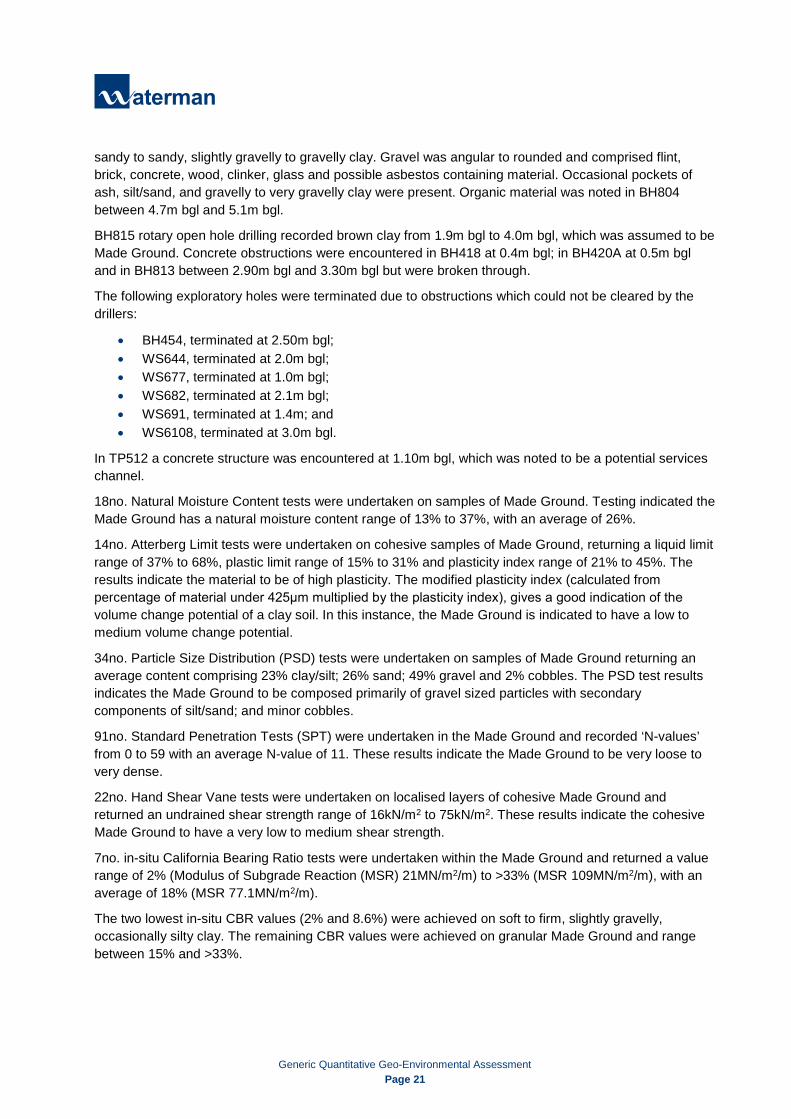
sandy to sandy, slightly gravelly to gravelly clay. Gravel was angular to rounded and comprised flint, brick, concrete, wood, clinker, glass and possible asbestos containing material. Occasional pockets of ash, silt/sand, and gravelly to very gravelly clay were present. Organic material was noted in BH804 between 4.7m bgl and 5.1m bgl.
BH815 rotary open hole drilling recorded brown clay from 1.9m bgl to 4.0m bgl, which was assumed to be Made Ground. Concrete obstructions were encountered in BH418 at 0.4m bgl; in BH420A at 0.5m bgl and in BH813 between 2.90m bgl and 3.30m bgl but were broken through.
The following exploratory holes were terminated due to obstructions which could not be cleared by the drillers:
• BH454, terminated at 2.50m bgl; • WS644, terminated at 2.0m bgl; • WS677, terminated at 1.0m bgl; • WS682, terminated at 2.1m bgl; • WS691, terminated at 1.4m; and • WS6108, terminated at 3.0m bgl.
In TP512 a concrete structure was encountered at 1.10m bgl, which was noted to be a potential services channel.
18no. Natural Moisture Content tests were undertaken on samples of Made Ground. Testing indicated the Made Ground has a natural moisture content range of 13% to 37%, with an average of 26%.
14no. Atterberg Limit tests were undertaken on cohesive samples of Made Ground, returning a liquid limit range of 37% to 68%, plastic limit range of 15% to 31% and plasticity index range of 21% to 45%. The results indicate the material to be of high plasticity. The modified plasticity index (calculated from percentage of material under 425μm multiplied by the plasticity index), gives a good indication of the volume change potential of a clay soil. In this instance, the Made Ground is indicated to have a low to medium volume change potential.
34no. Particle Size Distribution (PSD) tests were undertaken on samples of Made Ground returning an average content comprising 23% clay/silt; 26% sand; 49% gravel and 2% cobbles. The PSD test results indicates the Made Ground to be composed primarily of gravel sized particles with secondary components of silt/sand; and minor cobbles.
91no. Standard Penetration Tests (SPT) were undertaken in the Made Ground and recorded ‘N-values’ from 0 to 59 with an average N-value of 11. These results indicate the Made Ground to be very loose to very dense.
22no. Hand Shear Vane tests were undertaken on localised layers of cohesive Made Ground and returned an undrained shear strength range of 16kN/m2 to 75kN/m2. These results indicate the cohesive Made Ground to have a very low to medium shear strength.
7no. in-situ California Bearing Ratio tests were undertaken within the Made Ground and returned a value range of 2% (Modulus of Subgrade Reaction (MSR) 21MN/m2/m) to >33% (MSR 109MN/m2/m), with an average of 18% (MSR 77.1MN/m2/m).
The two lowest in-situ CBR values (2% and 8.6%) were achieved on soft to firm, slightly gravelly, occasionally silty clay. The remaining CBR values were achieved on granular Made Ground and range between 15% and >33%.

Generic Quantitative Geo-Environmental Assessment
Page 22
Assuming the lowest two CBR results are associated with soft spots related to cohesive pockets, it could reasonably be assumed that granular Made Ground will provide a minimum CBR 15%. However, the extent of soft spots is unproven and hence CBR values are likely to be highly variable over the footprint of the scheme.
Three Undrained Unconsolidated Triaxial tests were undertaken on cohesive samples of Made Ground and returned an undrained shear strength range of 20kN/m2 to 56kN/m2 indicting the samples tested to have a very low to medium undrained shear strength.
One dry density / moisture content relationship test using a 2.5kg rammer was undertaken on an amalgamated sample of Made Ground from BH464 at 0.2m bgl and 0.6m bgl. This Made Ground sample was an amalgamation of firm slightly sandy gravelly clay with slightly sandy clayey gravel. The gravel from the two original samples was noted to comprise flint, granite, slate, brick, concrete, wood, plastic and charcoal. The test returned an initial natural moisture content of 8.7%; a bulk density of 2.65 Mg/m3, maximum dry density of 2.00Mg/m3; an optimum moisture content of 10% and achieved a compaction of 95%. This test indicates that the sampled Made Ground sits approximately at its optimum moisture content level.
Six organic content tests were undertaken on samples of Made Ground and returned a value range of 3.2% to 12%.
Geotechnical test results are summarised in Table 7. Full results for individual tests are detailed in Tables E.1 to E.8 within Appendix C.
Table 7: Made Ground – Summary of Geotechnical Test Results
Test No. of Tests
Range Average Suggested Characteristic Value
Natural Moisture Content (%) 18 13% to 37% 26% 26%
Liquid Limit (%) 14 37% to 68% 57% 57%
Plastic Limit (%) 14 15% to 31% 25% 25%
Plasticity Index (%) 14 21% to 45% 32% 32%
Density kN/m3 (based on Figure 1, BS:8002 (2015) - - - 18 kN/m3
California Bearing Ratio (%) - clay 7 2.0% to >33% 18% 2.0% to >33%
SPT N-values 75 0 to 59% 11% 11
Organic Content (%) 6 3.2 to 12% 8.7% 12%
Undrained Shear Strength (Total Stress Condition)
Hand Shear Vane Tests - cohesive layers (kN/m2) 22 16 75kN/m2 Cu = 40kN/m2
Φ = 0° Undrained Multistage Triaxial Cu (kN/m2) 3 20 to 56 40kN/m2
Drained Shear Strength (Effective Stress Condition) **
Correlation from SPT N-values (Peck et al) *** 75 20° to 42° 30° C’ = 0 kN/m2
Φ = 30°

Generic Quantitative Geo-Environmental Assessment
Page 23
*Stroud and Butler, 1975, Standard Penetration test and the Engineering Properties of Glacial Materials, The Engineering Behaviour of Glacial Materials, The Midland Soil Mechanics and Foundation Engineering Society. **Only to be applied for long term analysis of conditions when drained conditions prevail. *** Peck, R.B., Hanson, W.E. and Thornburn, T. H., Foundation Engineering, 2nd Edition 1967.
7.3 Alluvium Alluvium was encountered below Made Ground in 22no. exploratory holes from various depths between 0.9m bgl (BH419) to 6.0m bgl (BH421 and BH481) to a maximum depth in BH420 at 7.8m bgl.
The Alluvium is described as soft to firm, green and brown mottled dark brown and dark brown and black, silty to very silty, slightly sandy, gravelly to very gravelly clay with occasional sand partings; and medium dense orange brown to brown grey slightly clayey to clayey sand and gravel with occasional cobbles. Occasional rootlets, rare black staining and peat were noted. Gravel was angular to subrounded, fine to coarse medium flint and chert. Organic odour was noted in WS801 and WS802.
26no. Natural Moisture Content tests were undertaken on samples of Alluvium. The results indicate the Alluvium to have an average natural moisture content of 29%.
25no. Atterberg Limits tests were undertaken on samples of Alluvium returning a liquid limit range of 37% to 80%; plastic limit range of 17% to 37% and plasticity index range of 17% to 55%. The results indicate the material to be of high plasticity. The modified plasticity index (calculated from percentage of material under 425μm multiplied by the plasticity index), gives a good indication of the volume change potential of a clay soil. In this instance, the Alluvium is indicated to have a low to medium volume change potential.
21no. Particle Size Distribution (PSD) tests were undertaken on the cohesive and non-cohesive samples of Alluvium. The cohesive layers returned an average content comprising 67% clay/silt; 12% sand and 21% gravel. The non-cohesive layers returned an average content comprising 11% clay/silt; 23% sand; 64% gravel and 2% cobbles.
26no. Standard Penetration Tests (SPT) were undertaken in the Alluvium within both the cohesive and non-cohesive layers; and recorded N-values of 1 and 54 with an average N-value of 13. These results indicate the cohesive Alluvium to be very soft to stiff. An average N-value of 8 was returned, which correlates with the borehole logs descriptions of soft to firm Clay. The non-cohesive Alluvium is indicated to be loose to very dense with an average N-value of 18 returned. Again this correlates with the borehole log descriptions of medium dense Gravel. The average values have been assessed as the characteristic values in the summary in Table 8.

Generic Quantitative Geo-Environmental Assessment
Page 24
From the SPT results, it is possible to derive an estimation of undrained shear strength using the following correlation (Stroud and Butler, 1975):
cu = f1N
Where,
cu is the undrained shear strength (kN/m2)
N is the SPT blow count
f1 is a factor depending upon plasticity.
For the Alluvium clays having an average plasticity index of 32%, f1 = 4.5 with a minimum and maximum SPT test values of N=1 and N=26 respectively, this results in an undrained shear strength range of 4.5kN/m2 to 117kN/m2. Due to the variability of SPT N-values obtained within the Alluvium, the average value of 8 has been used to calculate the undrained shear strength. This results in an undrained shear strength of 36kN/m2.
11no. Undrained Unconsolidated Triaxial tests (7No. Single stage and 4No. Multistage tests) were carried out on undisturbed samples of Alluvium. The results indicated angle of internal friction Ø range of 0° to 2.8° and an undrained cohesion (i.e. Cu) of 26kN/m2 and 72kN/m2 suggesting that the materials tested were of ‘low to medium’ strength. Bulk density ranges from 1.82Mg/m3 to 2.18Mg/m3.
The ‘low to medium’ shear strength clay sample tested above correlates with the borehole log descriptions which suggest that the cohesive Alluvium is a soft to firm material, and the undrained shear strength based on plasticity index and SPT N-values (Stroud and Butler).
12no. Hand Shear Vane tests were undertaken on the Alluvium and returned an undrained shear strength range of 2kN/m2 to 62kN/m2. These results indicate the Alluvium to be ‘soft’ to ‘firm’, and to have a ‘very low’ to ‘medium’ shear strength.
Self-boring pressuremeter testing was undertaken within the Alluvium in two boreholes: BH415 at 2.50m bgl and BH433 at 7.50m bgl providing an Initial Modulus (Gi) range of 3MN/m2 to 16MN/m2. These results are given in Table C. 15 in Appendix C.
For the purposes of assigning characteristic values, it is recommended that a conservative approach be adopted and a Cu value of 30kN/m2 is suggested. The internal friction angle of the material should be assumed as 0°.
For analysis of long term drained conditions, three Consolidated Undrained Triaxial Tests were carried out on undisturbed samples of Alluvium Deposit. The results indicated an effective angle of internal friction Ø’ range of 25.5° to 33.5° with an average Ø’ = 29°; and an effective cohesion (i.e. C’) of 3kN/m2 and 13kN/m2 with an average C’ = 10kN/m2. Correlating angle of shear resistance from SPT N-values (based on Peck et al.), produces an average angle of shear resistance of <28°.
It has been assumed the internal friction angle will increase to a maximum of 20° with cohesion conservatively assumed as zero. It should be noted that this will only apply in situations where drained conditions prevail, such as the long term analysis of cut slopes.

Generic Quantitative Geo-Environmental Assessment
Page 25
3no. One Dimensional Consolidation tests were undertaken on representative samples of Alluvium. The results indicate that the Alluvium has a Coefficient of Volume Compressibility value range of 0.13m2/MN to 0.75m2/MN. This indicates the soil to have a medium to high compressibility (Tomlinson, 2001)1.
One organic content test was undertaken on a sample of Alluvium, and returned a value of 6%.
A summary of the characteristic material values recommended for design is given in Table 8. Full results for individual tests are detailed in Tables C.9 to C.18 within Appendix C.
Table 8: Alluvium – Summary of Geotechnical Test Results
Test No. of Tests Range Average Suggested
Characteristic Value
Natural Moisture Content (%) 25 8% to 46% 29% 29%
Liquid Limit (%) 25 37% to 80% 57% 57%
Plastic Limit (%) 25 17% to 37% 25% 25%
Plasticity Index (%) 25 17% to 55% 32% 32%
SPT N-values 2 5 to 6 5 5
Organic Content (%) 1 6 6% 6%
Density kN/m3 (Undrained Single stage, Multistage and Consolidated Undrained Triaxial; and one-dimension consolidation tests)
18 18.2 to 21.8 19.5 19 kN/m3
Coefficient of Compressibility (m2/MN) 3 0.13 to 0.75 0.275 0.75m2/MN
Undrained Shear Strength (Total Stress Condition)
Correlation from SPT N-values and plasticity index (Stroud and Butler) – Clay layer* 12 4.5 to 117 34.5kN/m2
Cu = 30kN/m2
Φ = 0° Undrained Single Stage and Multistage Triaxial Cu (kN/m2) 11 26 to 72 46kN/m2
Hand Shear Vane Tests – cohesive layers (kN/m2) 12 2 to 62 26kN/m2
Drained Shear Strength (Effective Stress Condition) **
Consolidated Undrained Triaxial Tests 3 25.5° to 33.5° 29° C’ = 0 kN/m2
Φ = 20° Correlation from SPT N-values (Peck et al)*** 2 <28 <28
*Stroud and Butler, 1975, Standard Penetration test and the Engineering Properties of Glacial Materials, The Engineering Behaviour of Glacial Materials, The Midland Soil Mechanics and Foundation Engineering Society. **Only to be applied for long term analysis of conditions when drained conditions prevail. *** Peck, R.B., Hanson, W.E. and Thornburn, T. H., Foundation Engineering, 2nd Edition 1967.
1 Tomlinson, M.J. (2001) Foundation Design and Construction, Pearson Prentice Hall, Harlow England.

Generic Quantitative Geo-Environmental Assessment
Page 26
7.4 Taplow Gravel Formation The Taplow Gravel Formation was encountered at depth below Made Ground or Alluvium in BH412, BH425, BH487, WS601, WS683, BH803 and BH814, at varying depths between 1.5m bgl (BH803) to 5.0m bgl (BH487) to a maximum depth of 7.8m bgl (BH814). The Taplow Gravel Formation is described as loose to very dense, orange-brown to brown, slightly clayey to clayey, silty, sandy to very sandy gravel with grey and white sand and gravel and firm to stiff, brown, orange mottled grey gravelly clay. Gravel is subrounded fine to coarse flint with occasional pockets of brown, sandy, very gravelly clay. WS683 was terminated at 7.0m bgl due to an obstruction within the gravel layer.
4no. Natural Moisture Content tests were undertaken on samples of Taplow Gravel Formation. The results indicate the Taplow Gravel Formation to have an average natural moisture content of 19%.
3no. Atterberg Limits tests were undertaken on cohesive samples of the Taplow Gravel Formation returning a liquid limit range of 42% to 48%; plastic limit of 20% and plasticity index range of 22% to 38%. The results indicate the cohesive samples to be of intermediate to high plasticity. The modified plasticity index (calculated from percentage of material under 425μm multiplied by the plasticity index), gives a good indication of the volume change potential of a clay soil. In this instance, the cohesive samples of the Taplow Gravel Formation were indicated to have a low volume change potential.
7no. Particle Size Distribution (PSD) tests were undertaken on the cohesive samples of Taplow Gravel Formation, returning an average content comprising 18% clay/silt; 20% sand; 60% gravel and 2% cobbles. Although, the Atterberg tests have returned values indicting a clay/silt with an intermediate to high plasticity, these tests were undertaken on the cohesive fractions of the formation. The PSD results indicate the Taplow Gravel Formation to be comprised predominantly by Gravel with some Sand and a minor component of Clay/Silt.
10no. Standard Penetration Tests (SPTs) were undertaken in the Taplow Gravel Formation and recorded N-values of 6 to >50 with an average N-value of 25. These results indicate the Taplow Gravel Formation to be loose to very dense. Due to the variability of SPT N-values obtained between 1.2m bgl and 6.0m bgl, and assuming the N= 6 to be anomalous testing return, the average N-value increase to N=27 and lowest N-value of 10 (worst case scenario) has been assessed as the characteristic value (Table 9). The internal friction angle (Φ’) for the Taplow Gravel Formation has been correlated from the SPT N-values based on Peck et al (1967) and returned an internal friction angle range of 28° to 43°.
2no. organic content tests were undertaken on samples of the Taplow Gravel Formation and returned a value range of 5% to 9%.
A summary of the characteristic material values recommended for design is given in Table 9. Full results for individual tests are detailed in Tables C.19 to C.22 within Appendix C.
Table 9: Taplow Gravel Formation – Summary of Geotechnical Test Results
Test No. of Tests
Range Average Suggested Characteristic Value
Natural Moisture Content (%) 4 11% to 32% 19% 19%
SPT N-values 10 10 to >50 27 10
Organic Content (%) 2 5 to 9 7 9%
Density kN/m3 (Figure 1, BS:8002, 2015) - - - 19 kN/m3
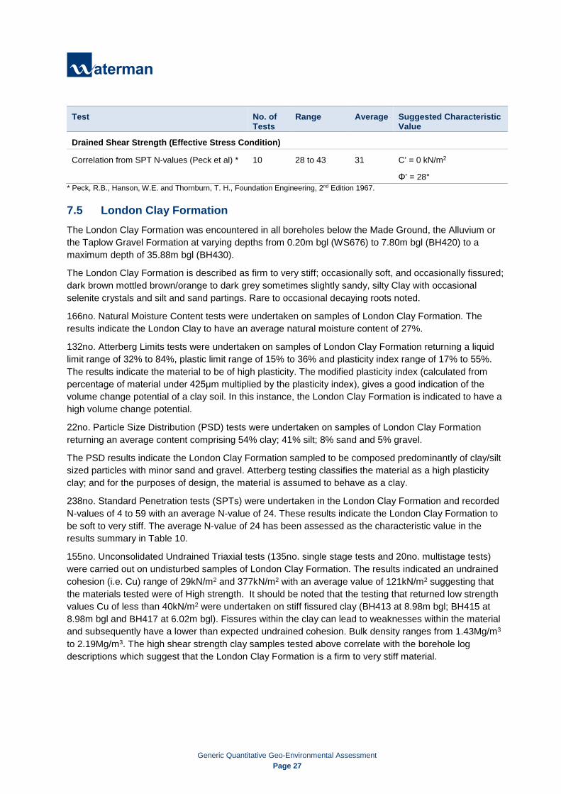
Generic Quantitative Geo-Environmental Assessment
Page 27
Test No. of Tests
Range Average Suggested Characteristic Value
Drained Shear Strength (Effective Stress Condition)
Correlation from SPT N-values (Peck et al) * 10 28 to 43 31 C’ = 0 kN/m2
Φ’ = 28° * Peck, R.B., Hanson, W.E. and Thornburn, T. H., Foundation Engineering, 2nd Edition 1967.
7.5 London Clay Formation The London Clay Formation was encountered in all boreholes below the Made Ground, the Alluvium or the Taplow Gravel Formation at varying depths from 0.20m bgl (WS676) to 7.80m bgl (BH420) to a maximum depth of 35.88m bgl (BH430).
The London Clay Formation is described as firm to very stiff; occasionally soft, and occasionally fissured; dark brown mottled brown/orange to dark grey sometimes slightly sandy, silty Clay with occasional selenite crystals and silt and sand partings. Rare to occasional decaying roots noted.
166no. Natural Moisture Content tests were undertaken on samples of London Clay Formation. The results indicate the London Clay to have an average natural moisture content of 27%.
132no. Atterberg Limits tests were undertaken on samples of London Clay Formation returning a liquid limit range of 32% to 84%, plastic limit range of 15% to 36% and plasticity index range of 17% to 55%. The results indicate the material to be of high plasticity. The modified plasticity index (calculated from percentage of material under 425μm multiplied by the plasticity index), gives a good indication of the volume change potential of a clay soil. In this instance, the London Clay Formation is indicated to have a high volume change potential.
22no. Particle Size Distribution (PSD) tests were undertaken on samples of London Clay Formation returning an average content comprising 54% clay; 41% silt; 8% sand and 5% gravel.
The PSD results indicate the London Clay Formation sampled to be composed predominantly of clay/silt sized particles with minor sand and gravel. Atterberg testing classifies the material as a high plasticity clay; and for the purposes of design, the material is assumed to behave as a clay.
238no. Standard Penetration tests (SPTs) were undertaken in the London Clay Formation and recorded N-values of 4 to 59 with an average N-value of 24. These results indicate the London Clay Formation to be soft to very stiff. The average N-value of 24 has been assessed as the characteristic value in the results summary in Table 10.
155no. Unconsolidated Undrained Triaxial tests (135no. single stage tests and 20no. multistage tests) were carried out on undisturbed samples of London Clay Formation. The results indicated an undrained cohesion (i.e. Cu) range of 29kN/m2 and 377kN/m2 with an average value of 121kN/m2 suggesting that the materials tested were of High strength. It should be noted that the testing that returned low strength values Cu of less than 40kN/m2 were undertaken on stiff fissured clay (BH413 at 8.98m bgl; BH415 at 8.98m bgl and BH417 at 6.02m bgl). Fissures within the clay can lead to weaknesses within the material and subsequently have a lower than expected undrained cohesion. Bulk density ranges from 1.43Mg/m3 to 2.19Mg/m3. The high shear strength clay samples tested above correlate with the borehole log descriptions which suggest that the London Clay Formation is a firm to very stiff material.
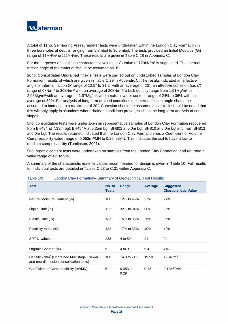
Generic Quantitative Geo-Environmental Assessment
Page 28
A total of 11no. Self-boring Pressuremeter tests were undertaken within the London Clay Formation in three boreholes at depths ranging from 5.8mbgl to 30.5mbgl. The tests provided an Initial Modulus (Gi) range of 11MN/m2 to 111MN/m2. These results are given in Table C.28 in Appendix C.
For the purposes of assigning characteristic values, a Cu value of 120kN/m2 is suggested. The internal friction angle of the material should be assumed as 0°.
20no. Consolidated Undrained Triaxial tests were carried out on undisturbed samples of London Clay Formation, results of which are given in Table C.29 in Appendix C. The results indicated an effective angle of internal friction Ø’ range of 12.5° to 31.2° with an average of 23°; an effective cohesion (i.e. c’) range of 0kN/m2 to 80kN/m2 with an average of 20kN/m2; a bulk density range from 1.91Mg/m3 to 2.03Mg/m3 with an average of 1.97Mg/m3; and a natural water content range of 24% to 36% with an average of 30%. For analysis of long term drained conditions the internal friction angle should be assumed to increase to a maximum of 20°. Cohesion should be assumed as zero. It should be noted that this will only apply in situations where drained conditions prevail, such as the long term analysis of cut slopes.
5no. consolidation tests were undertaken on representative samples of London Clay Formation recovered from BH434 at 7.33m bgl; BH454A at 5.25m bgl; BH802 at 5.0m bgl; BH810 at 6.0m bgl and from BH813 at 6.0m bgl. The results returned indicated that the London Clay Formation has a Coefficient of Volume Compressibility value range of 0.053m2/MN to 0.29m2/MN. This indicates the soil to have a low to medium compressibility (Tomlinson, 2001).
5no. organic content tests were undertaken on samples from the London Clay Formation, and returned a value range of 4% to 9%.
A summary of the characteristic material values recommended for design is given in Table 10. Full results for individual tests are detailed in Tables C.23 to C.31 within Appendix C.
Table 10: London Clay Formation– Summary of Geotechnical Test Results
Test No. of Tests
Range Average Suggested Characteristic Value
Natural Moisture Content (%) 166 12% to 45% 27% 27%
Liquid Limit (%) 132 32% to 84% 66% 66%
Plastic Limit (%) 132 15% to 36% 26% 26%
Plasticity Index (%) 132 17% to 55% 40% 40%
SPT N-values 238 4 to 59 24 24
Organic Content (%) 5 4 to 9 6.4 7%
Density kN/m3 (Undrained Multistage Triaxial and one-dimension consolidation tests)
180 14.3 to 21.9 19.53 19 kN/m3
Coefficient of Compressibility (m2/MN) 5 0.053 to 0.29
0.12 0.12m2/MN

Generic Quantitative Geo-Environmental Assessment
Page 29
Test No. of Tests
Range Average Suggested Characteristic Value
Undrained Shear Strength (Total Stress Condition)
Undrained Single Stage and Multistage Triaxial Cu (kN/m2)
155 29 to 377 121kN/m2 Cu = 120kN/m2
Φ = 0° Undrained Multistage Triaxial Friction Angle (Φ)
20 0° to 15.6° 5.11°
Drained Shear Strength (Effective Stress Condition) *
Consolidated Undrained Triaxial tests c’ 20 0 to 80 20 C’ = 0 kN/m2
Φ = 20° Consolidated Undrained Triaxial tests Φ’ 20 12.5 to 31.2 23 *Only to be applied for long term analysis of conditions when drained conditions prevail.
7.6 Reading Formation (Upper Lambeth Group) The Reading Formation was encountered in BH414, BH419, BH424, BH426, BH472, BH801, BH804, BH808, BH811 and in BH815 at various depths from 31.73m bgl to 38.6m bgl with a maximum thickness of 11.95m (BH414). It is described as very stiff occasionally hard, fissured light grey to grey, mottled red/brown, yellow/brown and light grey mottled yellow/purple, slightly sandy silty Clay with rare pockets/lenses of silt and sand; and rare relic rootlets.
19no. Natural Moisture Content test were undertaken on samples of Reading Formation. The results indicate an average natural moisture content of 19%.
7no. Atterberg Limits tests were undertaken on samples of Reading Formation returning a liquid limit range of 43% to 66%; plastic limit range of 16% to 28%; and plasticity index range of 27% to 38%. The results indicate the material to be of low to intermediate plasticity. The modified plasticity index (calculated from percentage of material under 425μm multiplied by the plasticity index), gives a good indication of the volume change potential of a clay soil. In this instance, the Reading Formation is indicated to have a medium volume change potential.
4no. Particle Size Distribution (PSD) tests were undertaken on samples of Reading Formation returning an average content comprising 56% clay; 34% silt; and 10% sand. Although the PSD results indicate the sampled Reading Formation to be composed predominantly of Clay/Silt sized particles with a minor component of Sand. Atterberg testing classifies the material as a low to intermediate plastic clay. For the purposes of design, the material should be assumed to behave as a clay.
9no. Standard Penetration Tests (SPT) were undertaken in the Reading Formation and recorded N- values of 40 to >50 with an average N-value of 47. These results indicate the sampled Reading Formation to be ‘hard’. Due to the variability of SPT N-values obtained between 34.0m bgl and 46.0m bgl, the lowest N-value of 40 (worst case scenario) has been assessed as the characteristic value.
18no. Unconsolidated Undrained Triaxial tests (14no. single stage and 4no. multistage tests) were carried out on undisturbed samples of the Reading Formation. Results indicate an undrained shear strength range of 72kN/m2 to 732kN/m2 with an average value of 296kN/m2 indicting the Reading Formation to have a Very High undrained shear strength.

Generic Quantitative Geo-Environmental Assessment
Page 30
29no. hand penetrometer tests were undertaken on samples of Reading Formation, returning an undrained cohesion (Cu) range of 87kN/m2 to >250kN/m2 indicting the Reading Formation to have a High to Very High undrained shear strength.
The high to very high shear strength clay sample tested above correlates with the borehole log descriptions which suggest the Reading Formation to be a very stiff material.
3no. Self-boring Pressuremeter tests were undertaken within the Reading Formation in boreholes BH414 at 32.7m bgl and BH426 at 39.5m bgl and at 45.5m bgl. The tests provided an Initial Modulus (Gi) range of 28 MN/m2 to 129MN/m2.
One Consolidated Undrained Triaxial test was carried out on an undisturbed sample of Reading Formation. The results indicate an effective angle of internal friction Ø’ of 14.5°; an effective cohesion (c’) of 54kN/m2; a bulk density of 2.15Mg/m3; and a natural water content of 20%.
For analysis of long term drained conditions, the consolidated undrained triaxial test in conjunction with the correlated angle of shear resistance from SPT N-values (based on Peck et al.), produces an average angle of shear resistance of 37°. This average is greater than the published values for the Reading Formation: Ø’=22° (Entwisle at al.,2013)2 and Ø’=28° to 32° (Burland, Standing and Jardine, 2001)3.
Assuming that the consolidated undrained triaxial test has produced an anomalous low result, a conservative value of Ø’=22° has been assumed as the characteristic value. Cohesion should be assumed as zero. It should be noted that this will only apply in situations where drained conditions prevail, such as the long term analysis of cut slopes.
A summary of the characteristic material values recommended for design is given in Table 11. Full results for individual tests are detailed in Tables C.32 to C.39 within Appendix C.
Table 11: Reading Formation – Summary of Geotechnical Test Results
Test No. of Tests
Range Average Suggested Characteristic Value
Natural Moisture Content (%) 19 12% to 31% 19% 19%
Liquid Limit (%) 7 43% to 66% 52% 52%
Plastic Limit (%) 7 16% to 28% 21% 21%
Plasticity Index (%) 7 27% to 38% 31% 31%
SPT N-values 9 40 to >50 47 40
Density kN/m3 (Undrained Multistage Triaxial and one-dimension consolidation tests) 19 17.2 to 23.4 21.2 19 kN/m3
Coefficient of Compressibility (m2/MN) 5 0.053 to 0.29 0.12 0.29m2/MN
2 D C Entwisle, P R N Hobbs, K J Northmore, J Skipper, M R Raines, S J Self, R A Ellison and L D Jones (2013) Engineering Geology of British Rocks and Soils - Lambeth Group, OPEN REPORT OR/13/006, British Geological Survey, Keyworth, Nottingham. 3 J.B Burland, J.R. Standing and F.M. Jardine (2001) Building Response to Tunnelling. Case studies from Construction of the Jubilee Line extension, London, SP200, CIRIA

Generic Quantitative Geo-Environmental Assessment
Page 31
Test No. of Tests
Range Average Suggested Characteristic Value
Undrained Shear Strength (Total Stress Condition)
Unconsolidated Undrained Triaxial (Single stage and Multistage) Cu (kN/m2)
14 72 to 732 296kN/m2 Cu = 300kN/m2
Φ = 0° Undrained Multistage Triaxial Friction Angle (Φ) 4 3.5° to 16.7° 10°
Hand Penetration Tests Cu (kN/m2) 29 87 to >250 213
Drained Shear Strength (Effective Stress Condition) *
Consolidated Undrained Triaxial C’(kN/m2) 1 54 54 C’ = 0 kN/m2
Φ = 22 Friction Angle Φ’ (Consolidated Undrained Triaxial and Correlation from SPT N-values (Peck et al) **
10 14.5° 37°
*Only to be applied for long term analysis of conditions when drained conditions prevail. ** Peck, R.B., Hanson, W.E. and Thornburn, T. H., Foundation Engineering, 2nd Edition 1967.
7.7 Upnor Formation (Lower Lambeth Group) The Upnor Formation was encountered in BH414, BH426, BH434, BH801 and in BH815 at various depths from 44.05m bgl (BH414) to 50.0m bgl (BH815) with a maximum thickness of 6.9m (BH426) and described as grey to black, brown and white, slightly clayey to clayey, slightly sandy gravel; and very stiff, light bluish green mottled yellowish brown to black to dark grey, slightly gravelly, sometimes sandy, silty clay with lenses of light grey silt and sand. Gravel is subangular to rounded, fine to coarse of flint.
Zones of core loss were recorded in BH801 from 46.3m bgl to 48.0m bgl and from 49.5m bgl to 52.56m bgl with a dark grey gravel of coarse flint recovered in between. These layers have been assumed to belong to the Upnor Formation.
Two Natural Moisture Content tests were undertaken on samples of the Upnor Formation. The results indicate the Upnor Formation to have an average natural moisture content of 23%.
One Atterberg Limits test was undertaken on a cohesive sample of Upnor Formation returning a liquid limit of 61%; plastic limit of 24%; and plasticity index of 37%. The results indicate the material to be clay of high plasticity. The modified plasticity index (calculated from percentage of material under 425μm multiplied by the plasticity index), gives a good indication of the volume change potential of a clay soil. In this instance, the cohesive layer of the Upnor Formation is indicated to have a medium volume change potential.
3no. Particle Size Distribution (PSD) tests were undertaken on samples of the Upnor Formation returning an average content comprising 23% clay/silt; 62% sand; and 15% gravel. The PSD results indicate the Upnor Formation to be comprised predominantly by Sand with some Clay/Silt and Gravel.
7no. Standard Penetration Tests (SPT) were undertaken in the non-cohesive layers of the Upnor Formation and recorded N-values of >50. These results indicate the non-cohesive layers of the Upnor Formation to be very dense. An N-value of 50 has been assessed as the characteristic value.

Generic Quantitative Geo-Environmental Assessment
Page 32
7no. hand penetrometer tests were undertaken on cohesive samples of Upnor Formation, returning an undrained shear strength (Cu) range of 75kN/m2 to >250kN/m2, with an average of 173kN/m2 indicating the cohesive fraction of the Upnor Formation to have a very high strength.
One Unconsolidated Undrained Single Stage Triaxial test was carried out on an undisturbed sample of the Upnor Formation. The result indicates the sample to have a bulk density of 2.07Mg/m3, a natural moisture content of 23% and an undrained shear strength 199kN/m2.
For analysis of long term drained conditions, the consolidated undrained triaxial test in conjunction with the correlated angle of shear resistance from SPT N-values (based on Peck et al.), produces an average angle of shear resistance of 41°. This average is greater than the published values for the Upnor Formation provided by Entwisle at al. (2013) 4 of Ø’=27° to 33°; and is marginally out with the range provided by Burland, Standing and Jardine (2001) Ø’=33° to 40° (Burland, Standing and Jardine, 2001)5. Therefore, a conservative value of Φ = 33° has been assumed.
A summary of the characteristic material values recommended for design is given in Table 12. Full results for individual tests are detailed in Tables C.40 to C.45 within Appendix C.
Table 12: Upnor Formation – Summary of Geotechnical Test Results
Test No. of Tests
Range Average Suggested Characteristic Value
Natural Moisture Content (%) 2 23% 23% 23%
SPT N-values 7 >50 50 50
Density kN/m3 (Undrained single stage Triaxial test)
1 20.7 20.7 kN/m3
20kN/m3
Undrained Shear Strength (Total Stress Condition)
Unconsolidated Undrained Triaxial (cohesive layer) (Single stage) Cu (kN/m2)
1 199 199 kN/m2
Cu = 170kN/m2
Φ = 0° Hand Penetrometer (cohesive layer) Cu (kN/m2)
7 75kN/m2 to >250kN/m2
173kN/m2
Drained Shear Strength (Effective Stress Condition)
Correlation from SPT N-values (Peck et al) *** 7 41 41° C’ = 0 kN/m2
Φ = 33° * Peck, R.B., Hanson, W.E. and Thornburn, T. H., Foundation Engineering, 2nd Edition 1967.
7.8 Thanet Formation The Thanet Formation was encountered in BH426, BH434, BH801 and BH815 at varying depths between 52.5m bgl (BH801) and 53.68m bgl (BH434) and recorded to a maximum depth of 56.9m bgl (BH815) and described as dark grey slightly sandy clayey gravel to cobbles with some dark greenish grey gravelly silty clay, and stiff dark grey mottled dark green to dark grey silty very sandy, gravelly clay. High cobble content was noted in BH434. Cobbles are angular to subrounded flint, and gravel is rounded to subangular, fine to coarse flint.
4 D C Entwisle, P R N Hobbs, K J Northmore, J Skipper*, M R Raines, S J Self, R A Ellison and L D Jones (2013) Engineering Geology of British Rocks and Soils - Lambeth Group, OPEN REPORT OR/13/006, British Geological Survey, Keyworth, Nottingham. 5 J.B Burland, J.R. Standing and F.M. Jardine (2001) Building Response to Tunnelling. Case studies from Construction of the Jubilee Line extension, London, SP200, CIRIA
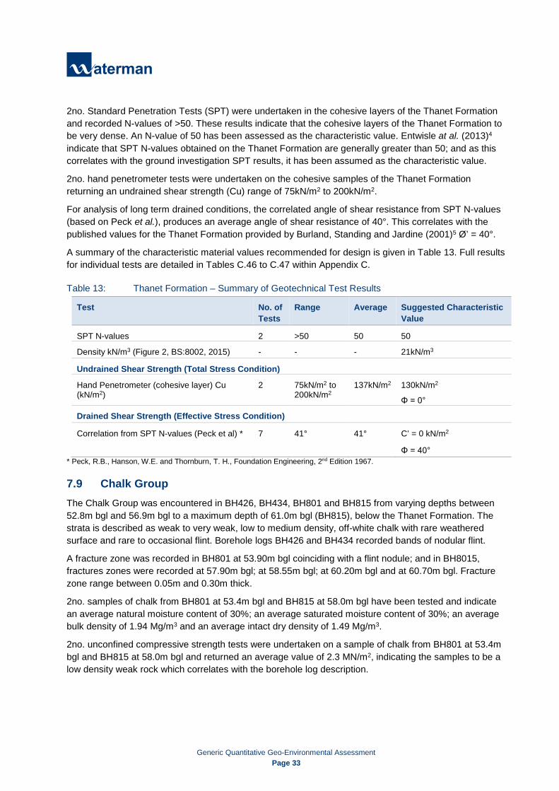
Generic Quantitative Geo-Environmental Assessment
Page 33
2no. Standard Penetration Tests (SPT) were undertaken in the cohesive layers of the Thanet Formation and recorded N-values of >50. These results indicate that the cohesive layers of the Thanet Formation to be very dense. An N-value of 50 has been assessed as the characteristic value. Entwisle at al. (2013)4 indicate that SPT N-values obtained on the Thanet Formation are generally greater than 50; and as this correlates with the ground investigation SPT results, it has been assumed as the characteristic value.
2no. hand penetrometer tests were undertaken on the cohesive samples of the Thanet Formation returning an undrained shear strength (Cu) range of 75kN/m2 to 200kN/m2.
For analysis of long term drained conditions, the correlated angle of shear resistance from SPT N-values (based on Peck et al.), produces an average angle of shear resistance of 40°. This correlates with the published values for the Thanet Formation provided by Burland, Standing and Jardine (2001)5 Ø’ = 40°.
A summary of the characteristic material values recommended for design is given in Table 13. Full results for individual tests are detailed in Tables C.46 to C.47 within Appendix C.
Table 13: Thanet Formation – Summary of Geotechnical Test Results
Test No. of Tests
Range Average Suggested Characteristic Value
SPT N-values 2 >50 50 50
Density kN/m3 (Figure 2, BS:8002, 2015) - - - 21kN/m3
Undrained Shear Strength (Total Stress Condition)
Hand Penetrometer (cohesive layer) Cu (kN/m2)
2 75kN/m2 to 200kN/m2
137kN/m2 130kN/m2
Φ = 0°
Drained Shear Strength (Effective Stress Condition)
Correlation from SPT N-values (Peck et al) * 7 41° 41° C’ = 0 kN/m2
Φ = 40° * Peck, R.B., Hanson, W.E. and Thornburn, T. H., Foundation Engineering, 2nd Edition 1967.
7.9 Chalk Group The Chalk Group was encountered in BH426, BH434, BH801 and BH815 from varying depths between 52.8m bgl and 56.9m bgl to a maximum depth of 61.0m bgl (BH815), below the Thanet Formation. The strata is described as weak to very weak, low to medium density, off-white chalk with rare weathered surface and rare to occasional flint. Borehole logs BH426 and BH434 recorded bands of nodular flint.
A fracture zone was recorded in BH801 at 53.90m bgl coinciding with a flint nodule; and in BH8015, fractures zones were recorded at 57.90m bgl; at 58.55m bgl; at 60.20m bgl and at 60.70m bgl. Fracture zone range between 0.05m and 0.30m thick.
2no. samples of chalk from BH801 at 53.4m bgl and BH815 at 58.0m bgl have been tested and indicate an average natural moisture content of 30%; an average saturated moisture content of 30%; an average bulk density of 1.94 Mg/m3 and an average intact dry density of 1.49 Mg/m3.
2no. unconfined compressive strength tests were undertaken on a sample of chalk from BH801 at 53.4m bgl and BH815 at 58.0m bgl and returned an average value of 2.3 MN/m2, indicating the samples to be a low density weak rock which correlates with the borehole log description.
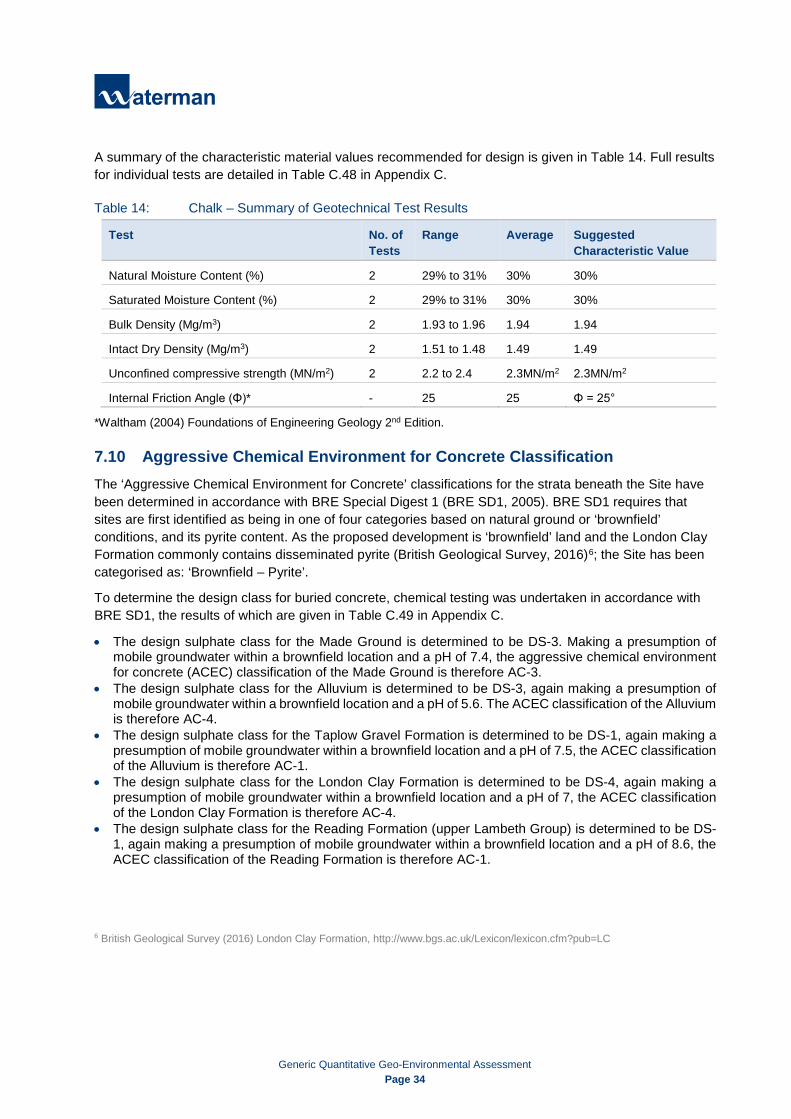
Generic Quantitative Geo-Environmental Assessment
Page 34
A summary of the characteristic material values recommended for design is given in Table 14. Full results for individual tests are detailed in Table C.48 in Appendix C.
Table 14: Chalk – Summary of Geotechnical Test Results
Test No. of Tests
Range Average Suggested Characteristic Value
Natural Moisture Content (%) 2 29% to 31% 30% 30%
Saturated Moisture Content (%) 2 29% to 31% 30% 30%
Bulk Density (Mg/m3) 2 1.93 to 1.96 1.94 1.94
Intact Dry Density (Mg/m3) 2 1.51 to 1.48 1.49 1.49
Unconfined compressive strength (MN/m2) 2 2.2 to 2.4 2.3MN/m2 2.3MN/m2
Internal Friction Angle (Φ)* - 25 25 Φ = 25°
*Waltham (2004) Foundations of Engineering Geology 2nd Edition.
7.10 Aggressive Chemical Environment for Concrete Classification The ‘Aggressive Chemical Environment for Concrete’ classifications for the strata beneath the Site have been determined in accordance with BRE Special Digest 1 (BRE SD1, 2005). BRE SD1 requires that sites are first identified as being in one of four categories based on natural ground or ‘brownfield’ conditions, and its pyrite content. As the proposed development is ‘brownfield’ land and the London Clay Formation commonly contains disseminated pyrite (British Geological Survey, 2016)6; the Site has been categorised as: ‘Brownfield – Pyrite’.
To determine the design class for buried concrete, chemical testing was undertaken in accordance with BRE SD1, the results of which are given in Table C.49 in Appendix C.
• The design sulphate class for the Made Ground is determined to be DS-3. Making a presumption of mobile groundwater within a brownfield location and a pH of 7.4, the aggressive chemical environment for concrete (ACEC) classification of the Made Ground is therefore AC-3.
• The design sulphate class for the Alluvium is determined to be DS-3, again making a presumption of mobile groundwater within a brownfield location and a pH of 5.6. The ACEC classification of the Alluvium is therefore AC-4.
• The design sulphate class for the Taplow Gravel Formation is determined to be DS-1, again making a presumption of mobile groundwater within a brownfield location and a pH of 7.5, the ACEC classification of the Alluvium is therefore AC-1.
• The design sulphate class for the London Clay Formation is determined to be DS-4, again making a presumption of mobile groundwater within a brownfield location and a pH of 7, the ACEC classification of the London Clay Formation is therefore AC-4.
• The design sulphate class for the Reading Formation (upper Lambeth Group) is determined to be DS-1, again making a presumption of mobile groundwater within a brownfield location and a pH of 8.6, the ACEC classification of the Reading Formation is therefore AC-1.
6 British Geological Survey (2016) London Clay Formation, http://www.bgs.ac.uk/Lexicon/lexicon.cfm?pub=LC

Generic Quantitative Geo-Environmental Assessment
Page 35
7.11 Groundwater, Permeability and Soils Infiltration
7.11.1 Groundwater Groundwater was encountered in a number of exploratory holes, detailed in Table C.50 in Appendix C.
Monitoring during the ground investigations recorded a minimum depth of 0.10mbgl (+41.80m OD) in BH433. The highest recorded groundwater was found in TP854 at a depth of 2.75m bgl (+44m OD). This groundwater was recorded within the Made Ground and is mostly likely to be ‘perched’, however, it should be noted that levels are likely to fluctuate dependent on season and prevailing weather conditions. Therefore, for design purposes it is recommended groundwater level be assumed at 0.50m bgl.
In accordance with BS:8102 (2009) the groundwater is considered ‘Variable’, when assessed in consideration of the ground floor slab having a finished floor level of +42.365m OD.
7.11.2 Permeability 16no. Falling Head tests were undertaken, detailed in Table C. 51 in Appendix C. The results indicate that tests undertaken in Made Ground returned permeability (k) range of 2.19x10⁻⁹m/s to 3.53x10⁻⁶m/s, the tests undertaken in Made Ground/Alluvium/London Clay Formation returned a k range of 5.72x10⁻⁹m/s to 2.94x10⁻⁵ m/s; and where the tests were undertaken in Alluvium only, the k range varies from 6.32x10⁻⁷ m/s to 6.13x10⁻⁶ m/s.
Permeability (kv) has also been derived from the oedometer test results which show a kv value range 2x10⁻⁸m/s to 3.5x10⁻⁶m/s within the London Clay Formation.
These results indicated that the tests undertaken in Made Ground; and Made Ground/Alluvium/London Clay Formation to range from practically impermeable to a low permeability. The Alluvium and London Clay Formation have a very low to low permeability, and the Taplow Gravel Formation has a low permeability (Carter and Bentley, 1991)7.
Typical values quoted for London Clay Formation range from 2.4x10⁻¹⁰m/s to 4.4x10⁻⁸m/s (CIRIA, 2004)8. Although the results sit beyond the range, this may be due to the secondary components of the clay tested.
7.11.3 Soil Infiltration 3no. soakaway tests were undertaken in accordance with BRE 365 was undertaken in Taplow Gravel Formation (very clayey gravel) in BH814 at 3.5m bgl and in the London Clay Formation in BH809 at 5.0m bgl (silty clay with occasional silt and sand partings); and WS806 at 3.0m bgl (slightly sandy silty clay with rare partings of sand).
The Taplow Gravel Formation results returned a value of 1.64x10⁻⁵m/sec indicating that this deposit may be suitable for a borehole soakaway, however it should be noted that the Taplow Gravel Formation deposit is sporadically located across the Site.
The London Clay Formation test results returned infiltration as ‘no significant fall after 75 mins’ with no estimate of infiltration provided and an infiltration rate of 1.17x10⁻⁶m/sec respectively, indicating the London Clay Formation would not be suitable for a borehole soakaway. It is recommended that consultation with a drainage engineer is undertaken.
7 Carter and Bentley, 1991, Correlations of Soil Properties, Pentech Press, London 8 CIRIA, 2004, Engineering in the Lambeth Group, London

Generic Quantitative Geo-Environmental Assessment
Page 36
8. Environmental Results Detailed logs of the strata encountered, together with records of the samples taken during both trial pitting and borehole installation and PID readings, are provided in the Soil Consultants Factual Report in Appendix B. A summary of the geological strata and manmade underground structures encountered is presented below.
8.1 Chemical Analysis The laboratory test results for soil and groundwater samples collected during the ground investigation works are presented in Appendix F.
No visual or olfactory evidence of soil or groundwater contamination was observed during the ground investigation or groundwater sampling.
8.2 Controlled Waters
8.2.1 Shallow Groundwater (Made Ground, Alluvium and Taplow Gravel Formation) Given the sporadic presence of the shallow natural strata (Alluvium and Taplow Gravel Formation), groundwater in these layers was not found at a consistent level across the Site. The most recent groundwater level monitoring (October to December 2016) recorded groundwater level in the shallow geology (Made Ground, Alluvium and Taplow Gravel) is generally +38 to +45m OD.
Groundwater monitoring found levels are relatively steady, with little variation over the monitoring period to date. Shallow groundwater levels in the northeast were found to be 5m to 6.5m higher than in the remainder of the Site area, which correlates with the topographic profile of the Site. Generally, the data collected indicated the shallow groundwater flow direction was towards the west, in general agreement with the southwest direction assessed by the 2015 Aecom study.
8.2.2 Deep Groundwater (Lambeth Group) Water levels recorded in the Lambeth Group Secondary A aquifer beneath the London Clay Formation rose above the screening sections of the wells, stabilising at +39m OD. This indicates the water body in the Lambeth Group is constrained beneath the London Clay Formation under sub-artesian pressure. Full groundwater monitoring results are detailed in Table 15.
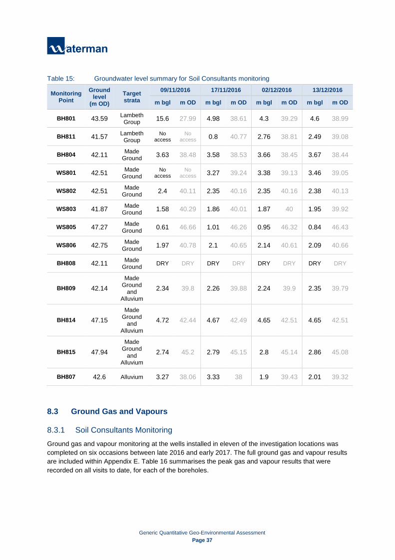
Generic Quantitative Geo-Environmental Assessment
Page 37
Table 15: Groundwater level summary for Soil Consultants monitoring
Monitoring Point
Ground level
(m OD) Target strata
09/11/2016 17/11/2016 02/12/2016 13/12/2016
m bgl m OD m bgl m OD m bgl m OD m bgl m OD
BH801 43.59 Lambeth Group 15.6 27.99 4.98 38.61 4.3 39.29 4.6 38.99
BH811 41.57 Lambeth Group
No access
No access 0.8 40.77 2.76 38.81 2.49 39.08
BH804 42.11 Made Ground 3.63 38.48 3.58 38.53 3.66 38.45 3.67 38.44
WS801 42.51 Made Ground
No access
No access 3.27 39.24 3.38 39.13 3.46 39.05
WS802 42.51 Made Ground 2.4 40.11 2.35 40.16 2.35 40.16 2.38 40.13
WS803 41.87 Made Ground 1.58 40.29 1.86 40.01 1.87 40 1.95 39.92
WS805 47.27 Made Ground 0.61 46.66 1.01 46.26 0.95 46.32 0.84 46.43
WS806 42.75 Made Ground 1.97 40.78 2.1 40.65 2.14 40.61 2.09 40.66
BH808 42.11 Made Ground DRY DRY DRY DRY DRY DRY DRY DRY
BH809 42.14 Made
Ground and
Alluvium 2.34 39.8 2.26 39.88 2.24 39.9 2.35 39.79
BH814 47.15 Made
Ground and
Alluvium
4.72 42.44 4.67 42.49 4.65 42.51 4.65 42.51
BH815 47.94 Made
Ground and
Alluvium 2.74 45.2 2.79 45.15 2.8 45.14 2.86 45.08
BH807 42.6 Alluvium 3.27 38.06 3.33 38 1.9 39.43 2.01 39.32
8.3 Ground Gas and Vapours
8.3.1 Soil Consultants Monitoring Ground gas and vapour monitoring at the wells installed in eleven of the investigation locations was completed on six occasions between late 2016 and early 2017. The full ground gas and vapour results are included within Appendix E. Table 16 summarises the peak gas and vapour results that were recorded on all visits to date, for each of the boreholes.

Generic Quantitative Geo-Environmental Assessment
Page 38
Table 16: Ground gas and vapour level summary for Soil Consultants monitoring
Monitoring Point
Peak Concentration Peak flow
(l/hour)
(% v/v) (%) (ppm)
Methane Carbon Dioxide
Oxygen (MIN)
Lower Explosive
Limit Hydrogen Sulphide
Carbon Monoxide Vapours
BH804 <0.01 2.50 12.90 <0.01 <0.01 <0.01 0.6 0.2
BH807 1.40 6.60 9.10 20.00 <0.01 1.00 0.6 0.3
BH808 0.70 3.40 0.60 14.00 <0.01 <0.01 0.7 0.2
BH809 <0.01 0.90 13.80 <0.01 <0.01 <0.01 0.2 0.3
BH814 <0.01 4.80 0.80 <0.01 <0.01 <0.01 0.8 0.2
BH815 0.10 0.80 0.30 <0.01 1.00 53.00 9.6 0.1
WS801 21.60 6.70 0.40 <0.01 <0.01 <0.01 0.7 0.2
WS802 <0.01 2.80 15.80 <0.01 <0.01 <0.01 0.1 0.3
WS803 0.10 1.30 1.20 <0.01 <0.01 <0.01 0.4 0.2
WS805 1.50 5.00 0.30 30.00 <0.01 <0.01 0.8 0.2
WS806 <0.01 3.10 16.90 <0.01 <0.01 <0.01 0.2 0.3
8.3.2 Structural Soils Monitoring Structural Soils completed ground gas monitoring in three of the exploratory holes with in the Site boundary in 2006. Further ground gas monitoring was completed in 33no. exploratory holes in the south of the Site in 2015. The full ground gas and vapour results are included within Appendix E. Table 17 summarises the peak gas results that were recorded on all visits, for each of the boreholes.
Table 17: Ground gas and vapour level summary for Structural Soils monitoring
Monitoring Point
Peak Concentration Peak flow
(l/hour)
(% v/v) (%)
Methane Carbon Dioxide Oxygen (MIN) Lower Explosive Limit
2015 monitoring
WS601 <0.1 6.3 11.9 <0.1 0.4
WS679 <0.1 1.5 19.3 <0.1 <0.1
WS681 1.2 3.4 4 29.2 <0.1
WS689A <0.1 0.2 19.9 <0.1 <0.1
WS690 <0.1 0.7 17.2 <0.1 <0.1
WS6114 <0.1 0.5 19.3 <0.1 0.4 WS645 <0.1 8.8 3.8 <0.1 <0.1

Generic Quantitative Geo-Environmental Assessment
Page 39
Monitoring Point
Peak Concentration Peak flow
(l/hour)
(% v/v) (%)
Methane Carbon Dioxide Oxygen (MIN) Lower Explosive Limit
BH404 <0.1 0.1 20.2 <0.1 <0.1 BH406A <0.1 1.7 20.1 <0.1 <0.1 BH469 <0.1 0.9 19.8 <0.1 <0.1 BH470 <0.1 0.4 19.8 <0.1 <0.1 BH469 <0.1 0.9 19.7 <0.1 <0.1
BH470 <0.1 0.4 19.7 <0.1 <0.1
BH487 (WS692) <0.1 0.3 19.6 <0.1 <0.1
BH412 <0.1 0.4 20 <0.1 <0.1
BH415 <0.1 0.2 18.1 <0.1 <0.1
BH417A <0.1 0.6 20.3 <0.1 <0.1
BH419 <0.1 1.2 18 <0.1 <0.1
BH421 <0.1 4.5 7.4 <0.1 <0.1
BH422 <0.1 3.2 20 <0.1 <0.1
BH461 <0.1 1.2 19.6 <0.1 <0.1
BH462 <0.1 4.3 0 <0.1 <0.1
BH463 <0.1 1 19.3 <0.1 <0.1
BH481 <0.1 8.5 8.2 <0.1 <0.1
BH430 <0.1 5.7 <0.1 <0.1 <0.1
BH434 <0.1 0.9 19.1 <0.1 <0.1
BH435 <0.1 0.2 19.5 <0.1 <0.1
BH479 <0.1 0.5 20.3 <0.1 <0.1
BH480 <0.1 0.7 17.8 <0.1 <0.1
BH438A 1.2 2.3 15.1 <0.1 <0.1
BH439B <0.1 0.2 20.1 <0.1 0.4
BH443 <0.1 1.2 13.8 <0.1 0.4
BH473 <0.1 5.1 19.1 <0.1 <0.1
2006 monitoring
SS02/BH106 0.2 3.6 3.7 <0.1 -0.5 SS02/BH105 0.3 9.8 6.6 <0.1 0.3 SS02/BH104 0.3 0.7 19.7 <0.1 -1.1

Generic Quantitative Geo-Environmental Assessment
Page 40
9. Generic Assessment Criteria The information requirements for generic quantitative risk assessment will depend on:
The substance being assessed;
The receptors being considered;
The pathways being considered; and
The complexity of the assessed area.
The outline conceptual model developed for the Site has identified potential pollutant linkages between contamination sources, and current and future receptors. These linkages have been investigated and the results assessed against generic assessment criteria. The generic assessment criteria selected for each potential pollutant linkage are summarised in Table 18.
Table 18: Generic assessment criteria Source Pathway Receptor Generic Assessment Criteria
Contamination in Made Ground and shallow soils from on-Site and adjacent off-Site land uses
Dermal contact and ingestion of contaminated soils. Ingestion of contamination via plant uptake in private gardens
Future users of the proposed development
River Brent Infilling Works and Brent Cross Shopping Centre remediation zones
Waterman Generic Assessment Criteria for land with a commercial end-use, and 1% soil organic matter
Sturgess Park remediation zone
Waterman Generic Assessment Criteria for public open spaces, and 2.5% soil organic matter
Plot 113 remediation zone
Waterman Generic Assessment Criteria for land with a residential end-use, and 1% soil organic matter
Construction workers Qualitative assessment
Contaminated groundwater in the Made Ground, Alluvium, and Taplow Gravel Formation
Lateral migration off-Site and vertical migration to deeper aquifers
Off-Site receptors
Waterman Generic Assessment Criteria for the general quality of a groundwater body
Direct Contact
New water supply pipes
UKWIR Guidance for the Selection of Water Supply Pipes to be used in Brownfield Sites
Buried structures BRE Special Digest 1 (2005): 3rd Edition guidance
Ground gas arising from Made Ground and Alluvium and vapours from hydrocarbon contamination
Accumulation in confined spaces, leading to inhalation followed by asphyxiation and risk of explosion
Future users of the proposed development
Gas Screening Value determination and assessment in accordance with CIRIA C665 Quantitative assessment for vapours in accordance with CIRIA C682
The generic assessment criteria used in this report are further detailed in Appendix J.

Generic Quantitative Geo-Environmental Assessment
Page 41
10. Quantitative Environmental Risk Assessment The potential pollutant linkages identified in Section 3.2 have been evaluated using the Generic Assessment Criteria described in Section 9 and Appendix J. The results of the Soil Consultants 2016 investigation, along with the findings of the previous intrusive ground investigations undertaken at the Site between 2006 and 2014 by Structural Soils have been considered.
The investigation locations within each specific plot at the four remediation zones are outlined in Table 19.
Table 19: Investigation locations at each plot
Remediation Zone
Plot Number Investigation locations relevant to this Zone with contaminant exceedances
River Brent Infilling Works
K16 None identified
K39 Structural Soils: BH435, BH465, BH465A, SS02/WS255 K40 Structural Soils: BH469, CPT726 K41 Structural Soils: BH467, CPT725, SS02/WS254
Brent Cross Shopping Centre Extension
101 Structural Soils: CPT71, TP584, TP519, TP563, TP520, TP584, BH434, BH434A, BH463, BH454, BH454A, BH429, BH429A, BH430, S02/WS243 Soil Consultants: BH807
102 Structural Soils: CPT714, TP515, WS681, BH433, BH462, BH428, BH426 Soil Consultants: BH809, WS803
103 Structural Soils: CPT170, BH414
104 Structural Soils: CPT724, WS601, WS686A, TP505, TP506, BH413, BH472, SS02/BH104, SS02/WS249
105 Structural Soils: WS690, WS691, WS689, WS689A, TP503, BH412, BH470, BH464, BH565, BH487 Soil Consultants: BH813, BH814, BH815, WS805
106 Structural Soils: WS685 Soil Consultants: BH811
107 Structural Soils: WS678, TP549, SS02/WS202
108 Structural Soils: BH481 Soil Consultants: BH808
109 Structural Soils: BH479, WS679, SS02/WS202A Soil Consultants: BH803, BH804, BH805, WS804
110 Structural Soils: WS677, WS677A, TP566
111 Structural Soils: TP551, SS02/WS258 Soil Consultants: WS806
112 None identified
K20 Structural Soils: CPT709, BH420, BH420A, BH415, BH419, BH418, BH418A, BH417, BH417A, BH461
K30 Structural Soils: WS684, BH480, SS02/WS257 Soil Consultants: BH810
K31 Structural Soils: BH423, Soil Consultants: WS801, WS802

Generic Quantitative Geo-Environmental Assessment
Page 42
Remediation Zone
Plot Number Investigation locations relevant to this Zone with contaminant exceedances
K35 Structural Soils: WS676, TP550 Soil Consultants; BH801
K37 Structural Soils: WS686, SS02/WS256, SS02/WS256A
K38 Structural Soils: WS427, WS682, WS687, WS687A, TP510, TP512, TP514, BH425, BH424, BH424A, BH421, BH422, BH416, SS02/WS248, SS02/WS248A
K48 Structural Soils: WS688, SS02/BH106, SS02/BH105 Soil Consultants: BH806, BH812
Sturgess Park K36 Structural Soils: WS6107, WS6108, WS6109, WS6110
Plot 113 113 Structural Soils: WS1001, WS1002, BH2001, SS02/WS259
10.1 Risk to Human Health The relevant human health receptors within the four remediation zones vary depending on the proposed end-use. Therefore, each remediation zone has been considered separately.
Soil samples collected across the total Site area by Structural Soils and Soil Consultants from the Made Ground and shallow soils were tested for a range of organic and inorganic contaminants including metals, total petroleum hydrocarbons (TPH), benzene, toluene, ethylbenzene and xylene (BTEX), polyaromatic hydrocarbons (PAH), phenols, volatile organic compounds (VOCs) and semi-volatile organic compounds (SVOCs).
Samples collected from the Made Ground by all investigations were also tested for asbestos, with identification and quantification of any asbestos or asbestos containing materials detected.
Soil contamination levels identified in samples above the GAC applied to each remediation zone are outlined in the Ground Contamination Exceedances Plan in Figure A4 of Appendix A.
10.1.1 Brent Cross Shopping Centre Expansion The proposed end-use for the expanded Brent Cross Shopping Centre (including the land above the infilled River Brent) is commercial in nature. The proposed basement will excavate material in the southern area.
The laboratory results for soil samples from the previous investigations by Structural Soils and Soil Consultants have been compared against Waterman’s Generic Assessment Criteria for land with a commercial end-use. The organic content of soil samples from these investigations ranged between 0.21% and 16.2%, with an average of 2.02%. Therefore, the commercial GAC for soils with 1% soil organic matter have been chosen to provide the most conservative assessment of the Site as a whole.
Organic and inorganic contamination
The organic and inorganic contamination exceedances for each individual development plot are reproduced in Table 20. Where plots are not listed, no contamination exceedances were identified.
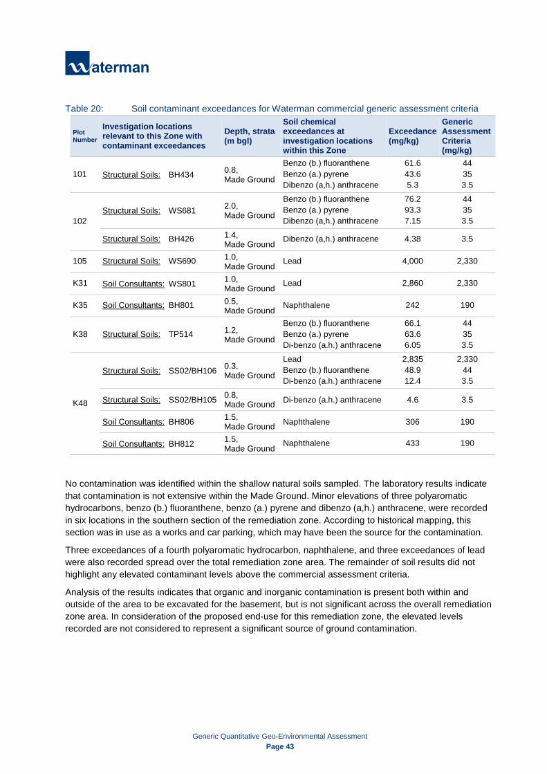
Generic Quantitative Geo-Environmental Assessment
Page 43
Table 20: Soil contaminant exceedances for Waterman commercial generic assessment criteria
Plot Number
Investigation locations relevant to this Zone with contaminant exceedances
Depth, strata (m bgl)
Soil chemical exceedances at investigation locations within this Zone
Exceedance (mg/kg)
Generic Assessment Criteria (mg/kg)
101 Structural Soils: BH434 0.8, Made Ground
Benzo (b.) fluoranthene Benzo (a.) pyrene Dibenzo (a,h.) anthracene
61.6 43.6 5.3
44 35 3.5
102 Structural Soils: WS681 2.0,
Made Ground
Benzo (b.) fluoranthene Benzo (a.) pyrene Dibenzo (a,h.) anthracene
76.2 93.3 7.15
44 35 3.5
Structural Soils: BH426 1.4, Made Ground Dibenzo (a,h.) anthracene 4.38 3.5
105 Structural Soils: WS690 1.0, Made Ground Lead 4,000 2,330
K31 Soil Consultants: WS801 1.0, Made Ground Lead 2,860 2,330
K35 Soil Consultants: BH801 0.5, Made Ground Naphthalene 242 190
K38 Structural Soils: TP514 1.2, Made Ground
Benzo (b.) fluoranthene Benzo (a.) pyrene Di-benzo (a.h.) anthracene
66.1 63.6 6.05
44 35 3.5
K48
Structural Soils: SS02/BH106 0.3, Made Ground
Lead Benzo (b.) fluoranthene Di-benzo (a.h.) anthracene
2,835 48.9 12.4
2,330 44 3.5
Structural Soils: SS02/BH105 0.8, Made Ground Di-benzo (a.h.) anthracene 4.6 3.5
Soil Consultants: BH806 1.5, Made Ground Naphthalene 306 190
Soil Consultants: BH812 1.5, Made Ground Naphthalene 433 190
No contamination was identified within the shallow natural soils sampled. The laboratory results indicate that contamination is not extensive within the Made Ground. Minor elevations of three polyaromatic hydrocarbons, benzo (b.) fluoranthene, benzo (a.) pyrene and dibenzo (a,h.) anthracene, were recorded in six locations in the southern section of the remediation zone. According to historical mapping, this section was in use as a works and car parking, which may have been the source for the contamination.
Three exceedances of a fourth polyaromatic hydrocarbon, naphthalene, and three exceedances of lead were also recorded spread over the total remediation zone area. The remainder of soil results did not highlight any elevated contaminant levels above the commercial assessment criteria.
Analysis of the results indicates that organic and inorganic contamination is present both within and outside of the area to be excavated for the basement, but is not significant across the overall remediation zone area. In consideration of the proposed end-use for this remediation zone, the elevated levels recorded are not considered to represent a significant source of ground contamination.
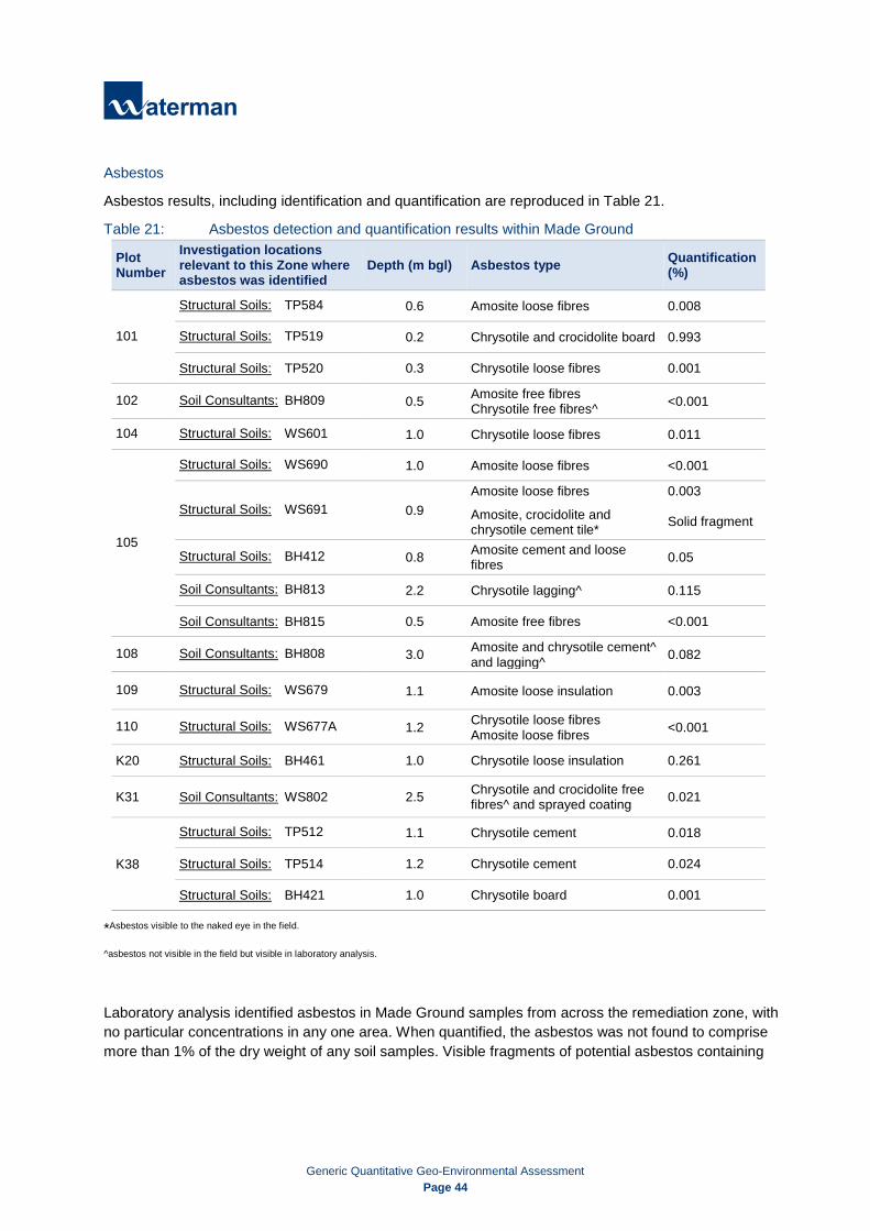
Generic Quantitative Geo-Environmental Assessment
Page 44
Asbestos
Asbestos results, including identification and quantification are reproduced in Table 21.
Table 21: Asbestos detection and quantification results within Made Ground
Plot Number
Investigation locations relevant to this Zone where asbestos was identified
Depth (m bgl) Asbestos type Quantification (%)
101
Structural Soils: TP584 0.6 Amosite loose fibres 0.008
Structural Soils: TP519 0.2 Chrysotile and crocidolite board 0.993
Structural Soils: TP520 0.3 Chrysotile loose fibres 0.001
102 Soil Consultants: BH809 0.5 Amosite free fibres Chrysotile free fibres^ <0.001
104 Structural Soils: WS601 1.0 Chrysotile loose fibres 0.011
105
Structural Soils: WS690 1.0 Amosite loose fibres <0.001
Structural Soils: WS691 0.9 Amosite loose fibres
Amosite, crocidolite and chrysotile cement tile*
0.003 Solid fragment
Structural Soils: BH412 0.8 Amosite cement and loose fibres 0.05
Soil Consultants: BH813 2.2 Chrysotile lagging^ 0.115
Soil Consultants: BH815 0.5 Amosite free fibres <0.001
108 Soil Consultants: BH808 3.0 Amosite and chrysotile cement^ and lagging^ 0.082
109 Structural Soils: WS679 1.1 Amosite loose insulation 0.003
110 Structural Soils: WS677A 1.2 Chrysotile loose fibres Amosite loose fibres <0.001
K20 Structural Soils: BH461 1.0 Chrysotile loose insulation 0.261
K31 Soil Consultants: WS802 2.5 Chrysotile and crocidolite free fibres^ and sprayed coating 0.021
K38
Structural Soils: TP512 1.1 Chrysotile cement 0.018
Structural Soils: TP514 1.2 Chrysotile cement 0.024
Structural Soils: BH421 1.0 Chrysotile board 0.001
*Asbestos visible to the naked eye in the field.
^asbestos not visible in the field but visible in laboratory analysis.
Laboratory analysis identified asbestos in Made Ground samples from across the remediation zone, with no particular concentrations in any one area. When quantified, the asbestos was not found to comprise more than 1% of the dry weight of any soil samples. Visible fragments of potential asbestos containing
Generic Quantitative Geo-Environmental Assessment
Page 45
materials were identified during field work in a sample from WS691, and by the laboratory at the sample analysis stage in BH809, BH813, BH808 and WS802. The remainder of asbestos detections were only visible under microscope examination.
The ground investigations found that Made Ground across the Site contained evidence of demolition material such as brick, concrete rubble, glass and wood which is likely also to have been the source of the asbestos identified.
Conclusions
Development works at the Brent Cross Shopping Centre expansion such as excavation of basements, foundation piling and levelling of the Site area will remove a large volume of potentially contaminated surface material. Once construction works are complete, the Site will be entirely covered by buildings, hardstanding and soft landscaping which will provide a barrier between future Site users and existing ground contamination. Therefore, at this remediation zone the risk to future Site users from ground contamination is considered to be low.
10.1.2 River Brent Infilling Works Within the Site boundary, the River Brent Works will involve infilling about a 450m length of the channel, which will then be overlain by the expanded Brent Cross Shopping Centre. Infilling of the river will present an option for placement of some of the arisings generated on-Site. Based on approximate measurements for the river channel at about 450m in length, 10m in width, and 1.5m deep. The total volume of material which could be placed is estimated at 6,750m3. Infilling of the embankments surrounding the river to raise the ground level are expected to allow for placement of a further 26,325m3, giving a total of 33,075m3.
The River Brent is presently a fully canalised, concrete lined waterway. Based on ground investigation logs for boreholes adjacent to the river, it is likely to be founded in Alluvium, above the London Clay Formation. This is likely to present a barrier between any material disposed directly within it and the surrounding natural strata. However, outside of the river infilling of the embankments could result in potentially contaminative material in contact with natural soils.
At the surface, the structures and hardstanding of the Brent Cross Shopping Centre above the infilled River Brent will break pathways between the infill material and future Site users.
The Made Ground at the Site has been found to contain some elevated levels of polyaromatic hydrocarbons and metals. Asbestos has also been identified in numerous samples. Beneath the Made Ground, no elevated levels of contamination were identified in the natural material (Alluvium, Taplow Gravel Formation and London Clay Formation). The selection of material for placement would be subject to it being chemically and geotechnically suitable.
10.1.3 Sturgess Park The majority of Sturgess Park is currently covered by managed grasslands, with some hardstanding pathways and a small tarmac play court. Development works at this remediation zone involves re-landscaping the parklands. The organic content of shallow soil samples from this area of the Site varies between 1.6% and 8.6%, with an average of 5.35%. Therefore, contamination results have been compared against GAC for a public open space, and 2.5% soil organic matter.
Results of this analysis found no exceedances for any organic or inorganic contaminants in any of the samples within this remediation zone. Asbestos was not detected in any of the samples.

Generic Quantitative Geo-Environmental Assessment
Page 46
As no contamination has been identified in the shallow soils, the completed development works at this remediation zone are not considered to pose a significant risk to future Site users.
Additional topsoil may need to be imported to the Site to re-landscape the parklands. Any materials brought on-Site for this purpose should be confirmed as clean and uncontaminated to ensure the risk of future Site users contacting ground contamination remains low.
10.1.4 Plot 113 Current proposals involve the construction of mid-rise buildings at Plot 113, with a residential end-use. Soft landscaping will be present, however private gardens with the potential for plant uptake are not anticipated. Therefore, contamination results for this remediation zone have been compared against GAC for land with a residential end-use, without plant uptake by residents. The organic content of soils varied between 0.6% and 1.5%, and therefore a GAC soil organic matter bracket of 1% was used.
Results of this analysis found a single exceedance of lead contamination, and an exceedance of benzo (a.h.) anthracene above the applied GAC within this remediation zone.
Table 22: Soil contaminant exceedances for Waterman commercial generic assessment criteria
Plot Number
Investigation locations relevant to this Zone with contaminant exceedances
Depth, strata (m bgl)
Soil chemical exceedances at investigation locations within this Zone
Exceedance (mg/kg)
Generic Assessment Criteria (mg/kg)
113 Structural Soils: SS02/WS259 0.45, Made Ground
Lead Dibenzo (a.h.) anthracene
4157 0.33
310 0.31
Asbestos was detected in a single sample, detailed in Table 23.
Table 23: Asbestos detection and quantification results within Made Ground
Plot Number
Investigation locations relevant to this Zone where asbestos was identified
Asbestos type Quantification (%)
113 Structural Soils: BH2001 Chrysotile loose fibres <0.001
Conclusions
As with other remediation zones, once construction works at Plot 113 are complete it will be entirely covered by buildings, hardstanding and soft landscaping. This will prevent future Site users contacting existing ground contamination. Therefore, at this remediation zone the risk to future Site users from ground contamination is considered to be low.
Plot 113 is currently entirely covered by hardstanding, and therefore soils will need to be imported to this zone in order to construct the proposed soft landscaping. These soils should be confirmed as clean and uncontaminated to ensure the risk of future Site users contacting ground contamination remains low.
10.2 Risk to Controlled Waters The completed development will be entirely covered by structures, hardstanding and soft landscaping. There are no groundwater abstractions present within 250m of the Site boundary. Therefore, no current or future human health receptors for groundwater have been identified.
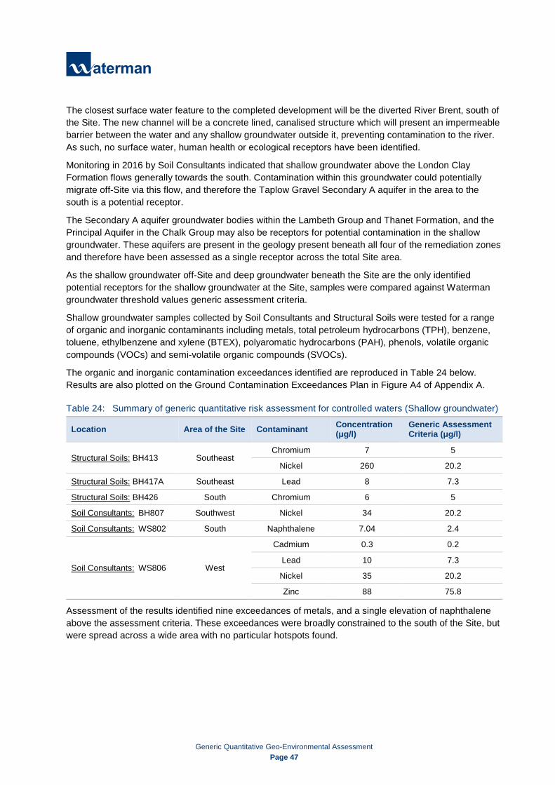
Generic Quantitative Geo-Environmental Assessment
Page 47
The closest surface water feature to the completed development will be the diverted River Brent, south of the Site. The new channel will be a concrete lined, canalised structure which will present an impermeable barrier between the water and any shallow groundwater outside it, preventing contamination to the river. As such, no surface water, human health or ecological receptors have been identified.
Monitoring in 2016 by Soil Consultants indicated that shallow groundwater above the London Clay Formation flows generally towards the south. Contamination within this groundwater could potentially migrate off-Site via this flow, and therefore the Taplow Gravel Secondary A aquifer in the area to the south is a potential receptor.
The Secondary A aquifer groundwater bodies within the Lambeth Group and Thanet Formation, and the Principal Aquifer in the Chalk Group may also be receptors for potential contamination in the shallow groundwater. These aquifers are present in the geology present beneath all four of the remediation zones and therefore have been assessed as a single receptor across the total Site area.
As the shallow groundwater off-Site and deep groundwater beneath the Site are the only identified potential receptors for the shallow groundwater at the Site, samples were compared against Waterman groundwater threshold values generic assessment criteria.
Shallow groundwater samples collected by Soil Consultants and Structural Soils were tested for a range of organic and inorganic contaminants including metals, total petroleum hydrocarbons (TPH), benzene, toluene, ethylbenzene and xylene (BTEX), polyaromatic hydrocarbons (PAH), phenols, volatile organic compounds (VOCs) and semi-volatile organic compounds (SVOCs).
The organic and inorganic contamination exceedances identified are reproduced in Table 24 below. Results are also plotted on the Ground Contamination Exceedances Plan in Figure A4 of Appendix A.
Table 24: Summary of generic quantitative risk assessment for controlled waters (Shallow groundwater)
Location Area of the Site Contaminant Concentration (μg/l)
Generic Assessment Criteria (μg/l)
Structural Soils: BH413 Southeast Chromium 7 5
Nickel 260 20.2
Structural Soils: BH417A Southeast Lead 8 7.3
Structural Soils: BH426 South Chromium 6 5
Soil Consultants: BH807 Southwest Nickel 34 20.2
Soil Consultants: WS802 South Naphthalene 7.04 2.4
Soil Consultants: WS806 West
Cadmium 0.3 0.2
Lead 10 7.3
Nickel 35 20.2
Zinc 88 75.8
Assessment of the results identified nine exceedances of metals, and a single elevation of naphthalene above the assessment criteria. These exceedances were broadly constrained to the south of the Site, but were spread across a wide area with no particular hotspots found.

Generic Quantitative Geo-Environmental Assessment
Page 48
In all instances where contamination was identified, the elevated level was only slightly above the assessment criteria with the exception of nickel levels at BH413, which was recorded at 260μg/l. This suggests the overall groundwater body has not been significantly impacted by ground contamination.
Conclusions
Historically, the area surrounding the Site has supported similar industrial uses to the Site itself. As such, shallow groundwater is likely to have been impacted by contamination and therefore will not be further impacted by migration of shallow groundwater from the Site. A significant area of land surrounding the Site is already covered by hardstanding, or is proposed to be redeveloped, which is likely to prevent future off-Site users contacting shallow groundwater.
Ground investigation found the Site is underlain by about 28-35m of London Clay Formation, which should present an impermeable barrier for the migration of contaminants to the deep Secondary A and Principal Aquifers. Foundations for the proposed development are anticipated to comprise this layer.
A Foundation Works Risk Assessment should be undertaken for the Site. This will inform the most appropriate design for piled foundations, to prevent downward migration of potentially contaminated shallow groundwater from the Made Ground, Alluvium or Taplow Gravel Formation. The Foundation Works Risk Assessment should also take into consideration that the groundwater in the Lambeth Group is under sub-artesian pressure.
10.3 Risk posed by Ground Gas and Vapours
10.3.1 Ground Gas Structural Soils undertook three rounds of ground gas monitoring at monitoring wells across the Site in 2006, and six further rounds in 2015. Soil Consultants undertook six rounds of ground gas and vapour monitoring at the Site between late 2016 and early 2017. Across the majority of the Site, methane concentrations were not recorded above the limit of detection for the equipment by either investigation (<0.1% v/v). However, at a single Soil Consultants location, WS801 in the northwest of the Site a consistently elevated presence of methane was detected, between 19.1% v/v up to 21.6% v/v. Carbon dioxide levels were recorded above the limit of detection in both Soil Consultants and Structural Soils boreholes, between 0.8% v/v and 6.7% v/v. Depleted oxygen levels were found, down to a minimum of <0.1% v/v. A maximum outflow rate of +0.3l/hour was recorded by Soil Consultants, and +0.4l/hour by Structural Soils.
To assess the likely risk posed by ground gases a preliminary gas screening value (GSV) is calculated using the recorded gas flow (l/hr) and the maximum gas concentration (%), outlined below.
GSV = (Measured Maximum CO2 or CH4 Gas Concentration (%)) ×
Maximum Measured Gas Flow Rate from boreholes (l/hr) 100
GSVs are calculated using the highest value of carbon dioxide or methane recorded during monitoring, with the result compared against the characteristic situations described within CIRIA C665, presented in Appendix J.

Generic Quantitative Geo-Environmental Assessment
Page 49
Based on the highest methane concentration recorded of 21.6% v/v and the peak flow rate of +0.4 l/hr, the GSV for the Site is calculated as 0.086. However, this is calculated based on the overall highest methane reading which was only encountered in a single monitoring location, WS801 in the south west of the Site. Nearby monitoring wells WS804, BH808, WS802 and WS803 did not find elevated methane levels, suggesting the ground gas source was localised within the Made Ground in this area, rather than representative of the overall Site.
Based on this GSV, the Site is categorised as a “Characteristic Situation 2 (CS2)” according to the modified Wilson and Card Classification System. The CS2 characterisation is designated “Low Risk”, with basic ground gas protection measures recommended.
Borehole logs for WS801 indicate the Made Ground is 4.6m thick in this part of the Site, underlain by at least 2m of Alluvium. This material will be excavated as part of the basement in this area of the Site, which is likely to remove the potential source of the gas readings. However, the proposed basement will likely require basic gas protection measures.
As it is not considered to be representative of the overall Site area, this elevated methane reading has not been considered in the overall gas assessment for the Site. When the results of gas monitoring are reassessed using the next highest gas reading of 6.7% v/v carbon dioxide, the preliminary GSV for the Site is calculated as 0.027.
Based on this GSV, the Site is categorised as a “Characteristic Situation 1 (CS1)” according to the modified Wilson and Card Classification System. The CS1 characterisation is designated “Very Low Risk”, with no requirement for ground gas protection measures.
10.3.2 Vapours Soil arisings at the investigation locations were screened for vapours with a PID during ground investigation works. Concentrations of 4.9ppm and 4.4ppm were recorded in the Made Ground at WS801 in the south of the Site, and elevated vapour readings of 4.9ppm and 3.1ppm were also encountered in the Made Ground at WS802 nearby. An isolated elevated reading of 4.2ppm was collected at BH808, just north of this area. The remainder of readings were below 1ppm, with many below the limit of detection entirely.
Laboratory analysis found elevated readings of naphthalene in three soil samples, and one water sample collected from locations across the Site. For the remainder of soil samples and water samples the results of testing for hydrocarbon contamination were below the GAC, and in almost all examples were below the limit of detection. Although naphthalene is volatile and can act as a vapour source in high concentrations, the levels encountered were spread across the Site area rather than centred around a single point.
Follow-up hydrocarbon vapour monitoring was carried out in the monitoring wells using a PID. Low-level vapour concentrations were recorded above the limit of detection in ten of the eleven monitoring wells, below 1ppm. At one location, BH815 in the north-eastern corner of the Site readings were found to be consistently higher, between 6.5ppm and 9.6ppm.
Of the four incidents of elevated naphthalene, one was recorded within groundwater at WS802 which is an area of the Site to be excavated for the basement. The excavation and dewatering for this basement will remove the source material, mitigating the vapour risk. The second exceedance, recorded in soils at BH801 is in an area which will be overlain by a multi-storey car park, where ventilation will be sufficient to prevent vapour accumulation.

Generic Quantitative Geo-Environmental Assessment
Page 50
The remaining two exceedances, recorded at BH806 and BH812 are both in areas which will be overlain with the proposed development. Records for the borehole excavation in these two areas did not find material that could be acting as a vapour source, although some ash and clinker was noted. During excavation, no visual or olfactory evidence for hydrocarbon contamination was observed. Furthermore, in both instances the naphthalene exceedances were from samples collected at 1.5m bgl, and where the proposed development involves raising the ground level by a further 0.7m to 1.1m. Therefore, this is considered to break the potential pathways between any vapour generation and future Site users and structures.
Vapour monitoring during the ground investigation works and follow-up monitoring at the installed wells did not indicate widespread contamination present beneath the Site with the potential to give rise to vapours. Therefore, vapour ingress arising from soils or groundwater beneath the Site is not considered a significant risk across the overall Site.
10.4 Risks to Construction Workers from Ground Contamination A qualitative assessment of the risk to construction workers has been undertaken as part of this investigation, given that there are no specific GAC currently available for contamination risks to this receptor.
Sampling and laboratory testing of the Made Ground beneath the Site detected the presence of chrysotile asbestos as fibre bundles, and amosite as free fibres, fibre bundles and asbestos cement debris. However, subsequent quantification found the maximum percentage of asbestos detected in any sample was less than 0.261% of the total mass.
All works at the Site should be undertaken in accordance with the Control of Asbestos Regulations 2012. An Asbestos Management Plan (AMP) will be prepared for the Site, to include plans for managing asbestos both in structures to be demolished or modified, and within the Made Ground.
Construction workers would be subject to mandatory health and safety requirements under the Health and Safety at Work Act 1974, Construction (Design and Management) (CDM) Regulations 2015 and the Control of Substances Hazardous to Health (COSHH). These requirements include the use of regulation PPE and RPE should be used where there is a risk of exposure to potentially contaminated soils, dust and groundwater.
Slightly elevated concentrations of methane and carbon dioxide, and reduced oxygen levels have been recorded during ground gas and vapour monitoring. All ground works should be carried out in line with the Confined Space Regulations 1997.
10.5 Risk to Ecological Systems/Vegetation The Site is currently completely covered by hardstanding, with no soft landscaping present. Topsoil will need to be imported onto the Site to construct the proposed areas of soft landscaping and gardens. This will prevent vegetation coming into contact with any ground contamination.
10.6 Risk to Water Supply Pipes The UKWIR project steering group decided that barrier pipes would provide sufficient protection for the supply of drinking water in all Brownfield site conditions. However, this approach needs to be agreed with the local water company.
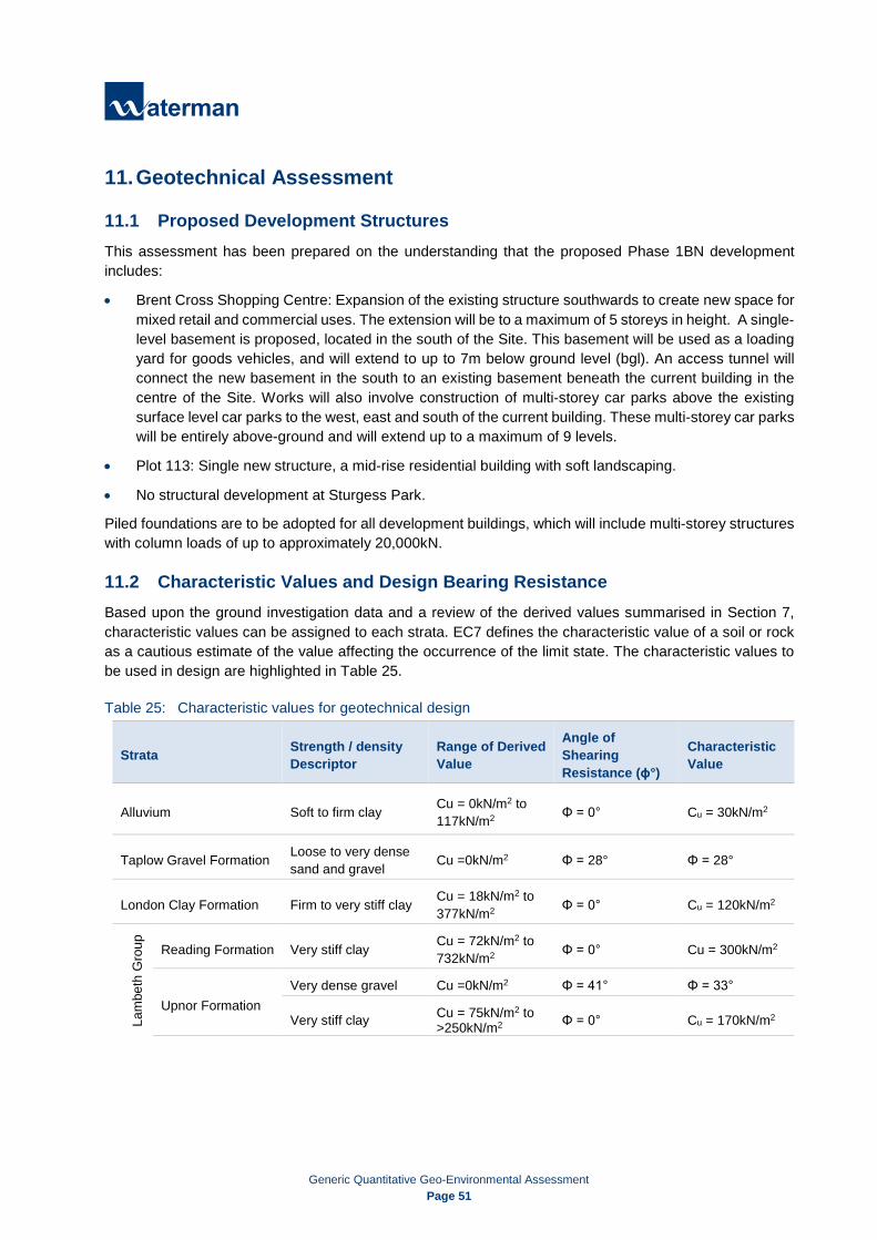
Generic Quantitative Geo-Environmental Assessment
Page 51
11. Geotechnical Assessment
11.1 Proposed Development Structures This assessment has been prepared on the understanding that the proposed Phase 1BN development includes:
• Brent Cross Shopping Centre: Expansion of the existing structure southwards to create new space for mixed retail and commercial uses. The extension will be to a maximum of 5 storeys in height. A single-level basement is proposed, located in the south of the Site. This basement will be used as a loading yard for goods vehicles, and will extend to up to 7m below ground level (bgl). An access tunnel will connect the new basement in the south to an existing basement beneath the current building in the centre of the Site. Works will also involve construction of multi-storey car parks above the existing surface level car parks to the west, east and south of the current building. These multi-storey car parks will be entirely above-ground and will extend up to a maximum of 9 levels.
• Plot 113: Single new structure, a mid-rise residential building with soft landscaping.
• No structural development at Sturgess Park.
Piled foundations are to be adopted for all development buildings, which will include multi-storey structures with column loads of up to approximately 20,000kN.
11.2 Characteristic Values and Design Bearing Resistance Based upon the ground investigation data and a review of the derived values summarised in Section 7, characteristic values can be assigned to each strata. EC7 defines the characteristic value of a soil or rock as a cautious estimate of the value affecting the occurrence of the limit state. The characteristic values to be used in design are highlighted in Table 25.
Table 25: Characteristic values for geotechnical design
Strata Strength / density Descriptor
Range of Derived Value
Angle of Shearing Resistance (ɸ°)
Characteristic Value
Alluvium Soft to firm clay Cu = 0kN/m2 to 117kN/m2 Φ = 0° Cu = 30kN/m2
Taplow Gravel Formation Loose to very dense sand and gravel Cu =0kN/m2 Φ = 28° Φ = 28°
London Clay Formation Firm to very stiff clay Cu = 18kN/m2 to 377kN/m2 Φ = 0° Cu = 120kN/m2
Lam
beth
Gro
up
Reading Formation Very stiff clay Cu = 72kN/m2 to 732kN/m2 Φ = 0° Cu = 300kN/m2
Upnor Formation Very dense gravel Cu =0kN/m2 Φ = 41° Φ = 33°
Very stiff clay Cu = 75kN/m2 to >250kN/m2 Φ = 0° Cu = 170kN/m2
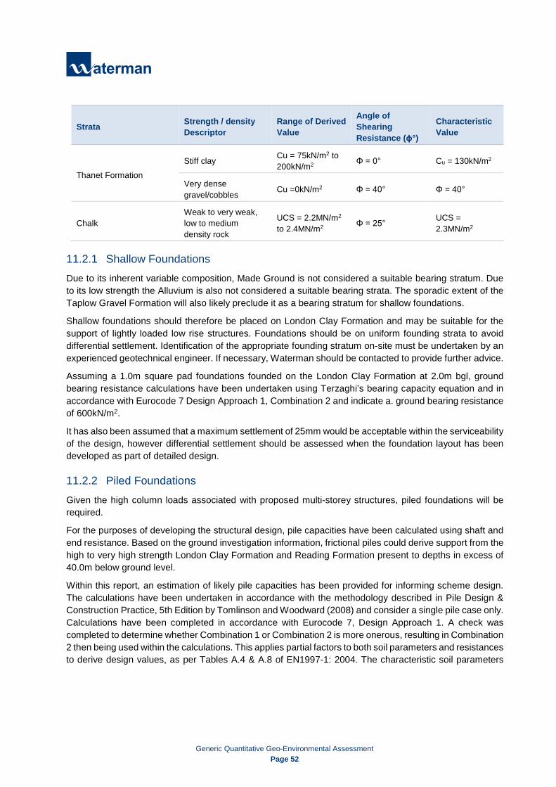
Generic Quantitative Geo-Environmental Assessment
Page 52
Strata Strength / density Descriptor
Range of Derived Value
Angle of Shearing Resistance (ɸ°)
Characteristic Value
Thanet Formation Stiff clay Cu = 75kN/m2 to
200kN/m2 Φ = 0° Cu = 130kN/m2
Very dense gravel/cobbles Cu =0kN/m2 Φ = 40° Φ = 40°
Chalk Weak to very weak, low to medium density rock
UCS = 2.2MN/m2 to 2.4MN/m2 Φ = 25° UCS =
2.3MN/m2
11.2.1 Shallow Foundations Due to its inherent variable composition, Made Ground is not considered a suitable bearing stratum. Due to its low strength the Alluvium is also not considered a suitable bearing strata. The sporadic extent of the Taplow Gravel Formation will also likely preclude it as a bearing stratum for shallow foundations.
Shallow foundations should therefore be placed on London Clay Formation and may be suitable for the support of lightly loaded low rise structures. Foundations should be on uniform founding strata to avoid differential settlement. Identification of the appropriate founding stratum on-site must be undertaken by an experienced geotechnical engineer. If necessary, Waterman should be contacted to provide further advice.
Assuming a 1.0m square pad foundations founded on the London Clay Formation at 2.0m bgl, ground bearing resistance calculations have been undertaken using Terzaghi’s bearing capacity equation and in accordance with Eurocode 7 Design Approach 1, Combination 2 and indicate a. ground bearing resistance of 600kN/m2.
It has also been assumed that a maximum settlement of 25mm would be acceptable within the serviceability of the design, however differential settlement should be assessed when the foundation layout has been developed as part of detailed design.
11.2.2 Piled Foundations Given the high column loads associated with proposed multi-storey structures, piled foundations will be required.
For the purposes of developing the structural design, pile capacities have been calculated using shaft and end resistance. Based on the ground investigation information, frictional piles could derive support from the high to very high strength London Clay Formation and Reading Formation present to depths in excess of 40.0m below ground level.
Within this report, an estimation of likely pile capacities has been provided for informing scheme design. The calculations have been undertaken in accordance with the methodology described in Pile Design & Construction Practice, 5th Edition by Tomlinson and Woodward (2008) and consider a single pile case only. Calculations have been completed in accordance with Eurocode 7, Design Approach 1. A check was completed to determine whether Combination 1 or Combination 2 is more onerous, resulting in Combination 2 then being used within the calculations. This applies partial factors to both soil parameters and resistances to derive design values, as per Tables A.4 & A.8 of EN1997-1: 2004. The characteristic soil parameters
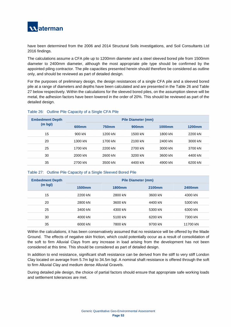
Generic Quantitative Geo-Environmental Assessment
Page 53
have been determined from the 2006 and 2014 Structural Soils investigations, and Soil Consultants Ltd 2016 findings.
The calculations assume a CFA pile up to 1200mm diameter and a steel sleeved bored pile from 1500mm diameter to 2400mm diameter, although the most appropriate pile type should be confirmed by the appointed piling contractor. The pile capacities presented herein should therefore be considered as outline only, and should be reviewed as part of detailed design.
For the purposes of preliminary design, the design resistances of a single CFA pile and a sleeved bored pile at a range of diameters and depths have been calculated and are presented in the Table 26 and Table 27 below respectively. Within the calculations for the sleeved bored piles, on the assumption sleeve will be metal, the adhesion factors have been lowered in the order of 20%. This should be reviewed as part of the detailed design.
Table 26: Outline Pile Capacity of a Single CFA Pile
Embedment Depth (m bgl)
Pile Diameter (mm)
600mm 750mm 900mm 1000mm 1200mm
15 900 kN 1200 kN 1500 kN 1800 kN 2200 kN
20 1300 kN 1700 kN 2100 kN 2400 kN 3000 kN
25 1700 kN 2200 kN 2700 kN 3000 kN 3700 kN
30 2000 kN 2600 kN 3200 kN 3600 kN 4400 kN
35 2700 kN 3500 kN 4400 kN 4900 kN 6200 kN
Table 27: Outline Pile Capacity of a Single Sleeved Bored Pile
Embedment Depth (m bgl)
Pile Diameter (mm)
1500mm 1800mm 2100mm 2400mm
15 2200 kN 2800 kN 3600 kN 4300 kN
20 2800 kN 3600 kN 4400 kN 5300 kN
25 3400 kN 4300 kN 5300 kN 6300 kN
30 4000 kN 5100 kN 6200 kN 7300 kN
35 6000 kN 7800 kN 9700 kN 11700 kN
Within the calculations, it has been conservatively assumed that no resistance will be offered by the Made Ground. The effects of negative skin friction, which could potentially occur as a result of consolidation of the soft to firm Alluvial Clays from any increase in load arising from the development has not been considered at this time. This should be considered as part of detailed design.
In addition to end resistance, significant shaft resistance can be derived from the stiff to very stiff London Clay located on average from 5.7m bgl to 34.5m bgl. A nominal shaft resistance is offered through the soft to firm Alluvial Clay and medium dense Alluvial Gravels.
During detailed pile design, the choice of partial factors should ensure that appropriate safe working loads and settlement tolerances are met.

Generic Quantitative Geo-Environmental Assessment
Page 54
Subject to any piling trials, an acceptable percentage of piles should be load tested to at least twice the working load. All piles should be integrity tested.
The depths tabulated above are embedment depth into London Clay Formation (up to 30m bgl) and Reading Formation (up to 35m bgl). Where pile groups are installed, the efficiency of each pile group should also be assessed and the serviceability of each pile / pile group should be checked as part of detailed design. It may therefore be necessary to increase the embedment depths and/or diameters tabulated above to confirm reliability and serviceability of piles and pile groups. The final design of the piles will be the responsibility of the piling contractor. An allowance for probing of pile positions and/or drilling of obstructions should be allocated. The carrying capacity of the actual pile groups will in part depend on the number, type and size of pile chosen by the contractor and the quality of workmanship. Subject to any piling trials, an acceptable percentage of piles should be load tested to at least twice working load.
All piles should be integrity tested. Significant underground obstructions were encountered by the ground investigations, such as buried concrete obstructions. The pile design should allow for the presence of any such obstructions. On significantly contaminated land, the Environment Agency may object to the use of piles on the basis that they can introduce pathways for contaminant migration. Such objections can usually be overcome if piles are designed in accordance with the EA advice "Piling and Penetrative Ground Improvement Methods on Land Affected by contamination: Guidance on Pollution Prevention”. (NC/99/73, 2001). Consideration should be given to the re-use of pile arisings if piles are used. It may be possible to re-use pile arisings subject to risk assessment; however, certainty of use and volume should be confirmed in accordance with the requirements of CL:AIRE guidance. Given the proximity of existing structures, the effects of noise and vibration (e.g. from piling plant) should be addressed as part of the contractors method statement.
11.2.3 Floor Slabs Due to the thickness and variability of the Made Ground encountered at surface across the Site, ground-bearing floor slabs are not considered suitable and floor slabs should be of suspended design where the thickness of Made Ground is greater than 600mm. This should be considered in conjunction the wider foundation design strategy, accounting for the likelihood of piled foundations. The design of the slabs should only be finalised on completion of gas monitoring in order to allow for the incorporation of gas protection measures (if any).
11.2.4 Basements The redevelopment of Brent Cross includes the construction of two basements with a finished floor level of +35.365m OD within the London Clay stratum. It is most likely that the groundwater encountered beneath the Site is mobile within the Made Ground, Alluvium and Taplow Gravel Formation, over the relatively impermeable London Clay Formation stratum. Therefore, it is possible that the new basements may create a ‘cut off’ obstruction to groundwater flow beneath the Site. The new basements are therefore expected to have an effect on the hydrological flows below this site and the adjacent properties.
As per BS:8102 (2009), groundwater levels at the basements are considered ‘High’ and therefore watertightness is of concern. It is understood that the basements will be formed by means of a retaining wall, formed of a secant piled wall.

Generic Quantitative Geo-Environmental Assessment
Page 55
Given the high groundwater level, the effect of uplift on the basement slab should be considered as part of detailed design although acknowledging that the proposed development comprises multi-storey buildings any effect is considered likely to be ‘insignificant’.
11.2.5 Shrinkability / Volume Change Potential Foundations placed on shrinkable soils should be deepened where necessary to accommodate the effects of trees and hedgerows. Where foundations are beyond the influence of existing and proposed planting (i.e. 1.5 times the mature tree height), the minimum founding depth of a high volume change potential in the London Clay Formation would be 1.0m below existing or proposed ground level.
Foundations within the zone of influence of existing or proposed trees should be deepened as necessary in accordance with recommendations provided in NHBC Chapter 4 – Building Near Trees (NHBC Standards, 2011). If trees are present within influencing distance of proposed foundations, a tree survey should be undertaken to identify appropriate founding depths.
The London Clay Formation has been shown to have a high shrinkability. The presence of the clay mineral smectite renders the London Clay Formation particularly susceptible to heave caused by alternate wetting and drying near the surface. Although the London Clay has been recorded at a minimum depth of 0.20m bgl (WS676), the effect of any volume change minor influence may be considered minor, however this should be considered during the detailed design.
11.2.6 Design Class for Concrete Based on the characteristic values derived from BRE SD1 testing, the Design Sulphate (DS) and Aggressive Chemical Environment for Concrete (ACEC) classifications, assuming mobile groundwater, are considered to be:
• Concrete in contact with Made Ground: DS-3 AC-3
• Concrete in contact with Alluvium: DS-3 AC-4
• Concrete in contact with Taplow Gravel Formation: DS-1 AC-1
• Concrete in contact with London Clay Formation: DS-4 AC-4
• Concrete in contact with Reading Formation: DS-1 AC-1
11.2.7 Groundwater / Stability of Excavations The redevelopment operations will include shallow and deep excavations associated with service runs, foundation and basement excavations. It is understood that the basement excavation will be by means of forming secant piled walls which will provide retention as well as groundwater control.
Based on observations made during fieldwork, shallow excavations (<1.2m) are likely to be stable in the short term. During the ground investigation the groundwater levels were observed at a minimum depth below existing ground level of 0.10mbgl (+41.80m OD) in BH433 in Made Ground. It is possible that perched water may be present, and that groundwater levels are likely to fluctuate dependent on the time of year and prevailing weather conditions, it is considered the next minimum depth of groundwater encountered 0.5m bgl (BH472) be assumed as the groundwater level. Groundwater inflow to excavations may promote instability and temporary works measures should include an allowance for groundwater control. In addition,

Generic Quantitative Geo-Environmental Assessment
Page 56
pockets of perched groundwater and unstable materials in other areas of the Site which have not been investigated cannot be entirely discounted.
In line with BS:6031 (2009), all excavations should be examined daily by a competent person to ensure that they remain safe. Where the sides cannot be graded back to a safe angle, as approved by a competent and experienced person, their continued stability should not be taken for granted. All excavations of greater than 1.2m depth requiring man entry must be provided with a suitably designed shoring support system. For excavations of over 0.5m depth, groundwater control in the form of excavation of sumps and pumping to agreed discharge points may be required.
For the construction of the ground floor slabs with finished floor level of +42.365m OD and basement structures with finished floor level of +35.365m OD; and in accordance with BS:8102 (2009) the groundwater is considered ‘Variable’ and ‘High’ respectively.
The presence of water-bearing strata within or immediately below the excavation requires dewatering both to allow excavation in the dry and to control pore pressures to prevent base heave. Some of these measures are exclusion techniques which include: permeation grouting, ground freezing, and compressed air and, the provision of a cut-off or cofferdam. Appropriate dewatering measures employed should be in accordance with relevant guidance such as CIRIA Report C750, Groundwater control: design and practice, second edition (2016).
11.2.8 Pavement Design The in-situ CBR testing on the Made Ground has produced a value range of 2% to >33%. Assuming the lowest two CBR results are associated with soft spots related to cohesive pockets, it could reasonably be assumed that granular Made Ground will provide a minimum CBR 15%. However, the extent of soft spots is unproven and hence CBR values are likely to be highly variable over the footprint of the scheme.
11.2.9 Material Reusability Excavations will take place to create the piles as well as the basements, generating volumes of Made Ground, Alluvium, Taplow Gravel Formation and London Clay Formation. Consideration should be given to the re-use of arisings from foundation trenches/ piles / basements / drainage runs etc. Where contamination has been encountered, it may be possible to re-use excavation arisings subject to risk assessment; however, certainty of use and volume should be confirmed in accordance with the requirements of CL:AIRE guidance.
As per Manual of Contract Documents for Highway Works Volume 1, Specification for Highway Works (SHW), Series 600, particle size distribution tests have indicated that the granular Made Ground deposits are likely to fall within the grading envelope of a Class 2C stoney cohesive general fill material.
Material grading testing indicates that the Alluvial material would broadly fit within the grading envelope of SHW Class 2C stoney cohesive fill. However, shear strength and Atterberg limits testing indicates that the material would likely suitable for use as a bulk or landscape fill only and not suitable for the direct support of structural loads.
Whilst the particle size distribution tests have indicated that the London Clay Formation and Reading Formation are likely to fall within the grading envelope of a SHW Class 2A/2B cohesive fill and as such, this material may be used as a general fill, although acceptability testing will be required as per Manual of Contract Documents for Highway Works, Volume 1, Specification for Highway Works, Series 600. If these

Generic Quantitative Geo-Environmental Assessment
Page 57
materials meet requirements, they may be suitable for use as a general fill. However, they will not be suitable for direct support of structural loads.

Generic Quantitative Geo-Environmental Assessment
Page 58
12. Preliminary Waste Classification Assessment The process of waste classification is set out in Appendix I.
12.1 Introduction PWCA has been undertaken on discreet soil samples recovered from boreholes and window sample holes undertaken as part of the Structural Soils 2006 and 2014 ground investigations, and the Soil Consultants 2016 ground investigation at the Site. The samples selected for analysis were recovered from the proposed basement area in the centre of the Site, and area of proposed levelling in the east. The samples collected from each location are discreet and have not been sampled in strict accordance with UK Environment Agencies Waste Classification – Guidance on the classification and assessment of waste (1st edition 2015) Technical Guidance WM3. The assessment should be regarded as indicative only. Further assessment will be required once it is known how the waste will arise, and what off-site recovery or disposal options are available.
The assessment considers whether or not the waste displays hazardous properties, and the findings of additional waste acceptance criteria (WAC) testing to indicate likely classification of soils for off-Site landfill disposal.
The hazardous property assessment has been undertaken using HazWasteOnlineTM, a web-based tool for classifying hazardous waste. The tool follows the latest Environment Agencies guidance and European regulations. A summary of the assessment results is provided in Section 12.2.
12.2 Hazardous Property Assessment The dry soils chemical analysis results from the Site Investigations have been entered into HazWasteOnlineTM. A total of 24no. samples of Made Ground and 3no. samples of Alluvium collected as part of the Soil Consultants investigation, and 36no. samples of Made Ground collected from the Aecom investigation have been screened for hazardous properties.
Results from the HazWasteOnlineTM assessment are included in Appendix I.
Of the 60no. Made Ground dry soils samples screened, 8no. have returned hazardous properties by HazWasteOnlineTM. The 3no. Alluvium samples did not return any hazardous properties.
Details of the Made Ground samples identified as containing hazardous properties are provided in Table 28.
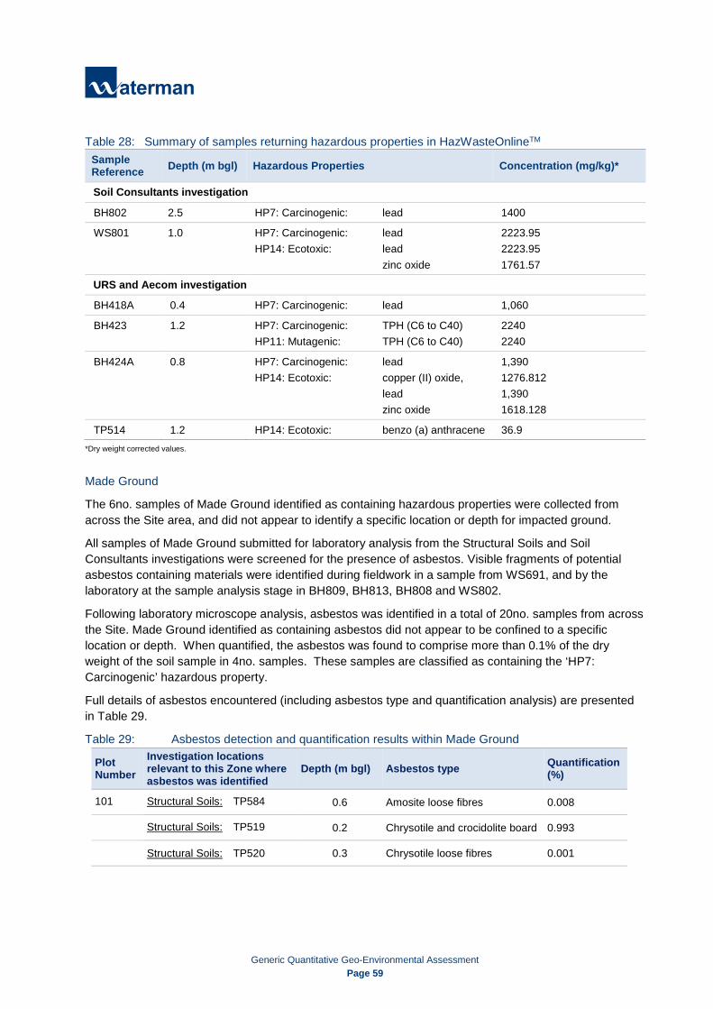
Generic Quantitative Geo-Environmental Assessment
Page 59
Table 28: Summary of samples returning hazardous properties in HazWasteOnlineTM
*Dry weight corrected values.
Made Ground
The 6no. samples of Made Ground identified as containing hazardous properties were collected from across the Site area, and did not appear to identify a specific location or depth for impacted ground.
All samples of Made Ground submitted for laboratory analysis from the Structural Soils and Soil Consultants investigations were screened for the presence of asbestos. Visible fragments of potential asbestos containing materials were identified during fieldwork in a sample from WS691, and by the laboratory at the sample analysis stage in BH809, BH813, BH808 and WS802.
Following laboratory microscope analysis, asbestos was identified in a total of 20no. samples from across the Site. Made Ground identified as containing asbestos did not appear to be confined to a specific location or depth. When quantified, the asbestos was found to comprise more than 0.1% of the dry weight of the soil sample in 4no. samples. These samples are classified as containing the ‘HP7: Carcinogenic’ hazardous property.
Full details of asbestos encountered (including asbestos type and quantification analysis) are presented in Table 29.
Table 29: Asbestos detection and quantification results within Made Ground
Plot Number
Investigation locations relevant to this Zone where asbestos was identified
Depth (m bgl) Asbestos type Quantification (%)
101 Structural Soils: TP584 0.6 Amosite loose fibres 0.008
Structural Soils: TP519 0.2 Chrysotile and crocidolite board 0.993
Structural Soils: TP520 0.3 Chrysotile loose fibres 0.001
Sample Reference Depth (m bgl) Hazardous Properties Concentration (mg/kg)*
Soil Consultants investigation
BH802 2.5 HP7: Carcinogenic: lead 1400
WS801 1.0 HP7: Carcinogenic: lead HP14: Ecotoxic: lead zinc oxide
2223.95 2223.95 1761.57
URS and Aecom investigation
BH418A 0.4 HP7: Carcinogenic: lead 1,060
BH423 1.2 HP7: Carcinogenic: TPH (C6 to C40) HP11: Mutagenic: TPH (C6 to C40)
2240 2240
BH424A 0.8 HP7: Carcinogenic: lead HP14: Ecotoxic: copper (II) oxide, lead zinc oxide
1,390 1276.812 1,390 1618.128
TP514 1.2 HP14: Ecotoxic: benzo (a) anthracene 36.9

Generic Quantitative Geo-Environmental Assessment
Page 60
Plot Number
Investigation locations relevant to this Zone where asbestos was identified
Depth (m bgl) Asbestos type Quantification (%)
102 Soil Consultants: BH809 0.5 Amosite free fibres Chrysotile free fibres^ <0.001
104 Structural Soils: WS601 1.0 Chrysotile loose fibres 0.011
105 Structural Soils: WS690 1.0 Amosite loose fibres <0.001
Structural Soils: WS691 0.9 Amosite loose fibres
Amosite, crocidolite and chrysotile cement tile*
0.003 Solid fragment
Structural Soils: BH412 0.8 Amosite cement and loose fibres 0.05
Soil Consultants: BH813 2.2 Chrysotile lagging^ 0.115
Soil Consultants: BH815 0.5 Amosite free fibres <0.001
108 Soil Consultants: BH808 3.0 Amosite and chrysotile cement^ and lagging^ 0.082
109 Structural Soils: WS679 1.1 Amosite loose insulation 0.003
110 Structural Soils: WS677A 1.2 Chrysotile loose fibres Amosite loose fibres <0.001
K20 Structural Soils: BH461 1.0 Chrysotile loose insulation 0.261
K31 Soil Consultants: WS802 2.5 Chrysotile and crocidolite free fibres^ and sprayed coating 0.021
K38
Structural Soils: TP512 1.1 Chrysotile cement 0.018
Structural Soils: TP514 1.2 Chrysotile cement 0.024
Structural Soils: BH421 1.0 Chrysotile board 0.001
*Asbestos visible to the naked eye in the field.
^asbestos not visible in the field but visible in laboratory analysis.
Alluvium
No hazardous properties were reported in the Alluvium samples analysed.
12.3 Waste Acceptance Criteria In addition to the HazWasteOnlineTM assessment, WAC analysis was undertaken on 4no. samples of Made Ground and a single sample of Alluvium to indicate suitability for disposal to a non-hazardous landfill as inert waste or a hazardous waste landfill without further treatment.

Generic Quantitative Geo-Environmental Assessment
Page 61
Table 30: Summary of WAC Results
Sample Reference Strata
Hazard Property Assessment
Comment
BH804 2.5m bgl
Made Ground
Non-hazardous
Failed the inert WAC for sulphate. However, the value total dissolved solids can be used instead of sulphate (EU Council decision annex 2003/33/EC, 2002). The sample does not fail the total dissolved solids criteria and therefore passes the inert WAC.
BH809 0.5m bgl
Made Ground
Non-hazardous
Did not exceed inert waste chemical criteria, however visible chrysotile and amosite asbestos were identified by the laboratory in the sample. Therefore, these soils would be unacceptable to landfills as inert waste and would likely be classified as hazardous mixed waste.
BH813 2.2m bgl
Made Ground
Non-hazardous
Did not exceed hazardous waste chemical criteria, however visible chrysotile asbestos was identified by the laboratory in the sample. Therefore, these soils would be unacceptable to landfills as inert waste and would likely be classified as hazardous mixed waste
WS804 0.5m bgl
Made Ground
Non-hazardous Failed the inert waste criteria for total dissolved solids and sulphate.
BH810 2.5m bgl
Alluvium Non-hazardous Failed the inert waste criteria for fluoride.
Material to be removed for basement excavation
Made Ground at BH809 at 0.5m bgl, within the area to be excavated for the basement construction was reported as containing no hazardous properties and passing the inert WAC. However, visible asbestos was identified in Made Ground at this location. Therefore, it is considered unlikely these soils would be acceptable at an inert landfill. Where the soil matrix has been reported as containing no hazardous properties but visible asbestos has been identified this soil would likely be classified as a mixed waste.
Soils containing no hazardous properties and asbestos fibres at concentrations below the hazardous waste threshold would unlikely to be acceptable at an inert waste landfill. The presence of asbestos fibres in soils can be indicative of weathered asbestos fragments.
The single sample of Alluvium collected from within the basement area (BH810 – 2.5m bgl) exceeded the inert WAC for fluoride. However, this may be an anomaly and not representative of the Alluvium present across the Site. Natural uncontaminated soils may be acceptable as inert waste without testing at some landfills and may be used suitable for use directly at sites operating in accordance with the CL:AIRE Definition of Waste: Development Industry Code of Practice (DoWCoP);

Generic Quantitative Geo-Environmental Assessment
Page 62
Material to be removed for Site levelling
The assessment indicates that Made Ground around BH804 in the south-central area of the Site may be suitable for disposal to an inert waste landfill, contingent on no asbestos being identified in the arisings. Made Ground around WS804 in the centre-west of the Site may be suitable for disposal as non-hazardous waste, assuming visible asbestos is not present in arisings.
The assessment has also indicated Made Ground around BH813 in the east of the Site does not contain hazardous properties. However, due to the visible asbestos identified, it may require disposal as mixed waste.
Soils containing no hazardous properties and asbestos fibres at concentrations below the hazardous waste threshold would unlikely to be acceptable at an inert landfill. The presence of asbestos fibres in soils can be indicative of weathered asbestos fragments.
Natural uncontaminated soils from, the Taplow Gravel Formation, the London Clay Formation and Lambeth Group may be acceptable as inert waste without testing at some landfills and may be used suitable for use directly at sites operating in accordance with the DoWCoP.
12.4 Preliminary Waste Classification Assessment Summary The Preliminary Waste Classification Assessment has indicated that the relevant EWC codes for the disposal of the soils, as shown in Table 30.
Table 31: Summary of Likely Waste Streams
Material Likely EWC Code
EWC Code Description
Typical Description of Material
Relevant Investigation
Locations
Made Ground containing no hazardous properties 17 05 04
Soils and stones other than those mentioned in 17 05 03.
Gravelly clay with flint, brick, concrete, wood, clinker, glass with occasional pockets of ash, silt and sand.
BH804
Made Ground containing hazardous properties 17 05 03*
Soils and stones containing hazardous substances.
WS804, BH802, WS801, BH418A, BH423, BH424A, TP514, TP519, WS691, BH813, BH461
Made Ground containing no hazardous properties but contains visible fragments of asbestos containing material
17 05 04 and
17 06 05*
Soils and stones other than those mentioned in 17 05 03 and Construction material containing asbestos.
BH809, BH813
Alluvium 17 05 04
Soils and stones other than those mentioned in 17 05 03.
Silty, slightly sandy, gravelly clay with occasional sand partings, occasional rootlets, rare black staining and peat are noted.
BH810
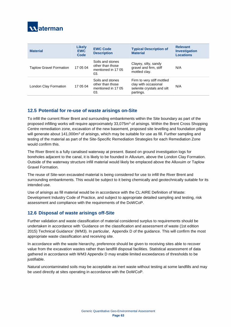
Generic Quantitative Geo-Environmental Assessment
Page 63
12.5 Potential for re-use of waste arisings on-Site To infill the current River Brent and surrounding embankments within the Site boundary as part of the proposed infilling works will require approximately 33,075m3 of arisings. Within the Brent Cross Shopping Centre remediation zone, excavation of the new basement, proposed site levelling and foundation piling will generate about 141,000m3 of arisings, which may be suitable for use as fill. Further sampling and testing of the material as part of the Site-Specific Remediation Strategies for each Remediation Zone would confirm this.
The River Brent is a fully canalised waterway at present. Based on ground investigation logs for boreholes adjacent to the canal, it is likely to be founded in Alluvium, above the London Clay Formation. Outside of the waterway structure infill material would likely be emplaced above the Alluvuim or Taplow Gravel Formation.
The reuse of Site-won excavated material is being considered for use to infill the River Brent and surrounding embankments. This would be subject to it being chemically and geotechnically suitable for its intended use.
Use of arisings as fill material would be in accordance with the CL:AIRE Definition of Waste: Development Industry Code of Practice, and subject to appropriate detailed sampling and testing, risk assessment and compliance with the requirements of the DoWCoP.
12.6 Disposal of waste arisings off-Site Further validation and waste classification of material considered surplus to requirements should be undertaken in accordance with ‘Guidance on the classification and assessment of waste (1st edition 2015) Technical Guidance’ (WM3). In particular, Appendix D of the guidance. This will confirm the most appropriate waste classification and receiving site.
In accordance with the waste hierarchy, preference should be given to receiving sites able to recover value from the excavation wastes rather than landfill disposal facilities. Statistical assessment of data gathered in accordance with WM3 Appendix D may enable limited exceedances of thresholds to be justifiable.
Natural uncontaminated soils may be acceptable as inert waste without testing at some landfills and may be used directly at sites operating in accordance with the DoWCoP.
Material Likely EWC Code
EWC Code Description
Typical Description of Material
Relevant Investigation Locations
Taplow Gravel Formation 17 05 04
Soils and stones other than those mentioned in 17 05 03.
Clayey, silty, sandy gravel and firm, stiff mottled clay.
N/A
London Clay Formation 17 05 04
Soils and stones other than those mentioned in 17 05 03.
Firm to very stiff mottled clay with occasional selenite crystals and silt partings.
N/A

Generic Quantitative Geo-Environmental Assessment
Page 64
Acceptance of waste is at the discretion of the receiving site. It is recommended that the receiving site operator is consulted at the appropriate time to discuss the conditions of its Environmental Permit.
Segregation of different waste streams would be required prior to disposal of materials off-Site. For example, soils displaying hazardous properties segregated from those displaying no hazardous properties. Also, soils identified as containing asbestos should be segregated from those identified as not containing asbestos.

Generic Quantitative Geo-Environmental Assessment
Page 65
13. Conclusions
13.1 Environmental Conclusions and Recommendations Following the implementation of the ground investigation, the pollutant linkages identified have been re-evaluated and reclassified in relation to the additional information obtained. The results of the reassessment are summarised in Table 32:
Table 32: Estimation of environmental risks associated with the Site
Receptor Potential sources Pathways Risk Justification Residual Risk
Future Site users / visitors
Contamination and asbestos in Made Ground, shallow soils and shallow groundwater from on-Site and adjacent off-Site land uses.
Dermal contact with contaminated soils in areas of soft landscaping. Low
Historically the Site and surrounding area has been occupied by various works and industrial land uses which may have led to localised ground contamination. The Structural Soils and Soil Consultants ground investigations at the Site identified hotspots of metals and PAH within shallow soils at the Site, along with minor metals and PAH contamination within shallow groundwater. Asbestos was also detected in samples across the total Site area. The proposed development involves hardstanding and buildings covering the majority of the Site area. This, alongside the use of an appropriate thickness of certified clean, uncontaminated topsoil will prevent future Site users contacting ground contamination in soft landscaped areas.
Low
Ground gas arising from Made Ground and Alluvium, and vapours from hydrocarbon contamination in shallow groundwater.
Accumulation in confined spaces, leading to inhalation followed by asphyxiation and risk of explosion.
Medium
The nine rounds of ground gas monitoring by Structural Soils and six rounds of ground gas monitoring by Soil Consultants found the overall ground gas regime at the Site was Characteristic Situation 1 (very low risk). However, a consistently elevated methane reading was detected in a single well in the south of the Site. When these readings were considered as a worst-case scenario for the overall Site, the Characteristic Situation raised to CS2 (low risk). This monitoring well is within a section of the Site where basement excavation is planned. This will remove all Made Ground and Alluvium from the area, likely removing the source material for the elevated gas readings. However, gas protection measures should still be considered in buildings in this area of the Site, in order to fully reduce the risk to future Site users to low.
Low

Generic Quantitative Geo-Environmental Assessment
Page 66
Receptor Potential sources Pathways Risk Justification Residual Risk
Soil and groundwater samples did not indicate extensive hydrocarbon contamination, although some elevated naphthalene levels were observed. Vapour monitoring by Soil Consultants did not detect significantly elevated readings. The Site is not considered to be at risk of vapours.
Off-Site residents/users
Contamination and asbestos in Made Ground and shallow soils.
Windborne, potentially contaminated construction dust. Runoff from stockpiled soils.
Medium
An Asbestos Management Plan (AMP) will be prepared for the Site, to include plans for managing asbestos both in structures to be demolished or modified, and within the Made Ground. A Construction Environmental Monitoring Plan (CEMP) will be prepared for the works, including measures to minimise runoff from stockpiled soils, manage groundwater in excavations and suppress the generation of dust. Construction materials brought on-Site as part of works should be appropriately stored to prevent spills and leaks. This should prevent potentially contaminated material reaching off-Site residents or users.
Low
Contamination in shallow groundwater.
Lateral migration off-Site via shallow groundwater flow. Low
Historically, the area surrounding the Site has supported similar industrial uses to the Site itself. Shallow groundwater is likely to have been impacted by contamination and therefore will not be further impacted by migration of shallow groundwater from the Site. A significant area of land surrounding the Site is already covered by hardstanding, or proposed to be redeveloped which is likely to prevent future off-Site users contacting shallow groundwater.
Low
Site/Construction workers
Contamination and asbestos in Made Ground, shallow soils, and shallow groundwater. Ground gas and vapours.
Accumulation in confined spaces, leading to inhalation followed by asphyxiation and risk of explosion. Dermal contact and ingestion of contaminated soils and groundwater. Inhalation of dust.
Medium
The CEMP and AMP will include measures to protect construction workers from contact with contaminated materials, including asbestos. Construction workers will be provided with personal protective equipment (PPE) and respiratory protective equipment (RPE) where appropriate. Workers should be aware of good hygiene measures as protection against direct contact with contaminated Made Ground, asbestos, contaminated groundwater, ground gas, vapours and dust inhalation.
Low
Future on-Site structures and services
Contamination in Made Ground, shallow soils, and shallow groundwater.
Direct contact with building foundations and buried services leading to chemical attack.
Medium
Geotechnical investigation has identified the suitable design classes for concrete to be used in buried structures and services at the completed development. Barrier water supply pipes should be used at the development in accordance with UKWIR guidance.
Low

Generic Quantitative Geo-Environmental Assessment
Page 67
Receptor Potential sources Pathways Risk Justification Residual Risk
Ground gas and vapours.
Accumulation in confined spaces, leading to risk of explosion. Medium
Ground gas and vapour monitoring indicates the majority of the Site is CS1 (very low risk) for ground gas, with the area to be excavated for the basement assessed as CS2 (low risk). Basic protection measures commensurate for a CS2 Site may be required at the completed development. Vapour levels are not considered to pose a risk to the completed development.
Low
Plants and vegetation in areas of soft landscaping
Contamination in Made Ground, shallow soils, and shallow groundwater.
Direct contact, uptake from contaminated soils and/or groundwater
Medium
All soft landscaping at the completed development would be situated in an appropriate thickness of imported, certified clean cover material. This would prevent plants at the completed development contacting any ground contamination beneath the Site.
Low
Surface water at the River Brent
Contamination in Made Ground, shallow soils, and shallow groundwater.
Migration of groundwater to the River Brent. Low
The diverted River Brent off-Site will be a canalised structure, hydraulically isolated from shallow groundwater. Therefore, it is unlikely to be impacted by contamination at the completed development.
Low
Spills of construction materials stored on-Site during development works
Spills of construction materials reaching the River Brent via surface run off prior to infilling works completion.
Medium
A CEMP should be prepared for the demolition and construction works on-Site, detailing measures to minimise the potential risk to controlled waters. Construction materials brought on-Site as part of works should be appropriately stored to prevent spills and leaks. This should prevent potentially contaminated material reaching the River Thames.
Low

Generic Quantitative Geo-Environmental Assessment
Page 68
Receptor Potential sources Pathways Risk Justification Residual Risk
Shallow perched groundwater in the Taplow Gravel Formation near the A41/A406 junction
Contamination in Made Ground and shallow soils.
Remobilisation of contamination by rainfall infiltration following removal of hardstanding during construction works.
Remobilisation of contamination via potential soakaways.
Low
The CEMP should include measures to minimise rainwater infiltration to exposed ground, or the potential for construction spills during the demolition and construction works. Rainwater infiltration via soft landscaping and private gardens is possible at the completed development. However, this is likely to be limited as the majority of the Site will be covered by buildings and hardstanding. Contamination in the Made Ground and shallow soils is not extensive across the Site, meaning that there are unlikely to be significant impacts from any mobilisation.
Low
Shallow perched groundwater off-Site
Contamination shallow groundwater.
Lateral migration off-Site via shallow groundwater flow.
Low
Shallow off-Site groundwater is likely to have been impacted by contamination and therefore will not be further impacted by migration of shallow groundwater from the Site. A significant area of land surrounding the Site is already covered by hardstanding, or proposed to be redeveloped which is likely to prevent future off-Site users contacting shallow groundwater.
Low
Deep Secondary A aquifers in the Lambeth Group and Thanet Formation Principal Aquifer in the Chalk Group
Contamination in shallow groundwater. Migration via piled foundations Low
Ground investigation found the Site is underlain by about 28-35m of London Clay Formation, which presents an impermeable barrier for the migration of contaminants to the deep Secondary A and Principal Aquifers. The proposed development is likely to comprise mid-rise buildings, whose foundations may penetrate this layer. A Foundation Works Risk Assessment should be undertaken for the Site. This will inform the most appropriate design for piled foundations, to prevent downward migration of potentially contaminated shallow groundwater from the Made Ground, Alluvium or Taplow Gravel Formation.
Low

Generic Quantitative Geo-Environmental Assessment Page 69
Based on the works undertaken to date and in consideration of the proposed development, the Site’s ground conditions are considered to a have a Low-Medium environmental risk with respect to ground contamination and contaminative liabilities as defined under Part IIA of the Environmental Protection Act 1990.
The following actions are recommended to address the potentially unacceptable risks that remain:
Ground investigation indicates that there is some contamination present in the Made Ground at the Site. A Site-specific Remediation Strategy should be completed for each Remediation Zone detailing how this contamination will be managed, informed by the soil and groundwater results;
The findings of ground gas monitoring indicate the overall Site is Characteristic Situation 1 (very lowrisk). However, consistently elevated methane levels have been found in the south of the Site, whichraise the Characteristic Situation to CS2 (low risk). Although these readings were in an area to beexcavated for the basement, gas protection measures should still be considered in buildings in thisarea of the Site. The vapour risk at the development is assessed as low. The Site-SpecificRemediation Strategy for each Remediation Zone will detail how this will be managed;
A Foundation Works Risk Assessment should be completed for the proposed development, to ensurepiled foundations do not create a pathway for groundwater flow from shallow aquifer above theLondon Clay Formation to deeper aquifers. Piled foundations should be designed in accordance withthe findings of this assessment;
All works at the Site should be undertaken in accordance with the Control of Asbestos Regulations2012. An Asbestos Management Plan (AMP) should be prepared for the Site, to include plans formanaging asbestos both in structures to be demolished or modified, and Made Ground contaminatedwith asbestos;
A Construction Environmental Monitoring Plan (CEMP) should be prepared for the works, includingmeasures to minimise runoff from stockpiled soils, manage groundwater in excavations and suppressthe generation of dust;
During construction works, potentially contaminative substances should be stored and handled inaccordance with the COSHH (Control of Substances hazardous to Health) regulations 2002, to preventcontaminants reaching the ground or the River Brent;
Construction workers should be provided with personal protective equipment (PPE) and respiratoryprotective equipment (RPE) where appropriate. Workers should be aware of good hygiene measuresas protection against direct contact with contaminated Made Ground, asbestos contaminated soils,contaminated groundwater, ground gas, vapours and dust inhalation;
Where Made Ground arisings are proposed to be reused on-Site to infill the River Brent andsurrounding embankments, this material should be demonstrated suitable for use from chemical andgeotechnical perspective. Re-use of soils should be in accordance with the CL:AIRE Definition ofWaste: Development Industry Code of Practice;
A significant amount of crushed aggregate will be generated as a result of demolition of currentbuildings and removal of concrete hardstanding. The production of aggregates should be controlledby the Wrap Quality Protocol for Aggregates;
Dewatering is likely to be necessary during excavation of the basement. Allowance should be madefor the management of impacted groundwater during the Site works;

Generic Quantitative Geo-Environmental Assessment
Page 70
Soft landscaping areas at the development should be planted using an appropriate thickness of imported, certified clean cover material; and
Barrier water supply pipes should be used at the development in accordance with UKWIR guidance.
13.2 Geotechnical Conclusions and Recommendations The proposed Phase 1BN development includes an expansion of the current Brent Cross shopping centre building southwards for mixed retail and commercial uses. The extension will be to a maximum of 5 storeys in height. A single-level basement is proposed, located in the south of the Site. Works will also involve construction of multi-storey car parks above the existing surface level car parks to the west, east and south of the current building. These multi-storey car parks will be entirely above-ground and will extend up to a maximum of 9 levels. It is understood that piled foundations are to be adopted for the proposed Brent Cross development, which will include multi-storey structures with column loads of up to approximately 20,000kN.
For the purposes of developing the structural design, pile capacities have been calculated using shaft and end resistance. Based on the ground investigation information, frictional piles could derive support from the high to very high strength London Clay Formation and Reading Formation present from 0.20m – 7.80m to depths in excess of 40.0m below ground level.
For the purposes of preliminary design, the design resistances of a single CFA pile and a sleeved bored pile at a range of diameters and depths have been calculated and are presented in Section 11, Table 22 and Table 23 respectively.
Based on the characteristic values derived from BRE SD1 testing, the Design Sulphate (DS) and Aggressive Chemical Environment for Concrete (ACEC) classifications, assuming mobile groundwater, are considered to be:
• Concrete in contact with Made Ground: DS-3 AC-3 • Concrete in contact with Alluvium: DS-3 AC-4 • Concrete in contact with Taplow Gravel Formation: DS-1 AC-1 • Concrete in contact with London Clay Formation: DS-4 AC-4 • Concrete in contact with Reading Formation: DS-1 AC-1
Based on observations made during fieldwork, shallow excavations (<1.2m) are likely to be stable in the short term. During the ground investigation the groundwater levels were observed at a minimum depth below existing ground level of 0.10mbgl in the Made Ground. It is possible that perched water may be present, and that groundwater levels are likely to fluctuate dependent on the time of year and prevailing weather conditions, it is considered the next minimum depth of groundwater encountered 0.5m bgl be assumed as the groundwater level. Groundwater inflow to excavations may promote instability and temporary works measures should include an allowance for groundwater control. In addition, pockets of perched groundwater and unstable materials in other areas of the Site which have not been investigated cannot be entirely discounted.
In line with BS:6031 (2009), all excavations should be examined daily by a competent person to ensure that they remain safe. Where the sides cannot be graded back to a safe angle, as approved by a competent and experienced person, their continued stability should not be taken for granted. All excavations of greater than 1.2m depth requiring man entry must be provided with a suitably designed shoring support system. For excavations of over 0.5m depth, groundwater control in the form of excavation of sumps and pumping to agreed discharge points may be required.

Generic Quantitative Geo-Environmental Assessment
Page 71
For the construction of the ground floor slabs and basement structures, and in accordance with BS:8102 (2009) the groundwater is considered ‘Variable’ and ‘High’ respectively.
Excavations will take place to create the piles as well as the basements, generating volumes of Made Ground, Alluvium, Taplow Gravel Formation and London Clay Formation. Consideration should be given to the re-use of arisings from foundation trenches/ piles / basements / drainage runs etc. Where contamination has been encountered, it may be possible to re-use excavation arisings subject to risk assessment; however, certainty of use and volume should be confirmed in accordance with the requirements of CL:AIRE guidance and acceptability testing as per Manual of Contract Documents for Highway Works, Volume 1, Specification for Highway Works, Series 600.

Generic Quantitative Geo-Environmental Assessment Appendices
APPENDICES

Generic Quantitative Geo-Environmental Assessment Appendices
Appendix A Site Plans • Site Location Plan (Fig. A1)
• Site Plan (Fig. A2)
• Ground Investigation Plan (Fig. A3)
• Ground Contamination Exceedances Plan (Fig. A4)
• Proposed Development Plans - Basement and Lower Ground Floor (Fig. A5)
• Conceptual Site Model (Fig. A6)

Project Details
Figure Ref
Date
Figure Title
File Location
Figure 1: Site Location Plan
\\s-lncs\wiel\projects\wic15997\100\graphics\spec\issued figures
WIC15997-100_GR_SPEC_1A
May 2016
WIC15997-100: Brent Cross
www.watermangroup.com
N
Reproduced from the Ordnance Survey maps with the permission of the Controller of Her Majesty’s Stationery Office,© Crown copyright, Waterman Infrastructure & Environment, Pickfords Wharf, Clink Street, London SE1 9DG. Licence number LAN1000628.
© WATERMAN INFRASTRUCTURE & ENVIRONMENT
SITE LOCATION

Project Details
Figure Ref
Date
Figure Title
File Location
Figure 2: Exploratory Hole Location Plan
\\s-lncs\wiel\projects\wic15997\100\graphics\spec\issued figures
WIC15997-100_GR_SPEC_2E
December 2016
WIC15997-100: Brent Cross
www.watermangroup.com
N
Reproduced from the Ordnance Survey maps with the permission of the Controller of Her Majesty’s Stationery Office,© Crown copyright, Waterman Infrastructure & Environment, Pickfords Wharf, Clink Street, London SE1 9DG. Licence number LAN1000628.
© WATERMAN INFRASTRUCTURE & ENVIRONMENT
BH81561m
BH81315m
BH81136m
BH81015m
ANTICIPATEDGROUNDWATER
FLOW DIRECTION
WS8026.45m
BH80835m
BH809 / Soakage Test 215.45m
BH80435m
BH80315m
CBR1
CBR2
CBR3
CBR4
CBR5
CBR6
CBR7
BH80155.5m
BH80515m
BH80615.45m
BH80715.45m
BH81215m
BH814 / Soakage Test 315m
BH80215m
Approximate Location of Proposed Basement
Boreholes
Window Samples
Note:
1. Do not scale from this drawing.
BRE Soakage Test Locations
CBR Test
WS8043m
WS8056.45m
WS8016.45m
WS8036.45m
WS806 / Soakage Test 16.45m
Historical Investigation Locations