ansul sapphire engineered clean agent …fm200.co.id/documentation/manual-book/ansul sapphire...
TRANSCRIPT
ANSUL
SAPPHIRE ENGINEERED
CLEAN AGENT SYSTEM
DESIGN, INSTALLATION, RECHARGE AND MAINTENANCE MANUAL
ANSUL PART NO. 570590-04
UNDERWRITERS LABORATORIES FILE NO. EX-4510
SEPTEMBER 1, 2010
4-1-05 1-6 1
4-15-05 1-20 1
4-1-05 3-5 1
4-1-05 5-11 1
4-1-05 6-2 1
4-1-05 6-3 1
4-1-05 9-1 1
4-1-05 9-2 1
3-1-07 5-2 2
4-1-10 1-1 2
4-1-10 1-3 1
4-1-10 1-8 2
4-1-10 1-9 2
4-1-10 1-10 1
4-1-10 5-15 New
4-1-10 5-16 New
9-1-10 Table of Contents 3
9-1-10 1-2 3
9-1-10 1-4 2
9-1-10 1-7 1
9-1-10 1-11 2
9-1-10 1-15 3
9-1-10 1-19 1
9-1-10 Section II – MSDS Updated
9-1-10 2-7 New
9-1-10 2-8 New
9-1-10 3-2 3
9-1-10 3-4 2
9-1-10 4-2 2
9-1-10 5-1 2
9-1-10 5-3 2
9-1-10 5-4 2
9-1-10 5-5 2
9-1-10 5-6 1
9-1-10 5-7 2
9-1-10 5-8 2
9-1-10 5-9 1
9-1-10 5-10 1
9-1-10 5-12 2
9-1-10 6-1 2
9-1-10 9-4 1
9-1-10 Section X – Example Updated
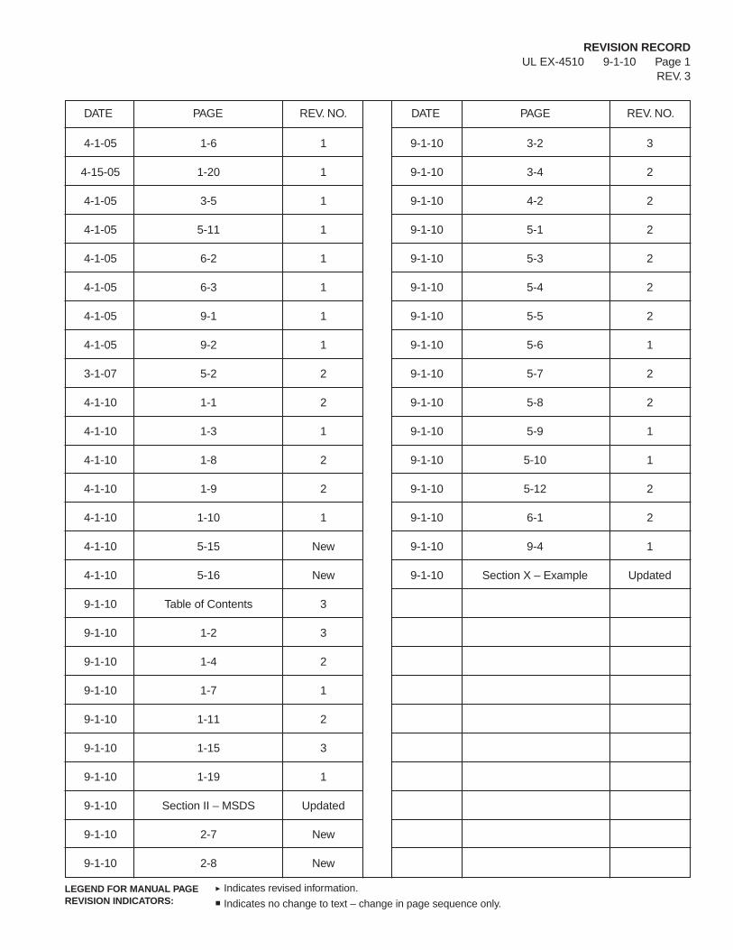
REVISION RECORDUL EX-4510 9-1-10 Page 1
REV. 3
DATE PAGE REV. NO. DATE PAGE REV. NO.
Indicates revised information.
Indicates no change to text – change in page sequence only.LEGEND FOR MANUAL PAGEREVISION INDICATORS:
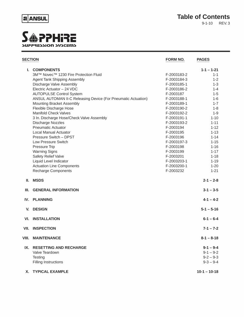
Table of Contents9-1-10 REV. 3
SECTION FORM NO. PAGES________ _________ ______
I. COMPONENTS 1-1 – 1-213M™ Novec™ 1230 Fire Protection Fluid F-2003183-2 1-1Agent Tank Shipping Assembly F-2003184-3 1-2Discharge Valve Assembly F-2003185-1 1-3Electric Actuator – 24 VDC F-2003186-2 1-4AUTOPULSE Control System F-2003187 1-5ANSUL AUTOMAN II-C Releasing Device (For Pneumatic Actuation) F-2003188-1 1-6Mounting Bracket Assembly F-2003189-1 1-7Flexible Discharge Hose F-2003190-2 1-8Manifold Check Valves F-2003192-2 1-93 In. Discharge Hose/Check Valve Assembly F-2003191-1 1-10Discharge Nozzles F-2003193-2 1-11Pneumatic Actuator F-2003194 1-12Local Manual Actuator F-2003195 1-13Pressure Switch – DPST F-2003196 1-14Low Pressure Switch F-2003197-3 1-15Pressure Trip F-2003198 1-16Warning Signs F-2003199 1-17Safety Relief Valve F-2003201 1-18Liquid Level Indicator F-2003203-1 1-19Actuation Line Components F-2003200-1 1-20Recharge Components F-2003232 1-21
II. MSDS 2-1 – 2-8
III. GENERAL INFORMATION 3-1 – 3-5
IV. PLANNING 4-1 – 4-2
V. DESIGN 5-1 – 5-16
VI. INSTALLATION 6-1 – 6-4
VII. INSPECTION 7-1 – 7-2
VIII. MAINTENANCE 8-1 – 8-18
IX. RESETTING AND RECHARGE 9-1 – 9-4Valve Teardown 9-1 – 9-2Testing 9-2 – 9-3Filling Instructions 9-3 – 9-4
X. TYPICAL EXAMPLE 10-1 – 10-18
System ComponentsUL EX-4510 4-1-10 Page 1-1
REV. 2
Novec 1230 fluid has been developed as a halon replace-ment alternative to HFCs, HCFCs, and PFCs in specialhazard, high value applications. It has unique qualities thatprovide the right balance of fire extinguishing performance,end use safety, and environmental sustainability. Novec1230 fluid is low in toxicity and environment impact. It is aliquid at room temperature, with a low vapor pressure,which allows for ease in handling, storage, and shipping.
Novec 1230 fluid is available in two sizes of containers:
Part No. 570650 – 55 gallon (208.2 L) Drum ShippingAssembly
Part No. 570534 – 220 gallon (832.8 L) Tote ShippingAssembly
For complete Material Safety Data Sheet (MSDS) informa-tion, visit ansul.com.
3M™ Novec™ 1230 Fire Protection Fluid
TYCO FIRE SUPPRESSION & BUILDING PRODUCTS, MARINETTE, WI 54143-2542 715-735-7411 Form No. F-2003183-2 Copyright ©2010
ANSUL and SAPPHIRE are trademarks of Tyco Fire Suppression & Building Products or its affiliates.
System ComponentsUL EX-4510 9-1-10 Page 1-2
REV. 3
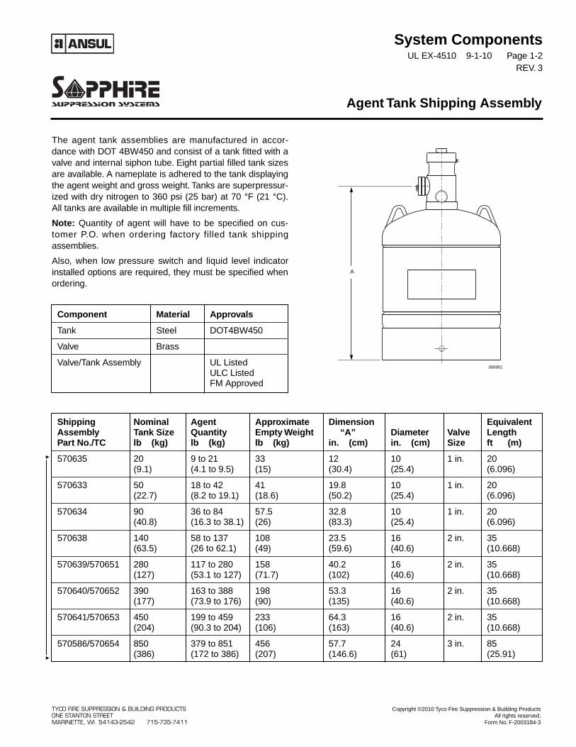
The agent tank assemblies are manufactured in accor-dance with DOT 4BW450 and consist of a tank fitted with avalve and internal siphon tube. Eight partial filled tank sizesare available. A nameplate is adhered to the tank displayingthe agent weight and gross weight. Tanks are superpressur-ized with dry nitrogen to 360 psi (25 bar) at 70 °F (21 °C).All tanks are available in multiple fill increments.
Note: Quantity of agent will have to be specified on cus-tomer P.O. when ordering factory filled tank shippingassemblies.
Also, when low pressure switch and liquid level indicatorinstalled options are required, they must be specified whenordering.
Agent Tank Shipping Assembly
Component Material Approvals
Tank Steel DOT4BW450
Valve Brass
Valve/Tank Assembly UL ListedULC Listed FM Approved
Shipping Nominal Agent Approximate Dimension EquivalentAssembly Tank Size Quantity Empty Weight “A” Diameter Valve LengthPart No./TC lb (kg) lb (kg) lb (kg) in. (cm) in. (cm) Size ft (m)
570635 20 9 to 21 33 12 10 1 in. 20(9.1) (4.1 to 9.5) (15) (30.4) (25.4) (6.096)
570633 50 18 to 42 41 19.8 10 1 in. 20(22.7) (8.2 to 19.1) (18.6) (50.2) (25.4) (6.096)
570634 90 36 to 84 57.5 32.8 10 1 in. 20(40.8) (16.3 to 38.1) (26) (83.3) (25.4) (6.096)
570638 140 58 to 137 108 23.5 16 2 in. 35(63.5) (26 to 62.1) (49) (59.6) (40.6) (10.668)
570639/570651 280 117 to 280 158 40.2 16 2 in. 35(127) (53.1 to 127) (71.7) (102) (40.6) (10.668)
570640/570652 390 163 to 388 198 53.3 16 2 in. 35(177) (73.9 to 176) (90) (135) (40.6) (10.668)
570641/570653 450 199 to 459 233 64.3 16 2 in. 35(204) (90.3 to 204) (106) (163) (40.6) (10.668)
570586/570654 850 379 to 851 456 57.7 24 3 in. 85(386) (172 to 386) (207) (146.6) (61) (25.91)
006901
A
TYCO FIRE SUPPRESSION & BUILDING PRODUCTS Copyright ©2010 Tyco Fire Suppression & Building ProductsONE STANTON STREET All rights reserved.MARINETTE, WI 54143-2542 715-735-7411 Form No. F-2003184-3
System ComponentsUL EX-4510 4-1-10 Page 1-3
REV. 1
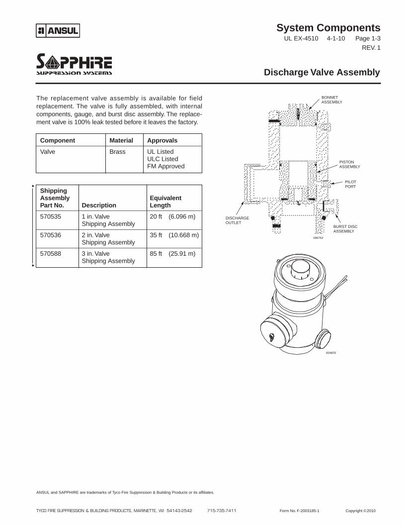
The replacement valve assembly is available for fieldreplacement. The valve is fully assembled, with internalcomponents, gauge, and burst disc assembly. The replace-ment valve is 100% leak tested before it leaves the factory.
Discharge Valve Assembly
TYCO FIRE SUPPRESSION & BUILDING PRODUCTS, MARINETTE, WI 54143-2542 715-735-7411 Form No. F-2003185-1 Copyright ©2010
ANSUL and SAPPHIRE are trademarks of Tyco Fire Suppression & Building Products or its affiliates.
Component Material Approvals
Valve Brass UL ListedULC ListedFM Approved
ShippingAssembly EquivalentPart No. Description Length
570535 1 in. Valve 20 ft (6.096 m)Shipping Assembly
570536 2 in. Valve 35 ft (10.668 m)Shipping Assembly
570588 3 in. Valve 85 ft (25.91 m)Shipping Assembly
004825
006762
BURST DISCASSEMBLY
PISTONASSEMBLY
PILOTPORT
DISCHARGEOUTLET
BONNETASSEMBLY
System ComponentsUL EX-4510 9-1-10 Page 1-4
REV. 2
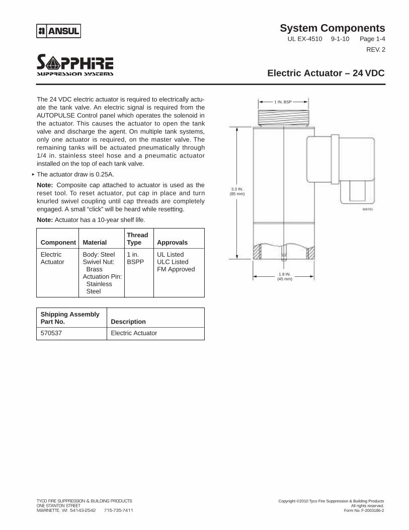
The 24 VDC electric actuator is required to electrically actu-ate the tank valve. An electric signal is required from theAUTOPULSE Control panel which operates the solenoid inthe actuator. This causes the actuator to open the tankvalve and discharge the agent. On multiple tank systems,only one actuator is required, on the master valve. Theremaining tanks will be actuated pneumatically through1/4 in. stainless steel hose and a pneumatic actuatorinstalled on the top of each tank valve.
The actuator draw is 0.25A.
Note: Composite cap attached to actuator is used as thereset tool. To reset actuator, put cap in place and turnknurled swivel coupling until cap threads are completelyengaged. A small “click” will be heard while resetting.
Note: Actuator has a 10-year shelf life.
Electric Actuator – 24 VDC
Shipping AssemblyPart No. Description
570537 Electric Actuator
ThreadComponent Material Type Approvals
Electric Body: Steel 1 in. UL ListedActuator Swivel Nut: BSPP ULC Listed
Brass FM ApprovedActuation Pin:StainlessSteel
006763
1.8 IN.(45 mm)
3.3 IN.(85 mm)
1 IN. BSP
TYCO FIRE SUPPRESSION & BUILDING PRODUCTS Copyright ©2010 Tyco Fire Suppression & Building ProductsONE STANTON STREET All rights reserved.MARINETTE, WI 54143-2542 715-735-7411 Form No. F-2003186-2
System ComponentsUL EX-4510 12-1-03 Page 1-5
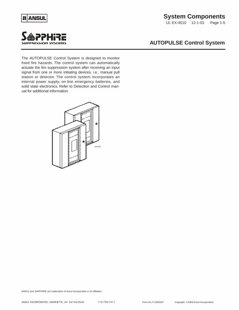
The AUTOPULSE Control System is designed to monitorfixed fire hazards. The control system can automaticallyactuate the fire suppression system after receiving an inputsignal from one or more initiating devices, i.e., manual pullstation or detector. The control system incorporates aninternal power supply, on-line emergency batteries, andsolid state electronics. Refer to Detection and Control man-ual for additional information.
AUTOPULSE Control System
ANSUL INCORPORATED, MARINETTE, WI 54143-2542 715-735-7411 Form No. F-2003187 Copyright ©2008 Ansul Incorporated
ANSUL and SAPPHIRE are trademarks of Ansul Incorporated or its affiliates.
002195
System ComponentsUL EX-4510 4-1-05 Page 1-6
REV. 1
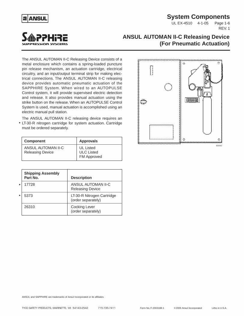
The ANSUL AUTOMAN II-C Releasing Device consists of ametal enclosure which contains a spring-loaded puncturepin release mechanism, an actuation cartridge, electricalcircuitry, and an input/output terminal strip for making elec-trical connections. The ANSUL AUTOMAN II-C releasingdevice provides automatic pneumatic actuation of theSAPPHIRE System. When wired to an AUTOPULSEControl system, it will provide supervised electric detectionand release. It also provides manual actuation using thestrike button on the release. When an AUTOPULSE ControlSystem is used, manual actuation is accomplished using anelectric manual pull station.
The ANSUL AUTOMAN II-C releasing device requires anLT-30-R nitrogen cartridge for system actuation. Cartridgemust be ordered separately.
ANSUL AUTOMAN II-C Releasing Device(For Pneumatic Actuation)
TYCO SAFETY PRODUCTS, MARINETTE, WI 54143-2542 715-735-7411 Form No. F-2003188-1 ©2005 Ansul Incorporated Litho in U.S.A.
ANSUL and SAPPHIRE are trademarks of Ansul Incorporated or its affiliates.
Component Approvals
ANSUL AUTOMAN II-C UL ListedReleasing Device ULC Listed
FM Approved
Shipping AssemblyPart No. Description
17728 ANSUL AUTOMAN II-CReleasing Device
5373 LT-30-R Nitrogen Cartridge(order separately)
26310 Cocking Lever(order separately)
000442
System ComponentsUL EX-4510 9-1-10 Page 1-7
REV. 1
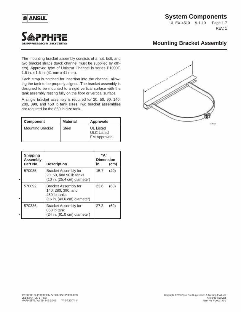
The mounting bracket assembly consists of a nut, bolt, andtwo bracket straps (back channel must be supplied by oth-ers). Approved type of Unistrut Channel is series P1000T,1.6 in. x 1.6 in. (41 mm x 41 mm).
Each strap is notched for insertion into the channel, allow-ing the tank to be properly aligned. The bracket assembly isdesigned to be mounted to a rigid vertical surface with thetank assembly resting fully on the floor or vertical surface.
A single bracket assembly is required for 20, 50, 90, 140,280, 390, and 450 lb tank sizes. Two bracket assembliesare required for the 850 lb size tank.
Mounting Bracket Assembly
Component Material Approvals
Mounting Bracket Steel UL ListedULC ListedFM Approved
Shipping “A”Assembly DimensionPart No. Description in. (cm)
570085 Bracket Assembly for 15.7 (40)20, 50, and 90 lb tanks(10 in. (25.4 cm) diameter)
570092 Bracket Assembly for 23.6 (60)140, 280, 390, and450 lb tanks(16 in. (40.6 cm) diameter)
570336 Bracket Assembly for 27.3 (69)850 lb tank(24 in. (61.0 cm) diameter)
006759
A
TYCO FIRE SUPPRESSION & BUILDING PRODUCTS Copyright ©2010 Tyco Fire Suppression & Building ProductsONE STANTON STREET All rights reserved.MARINETTE, WI 54143-2542 715-735-7411 Form No. F-2003189-1
System ComponentsUL EX-4510 4-1-10 Page 1-8
REV. 2
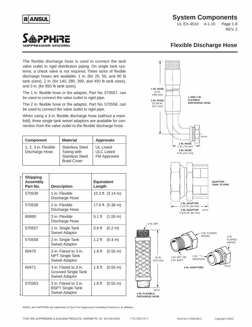
The flexible discharge hose is used to connect the tankvalve outlet to rigid distribution piping. On single tank sys-tems, a check valve is not required. Three sizes of flexibledischarge hoses are available: 1 in. (for 20, 50, and 90 lbtank sizes), 2 in. (for 140, 280, 390, and 450 lb tank sizes),and 3 in. (for 850 lb tank sizes).
The 1 in. flexible hose or the adaptor, Part No. 570557, canbe used to connect the valve outlet to rigid pipe.
The 2 in. flexible hose or the adaptor, Part No. 570558, canbe used to connect the valve outlet to rigid pipe.
When using a 3 in. flexible discharge hose (without a mani-fold), three single tank swivel adaptors are available for con-nection from the valve outlet to the flexible discharge hose.
Flexible Discharge Hose
TYCO FIRE SUPPRESSION & BUILDING PRODUCTS, MARINETTE, WI 54143-2542 715-735-7411 Form No. F-2003190-2 Copyright ©2010
ANSUL and SAPPHIRE are trademarks of Tyco Fire Suppression & Building Products or its affiliates.
Component Material Approvals
1, 2, 3 in. Flexible Stainless Steel UL ListedDischarge Hose Tubing with ULC Listed
Stainless Steel FM ApprovedBraid Cover
ShippingAssembly EquivalentPart No. Description Length
570539 1 in. Flexible 10.3 ft (3.14 m)Discharge Hose
570538 2 in. Flexible 17.6 ft (5.36 m)Discharge Hose
69990 3 in. Flexible 5.1 ft (1.55 m)Discharge Hose
570557 1 in. Single Tank 0.6 ft (0.2 m)Swivel Adaptor
570558 2 in. Single Tank 1.2 ft (0.4 m)Swivel Adaptor
69470 3 in. Flared to 3 in. 1.8 ft (0.55 m)NPT Single TankSwivel Adaptor
69471 3 in. Flared to 3 in. 1.8 ft (0.55 m)Grooved Single TankSwivel Adaptor
570363 3 in. Flared to 3 in. 1.8 ft (0.55 m)BSPT Single TankSwivel Adaptor
006760
006760
006249
006248
3 IN. FLEXIBLEDISCHARGE HOSE
3 IN. ADAPTORS
ADAPTOR –TANK TO PIPE
1 AND 2 IN.FLEXIBLEDISCHARGE HOSE
16 IN.(410 mm)
3 IN. NPT
3 IN. FLAREDSWIVEL 3 IN.
FLAREDSWIVEL
3 IN.GROOVED
3 IN. NPT OR3 IN. BSPT
1 IN. ADAPTOR2 1/2 IN. (64 mm)
2 IN. ADAPTOR3 3/16 IN. (81 mm)
1 IN. HOSE3 IN. (79 mm)
2 IN. HOSE5 IN. (127 mm)
1 IN. HOSE16 IN.
(406 mm)
2 IN. HOSE20 3/8 IN.(517 mm)
System ComponentsUL EX-4510 4-1-10 Page 1-9
REV. 2
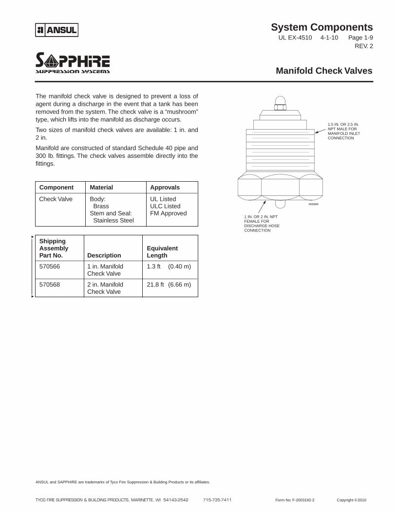
The manifold check valve is designed to prevent a loss ofagent during a discharge in the event that a tank has beenremoved from the system. The check valve is a “mushroom”type, which lifts into the manifold as discharge occurs.
Two sizes of manifold check valves are available: 1 in. and2 in.
Manifold are constructed of standard Schedule 40 pipe and300 lb. fittings. The check valves assemble directly into thefittings.
Manifold Check Valves
TYCO FIRE SUPPRESSION & BUILDING PRODUCTS, MARINETTE, WI 54143-2542 715-735-7411 Form No. F-2003192-2 Copyright ©2010
ANSUL and SAPPHIRE are trademarks of Tyco Fire Suppression & Building Products or its affiliates.
ShippingAssembly EquivalentPart No. Description Length
570566 1 in. Manifold 1.3 ft (0.40 m)Check Valve
570568 2 in. Manifold 21.8 ft (6.66 m)Check Valve
Component Material Approvals
Check Valve Body: UL ListedBrass ULC Listed
Stem and Seal: FM ApprovedStainless Steel
006889
1.5 IN. OR 2.5 IN.NPT MALE FORMANIFOLD INLETCONNECTION
1 IN. OR 2 IN. NPTFEMALE FORDISCHARGE HOSECONNECTION
System ComponentsUL EX-4510 4-1-10 Page 1-10
REV. 1
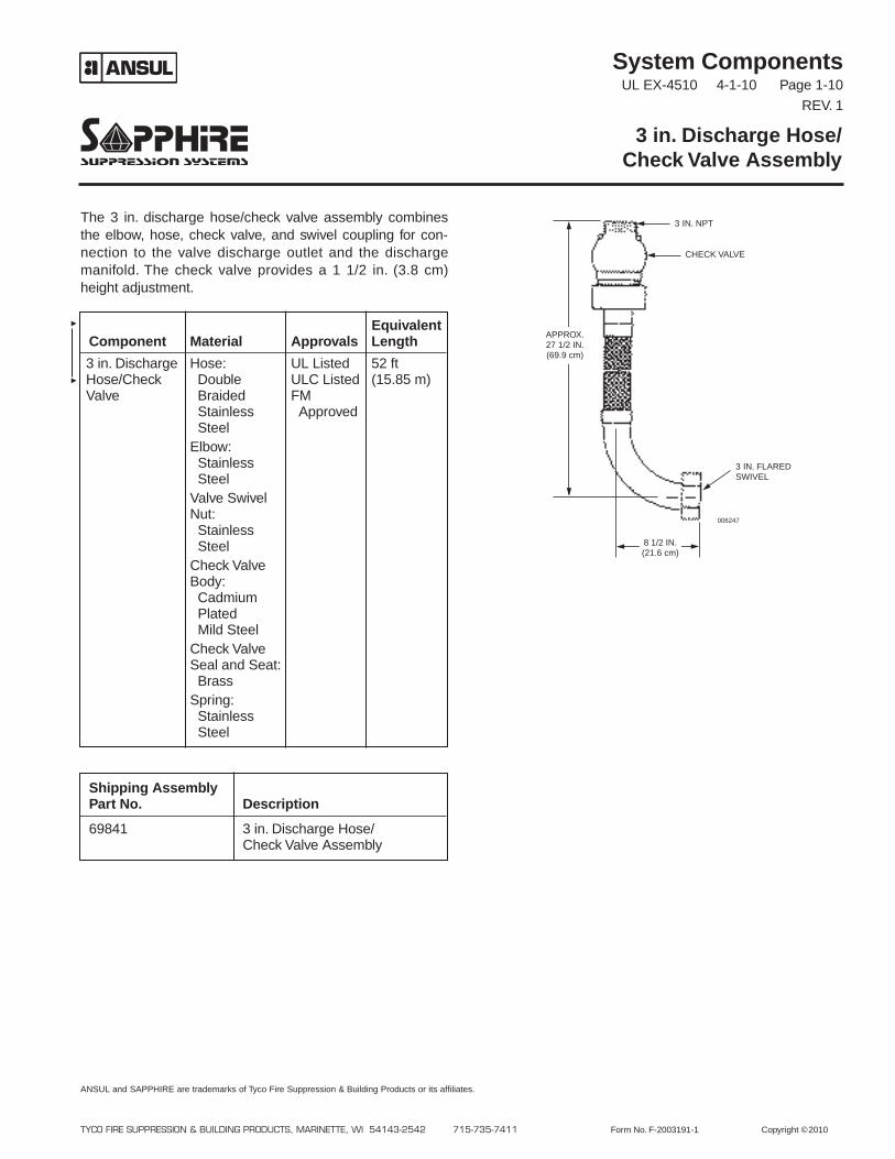
The 3 in. discharge hose/check valve assembly combinesthe elbow, hose, check valve, and swivel coupling for con-nection to the valve discharge outlet and the dischargemanifold. The check valve provides a 1 1/2 in. (3.8 cm)height adjustment.
3 in. Discharge Hose/Check Valve Assembly
TYCO FIRE SUPPRESSION & BUILDING PRODUCTS, MARINETTE, WI 54143-2542 715-735-7411 Form No. F-2003191-1 Copyright ©2010
ANSUL and SAPPHIRE are trademarks of Tyco Fire Suppression & Building Products or its affiliates.
Shipping AssemblyPart No. Description
69841 3 in. Discharge Hose/Check Valve Assembly
EquivalentComponent Material Approvals Length
3 in. Discharge Hose: UL Listed 52 ftHose/Check Double ULC Listed (15.85 m)Valve Braided FM
Stainless ApprovedSteel
Elbow:StainlessSteel
Valve SwivelNut:StainlessSteel
Check ValveBody:CadmiumPlatedMild Steel
Check ValveSeal and Seat:Brass
Spring:StainlessSteel
3 IN. FLAREDSWIVEL
3 IN. NPT
CHECK VALVE
006247
8 1/2 IN.(21.6 cm)
APPROX.27 1/2 IN.(69.9 cm)
System ComponentsUL EX-4510 9-1-10 Page 1-11
REV. 2
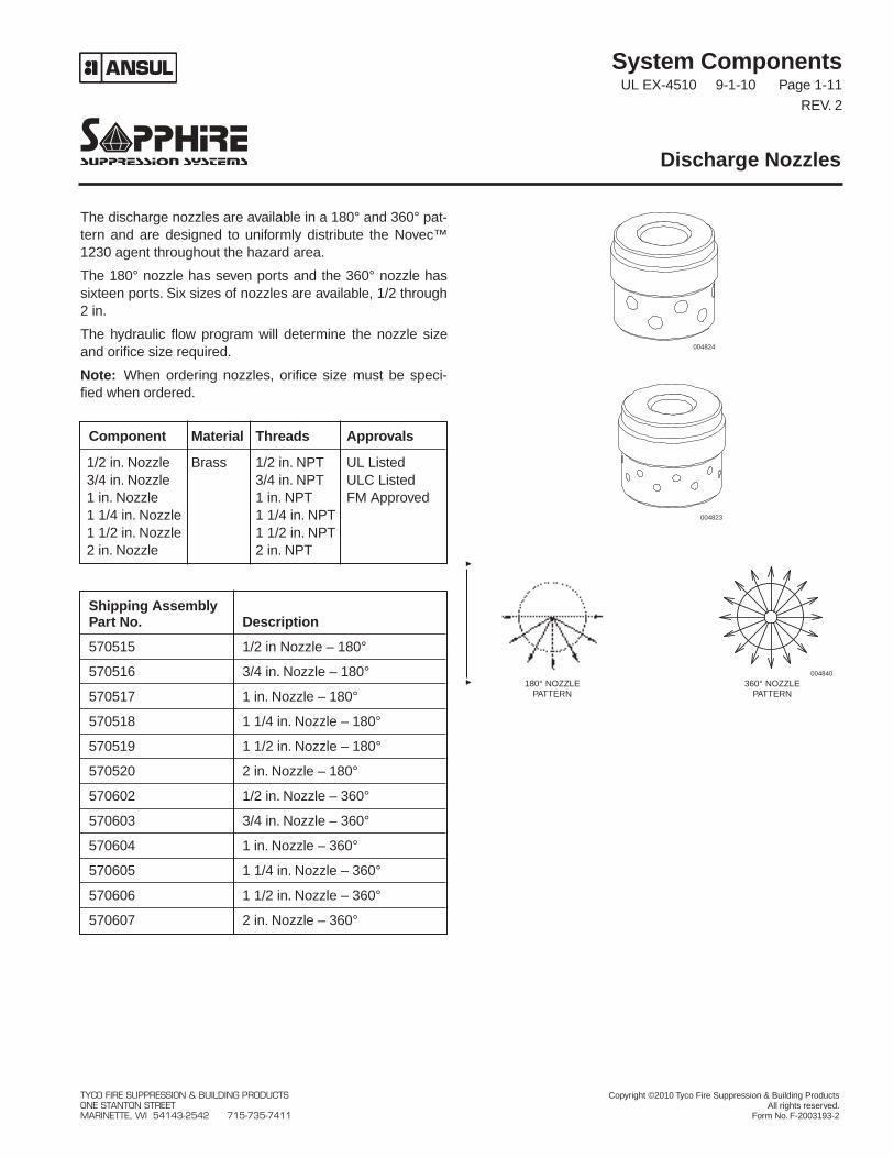
The discharge nozzles are available in a 180° and 360° pat-tern and are designed to uniformly distribute the Novec™1230 agent throughout the hazard area.
The 180° nozzle has seven ports and the 360° nozzle hassixteen ports. Six sizes of nozzles are available, 1/2 through2 in.
The hydraulic flow program will determine the nozzle sizeand orifice size required.
Note: When ordering nozzles, orifice size must be speci-fied when ordered.
Discharge Nozzles
Shipping AssemblyPart No. Description
570515 1/2 in Nozzle – 180°
570516 3/4 in. Nozzle – 180°
570517 1 in. Nozzle – 180°
570518 1 1/4 in. Nozzle – 180°
570519 1 1/2 in. Nozzle – 180°
570520 2 in. Nozzle – 180°
570602 1/2 in. Nozzle – 360°
570603 3/4 in. Nozzle – 360°
570604 1 in. Nozzle – 360°
570605 1 1/4 in. Nozzle – 360°
570606 1 1/2 in. Nozzle – 360°
570607 2 in. Nozzle – 360°
Component Material Threads Approvals
1/2 in. Nozzle Brass 1/2 in. NPT UL Listed3/4 in. Nozzle 3/4 in. NPT ULC Listed1 in. Nozzle 1 in. NPT FM Approved1 1/4 in. Nozzle 1 1/4 in. NPT1 1/2 in. Nozzle 1 1/2 in. NPT2 in. Nozzle 2 in. NPT
004824
004823
004840
180° NOZZLEPATTERN
360° NOZZLEPATTERN
TYCO FIRE SUPPRESSION & BUILDING PRODUCTS Copyright ©2010 Tyco Fire Suppression & Building ProductsONE STANTON STREET All rights reserved.MARINETTE, WI 54143-2542 715-735-7411 Form No. F-2003193-2
System ComponentsUL EX-4510 12-1-03 Page 1-12
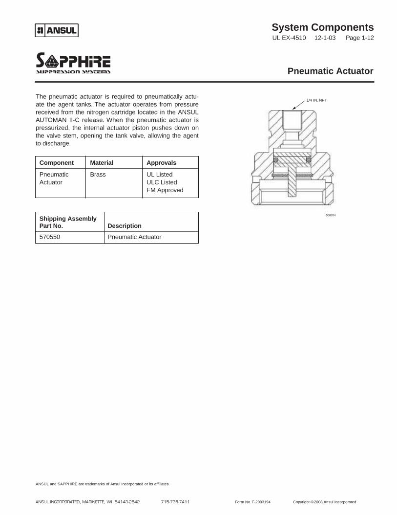
The pneumatic actuator is required to pneumatically actu-ate the agent tanks. The actuator operates from pressurereceived from the nitrogen cartridge located in the ANSULAUTOMAN II-C release. When the pneumatic actuator ispressurized, the internal actuator piston pushes down onthe valve stem, opening the tank valve, allowing the agentto discharge.
Pneumatic Actuator
ANSUL INCORPORATED, MARINETTE, WI 54143-2542 715-735-7411 Form No. F-2003194 Copyright ©2008 Ansul Incorporated
ANSUL and SAPPHIRE are trademarks of Ansul Incorporated or its affiliates.
Shipping AssemblyPart No. Description
570550 Pneumatic Actuator
Component Material Approvals
Pneumatic Brass UL ListedActuator ULC Listed
FM Approved
006764
1/4 IN. NPT
System ComponentsUL EX-4510 12-1-03 Page 1-13
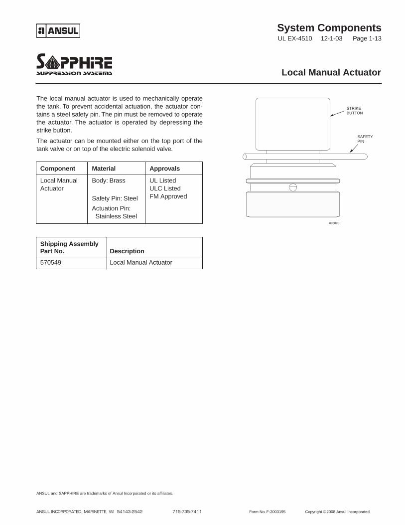
The local manual actuator is used to mechanically operatethe tank. To prevent accidental actuation, the actuator con-tains a steel safety pin. The pin must be removed to operatethe actuator. The actuator is operated by depressing thestrike button.
The actuator can be mounted either on the top port of thetank valve or on top of the electric solenoid valve.
Local Manual Actuator
ANSUL INCORPORATED, MARINETTE, WI 54143-2542 715-735-7411 Form No. F-2003195 Copyright ©2008 Ansul Incorporated
ANSUL and SAPPHIRE are trademarks of Ansul Incorporated or its affiliates.
Shipping AssemblyPart No. Description
570549 Local Manual Actuator
Component Material Approvals
Local Manual Body: Brass UL ListedActuator ULC Listed
Safety Pin: Steel FM Approved
Actuation Pin:Stainless Steel
006890
STRIKEBUTTON
SAFETYPIN
System ComponentsUL EX-4510 12-1-03 Page 1-14
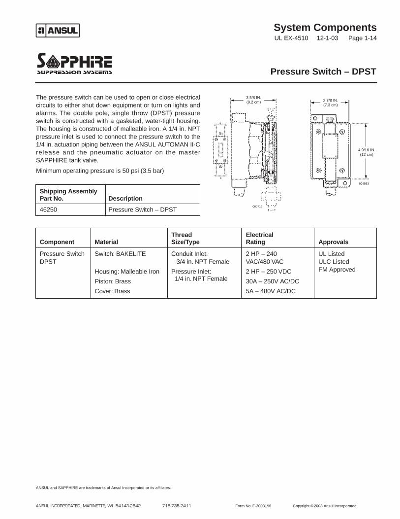
The pressure switch can be used to open or close electricalcircuits to either shut down equipment or turn on lights andalarms. The double pole, single throw (DPST) pressureswitch is constructed with a gasketed, water-tight housing.The housing is constructed of malleable iron. A 1/4 in. NPTpressure inlet is used to connect the pressure switch to the1/4 in. actuation piping between the ANSUL AUTOMAN II-Crelease and the pneumatic actuator on the masterSAPPHIRE tank valve.
Minimum operating pressure is 50 psi (3.5 bar)
Pressure Switch – DPST
ANSUL INCORPORATED, MARINETTE, WI 54143-2542 715-735-7411 Form No. F-2003196 Copyright ©2008 Ansul Incorporated
ANSUL and SAPPHIRE are trademarks of Ansul Incorporated or its affiliates.
Thread ElectricalComponent Material Size/Type Rating Approvals
Pressure Switch Switch: BAKELITE Conduit Inlet: 2 HP – 240 UL ListedDPST 3/4 in. NPT Female VAC/480 VAC ULC Listed
Housing: Malleable Iron Pressure Inlet: 2 HP – 250 VDC FM Approved
Piston: Brass 1/4 in. NPT Female 30A – 250V AC/DC
Cover: Brass 5A – 480V AC/DC
000716
004593
Shipping AssemblyPart No. Description
46250 Pressure Switch – DPST
3 5/8 IN.(9.2 cm) 2 7/8 IN.
(7.3 cm)
4 9/16 IN.(12 cm)
System ComponentsUL EX-4510 9-1-10 Page 1-15
REV. 3
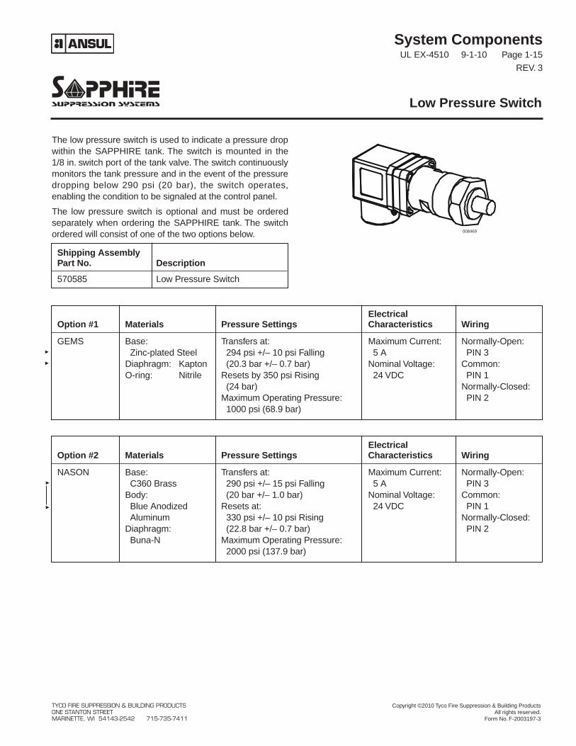
The low pressure switch is used to indicate a pressure dropwithin the SAPPHIRE tank. The switch is mounted in the1/8 in. switch port of the tank valve. The switch continuouslymonitors the tank pressure and in the event of the pressuredropping below 290 psi (20 bar), the switch operates,enabling the condition to be signaled at the control panel.
The low pressure switch is optional and must be orderedseparately when ordering the SAPPHIRE tank. The switchordered will consist of one of the two options below.
Low Pressure Switch
ElectricalOption #1 Materials Pressure Settings Characteristics Wiring
GEMS Base: Transfers at: Maximum Current: Normally-Open:Zinc-plated Steel 294 psi +/– 10 psi Falling 5 A PIN 3
Diaphragm: Kapton (20.3 bar +/– 0.7 bar) Nominal Voltage: Common:O-ring: Nitrile Resets by 350 psi Rising 24 VDC PIN 1
(24 bar) Normally-Closed:Maximum Operating Pressure: PIN 21000 psi (68.9 bar)
ElectricalOption #2 Materials Pressure Settings Characteristics Wiring
NASON Base: Transfers at: Maximum Current: Normally-Open:C360 Brass 290 psi +/– 15 psi Falling 5 A PIN 3
Body: (20 bar +/– 1.0 bar) Nominal Voltage: Common:Blue Anodized Resets at: 24 VDC PIN 1Aluminum 330 psi +/– 10 psi Rising Normally-Closed:
Diaphragm: (22.8 bar +/– 0.7 bar) PIN 2Buna-N Maximum Operating Pressure:
2000 psi (137.9 bar)
008469
Shipping AssemblyPart No. Description
570585 Low Pressure Switch
TYCO FIRE SUPPRESSION & BUILDING PRODUCTS Copyright ©2010 Tyco Fire Suppression & Building ProductsONE STANTON STREET All rights reserved.MARINETTE, WI 54143-2542 715-735-7411 Form No. F-2003197-3
System ComponentsUL EX-4510 12-1-03 Page 1-16
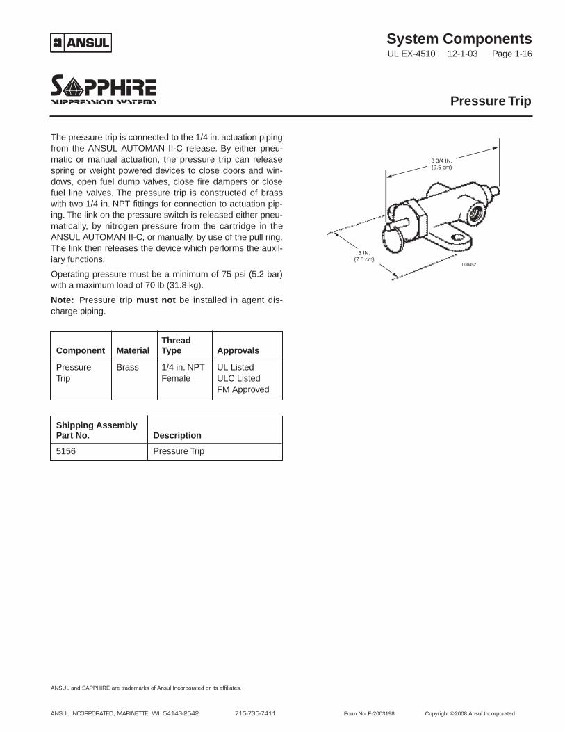
The pressure trip is connected to the 1/4 in. actuation pipingfrom the ANSUL AUTOMAN II-C release. By either pneu-matic or manual actuation, the pressure trip can releasespring or weight powered devices to close doors and win-dows, open fuel dump valves, close fire dampers or closefuel line valves. The pressure trip is constructed of brasswith two 1/4 in. NPT fittings for connection to actuation pip-ing. The link on the pressure switch is released either pneu-matically, by nitrogen pressure from the cartridge in theANSUL AUTOMAN II-C, or manually, by use of the pull ring.The link then releases the device which performs the auxil-iary functions.
Operating pressure must be a minimum of 75 psi (5.2 bar)with a maximum load of 70 lb (31.8 kg).
Note: Pressure trip must not be installed in agent dis-charge piping.
Pressure Trip
ANSUL INCORPORATED, MARINETTE, WI 54143-2542 715-735-7411 Form No. F-2003198 Copyright ©2008 Ansul Incorporated
ANSUL and SAPPHIRE are trademarks of Ansul Incorporated or its affiliates.
Shipping AssemblyPart No. Description
5156 Pressure Trip
ThreadComponent Material Type Approvals
Pressure Brass 1/4 in. NPT UL ListedTrip Female ULC Listed
FM Approved
000452
3 IN.(7.6 cm)
3 3/4 IN.(9.5 cm)
System ComponentsUL EX-4510 12-1-03 Page 1-17
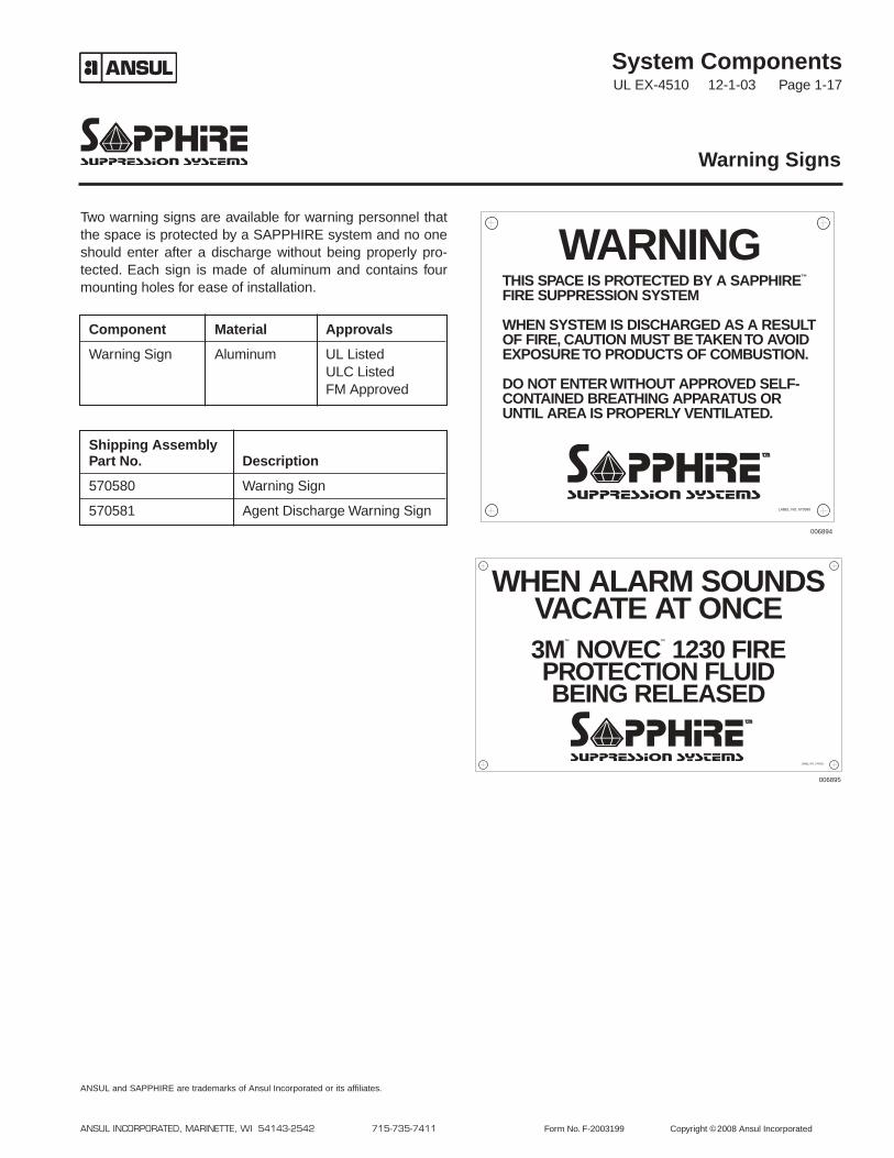
Two warning signs are available for warning personnel thatthe space is protected by a SAPPHIRE system and no oneshould enter after a discharge without being properly pro-tected. Each sign is made of aluminum and contains fourmounting holes for ease of installation.
Warning Signs
ANSUL INCORPORATED, MARINETTE, WI 54143-2542 715-735-7411 Form No. F-2003199 Copyright ©2008 Ansul Incorporated
ANSUL and SAPPHIRE are trademarks of Ansul Incorporated or its affiliates.
Component Material Approvals
Warning Sign Aluminum UL ListedULC ListedFM Approved
Shipping AssemblyPart No. Description
570580 Warning Sign
570581 Agent Discharge Warning Sign LABEL NO. 570580
WARNINGTHIS SPACE IS PROTECTED BY A SAPPHIRE™
FIRE SUPPRESSION SYSTEM
WHEN SYSTEM IS DISCHARGED AS A RESULTOF FIRE, CAUTION MUST BE TAKEN TO AVOIDEXPOSURE TO PRODUCTS OF COMBUSTION.
DO NOT ENTER WITHOUT APPROVED SELF-CONTAINED BREATHING APPARATUS ORUNTIL AREA IS PROPERLY VENTILATED.
LABEL NO. 570581
WHEN ALARM SOUNDSVACATE AT ONCE3M
™
NOVEC™
1230 FIREPROTECTION FLUIDBEING RELEASED
006895
006894
System ComponentsUL EX-4510 12-1-03 Page 1-18
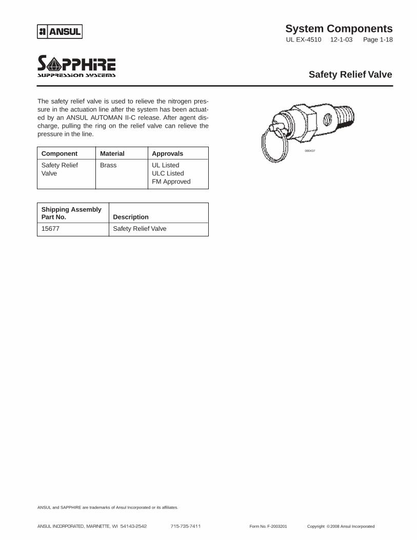
The safety relief valve is used to relieve the nitrogen pres-sure in the actuation line after the system has been actuat-ed by an ANSUL AUTOMAN II-C release. After agent dis-charge, pulling the ring on the relief valve can relieve thepressure in the line.
Safety Relief Valve
ANSUL INCORPORATED, MARINETTE, WI 54143-2542 715-735-7411 Form No. F-2003201 Copyright ©2008 Ansul Incorporated
ANSUL and SAPPHIRE are trademarks of Ansul Incorporated or its affiliates.
Component Material Approvals
Safety Relief Brass UL ListedValve ULC Listed
FM Approved
Shipping AssemblyPart No. Description
15677 Safety Relief Valve
000437
System ComponentsUL EX-4510 9-1-10 Page 1-19
REV. 1
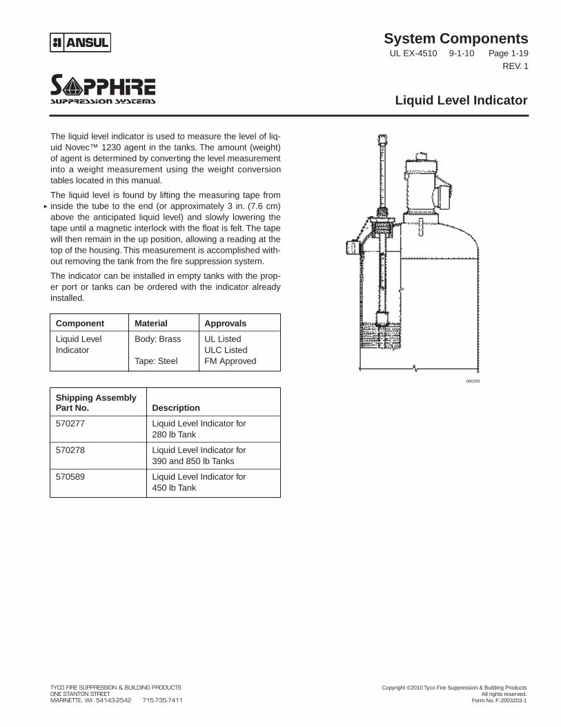
The liquid level indicator is used to measure the level of liq-uid Novec™ 1230 agent in the tanks. The amount (weight)of agent is determined by converting the level measurementinto a weight measurement using the weight conversiontables located in this manual.
The liquid level is found by lifting the measuring tape frominside the tube to the end (or approximately 3 in. (7.6 cm)above the anticipated liquid level) and slowly lowering thetape until a magnetic interlock with the float is felt. The tapewill then remain in the up position, allowing a reading at thetop of the housing. This measurement is accomplished with-out removing the tank from the fire suppression system.
The indicator can be installed in empty tanks with the prop-er port or tanks can be ordered with the indicator alreadyinstalled.
Liquid Level Indicator
Component Material Approvals
Liquid Level Body: Brass UL ListedIndicator ULC Listed
Tape: Steel FM Approved
Shipping AssemblyPart No. Description
570277 Liquid Level Indicator for280 lb Tank
570278 Liquid Level Indicator for390 and 850 lb Tanks
570589 Liquid Level Indicator for450 lb Tank
006255
TYCO FIRE SUPPRESSION & BUILDING PRODUCTS Copyright ©2010 Tyco Fire Suppression & Building ProductsONE STANTON STREET All rights reserved.MARINETTE, WI 54143-2542 715-735-7411 Form No. F-2003203-1
System ComponentsUL EX-4510 4-1-05 Page 1-20
REV. 1
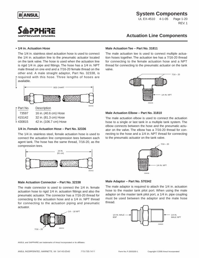
1/4 in. Actuation Hose
The 1/4 in. stainless steel actuation hose is used to connectthe 1/4 in. actuation line to the pneumatic actuator locatedon the tank valve. The hose is used when the actuation lineis rigid 1/4 in. pipe and fittings. The hose has a 1/4 in. NPTmale thread on one end and a 7/16-20 female thread on theother end. A male straight adaptor, Part No. 32338, isrequired with this hose. Three lengths of hoses areavailable.
Part No. Description______ _________
73597 16 in. (40.6 cm) Hose415142 32 in. (81.3 cm) Hose430815 42 in. (106.7 cm) Hose
1/4 in. Female Actuation Hose – Part No. 32336
The 1/4 in. stainless steel, female actuation hose is used toconnect the actuation line compression tees between eachagent tank. The hose has the same thread, 7/16-20, as thecompression tees.
Male Actuation Connector – Part No. 32338
The male connector is used to connect the 1/4 in. femaleactuation hose to rigid 1/4 in. actuation fittings and also thepneumatic actuator. The connector has a 7/16-20 thread forconnecting to the actuation hose and a 1/4 in. NPT threadfor connecting to the actuation piping and pneumaticactuator.
Male Actuation Tee – Part No. 31811
The male actuation tee is used to connect multiple actua-tion hoses together. The actuation tee has a 7/16-20 threadfor connecting to the female actuation hose and a NPTthread for connecting to the pneumatic actuator on the tankvalve.
Male Actuation Elbow – Part No. 31810
The male actuation elbow is used to connect the actuationhose to a single or last tank in a multiple tank system. Theelbow connects between the hose and the pneumatic actu-ator on the valve. The elbow has a 7/16-20 thread for con-necting to the hose and a 1/4 in. NPT thread for connectingto the pneumatic actuator on the tank valve.
Male Adaptor – Part No. 570342
The male adaptor is required to attach the 1/4 in. actuationhose to the master tank pilot port. When using the maleadaptor on the master tank pilot port, a 1/4 in. pipe couplingmust be used between the adaptor and the male hosethread.
Actuation Line Components
ANSUL INCORPORATED, MARINETTE, WI 54143-2542 715-735-7411 Form No. F-2003200-1 Copyright ©2008 Ansul Incorporated
ANSUL and SAPPHIRE are trademarks of Ansul Incorporated or its affiliates.
000432
000435
000436
000433
000434
SEE CHART
24 IN.(61 cm)
7/16 – 20
1/4 – 18 NPT
1/4 IN. NPT
1/4 IN. NPT
7/16 – 20
7/16 – 20
004820
1/4 IN.MALE NPT
1/4 IN. MALEBSP
System ComponentsUL EX-4510 12-1-03 Page 1-21
Recharge and rebuild tools and kits are available for disas-sembling the valves after a discharge. O-ring kits are avail-able to replace internal valve o-rings after a discharge.
Spanner Wrench – Part No. 570574
This tool is required to remove the valve bonnet assemblyfor access to the valve piston and o-ring replacement on 1and 2 in. valves.
Recharge Adaptors
Top Adaptor Assembly for 1 and 2 in. Valves – Part No.570579
Fill Adaptor Assembly for 1 in. Valve – Part No. 570576
Fill Adaptor Assembly for 2 in. Valve – Part No. 570592
Fill Adaptor Assembly for 3 in. Valve – Part No. 69891
Rebuild Kits
Rebuild Kit for 1 in. Valve – Part No. 570559 (containsbonnet o-ring, collar o-ring, siphon tube o-ring)
Rebuild Kit for 2 in. Valve – Part No. 570584 (containsbonnet o-ring, collar o-ring, siphon tube o-ring)
Rebuild Kit for 3 in. Valve – Part No. 570373 (contains topcap o-ring, complete piston assembly, collar o-ring)
Recharge Components
ANSUL INCORPORATED, MARINETTE, WI 54143-2542 715-735-7411 Form No. F-2003232 Copyright ©2008 Ansul Incorporated
ANSUL and SAPPHIRE are trademarks of Ansul Incorporated or its affiliates.
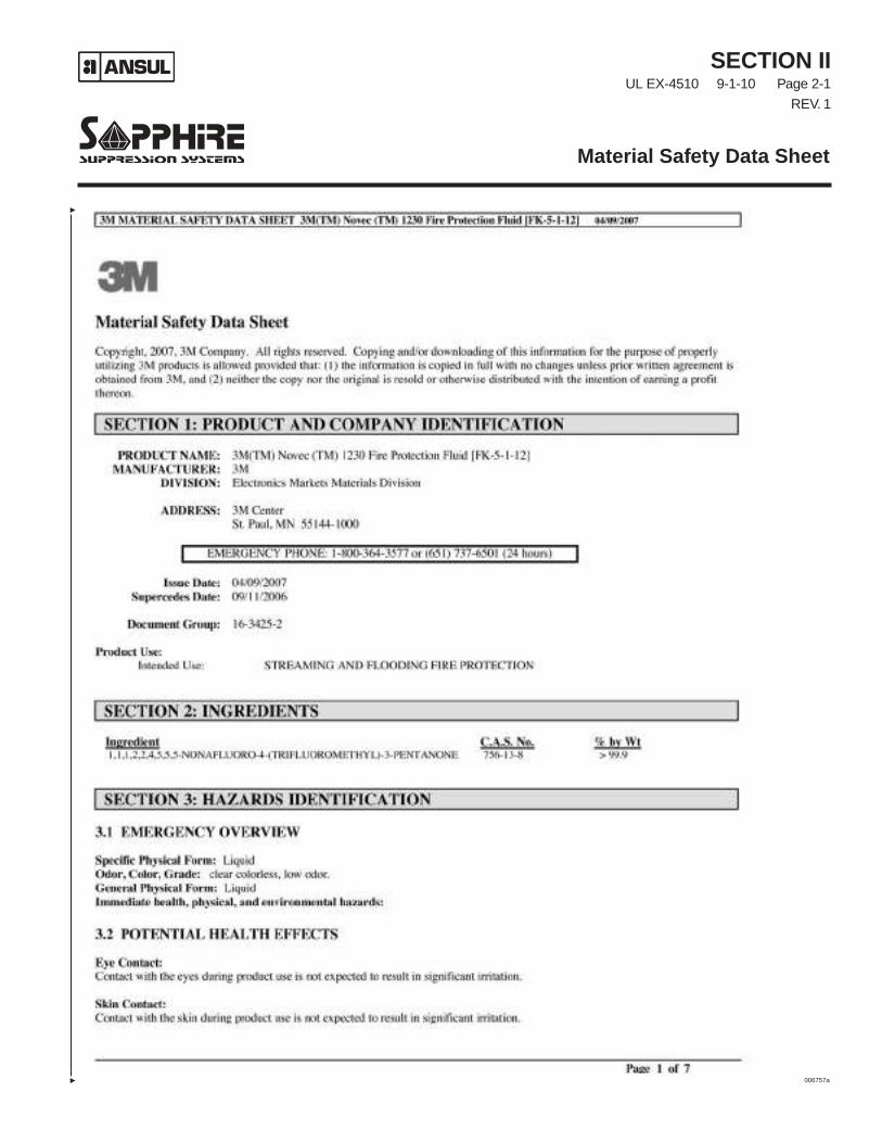
SECTION IIUL EX-4510 9-1-10 Page 2-1
REV. 1
Material Safety Data Sheet
006757a
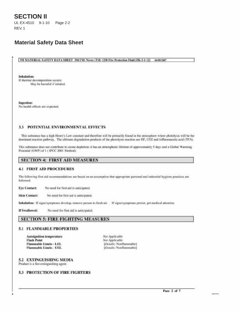
SECTION IIUL EX-4510 9-1-10 Page 2-2
REV. 1
Material Safety Data Sheet
006757b
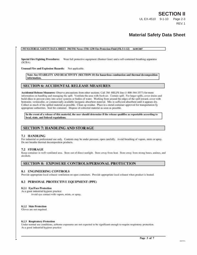
SECTION IIUL EX-4510 9-1-10 Page 2-3
REV. 1
Material Safety Data Sheet
006757c
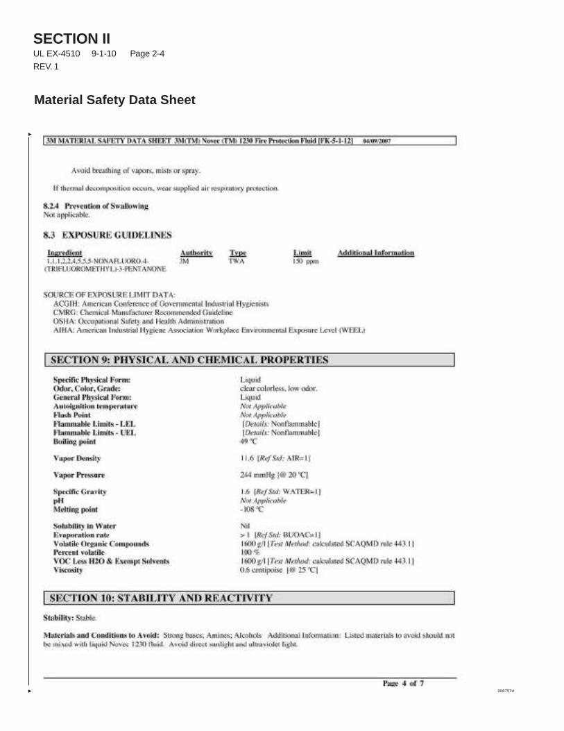
SECTION IIUL EX-4510 9-1-10 Page 2-4
REV. 1
Material Safety Data Sheet
006757d
SECTION IIUL EX-4510 9-1-10 Page 2-5
REV. 1
Material Safety Data Sheet
006757e
SECTION IIUL EX-4510 9-1-10 Page 2-6
REV. 1
Material Safety Data Sheet
006757f
SECTION IIUL EX-4510 9-1-10 Page 2-7
Material Safety Data Sheet
006757g

SECTION IIUL EX-4510 9-1-10 Page 2-8
Material Safety Data Sheet
NOTES:
SECTION IIIUL EX-4510 12-1-03 Page 3-1
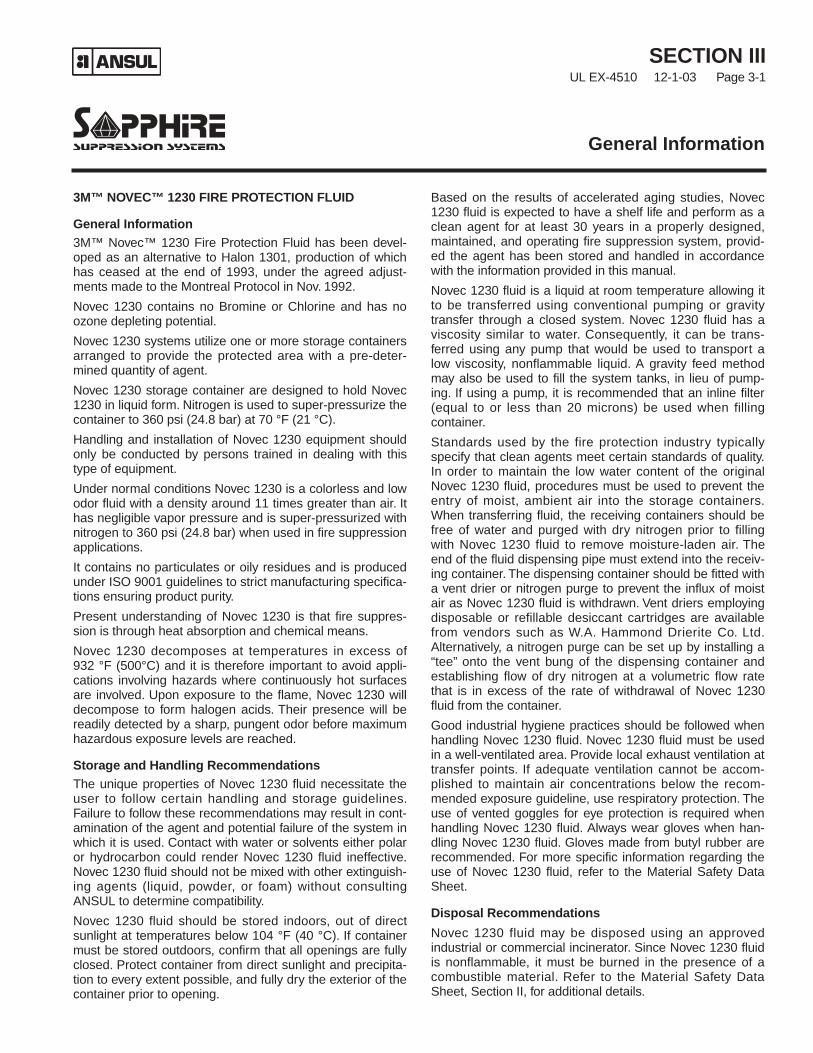
3M™ NOVEC™ 1230 FIRE PROTECTION FLUID
General Information3M™ Novec™ 1230 Fire Protection Fluid has been devel-oped as an alternative to Halon 1301, production of whichhas ceased at the end of 1993, under the agreed adjust-ments made to the Montreal Protocol in Nov. 1992.
Novec 1230 contains no Bromine or Chlorine and has noozone depleting potential.
Novec 1230 systems utilize one or more storage containersarranged to provide the protected area with a pre-deter-mined quantity of agent.
Novec 1230 storage container are designed to hold Novec1230 in liquid form. Nitrogen is used to super-pressurize thecontainer to 360 psi (24.8 bar) at 70 °F (21 °C).
Handling and installation of Novec 1230 equipment shouldonly be conducted by persons trained in dealing with thistype of equipment.
Under normal conditions Novec 1230 is a colorless and lowodor fluid with a density around 11 times greater than air. Ithas negligible vapor pressure and is super-pressurized withnitrogen to 360 psi (24.8 bar) when used in fire suppressionapplications.
It contains no particulates or oily residues and is producedunder ISO 9001 guidelines to strict manufacturing specifica-tions ensuring product purity.
Present understanding of Novec 1230 is that fire suppres-sion is through heat absorption and chemical means.
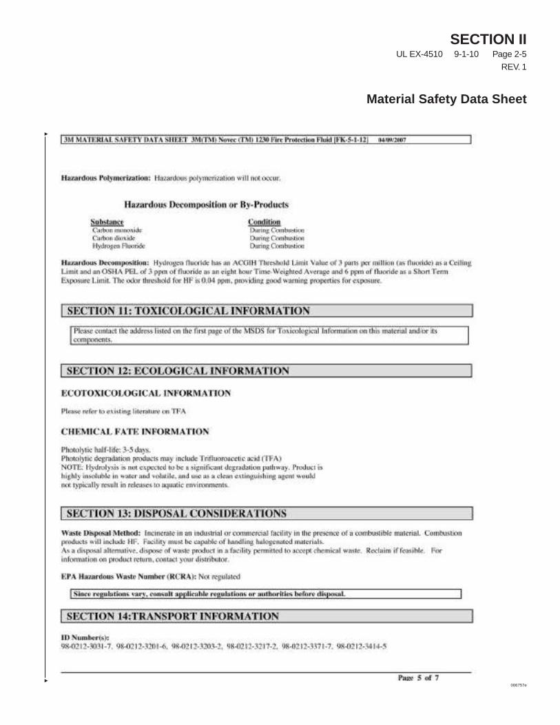
Novec 1230 decomposes at temperatures in excess of932 °F (500°C) and it is therefore important to avoid appli-cations involving hazards where continuously hot surfacesare involved. Upon exposure to the flame, Novec 1230 willdecompose to form halogen acids. Their presence will bereadily detected by a sharp, pungent odor before maximumhazardous exposure levels are reached.
Storage and Handling RecommendationsThe unique properties of Novec 1230 fluid necessitate theuser to follow certain handling and storage guidelines.Failure to follow these recommendations may result in cont-amination of the agent and potential failure of the system inwhich it is used. Contact with water or solvents either polaror hydrocarbon could render Novec 1230 fluid ineffective.Novec 1230 fluid should not be mixed with other extinguish-ing agents (liquid, powder, or foam) without consultingANSUL to determine compatibility.
Novec 1230 fluid should be stored indoors, out of directsunlight at temperatures below 104 °F (40 °C). If containermust be stored outdoors, confirm that all openings are fullyclosed. Protect container from direct sunlight and precipita-tion to every extent possible, and fully dry the exterior of thecontainer prior to opening.
Based on the results of accelerated aging studies, Novec1230 fluid is expected to have a shelf life and perform as aclean agent for at least 30 years in a properly designed,maintained, and operating fire suppression system, provid-ed the agent has been stored and handled in accordancewith the information provided in this manual.
Novec 1230 fluid is a liquid at room temperature allowing itto be transferred using conventional pumping or gravitytransfer through a closed system. Novec 1230 fluid has aviscosity similar to water. Consequently, it can be trans-ferred using any pump that would be used to transport alow viscosity, nonflammable liquid. A gravity feed methodmay also be used to fill the system tanks, in lieu of pump-ing. If using a pump, it is recommended that an inline filter(equal to or less than 20 microns) be used when fillingcontainer.
Standards used by the fire protection industry typicallyspecify that clean agents meet certain standards of quality.In order to maintain the low water content of the originalNovec 1230 fluid, procedures must be used to prevent theentry of moist, ambient air into the storage containers.When transferring fluid, the receiving containers should befree of water and purged with dry nitrogen prior to fillingwith Novec 1230 fluid to remove moisture-laden air. Theend of the fluid dispensing pipe must extend into the receiv-ing container. The dispensing container should be fitted witha vent drier or nitrogen purge to prevent the influx of moistair as Novec 1230 fluid is withdrawn. Vent driers employingdisposable or refillable desiccant cartridges are availablefrom vendors such as W.A. Hammond Drierite Co. Ltd.Alternatively, a nitrogen purge can be set up by installing a“tee” onto the vent bung of the dispensing container andestablishing flow of dry nitrogen at a volumetric flow ratethat is in excess of the rate of withdrawal of Novec 1230fluid from the container.
Good industrial hygiene practices should be followed whenhandling Novec 1230 fluid. Novec 1230 fluid must be usedin a well-ventilated area. Provide local exhaust ventilation attransfer points. If adequate ventilation cannot be accom-plished to maintain air concentrations below the recom-mended exposure guideline, use respiratory protection. Theuse of vented goggles for eye protection is required whenhandling Novec 1230 fluid. Always wear gloves when han-dling Novec 1230 fluid. Gloves made from butyl rubber arerecommended. For more specific information regarding theuse of Novec 1230 fluid, refer to the Material Safety DataSheet.
Disposal Recommendations
Novec 1230 fluid may be disposed using an approvedindustrial or commercial incinerator. Since Novec 1230 fluidis nonflammable, it must be burned in the presence of acombustible material. Refer to the Material Safety DataSheet, Section II, for additional details.
General Information
SECTION IIIUL EX-4510 9-1-10 Page 3-2REV. 3
General Information
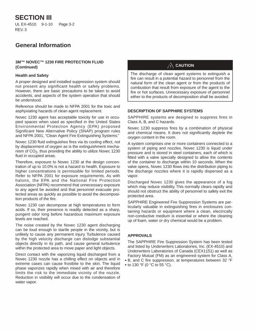
3M™ NOVEC™ 1230 FIRE PROTECTION FLUID(Continued)
Health and Safety
A proper designed and installed suppression system shouldnot present any significant health or safety problems.However, there are basic precautions to be taken to avoidaccidents, and aspects of the system operation that shouldbe understood.
Reference should be made to NFPA 2001 for the toxic andasphyxiating hazards of clean agent replacement.
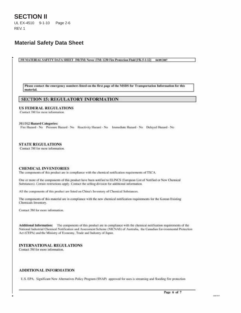
Novec 1230 agent has acceptable toxicity for use in occu-pied spaces when used as specified in the United StatesEnvironmental Protection Agency (EPA) proposedSignificant New Alternative Policy (SNAP) program rulesand NFPA 2001, “Clean Agent Fire Extinguishing Systems.”
Novec 1230 fluid extinguishes fires via its cooling effect, notby displacement of oxygen as is the extinguishment mecha-nism of CO2, thus providing the ability to utilize Novec 1230fluid in occupied areas.
Therefore, exposure to Novec 1230 at the design concen-tration of up to 10.0% is not a hazard to health. Exposure tohigher concentrations is permissible for limited periods.Refer to NFPA 2001 for exposure requirements. As withhalons, the EPA and the National Fire ProtectionAssociation (NFPA) recommend that unnecessary exposureto any agent be avoided and that personnel evacuate pro-tected areas as quickly as possible to avoid the decomposi-tion products of the fire.
Novec 1230 can decompose at high temperatures to formacids. If so, their presence is readily detected as a sharp,pungent odor long before hazardous maximum exposurelevels are reached.
The noise created by the Novec 1230 agent dischargingcan be loud enough to startle people in the vicinity, but isunlikely to cause any permanent injury. Turbulence causedby the high velocity discharge can dislodge substantialobjects directly in its path, and cause general turbulencewithin the protected area to move paper and light objects.
Direct contact with the vaporizing liquid discharged from aNovec 1230 nozzle has a chilling effect on objects and inextreme cases can cause frostbite to the skin. The liquidphase vaporizes rapidly when mixed with air and thereforelimits the risk to the immediate vicinity of the nozzle.Reduction in visibility will occur due to the condensation ofwater vapor.
DESCRIPTION OF SAPPHIRE SYSTEMS
SAPPHIRE systems are designed to suppress fires inClass A, B, and C hazards.
Novec 1230 suppress fires by a combination of physicaland chemical means. It does not significantly deplete theoxygen content in the room.
A system comprises one or more containers connected to asystem of piping and nozzles. Novec 1230 is liquid underpressure and is stored in steel containers, each of which isfitted with a valve specially designed to allow the contentsof the container to discharge within 10 seconds. When thevalve opens, Novec 1230 flows into the distribution piping tothe discharge nozzles where it is rapidly dispersed as avapor.
Discharged Novec 1230 gives the appearance of a fogwhich may reduce visibility. This normally clears rapidly andshould not obstruct the ability of personnel to safely exit theprotected area.
SAPPHIRE Engineered Fire Suppression Systems are par-ticularly valuable in extinguishing fires in enclosures con-taining hazards or equipment where a clean, electricallynon-conductive medium is essential or where the cleaningup of foam, water or dry chemical would be a problem.
APPROVALS
The SAPPHIRE Fire Suppression System has been testedand listed by Underwriters Laboratories, Inc. (EX-4510) andUnderwriters Laboratories of Canada (CEX1151) as well asFactory Mutual (FM) as an engineered system for Class A,B, and C fire suppression, at temperatures between 32 °Fto 130 °F (0 °C to 55 °C).
CAUTION!
The discharge of clean agent systems to extinguish afire can result in a potential hazard to personnel from thenatural form of the clean agent or from the products ofcombustion that result from exposure of the agent to thefire or hot surfaces. Unnecessary exposure of personneleither to the products of decomposition shall be avoided.
SECTION IIIUL EX-4510 12-1-03 Page 3-3
General Information
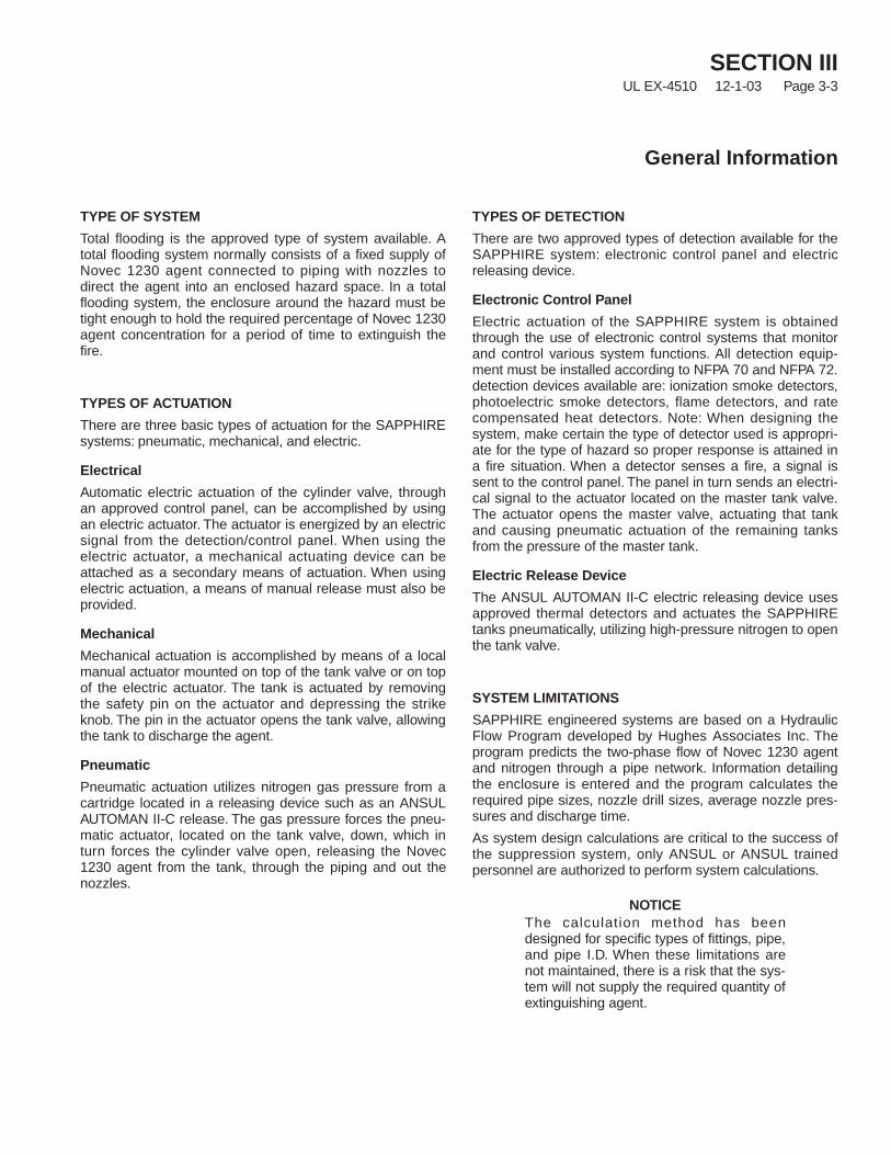
TYPE OF SYSTEM
Total flooding is the approved type of system available. Atotal flooding system normally consists of a fixed supply ofNovec 1230 agent connected to piping with nozzles todirect the agent into an enclosed hazard space. In a totalflooding system, the enclosure around the hazard must betight enough to hold the required percentage of Novec 1230agent concentration for a period of time to extinguish thefire.
TYPES OF ACTUATION
There are three basic types of actuation for the SAPPHIREsystems: pneumatic, mechanical, and electric.
Electrical
Automatic electric actuation of the cylinder valve, throughan approved control panel, can be accomplished by usingan electric actuator. The actuator is energized by an electricsignal from the detection/control panel. When using theelectric actuator, a mechanical actuating device can beattached as a secondary means of actuation. When usingelectric actuation, a means of manual release must also beprovided.
Mechanical
Mechanical actuation is accomplished by means of a localmanual actuator mounted on top of the tank valve or on topof the electric actuator. The tank is actuated by removingthe safety pin on the actuator and depressing the strikeknob. The pin in the actuator opens the tank valve, allowingthe tank to discharge the agent.
Pneumatic
Pneumatic actuation utilizes nitrogen gas pressure from acartridge located in a releasing device such as an ANSULAUTOMAN II-C release. The gas pressure forces the pneu-matic actuator, located on the tank valve, down, which inturn forces the cylinder valve open, releasing the Novec1230 agent from the tank, through the piping and out thenozzles.
TYPES OF DETECTION
There are two approved types of detection available for theSAPPHIRE system: electronic control panel and electricreleasing device.
Electronic Control Panel
Electric actuation of the SAPPHIRE system is obtainedthrough the use of electronic control systems that monitorand control various system functions. All detection equip-ment must be installed according to NFPA 70 and NFPA 72.detection devices available are: ionization smoke detectors,photoelectric smoke detectors, flame detectors, and ratecompensated heat detectors. Note: When designing thesystem, make certain the type of detector used is appropri-ate for the type of hazard so proper response is attained ina fire situation. When a detector senses a fire, a signal issent to the control panel. The panel in turn sends an electri-cal signal to the actuator located on the master tank valve.The actuator opens the master valve, actuating that tankand causing pneumatic actuation of the remaining tanksfrom the pressure of the master tank.
Electric Release Device
The ANSUL AUTOMAN II-C electric releasing device usesapproved thermal detectors and actuates the SAPPHIREtanks pneumatically, utilizing high-pressure nitrogen to openthe tank valve.
SYSTEM LIMITATIONS
SAPPHIRE engineered systems are based on a HydraulicFlow Program developed by Hughes Associates Inc. Theprogram predicts the two-phase flow of Novec 1230 agentand nitrogen through a pipe network. Information detailingthe enclosure is entered and the program calculates therequired pipe sizes, nozzle drill sizes, average nozzle pres-sures and discharge time.
As system design calculations are critical to the success ofthe suppression system, only ANSUL or ANSUL trainedpersonnel are authorized to perform system calculations.
NOTICEThe calculation method has beendesigned for specific types of fittings, pipe,and pipe I.D. When these limitations arenot maintained, there is a risk that the sys-tem will not supply the required quantity ofextinguishing agent.
SECTION IIIUL EX-4510 9-1-10 Page 3-4REV. 2
General Information
SYSTEM LIMITATIONS (Continued)
Design/Flow Calculation Limitations
• System Operating Temperature: 32 °F to 130 °F (0 °C to54 °C)
• Minimum Design Concentration: Class A, 4.2% – Class B,contact Ansul Technical Services for specific fuel designconcentrations
• Fill Density: Maximum 75 lb/ft3 (34.0 kg/m3), Minimum31.0 lb/ft3 (14.1 kg/m3)
• Discharge Time: Maximum 10 seconds, Minimum 6seconds
• Maximum Arrival Imbalance: 1 second
• Maximum Runout Imbalance: 2 seconds
• Maximum Pipe Volume to Cylinder Liquid Volume: 80%
• Minimum Pipe Volume Ratio Before First Tee: 10%
• Nozzle Area Ratio:
Maximum MinimumAll Size Nozzles 1/2 in. Nozzle All Other Sizes_____________ ___________ ____________80% 10% 20%
• Minimum Nozzle Pressure: 73 psi (5.0 bar)
• Flow Rate Limit:
Pipe Minimum Flow Rate Maximum Flow RateDiameter lb/s (kg/s) lb/s (kg/s)_______ ________________ ________________1/2 in. 1.0 (0.5) 3.0 (1.4)3/4 in. 2.0 (0.9) 5.5 (2.5)1 in. 3.5 (1.6) 8.5 (3.9)1 1/4 in. 6.0 (2.7) 12.5 (5.7)1 1/2 in. 9.0 (4.1) 20.0 (9.1)2 in. 14.0 (6.4) 30.0 (13.6)2 1/2 in. 20.0 (9.1) 55.0 (24.9)3 in. 30.0 (13.6) 90.0 (40.8)4 in. 55.0 (24.9) 125.0 (56.7)5 in. 90.0 (40.8) 200.0 (90.7)6 in. 120.0 (54.4) 300.0 (136.1)
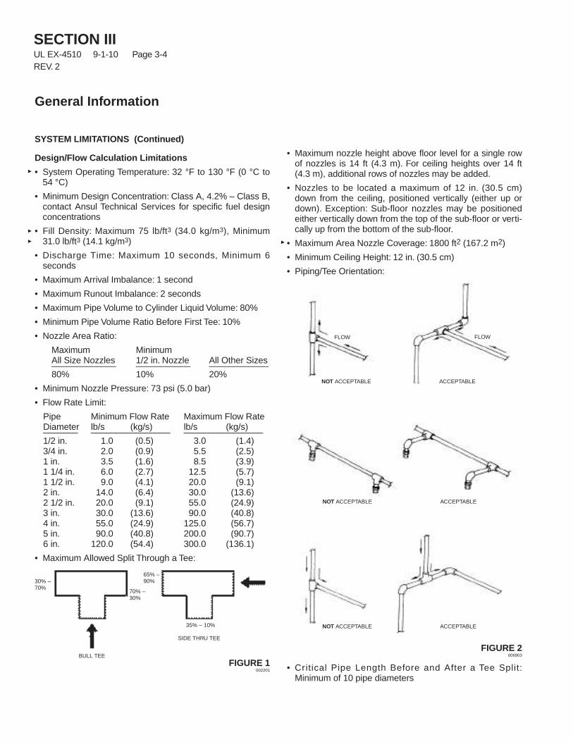
• Maximum Allowed Split Through a Tee:
FIGURE 1002201
• Maximum nozzle height above floor level for a single rowof nozzles is 14 ft (4.3 m). For ceiling heights over 14 ft(4.3 m), additional rows of nozzles may be added.
• Nozzles to be located a maximum of 12 in. (30.5 cm)down from the ceiling, positioned vertically (either up ordown). Exception: Sub-floor nozzles may be positionedeither vertically down from the top of the sub-floor or verti-cally up from the bottom of the sub-floor.
• Maximum Area Nozzle Coverage: 1800 ft2 (167.2 m2)
• Minimum Ceiling Height: 12 in. (30.5 cm)
• Piping/Tee Orientation:
FIGURE 2006903
• Critical Pipe Length Before and After a Tee Split:Minimum of 10 pipe diameters
FLOW FLOW
ACCEPTABLENOT ACCEPTABLE
ACCEPTABLENOT ACCEPTABLE
ACCEPTABLENOT ACCEPTABLE
SIDE THRU TEE
BULL TEE
30% –70%
65% –90%
70% –30%
35% – 10%
SECTION IIIUL EX-4510 4-1-05 Page 3-5
REV. 1
General Information
SYSTEM LIMITATIONS (Continued)
Design/Flow Calculation Limitations (Continued)
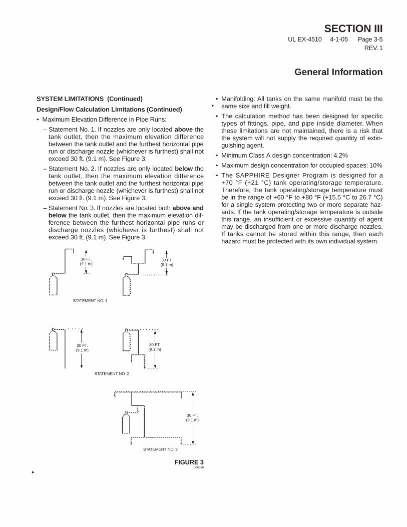
• Maximum Elevation Difference in Pipe Runs:
– Statement No. 1. If nozzles are only located above thetank outlet, then the maximum elevation differencebetween the tank outlet and the furthest horizontal piperun or discharge nozzle (whichever is furthest) shall notexceed 30 ft. (9.1 m). See Figure 3.
– Statement No. 2. If nozzles are only located below thetank outlet, then the maximum elevation differencebetween the tank outlet and the furthest horizontal piperun or discharge nozzle (whichever is furthest) shall notexceed 30 ft. (9.1 m). See Figure 3.
– Statement No. 3. If nozzles are located both above andbelow the tank outlet, then the maximum elevation dif-ference between the furthest horizontal pipe runs ordischarge nozzles (whichever is furthest) shall notexceed 30 ft. (9.1 m). See Figure 3.
FIGURE 3006050
• Manifolding: All tanks on the same manifold must be thesame size and fill weight.
• The calculation method has been designed for specifictypes of fittings, pipe, and pipe inside diameter. Whenthese limitations are not maintained, there is a risk thatthe system will not supply the required quantity of extin-guishing agent.
• Minimum Class A design concentration: 4.2%
• Maximum design concentration for occupied spaces: 10%
• The SAPPHIRE Designer Program is designed for a+70 °F (+21 °C) tank operating/storage temperature.Therefore, the tank operating/storage temperature mustbe in the range of +60 °F to +80 °F (+15.5 °C to 26.7 °C)for a single system protecting two or more separate haz-ards. If the tank operating/storage temperature is outsidethis range, an insufficient or excessive quantity of agentmay be discharged from one or more discharge nozzles.If tanks cannot be stored within this range, then eachhazard must be protected with its own individual system.
30 FT.(9.1 m)
30 FT.(9.1 m)
30 FT.(9.1 m)
30 FT.(9.1 m)
30 FT.(9.1 m)
STATEMENT NO. 1
STATEMENT NO. 2
STATEMENT NO. 3
SECTION IVUL EX-4510 12-1-03 Page 4-1
Planning for design and installation for a SAPPHIRE systemshould start when the customer is first contacted in regardsto protecting his hazard with Novec 1230 agent. Most of theinformation gathered for the design of a system is collectedduring the first meeting with the customer. The informationgathered at this point will determine the ease or difficulty ofthe rest of the project. One of the key elements for fireprotection is to correctly define the hazard and conduct acomplete survey to determine if the system will properlyprotect the hazard. Coordination with all parties involved inthe project will further improve the flow of the overall project.
A thorough hazard analysis is required to determine theprotection required. It is important to cover each elementand accurately record the information. This information willbe used to determine the size and location of theSAPPHIRE system required and also to determine at alater date if any changes were made to the hazard after thesystem was installed. Information necessary for design of asystem is listed in the following paragraphs.
Initial General Information:
• Are Specifications available? If so, obtain a copy.
• Who is the “Authority Having Jurisdiction”? the owner?
• Will the system need to be approved by any other regula-tory or insurance agencies?
• Will any special requirements apply to the system designor installation?
Hazard Information:
• Secure the general arrangement drawings of the areas tobe protected.
• If the general arrangement drawings do not include thefollowing information, then you must obtain it.
• Record all dimensions for the hazard areas such aslength, width, ceiling height, angles of corners if not 90degrees, etc.
• Draw a sketch including plan and elevation views of thehazard area if drawings are not available.
• Indicate the quantity and locations of all exits from thehazard on the sketches.
• Record all dimensions for any structural objects such asbeams or columns, built-in cabinets, ducts, etc. whichmay allow a reduction of the hazard volume.
• Identify anything unique about the hazard that wouldaffect system design or installation.
• Identify the hazards normal, maximum, and minimumambient temperatures.
• Will the hazard area be normally occupied?
• Identify any openings, or potential openings in the hazardenclosure that may cause loss of agent during or afterdischarge.
Planning
SECTION IVUL EX-4510 9-1-10 Page 4-2REV. 2
Planning
Novec 1230 Supply Requirements:
• Will the cylinders be located in a dedicated space? If so,record dimensions of that space.
• Is the operating temperature range within 32° to 130° F(0° to 54° C)?
• Determine if the floor will support the cylinders and brack-eting. Assume 500 lb/ft2 for this requirement.
• Will the cylinder bracketing be secured to a wall? If so, isthe wall strong enough to support it and the cylinders?
• Will a reserve supply of agent be required? If so will itneed to be connected to the manifold?
• Will a discharge test be required?
Actuation and Alarm Requirements:
• Will the system be actuated automatically as well asmanually?
• What type of manual actuation is required?
• Will multiple areas be protected by a single system? If so,will the areas be protected separately or simultaneously?
• Identify the locations for all Manual Pull Stations.
• If automatic detection is a part of the system, provideceiling details.
• What types of alarm devices are required: audible and/orvisible?
• Where will the system actuation be annunciated?
• Does the hazard area require explosion-proof or weather-proof wiring and devices?
• What devices need to be shut down or started up?Identify the number of contacts required.
Piping and Wiring Information:
• Determine the cylinder location.
• Identify preferred supply piping routes.
• Indicate any obstructions to the piping or wiring runs.
Ventilation and Leakage Concerns:
• Identify any unclosable openings regardless of their size.
• Advise the customer of the possible need to seal theseopenings to prevent agent loss.
• Will dampers be required for Inlet or Exhaust ducts? If so,how will they be operated, electrically or pneumatically?
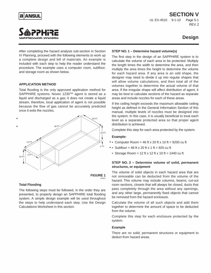
After completing the hazard analysis sub-section in SectionIV Planning, proceed with the following elements to work upa complete design and bill of materials. An example isincluded with each step to help the reader understand theprocedure. The example uses a computer room, subfloor,and storage room as shown below.
APPLICATION METHOD
Total flooding is the only approved application method forSAPPHIRE systems. Novec 1230™ agent is stored as aliquid and discharged as a gas; it does not create a liquidstream, therefore, local application of agent is not possiblebecause the flow of gas cannot be accurately predictedonce it exits the nozzles.
FIGURE 1006891
Total Flooding
The following steps must be followed, in the order they arepresented, to properly design an SAPPHIRE total floodingsystem. A simple design example will be used throughoutthe steps to help understand each step. Use the DesignCalculations Worksheet in this section.
STEP NO. 1 – Determine hazard volume(s)
The first step in the design of an SAPPHIRE system is tocalculate the volume of each area to be protected. Multiplythe length times the width to determine the area, and thenmultiply the area times the height to determine the volumefor each hazard area. If any area is an odd shape, thedesigner may need to divide it up into regular shapes thatwill allow volume calculations, and then total all of thevolumes together to determine the actual volume of thatarea. If the irregular shape will affect distribution of agent, itmay be best to calculate sections of the hazard as separateareas and include nozzles for each of these areas.
If the ceiling height exceeds the maximum allowable ceilingheight as defined in the General Information Section of thismanual, multiple levels of nozzles must be designed intothe system. In this case, it is usually beneficial to treat eachlevel as a separate protected area so that proper agentdistribution is achieved.
Complete this step for each area protected by the system.
Example:
• Computer Room = 46 ft x 20 ft x 10 ft = 9200 cu ft
• Subfloor = 46 ft x 20 ft x 1 ft = 920 cu ft
• Storage Room = 12 ft x 12 ft x 10 ft = 1440 cu ft
STEP NO. 2 – Determine volume of solid, permanentstructures, or equipment
The volume of solid objects in each hazard area that arenot removable can be deducted from the volume of thehazard. This volume may include columns, beams, cut-outroom sections, closets that will always be closed, ducts thatpass completely through the area without any openings,and any other large, permanently fixed objects that cannotbe removed from the hazard enclosure.
Calculate the volume of all such objects and add themtogether to determine the amount of space to be deductedfrom the volume.
Complete this step for each enclosure protected by thesystem.
Example
There are no solid, permanent structures or equipment todeduct from hazard areas.
SECTION VUL EX-4510 9-1-10 Page 5-1
REV. 2
Design
10 FT.
10 FT.
12 FT.
20 FT.
46 FT.
1 FT.
12 FT.
SECTION VUL EX-4510 3-1-07 Page 5-2REV. 2
Design
APPLICATION METHOD (Continued)
Total Flooding (Continued)
STEP NO. 3 – Calculate Reduced VolumeSubtract the volume of solid, permanent objects (Step No.2) from each of the hazard’s volumes (Step No. 1). Theresult is considered to be the Reduced Volume for theenclosure.
Volume – Solid Object Volume = Reduced Volume
Complete this step for each area protected by the system.
ExampleThere are no solid, permanent structures or equipment todeduct from hazard areas.
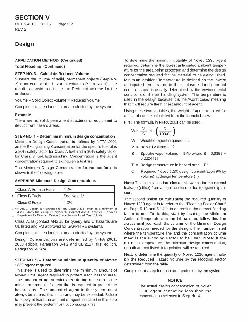
STEP NO. 4 – Determine minimum design concentrationMinimum Design Concentration is defined by NFPA 2001as the Extinguishing Concentration for the specific fuel plusa 20% safety factor for Class A fuel and a 30% safety factorfor Class B fuel. Extinguishing Concentration is the agentconcentration required to extinguish a test fire.
The Minimum Design Concentration for various fuels isshown in the following table:
SAPPHIRE Minimum Design Concentrations
* NOTE 1: Design concentration for any Class B fuel must be a minimum of4.2%. Many fuels require higher %. Contact Ansul Technical ServicesDepartment for Minimum Design Concentrations for all Class B fuels.
Class A, B (contact ANSUL for types), and C hazards areUL listed and FM approved for SAPPHIRE systems.
Complete this step for each area protected by the system.
Design Concentrations are determined by NFPA 2001,2000 edition, Paragraph 3-4.2 and UL-2127, first edition,Paragraph 59.2(b).
STEP NO. 5 – Determine minimum quantity of Novec1230 agent requiredThis step is used to determine the minimum amount ofNovec 1230 agent required to protect each hazard area.The amount of agent calculated during this step is theminimum amount of agent that is required to protect thehazard area. The amount of agent in the system mustalways be at least this much and may be exceeded. Failureto supply at least the amount of agent indicated in this stepmay prevent the system from suppressing a fire.
To determine the minimum quantity of Novec 1230 agentrequired, determine the lowest anticipated ambient temper-ature for the area being protected and determine the designconcentration required for the material to be extinguished.Minimum Ambient Temperature is defined as the lowestanticipated temperature in the enclosure during normalconditions and is usually determined by the environmentalconditions or the air handling system. This temperature isused in the design because it is the “worst case,” meaningthat it will require the highest amount of agent.
Using these two variables, the weight of agent required fora hazard can be calculated from the formula below:
First: The formula in NFPA 2001 can be used.
W = V X ( C )___ ______ S 100-C
W = Weight of agent required – lb
V = Hazard volume – ft3
S = Specific vapor volume – ft3/lb where S = 0.9856 +0.002441T
T = Design temperature in hazard area – F°
C = Required Novec 1230 design concentration (% byvolume) at design temperature (T)
Note: This calculation includes an allowance for the normalleakage (efflux) from a “tight” enclosure due to agent expan-sion.
The second option for calculating the required quantity ofNovec 1230 agent is to refer to the “Flooding Factor Chart”on Page 5-13 and 5-14 in to determine the correct floodingfactor to use. To do this, start by locating the MinimumAmbient Temperature in the left column, follow this lineacross until you reach the column for the Minimum DesignConcentration needed for the design. The number listedwhere the temperature line and the concentration columnmeet is the Flooding Factor to be used. Note: If theminimum temperature, the minimum design concentration,or both are not listed, interpolation will be required.
Next, to determine the quantity of Novec 1230 agent, multi-ply the Reduced Hazard Volume by the Flooding Factordetermined from the table.
Complete this step for each area protected by the system.
NOTICEThe actual design concentration of Novec1230 agent cannot be less than theconcentration selected in Step No. 4.
Class A Surface Fuels 4.2%
Class B Fuels See Note 1*
Class C Fuels 4.2%
APPLICATION METHOD (Continued)
Total Flooding (Continued)
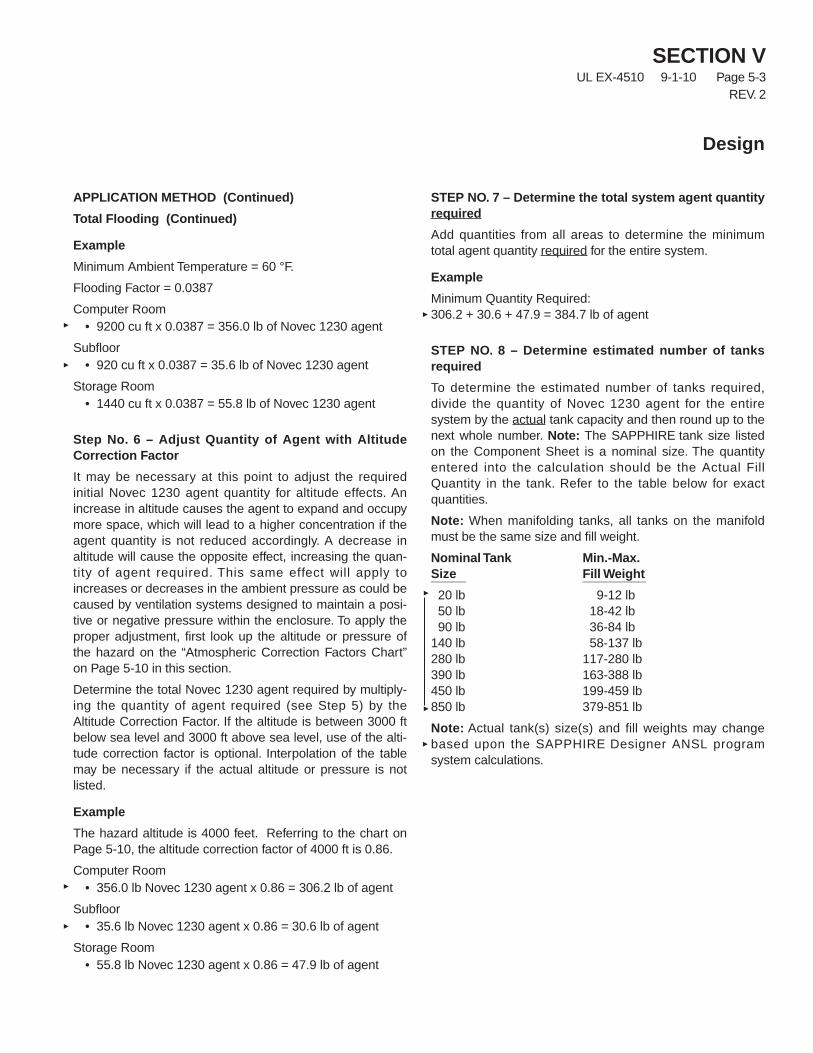
Example
Minimum Ambient Temperature = 60 °F.
Flooding Factor = 0.0387
Computer Room• 9200 cu ft x 0.0387 = 356.0 lb of Novec 1230 agent
Subfloor• 920 cu ft x 0.0387 = 35.6 lb of Novec 1230 agent
Storage Room• 1440 cu ft x 0.0387 = 55.8 lb of Novec 1230 agent
Step No. 6 – Adjust Quantity of Agent with AltitudeCorrection Factor
It may be necessary at this point to adjust the requiredinitial Novec 1230 agent quantity for altitude effects. Anincrease in altitude causes the agent to expand and occupymore space, which will lead to a higher concentration if theagent quantity is not reduced accordingly. A decrease inaltitude will cause the opposite effect, increasing the quan-tity of agent required. This same effect will apply toincreases or decreases in the ambient pressure as could becaused by ventilation systems designed to maintain a posi-tive or negative pressure within the enclosure. To apply theproper adjustment, first look up the altitude or pressure ofthe hazard on the “Atmospheric Correction Factors Chart”on Page 5-10 in this section.
Determine the total Novec 1230 agent required by multiply-ing the quantity of agent required (see Step 5) by theAltitude Correction Factor. If the altitude is between 3000 ftbelow sea level and 3000 ft above sea level, use of the alti-tude correction factor is optional. Interpolation of the tablemay be necessary if the actual altitude or pressure is notlisted.
Example
The hazard altitude is 4000 feet. Referring to the chart onPage 5-10, the altitude correction factor of 4000 ft is 0.86.
Computer Room• 356.0 lb Novec 1230 agent x 0.86 = 306.2 lb of agent
Subfloor• 35.6 lb Novec 1230 agent x 0.86 = 30.6 lb of agent
Storage Room• 55.8 lb Novec 1230 agent x 0.86 = 47.9 lb of agent
STEP NO. 7 – Determine the total system agent quantityrequired
Add quantities from all areas to determine the minimumtotal agent quantity required for the entire system.
Example
Minimum Quantity Required:306.2 + 30.6 + 47.9 = 384.7 lb of agent
STEP NO. 8 – Determine estimated number of tanksrequired
To determine the estimated number of tanks required,divide the quantity of Novec 1230 agent for the entiresystem by the actual tank capacity and then round up to thenext whole number. Note: The SAPPHIRE tank size listedon the Component Sheet is a nominal size. The quantityentered into the calculation should be the Actual FillQuantity in the tank. Refer to the table below for exactquantities.
Note: When manifolding tanks, all tanks on the manifoldmust be the same size and fill weight.
Nominal Tank Min.-Max.Size Fill Weight_____ _________20 lb 9-12 lb50 lb 18-42 lb90 lb 36-84 lb
140 lb 58-137 lb280 lb 117-280 lb390 lb 163-388 lb450 lb 199-459 lb850 lb 379-851 lb
Note: Actual tank(s) size(s) and fill weights may changebased upon the SAPPHIRE Designer ANSL programsystem calculations.
SECTION VUL EX-4510 9-1-10 Page 5-3
REV. 2
Design
SECTION VUL EX-4510 9-1-10 Page 5-4REV. 2
Design
APPLICATION METHOD (Continued)
Total Flooding (Continued)
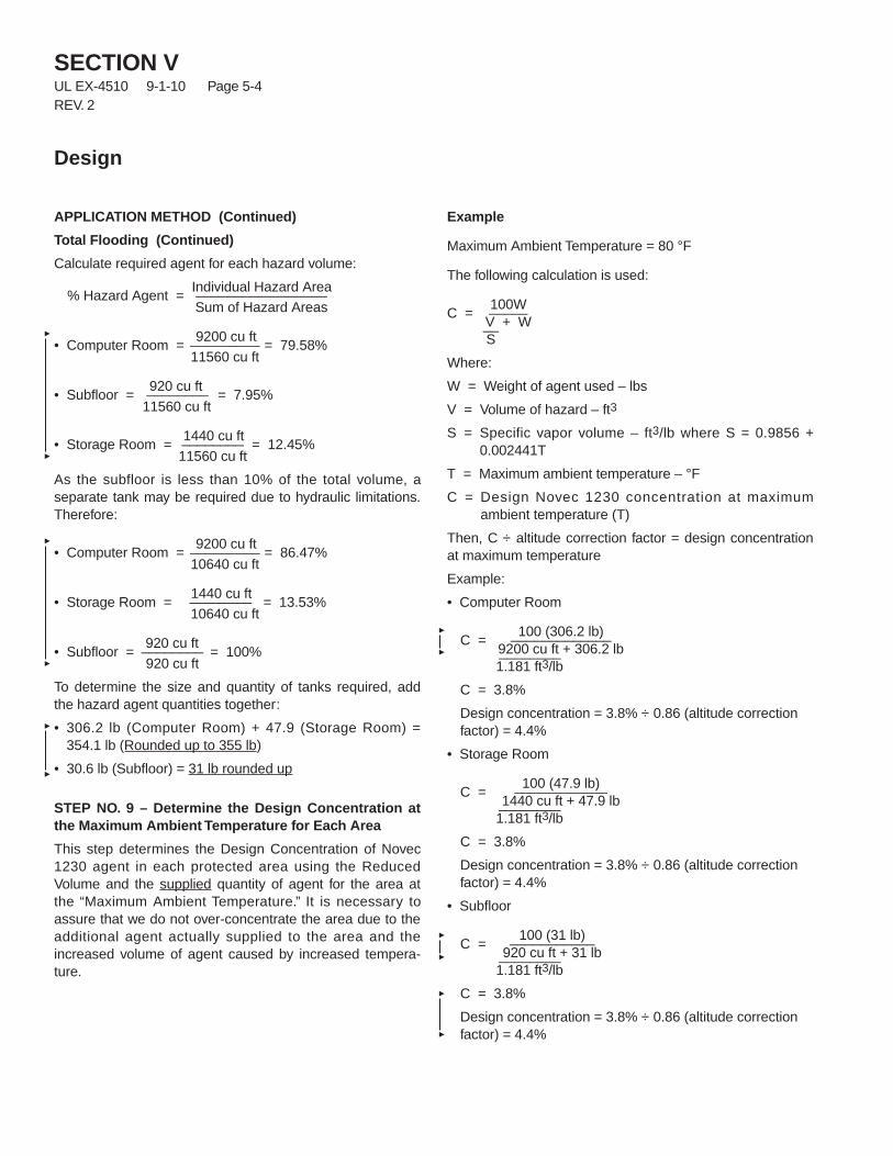
Calculate required agent for each hazard volume:
% Hazard Agent =Individual Hazard Area_________________Sum of Hazard Areas
• Computer Room =9200 cu ft
= 79.58%_________11560 cu ft
• Subfloor =920 cu ft
= 7.95%________11560 cu ft
• Storage Room =1440 cu ft
= 12.45%________11560 cu ft
As the subfloor is less than 10% of the total volume, aseparate tank may be required due to hydraulic limitations.Therefore:
• Computer Room =9200 cu ft
= 86.47%_________10640 cu ft
• Storage Room =1440 cu ft
= 13.53%________10640 cu ft
• Subfloor =920 cu ft
= 100%________ 920 cu ft
To determine the size and quantity of tanks required, addthe hazard agent quantities together:
• 306.2 lb (Computer Room) + 47.9 (Storage Room) =354.1 lb (Rounded up to 355 lb)
• 30.6 lb (Subfloor) = 31 lb rounded up
STEP NO. 9 – Determine the Design Concentration atthe Maximum Ambient Temperature for Each Area
This step determines the Design Concentration of Novec1230 agent in each protected area using the ReducedVolume and the supplied quantity of agent for the area atthe “Maximum Ambient Temperature.” It is necessary toassure that we do not over-concentrate the area due to theadditional agent actually supplied to the area and theincreased volume of agent caused by increased tempera-ture.
Example
Maximum Ambient Temperature = 80 °F
The following calculation is used:
C =100W_____
V + W__S
Where:
W = Weight of agent used – lbs
V = Volume of hazard – ft3
S = Specific vapor volume – ft3/lb where S = 0.9856 +0.002441T
T = Maximum ambient temperature – °F
C = Design Novec 1230 concentration at maximumambient temperature (T)
Then, C ÷ altitude correction factor = design concentrationat maximum temperature
Example:
• Computer Room
C =100 (306.2 lb)_____________
9200 cu ft + 306.2 lb________1.181 ft3/lb
C = 3.8%
Design concentration = 3.8% ÷ 0.86 (altitude correctionfactor) = 4.4%
• Storage Room
C =100 (47.9 lb)____________
1440 cu ft + 47.9 lb________1.181 ft3/lb
C = 3.8%
Design concentration = 3.8% ÷ 0.86 (altitude correctionfactor) = 4.4%
• Subfloor
C =100 (31 lb)___________
920 cu ft + 31 lb________1.181 ft3/lb
C = 3.8%
Design concentration = 3.8% ÷ 0.86 (altitude correctionfactor) = 4.4%
APPLICATION METHOD (Continued)Total Flooding (Continued)
STEP NO. 10 – Verify that the actual Novec 1230 agentconcentration is within the design concentration rangeof 4.2% to 10%This step is used to verify that the “worst case” designconcentration will not exceed limits for fire suppression onthe low end and life safety on the high end..
Note: Normally occupied space is defined as “one that isintended for occupancy” by NFPA 2001. The appendix ofNFPA 2001 states “spaces occasionally visited by person-nel, such as transformer bays, switch-houses, pump rooms,vaults, engine test stands, cable trays, tunnels, microwaverelay stations, flammable liquid storage areas, enclosedenergy systems, etc., are examples of areas considerednot normally occupied.”
Refer to NFPA 2001, Paragraph 1-6.1.3, for detailed expo-sure conditions.
Complete this step for each area protected by the system.
Example4.4% and 4.5% are between 4.2% and 10%, therefore thesystem design is acceptable.
STEP NO. 11 – Determine the Design Concentration atNormal Ambient Temperature
Complete the same procedure as done in Step No. 9 usingthe Normal Ambient Temperature instead of the MaximumAmbient Temperature.
Complete this step for each area protected by the system.
ExampleNormal Ambient Temperature = 70 °F.
• Computer Room
C =100 (306.2 lb)_____________
9200 cu ft + 306.2 lb________1.157 ft3/lb
C = 3.7%
Design concentration = 3.7% ÷ 0.86 (altitude correctionfactor) = 4.3%
• Storage Room
C =100 (47.9 lb)____________
1440 cu ft + 47.9 lb________1.157 ft3/lb
C = 3.7%
Design concentration = 3.7% ÷ 0.86 (altitude correctionfactor) = 4.3%
• Subfloor
C =100 (31 lb)___________
920 cu ft + 31 lb________1.157 ft3/lb
C = 3.8%
Design concentration = 3.8% ÷ 0.86 (altitude correctionfactor) = 4.4%
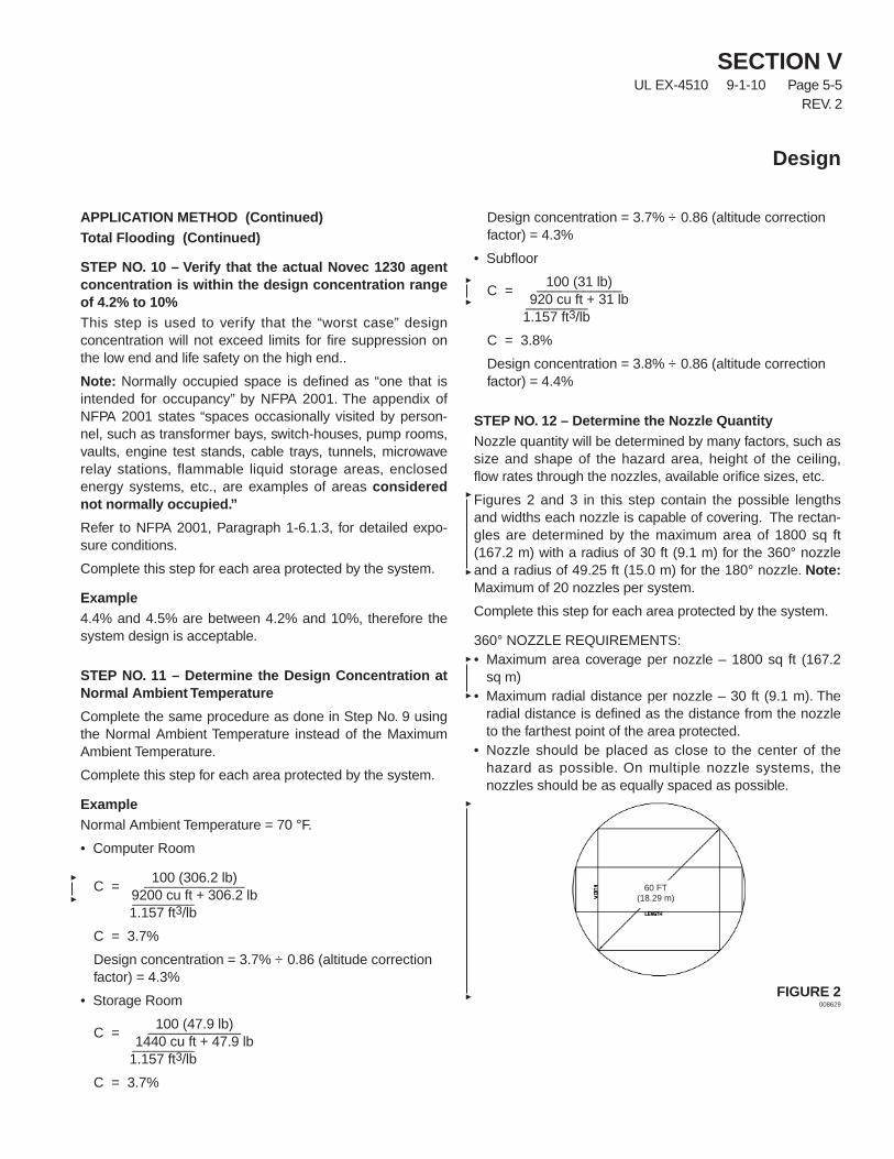
STEP NO. 12 – Determine the Nozzle QuantityNozzle quantity will be determined by many factors, such assize and shape of the hazard area, height of the ceiling,flow rates through the nozzles, available orifice sizes, etc.
Figures 2 and 3 in this step contain the possible lengthsand widths each nozzle is capable of covering. The rectan-gles are determined by the maximum area of 1800 sq ft(167.2 m) with a radius of 30 ft (9.1 m) for the 360° nozzleand a radius of 49.25 ft (15.0 m) for the 180° nozzle. Note:Maximum of 20 nozzles per system.
Complete this step for each area protected by the system.
360° NOZZLE REQUIREMENTS:• Maximum area coverage per nozzle – 1800 sq ft (167.2
sq m)• Maximum radial distance per nozzle – 30 ft (9.1 m). The
radial distance is defined as the distance from the nozzleto the farthest point of the area protected.
• Nozzle should be placed as close to the center of thehazard as possible. On multiple nozzle systems, thenozzles should be as equally spaced as possible.
FIGURE 2008629
SECTION VUL EX-4510 9-1-10 Page 5-5
REV. 2
Design
60 FT(18.29 m)
SECTION VUL EX-4510 9-1-10 Page 5-6
REV. 1
Design
APPLICATION METHOD (Continued)
Total Flooding (Continued)
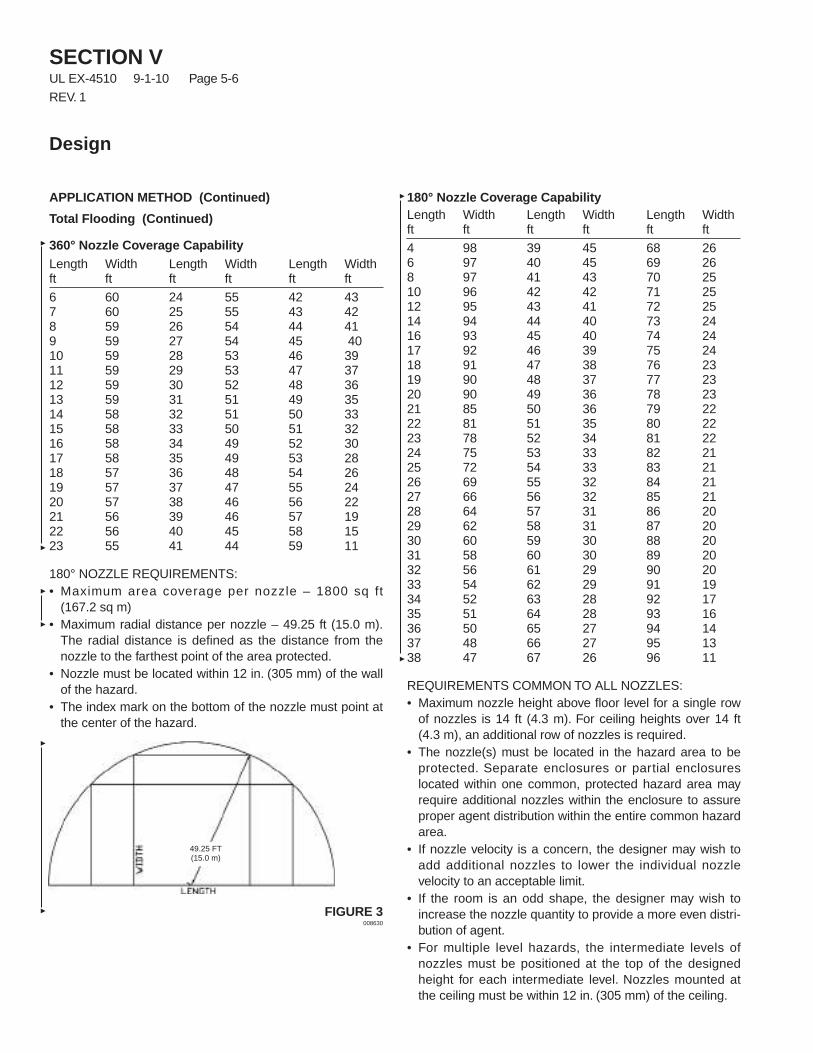
360° Nozzle Coverage CapabilityLength Width Length Width Length Widthft ft ft ft ft ft
6 60 24 55 42 437 60 25 55 43 428 59 26 54 44 419 59 27 54 45 4010 59 28 53 46 3911 59 29 53 47 3712 59 30 52 48 3613 59 31 51 49 3514 58 32 51 50 3315 58 33 50 51 3216 58 34 49 52 3017 58 35 49 53 2818 57 36 48 54 2619 57 37 47 55 2420 57 38 46 56 2221 56 39 46 57 1922 56 40 45 58 1523 55 41 44 59 11
180° NOZZLE REQUIREMENTS:• Maximum area coverage per nozzle – 1800 sq ft
(167.2 sq m)• Maximum radial distance per nozzle – 49.25 ft (15.0 m).
The radial distance is defined as the distance from thenozzle to the farthest point of the area protected.
• Nozzle must be located within 12 in. (305 mm) of the wallof the hazard.
• The index mark on the bottom of the nozzle must point atthe center of the hazard.
FIGURE 3008630
180° Nozzle Coverage CapabilityLength Width Length Width Length Widthft ft ft ft ft ft
4 98 39 45 68 266 97 40 45 69 268 97 41 43 70 2510 96 42 42 71 2512 95 43 41 72 2514 94 44 40 73 2416 93 45 40 74 2417 92 46 39 75 2418 91 47 38 76 2319 90 48 37 77 2320 90 49 36 78 2321 85 50 36 79 2222 81 51 35 80 2223 78 52 34 81 2224 75 53 33 82 2125 72 54 33 83 2126 69 55 32 84 2127 66 56 32 85 2128 64 57 31 86 2029 62 58 31 87 2030 60 59 30 88 2031 58 60 30 89 2032 56 61 29 90 2033 54 62 29 91 1934 52 63 28 92 1735 51 64 28 93 1636 50 65 27 94 1437 48 66 27 95 1338 47 67 26 96 11
REQUIREMENTS COMMON TO ALL NOZZLES:• Maximum nozzle height above floor level for a single row
of nozzles is 14 ft (4.3 m). For ceiling heights over 14 ft(4.3 m), an additional row of nozzles is required.
• The nozzle(s) must be located in the hazard area to beprotected. Separate enclosures or partial enclosureslocated within one common, protected hazard area mayrequire additional nozzles within the enclosure to assureproper agent distribution within the entire common hazardarea.
• If nozzle velocity is a concern, the designer may wish toadd additional nozzles to lower the individual nozzlevelocity to an acceptable limit.
• If the room is an odd shape, the designer may wish toincrease the nozzle quantity to provide a more even distri-bution of agent.
• For multiple level hazards, the intermediate levels ofnozzles must be positioned at the top of the designedheight for each intermediate level. Nozzles mounted atthe ceiling must be within 12 in. (305 mm) of the ceiling.
49.25 FT(15.0 m)
APPLICATION METHOD (Continued)
Total Flooding (Continued)
ExampleComputer RoomThe computer room is 46 ft x 20 ft. Therefore, using the360° chart, this can be covered using the 46 ft x 38.52 ftconfiguration:• 46 ft Length / 46 = 1.00 = 1 nozzle• 20 ft Width / 38.52 = 0.52 = 1 nozzle• 1 nozzle x 1 nozzle = 1 nozzle required for computer room
Storage RoomThe storage room is 12 ft x 12 ft. Therefore, using the 360°chart, this can be covered using the 12 ft x 58.78 ft configu-ration:• 12 ft Length / 12 = 1.00 = 1 nozzle• 12 ft Width / 58.78 = 0.20 = 1 nozzle• 1 nozzle x 1 nozzle = 1 nozzle required for storage room
SubfloorThe subfloor is 33 ft x 15 ft. Therefore, using the 360° chart,this can be covered using the 33 ft x 50.10 ft configuration:• 33 ft Length / 33 = 1.00 = 1 nozzle• 15 ft Width / 50.10 = 0.30 = 1 nozzle• 1 nozzle x 1 nozzle = 1 nozzle required for subfloor
STEP NO. 13 – Estimate Agent Flow Rate for Each Area
This step estimates the total flow rate into each protectedspace to allow the designer to estimate nozzle sizes forquotation purposes. Note: This is an estimate only. It is thedesigner’s responsibility to assess the correctness of thisestimate. If the flow rate approaches the top end of theallowable flow rate for a given size pipe, it may be in theDesigner’s best interest to increase the pipe size.
Complete this step for each area protected by the system.
Example
Computer Room• 306.2 lb ÷ 10 seconds = 30.62 lb/sec
Storage Room• 47.9 lb ÷ 10 seconds = 4.8 lb/sec
Subfloor• 31 lb ÷ 10 seconds = 3.1 lb/sec
STEP NO. 14 – Estimate the Nozzle Flow Rates
If all of the nozzles within the hazard area will have thesame flow rate, divide the Estimated Flow Rate for the Area(Step No. 13) by the nozzle quantity (Step No. 12).
If all of the nozzles within the hazard area will not have thesame flow rate, perform a percentage calculation using thevolume protected by each nozzle divided by the totalvolume for the area and then multiply the Flow Rate for theArea (Step No. 13) by the volume percent calculated previ-ously to determine the flow rate for that nozzle. Completethis procedure for each nozzle in the system.
If the design includes multiple levels of nozzles, rememberto include all nozzles on all levels in this step.
Complete this step for each area protected by the system.
Example
Computer Room• 30.62 lb/sec ÷ 1 nozzle = 30.62 lb/sec per nozzle
Storage Room• 4.8 lb/sec ÷ 1 nozzle = 4.8 lb/sec
Subfloor• 3.1 lb/sec ÷ 1 nozzle = 3.1 lb/sec per nozzle
STEP NO. 15 – Determine the Nozzle Locations and LayOut the Interconnecting Piping
Using a plan view drawing of the protected areas, locateeach nozzle and the tanks. Note: Nozzles should belocated at the top of the hazard area, aimed up or down.(Nozzles in subfloor can also be aimed upward or down-ward.) Connect the nozzles with piping following the pipingguidelines listed in the General Information Section and theInstallation Section. After all of the nozzles are connected,lay out the piping to the tanks and lay out the manifold.
STEP 16 – Complete an Isometric Sketch of the PipingLayout
Create an isometric sketch of the piping for use in inputtingthe information in the SAPPHIRE Designer ANSL program.
Piping Node Points
A node point defines the star t or end of a branch(segment) in the pipe system. A branch can consist of a runof pipe or another object such as a flex hose or check valve.Each node point is indicated on the isometric screen of thesoftware by a circle.
SECTION VUL EX-4510 9-1-10 Page 5-7
REV. 2
Design
SECTION VUL EX-4510 9-1-10 Page 5-8REV. 2
Design
APPLICATION METHOD (Continued)
Total Flooding (Continued)
STEP 16 – Complete an Isometric Sketch of the PipingLayout (Continued)Segment 1 (Node 0 to 1) always represents the cylinder.This segment can never be changed. The pipe length is thesiphon tube/valve length (which is also the elevation changefor the vertical cylinder) and the total equivalent length isthe measured equivalent length of the siphon tube/valveassembly. The designer program will number the rest of thepipe segments, as they are input.
NozzlesNozzles are indicated with the number of the enclosure andthe number of the nozzle in that enclosure (i.e., E1N1 –E1N2). The designer program assigns the nozzle indicators.Sequential placement is not required; however, it is recom-mended that the designer use some sort of numberingsystem to prevent confusion.
STEP 17 – Estimate Pipe Size for All Areas (Optional)To complete this step, start by labeling all nozzle flow rates.Then, working backwards from the nozzles, determine theflow rate for each section of pipe using the flow rate limita-tions and design/calculation limitations.
The flow calculation program will estimate pipe sizes auto-matically; therefore this step is optional. The designer maywish to use the pipe size estimation charts to estimate thenozzle pipe sizes for quotation purposes. Note: This is anestimate only. It is the designer’s responsibility to assessthe correctness of this estimate. If the flow rate approachesthe top end of the allowable flow rate for a given size, it maybe in the designer’s best interest to increase the pipe size.
Example
Computer Room• 30.62 lb/sec per nozzle = 2 in.
Storage Room• 4.8 lb/sec = 1 in.
Subfloor• 3.1 lb/sec = 3/4 in.
STEP NO. 18 – Perform Flow CalculationsWith the information developed in Steps No. 15 and 16, runthe computer program to determine the final pipe sizes andnozzle orifice sizes. The SAPPHIRE Designer Program isthe only calculation method to be used with ANSULEngineered Systems.
STEP NO. 19 – Verify Actual System Performance
Once a flow calculation has been completed and theDesign Worksheet has been revised (optional), it is impor-tant that the designer review all results to verify systemperformance. The SAPPHIRE Flow program will flag mosterrors and prevent a completed flow calculation until theyhave been corrected. However, this does not guarantee thatthe systems performance will match what the designerexpects. Careful review is an important step in the design ofany Fire Protection system, which must be completedbefore final approval of the system.
Review the revised worksheet to verify that:
1. The agent concentration at maximum temperature iswithin acceptable limits (4.2% to 10% for occupiedspaces).
2. The agent quantity is above the amount required in theActual Quantity box (See Step No. 7).
STEP NO. 20 – Complete Layout of the System
At this point, all final details of the system can be finalized.
STEP NO. 21 – Create Estimated Bill of Materials
Create a list of all materials necessary to install the system.
Note : Actual tank(s) size(s) and fill weights may changebased upon the SAPPHIRE Designer ANSL programsystem calculations.
STEP NO. 22 – Create Installation Drawings
The final step in the design of an SAPPHIRE system iscompletion of installation drawings for submittal to theappropriate authority and the customer. These drawingsshould include all details necessary for installation of thissystem.
SAMPLE APPLICATIONS
Refer to Section X (Typical Applications) for an example ofa typical application. By reviewing this example, it may helpanswer some questions concerning the total designprocess.
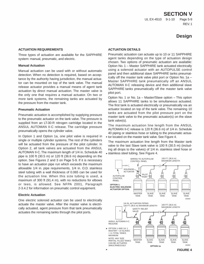
ACTUATION REQUIREMENTS
Three types of actuation are available for the SAPPHIREsystem: manual, pneumatic, and electric.
Manual Actuation
Manual actuation can be used with or without automaticdetection. When no detection is required, based on accep-tance by the authority having jurisdiction, the manual actua-tor can be mounted on top of the tank valve. The manualrelease actuator provides a manual means of agent tankactuation by direct manual actuation. The master valve isthe only one that requires a manual actuator. On two ormore tank systems, the remaining tanks are actuated bythe pressure from the master tank.
Pneumatic Actuation
Pneumatic actuation is accomplished by supplying pressureto the pneumatic actuator on the tank valve. The pressure issupplied from an LT-30-R nitrogen cartridge located in theANSUL AUTOMAN II-C release. The cartridge pressurepneumatically opens the cylinder valve.
In Option 1 and Option 1a, one pilot valve is required insingle or multiple cylinder systems. The rest of the cylinderswill be actuated from the pressure of the pilot cylinder. InOption 2, all tank valves are actuated from the ANSULAUTOMAN II-C. The maximum length of 1/4 in. Schedule 40pipe is 100 ft (30.5 m) or 120 ft (36.6 m) depending on theoption. See Figures 2 and 3 on Page 5-9. If it is necessaryto have an actuation pipe run which exceeds the maximumallowable 1/4 in. pipe requirements, 1/4 in. O.D. stainlesssteel tubing with a wall thickness of 0.065 can be used forthe actuation line. When this size tubing is used, amaximum of 300 ft (91.4 m), with no reductions for elbowsor tees, is allowed. See NFPA 2001, Paragraph2-3.4.2 for information on pneumatic control equipment.
Electric Actuation
One electric solenoid actuator can be used to electricallyactuate the master valve. After the master valve is electri-cally actuated, agent pressure from that tank pneumaticallyactuates the remaining tanks through the pilot ports.
ACTUATION DETAILS
Pneumatic actuation can actuate up to 10 or 11 SAPPHIREagent tanks depending on the type of actuation designchosen. Two options of pneumatic actuation are available:Option No. 1 – Master SAPPHIRE tank actuated electricallyusing a solenoid actuator with an AUTOPULSE controlpanel and then additional slave SAPPHIRE tanks pneumat-ically off the master tank valve pilot port or Option No. 1a –Master SAPPHIRE tank pneumatically off an ANSULAUTOMAN II-C releasing device and then additional slaveSAPPHIRE tanks pneumatically off the master tank valvepilot port.
Option No. 1 or No. 1a – Master/Slave option – This optionallows 11 SAPPHIRE tanks to be simultaneous actuated.The first tank is actuated electrically or pneumatically via anactuator located on top of the tank valve. The remaining 10tanks are actuated from the pilot pressure port on themaster tank valve to the pneumatic actuator(s) on the slavetank valve(s).
The maximum actuation line length from the ANSULAUTOMAN II-C release is 120 ft (36.6 m) of 1/4 in. Schedule40 piping or stainless hose or tubing to the pneumatic actua-tor located on the master tank valve. See Figure 4.
The maximum actuation line length from the Master tankvalve to the last Slave tank valve is 100 ft (30.5 m) (includ-ing all drops to the valves) of 1/4 in. stainless steel hose orstainless steel tubing. See Figure 4.
FIGURE 4
SECTION VUL EX-4510 9-1-10 Page 5-9
REV. 1
Design
MASTERTANK
SLAVETANK
SLAVETANK
SLAVETANK
SLAVETANK
OPTION 1 AND 1A: 1MASTER + 10 SLAVES= 11 TOTAL TANKSMAXIMUM
NOTE: ANY SIZEPARTIAL FILLED TANKSCAN BE ACTUATEDSIMULTANEOUSLY
SAFETY RELIEFVALVE
1/4 IN. ACTUATION PIPING120 FT. (36.6 m) MAXIMUM LENGTH 100 FT. (36.6 m)
MAXIMUM LENGTH
ANSUL AUTOMAN II-CRELEASE
OPTION 1a 006892
MASTERTANK
SLAVETANK
SLAVETANK
SLAVETANK
SLAVETANK
SOLENOIDACTUATOR
PILOTPORT
WIRING TO AUTOPULSECONTROL PANEL
100 FT. (36.6 m)MAXIMUM LENGTH
AUTOPULSECONTROLPANEL
OPTION 1:ELECTRIC SOLENOIDACTUATOR OPTION
006899
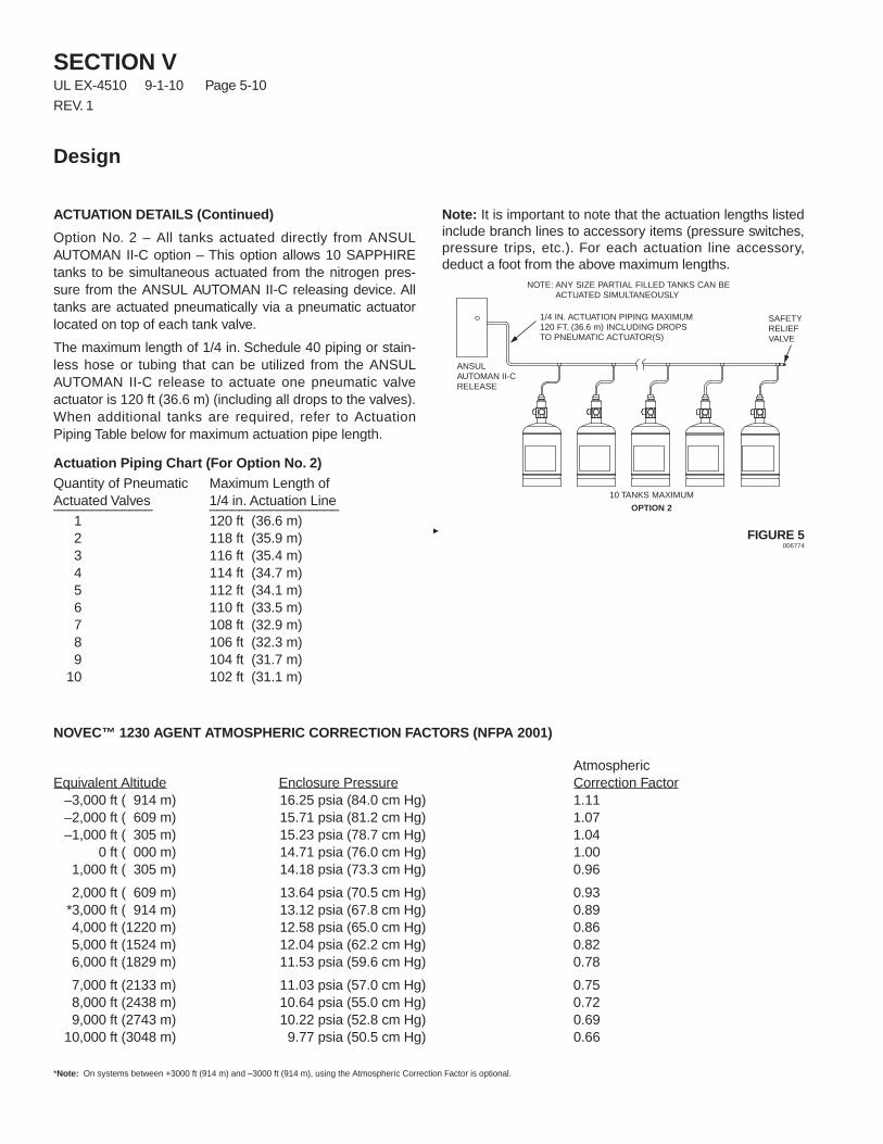
SECTION VUL EX-4510 9-1-10 Page 5-10
REV. 1
Design
ACTUATION DETAILS (Continued)
Option No. 2 – All tanks actuated directly from ANSULAUTOMAN II-C option – This option allows 10 SAPPHIREtanks to be simultaneous actuated from the nitrogen pres-sure from the ANSUL AUTOMAN II-C releasing device. Alltanks are actuated pneumatically via a pneumatic actuatorlocated on top of each tank valve.
The maximum length of 1/4 in. Schedule 40 piping or stain-less hose or tubing that can be utilized from the ANSULAUTOMAN II-C release to actuate one pneumatic valveactuator is 120 ft (36.6 m) (including all drops to the valves).When additional tanks are required, refer to ActuationPiping Table below for maximum actuation pipe length.
Actuation Piping Chart (For Option No. 2)Quantity of Pneumatic Maximum Length ofActuated Valves 1/4 in. Actuation Line_____________ _________________
1 120 ft (36.6 m)2 118 ft (35.9 m)3 116 ft (35.4 m)4 114 ft (34.7 m)5 112 ft (34.1 m)6 110 ft (33.5 m)7 108 ft (32.9 m)8 106 ft (32.3 m)9 104 ft (31.7 m)
10 102 ft (31.1 m)
Note: It is important to note that the actuation lengths listedinclude branch lines to accessory items (pressure switches,pressure trips, etc.). For each actuation line accessory,deduct a foot from the above maximum lengths.
FIGURE 5006774
10 TANKS MAXIMUM
OPTION 2
SAFETYRELIEFVALVE
1/4 IN. ACTUATION PIPING MAXIMUM120 FT. (36.6 m) INCLUDING DROPSTO PNEUMATIC ACTUATOR(S)
ANSULAUTOMAN II-CRELEASE
NOTE: ANY SIZE PARTIAL FILLED TANKS CAN BEACTUATED SIMULTANEOUSLY
NOVEC™ 1230 AGENT ATMOSPHERIC CORRECTION FACTORS (NFPA 2001)
AtmosphericEquivalent Altitude Enclosure Pressure Correction Factor
–3,000 ft ( 914 m) 16.25 psia (84.0 cm Hg) 1.11–2,000 ft ( 609 m) 15.71 psia (81.2 cm Hg) 1.07–1,000 ft ( 305 m) 15.23 psia (78.7 cm Hg) 1.04
0 ft ( 000 m) 14.71 psia (76.0 cm Hg) 1.001,000 ft ( 305 m) 14.18 psia (73.3 cm Hg) 0.96
2,000 ft ( 609 m) 13.64 psia (70.5 cm Hg) 0.93*3,000 ft ( 914 m) 13.12 psia (67.8 cm Hg) 0.894,000 ft (1220 m) 12.58 psia (65.0 cm Hg) 0.865,000 ft (1524 m) 12.04 psia (62.2 cm Hg) 0.826,000 ft (1829 m) 11.53 psia (59.6 cm Hg) 0.78
7,000 ft (2133 m) 11.03 psia (57.0 cm Hg) 0.758,000 ft (2438 m) 10.64 psia (55.0 cm Hg) 0.729,000 ft (2743 m) 10.22 psia (52.8 cm Hg) 0.69
10,000 ft (3048 m) 9.77 psia (50.5 cm Hg) 0.66
*Note: On systems between +3000 ft (914 m) and –3000 ft (914 m), using the Atmospheric Correction Factor is optional.
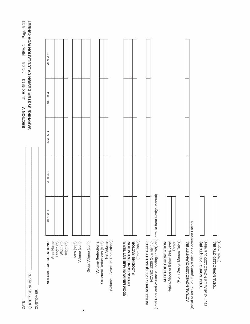
DAT
E:
____
____
____
____
____
____
____
____
____
____
____
____
____
____
____
____
____
____
____
__
QU
OT
E/J
OB
NU
MB
ER
:__
____
____
____
____
____
____
____
____
____
____
____
____
____
____
____
__
CU
STO
ME
R:
____
____
____
____
____
____
____
____
____
____
____
____
____
____
____
____
____
____
VO
LU
ME
CA
LC
UL
AT
ION
S:
AR
EA
1A
RE
A2
AR
EA
3A
RE
A4
AR
EA
5A
rea
Nam
e:Le
ngth
(ft)
:W
idth
(ft)
:H
eigh
t(ft)
:
Are
a(s
qft)
:V
olum
e(c
uft)
:
Gro
ssV
olum
e(c
uft)
:
Volu
me
Red
uct
ion
s:S
truc
tura
lRed
uctio
ns(c
uft)
:N
etV
olum
e:(V
olum
e–
Str
uctu
ralR
educ
tions
)
RO
OM
MIN
IMU
MA
MB
IEN
TT
EM
P.:
DE
SIG
NC
ON
CE
NT
RA
TIO
N:
FL
OO
DIN
GFA
CTO
R:
(Fro
mTa
ble)
INIT
IAL
NO
VE
C12
30Q
UA
NT
ITY
CA
LC
.:N
OV
EC
1230
Qua
ntity
(lb):
(Tot
alR
educ
edV
olum
ex
Flo
odin
gFa
ctor
)or
(For
mul
afr
omD
esig
nM
anua
l)
ALT
ITU
DE
CO
RR
EC
TIO
N:
Hei
ghtA
bove
orB
elow
Sea
Leve
l:Fa
ctor
:(F
rom
Des
ign
Man
ualT
able
)
AC
TU
AL
NO
VE
C12
30Q
UA
NT
ITY
(lb
):(I
nitia
lNO
VE
C12
30Q
uant
ityx
Alti
tude
Cor
rect
ion
Fact
or)
TOTA
LN
OV
EC
1230
QT
Y.(l
b):
(Sum
ofal
lAct
ualN
OV
EC
1230
quan
titie
s)
TOTA
LN
OV
EC
1230
QT
Y.(l
b):
(Fro
mP
age
1)
SE
CT
ION
VU
LE
X-4
510
4-1-
05R
EV.
1P
age
5-11
SA
PP
HIR
ES
YS
TE
MD
ES
IGN
CA
LC
UL
AT
ION
WO
RK
SH
EE
T
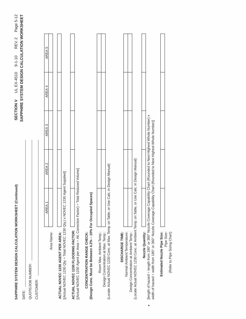
DAT
E:
____
____
____
____
____
____
____
____
____
____
____
____
____
____
____
____
____
____
____
__
QU
OT
E/J
OB
NU
MB
ER
:__
____
____
____
____
____
____
____
____
____
____
____
____
____
____
____
__
CU
STO
ME
R:
____
____
____
____
____
____
____
____
____
____
____
____
____
____
____
____
____
____
AR
EA
1A
RE
A2
AR
EA
3A
RE
A4
AR
EA
5A
rea
Nam
e:
AC
TU
AL
NO
VE
C12
30A
GE
NT
PE
RA
RE
A:
[(A
ctua
lNO
VE
C12
30Q
ty.÷
Tota
lNO
VE
C12
30Q
ty.)
xN
OV
EC
1230
Age
ntS
uppl
ied]
AC
TU
AL
NO
VE
C12
30F
LO
OD
ING
FAC
TOR
:[(
Act
ualN
OV
EC
1230
Age
ntpe
rA
rea
÷A
lt.C
orre
ctio
nFa
ctor
)÷
Tota
lRed
uced
Vol
ume]
CO
NC
EN
TR
AT
ION
RA
NG
EC
HE
CK
:(D
esig
nC
on
c.M
ust
be
Bet
wee
n4.
2%–
10%
Fo
rO
ccu
pie
dS
pac
es)
Roo
mM
ax.A
mbi
entT
emp.
:D
esig
nC
once
ntra
tion
atM
ax.T
emp.
:(L
ocat
eA
ctua
lNO
VE
C12
30C
onc.
atM
ax.T
emp.
onTa
ble,
orU
seC
alc.
inD
esig
nM
anua
l)
DIS
CH
AR
GE
TIM
E:
Nor
mal
Am
bien
tTem
pera
ture
:D
esig
nC
once
ntra
tion
atA
mbi
entT
emp.
:(L
ocat
eA
ctua
lNO
VE
C12
30C
onc.
atA
mbi
entT
emp.
onTa
ble,
orU
seC
alc.
inD
esig
nM
anua
l)
No
zzle
Qu
anti
ty:
[leng
thof
haza
rd÷
leng
thfr
om18
0°or
360°
Noz
zle
Cov
erag
eC
apab
ility
Cha
rt(R
ound
edto
Nex
tHig
hest
Who
leN
umbe
r)x
wid
thof
haza
rd÷
wid
thfr
om18
0°or
360°
Noz
zle
Cov
erag
eC
apab
ility
Cha
rt(R
ound
edto
Nex
tHig
hest
Who
leN
umbe
r)]
Est
imat
edN
ozz
leP
ipe
Siz
e:P
ipe
Siz
e:(R
efer
toP
ipe
Siz
ing
Cha
rt)
SA
PP
HIR
ES
YS
TE
MD
ES
IGN
CA
LC
UL
AT
ION
WO
RK
SH
EE
T(C
on
tin
ued
)S
EC
TIO
NV
UL
EX
-451
09-
1-10
RE
V.2
Pag
e5-
12
SA
PP
HIR
ES
YS
TE
MD
ES
IGN
CA
LC
UL
AT
ION
WO
RK
SH
EE
T
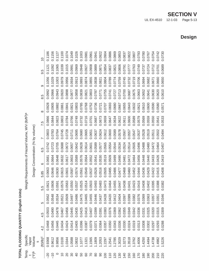
TOTA
LF
LO
OD
ING
QU
AN
TIT
Y(E
ng
lish
Un
its)
Tem
p.S
peci
ficW
eigh
tReq
uire
men
tsof
Haz
ard
Vol
ume,
W/V
(lb/ft
3 )a
tV
apor
(°F
)bV
olum
eD
esig
nC
once
ntra
tion
(%by
volu
me)
s
(ft3
/lb)c
4.2
4.5
55.
55.
856
6.5
77.
58
8.5
99.
510
–20
0.93
680.
0468
0.05
030.
0562
0.06
210.
0663
0.06
810.
0742
0.08
030.
0866
0.09
280.
0992
0.10
560.
1121
0.11
86
–10
0.96
120.
0456
0.04
900.
0548
0.06
060.
0646
0.06
640.
0723
0.07
830.
0844
0.09
050.
0966
0.10
290.
1092
0.11
56
00.
9856
0.04
450.
0478
0.05
340.
0591
0.06
300.
0648
0.07
050.
0764
0.08
230.
0882
0.09
430.
1003
0.10
650.
1127
101.
0100
0.04
340.
0467
0.05
210.
0576
0.06
150.
0632
0.06
880.
0745
0.08
030.
0861
0.09
200.
0979
0.10
390.
1100
201.
0344
0.04
240.
0456
0.05
090.
0563
0.06
010.
0617
0.06
720.
0728
0.07
840.
0841
0.08
980.
0956
0.10
150.
1074
301.
0588
0.04
140.
0445
0.04
970.
0550
0.05
870.
0603
0.06
570.
0711
0.07
660.
0821
0.08
770.
0934
0.09
910.
1049
401.
0832
0.04
050.
0435
0.04
860.
0537
0.05
740.
0589
0.06
420.
0695
0.07
490.
0803
0.08
580.
0913
0.09
690.
1026
501.
1077
0.03
960.
0425
0.04
750.
0525
0.05
610.
0576
0.06
280.
0680
0.07
320.
0785
0.08
390.
0893
0.09
480.
1003
601.
1321
0.03
870.
0416
0.04
650.
0514
0.05
490.
0564
0.06
140.
0665
0.07
160.
0768
0.08
210.
0874
0.09
270.
0981
701.
1565
0.03
790.
0407
0.04
550.
0503
0.05
370.
0552
0.06
010.
0651
0.07
010.
0752
0.08
030.
0855
0.09
080.
0961
801.
1809
0.03
710.
0399
0.04
460.
0493
0.05
260.
0541
0.05
890.
0637
0.06
870.
0736
0.07
870.
0838
0.08
890.
0941
901.
2053
0.03
640.
0391
0.04
370.
0483
0.05
160.
0530
0.05
770.
0624
0.06
730.
0721
0.07
710.
0821
0.08
710.
0922
100
1.22
970.
0357
0.03
830.
0428
0.04
730.
0505
0.05
190.
0565
0.06
120.
0659
0.07
070.
0755
0.08
040.
0854
0.09
04
110
1.25
410.
0350
0.03
760.
0420
0.04
640.
0495
0.05
090.
0554
0.06
000.
0647
0.06
930.
0741
0.07
890.
0837
0.08
86
120
1.27
850.
0343
0.03
690.
0412
0.04
550.
0486
0.04
990.
0544
0.05
890.
0634
0.06
800.
0727
0.07
740.
0821
0.08
69
130
1.30
290.
0336
0.03
620.
0404
0.04
470.
0477
0.04
900.
0534
0.05
780.
0622
0.06
670.
0713
0.07
590.
0806
0.08
53
140
1.32
730.
0330
0.03
550.
0397
0.04
380.
0468
0.04
810.
0524
0.05
670.
0611
0.06
550.
0700
0.07
450.
0791
0.08
37
150
1.35
180.
0324
0.03
490.
0389
0.04
310.
0460
0.04
720.
0514
0.05
570.
0600
0.06
430.
0687
0.07
320.
0777
0.08
22
160
1.37
620.
0319
0.03
420.
0382
0.04
230.
0452
0.04
640.
0505
0.05
470.
0589
0.06
320.
0675
0.07
190.
0763
0.08
07
170
1.40
060.
0313
0.03
360.
0376
0.04
160.
0444
0.04
560.
0496
0.05
370.
0579
0.06
210.
0663
0.07
060.
0749
0.07
93
180
1.42
500.
0308
0.03
310.
0369
0.04
080.
0436
0.04
480.
0488
0.05
280.
0569
0.06
100.
0652
0.06
940.
0737
0.07
80
190
1.44
940.
0302
0.03
250.
0363
0.04
020.
0429
0.04
400.
0480
0.05
190.
0559
0.06
000.
0641
0.06
820.
0724
0.07
67
200
1.47
380.
0297
0.03
200.
0357
0.03
950.
0422
0.04
330.
0472
0.05
110.
0550
0.05
900.
0630
0.06
710.
0712
0.07
54
210
1.49
820.
0293
0.03
150.
0351
0.03
880.
0415
0.04
260.
0464
0.05
020.
0541
0.05
800.
0620
0.06
600.
0701
0.07
42
220
1.52
260.
0288
0.03
090.
0346
0.03
820.
0408
0.04
190.
0457
0.04
940.
0533
0.05
710.
0610
0.06
500.
0689
0.07
30
SECTION VUL EX-4510 12-1-03 Page 5-13
Design
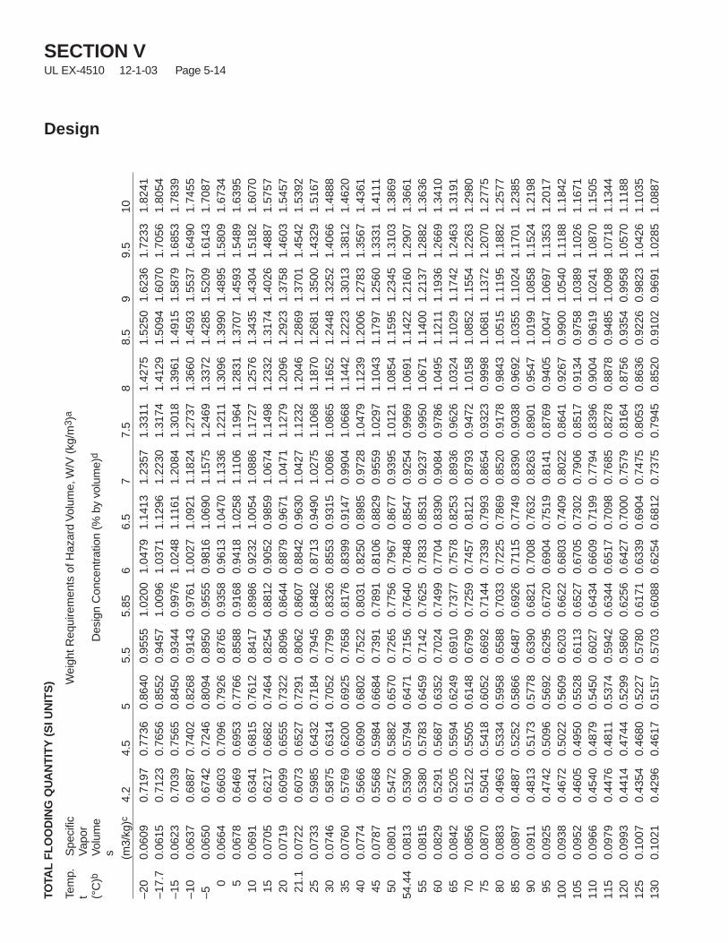
SECTION VUL EX-4510 12-1-03 Page 5-14
Design
TOTA
LF
LO
OD
ING
QU
AN
TIT
Y(S
IUN
ITS
)
Tem
p.S
peci
ficW
eigh
tReq
uire
men
tsof
Haz
ard
Vol
ume,
W/V
(kg/
m3 )
a
tV
apor
(°C
)bV
olum
eD
esig
nC
once
ntra
tion
(%by
volu
me)
d
s (m3/
kg)c
4.2
4.5
55.
55.
856
6.5
77.
58
8.5
99.
510
–20
0.06
090.
7197
0.77
360.
8640
0.95
551.
0200
1.04
791.
1413
1.23
571.
3311
1.42
751.
5250
1.62
361.
7233
1.82
41–1
7.7
0.06
150.
7123
0.76
560.
8552
0.94
571.
0096
1.03
711.
1296
1.22
301.
3174
1.41
291.
5094
1.60
701.
7056
1.80
54–1
50.
0623
0.70
390.
7565
0.84
500.
9344
0.99
761.
0248
1.11
611.
2084
1.30
181.
3961
1.49
151.
5879
1.68
531.
7839
–10
0.06
370.
6887
0.74
020.
8268
0.91
430.
9761
1.00
271.
0921
1.18
241.
2737
1.36
601.
4593
1.55
371.
6490
1.74
55–5
0.06
500.
6742
0.72
460.
8094
0.89
500.
9555
0.98
161.
0690
1.15
751.
2469
1.33
721.
4285
1.52
091.
6143
1.70
870
0.06
640.
6603
0.70
960.
7926
0.87
650.
9358
0.96
131.
0470
1.13
361.
2211
1.30
961.
3990
1.48
951.
5809
1.67
345
0.06
780.
6469
0.69
530.
7766
0.85
880.
9168
0.94
181.
0258
1.11
061.
1964
1.28
311.
3707
1.45
931.
5489
1.63
9510
0.06
910.
6341
0.68
150.
7612
0.84
170.
8986
0.92
321.
0054
1.08
861.
1727
1.25
761.
3435
1.43
041.
5182
1.60
7015
0.07
050.
6217
0.66
820.
7464
0.82
540.
8812
0.90
520.
9859
1.06
741.
1498
1.23
321.
3174
1.40
261.
4887
1.57
5720
0.07
190.
6099
0.65
550.
7322
0.80
960.
8644
0.88
790.
9671
1.04
711.
1279
1.20
961.
2923
1.37
581.
4603
1.54
5721
.10.
0722
0.60
730.
6527
0.72
910.
8062
0.86
070.
8842
0.96
301.
0427
1.12
321.
2046
1.28
691.
3701
1.45
421.
5392
250.
0733
0.59
850.
6432
0.71
840.
7945
0.84
820.
8713
0.94
901.
0275
1.10
681.
1870
1.26
811.
3500
1.43
291.
5167
300.
0746
0.58
750.
6314
0.70
520.
7799
0.83
260.
8553
0.93
151.
0086
1.08
651.
1652
1.24
481.
3252
1.40
661.
4888
350.
0760
0.57
690.
6200
0.69
250.
7658
0.81
760.
8399
0.91
470.
9904
1.06
681.
1442
1.22
231.
3013
1.38
121.
4620
400.
0774
0.56
660.
6090
0.68
020.
7522
0.80
310.
8250
0.89
850.
9728
1.04
791.
1239
1.20
061.
2783
1.35
671.
4361
450.
0787
0.55
680.
5984
0.66
840.
7391
0.78
910.
8106
0.88
290.
9559
1.02
971.
1043
1.17
971.
2560
1.33
311.
4111
500.
0801
0.54
720.
5882
0.65
700.
7265
0.77
560.
7967
0.86
770.
9395
1.01
211.
0854
1.15
951.
2345
1.31
031.
3869
54.4
40.
0813
0.53
900.
5794
0.64
710.
7156
0.76
400.
7848
0.85
470.
9254
0.99
691.
0691
1.14
221.
2160
1.29
071.
3661
550.
0815
0.53
800.
5783
0.64
590.
7142
0.76
250.
7833
0.85
310.
9237
0.99
501.
0671
1.14
001.
2137
1.28
821.
3636
600.
0829
0.52
910.
5687
0.63
520.
7024
0.74
990.
7704
0.83
900.
9084
0.97
861.
0495
1.12
111.
1936
1.26
691.
3410
650.
0842
0.52
050.
5594
0.62
490.
6910
0.73
770.
7578
0.82
530.
8936
0.96
261.
0324
1.10
291.
1742
1.24
631.
3191
700.
0856
0.51
220.
5505
0.61
480.
6799
0.72
590.
7457
0.81
210.
8793
0.94
721.
0158
1.08
521.
1554
1.22
631.
2980
750.
0870
0.50
410.
5418
0.60
520.
6692
0.71
440.
7339
0.79
930.
8654
0.93
230.
9998
1.06
811.
1372
1.20
701.
2775
800.
0883
0.49
630.
5334
0.59
580.
6588
0.70
330.
7225
0.78
690.
8520
0.91
780.
9843
1.05
151.
1195
1.18
821.
2577
850.
0897
0.48
870.
5252
0.58
660.
6487
0.69
260.
7115
0.77
490.
8390
0.90
380.
9692
1.03
551.
1024
1.17
011.
2385
900.
0911
0.48
130.
5173
0.57
780.
6390
0.68
210.
7008
0.76
320.
8263
0.89
010.
9547
1.01
991.
0858
1.15
241.
2198
950.
0925
0.47
420.
5096
0.56
920.
6295
0.67
200.
6904
0.75
190.
8141
0.87
690.
9405
1.00
471.
0697
1.13
531.
2017
100
0.09
380.
4672
0.50
220.
5609
0.62
030.
6622
0.68
030.
7409
0.80
220.
8641
0.92
670.
9900
1.05
401.
1188
1.18
4210
50.
0952
0.46
050.
4950
0.55
280.
6113
0.65
270.
6705
0.73
020.
7906
0.85
170.
9134
0.97
581.
0389
1.10
261.
1671
110
0.09
660.
4540
0.48
790.
5450
0.60
270.
6434
0.66
090.
7199
0.77
940.
8396
0.90
040.
9619
1.02
411.
0870
1.15
0511
50.
0979
0.44
760.
4811
0.53
740.
5942
0.63
440.
6517
0.70
980.
7685
0.82
780.
8878
0.94
851.
0098
1.07
181.
1344
120
0.09
930.
4414
0.47
440.
5299
0.58
600.
6256
0.64
270.
7000
0.75
790.
8164
0.87
560.
9354
0.99
581.
0570
1.11
8812
50.
1007
0.43
540.
4680
0.52
270.
5780
0.61
710.
6339
0.69
040.
7475
0.80
530.
8636
0.92
260.
9823
1.04
261.
1035
130
0.10
210.
4296
0.46
170.
5157
0.57
030.
6088
0.62
540.
6812
0.73
750.
7945
0.85
200.
9102
0.96
911.
0285
1.08
87
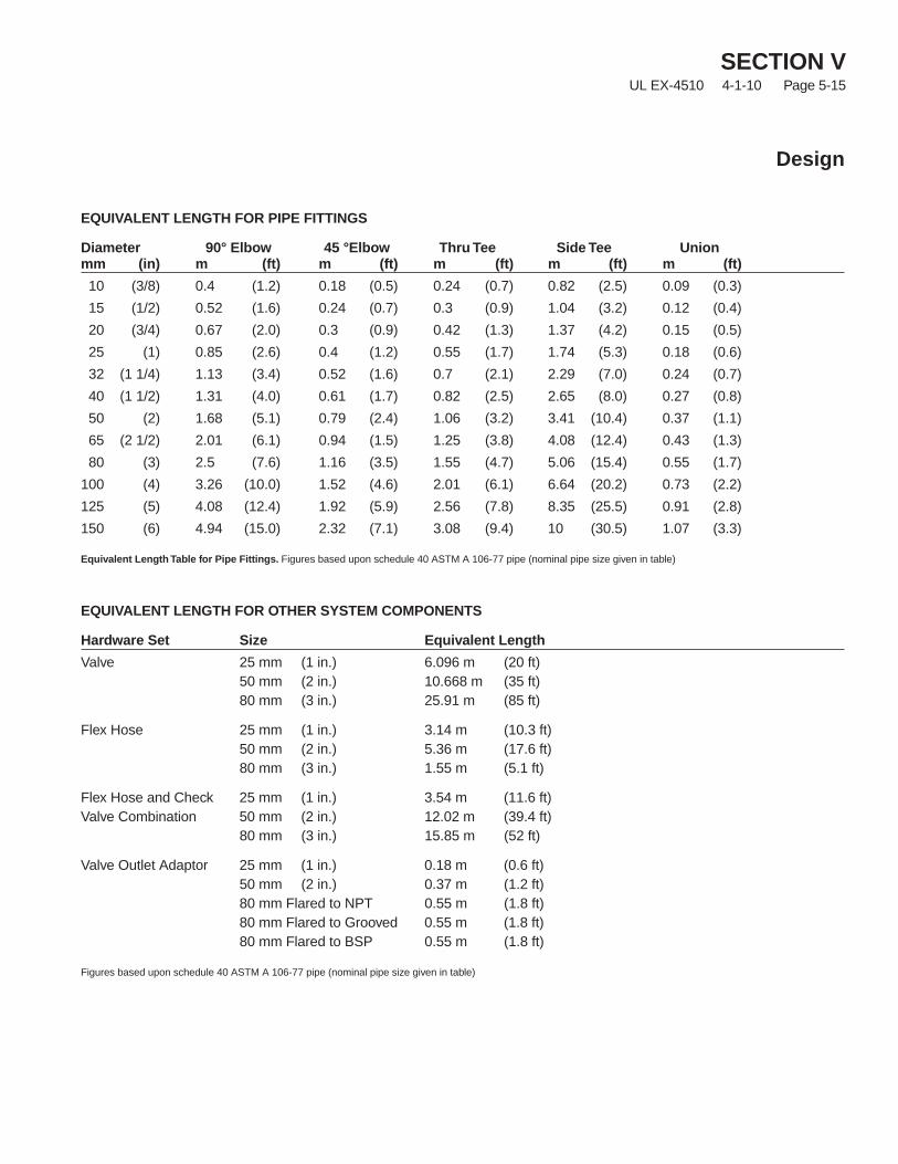
EQUIVALENT LENGTH FOR PIPE FITTINGS
Diameter 90° Elbow 45 °Elbow Thru Tee Side Tee Unionmm (in) m (ft) m (ft) m (ft) m (ft) m (ft)
10 (3/8) 0.4 (1.2) 0.18 (0.5) 0.24 (0.7) 0.82 (2.5) 0.09 (0.3)
15 (1/2) 0.52 (1.6) 0.24 (0.7) 0.3 (0.9) 1.04 (3.2) 0.12 (0.4)
20 (3/4) 0.67 (2.0) 0.3 (0.9) 0.42 (1.3) 1.37 (4.2) 0.15 (0.5)
25 (1) 0.85 (2.6) 0.4 (1.2) 0.55 (1.7) 1.74 (5.3) 0.18 (0.6)
32 (1 1/4) 1.13 (3.4) 0.52 (1.6) 0.7 (2.1) 2.29 (7.0) 0.24 (0.7)
40 (1 1/2) 1.31 (4.0) 0.61 (1.7) 0.82 (2.5) 2.65 (8.0) 0.27 (0.8)
50 (2) 1.68 (5.1) 0.79 (2.4) 1.06 (3.2) 3.41 (10.4) 0.37 (1.1)
65 (2 1/2) 2.01 (6.1) 0.94 (1.5) 1.25 (3.8) 4.08 (12.4) 0.43 (1.3)
80 (3) 2.5 (7.6) 1.16 (3.5) 1.55 (4.7) 5.06 (15.4) 0.55 (1.7)
100 (4) 3.26 (10.0) 1.52 (4.6) 2.01 (6.1) 6.64 (20.2) 0.73 (2.2)
125 (5) 4.08 (12.4) 1.92 (5.9) 2.56 (7.8) 8.35 (25.5) 0.91 (2.8)
150 (6) 4.94 (15.0) 2.32 (7.1) 3.08 (9.4) 10 (30.5) 1.07 (3.3)
Equivalent Length Table for Pipe Fittings. Figures based upon schedule 40 ASTM A 106-77 pipe (nominal pipe size given in table)
EQUIVALENT LENGTH FOR OTHER SYSTEM COMPONENTS
Hardware Set Size Equivalent Length
Valve 25 mm (1 in.) 6.096 m (20 ft)50 mm (2 in.) 10.668 m (35 ft)80 mm (3 in.) 25.91 m (85 ft)
Flex Hose 25 mm (1 in.) 3.14 m (10.3 ft)50 mm (2 in.) 5.36 m (17.6 ft)80 mm (3 in.) 1.55 m (5.1 ft)
Flex Hose and Check 25 mm (1 in.) 3.54 m (11.6 ft)Valve Combination 50 mm (2 in.) 12.02 m (39.4 ft)
80 mm (3 in.) 15.85 m (52 ft)
Valve Outlet Adaptor 25 mm (1 in.) 0.18 m (0.6 ft)50 mm (2 in.) 0.37 m (1.2 ft)80 mm Flared to NPT 0.55 m (1.8 ft)80 mm Flared to Grooved 0.55 m (1.8 ft)80 mm Flared to BSP 0.55 m (1.8 ft)
Figures based upon schedule 40 ASTM A 106-77 pipe (nominal pipe size given in table)
SECTION VUL EX-4510 4-1-10 Page 5-15
Design

SECTION VUL EX-4510 4-1-10 Page 5-16
Design
NOTES:
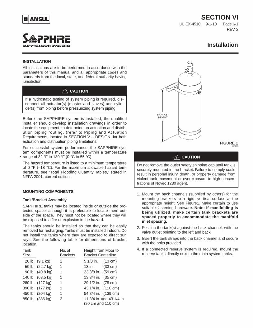
SECTION VIUL EX-4510 9-1-10 Page 6-1
REV. 2
INSTALLATION
All installations are to be performed in accordance with theparameters of this manual and all appropriate codes andstandards from the local, state, and federal authority havingjurisdiction.
Before the SAPPHIRE system is installed, the qualifiedinstaller should develop installation drawings in order tolocate the equipment, to determine an actuation and distrib-ution piping routing, (refer to Piping and ActuationRequirements, located in SECTION V – DESIGN, for bothactuation and distribution piping limitations.
For successful system performance, the SAPPHIRE sys-tem components must be installed within a temperaturerange of 32 °F to 130 °F (0 °C to 55 °C).
The hazard temperature is listed to a minimum temperatureof 0 °F (–18 °C). For the maximum allowable hazard tem-perature, see “Total Flooding Quantity Tables,” stated inNFPA 2001, current edition.
MOUNTING COMPONENTS
Tank/Bracket Assembly
SAPPHIRE tanks may be located inside or outside the pro-tected space, although it is preferable to locate them out-side of the space. They must not be located where they willbe exposed to a fire or explosion in the hazard.
The tanks should be installed so that they can be easilyremoved for recharging. Tanks must be installed indoors. Donot install the tanks where they are exposed to direct sunrays. See the following table for dimensions of bracketlocation.
Tank No. of Height from Floor toSize Brackets Bracket Centerline______ _______ _______________20 lb (9.1 kg) 1 5 1/8 in. (13 cm)50 lb (22.7 kg) 1 13 in. (33 cm)90 lb (40.8 kg) 1 23 3/8 in. (59 cm)
140 lb (63.5 kg) 1 13 3/4 in. (35 cm)280 lb (127 kg) 1 29 1/2 in. (75 cm)390 lb (177 kg) 1 43 1/4 in. (110 cm)450 lb (204 kg) 1 54 3/4 in. (139 cm)850 lb (386 kg) 2 11 3/4 in. and 43 1/4 in.
(30 cm and 110 cm)
FIGURE 1006732
1. Mount the back channels (supplied by others) for themounting brackets to a rigid, vertical surface at theappropriate height. See Figure1. Make certain to usesuitable fastening hardware. Note: If manifolding isbeing utilized, make certain tank brackets arespaced properly to accommodate the manifoldinlet spacing.
2. Position the tank(s) against the back channel, with thevalve outlet pointing to the left and back.
3. Insert the tank straps into the back channel and securewith the bolts provided.
4. If a connected reserve system is required, mount thereserve tanks directly next to the main system tanks.
Installation
CAUTION!
Do not remove the outlet safety shipping cap until tank issecurely mounted in the bracket. Failure to comply couldresult in personal injury, death, or property damage fromviolent tank movement or overexposure to high concen-trations of Novec 1230 agent.
CAUTION!
If a hydrostatic testing of system piping is required, dis-connect all actuator(s) (master and slaves) and cylin-der(s) from piping before pressurizing system piping.
BRACKETHEIGHT
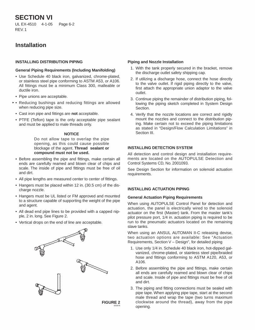
SECTION VIUL EX-4510 4-1-05 Page 6-2REV. 1
Installation
INSTALLING DISTRIBUTION PIPING
General Piping Requirements (Including Manifolding)
• Use Schedule 40 black iron, galvanized, chrome-plated,or stainless steel pipe conforming to ASTM A53, or A106.All fittings must be a minimum Class 300, malleable orductile iron.
• Pipe unions are acceptable.
• Reducing bushings and reducing fittings are allowedwhen reducing pipe size.
• Cast iron pipe and fittings are not acceptable.
• PTFE (Teflon) tape is the only acceptable pipe sealantand must be applied to male threads only.
NOTICEDo not allow tape to overlap the pipeopening, as this could cause possibleblockage of the agent. Thread sealant orcompound must not be used.
• Before assembling the pipe and fittings, make certain allends are carefully reamed and blown clear of chips andscale. The inside of pipe and fittings must be free of oiland dirt.
• All pipe lengths are measured center to center of fittings.
• Hangers must be placed within 12 in. (30.5 cm) of the dis-charge nozzle.
• Hangers must be UL listed or FM approved and mountedto a structure capable of supporting the weight of the pipeand agent.
• All dead end pipe lines to be provided with a capped nip-ple, 2 in. long. See Figure 2.
• Vertical drops on the end of line are acceptable.
FIGURE 2001876
Piping and Nozzle Installation
1. With the tank properly secured in the bracket, removethe discharge outlet safety shipping cap.
2. If utilizing a discharge hose, connect the hose directlyto the valve outlet. If rigid piping directly to the valve,first attach the appropriate union adaptor to the valveoutlet.
3. Continue piping the remainder of distribution piping, fol-lowing the piping sketch completed in System DesignSection.
4. Verify that the nozzle locations are correct and rigidlymount the nozzles and connect to the distribution pip-ing. Make certain not to exceed the piping limitationsas stated in “Design/Flow Calculation Limitations” inSection III.
INSTALLING DETECTION SYSTEM
All detection and control design and installation require-ments are located on the AUTOPULSE Detection andControl Systems CD, No. 2001093.
See Design Section for information on solenoid actuationrequirements.
INSTALLING ACTUATION PIPING
General Actuation Piping Requirements
When using AUTOPULSE Control Panel for detection andactuation, the panel is electrically wired to the solenoidactuator on the first (Master) tank. From the master tank’spilot pressure port, 1/4 in. actuation piping is required to berun to the pneumatic actuators located on the remainingslave tanks.
When using an ANSUL AUTOMAN II-C releasing devise,two actuation options are available: See “ActuationRequirements, Section V – Design”, for detailed piping
1. Use only 1/4 in. Schedule 40 black iron, hot-dipped gal-vanized, chrome-plated, or stainless steel pipe/braidedhose and fittings conforming to ASTM A120, A53, orA106.
2. Before assembling the pipe and fittings, make certainall ends are carefully reamed and blown clear of chipsand scale. Inside of pipe and fittings must be free of oiland dirt.
3. The piping and fitting connections must be sealed withpipe tape. When applying pipe tape, start at the secondmale thread and wrap the tape (two turns maximumclockwise around the thread), away from the pipeopening.
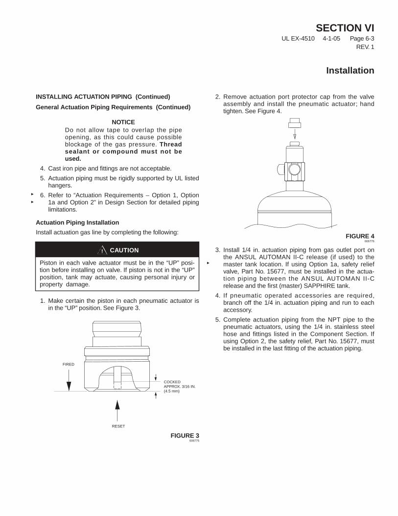
SECTION VIUL EX-4510 4-1-05 Page 6-3
REV. 1
Installation
INSTALLING ACTUATION PIPING (Continued)
General Actuation Piping Requirements (Continued)
NOTICEDo not allow tape to overlap the pipeopening, as this could cause possibleblockage of the gas pressure. Threadsealant or compound must not beused.
4. Cast iron pipe and fittings are not acceptable.
5. Actuation piping must be rigidly supported by UL listedhangers.
6. Refer to “Actuation Requirements – Option 1, Option1a and Option 2” in Design Section for detailed pipinglimitations.
Actuation Piping Installation
Install actuation gas line by completing the following:
1. Make certain the piston in each pneumatic actuator isin the “UP” position. See Figure 3.
FIGURE 3006775
2. Remove actuation port protector cap from the valveassembly and install the pneumatic actuator; handtighten. See Figure 4.
FIGURE 4006776
3. Install 1/4 in. actuation piping from gas outlet port onthe ANSUL AUTOMAN II-C release (if used) to themaster tank location. If using Option 1a, safety reliefvalve, Part No. 15677, must be installed in the actua-tion piping between the ANSUL AUTOMAN II-Crelease and the first (master) SAPPHIRE tank.
4. If pneumatic operated accessories are required,branch off the 1/4 in. actuation piping and run to eachaccessory.
5. Complete actuation piping from the NPT pipe to thepneumatic actuators, using the 1/4 in. stainless steelhose and fittings listed in the Component Section. Ifusing Option 2, the safety relief, Part No. 15677, mustbe installed in the last fitting of the actuation piping.
CAUTION!
Piston in each valve actuator must be in the “UP” posi-tion before installing on valve. If piston is not in the “UP”position, tank may actuate, causing personal injury orproperty damage.
FIRED
RESET
COCKEDAPPROX. 3/16 IN.(4.5 mm)

SECTION VIUL EX-4510 12-1-03 Page 6-4
Installation
NOTES:
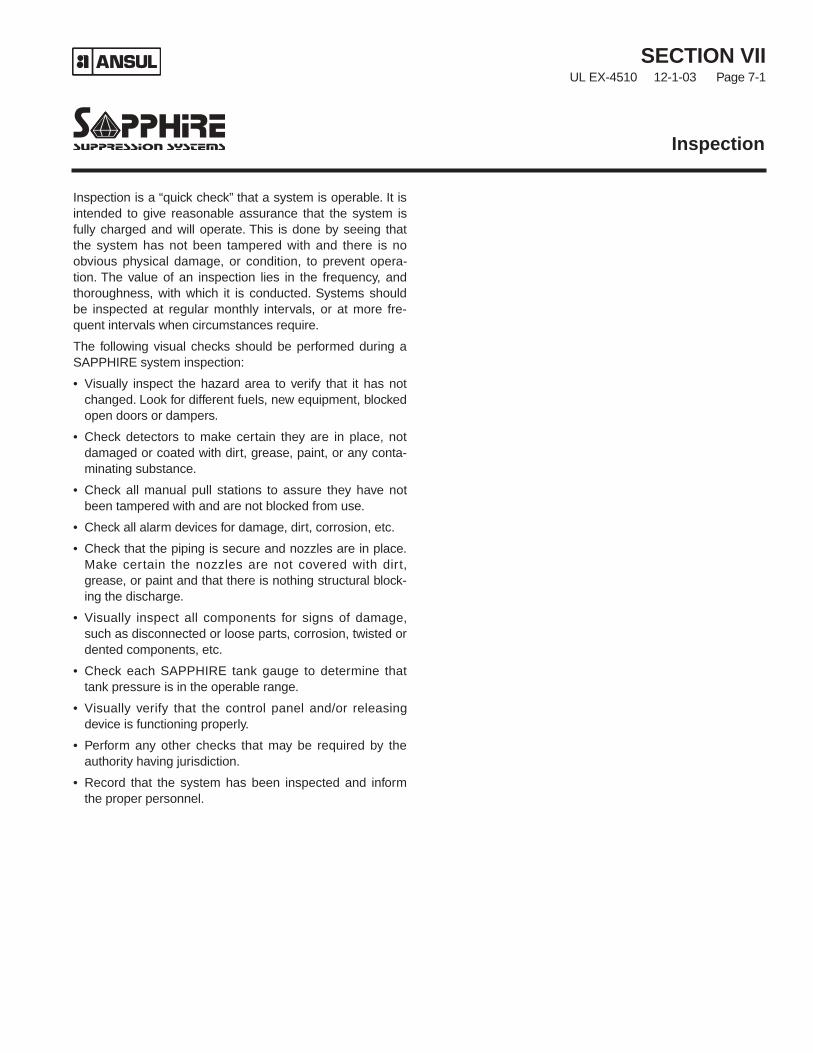
Inspection is a “quick check” that a system is operable. It isintended to give reasonable assurance that the system isfully charged and will operate. This is done by seeing thatthe system has not been tampered with and there is noobvious physical damage, or condition, to prevent opera-tion. The value of an inspection lies in the frequency, andthoroughness, with which it is conducted. Systems shouldbe inspected at regular monthly intervals, or at more fre-quent intervals when circumstances require.
The following visual checks should be performed during aSAPPHIRE system inspection:
• Visually inspect the hazard area to verify that it has notchanged. Look for different fuels, new equipment, blockedopen doors or dampers.
• Check detectors to make certain they are in place, notdamaged or coated with dirt, grease, paint, or any conta-minating substance.
• Check all manual pull stations to assure they have notbeen tampered with and are not blocked from use.
• Check all alarm devices for damage, dirt, corrosion, etc.
• Check that the piping is secure and nozzles are in place.Make certain the nozzles are not covered with dirt,grease, or paint and that there is nothing structural block-ing the discharge.
• Visually inspect all components for signs of damage,such as disconnected or loose parts, corrosion, twisted ordented components, etc.
• Check each SAPPHIRE tank gauge to determine thattank pressure is in the operable range.
• Visually verify that the control panel and/or releasingdevice is functioning properly.
• Perform any other checks that may be required by theauthority having jurisdiction.
• Record that the system has been inspected and informthe proper personnel.
Inspection
SECTION VIIUL EX-4510 12-1-03 Page 7-1

SECTION VIIUL EX-4510 12-1-03 Page 7-2
Inspection
NOTES:
SECTION VIIIUL EX-4510 2-2-09 Page 8-1
REV. 1
ANNUAL MAINTENANCE EXAMINATION
Systems shall be maintained at regular intervals, not morethan one year apart, or when specifically indicated by aninspection. Exception: Tank pressure and agent quantityshall be checked every six months per NFPA 2001.
Maintenance is a “thorough check” of the system. It isintended to give maximum assurance that a system willoperate effectively and safely. It includes a thorough exami-nation and any necessary repair, recharge, or replacement.It will reveal if there is a need for hydrostatic testing of thetank. The procedures listed in this section are the minimumthat are necessary to maintain a system. If circumstanceswarrant them, a more thorough procedure should be fol-lowed to assure system performance. Make certain that allpeople affected by the maintenance are informed beforeyou start. This may include the owner, security personnel,the local Fire Department, and possibly local workers thatmay be affected by equipment shutdown or start up.
NOTICEIf the system includes an ANSULAUTOMAN II-C releasing device, beforeproceeding with annual maintenanceexamination, insert lock pin in ANSULAUTOMAN II-C release and remove nitro-gen cartridge. Install safety shipping capon cartridge.
1. Survey the hazard to make certain it has not changedfrom what the system was designed to protect. Whilesurveying the hazard, look for different fuels, loss ofhazard integrity, new hazards, etc.
2. Check all nozzles to make certain they are in place.Check the condition of the nozzle for corrosion or dam-age and make certain it is not obstructed internally orexternally.
3. Check the condition of the piping to make certain that itis properly secured in the hangers and that all fittingsare connected tightly.
4. Check all warning nameplates (signs) throughout thearea. Make certain they are in place, mounted securely,readable, and are not damaged.
5. Check all tank bracketing. Make certain all tanks aresecured in the brackets. Check for corrosion, damage,or missing components.
6. Check the condition of all tanks. Look for signs of dam-age or corrosion, and check the tank’s last hydro date.(NFPA 2001 states “Cylinders continuously in servicewithout discharging shall be given a complete externalvisual inspection every five years or more frequently ifrequired. The visual inspection shall be in accordancewith Compressed Gas Association Pamphlet C-6,Section 3; except that the cylinders need not be emp-tied or stamped while under pressure.”) Refer to NFPA2001, Chapter 4 Inspection, Maintenance, Testing, andTraining, for hydro requirements.
7. Check condition of all tank discharge hoses. Look forsigns of structural problems like abrasions or weatherchecking. Make certain all hoses are connected prop-erly. All hoses must be tested every 5 years. Refer toNFPA 2001, Chapter 4 Inspection, Maintenance,Testing, and Training, for detailed testing requirements.
8. Check condition of all actuators by completing the fol-lowing:
• Remove all actuators from the tank valves (elec-tric, manual, and pneumatic) and leave them offuntil the final step in Maintenance Section.
• For pneumatic actuators, check the condition ofeach actuator to make certain they operate freely.When finished, reset the pin in the up position. Donot install on tank valves.
• For electric actuators, make certain all wires areproperly connected. Do not install on tankvalves.
NOTICEBefore proceeding with Step No. 9, makecertain all electric actuators have beenremoved from all valves and that the nitro-gen cartridge has been removed from theANSUL AUTOMAN II-C release and thatthe locking pin in the release mechanismhas also been removed.
Maintenance
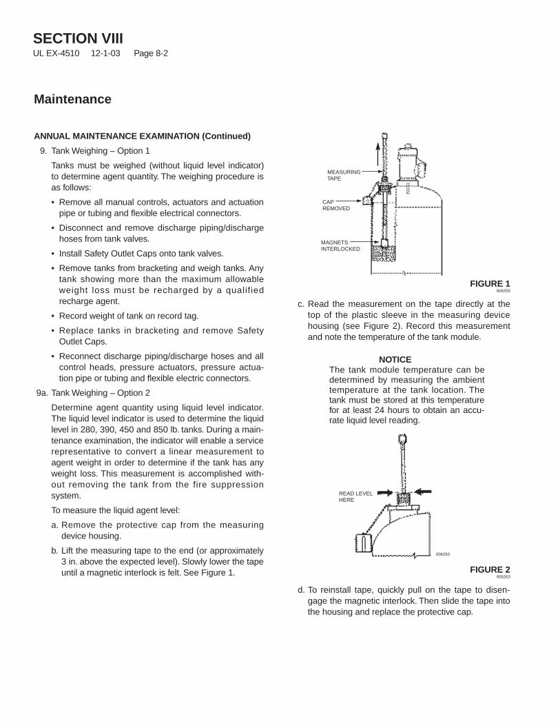
SECTION VIIIUL EX-4510 12-1-03 Page 8-2
Maintenance
ANNUAL MAINTENANCE EXAMINATION (Continued)
9. Tank Weighing – Option 1
Tanks must be weighed (without liquid level indicator)to determine agent quantity. The weighing procedure isas follows:
• Remove all manual controls, actuators and actuationpipe or tubing and flexible electrical connectors.
• Disconnect and remove discharge piping/dischargehoses from tank valves.
• Install Safety Outlet Caps onto tank valves.
• Remove tanks from bracketing and weigh tanks. Anytank showing more than the maximum allowableweight loss must be recharged by a qualifiedrecharge agent.
• Record weight of tank on record tag.
• Replace tanks in bracketing and remove SafetyOutlet Caps.
• Reconnect discharge piping/discharge hoses and allcontrol heads, pressure actuators, pressure actua-tion pipe or tubing and flexible electric connectors.
9a. Tank Weighing – Option 2
Determine agent quantity using liquid level indicator.The liquid level indicator is used to determine the liquidlevel in 280, 390, 450 and 850 lb. tanks. During a main-tenance examination, the indicator will enable a servicerepresentative to convert a linear measurement toagent weight in order to determine if the tank has anyweight loss. This measurement is accomplished with-out removing the tank from the fire suppressionsystem.
To measure the liquid agent level:
a. Remove the protective cap from the measuringdevice housing.
b. Lift the measuring tape to the end (or approximately3 in. above the expected level). Slowly lower the tapeuntil a magnetic interlock is felt. See Figure 1.
FIGURE 1006255
c. Read the measurement on the tape directly at thetop of the plastic sleeve in the measuring devicehousing (see Figure 2). Record this measurementand note the temperature of the tank module.
NOTICEThe tank module temperature can bedetermined by measuring the ambienttemperature at the tank location. Thetank must be stored at this temperaturefor at least 24 hours to obtain an accu-rate liquid level reading.
FIGURE 2006263
d. To reinstall tape, quickly pull on the tape to disen-gage the magnetic interlock. Then slide the tape intothe housing and replace the protective cap.
MEASURINGTAPE
MAGNETSINTERLOCKED
CAPREMOVED
READ LEVELHERE
006263

SECTION VIIIUL EX-4510 12-1-03 Page 8-3
Maintenance
ANNUAL MAINTENANCE EXAMINATION (Continued)
e. Using the Agent Quantity Table(s) located in this sec-tion, determine the weight of charge as follows:
• Find the liquid level reading along the left handvertical line of the table.
• From that point, follow the horizontal line to thepoint where it intersects with the temperature col-umn (using the tank temperature noted in Step c).
• Read the weight of Novec 1230 agent at thelevel/temperature column intersection.
f. Compare the weight from the table to the weight ofcharge stamped on the tank nameplate. If the mea-surement shows a net weight loss of more than 5%,the tank must be weighed to verify the liquid level mea-surement. If the weight loss still exceeds 5% of theweight of charge, the tank requires recharging.
10. Check condition of control panel for tampering, corro-sion, or damage. Test panel at this point by referring tothe appropriate AUTOPULSE Control System manual.Note: If system includes an ANSUL AUTOMAN II-Crelease, make certain cartridge is removed, release iscocked, and locking pin is not in place before each test.
11. Check all detectors. Make certain they are in place,clean, and not damaged. If required, check the sensi-tivity of each per the instructions of the detector manu-facturer. See appropriate AUTOPULSE Control Systemmanual for detailed instructions.
12. Check all pull stations. Make certain they are in place,that they are not blocked or damaged. Operate eachpull station to make certain that they operate the con-trol panel. Reset each pull station.
13. While checking the detectors and electric pull stations,inspect each alarm device. Check the alarm’s conditionand verify that they operate properly when energized.Reset the alarm circuit after each test.
14. If the system includes an ANSUL AUTOMAN, checkrelease by completing the following:
• Make certain locking pin is not in place, and man-ually test release by operating the “STRIKE” but-ton on the release mechanism.
• Cock ANSUL AUTOMAN II-C release using cock-ing lever, Part No. 26310, and install locking pin.
• Remove gasket from cartridge receiver in ANSULAUTOMAN II-C release mechanism. Check gasketfor elasticity or cuts and replace if necessary.Clean and coat gasket lightly with a good grade ofextreme temperature grease such as Dow CorningNo. 4. Reinstall gasket into cartridge receiver. Donot install cartridge at this time.
15. When all tests are complete, reset control panel and allaccessory electrical equipment.
16. Make certain all electric and pneumatic actuators arereset.
17. Install all electric and pneumatic actuators on tankvalves. Hand tighten.
18. Install nitrogen cartridge in ANSUL AUTOMAN II-Crelease by completing the following:
• Make certain release mechanism is cocked andlocking bar is in place.
• Remove shipping cap and weigh nitrogen car-tridge. Replace if weight is 1/2 oz. (14.2 g), ormore, below the weight stamped on the cartridge.
• Screw cartridge into release mechanism, handtighten.
• Remove locking pin.
• Close cover on enclosure, install locking pinthrough “STRIKE” button, and secure with visualseal, Part No. 197.
19. Record annual maintenance date on tag attached tounit and/or in a permanent file.
20. Inform proper personnel that the system is back in ser-vice.
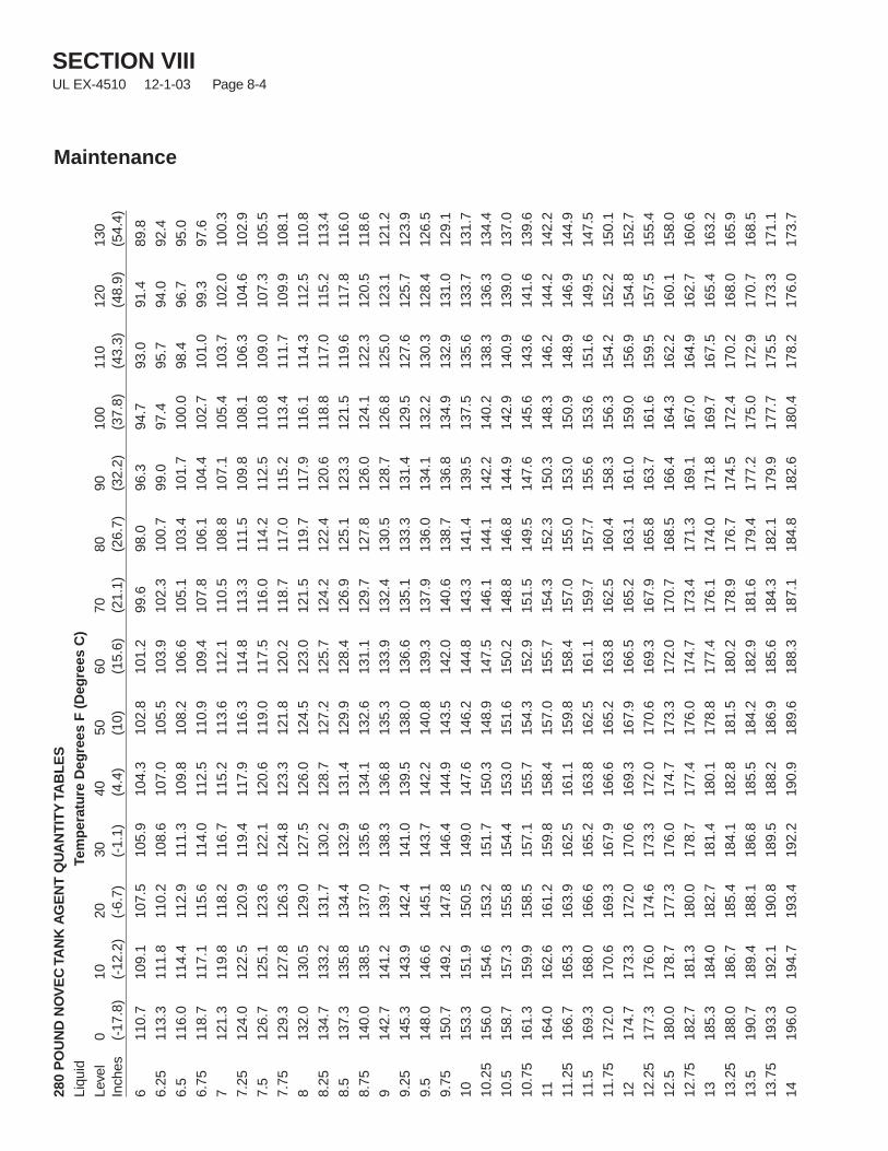
SECTION VIIIUL EX-4510 12-1-03 Page 8-4
Maintenance
280
PO
UN
DN
OV
EC
TAN
KA
GE
NT
QU
AN
TIT
YTA
BL
ES
Liqu
idTe
mp
erat
ure
Deg
rees
F(D
egre
esC
)Le
vel
010
2030
4050
6070
8090
100
110
120
130
Inch
es(-
17.8
)(-
12.2
)(-
6.7)
(-1.
1)(4
.4)
(10)
(15.
6)(2
1.1)
(26.
7)(3
2.2)
(37.
8)(4
3.3)
(48.
9)(5
4.4)
611
0.7
109.
110
7.5
105.
910
4.3
102.
810
1.2
99.6
98.0
96.3
94.7
93.0
91.4
89.8
6.25
113.
311
1.8
110.
210
8.6
107.
010
5.5
103.
910
2.3
100.
799
.097
.495
.794
.092
.4
6.5
116.
011
4.4
112.
911
1.3
109.
810
8.2
106.
610
5.1
103.
410
1.7
100.
098
.496
.795
.0
6.75
118.
711
7.1
115.
611
4.0
112.
511
0.9
109.
410
7.8
106.
110
4.4
102.
710
1.0
99.3
97.6
712
1.3
119.
811
8.2
116.
711
5.2
113.
611
2.1
110.
510
8.8
107.
110
5.4
103.
710
2.0
100.
3
7.25
124.
012
2.5
120.
911
9.4
117.
911
6.3
114.
811
3.3
111.
510
9.8
108.
110
6.3
104.
610
2.9
7.5
126.
712
5.1
123.
612
2.1
120.
611
9.0
117.
511
6.0
114.
211
2.5
110.
810
9.0
107.
310
5.5
7.75
129.
312
7.8
126.
312
4.8
123.
312
1.8
120.
211
8.7
117.
011
5.2
113.
411
1.7
109.
910
8.1
813
2.0
130.
512
9.0
127.
512
6.0
124.
512
3.0
121.
511
9.7
117.
911
6.1
114.
311
2.5
110.
8
8.25
134.
713
3.2
131.
713
0.2
128.
712
7.2
125.
712
4.2
122.
412
0.6
118.
811
7.0
115.
211
3.4
8.5
137.
313
5.8
134.
413
2.9
131.
412
9.9
128.
412
6.9
125.
112
3.3
121.
511
9.6
117.
811
6.0
8.75
140.
013
8.5
137.
013
5.6
134.
113
2.6
131.
112
9.7
127.
812
6.0
124.
112
2.3
120.
511
8.6
914
2.7
141.
213
9.7
138.
313
6.8
135.
313
3.9
132.
413
0.5
128.
712
6.8
125.
012
3.1
121.
2
9.25
145.
314
3.9
142.
414
1.0
139.
513
8.0
136.
613
5.1
133.
313
1.4
129.
512
7.6
125.
712
3.9
9.5
148.
014
6.6
145.
114
3.7
142.
214
0.8
139.
313
7.9
136.
013
4.1
132.
213
0.3
128.
412
6.5
9.75
150.
714
9.2
147.
814
6.4
144.
914
3.5
142.
014
0.6
138.
713
6.8
134.
913
2.9
131.
012
9.1
1015
3.3
151.
915
0.5
149.
014
7.6
146.
214
4.8
143.
314
1.4
139.
513
7.5
135.
613
3.7
131.
7
10.2
515
6.0
154.
615
3.2
151.
715
0.3
148.
914
7.5
146.
114
4.1
142.
214
0.2
138.
313
6.3
134.
4
10.5
158.
715
7.3
155.
815
4.4
153.
015
1.6
150.
214
8.8
146.
814
4.9
142.
914
0.9
139.
013
7.0
10.7
516
1.3
159.
915
8.5
157.
115
5.7
154.
315
2.9
151.
514
9.5
147.
614
5.6
143.
614
1.6
139.
6
1116
4.0
162.
616
1.2
159.
815
8.4
157.
015
5.7
154.
315
2.3
150.
314
8.3
146.
214
4.2
142.
2
11.2
516
6.7
165.
316
3.9
162.
516
1.1
159.
815
8.4
157.
015
5.0
153.
015
0.9
148.
914
6.9
144.
9
11.5
169.
316
8.0
166.
616
5.2
163.
816
2.5
161.
115
9.7
157.
715
5.6
153.
615
1.6
149.
514
7.5
11.7
517
2.0
170.
616
9.3
167.
916
6.6
165.
216
3.8
162.
516
0.4
158.
315
6.3
154.
215
2.2
150.
1
1217
4.7
173.
317
2.0
170.
616
9.3
167.
916
6.5
165.
216
3.1
161.
015
9.0
156.
915
4.8
152.
7
12.2
517
7.3
176.
017
4.6
173.
317
2.0
170.
616
9.3
167.
916
5.8
163.
716
1.6
159.
515
7.5
155.
4
12.5
180.
017
8.7
177.
317
6.0
174.
717
3.3
172.
017
0.7
168.
516
6.4
164.
316
2.2
160.
115
8.0
12.7
518
2.7
181.
318
0.0
178.
717
7.4
176.
017
4.7
173.
417
1.3
169.
116
7.0
164.
916
2.7
160.
6
1318
5.3
184.
018
2.7
181.
418
0.1
178.
817
7.4
176.
117
4.0
171.
816
9.7
167.
516
5.4
163.
2
13.2
518
8.0
186.
718
5.4
184.
118
2.8
181.
518
0.2
178.
917
6.7
174.
517
2.4
170.
216
8.0
165.
9
13.5
190.
718
9.4
188.
118
6.8
185.
518
4.2
182.
918
1.6
179.
417
7.2
175.
017
2.9
170.
716
8.5
13.7
519
3.3
192.
119
0.8
189.
518
8.2
186.
918
5.6
184.
318
2.1
179.
917
7.7
175.
517
3.3
171.
1
1419
6.0
194.
719
3.4
192.
219
0.9
189.
618
8.3
187.
118
4.8
182.
618
0.4
178.
217
6.0
173.
7
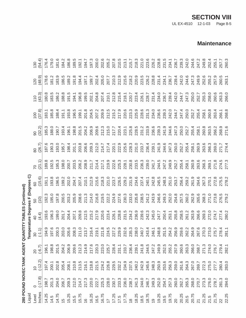
SECTION VIIIUL EX-4510 12-1-03 Page 8-5
Maintenance
280
PO
UN
DN
OV
EC
TAN
KA
GE
NT
QU
AN
TIT
YTA
BL
ES
(Co
nti
nu
ed)
Liqu
idTe
mp
erat
ure
Deg
rees
F(D
egre
esC
)Le
vel
010
2030
4050
6070
8090
100
110
120
130
Inch
es(-
17.8
)(-
12.2
)(-
6.7)
(-1.
1)(4
.4)
(10)
(15.
6)(2
1.1)
(26.
7)(3
2.2)
(37.
8)(4
3.3)
(48.
9)(5
4.4)
14.2
519
8.7
197.
419
6.1
194.
919
3.6
192.
319
1.1
189.
818
7.6
185.
318
3.1
180.
817
8.6
176.
4
14.5
201.
320
0.1
198.
819
7.6
196.
319
5.0
193.
819
2.5
190.
318
8.0
185.
818
3.5
181.
217
9.0
14.7
520
4.0
202.
820
1.5
200.
319
9.0
197.
819
6.5
195.
319
3.0
190.
718
8.4
186.
218
3.9
181.
6
1520
6.7
205.
420
4.2
203.
020
1.7
200.
519
9.2
198.
019
5.7
193.
419
1.1
188.
818
6.5
184.
2
15.2
520
9.3
208.
120
6.9
205.
620
4.4
203.
220
2.0
200.
719
8.4
196.
119
3.8
191.
518
9.2
186.
8
15.5
212.
021
0.8
209.
620
8.3
207.
120
5.9
204.
720
3.5
201.
119
8.8
196.
519
4.1
191.
818
9.5
15.7
521
4.7
213.
521
2.3
211.
020
9.8
208.
620
7.4
206.
220
3.8
201.
519
9.1
196.
819
4.4
192.
1
1621
7.3
216.
121
4.9
213.
721
2.5
211.
321
0.1
208.
920
6.6
204.
220
1.8
199.
519
7.1
194.
7
16.2
522
0.0
218.
821
7.6
216.
421
5.2
214.
021
2.9
211.
720
9.3
206.
920
4.5
202.
119
9.7
197.
3
16.5
222.
722
1.5
220.
321
9.1
217.
921
6.8
215.
621
4.4
212.
020
9.6
207.
220
4.8
202.
420
0.0
16.7
522
5.3
224.
222
3.0
221.
822
0.6
219.
521
8.3
217.
121
4.7
212.
320
9.9
207.
420
5.0
202.
6
1722
8.0
226.
822
5.7
224.
522
3.4
222.
222
1.0
219.
921
7.4
215.
021
2.5
210.
120
7.7
205.
2
17.2
523
0.7
229.
522
8.4
227.
222
6.1
224.
922
3.7
222.
622
0.1
217.
721
5.2
212.
821
0.3
207.
8
17.5
233.
323
2.2
231.
122
9.9
228.
822
7.6
226.
522
5.3
222.
922
0.4
217.
921
5.4
212.
921
0.5
17.7
523
6.0
234.
923
3.7
232.
623
1.5
230.
322
9.2
228.
122
5.6
223.
122
0.6
218.
121
5.6
213.
1
1823
8.7
237.
523
6.4
235.
323
4.2
233.
023
1.9
230.
822
8.3
225.
822
3.3
220.
721
8.2
215.
7
18.2
524
1.3
240.
223
9.1
238.
023
6.9
235.
823
4.6
233.
523
1.0
228.
522
5.9
223.
422
0.9
218.
3
18.5
244.
024
2.9
241.
824
0.7
239.
623
8.5
237.
423
6.3
233.
723
1.2
228.
622
6.1
223.
522
1.0
18.7
524
6.7
245.
624
4.5
243.
424
2.3
241.
224
0.1
239.
023
6.4
233.
923
1.3
228.
722
6.2
223.
6
1924
9.3
248.
324
7.2
246.
124
5.0
243.
924
2.8
241.
723
9.1
236.
623
4.0
231.
422
8.8
226.
2
19.2
525
2.0
250.
924
9.9
248.
824
7.7
246.
624
5.5
244.
524
1.9
239.
323
6.6
234.
023
1.4
228.
8
19.5
254.
725
3.6
252.
525
1.5
250.
424
9.3
248.
324
7.2
244.
624
1.9
239.
323
6.7
234.
123
1.5
19.7
525
7.3
256.
325
5.2
254.
225
3.1
252.
025
1.0
249.
924
7.3
244.
624
2.0
239.
423
6.7
234.
1
2026
0.0
259.
025
7.9
256.
925
5.8
254.
825
3.7
252.
725
0.0
247.
324
4.7
242.
023
9.4
236.
7
20.2
526
2.7
261.
626
0.6
259.
625
8.5
257.
525
6.4
255.
425
2.7
250.
024
7.4
244.
724
2.0
239.
3
20.5
265.
326
4.3
263.
326
2.2
261.
226
0.2
259.
225
8.1
255.
425
2.7
250.
024
7.3
244.
624
2.0
20.7
526
8.0
267.
026
6.0
264.
926
3.9
262.
926
1.9
260.
925
8.1
255.
425
2.7
250.
024
7.3
244.
6
2127
0.7
269.
726
8.7
267.
626
6.6
265.
626
4.6
263.
626
0.9
258.
125
5.4
252.
724
9.9
247.
2
21.2
527
3.3
272.
327
1.3
270.
326
9.3
268.
326
7.3
266.
326
3.6
260.
825
8.1
255.
325
2.6
249.
8
21.5
276.
027
5.0
274.
027
3.0
272.
027
1.0
270.
126
9.1
266.
326
3.5
260.
825
8.0
255.
225
2.4
21.7
527
8.7
277.
727
6.7
275.
727
4.7
273.
827
2.8
271.
826
9.0
266.
226
3.4
260.
625
7.9
255.
1
2228
1.3
280.
427
9.4
278.
427
7.4
276.
527
5.5
274.
527
1.7
268.
926
6.1
263.
326
0.5
257.
7
22.2
528
4.0
283.
028
2.1
281.
128
0.2
279.
227
8.2
277.
327
4.4
271.
626
8.8
266.
026
3.1
260.
3
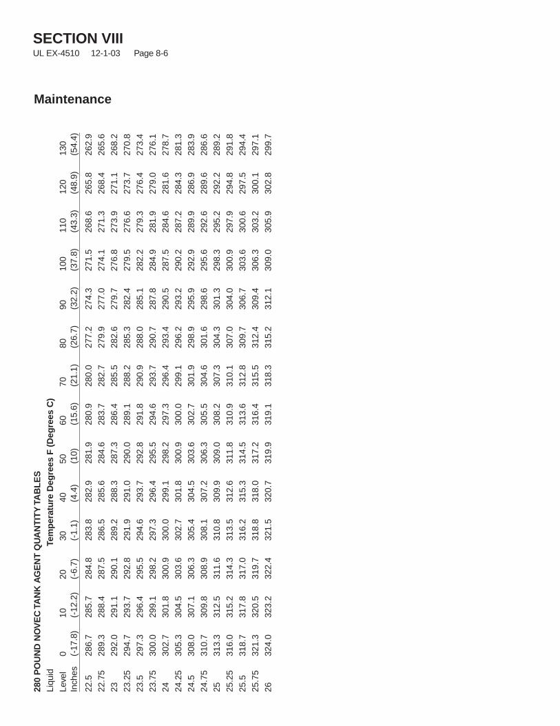
SECTION VIIIUL EX-4510 12-1-03 Page 8-6
Maintenance
280
PO
UN
DN
OV
EC
TAN
KA
GE
NT
QU
AN
TIT
YTA
BL
ES
Liqu
idTe
mp
erat
ure
Deg
rees
F(D
egre
esC
)Le
vel
010
2030
4050
6070
8090
100
110
120
130
Inch
es(-
17.8
)(-
12.2
)(-
6.7)
(-1.
1)(4
.4)
(10)
(15.
6)(2
1.1)
(26.
7)(3
2.2)
(37.
8)(4
3.3)
(48.
9)(5
4.4)
22.5
286.
728
5.7
284.
828
3.8
282.
928
1.9
280.
928
0.0
277.
227
4.3
271.
526
8.6
265.
826
2.9
22.7
528
9.3
288.
428
7.5
286.
528
5.6
284.
628
3.7
282.
727
9.9
277.
027
4.1
271.
326
8.4
265.
6
2329
2.0
291.
129
0.1
289.
228
8.3
287.
328
6.4
285.
528
2.6
279.
727
6.8
273.
927
1.1
268.
2
23.2
529
4.7
293.
729
2.8
291.
929
1.0
290.
028
9.1
288.
228
5.3
282.
427
9.5
276.
627
3.7
270.
8
23.5
297.
329
6.4
295.
529
4.6
293.
729
2.8
291.
829
0.9
288.
028
5.1
282.
227
9.3
276.
427
3.4
23.7
530
0.0
299.
129
8.2
297.
329
6.4
295.
529
4.6
293.
729
0.7
287.
828
4.9
281.
927
9.0
276.
1
2430
2.7
301.
830
0.9
300.
029
9.1
298.
229
7.3
296.
429
3.4
290.
528
7.5
284.
628
1.6
278.
7
24.2
530
5.3
304.
530
3.6
302.
730
1.8
300.
930
0.0
299.
129
6.2
293.
229
0.2
287.
228
4.3
281.
3
24.5
308.
030
7.1
306.
330
5.4
304.
530
3.6
302.
730
1.9
298.
929
5.9
292.
928
9.9
286.
928
3.9
24.7
531
0.7
309.
830
8.9
308.
130
7.2
306.
330
5.5
304.
630
1.6
298.
629
5.6
292.
628
9.6
286.
6
2531
3.3
312.
531
1.6
310.
830
9.9
309.
030
8.2
307.
330
4.3
301.
329
8.3
295.
229
2.2
289.
2
25.2
531
6.0
315.
231
4.3
313.
531
2.6
311.
831
0.9
310.
130
7.0
304.
030
0.9
297.
929
4.8
291.
8
25.5
318.
731
7.8
317.
031
6.2
315.
331
4.5
313.
631
2.8
309.
730
6.7
303.
630
0.6
297.
529
4.4
25.7
532
1.3
320.
531
9.7
318.
831
8.0
317.
231
6.4
315.
531
2.4
309.
430
6.3
303.
230
0.1
297.
1
2632
4.0
323.
232
2.4
321.
532
0.7
319.
931
9.1
318.
331
5.2
312.
130
9.0
305.
930
2.8
299.
7
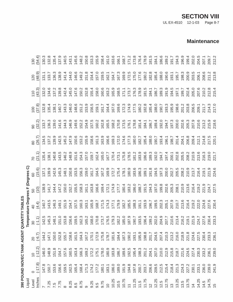
SECTION VIIIUL EX-4510 12-1-03 Page 8-7
Maintenance
390
PO
UN
DN
OV
EC
TAN
KA
GE
NT
QU
AN
TIT
YTA
BL
ES
Liqu
idTe
mp
erat
ure
Deg
rees
F(D
egre
esC
)Le
vel
010
2030
4050
6070
8090
100
110
120
130
Inch
es(-
17.8
)(-
12.2
)(-
6.7)
(-1.
1)(4
.4)
(10)
(15.
6)(2
1.1)
(26.
7)(3
2.2)
(37.
8)(4
3.3)
(48.
9)(5
4.4)
714
7.8
146.
014
4.2
142.
514
0.7
138.
913
7.1
135.
413
4.5
133.
713
2.8
132.
013
1.1
130.
3
7.25
150.
714
8.9
147.
114
5.3
143.
514
1.7
139.
913
8.1
137.
213
6.3
135.
413
4.6
133.
713
2.8
7.5
153.
615
1.8
150.
014
8.1
146.
314
4.4
142.
614
0.8
139.
913
9.0
138.
113
7.2
136.
313
5.4
7.75
156.
615
4.7
152.
815
1.0
149.
114
7.2
145.
314
3.5
142.
514
1.6
140.
713
9.8
138.
913
7.9
815
9.5
157.
615
5.7
153.
815
1.9
150.
014
8.1
146.
214
5.2
144.
314
3.3
142.
414
1.4
140.
5
8.25
162.
516
0.5
158.
615
6.6
154.
715
2.7
150.
814
8.9
147.
914
6.9
146.
014
5.0
144.
014
3.1
8.5
165.
416
3.4
161.
515
9.5
157.
515
5.5
153.
515
1.6
150.
614
9.6
148.
614
7.6
146.
614
5.6
8.75
168.
416
6.3
164.
316
2.3
160.
315
8.3
156.
315
4.3
153.
215
2.2
151.
215
0.2
149.
214
8.2
917
1.3
169.
216
7.2
165.
216
3.1
161.
115
9.0
157.
015
5.9
154.
915
3.9
152.
815
1.8
150.
8
9.25
174.
217
2.2
170.
116
8.0
165.
916
3.8
161.
715
9.7
158.
615
7.5
156.
515
5.4
154.
415
3.3
9.5
177.
217
5.1
172.
917
0.8
168.
716
6.6
164.
516
2.4
161.
316
0.2
159.
115
8.0
157.
015
5.9
9.75
180.
117
8.0
175.
817
3.7
171.
516
9.4
167.
216
5.0
163.
916
2.8
161.
716
0.6
159.
515
8.4
1018
3.1
180.
917
8.7
176.
517
4.3
172.
116
9.9
167.
716
6.6
165.
516
4.4
163.
216
2.1
161.
0
10.2
518
6.0
183.
818
1.6
179.
317
7.1
174.
917
2.7
170.
416
9.3
168.
216
7.0
165.
916
4.7
163.
6
10.5
189.
018
6.7
184.
418
2.2
179.
917
7.7
175.
417
3.1
172.
017
0.8
169.
616
8.5
167.
316
6.1
10.7
519
1.9
189.
618
7.3
185.
018
2.7
180.
417
8.1
175.
817
4.6
173.
517
2.3
171.
116
9.9
168.
7
1119
4.8
192.
519
0.2
187.
918
5.5
183.
218
0.9
178.
517
7.3
176.
117
4.9
173.
717
2.5
171.
2
11.2
519
7.8
195.
419
3.1
190.
718
8.3
186.
018
3.6
181.
218
0.0
178.
817
7.5
176.
317
5.0
173.
8
11.5
200.
719
8.3
195.
919
3.5
191.
118
8.7
186.
318
3.9
182.
718
1.4
180.
217
8.9
177.
617
6.4
11.7
520
3.7
201.
219
8.8
196.
419
3.9
191.
518
9.1
186.
618
5.4
184.
118
2.8
181.
518
0.2
178.
9
1220
6.6
204.
120
1.7
199.
219
6.7
194.
319
1.8
189.
318
8.0
186.
718
5.4
184.
118
2.8
181.
5
12.2
520
9.5
207.
020
4.5
202.
019
9.5
197.
019
4.5
192.
019
0.7
189.
418
8.0
186.
718
5.4
184.
1
12.5
212.
521
0.0
207.
420
4.9
202.
319
9.8
197.
319
4.7
193.
419
2.0
190.
718
9.3
188.
018
6.6
12.7
521
5.4
212.
921
0.3
207.
720
5.1
202.
620
0.0
197.
419
6.1
194.
719
3.3
191.
919
0.6
189.
2
1321
8.4
215.
821
3.2
210.
620
7.9
205.
320
2.7
200.
119
8.7
197.
319
5.9
194.
519
3.1
191.
7
13.2
522
1.3
218.
721
6.0
213.
421
0.7
208.
120
5.5
202.
820
1.4
200.
019
8.6
197.
119
5.7
194.
3
13.5
224.
322
1.6
218.
921
6.2
213.
621
0.9
208.
220
5.5
204.
120
2.6
201.
219
9.7
198.
319
6.9
13.7
522
7.2
224.
522
1.8
219.
121
6.4
213.
621
0.9
208.
220
6.8
205.
320
3.8
202.
420
0.9
199.
4
1423
0.1
227.
422
4.6
221.
921
9.2
216.
421
3.7
210.
920
9.4
207.
920
6.5
205.
020
3.5
202.
0
14.2
523
3.1
230.
322
7.5
224.
722
2.0
219.
221
6.4
213.
621
2.1
210.
620
9.1
207.
620
6.1
204.
5
14.5
236.
023
3.2
230.
422
7.6
224.
822
1.9
219.
121
6.3
214.
821
3.2
211.
721
0.2
208.
620
7.1
14.7
523
9.0
236.
123
3.3
230.
422
7.6
224.
722
1.9
219.
021
7.5
215.
921
4.3
212.
821
1.2
209.
7
1524
1.9
239.
023
6.1
233.
323
0.4
227.
522
4.6
221.
722
0.1
218.
621
7.0
215.
421
3.8
212.
2

SECTION VIIIUL EX-4510 12-1-03 Page 8-8
Maintenance
390
PO
UN
DN
OV
EC
TAN
KA
GE
NT
QU
AN
TIT
YTA
BL
ES
Liqu
idTe
mp
erat
ure
Deg
rees
F(D
egre
esC
)Le
vel
010
2030
4050
6070
8090
100
110
120
130
Inch
es(-
17.8
)(-
12.2
)(-
6.7)
(-1.
1)(4
.4)
(10)
(15.
6)(2
1.1)
(26.
7)(3
2.2)
(37.
8)(4
3.3)
(48.
9)(5
4.4)
15.2
524
4.8
241.
923
9.0
236.
123
3.2
230.
222
7.3
224.
422
2.8
221.
221
9.6
218.
021
6.4
214.
8
15.5
247.
824
4.8
241.
923
8.9
236.
023
3.0
230.
122
7.1
225.
522
3.9
222.
222
0.6
219.
021
7.4
15.7
525
0.7
247.
724
4.8
241.
823
8.8
235.
823
2.8
229.
822
8.2
226.
522
4.9
223.
222
1.6
219.
9
1625
3.7
250.
724
7.6
244.
624
1.6
238.
623
5.5
232.
523
0.8
229.
222
7.5
225.
822
4.2
222.
5
16.2
525
6.6
253.
625
0.5
247.
424
4.4
241.
323
8.3
235.
223
3.5
231.
823
0.1
228.
422
6.7
225.
0
16.5
259.
625
6.5
253.
425
0.3
247.
224
4.1
241.
023
7.9
236.
223
4.5
232.
823
1.0
229.
322
7.6
16.7
526
2.5
259.
425
6.2
253.
125
0.0
246.
924
3.7
240.
623
8.9
237.
123
5.4
233.
623
1.9
230.
2
1726
5.4
262.
325
9.1
256.
025
2.8
249.
624
6.5
243.
324
1.5
239.
823
8.0
236.
323
4.5
232.
7
17.2
526
8.4
265.
226
2.0
258.
825
5.6
252.
424
9.2
246.
024
4.2
242.
424
0.6
238.
923
7.1
235.
3
17.5
271.
326
8.1
264.
926
1.6
258.
425
5.2
251.
924
8.7
246.
924
5.1
243.
324
1.5
239.
723
7.9
17.7
527
4.3
271.
026
7.7
264.
526
1.2
257.
925
4.7
251.
424
9.6
247.
724
5.9
244.
124
2.2
240.
4
1827
7.2
273.
927
0.6
267.
326
4.0
260.
725
7.4
254.
125
2.2
250.
424
8.5
246.
724
4.8
243.
0
18.2
528
0.2
276.
827
3.5
270.
126
6.8
263.
526
0.1
256.
825
4.9
253.
025
1.2
249.
324
7.4
245.
5
18.5
283.
127
9.7
276.
427
3.0
269.
626
6.2
262.
925
9.5
257.
625
5.7
253.
825
1.9
250.
024
8.1
18.7
528
6.0
282.
627
9.2
275.
827
2.4
269.
026
5.6
262.
226
0.3
258.
325
6.4
254.
525
2.6
250.
7
1928
9.0
285.
528
2.1
278.
727
5.2
271.
826
8.3
264.
926
2.9
261.
025
9.1
257.
125
5.2
253.
2
19.2
529
1.9
288.
428
5.0
281.
527
8.0
274.
527
1.1
267.
626
5.6
263.
626
1.7
259.
725
7.7
255.
8
19.5
294.
929
1.4
287.
828
4.3
280.
827
7.3
273.
827
0.3
268.
326
6.3
264.
326
2.3
260.
325
8.3
19.7
529
7.8
294.
329
0.7
287.
228
3.6
280.
127
6.5
273.
027
1.0
269.
026
6.9
264.
926
2.9
260.
9
2030
0.7
297.
229
3.6
290.
028
6.4
282.
827
9.3
275.
727
3.6
271.
626
9.6
267.
526
5.5
263.
5
20.2
530
3.7
300.
129
6.5
292.
828
9.2
285.
628
2.0
278.
427
6.3
274.
327
2.2
270.
126
8.1
266.
0
20.5
306.
630
3.0
299.
329
5.7
292.
028
8.4
284.
728
1.1
279.
027
6.9
274.
827
2.8
270.
726
8.6
20.7
530
9.6
305.
930
2.2
298.
529
4.8
291.
128
7.5
283.
828
1.7
279.
627
7.5
275.
427
3.3
271.
2
2131
2.5
308.
830
5.1
301.
429
7.6
293.
929
0.2
286.
528
4.3
282.
228
0.1
278.
027
5.8
273.
7
21.2
531
5.5
311.
730
7.9
304.
230
0.4
296.
729
2.9
289.
228
7.0
284.
928
2.7
280.
627
8.4
276.
3
21.5
318.
431
4.6
310.
830
7.0
303.
229
9.4
295.
729
1.9
289.
728
7.5
285.
428
3.2
281.
027
8.8
21.7
532
1.3
317.
531
3.7
309.
930
6.0
302.
229
8.4
294.
629
2.4
290.
228
8.0
285.
828
3.6
281.
4
2232
4.3
320.
431
6.6
312.
730
8.8
305.
030
1.1
297.
329
5.0
292.
829
0.6
288.
428
6.2
284.
0
22.2
532
7.2
323.
331
9.4
315.
531
1.6
307.
830
3.9
300.
029
7.7
295.
529
3.2
291.
028
8.8
286.
5
22.5
330.
232
6.2
322.
331
8.4
314.
431
0.5
306.
630
2.7
300.
429
8.1
295.
929
3.6
291.
328
9.1
22.7
533
3.1
329.
132
5.2
321.
231
7.3
313.
330
9.3
305.
430
3.1
300.
829
8.5
296.
229
3.9
291.
6
2333
6.1
332.
132
8.1
324.
132
0.1
316.
131
2.1
308.
130
5.7
303.
430
1.1
298.
829
6.5
294.
2
23.2
533
9.0
335.
033
0.9
326.
932
2.9
318.
831
4.8
310.
830
8.4
306.
130
3.8
301.
429
9.1
296.
8
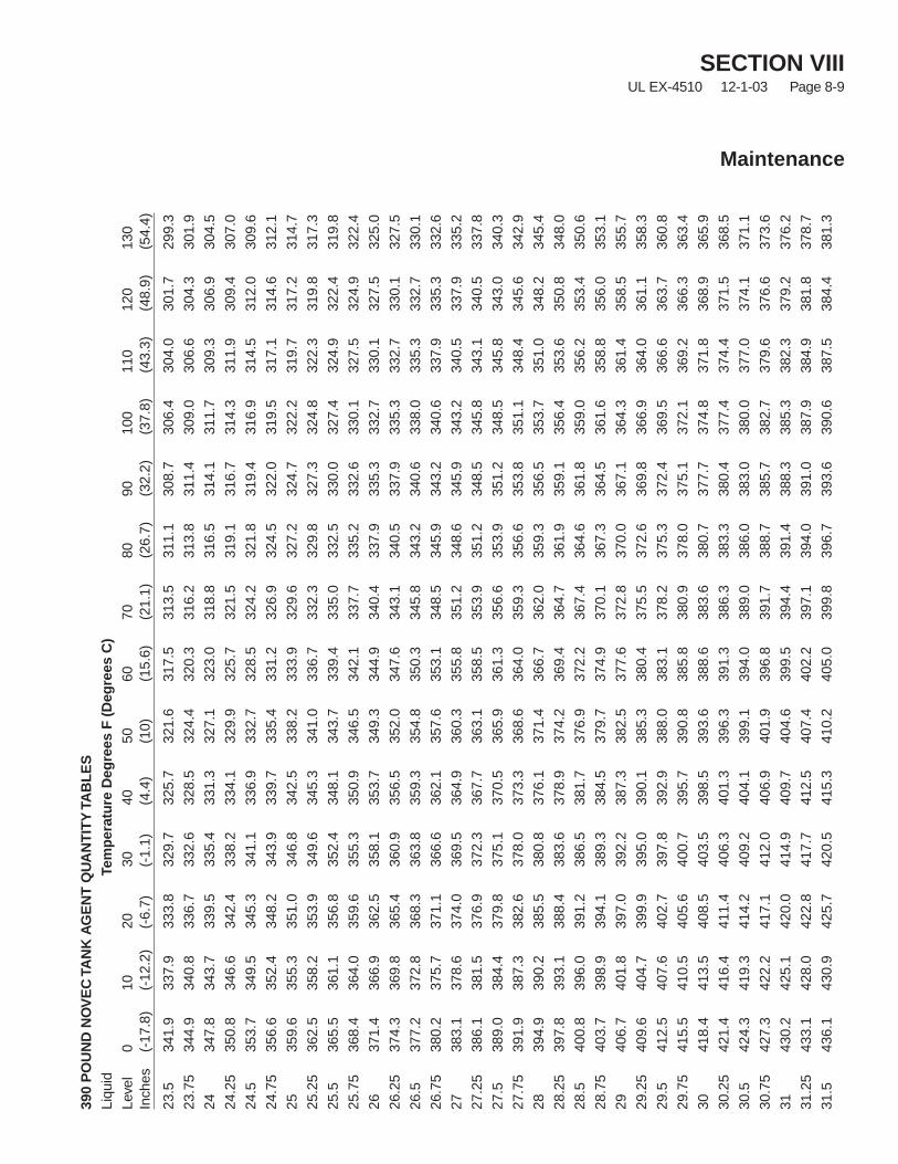
SECTION VIIIUL EX-4510 12-1-03 Page 8-9
Maintenance
390
PO
UN
DN
OV
EC
TAN
KA
GE
NT
QU
AN
TIT
YTA
BL
ES
Liqu
idTe
mp
erat
ure
Deg
rees
F(D
egre
esC
)Le
vel
010
2030
4050
6070
8090
100
110
120
130
Inch
es(-
17.8
)(-
12.2
)(-
6.7)
(-1.
1)(4
.4)
(10)
(15.
6)(2
1.1)
(26.
7)(3
2.2)
(37.
8)(4
3.3)
(48.
9)(5
4.4)
23.5
341.
933
7.9
333.
832
9.7
325.
732
1.6
317.
531
3.5
311.
130
8.7
306.
430
4.0
301.
729
9.3
23.7
534
4.9
340.
833
6.7
332.
632
8.5
324.
432
0.3
316.
231
3.8
311.
430
9.0
306.
630
4.3
301.
9
2434
7.8
343.
733
9.5
335.
433
1.3
327.
132
3.0
318.
831
6.5
314.
131
1.7
309.
330
6.9
304.
5
24.2
535
0.8
346.
634
2.4
338.
233
4.1
329.
932
5.7
321.
531
9.1
316.
731
4.3
311.
930
9.4
307.
0
24.5
353.
734
9.5
345.
334
1.1
336.
933
2.7
328.
532
4.2
321.
831
9.4
316.
931
4.5
312.
030
9.6
24.7
535
6.6
352.
434
8.2
343.
933
9.7
335.
433
1.2
326.
932
4.5
322.
031
9.5
317.
131
4.6
312.
1
2535
9.6
355.
335
1.0
346.
834
2.5
338.
233
3.9
329.
632
7.2
324.
732
2.2
319.
731
7.2
314.
7
25.2
536
2.5
358.
235
3.9
349.
634
5.3
341.
033
6.7
332.
332
9.8
327.
332
4.8
322.
331
9.8
317.
3
25.5
365.
536
1.1
356.
835
2.4
348.
134
3.7
339.
433
5.0
332.
533
0.0
327.
432
4.9
322.
431
9.8
25.7
536
8.4
364.
035
9.6
355.
335
0.9
346.
534
2.1
337.
733
5.2
332.
633
0.1
327.
532
4.9
322.
4
2637
1.4
366.
936
2.5
358.
135
3.7
349.
334
4.9
340.
433
7.9
335.
333
2.7
330.
132
7.5
325.
0
26.2
537
4.3
369.
836
5.4
360.
935
6.5
352.
034
7.6
343.
134
0.5
337.
933
5.3
332.
733
0.1
327.
5
26.5
377.
237
2.8
368.
336
3.8
359.
335
4.8
350.
334
5.8
343.
234
0.6
338.
033
5.3
332.
733
0.1
26.7
538
0.2
375.
737
1.1
366.
636
2.1
357.
635
3.1
348.
534
5.9
343.
234
0.6
337.
933
5.3
332.
6
2738
3.1
378.
637
4.0
369.
536
4.9
360.
335
5.8
351.
234
8.6
345.
934
3.2
340.
533
7.9
335.
2
27.2
538
6.1
381.
537
6.9
372.
336
7.7
363.
135
8.5
353.
935
1.2
348.
534
5.8
343.
134
0.5
337.
8
27.5
389.
038
4.4
379.
837
5.1
370.
536
5.9
361.
335
6.6
353.
935
1.2
348.
534
5.8
343.
034
0.3
27.7
539
1.9
387.
338
2.6
378.
037
3.3
368.
636
4.0
359.
335
6.6
353.
835
1.1
348.
434
5.6
342.
9
2839
4.9
390.
238
5.5
380.
837
6.1
371.
436
6.7
362.
035
9.3
356.
535
3.7
351.
034
8.2
345.
4
28.2
539
7.8
393.
138
8.4
383.
637
8.9
374.
236
9.4
364.
736
1.9
359.
135
6.4
353.
635
0.8
348.
0
28.5
400.
839
6.0
391.
238
6.5
381.
737
6.9
372.
236
7.4
364.
636
1.8
359.
035
6.2
353.
435
0.6
28.7
540
3.7
398.
939
4.1
389.
338
4.5
379.
737
4.9
370.
136
7.3
364.
536
1.6
358.
835
6.0
353.
1
2940
6.7
401.
839
7.0
392.
238
7.3
382.
537
7.6
372.
837
0.0
367.
136
4.3
361.
435
8.5
355.
7
29.2
540
9.6
404.
739
9.9
395.
039
0.1
385.
338
0.4
375.
537
2.6
369.
836
6.9
364.
036
1.1
358.
3
29.5
412.
540
7.6
402.
739
7.8
392.
938
8.0
383.
137
8.2
375.
337
2.4
369.
536
6.6
363.
736
0.8
29.7
541
5.5
410.
540
5.6
400.
739
5.7
390.
838
5.8
380.
937
8.0
375.
137
2.1
369.
236
6.3
363.
4
3041
8.4
413.
540
8.5
403.
539
8.5
393.
638
8.6
383.
638
0.7
377.
737
4.8
371.
836
8.9
365.
9
30.2
542
1.4
416.
441
1.4
406.
340
1.3
396.
339
1.3
386.
338
3.3
380.
437
7.4
374.
437
1.5
368.
5
30.5
424.
341
9.3
414.
240
9.2
404.
139
9.1
394.
038
9.0
386.
038
3.0
380.
037
7.0
374.
137
1.1
30.7
542
7.3
422.
241
7.1
412.
040
6.9
401.
939
6.8
391.
738
8.7
385.
738
2.7
379.
637
6.6
373.
6
3143
0.2
425.
142
0.0
414.
940
9.7
404.
639
9.5
394.
439
1.4
388.
338
5.3
382.
337
9.2
376.
2
31.2
543
3.1
428.
042
2.8
417.
741
2.5
407.
440
2.2
397.
139
4.0
391.
038
7.9
384.
938
1.8
378.
7
31.5
436.
143
0.9
425.
742
0.5
415.
341
0.2
405.
039
9.8
396.
739
3.6
390.
638
7.5
384.
438
1.3
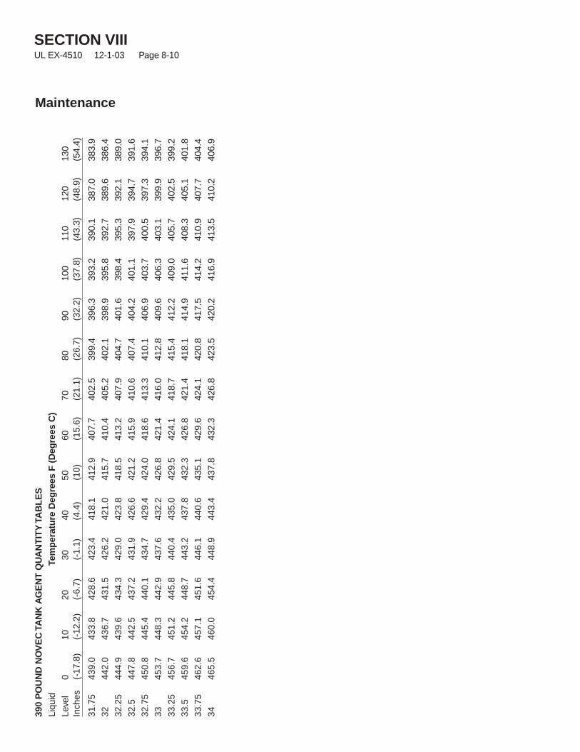
SECTION VIIIUL EX-4510 12-1-03 Page 8-10
Maintenance
390
PO
UN
DN
OV
EC
TAN
KA
GE
NT
QU
AN
TIT
YTA
BL
ES
Liqu
idTe
mp
erat
ure
Deg
rees
F(D
egre
esC
)Le
vel
010
2030
4050
6070
8090
100
110
120
130
Inch
es(-
17.8
)(-
12.2
)(-
6.7)
(-1.
1)(4
.4)
(10)
(15.
6)(2
1.1)
(26.
7)(3
2.2)
(37.
8)(4
3.3)
(48.
9)(5
4.4)
31.7
543
9.0
433.
842
8.6
423.
441
8.1
412.
940
7.7
402.
539
9.4
396.
339
3.2
390.
138
7.0
383.
9
3244
2.0
436.
743
1.5
426.
242
1.0
415.
741
0.4
405.
240
2.1
398.
939
5.8
392.
738
9.6
386.
4
32.2
544
4.9
439.
643
4.3
429.
042
3.8
418.
541
3.2
407.
940
4.7
401.
639
8.4
395.
339
2.1
389.
0
32.5
447.
844
2.5
437.
243
1.9
426.
642
1.2
415.
941
0.6
407.
440
4.2
401.
139
7.9
394.
739
1.6
32.7
545
0.8
445.
444
0.1
434.
742
9.4
424.
041
8.6
413.
341
0.1
406.
940
3.7
400.
539
7.3
394.
1
3345
3.7
448.
344
2.9
437.
643
2.2
426.
842
1.4
416.
041
2.8
409.
640
6.3
403.
139
9.9
396.
7
33.2
545
6.7
451.
244
5.8
440.
443
5.0
429.
542
4.1
418.
741
5.4
412.
240
9.0
405.
740
2.5
399.
2
33.5
459.
645
4.2
448.
744
3.2
437.
843
2.3
426.
842
1.4
418.
141
4.9
411.
640
8.3
405.
140
1.8
33.7
546
2.6
457.
145
1.6
446.
144
0.6
435.
142
9.6
424.
142
0.8
417.
541
4.2
410.
940
7.7
404.
4
3446
5.5
460.
045
4.4
448.
944
3.4
437.
843
2.3
426.
842
3.5
420.
241
6.9
413.
541
0.2
406.
9
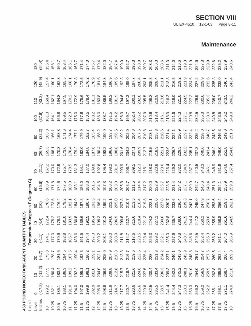
SECTION VIIIUL EX-4510 12-1-03 Page 8-11
Maintenance
450
PO
UN
DN
OV
EC
TAN
KA
GE
NT
QU
AN
TIT
YTA
BL
ES
Liqu
idTe
mp
erat
ure
Deg
rees
F(D
egre
esC
)Le
vel
010
2030
4050
6070
8090
100
110
120
130
Inch
es(-
17.8
)(-
12.2
)(-
6.7)
(-1.
1)(4
.4)
(10)
(15.
6)(2
1.1)
(26.
7)(3
2.2)
(37.
8)(4
3.3)
(48.
9)(5
4.4)
1017
9.2
177.
517
5.8
174.
117
2.4
170.
616
8.9
167.
216
5.3
163.
316
1.3
159.
415
7.4
155.
4
10.2
518
2.1
180.
417
8.7
177.
017
5.2
173.
517
1.8
170.
016
8.1
166.
116
4.1
162.
116
0.1
158.
1
10.5
185.
118
3.4
181.
617
9.9
178.
117
6.4
174.
617
2.9
170.
816
8.8
166.
816
4.8
162.
816
0.7
10.7
518
8.1
186.
318
4.5
182.
818
1.0
179.
217
7.5
175.
717
3.6
171.
616
9.5
167.
516
5.5
163.
4
1119
1.0
189.
218
7.5
185.
718
3.9
182.
118
0.3
178.
517
6.4
174.
417
2.3
170.
216
8.1
166.
1
11.2
519
4.0
192.
219
0.4
188.
618
6.8
184.
918
3.1
181.
317
9.2
177.
117
5.0
172.
917
0.8
168.
7
11.5
197.
019
5.1
193.
319
1.5
189.
618
7.8
186.
018
4.1
182.
017
9.9
177.
817
5.6
173.
517
1.4
11.7
519
9.9
198.
119
6.2
194.
419
2.5
190.
718
8.8
187.
018
4.8
182.
718
0.5
178.
417
6.2
174.
0
1220
2.9
201.
019
9.1
197.
319
5.4
193.
519
1.6
189.
818
7.6
185.
418
3.2
181.
117
8.9
176.
7
12.2
520
5.9
204.
020
2.1
200.
219
8.3
196.
419
4.5
192.
619
0.4
188.
218
6.0
183.
818
1.6
179.
4
12.5
208.
820
6.9
205.
020
3.1
201.
219
9.2
197.
319
5.4
193.
219
0.9
188.
718
6.5
184.
318
2.0
12.7
521
1.8
209.
820
7.9
206.
020
4.0
202.
120
0.2
198.
219
6.0
193.
719
1.5
189.
218
6.9
184.
7
1321
4.7
212.
821
0.8
208.
920
6.9
205.
020
3.0
201.
019
8.8
196.
519
4.2
191.
918
9.6
187.
4
13.2
521
7.7
215.
721
3.8
211.
820
9.8
207.
820
5.8
203.
920
1.6
199.
219
6.9
194.
619
2.3
190.
0
13.5
220.
721
8.7
216.
721
4.7
212.
721
0.7
208.
720
6.7
204.
320
2.0
199.
719
7.3
195.
019
2.7
13.7
522
3.6
221.
621
9.6
217.
621
5.6
213.
521
1.5
209.
520
7.1
204.
820
2.4
200.
119
7.7
195.
3
1422
6.6
224.
622
2.5
220.
521
8.4
216.
421
4.4
212.
320
9.9
207.
520
5.2
202.
820
0.4
198.
0
14.2
522
9.6
227.
522
5.4
223.
422
1.3
219.
321
7.2
215.
121
2.7
210.
320
7.9
205.
520
3.1
200.
7
14.5
232.
523
0.4
228.
422
6.3
224.
222
2.1
220.
021
8.0
215.
521
3.1
210.
620
8.2
205.
820
3.3
14.7
523
5.5
233.
423
1.3
229.
222
7.1
225.
022
2.9
220.
821
8.3
215.
821
3.4
210.
920
8.4
206.
0
1523
8.5
236.
323
4.2
232.
123
0.0
227.
822
5.7
223.
622
1.1
218.
621
6.1
213.
621
1.1
208.
6
15.2
524
1.4
239.
323
7.1
235.
023
2.8
230.
722
8.5
226.
422
3.9
221.
421
8.9
216.
321
3.8
211.
3
15.5
244.
424
2.2
240.
123
7.9
235.
723
3.6
231.
422
9.2
226.
722
4.1
221.
621
9.0
216.
521
4.0
15.7
524
7.3
245.
224
3.0
240.
823
8.6
236.
423
4.2
232.
022
9.5
226.
922
4.3
221.
821
9.2
216.
6
1625
0.3
248.
124
5.9
243.
724
1.5
239.
323
7.1
234.
923
2.3
229.
722
7.1
224.
522
1.9
219.
3
16.2
525
3.3
251.
024
8.8
246.
624
4.4
242.
123
9.9
237.
723
5.1
232.
422
9.8
227.
222
4.6
221.
9
16.5
256.
225
4.0
251.
724
9.5
247.
224
5.0
242.
724
0.5
237.
823
5.2
232.
522
9.9
227.
222
4.6
16.7
525
9.2
256.
925
4.7
252.
425
0.1
247.
924
5.6
243.
324
0.6
238.
023
5.3
232.
622
9.9
227.
3
1726
2.2
259.
925
7.6
255.
325
3.0
250.
724
8.4
246.
124
3.4
240.
723
8.0
235.
323
2.6
229.
9
17.2
526
5.1
262.
826
0.5
258.
225
5.9
253.
625
1.3
248.
924
6.2
243.
524
0.8
238.
023
5.3
232.
6
17.5
268.
126
5.8
263.
426
1.1
258.
825
6.4
254.
125
1.8
249.
024
6.3
243.
524
0.7
238.
023
5.2
17.7
527
1.1
268.
726
6.4
264.
026
1.6
259.
325
6.9
254.
625
1.8
249.
024
6.2
243.
524
0.7
237.
9
1827
4.0
271.
626
9.3
266.
926
4.5
262.
125
9.8
257.
425
4.6
251.
824
9.0
246.
224
3.4
240.
6
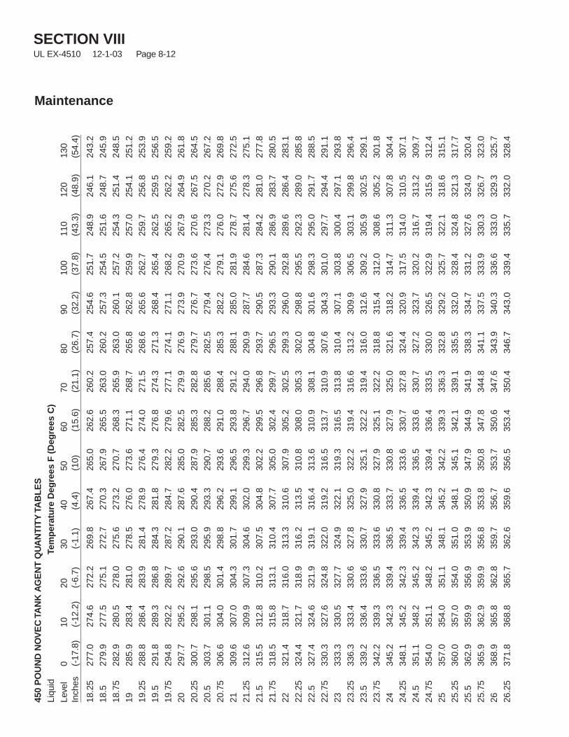
SECTION VIIIUL EX-4510 12-1-03 Page 8-12
Maintenance
450
PO
UN
DN
OV
EC
TAN
KA
GE
NT
QU
AN
TIT
YTA
BL
ES
Liqu
idTe
mp
erat
ure
Deg
rees
F(D
egre
esC
)Le
vel
010
2030
4050
6070
8090
100
110
120
130
Inch
es(-
17.8
)(-
12.2
)(-
6.7)
(-1.
1)(4
.4)
(10)
(15.
6)(2
1.1)
(26.
7)(3
2.2)
(37.
8)(4
3.3)
(48.
9)(5
4.4)
18.2
527
7.0
274.
627
2.2
269.
826
7.4
265.
026
2.6
260.
225
7.4
254.
625
1.7
248.
924
6.1
243.
2
18.5
279.
927
7.5
275.
127
2.7
270.
326
7.9
265.
526
3.0
260.
225
7.3
254.
525
1.6
248.
724
5.9
18.7
528
2.9
280.
527
8.0
275.
627
3.2
270.
726
8.3
265.
926
3.0
260.
125
7.2
254.
325
1.4
248.
5
1928
5.9
283.
428
1.0
278.
527
6.0
273.
627
1.1
268.
726
5.8
262.
825
9.9
257.
025
4.1
251.
2
19.2
528
8.8
286.
428
3.9
281.
427
8.9
276.
427
4.0
271.
526
8.6
265.
626
2.7
259.
725
6.8
253.
9
19.5
291.
828
9.3
286.
828
4.3
281.
827
9.3
276.
827
4.3
271.
326
8.4
265.
426
2.5
259.
525
6.5
19.7
529
4.8
292.
228
9.7
287.
228
4.7
282.
227
9.6
277.
127
4.1
271.
126
8.2
265.
226
2.2
259.
2
2029
7.7
295.
229
2.6
290.
128
7.6
285.
028
2.5
279.
927
6.9
273.
927
0.9
267.
926
4.9
261.
8
20.2
530
0.7
298.
129
5.6
293.
029
0.4
287.
928
5.3
282.
827
9.7
276.
727
3.6
270.
626
7.5
264.
5
20.5
303.
730
1.1
298.
529
5.9
293.
329
0.7
288.
228
5.6
282.
527
9.4
276.
427
3.3
270.
226
7.2
20.7
530
6.6
304.
030
1.4
298.
829
6.2
293.
629
1.0
288.
428
5.3
282.
227
9.1
276.
027
2.9
269.
8
2130
9.6
307.
030
4.3
301.
729
9.1
296.
529
3.8
291.
228
8.1
285.
028
1.9
278.
727
5.6
272.
5
21.2
531
2.6
309.
930
7.3
304.
630
2.0
299.
329
6.7
294.
029
0.9
287.
728
4.6
281.
427
8.3
275.
1
21.5
315.
531
2.8
310.
230
7.5
304.
830
2.2
299.
529
6.8
293.
729
0.5
287.
328
4.2
281.
027
7.8
21.7
531
8.5
315.
831
3.1
310.
430
7.7
305.
030
2.4
299.
729
6.5
293.
329
0.1
286.
928
3.7
280.
5
2232
1.4
318.
731
6.0
313.
331
0.6
307.
930
5.2
302.
529
9.3
296.
029
2.8
289.
628
6.4
283.
1
22.2
532
4.4
321.
731
8.9
316.
231
3.5
310.
830
8.0
305.
330
2.0
298.
829
5.5
292.
328
9.0
285.
8
22.5
327.
432
4.6
321.
931
9.1
316.
431
3.6
310.
930
8.1
304.
830
1.6
298.
329
5.0
291.
728
8.5
22.7
533
0.3
327.
632
4.8
322.
031
9.2
316.
531
3.7
310.
930
7.6
304.
330
1.0
297.
729
4.4
291.
1
2333
3.3
330.
532
7.7
324.
932
2.1
319.
331
6.5
313.
831
0.4
307.
130
3.8
300.
429
7.1
293.
8
23.2
533
6.3
333.
433
0.6
327.
832
5.0
322.
231
9.4
316.
631
3.2
309.
930
6.5
303.
129
9.8
296.
4
23.5
339.
233
6.4
333.
633
0.7
327.
932
5.1
322.
231
9.4
316.
031
2.6
309.
230
5.9
302.
529
9.1
23.7
534
2.2
339.
333
6.5
333.
633
0.8
327.
932
5.1
322.
231
8.8
315.
431
2.0
308.
630
5.2
301.
8
2434
5.2
342.
333
9.4
336.
533
3.7
330.
832
7.9
325.
032
1.6
318.
231
4.7
311.
330
7.8
304.
4
24.2
534
8.1
345.
234
2.3
339.
433
6.5
333.
633
0.7
327.
832
4.4
320.
931
7.5
314.
031
0.5
307.
1
24.5
351.
134
8.2
345.
234
2.3
339.
433
6.5
333.
633
0.7
327.
232
3.7
320.
231
6.7
313.
230
9.7
24.7
535
4.0
351.
134
8.2
345.
234
2.3
339.
433
6.4
333.
533
0.0
326.
532
2.9
319.
431
5.9
312.
4
2535
7.0
354.
035
1.1
348.
134
5.2
342.
233
9.3
336.
333
2.8
329.
232
5.7
322.
131
8.6
315.
1
25.2
536
0.0
357.
035
4.0
351.
034
8.1
345.
134
2.1
339.
133
5.5
332.
032
8.4
324.
832
1.3
317.
7
25.5
362.
935
9.9
356.
935
3.9
350.
934
7.9
344.
934
1.9
338.
333
4.7
331.
232
7.6
324.
032
0.4
25.7
536
5.9
362.
935
9.9
356.
835
3.8
350.
834
7.8
344.
834
1.1
337.
533
3.9
330.
332
6.7
323.
0
2636
8.9
365.
836
2.8
359.
735
6.7
353.
735
0.6
347.
634
3.9
340.
333
6.6
333.
032
9.3
325.
7
26.2
537
1.8
368.
836
5.7
362.
635
9.6
356.
535
3.4
350.
434
6.7
343.
033
9.4
335.
733
2.0
328.
4
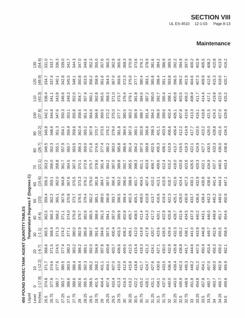
SECTION VIIIUL EX-4510 12-1-03 Page 8-13
Maintenance
450
PO
UN
DN
OV
EC
TAN
KA
GE
NT
QU
AN
TIT
YTA
BL
ES
Liqu
idTe
mp
erat
ure
Deg
rees
F(D
egre
esC
)Le
vel
010
2030
4050
6070
8090
100
110
120
130
Inch
es(-
17.8
)(-
12.2
)(-
6.7)
(-1.
1)(4
.4)
(10)
(15.
6)(2
1.1)
(26.
7)(3
2.2)
(37.
8)(4
3.3)
(48.
9)(5
4.4)
26.5
374.
837
1.7
368.
636
5.5
362.
535
9.4
356.
335
3.2
349.
534
5.8
342.
133
8.4
334.
733
1.0
26.7
537
7.8
374.
637
1.5
368.
436
5.3
362.
235
9.1
356.
035
2.3
348.
634
4.8
341.
133
7.4
333.
7
2738
0.7
377.
637
4.5
371.
336
8.2
365.
136
2.0
358.
835
5.1
351.
334
7.6
343.
834
0.1
336.
3
27.2
538
3.7
380.
537
7.4
374.
237
1.1
367.
936
4.8
361.
735
7.9
354.
135
0.3
346.
634
2.8
339.
0
27.5
386.
638
3.5
380.
337
7.1
374.
037
0.8
367.
636
4.5
360.
735
6.9
353.
134
9.3
345.
534
1.7
27.7
538
9.6
386.
438
3.2
380.
037
6.9
373.
737
0.5
367.
336
3.5
359.
635
5.8
352.
034
8.1
344.
3
2839
2.6
389.
438
6.2
382.
937
9.7
376.
537
3.3
370.
136
6.3
362.
435
8.5
354.
735
0.8
347.
0
28.2
539
5.5
392.
338
9.1
385.
838
2.6
379.
437
6.2
372.
936
9.0
365.
236
1.3
357.
435
3.5
349.
6
28.5
398.
539
5.2
392.
038
8.7
385.
538
2.2
379.
037
5.7
371.
836
7.9
364.
036
0.1
356.
235
2.3
28.7
540
1.5
398.
239
4.9
391.
638
8.4
385.
138
1.8
378.
637
4.6
370.
736
6.8
362.
835
8.9
355.
0
2940
4.4
401.
139
7.8
394.
639
1.3
388.
038
4.7
381.
437
7.4
373.
536
9.5
365.
536
1.6
357.
6
29.2
540
7.4
404.
140
0.8
397.
539
4.1
390.
838
7.5
384.
238
0.2
376.
237
2.2
368.
336
4.3
360.
3
29.5
410.
440
7.0
403.
740
0.4
397.
039
3.7
390.
438
7.0
383.
037
9.0
375.
037
1.0
367.
036
2.9
29.7
541
3.3
410.
040
6.6
403.
339
9.9
396.
539
3.2
389.
838
5.8
381.
837
7.7
373.
736
9.6
365.
6
3041
6.3
412.
940
9.5
406.
240
2.8
399.
439
6.0
392.
738
8.6
384.
538
0.5
376.
437
2.3
368.
3
30.2
541
9.2
415.
841
2.5
409.
140
5.7
402.
339
8.9
395.
539
1.4
387.
338
3.2
379.
137
5.0
370.
9
30.5
422.
241
8.8
415.
441
2.0
408.
540
5.1
401.
739
8.3
394.
239
0.1
385.
938
1.8
377.
737
3.6
30.7
542
5.2
421.
741
8.3
414.
941
1.4
408.
040
4.5
401.
139
7.0
392.
838
8.7
384.
538
0.4
376.
2
3142
8.1
424.
742
1.2
417.
841
4.3
410.
840
7.4
403.
939
9.8
395.
639
1.4
387.
238
3.1
378.
9
31.2
543
1.1
427.
642
4.1
420.
741
7.2
413.
741
0.2
406.
740
2.5
398.
339
4.2
390.
038
5.8
381.
6
31.5
434.
143
0.6
427.
142
3.6
420.
141
6.6
413.
140
9.6
405.
340
1.1
396.
939
2.7
388.
438
4.2
31.7
543
7.0
433.
543
0.0
426.
542
2.9
419.
441
5.9
412.
440
8.1
403.
939
9.6
395.
439
1.1
386.
9
3244
0.0
436.
443
2.9
429.
442
5.8
422.
341
8.7
415.
241
0.9
406.
640
2.4
398.
139
3.8
389.
5
32.2
544
3.0
439.
443
5.8
432.
342
8.7
425.
142
1.6
418.
041
3.7
409.
440
5.1
400.
839
6.5
392.
2
32.5
445.
944
2.3
438.
843
5.2
431.
642
8.0
424.
442
0.8
416.
541
2.2
407.
840
3.5
399.
239
4.9
32.7
544
8.9
445.
344
1.7
438.
143
4.5
430.
942
7.3
423.
641
9.3
414.
941
0.6
406.
240
1.9
397.
5
3345
1.8
448.
244
4.6
441.
043
7.3
433.
743
0.1
426.
542
2.1
417.
741
3.3
408.
940
4.6
400.
2
33.2
545
4.8
451.
244
7.5
443.
944
0.2
436.
643
2.9
429.
342
4.9
420.
541
6.1
411.
740
7.3
402.
9
33.5
457.
845
4.1
450.
444
6.8
443.
143
9.4
435.
843
2.1
427.
742
3.2
418.
841
4.4
409.
940
5.5
33.7
546
0.7
457.
045
3.4
449.
744
6.0
442.
343
8.6
434.
943
0.5
426.
042
1.5
417.
141
2.6
408.
2
3446
3.7
460.
045
6.3
452.
644
8.9
445.
244
1.4
437.
743
3.3
428.
842
4.3
419.
841
5.3
410.
8
34.2
546
6.7
462.
945
9.2
455.
545
1.7
448.
044
4.3
440.
643
6.0
431.
542
7.0
422.
541
8.0
413.
5
34.5
469.
646
5.9
462.
145
8.4
454.
645
0.9
447.
144
3.4
438.
843
4.3
429.
842
5.2
420.
741
6.2
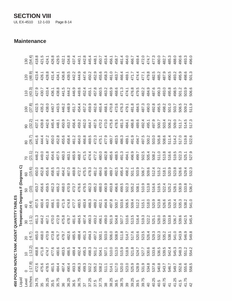
SECTION VIIIUL EX-4510 12-1-03 Page 8-14
Maintenance
450
PO
UN
DN
OV
EC
TAN
KA
GE
NT
QU
AN
TIT
YTA
BL
ES
Liqu
idTe
mp
erat
ure
Deg
rees
F(D
egre
esC
)Le
vel
010
2030
4050
6070
8090
100
110
120
130
Inch
es(-
17.8
)(-
12.2
)(-
6.7)
(-1.
1)(4
.4)
(10)
(15.
6)(2
1.1)
(26.
7)(3
2.2)
(37.
8)(4
3.3)
(48.
9)(5
4.4)
34.7
547
2.6
468.
846
5.0
461.
345
7.5
453.
745
0.0
446.
244
1.6
437.
143
2.5
427.
942
3.4
418.
8
3547
5.6
471.
846
8.0
464.
246
0.4
456.
645
2.8
449.
044
4.4
439.
843
5.2
430.
742
6.1
421.
5
35.2
547
8.5
474.
747
0.9
467.
146
3.3
459.
545
5.6
451.
844
7.2
442.
643
8.0
433.
442
8.8
424.
1
35.5
481.
547
7.6
473.
847
0.0
466.
146
2.3
458.
545
4.6
450.
044
5.4
440.
743
6.1
431.
442
6.8
35.7
548
4.4
480.
647
6.7
472.
946
9.0
465.
246
1.3
457.
545
2.8
448.
144
3.5
438.
843
4.1
429.
5
3648
7.4
483.
547
9.7
475.
847
1.9
468.
046
4.2
460.
345
5.6
450.
944
6.2
441.
543
6.8
432.
1
36.2
549
0.4
486.
548
2.6
478.
747
4.8
470.
946
7.0
463.
145
8.4
453.
744
8.9
444.
243
9.5
434.
8
36.5
493.
348
9.4
485.
548
1.6
477.
747
3.7
469.
846
5.9
461.
245
6.4
451.
744
6.9
442.
243
7.4
36.7
549
6.3
492.
448
8.4
484.
548
0.5
476.
647
2.7
468.
746
4.0
459.
245
4.4
449.
644
4.9
440.
1
3749
9.3
495.
349
1.3
487.
448
3.4
479.
547
5.5
471.
546
6.8
462.
045
7.2
452.
444
7.6
442.
8
37.2
550
2.2
498.
349
4.3
490.
348
6.3
482.
347
8.3
474.
446
9.5
464.
745
9.9
455.
145
0.2
445.
4
37.5
505.
250
1.2
497.
249
3.2
489.
248
5.2
481.
247
7.2
472.
346
7.5
462.
645
7.8
452.
944
8.1
37.7
550
8.2
504.
150
0.1
496.
149
2.1
488.
048
4.0
480.
047
5.1
470.
246
5.4
460.
545
5.6
450.
7
3851
1.1
507.
150
3.0
499.
049
4.9
490.
948
6.9
482.
847
7.9
473.
046
8.1
463.
245
8.3
453.
4
38.2
551
4.1
510.
050
6.0
501.
949
7.8
493.
848
9.7
485.
648
0.7
475.
847
0.8
465.
946
1.0
456.
1
38.5
517.
051
3.0
508.
950
4.8
500.
749
6.6
492.
548
8.5
483.
547
8.5
473.
646
8.6
463.
745
8.7
38.7
552
0.0
515.
951
1.8
507.
750
3.6
499.
549
5.4
491.
348
6.3
481.
347
6.3
471.
346
6.4
461.
4
3952
3.0
518.
951
4.7
510.
650
6.5
502.
349
8.2
494.
148
9.1
484.
147
9.1
474.
146
9.1
464.
0
39.2
552
5.9
521.
851
7.6
513.
550
9.4
505.
250
1.1
496.
949
1.9
486.
848
1.8
476.
847
1.7
466.
7
39.5
528.
952
4.7
520.
651
6.4
512.
250
8.1
503.
949
9.7
494.
748
9.6
484.
547
9.5
474.
446
9.4
39.7
553
1.9
527.
752
3.5
519.
351
5.1
510.
950
6.7
502.
549
7.5
492.
448
7.3
482.
247
7.1
472.
0
4053
4.8
530.
652
6.4
522.
251
8.0
513.
850
9.6
505.
450
0.2
495.
149
0.0
484.
947
9.8
474.
7
40.2
553
7.8
533.
652
9.3
525.
152
0.9
516.
651
2.4
508.
250
3.0
497.
949
2.8
487.
648
2.5
477.
3
40.5
540.
853
6.5
532.
352
8.0
523.
851
9.5
515.
251
1.0
505.
850
0.7
495.
549
0.3
485.
248
0.0
40.7
554
3.7
539.
553
5.2
530.
952
6.6
522.
451
8.1
513.
850
8.6
503.
449
8.2
493.
048
7.9
482.
7
4154
6.7
542.
453
8.1
533.
852
9.5
525.
252
0.9
516.
651
1.4
506.
250
1.0
495.
849
0.5
485.
3
41.2
554
9.7
545.
354
1.0
536.
753
2.4
528.
152
3.8
519.
551
4.2
509.
050
3.7
498.
549
3.2
488.
0
41.5
552.
654
8.3
543.
953
9.6
535.
353
0.9
526.
652
2.3
517.
051
1.7
506.
550
1.2
495.
949
0.6
41.7
555
5.6
551.
254
6.9
542.
553
8.2
533.
852
9.4
525.
151
9.8
514.
550
9.2
503.
949
8.6
493.
3
4255
8.5
554.
254
9.8
545.
454
1.0
536.
753
2.3
527.
952
2.6
517.
351
1.9
506.
650
1.3
496.
0
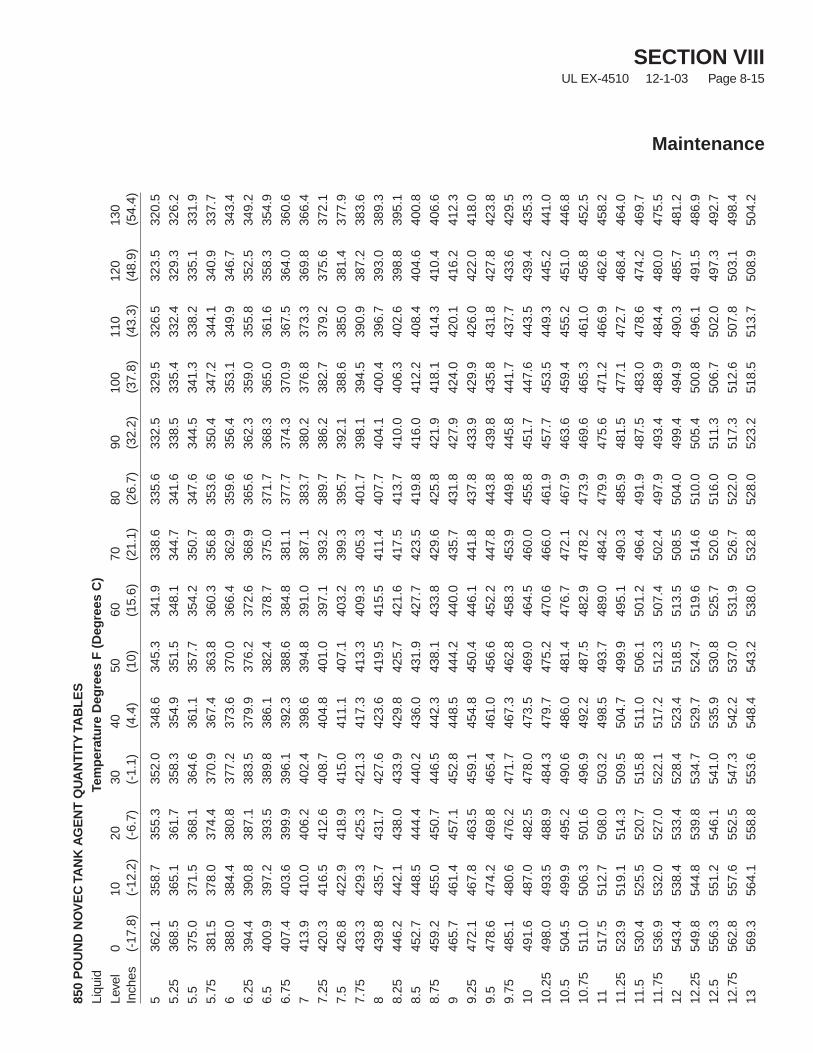
SECTION VIIIUL EX-4510 12-1-03 Page 8-15
Maintenance
850
PO
UN
DN
OV
EC
TAN
KA
GE
NT
QU
AN
TIT
YTA
BL
ES
Liqu
idTe
mp
erat
ure
Deg
rees
F(D
egre
esC
)Le
vel
010
2030
4050
6070
8090
100
110
120
130
Inch
es(-
17.8
)(-
12.2
)(-
6.7)
(-1.
1)(4
.4)
(10)
(15.
6)(2
1.1)
(26.
7)(3
2.2)
(37.
8)(4
3.3)
(48.
9)(5
4.4)
536
2.1
358.
735
5.3
352.
034
8.6
345.
334
1.9
338.
633
5.6
332.
532
9.5
326.
532
3.5
320.
5
5.25
368.
536
5.1
361.
735
8.3
354.
935
1.5
348.
134
4.7
341.
633
8.5
335.
433
2.4
329.
332
6.2
5.5
375.
037
1.5
368.
136
4.6
361.
135
7.7
354.
235
0.7
347.
634
4.5
341.
333
8.2
335.
133
1.9
5.75
381.
537
8.0
374.
437
0.9
367.
436
3.8
360.
335
6.8
353.
635
0.4
347.
234
4.1
340.
933
7.7
638
8.0
384.
438
0.8
377.
237
3.6
370.
036
6.4
362.
935
9.6
356.
435
3.1
349.
934
6.7
343.
4
6.25
394.
439
0.8
387.
138
3.5
379.
937
6.2
372.
636
8.9
365.
636
2.3
359.
035
5.8
352.
534
9.2
6.5
400.
939
7.2
393.
538
9.8
386.
138
2.4
378.
737
5.0
371.
736
8.3
365.
036
1.6
358.
335
4.9
6.75
407.
440
3.6
399.
939
6.1
392.
338
8.6
384.
838
1.1
377.
737
4.3
370.
936
7.5
364.
036
0.6
741
3.9
410.
040
6.2
402.
439
8.6
394.
839
1.0
387.
138
3.7
380.
237
6.8
373.
336
9.8
366.
4
7.25
420.
341
6.5
412.
640
8.7
404.
840
1.0
397.
139
3.2
389.
738
6.2
382.
737
9.2
375.
637
2.1
7.5
426.
842
2.9
418.
941
5.0
411.
140
7.1
403.
239
9.3
395.
739
2.1
388.
638
5.0
381.
437
7.9
7.75
433.
342
9.3
425.
342
1.3
417.
341
3.3
409.
340
5.3
401.
739
8.1
394.
539
0.9
387.
238
3.6
843
9.8
435.
743
1.7
427.
642
3.6
419.
541
5.5
411.
440
7.7
404.
140
0.4
396.
739
3.0
389.
3
8.25
446.
244
2.1
438.
043
3.9
429.
842
5.7
421.
641
7.5
413.
741
0.0
406.
340
2.6
398.
839
5.1
8.5
452.
744
8.5
444.
444
0.2
436.
043
1.9
427.
742
3.5
419.
841
6.0
412.
240
8.4
404.
640
0.8
8.75
459.
245
5.0
450.
744
6.5
442.
343
8.1
433.
842
9.6
425.
842
1.9
418.
141
4.3
410.
440
6.6
946
5.7
461.
445
7.1
452.
844
8.5
444.
244
0.0
435.
743
1.8
427.
942
4.0
420.
141
6.2
412.
3
9.25
472.
146
7.8
463.
545
9.1
454.
845
0.4
446.
144
1.8
437.
843
3.9
429.
942
6.0
422.
041
8.0
9.5
478.
647
4.2
469.
846
5.4
461.
045
6.6
452.
244
7.8
443.
843
9.8
435.
843
1.8
427.
842
3.8
9.75
485.
148
0.6
476.
247
1.7
467.
346
2.8
458.
345
3.9
449.
844
5.8
441.
743
7.7
433.
642
9.5
1049
1.6
487.
048
2.5
478.
047
3.5
469.
046
4.5
460.
045
5.8
451.
744
7.6
443.
543
9.4
435.
3
10.2
549
8.0
493.
548
8.9
484.
347
9.7
475.
247
0.6
466.
046
1.9
457.
745
3.5
449.
344
5.2
441.
0
10.5
504.
549
9.9
495.
249
0.6
486.
048
1.4
476.
747
2.1
467.
946
3.6
459.
445
5.2
451.
044
6.8
10.7
551
1.0
506.
350
1.6
496.
949
2.2
487.
548
2.9
478.
247
3.9
469.
646
5.3
461.
045
6.8
452.
5
1151
7.5
512.
750
8.0
503.
249
8.5
493.
748
9.0
484.
247
9.9
475.
647
1.2
466.
946
2.6
458.
2
11.2
552
3.9
519.
151
4.3
509.
550
4.7
499.
949
5.1
490.
348
5.9
481.
547
7.1
472.
746
8.4
464.
0
11.5
530.
452
5.5
520.
751
5.8
511.
050
6.1
501.
249
6.4
491.
948
7.5
483.
047
8.6
474.
246
9.7
11.7
553
6.9
532.
052
7.0
522.
151
7.2
512.
350
7.4
502.
449
7.9
493.
448
8.9
484.
448
0.0
475.
5
1254
3.4
538.
453
3.4
528.
452
3.4
518.
551
3.5
508.
550
4.0
499.
449
4.9
490.
348
5.7
481.
2
12.2
554
9.8
544.
853
9.8
534.
752
9.7
524.
751
9.6
514.
651
0.0
505.
450
0.8
496.
149
1.5
486.
9
12.5
556.
355
1.2
546.
154
1.0
535.
953
0.8
525.
752
0.6
516.
051
1.3
506.
750
2.0
497.
349
2.7
12.7
556
2.8
557.
655
2.5
547.
354
2.2
537.
053
1.9
526.
752
2.0
517.
351
2.6
507.
850
3.1
498.
4
1356
9.3
564.
155
8.8
553.
654
8.4
543.
253
8.0
532.
852
8.0
523.
251
8.5
513.
750
8.9
504.
2
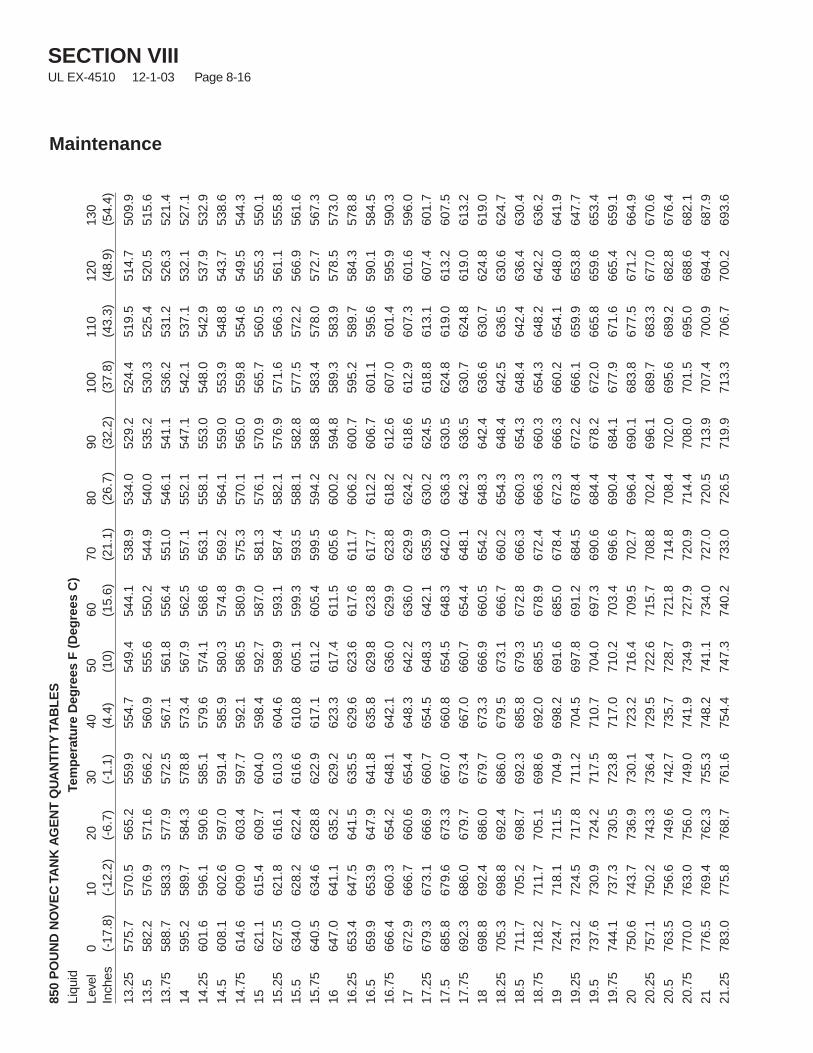
SECTION VIIIUL EX-4510 12-1-03 Page 8-16
Maintenance
850
PO
UN
DN
OV
EC
TAN
KA
GE
NT
QU
AN
TIT
YTA
BL
ES
Liqu
idTe
mp
erat
ure
Deg
rees
F(D
egre
esC
)Le
vel
010
2030
4050
6070
8090
100
110
120
130
Inch
es(-
17.8
)(-
12.2
)(-
6.7)
(-1.
1)(4
.4)
(10)
(15.
6)(2
1.1)
(26.
7)(3
2.2)
(37.
8)(4
3.3)
(48.
9)(5
4.4)
13.2
557
5.7
570.
556
5.2
559.
955
4.7
549.
454
4.1
538.
953
4.0
529.
252
4.4
519.
551
4.7
509.
9
13.5
582.
257
6.9
571.
656
6.2
560.
955
5.6
550.
254
4.9
540.
053
5.2
530.
352
5.4
520.
551
5.6
13.7
558
8.7
583.
357
7.9
572.
556
7.1
561.
855
6.4
551.
054
6.1
541.
153
6.2
531.
252
6.3
521.
4
1459
5.2
589.
758
4.3
578.
857
3.4
567.
956
2.5
557.
155
2.1
547.
154
2.1
537.
153
2.1
527.
1
14.2
560
1.6
596.
159
0.6
585.
157
9.6
574.
156
8.6
563.
155
8.1
553.
054
8.0
542.
953
7.9
532.
9
14.5
608.
160
2.6
597.
059
1.4
585.
958
0.3
574.
856
9.2
564.
155
9.0
553.
954
8.8
543.
753
8.6
14.7
561
4.6
609.
060
3.4
597.
759
2.1
586.
558
0.9
575.
357
0.1
565.
055
9.8
554.
654
9.5
544.
3
1562
1.1
615.
460
9.7
604.
059
8.4
592.
758
7.0
581.
357
6.1
570.
956
5.7
560.
555
5.3
550.
1
15.2
562
7.5
621.
861
6.1
610.
360
4.6
598.
959
3.1
587.
458
2.1
576.
957
1.6
566.
356
1.1
555.
8
15.5
634.
062
8.2
622.
461
6.6
610.
860
5.1
599.
359
3.5
588.
158
2.8
577.
557
2.2
566.
956
1.6
15.7
564
0.5
634.
662
8.8
622.
961
7.1
611.
260
5.4
599.
559
4.2
588.
858
3.4
578.
057
2.7
567.
3
1664
7.0
641.
163
5.2
629.
262
3.3
617.
461
1.5
605.
660
0.2
594.
858
9.3
583.
957
8.5
573.
0
16.2
565
3.4
647.
564
1.5
635.
562
9.6
623.
661
7.6
611.
760
6.2
600.
759
5.2
589.
758
4.3
578.
8
16.5
659.
965
3.9
647.
964
1.8
635.
862
9.8
623.
861
7.7
612.
260
6.7
601.
159
5.6
590.
158
4.5
16.7
566
6.4
660.
365
4.2
648.
164
2.1
636.
062
9.9
623.
861
8.2
612.
660
7.0
601.
459
5.9
590.
3
1767
2.9
666.
766
0.6
654.
464
8.3
642.
263
6.0
629.
962
4.2
618.
661
2.9
607.
360
1.6
596.
0
17.2
567
9.3
673.
166
6.9
660.
765
4.5
648.
364
2.1
635.
963
0.2
624.
561
8.8
613.
160
7.4
601.
7
17.5
685.
867
9.6
673.
366
7.0
660.
865
4.5
648.
364
2.0
636.
363
0.5
624.
861
9.0
613.
260
7.5
17.7
569
2.3
686.
067
9.7
673.
466
7.0
660.
765
4.4
648.
164
2.3
636.
563
0.7
624.
861
9.0
613.
2
1869
8.8
692.
468
6.0
679.
767
3.3
666.
966
0.5
654.
264
8.3
642.
463
6.6
630.
762
4.8
619.
0
18.2
570
5.3
698.
869
2.4
686.
067
9.5
673.
166
6.7
660.
265
4.3
648.
464
2.5
636.
563
0.6
624.
7
18.5
711.
770
5.2
698.
769
2.3
685.
867
9.3
672.
866
6.3
660.
365
4.3
648.
464
2.4
636.
463
0.4
18.7
571
8.2
711.
770
5.1
698.
669
2.0
685.
567
8.9
672.
466
6.3
660.
365
4.3
648.
264
2.2
636.
2
1972
4.7
718.
171
1.5
704.
969
8.2
691.
668
5.0
678.
467
2.3
666.
366
0.2
654.
164
8.0
641.
9
19.2
573
1.2
724.
571
7.8
711.
270
4.5
697.
869
1.2
684.
567
8.4
672.
266
6.1
659.
965
3.8
647.
7
19.5
737.
673
0.9
724.
271
7.5
710.
770
4.0
697.
369
0.6
684.
467
8.2
672.
066
5.8
659.
665
3.4
19.7
574
4.1
737.
373
0.5
723.
871
7.0
710.
270
3.4
696.
669
0.4
684.
167
7.9
671.
666
5.4
659.
1
2075
0.6
743.
773
6.9
730.
172
3.2
716.
470
9.5
702.
769
6.4
690.
168
3.8
677.
567
1.2
664.
9
20.2
575
7.1
750.
274
3.3
736.
472
9.5
722.
671
5.7
708.
870
2.4
696.
168
9.7
683.
367
7.0
670.
6
20.5
763.
575
6.6
749.
674
2.7
735.
772
8.7
721.
871
4.8
708.
470
2.0
695.
668
9.2
682.
867
6.4
20.7
577
0.0
763.
075
6.0
749.
074
1.9
734.
972
7.9
720.
971
4.4
708.
070
1.5
695.
068
8.6
682.
1
2177
6.5
769.
476
2.3
755.
374
8.2
741.
173
4.0
727.
072
0.5
713.
970
7.4
700.
969
4.4
687.
9
21.2
578
3.0
775.
876
8.7
761.
675
4.4
747.
374
0.2
733.
072
6.5
719.
971
3.3
706.
770
0.2
693.
6
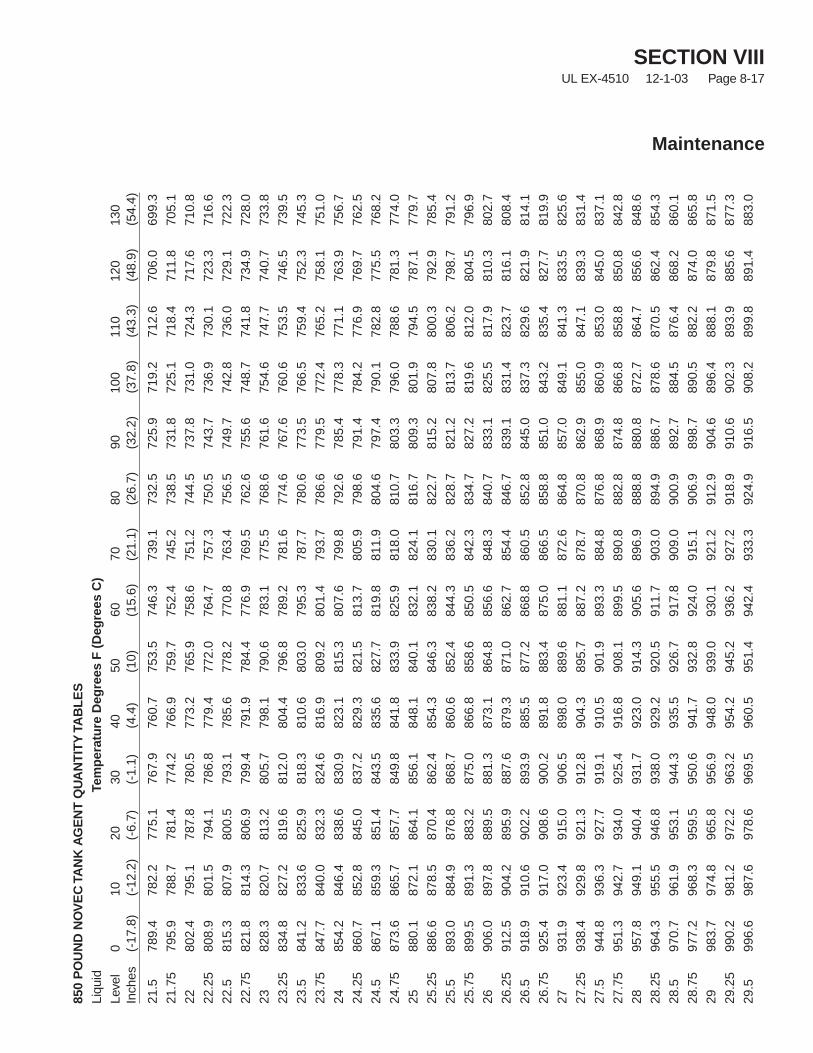
SECTION VIIIUL EX-4510 12-1-03 Page 8-17
Maintenance
850
PO
UN
DN
OV
EC
TAN
KA
GE
NT
QU
AN
TIT
YTA
BL
ES
Liqu
idTe
mp
erat
ure
Deg
rees
F(D
egre
esC
)Le
vel
010
2030
4050
6070
8090
100
110
120
130
Inch
es(-
17.8
)(-
12.2
)(-
6.7)
(-1.
1)(4
.4)
(10)
(15.
6)(2
1.1)
(26.
7)(3
2.2)
(37.
8)(4
3.3)
(48.
9)(5
4.4)
21.5
789.
478
2.2
775.
176
7.9
760.
775
3.5
746.
373
9.1
732.
572
5.9
719.
271
2.6
706.
069
9.3
21.7
579
5.9
788.
778
1.4
774.
276
6.9
759.
775
2.4
745.
273
8.5
731.
872
5.1
718.
471
1.8
705.
1
2280
2.4
795.
178
7.8
780.
577
3.2
765.
975
8.6
751.
274
4.5
737.
873
1.0
724.
371
7.6
710.
8
22.2
580
8.9
801.
579
4.1
786.
877
9.4
772.
076
4.7
757.
375
0.5
743.
773
6.9
730.
172
3.3
716.
6
22.5
815.
380
7.9
800.
579
3.1
785.
677
8.2
770.
876
3.4
756.
574
9.7
742.
873
6.0
729.
172
2.3
22.7
582
1.8
814.
380
6.9
799.
479
1.9
784.
477
6.9
769.
576
2.6
755.
674
8.7
741.
873
4.9
728.
0
2382
8.3
820.
781
3.2
805.
779
8.1
790.
678
3.1
775.
576
8.6
761.
675
4.6
747.
774
0.7
733.
8
23.2
583
4.8
827.
281
9.6
812.
080
4.4
796.
878
9.2
781.
677
4.6
767.
676
0.6
753.
574
6.5
739.
5
23.5
841.
283
3.6
825.
981
8.3
810.
680
3.0
795.
378
7.7
780.
677
3.5
766.
575
9.4
752.
374
5.3
23.7
584
7.7
840.
083
2.3
824.
681
6.9
809.
280
1.4
793.
778
6.6
779.
577
2.4
765.
275
8.1
751.
0
2485
4.2
846.
483
8.6
830.
982
3.1
815.
380
7.6
799.
879
2.6
785.
477
8.3
771.
176
3.9
756.
7
24.2
586
0.7
852.
884
5.0
837.
282
9.3
821.
581
3.7
805.
979
8.6
791.
478
4.2
776.
976
9.7
762.
5
24.5
867.
185
9.3
851.
484
3.5
835.
682
7.7
819.
881
1.9
804.
679
7.4
790.
178
2.8
775.
576
8.2
24.7
587
3.6
865.
785
7.7
849.
884
1.8
833.
982
5.9
818.
081
0.7
803.
379
6.0
788.
678
1.3
774.
0
2588
0.1
872.
186
4.1
856.
184
8.1
840.
183
2.1
824.
181
6.7
809.
380
1.9
794.
578
7.1
779.
7
25.2
588
6.6
878.
587
0.4
862.
485
4.3
846.
383
8.2
830.
182
2.7
815.
280
7.8
800.
379
2.9
785.
4
25.5
893.
088
4.9
876.
886
8.7
860.
685
2.4
844.
383
6.2
828.
782
1.2
813.
780
6.2
798.
779
1.2
25.7
589
9.5
891.
388
3.2
875.
086
6.8
858.
685
0.5
842.
383
4.7
827.
281
9.6
812.
080
4.5
796.
9
2690
6.0
897.
888
9.5
881.
387
3.1
864.
885
6.6
848.
384
0.7
833.
182
5.5
817.
981
0.3
802.
7
26.2
591
2.5
904.
289
5.9
887.
687
9.3
871.
086
2.7
854.
484
6.7
839.
183
1.4
823.
781
6.1
808.
4
26.5
918.
991
0.6
902.
289
3.9
885.
587
7.2
868.
886
0.5
852.
884
5.0
837.
382
9.6
821.
981
4.1
26.7
592
5.4
917.
090
8.6
900.
289
1.8
883.
487
5.0
866.
585
8.8
851.
084
3.2
835.
482
7.7
819.
9
2793
1.9
923.
491
5.0
906.
589
8.0
889.
688
1.1
872.
686
4.8
857.
084
9.1
841.
383
3.5
825.
6
27.2
593
8.4
929.
892
1.3
912.
890
4.3
895.
788
7.2
878.
787
0.8
862.
985
5.0
847.
183
9.3
831.
4
27.5
944.
893
6.3
927.
791
9.1
910.
590
1.9
893.
388
4.8
876.
886
8.9
860.
985
3.0
845.
083
7.1
27.7
595
1.3
942.
793
4.0
925.
491
6.8
908.
189
9.5
890.
888
2.8
874.
886
6.8
858.
885
0.8
842.
8
2895
7.8
949.
194
0.4
931.
792
3.0
914.
390
5.6
896.
988
8.8
880.
887
2.7
864.
785
6.6
848.
6
28.2
596
4.3
955.
594
6.8
938.
092
9.2
920.
591
1.7
903.
089
4.9
886.
787
8.6
870.
586
2.4
854.
3
28.5
970.
796
1.9
953.
194
4.3
935.
592
6.7
917.
890
9.0
900.
989
2.7
884.
587
6.4
868.
286
0.1
28.7
597
7.2
968.
395
9.5
950.
694
1.7
932.
892
4.0
915.
190
6.9
898.
789
0.5
882.
287
4.0
865.
8
2998
3.7
974.
896
5.8
956.
994
8.0
939.
093
0.1
921.
291
2.9
904.
689
6.4
888.
187
9.8
871.
5
29.2
599
0.2
981.
297
2.2
963.
295
4.2
945.
293
6.2
927.
291
8.9
910.
690
2.3
893.
988
5.6
877.
3
29.5
996.
698
7.6
978.
696
9.5
960.
595
1.4
942.
493
3.3
924.
991
6.5
908.
289
9.8
891.
488
3.0
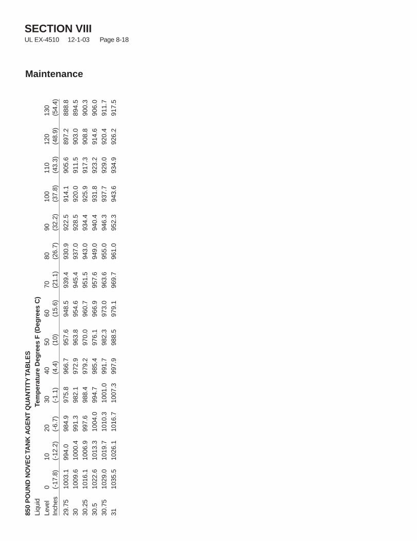
SECTION VIIIUL EX-4510 12-1-03 Page 8-18
Maintenance
850
PO
UN
DN
OV
EC
TAN
KA
GE
NT
QU
AN
TIT
YTA
BL
ES
Liqu
idTe
mp
erat
ure
Deg
rees
F(D
egre
esC
)Le
vel
010
2030
4050
6070
8090
100
110
120
130
Inch
es(-
17.8
)(-
12.2
)(-
6.7)
(-1.
1)(4
.4)
(10)
(15.
6)(2
1.1)
(26.
7)(3
2.2)
(37.
8)(4
3.3)
(48.
9)(5
4.4)
29.7
510
03.1
994.
098
4.9
975.
896
6.7
957.
694
8.5
939.
493
0.9
922.
591
4.1
905.
689
7.2
888.
8
3010
09.6
1000
.499
1.3
982.
197
2.9
963.
895
4.6
945.
493
7.0
928.
592
0.0
911.
590
3.0
894.
5
30.2
510
16.1
1006
.999
7.6
988.
497
9.2
970.
096
0.7
951.
594
3.0
934.
492
5.9
917.
390
8.8
900.
3
30.5
1022
.610
13.3
1004
.099
4.7
985.
497
6.1
966.
995
7.6
949.
094
0.4
931.
892
3.2
914.
690
6.0
30.7
510
29.0
1019
.710
10.3
1001
.099
1.7
982.
397
3.0
963.
695
5.0
946.
393
7.7
929.
092
0.4
911.
7
3110
35.5
1026
.110
16.7
1007
.399
7.9
988.
597
9.1
969.
796
1.0
952.
394
3.6
934.
992
6.2
917.
5
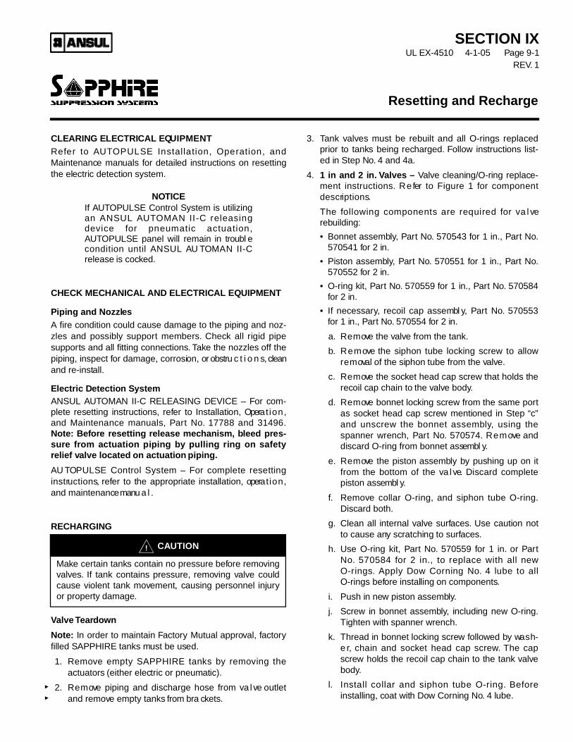
CLEARING ELECTRICAL EQU I P M E N TR e fer to AU TOPULSE Installation, Operation, andMaintenance manuals for detailed instructions on resettingthe electric detection system.
N OT I C EIf AU TOPULSE Control System is utilizingan ANSUL AU TOMAN II-C releasingd evice for pneumatic actuation,AU TOPULSE panel will remain in troubl econdition until ANSUL AU TOMAN II-Crelease is cocke d .
CHECK MECHANICAL AND ELECTRICAL EQU I P M E N T
Piping and NozzlesA fire condition could cause damage to the piping and noz-zles and possibly support members. C h e ck all rigid pipes u p p o rts and all fitting connections. Ta ke the nozzles off thepiping, inspect for damage, corrosion, or obstru c t i o n s, cleanand re-install.
Electric Detection SystemANSUL AU TOMAN II-C RELEASING DEVICE – For com-plete resetting instru c t i o n s, refer to Installation, Opera t i o n ,and Maintenance manu a l s, Pa rt No. 17788 and 31496.N o t e : B e fore resetting release mech a n i s m , bleed pres-sure from actuation piping by pulling ring on safe t yrelief valve located on actuation piping.
AU TOPULSE Control System – For complete resettingi n s t ru c t i o n s, refer to the appropriate installation, opera t i o n ,and maintenance manu a l .
RECHARGING
Valve Te a rd ow n
N o t e : In order to maintain Fa c t o ry Mutual approval, fa c t o ryfilled SAPPHIRE tanks must be used.
1 . R e m ove empty SAPPHIRE tanks by removing theactuators (either electric or pneumatic).
2 . R e m ove piping and discharge hose from va l ve outletand remove empty tanks from bra cke t s.
3 . Tank va l ves must be rebuilt and all O-rings replacedp rior to tanks being recharged. Fo l l ow instructions list-ed in Step No. 4 and 4a.
4 . 1 in and 2 in. Valves – Va l ve cleaning/O-ring replace-ment instru c t i o n s. R e fer to Figure 1 for componentd e s c ri p t i o n s.
The fo l l owing components are required for va l ver e bu i l d i n g :
• Bonnet assembl y, Pa rt No. 570543 for 1 in., Pa rt No.570541 for 2 in.
• Piston assembl y, Pa rt No. 570551 for 1 in., Pa rt No.570552 for 2 in.
• O - ring kit, Pa rt No. 570559 for 1 in., Pa rt No. 5 7 0 5 8 4for 2 in.
• If necessary, recoil cap assembl y, Pa rt No. 5 7 0 5 5 3for 1 in., Pa rt No. 570554 for 2 in.
a . R e m ove the va l ve from the tank.
b. R e m ove the siphon tube locking screw to allowr e m oval of the siphon tube from the va l ve.
c . R e m ove the socket head cap screw that holds therecoil cap chain to the va l ve body.
d . R e m ove bonnet locking screw from the same portas socket head cap screw mentioned in Step “ c ”and unscrew the bonnet assembl y, using thespanner wrench, Pa rt No. 5 7 0 5 7 4 . R e m ove anddiscard O-ring from bonnet assembl y.
e. R e m ove the piston assembly by pushing up on itfrom the bottom of the va l ve. Discard completepiston assembl y.
f. R e m ove collar O-ring, and siphon tube O-ri n g .Discard both.
g . Clean all internal va l ve surfa c e s. Use caution notto cause any scratching to surfa c e s.
h . Use O-ring kit, Pa rt No. 570559 for 1 in. or Pa rtN o. 570584 for 2 in., to replace with all newO-ri n g s. Apply Dow Corning No. 4 lube to allO-rings before installing on components.
i . Push in new piston assembl y.
j . S c r ew in bonnet assembl y, including new O-ri n g .Tighten with spanner wrench.
k . Thread in bonnet locking screw fo l l owed by wa s h-e r, chain and socket head cap screw. The caps c r ew holds the recoil cap chain to the tank va l veb o d y.
l . Install collar and siphon tube O-ri n g . B e fo r einstalling, coat with Dow Corning No. 4 lube.
Resetting and Recharge
S E C T I O N I XU L EX-4510 4-1-05 Page 9-1
R E V. 1
C AU T I O N!
M a ke certain tanks contain no pressure before remov i n gva l ve s. If tank contains pressure, removing va l ve couldcause violent tank movement, causing personnel injuryor property damage.
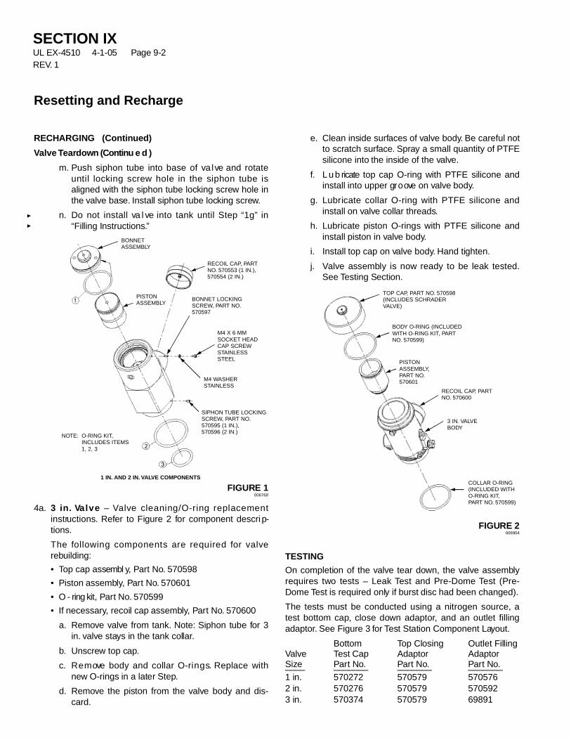
S E C T I O N I XU L EX-4510 4-1-05 Page 9-2R E V. 1
Resetting and Recharge
RECHARGING ( C o n t i nu e d )
Valve Te a rd own (Continu e d )
m . Push siphon tube into base of va l ve and rotateuntil locking screw hole in the siphon tube isaligned with the siphon tube locking screw hole inthe va l ve base. Install siphon tube locking screw.
n . Do not install va l ve into tank until Step “ 1 g ” i n“Filling Instru c t i o n s.”
FIGURE 1006768
4 a . 3 in. Va l v e – Va l ve cleaning/O-ring replacementi n s t ru c t i o n s. R e fer to Figure 2 for component descri p-t i o n s.
The fo l l owing components are required for va l ver e bu i l d i n g :
• Top cap assembl y, Pa rt No. 5 7 0 5 9 8
• Piston assembl y, Pa rt No. 5 7 0 6 0 1
• O - ring kit, Pa rt No. 5 7 0 5 9 9
• If necessary, recoil cap assembl y, Pa rt No. 5 7 0 6 0 0
a . R e m ove va l ve from tank. N o t e : Siphon tube for 3i n . va l ve stays in the tank collar.
b. U n s c r ew top cap.
c . R e m ove body and collar O-ri n g s. Replace withn ew O-rings in a later Step.
d . R e m ove the piston from the va l ve body and dis-c a r d .
e. Clean inside surfaces of va l ve body. Be careful notto scratch surfa c e. S p ray a small quantity of PTFEsilicone into the inside of the va l ve.
f. L u b ricate top cap O-ring with PTFE silicone andinstall into upper gr o ove on va l ve body.
g . L u b ricate collar O-ring with PTFE silicone andinstall on va l ve collar threads.
h . L u b ricate piston O-rings with PTFE silicone andinstall piston in va l ve body.
i . Install top cap on va l ve body. Hand tighten.
j . Va l ve assembly is now ready to be leak tested.See Testing Section.
FIGURE 2006904
T E S T I N G
On completion of the va l ve tear down, the va l ve assembl yrequires two tests – Leak Test and Pre-Dome Test (Pre-Dome Test is required only if burst disc had been changed).
The tests must be conducted using a nitrogen source, atest bottom cap, close down adaptor, and an outlet fillinga d a p t o r. See Figure 3 for Test Station Component Layo u t .
B o t t o m Top Closing Outlet FillingVa l ve Test Cap A d a p t o r A d a p t o rS i ze Pa rt No. Pa rt No. Pa rt No._ _ _ _ _ _ _ _ _ _ _ _ _ _ _ _ _ _ _ _ _ _ _ _ _1 in. 5 7 0 2 7 2 5 7 0 5 7 9 5 7 0 5 7 62 in. 5 7 0 2 7 6 5 7 0 5 7 9 5 7 0 5 9 23 in. 5 7 0 3 7 4 5 7 0 5 7 9 6 9 8 9 1
TOP CAP, PART NO. 570598(INCLUDES SCHRADERVALVE)
BODY O-RING (INCLUDEDWITH O-RING KIT, PARTNO. 570599)
RECOIL CAP, PARTNO. 570600
3 IN. VALVEBODY
COLLAR O-RING(INCLUDED WITHO-RING KIT,PART NO. 570599)
PISTONASSEMBLY,PART NO.570601
BONNETASSEMBLY
RECOIL CAP, PARTNO. 570553 (1 IN.),570554 (2 IN.)
BONNET LOCKINGSCREW, PART NO.570597
M4 X 6 MMSOCKET HEADCAP SCREWSTAINLESSSTEEL
SIPHON TUBE LOCKINGSCREW, PART NO.570595 (1 IN.),570596 (2 IN.)
1 IN. AND 2 IN. VALVE COMPONENTS
M4 WASHERSTAINLESS
NOTE: O-RING KIT,INCLUDES ITEMS1, 2, 3
PISTONASSEMBLY
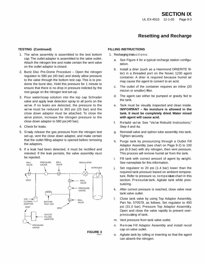
S E C T I O N I XU L EX-4510 12-1-03 Page 9-3
Resetting and Recharge
T E S T I N G ( C o n t i nu e d )
1 . The va l ve assembly is assembled to the test bottomc a p. The outlet adaptor is assembled to the va l ve outlet.Attach the nitrogen line and make certain the vent va l veon the outlet adaptor is closed.
2 . Burst Disc Pre-Dome Procedure – Open the nitrogenregulator to 580 psi (40 bar) and slowly allow pressureto the va l ve through the bottom test cap. This is to pre-dome the burst disc. Hold this pressure for 1 minute toensure that there is no drop in pressure indicted by therest gauge on the nitrogen test set-up.
3 . Pour water/soap solution into the top cap Schra d e rva l ve and apply leak detection spray to all ports on theva l ve. If no leaks are detected, the pressure to theva l ve must be reduced to 363 psi (25 bar) and theclose down adaptor must be attached. To close theva l ve piston, increase the nitrogen pressure to theclose down adaptor to 580 psi (40 bar).
4 . C h e ck for leaks.
5 . S l owly release the gas pressure from the nitrogen tests e t - u p, vent the close down adaptor, and make cert a i nthat the outlet filling adaptor is opened before remov i n gthe adaptors.
6 . If a leak had been detected, it must be rectified andr e t e s t e d . If the leak persists, the va l ve assembly mu s tbe rejected.
FIGURE 3004977
FILLING INSTRU C T I O N S
1 . Recharging Instru c t i o n s :
a . See Figure 4 for a typical recharge station configu-ra t i o n .
b. Install a drier (such as a Hammond DRIERITE fil-ter) in a threaded port on the Novec 1230 agentc o n t a i n e r. A drier is required because humid airm ay cause the agent to conve rt to an acid.
c . The outlet of the container requires an inline (20micron or smaller) filter.
d . The agent can either be pumped or gravity fed tothe tank.
e. Tank must be visually inspected and clean inside.I M P O RTANT – No moisture is allowed in thet a n k . It must be completely dried. Water mixe dwith agent will cause acid.
f. R e build va l ve. See “ Va l ve Rebuild Instru c t i o n s,”Step 4 and 4a.
g . Reinstall va l ve and siphon tube assembly into tank.Tighten securely.
h . Purge tank by pressurizing through a Outlet FillAdaptor Assembly (see chart on Page 9-2) to 100psi (6.9 bar) with dry nitrogen, then vent pressure.This process will remove humid air from the tank.
i . Fill tank with correct amount of agent by we i g h t .See nameplate for this info rm a t i o n .
j . Set regulator to 20 psi (1.4 bar) lower than therequired tank pressure based on ambient tempera-t u r e. R e fer to pressure vs. t e m p e rature chart in thiss e c t i o n . P r e s s u ri ze tank. Agitate tank while pres-s u ri z i n g .
k . After correct pressure is reached, close va l ve neartank va l ve outlet.
l . Close tank va l ve by using Top Adaptor Assembl y,Pa rt No. 570579, as fo l l ow s. Set regulator to 450psi (31.0 bar). Pressure Top Adaptor Assembl y.Open and close the va l ve rapidly to prevent ove r -p r e s s u rizing of tank.
m . Vent pressure from tank va l ve outlet.
n . R e m ove Fill Adaptor Assembly and install recoilcap on va l ve outlet.
o. Agitate tank by rolling or inve rting so that the agentcan absorb the nitrogen.
PRESSUREGAUGE
PRESSUREGAUGE
PRESSUREGAUGE
BOTTOMTEST CAP
NITROGEN
OUTLETFILLINGADAPTOR
VENT
VENT
VENT
BALLVALVE
REGULATORBALLVALVE
BALLVALVE
TOPCLOSINGADAPTOR
BALLVALVE
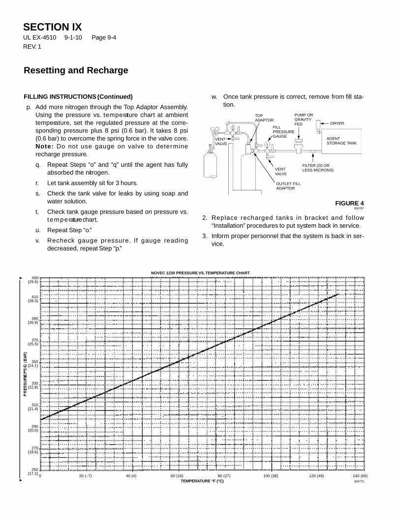
S E C T I O N I XU L EX-4510 9-1-10 Page 9-4
R E V. 1
Resetting and Recharge
FILLING INSTRUCTIONS ( C o n t i nu e d )
p. Add more nitrogen through the Top Adaptor Assembl y.Using the pressure vs. t e m p e rature chart at ambientt e m p e ra t u r e, set the regulated pressure at the corre-sponding pressure plus 8 psi (0.6 bar). It takes 8 psi( 0 . 6 bar) to overcome the spring force in the va l ve core.N o t e : Do not use gauge on va l ve to determ i n erecharge pressure.
q . Repeat Steps “ o ” and “ q ” until the agent has fullyabsorbed the nitrogen.
r. Let tank assembly sit for 3 hours.
s. C h e ck the tank va l ve for leaks by using soap andwater solution.
t . C h e ck tank gauge pressure based on pressure vs.t e m p e rature chart .
u . Repeat Step “ o.”
v. R e c h e ck gauge pressure. If gauge readingdecreased, repeat Step “ p.”
w. Once tank pressure is correct, remove from fill sta-t i o n .
FIGURE 4006767
2 . Replace recharged tanks in bra cket and fo l l ow“ I n s t a l l a t i o n ” procedures to put system back in serv i c e.
3 . I n fo rm proper personnel that the system is back in ser-v i c e.
NOVEC 1230 PRESSURE VS. TEMPERATURE CHART430
(29.6)
410(28.3)
390(26.9)
370(25.5)
350(24.1)
330(22.8)
310(21.4)
290(20.0)
270(18.6)
250(17.2)
0 20 (–7) 40 (4) 60 (16) 80 (27) 100 (38) 120 (49) 140 (60)TEMPERATURE °F (°C) 006770
AGENTSTORAGE TANK
FILTER (20 ORLESS MICRONS)
FILLPRESSUREGAUGE
VENTVALVE
VENTVALVE
PUMP ORGRAVITYFED DRYER
OUTLET FILLADAPTOR
TOPADAPTOR
SECTION XUL EX-4510 9-1-10 Page 10-1
REV. 2
Electronic data processing involves storage, recall and useof information via electronic equipment. Electronic data pro-cessing equipment is found in almost every industry today.The equipment is very sensitive and operates within minutetolerances. Additionally, many computer installations aredesigned with a subfloor area containing data and powercable bundles.
Because of the high dollar valve of the equipment, the datamanaged by that equipment and the productivity providedby electronic data processing, rapid detection and efficientfire protection are imperative. Time lost to cleanup and ven-tilation of a computer room means lost time throughout thecompany, so these areas require a clean, no residue gasagent that disperses easily.
The computer room and subfloor space can be protectedwith an SAPPHIRE suppression system, even when thecomputer room is normally occupied.
Fires can occur within the computer electrical insulation andin the cable bundles in the subfloor. Paper debris that hasbeen allowed to accumulate in the subfloor is also a sourceof fuel.
Computer room/subfloor protection can be accomplished byinstallation of a total flood SAPPHIRE system. Thesystem is designed in accordance with the ANSUL design,installation manual and NFPA Standard 2001, “Standard forClean Agent Fire Extinguishing Systems.” It is importantthat an effective agent concentration not only be achieved,but shall be maintained for a sufficient period of time toallow effective emergency action by trained personnel.”
The SAPPHIRE system consists of a tank(s), a pipingarrangement and discharge nozzles located in the comput-er room, storage room, and subfloor space.
Occasionally, drainage is installed in the subfloor area.Provisions must be made for making the drain piping aclosed system unless water is present to assist in assuringthe necessary concentration.
When the computer room is normally occupied, personnelsafety is of first concern. Alarms or warning devices mustbe located in the room to provide sufficient annunciation ofagent discharge. The rooms and subfloor must be tight toprevent loss of agent.
All air handling equipment must be shut down anddampered prior to system discharge.
Smoke detectors, operated by an electronic control panel,are usually employed with a SAPPHIRE system to providedetection and thus suppression of a fire before it has achance to do serious damage.
The authority having jurisdiction may have additionalrequirements.
HAZARD
• A computer room having dimensions of 46 ft x 20 ft x 10 ft(14.0 m x 6.1 m x 3.1 m)
• A storage room having dimensions of 12 ft x 12 ft x 10 ft(3.7 m x 3.7 m x 3.1 m)
• A subfloor having dimensions of 46 ft x 20 ft x 1 ft (14.0 mx 6.1 m x 0.3 m)
• No unclosable openings.
• Ventilation to be shut down at system actuation.
Example – Computer Room,Storage Room, and Subfloor
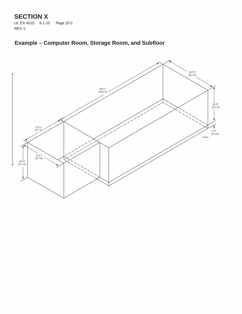
SECTION XUL EX-4510 9-1-10 Page 10-2
REV. 1
Example – Computer Room, Storage Room, and Subfloor
10 FT.(3.1 m)
10 FT.(3.1 m)
12 FT.(3.7 m)
46 FT.(14.0 m)
1 FT.(0.3 m)
12 FT.(3.7 m)
006891
20 FT.(6.1 m)
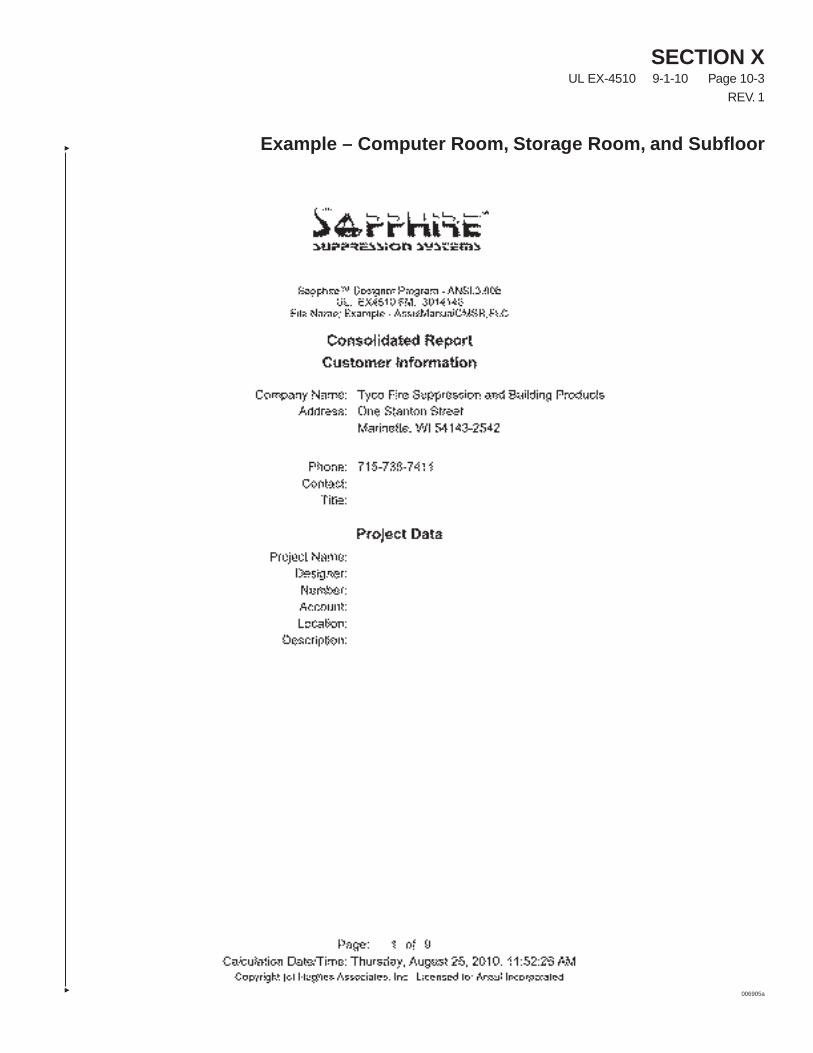
SECTION XUL EX-4510 9-1-10 Page 10-3
REV. 1
Example – Computer Room, Storage Room, and Subfloor
006905a
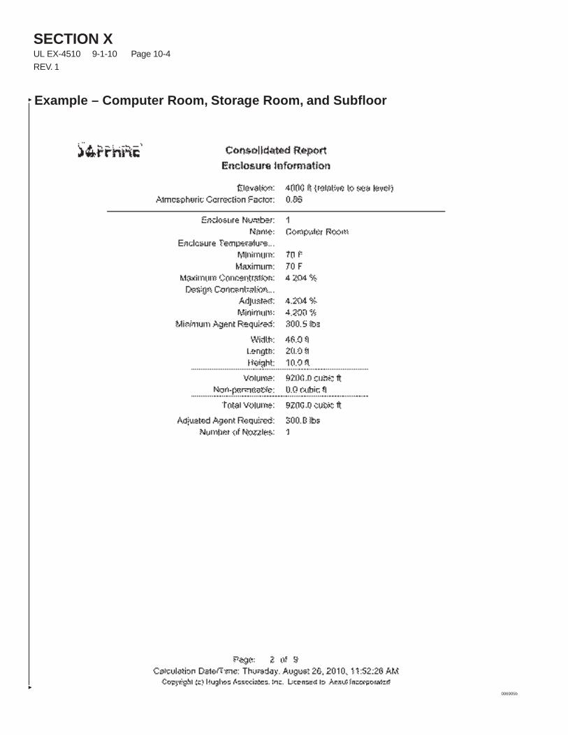
SECTION XUL EX-4510 9-1-10 Page 10-4
REV. 1
Example – Computer Room, Storage Room, and Subfloor
006905b
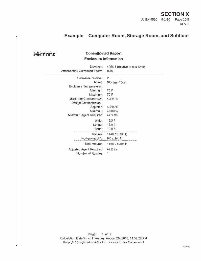
SECTION XUL EX-4510 9-1-10 Page 10-5
REV. 1
Example – Computer Room, Storage Room, and Subfloor
006905c
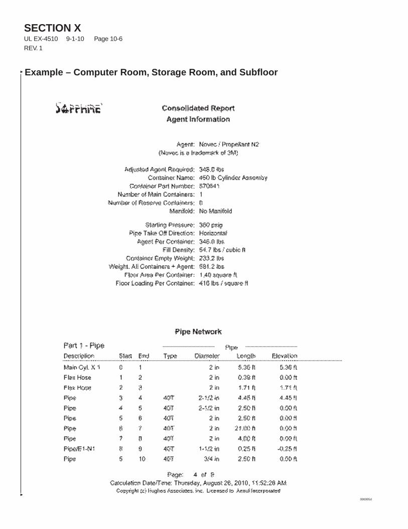
SECTION XUL EX-4510 9-1-10 Page 10-6
REV. 1
Example – Computer Room, Storage Room, and Subfloor
006905d
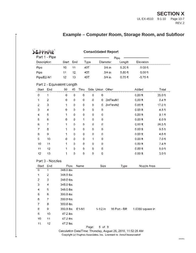
SECTION XUL EX-4510 9-1-10 Page 10-7
REV. 2
Example – Computer Room, Storage Room, and Subfloor
006905e
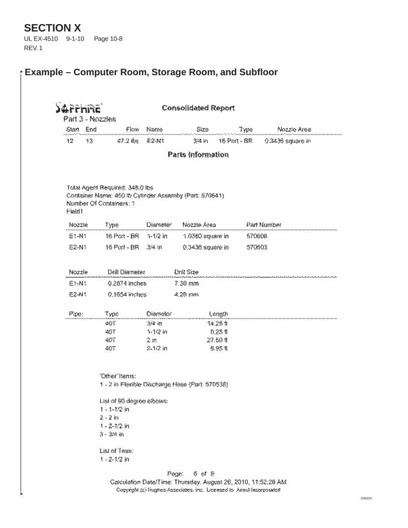
SECTION XUL EX-4510 9-1-10 Page 10-8
REV. 1
Example – Computer Room, Storage Room, and Subfloor
006905f
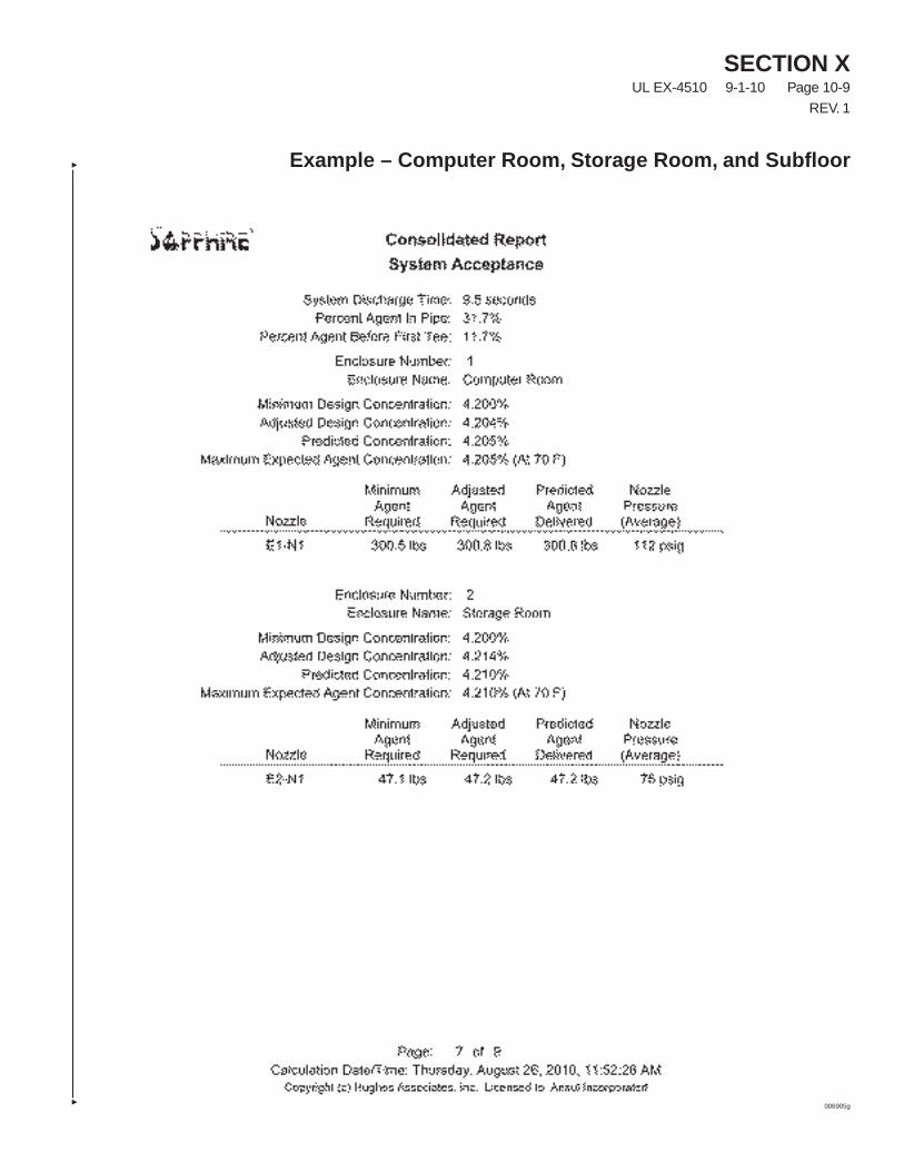
SECTION XUL EX-4510 9-1-10 Page 10-9
REV. 1
Example – Computer Room, Storage Room, and Subfloor
006905g
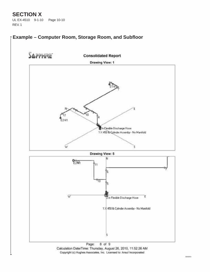
SECTION XUL EX-4510 9-1-10 Page 10-10
REV. 1
Example – Computer Room, Storage Room, and Subfloor
006905h
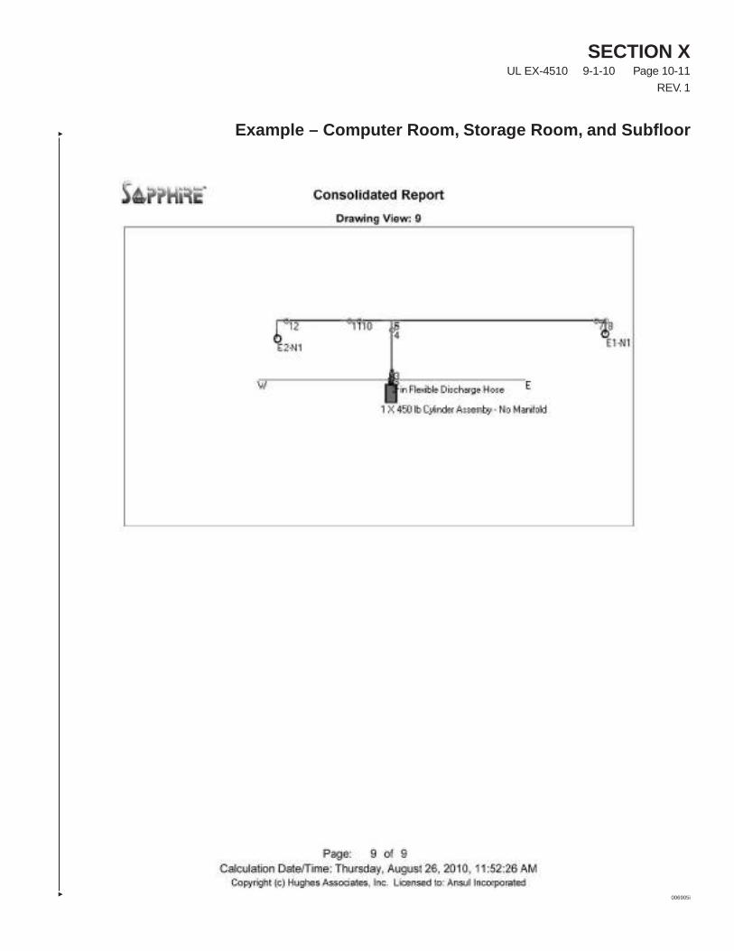
SECTION XUL EX-4510 9-1-10 Page 10-11
REV. 1
Example – Computer Room, Storage Room, and Subfloor
006905i
SECTION XUL EX-4510 9-1-10 Page 10-12
REV. 1
Example – Computer Room, Storage Room, and Subfloor
006906a
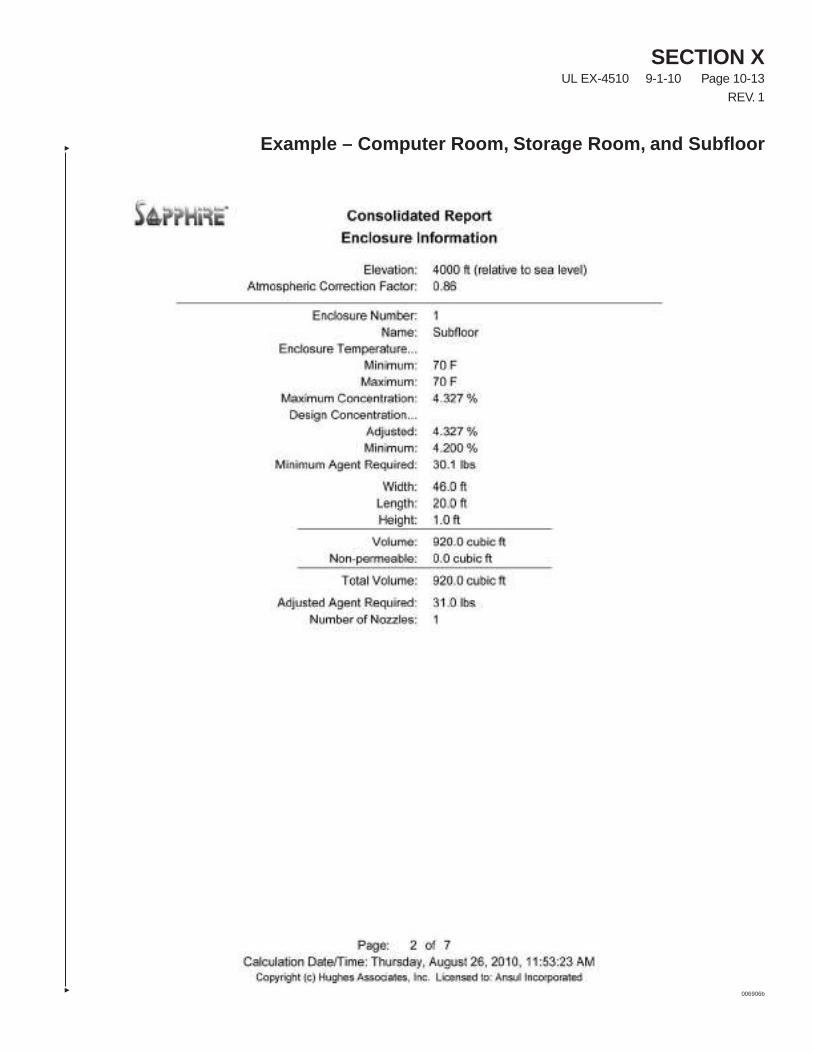
SECTION XUL EX-4510 9-1-10 Page 10-13
REV. 1
Example – Computer Room, Storage Room, and Subfloor
006906b
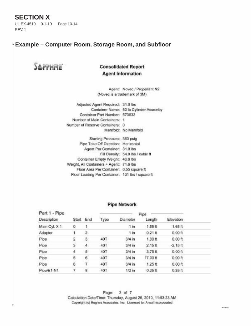
SECTION XUL EX-4510 9-1-10 Page 10-14
REV. 1
Example – Computer Room, Storage Room, and Subfloor
006906c
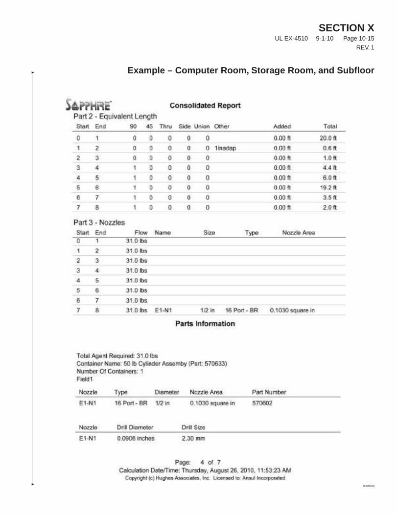
SECTION XUL EX-4510 9-1-10 Page 10-15
REV. 1
Example – Computer Room, Storage Room, and Subfloor
006906d
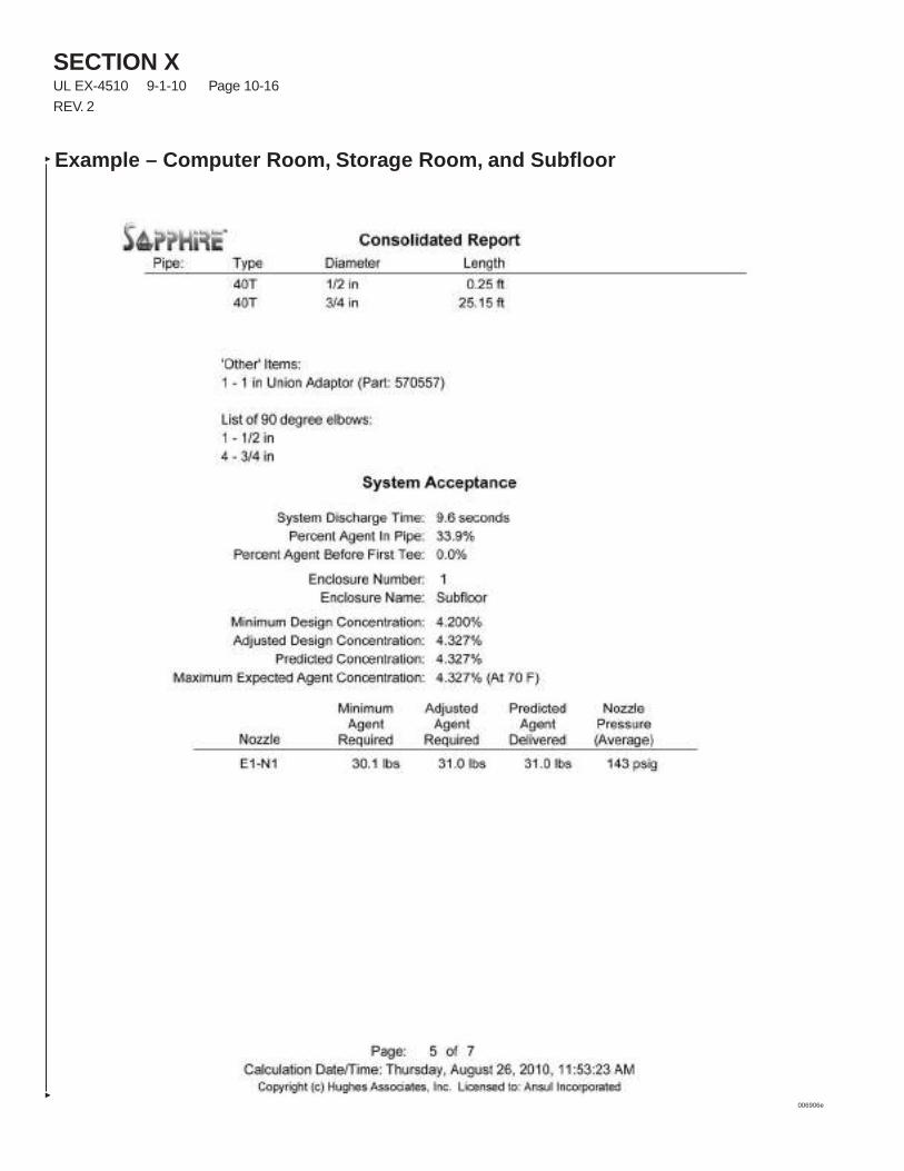
SECTION XUL EX-4510 9-1-10 Page 10-16
REV. 2
Example – Computer Room, Storage Room, and Subfloor
006906e
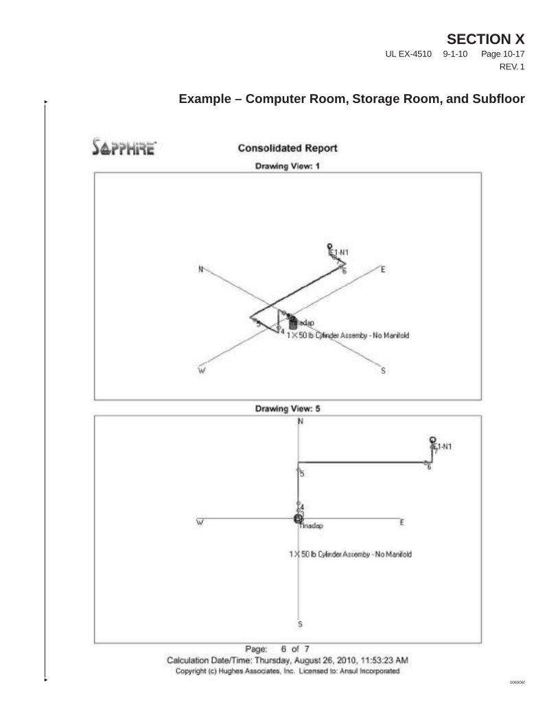
SECTION XUL EX-4510 9-1-10 Page 10-17
REV. 1
Example – Computer Room, Storage Room, and Subfloor
006906f
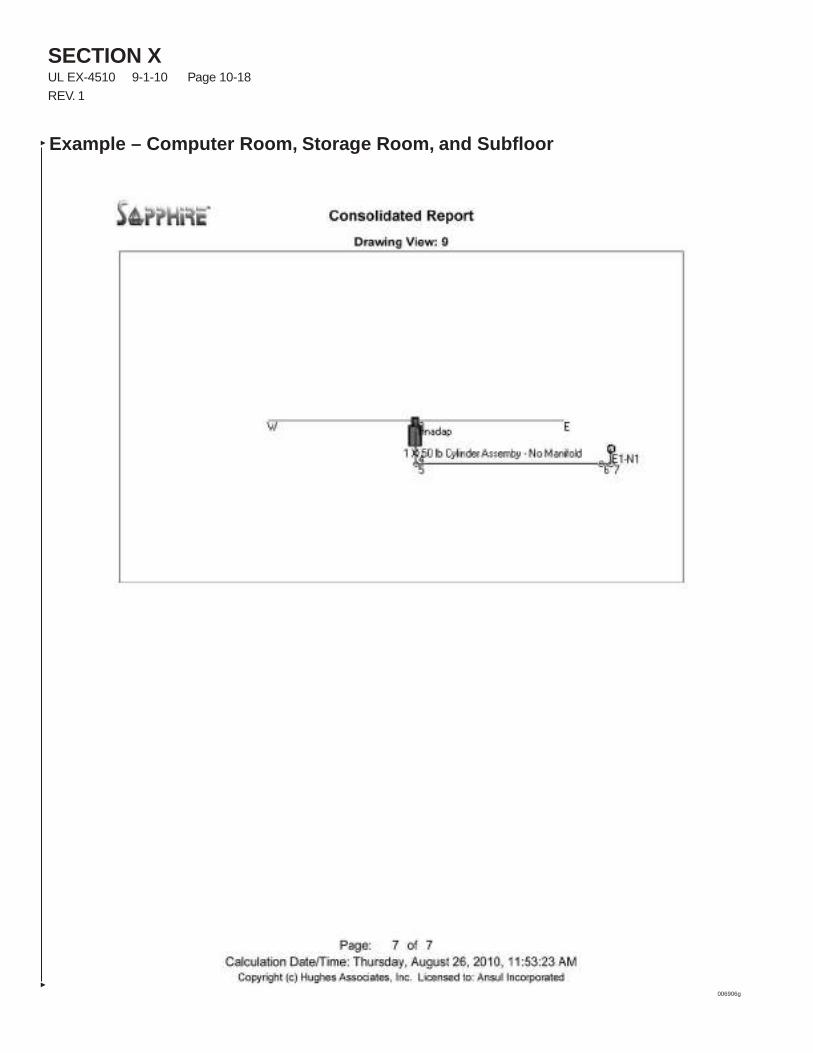
SECTION XUL EX-4510 9-1-10 Page 10-18
REV. 1
Example – Computer Room, Storage Room, and Subfloor
006906g