annual reviews in control - edisciplinas.usp.br · engine management system (ems) usually consists...
TRANSCRIPT

Annual Reviews in Control 41 (2016) 94–118
Contents lists available at ScienceDirect
Annual Reviews in Control
journal homepage: www.elsevier.com/locate/arcontrol
Review
A review on control system architecture of a SI engine management
system
B. Ashok
∗, S. Denis Ashok, C. Ramesh Kumar
School of Mechanical Engineering (SMEC), VIT University, Vellore 632014, India
a r t i c l e i n f o
Article history:
Received 28 May 2015
Revised 28 January 2016
Accepted 15 February 2016
Available online 5 May 2016
Keywords:
Engine management system (EMS)
SI engine control algorithm
Sub-control module
Control system architecture
Torque
a b s t r a c t
Engine management systems (EMS) has become an essential component of a spark ignition (SI) engine in
order to achieve high performance; low fuel consumption and low exhaust emissions. An engine manage-
ment system (EMS) is a mixed-signal embedded system interacting with the engine through number of
sensors and actuators. In addition, it includes an engine control algorithm in the control unit. The control
strategies in EMS are intended for air-to-fuel ratio control, ignition control, electronic throttle control,
idle speed control, etc. Hence, the control system architecture of an EMS consists of many sub-control
modules in its structural design to provide an effective output from the engine. Superior output from
the engine is attained by the effective design and implementation of the control system in EMS. The de-
sign of an engine control system is a very challenging task because of the complexity of the functions
involved. This paper consolidates an overview of the vital developments within the SI engine control sys-
tem strategies and reviews about some of the basic control modules in the engine management system.
© 2016 International Federation of Automatic Control. Published by Elsevier Ltd. All rights reserved.
t
t
o
o
s
s
s
g
T
m
n
s
e
E
1
3
t
c
p
(
&
e
1. Introduction
Enhancements in fuel economy and emission reductions are
two active areas of engine research. Advanced engine control tech-
niques are engaged because of the strict emission regulations and
demand for higher fuel economy. It is of great importance to de-
sign the power train components in order to improve the fuel ef-
ficiency and reduce emissions while fulfilling drivability and ride
comfort issues. Control has always been a part of engine design
and it is one of the most complex problems in the application
( Stobart, Challen, & Bowyer, 2001 ). Automobile engines effectively
encompass the spirit of mechatronic systems with their abundant
application of electronics, sensors, actuators and microprocessor
based control systems to provide improved performance, fuel econ-
omy and emission levels. The classical approach of engine-control
tasks is accomplished by means of a mechanical approach, but now
it is being replaced by electronic control systems. In such systems,
engine performance such as power, torque, fuel-consumption and
emission level, is significantly affected by the control strategies
followed in the engine management system (EMS) ( Lee, Park, &
Sunwoo, 2004 ). The modern spark ignition engines are generally
equipped with an EMS whose task is to provide the desired output
from the engine and it plays an important role in the driver’s con-
∗ Corresponding author. Tel.: + 91 9865467729.
E-mail address: [email protected] , [email protected] (B. Ashok).
&
L
p
s
http://dx.doi.org/10.1016/j.arcontrol.2016.04.005
1367-5788/© 2016 International Federation of Automatic Control. Published by Elsevier Lt
rol of the vehicle. It controls the operations such as ignition, air-
o-fuel ratio, idle speed and complex variable valve timing, etc., in
rder to reduce the emissions and improve the average fuel econ-
my ( George & Michael, 2014 ). Compared with ordinary embedded
ystems, it requires more stringent demands on reliability, resource
haring and cost efficiency ( Guojun, Wenqing, & Youtong, 2010 ).
Engine management system (EMS) usually consists of various
ensors to monitor the real-time operating conditions of the en-
ine and actuators to control injector, spark plug, throttle, etc.
he control signal sent to different actuators is accomplished by
eans of the EMS control system, which is comprised of a large
umber of control modules (control loops) in its architecture. The
chematic representation of the control system architecture of SI
ngine is shown in Fig. 1 . Some of the basic modules within the
MS which are coordinated with the torque control module are,
) air–fuel ratio (AFR) control; 2) electronic throttle control (ETC);
) idle speed control; 4) ignition timing control; 5) knock con-
rol; 6) diagnostics control, etc. Besides these modules, cam shaft
ontrol, turbocharger, EGR, after treatment controls, etc. are also a
art of the control modules in an actual production vehicle EMS
Andreas & Torsten, 2001; Guenther & Gerhardt, 20 0 0; Guzzella
Onder, 2010; Hammel, Jessen, Andreas, & Harald, 2003; Hillion
t al., 2008; Hong et al., 2013; Isermann, 2014 ; Jurgen, Honninger,
Bischof, 1998; Le Solliec, Berr, Colin, Corde, & Chamaillard, 2007;
e Solliec et al., 2007; Ribbens, 1998 ). All these modules are run in
arallel to the torque control structure in order to produce the de-
ired engine output as demanded by the driver. Other modules are
d. All rights reserved.

B. Ashok et al. / Annual Reviews in Control 41 (2016) 94–118 95
c
t
t
l
r
d
r
g
e
g
m
t
t
t
i
(
G
(
t
i
t
m
g
m
i
t
c
b
s
e
m
i
t
e
H
M
s
e
t
T
l
t
t
p
b
w
t
v
c
s
t
(
m
I
p
r
m
b
t
G
S
e
t
2
B
2
M
&
f
H
&
W
R
2
e
T
S
1
K
S
m
2
t
d
C
L
2
1
E
C
&
e
T
E
2
2
Y
&
s
2
2
2
J
t
2
r
Y
i
B
&
2
2
e
&
1
(
p
a
i
t
a
w
p
e
s
(
r
i
t
oordinated with the torque control module in order to accomplish
he engine output for the torque demand. The coordinated overall
orque reference value is realized by the manipulation of variables
ike throttle position, ignition timing, injection timing, etc. by the
espective actuators. Hence, the torque control module is the fun-
amental part of the entire engine control system architecture.
The control functions are managed by software control algo-
ithms in the EMS. The design and implementation of control al-
orithms is a crucial element in the development of automotive
ngine-control systems because of different operating modes of en-
ines such as: the start-up mode, idling mode, normal operation
ode, high power output mode, etc. Once the engine is started,
he EMS must make a judgment about the engine operating condi-
ions according to the data collected by different sensors. Through
his process the EMS calculates and adjusts the injection time,
gnition advance, throttle angle, etc. by the respective actuators
Isermann & Michael, 2001; Kiencke & Nielsen, 2005; Wang, Yu,
omm, Page, & Douglas, 2006 ). The engine management system
EMS) coordinates with other vehicle control systems (cruise con-
rol, ABS, ESP, etc.) for enhanced vehicle performance and handling.
The application layer of the software architecture in the EMS
s the separation of the engine functions from the vehicle func-
ions. The vehicle functions include all the concerns of powertrain
anagement within the vehicle, that are not specific to the en-
ine combustion like electrical supply system, thermal manage-
ent system, vehicle speed governor, etc. Started as a standalone
njection control system in SI engines, the modern EMS includes
he other control algorithm such as torque coordination, ignition
ontrol, throttle control, knock control, diagnostic controls, tur-
ocharger control, etc. All of these algorithms are in the application
oftware architecture of an EMS ( Hammel et al., 2003 ). Currently,
ngine control algorithms are mostly accomplished by a mathe-
atical model-based design and non-linear feedforward control is
mplemented using engine maps, i.e., matrix-based lookup tables
hat have been derived through extensive engine test bench op-
rations during calibration ( Gonzalez, Florez, & Arab, 2008; Huan,
uang, Dai, & Hu, 2014; Krishnaswami, Luh, & Rizzoni, 1995;
arkus, Johansson, & McKelvey, 2014 ). An engine management
ystem has hundreds of functions with thousands of parameters;
ach of these functions needs to be properly calibrated and tested
ogether with the other electronic control unit (ECU) software.
hese calibration processes are usually complicated and include a
ot of test contents. The main contents are steady state calibration
ests, transient operation, idle operation, covering a lot of parame-
ers including fuel parameters like fuel injection timing, ignition
arameters like ignition advance, etc. in the form of lookup ta-
les. All of such lookup tables are part of the control algorithms
hich are stored in the memory of the controller. Also, the con-
rol system should be robust with respect to process parameter
ariations caused by production deviations, variations of external
onditions (e.g. temperature), and aging. And finally, the control
trategy should have a simple structure, convenient for implemen-
ation on a typical low-cost automotive microcontroller system
Eriksson & Nielsen, 2014; Lumpp, Tanimou, Bouillon, & Muenzen-
ay, 2014; Tomohiko & Hayakawa, 2011; Wong, Tam, & Ke, 2012 ).
n recent years, many control theories have been successfully ap-
lied to engine control systems. For example, PID control, recur-
ent neural network, trainable fuzzy control, adaptive control, opti-
al control, H ∞
control, hybrid control and nonlinear control have
een used to control the different control modules such as engine
orque control ( Gafvert, Arzen, Bernhardsson, & Pedersen, 20 0 0,
afvert, Arzen, Pedersen, & Bernhardsson, 2004; Heintz, Mews,
tier, Beaumont, & Noble, 2001 ; Jurgen et al., 1998; Le Solliec, Berr
t al., 2007, Le Solliec et al., 2007; Petrovich, 2000 ), air–fuel ra-
io ( Al-Himyari, Yasin, & Gitano, 2014; Alain, Vigild, & Hendricks,
0 0 0; Alexander & Kolmanovsky, 20 02; Anurak & Sooraksa, 2012;
ehrouz et al., 2012; Bin, Shen, Kako, & Ouyang, 2008; Dickinson,
0 09; Feng et al., 20 06; Ferdinando & Lavorgna, 2006; Franceschi,
uske, Peyton Jones, & Makki, 2007; Franchek Matthew, Mohrfeld,
Osburn, 2006; Grizzle, Cook, & Milam, 1994 ; Guo, Baiyu, Yun-
en, & Hong, 2013; Haiping & Qian, 2010; Hajime et al., 2002 ;
olzmann, Halfmann, & Isermann, 1997; Ivan, Marotta, Pianese,
Sorrentino, 2006; Kahveci Nazli & Jankovic, 2010; Kwiatkowski,
erner, Blath, Ali, & Schultalbers, 2009; Mayr Christian, Euler-
olle, Kozek, Hametner, & Jakubek, 2014; Nicolo, Corti, & Moro,
010; Per, Olsen, Poulsen, Vigild, & Hendricks, 1998; Rajagopalan
t al., 2014; Roberto, Villante, & Sughayyer, 2005; Rui, Li, Dong, &
ang, 2009; Sardarmehni, Keighobadi, Menhaj, & Rahmani, 2013;
huntaro, Kato, Kako, & Ohata, 2009; Sei-Bum, Won, & Hedrick,
994; Seungbum, Yoon, & Sunwoo, 2003; Stroh David, Franchek, &
erns, 2001; Tseng & Cheng, 1999; Winge, Andersen, Hendricks, &
truwe, 1999; Yildiray, 2009; Yildiray, Annaswamy, Yanakiev, & Kol-
anovsky, 2010; Yildiray, Annaswamy, Yanakiev, & Kolmanovsky,
0 08; Zhai & Yu, 20 09; Zhai, Yu, Tafreshi, & Al-Hamidi, 2011 ),
hrottle control ( Al-samarraie & Abbas, 2012; Alt et al., 2010; An-
reas & Eriksson, 2009; Aono & Kowatari, 2006; Chen & Ran, 2009;
hen, Lin, & Wei, 2012; Chen, Tsai, & Lin, 2010; Chen, Tsai, &
in, 2010; Chris & Watson, 2003 ; Danijel, Deur, Jansz, & Peric,
006; Deur, Pavkovi, Peri, Jansz, & Hrovat, 2004; Devor & Sun,
997; Di Bernardo, Montanaro, Santini, di Gaeta, & Giglio, 2009;
iji, Ishiguro, Yasui, & Akazaki, 2003; Feru et al., 2012; Giulio,
orno, & Savaresi, 2013; Grepl & Lee, 2010; Griffiths, 2002; Jae
Byun, 1999; Lars & Nielsen, 20 0 0; Mercorelli, 2009; Montanaro
t al., 2014; Nakano et al., 2006; Shugang, Smith, & Kitchen, 2009;
akeru, Asada, Tsuyuguchi, Yamazaki, & Hotta, 2009; Thomasson &
riksson, 2011; Thornhill & Sindano, 20 0 0; Toshihiro & Kowatari,
001; Umit, Hong, & Pan, 2001; Wang et al., 2010; Wang & Huang,
013; Yang, 2004; Yurkovich & Li, 2005; Xiaofang & Wang, 2009;
ildiz, Annaswamy, Yanakiev, & Kolmanovsky, 2007; Yuan, Wang,
Wu, 2008; Zeng & Wan, 2011; Zhang, Yang, & Zhu, 2014 ), idle
peed ( Chamaillard et al., 2004; Danijel, Deur, & Kolmanovsky,
009; di Gaeta, Montanaro, & Giglio, 2010; Feng-Chi, Chen, & Wu,
007; Howell & Best, 2000; Jacek, 2010; Jingshun & Kurihara,
003; Jiangyan, Shen, & Marino, 2010; Josko, Ivanovi, Pavkovi, &
ansz, 2004; Kong, Yuhua, Xiaoguang, & Xigeng, 2006; Luigi, San-
ini, & Serra, 1999; Manivannan, 2011; Nicolo et al., 2003; Scillieri,
002; Singh, Vig, & Sharma, 2002; Stefan & Eriksson, 2006; Sub-
amaniam, Dessert, Sharma, & Yasin, 2002; Yildiray, Annaswamy,
anakiev, & Kolmanovsky, 2011 Yildiz et al., 2007 ), ignition tim-
ng ( Arno, Layher, & Däschner, 2012; Baitao, Wang, & Prucka, 2013;
hot & Quayle, 1982; Czarnigowski, Wendeker, Jakli ́nski, Boulet,
Breaban, 2007; Desheng, Yunfeng, & Hong, 2014; Enrico et al.,
014; Eriksson & Nielsen, 1997; Go-Long, Wu, Chen, & Chuang,
004; Herbert & Ploeger, 2007; Huang & Chen, 2006; Masatake
t al., 2001; Raducanu, Arotaritei, & Dimitriu, 2001; Saravana Prabu
Naiju, 2009; Yankun & Liu, 2010; Zhengmao, 2001; Zhang et al.,
999; Zhihu & Run, 2008 ), etc. in the engine management system
EMS). As there are different types control approaches and com-
lexity are involved in the engine control system, this review paper
ims to summarize the some of the basic engine control modules,
n a collective approach.
Existing research activities were focused on describing the par-
icular control module and its development rather than a holistic
pproach of engine control system development. This review paper
ill serve as a fundamental guide for future studies to improve the
erformance aspects of the EMS control system architecture of a SI
ngine. In this paper, an attempt is made to review some of the ba-
ic and essential control modules in an engine management system
EMS) of an SI engine. This review paper will not enforce any new
esults, rather than it will gives a combined approach of the var-
ous research activities on the engine control system and discuss
he future prospects of SI engine controls. The paper is organized

96 B. Ashok et al. / Annual Reviews in Control 41 (2016) 94–118
Fig. 1. Schematic representation of the EMS control system in a SI engine.
a
s
t
c
t
a
t
t
t
d
T
F
a
d
t
f
t
p
(
s
m
w
t
s
e
c
e
t
d
e
g
s
t
c
l
c
a
c
2
in multiple sections, Section 2 deals with the torque based engine
module, followed by Section 3 which deals with the air fuel ratio
control module, Section 4 with electronic throttle control, Section
5 discuss idle speed control, and Section 6 with ignition control
module. Where Section 7 deals with knock detection and control
module and Section 8 describes the diagnostic system in the EMS.
2. Torque based engine control module
Due to the increasing complexity of engine control systems
and the integration of vehicle control systems, torque-based en-
gine control strategies come into usage ( Chamaillard et al., 2004;
Ml, Minghui, & Anthony, 2008 ). The torque-based system can easily
interact with external torque interfaces (transmission, traction con-
trol, etc.). The torque based EMS control module converts the var-
ious inputs into the engine torque variable, which is used as the
major interface between the engine control unit and other func-
tionalities inside the vehicle control system. The coordination be-
tween engine control, transmission control and brake control, etc.
is also accomplished through this torque variable. Hence, based on
the physical value of torque, all demands can be coordinated be-
fore the optimal conversion to the respective engine control val-
ues takes place. As the torque demands are originating from the
driver and also form the engine management functions (i.e. en-
gine start, idle speed control, catalyst heating), external subsystems
like the transmission control unit, the cruise control system, trac-
tion control system, etc. ( Guenther & Gerhardt, 20 0 0; Heintz et al.,
2001 ). Engine torque control provides coordination of engine ac-
tuators (throttle position, spark advance, cam phase positions and
others) to achieve torque requested by driver or a vehicle subsys-
tem. Some of the research works carried on the torque based con-
trol module are listed in Table 1 . The torque- based engine control
system was initially presented by Bosch and applied in Bosch ME7
version engine management system (EMS). Nowadays this kind of
coordinated powertrain control system has become a standard in
the automotive industry. All powertrain control suppliers develop
solutions to provide coordinated powertrain torque control.
From the research work listed above it is evident that, initially a
non coordinated torque control was applicable for the engine con-
trol functions. Because of the several torque or efficiency demands
rises simultaneously from different subsystems there is a neces-
ity of the central coordination. Such coordination for the subsys-
ems is accomplished by means of the centrally coordinated torque
ontrol module in the EMS. As the driver requests a torque from
he engine via accelerator pedal input, this torque is converted to
torque setpoint, through the driver interpreter which is the in-
erface between the driver and the ECU. Its mission is to interpret
he driver demand generated by an accelerator pedal through a po-
entiometer sensor and this electrical signal is equivalent to the
river torque requests from the vehicle ( Andreas & Torsten, 2001 ).
he driver torque demand is given by a pedal map as shown in
ig. 2 . From that map, depending on the accelerator pedal position
nd engine speed sensor signal, the values are transformed into a
esired torque demand by considering the demand from other sys-
ems as shown in Fig. 3 . As the torque demand is the only inter-
ace between the accelerator pedal position and the engine con-
rol strategies, the response of the vehicle corresponding to the
edal position can be easily influenced by changing the pedal map
Heintz et al., 2001; Isermann, 2014 ).
Engine torque control consists of feedforward and feedback
ubsystems providing transient and steady state engine perfor-
ance controls. Feedforward engine torque control provides us
ith calculation of desired actuator positions to produce requested
orque value. Whereas the feedback system corrects feed-forward
ubsystem based on estimated torque. One of key elements of the
ngine torque control is engine torque estimation. Engine torque
ontrol algorithm contains two main subsystems: engine torque
stimation and engine torque control. The engine torque estima-
ion is used because engine torque sensors are not available in pro-
uction intended vehicle. Engine torque estimate is calibrated by
ngine torque calibration engineers, and accuracy is within the en-
ine torque error specification. Based on the major input variables
uch as relative cylinder charge, lambda and ignition timing an in-
ernal torque is generated by combustion. Taking internal losses
aused by the gas exchange and friction into account as well as
osses caused by accessories the engine torque output can be cal-
ulated. Engine torque estimate is then used as achieved torque,
nd used to calculate torque errors in reference to desired torque
ommands ( Bernhard, Jessen, Kaiser, & Gerhardt, 2001; Ml et al.,
008 ).
B. Ashok et al. / Annual Reviews in Control 41 (2016) 94–118 97
Table 1
Different control approaches for the torque based engine control module.
S. no. Authors Year Outcomes
1 ( Jurgen et al., 1998 ) 1998 This paper describes the new engine management system (EMS) ME7. Torque and A/F demands for modern EMS result
from both, internal functions and external systems. With ME7 these demands are processed to the optimized
actions of the actuators by a centrally coordinated torque and A/F management.
2 ( Petrovich, 20 0 0 ) 20 0 0 Torque based approach with rapid control prototyping, to verify the feasibility of DISI control system was presented.
3 ( Gafvert et al., 20 0 0, 20 04 ) 20 0 0 The controller consists of a combination of sub-controllers, where torque feedback is a central part. The
sub-controllers are with a few exceptions designed using simple linear feedback and feedforward control design
methods. Special mode switch strategies are used to minimize the torque bumps during combustion mode changes.
4 ( Guenther & Gerhardt,
20 0 0 )
20 0 0 MOTRONIC (ME7) Bosch introduced torque based functional architecture. This includes the optimization of engine
performance and compliance with legal standards on emission, fuel consumption and diagnosis. Bosch CARTRONIC,
an ordering concept which integrates the engine control into vehicle control system.
5 ( Bernhard et al., 2001 ) 2001 This paper defines the inter-face between vehicle coordination and a CARTRONIC compatible engine management
system. Additionally, smart torque conversion strategies are introduced.
6 ( Andreas & Torsten, 2001 ) 2001 The software design of this new engine control unit is based on a unique and homogenous torque structure. All input
signals are converted into torque equivalents and a torque coordinator determines their influence on the final torque
delivered to the powertrain. The basic torque structure is independent on the type.
7 ( Heintz et al., ) 2001 A torque-based engine control architecture which uses a central torque demand variable to control the regulating
qualities. This torque demand variable is the result of the coordination of all torque requests throughout the vehicle.
Therefore, the system manages the whole process of prioritizing the torque demands of the different subsystems.
8 ( Julie & Frashure, 2007 ) 2002 Describes an in-vehicle torque sensing system that was created to supplement the engine dynamometer development
and validation of an ECM torque model.
9 ( Manjunath, 2003 ) 2003 GDI engine management system motronic (MED-7) with their unique and advanced torque guided functional
architecture was discussed.
10 ( Triwiyatno et al., 2011 ) 2004 A mean-value powertrain model for Engine Torque Control and it describes model validation and calibration process.
This model may be used in different Engine Torque Control design phases such as control structure design,
robustness and stability analysis, and DFMEA.
11 ( Corsetti, O’Connell, &
Watkins, 2002 )
2005 A simple but effective method to estimate the engine torque based on an extended Kalman filter used in combination
with a polynomial engine model and a simple friction model.
12 ( Abid & Blath, 2006 ) 2006 Three techniques to the torque control of a SI direct injection engine. The first scheme applies feedback. The second
approach, nonlinear model predictive control, optimizes the control law over finite time horizon taking the input
and state constraints. The third is gain-scheduled LQ-optimal control scheme based on the state-space of system.
13 ( Livshiz, Kao, & Will, 2004 ) 2007 An integrated powertrain control system to improve large vehicle system reliability, development, and development
efficiency. This system composed of 4 parts: generation part, mediating part, modification part and distribution part.
14 ( Le Solliec, Berr et al., 2007,
Le Solliec et al., 2007 )
2007 A model based engine control development of a downsized spark ignition engine, from torque-based structure scheme
tested in simulation to integration and calibration.
15 ( Ml et al., 2008 ) 2008 It gives an overview of Engine Torque Control architecture with main elements, and discusses control system
requirements. An Engine Torque Control transient response in terms of classical control theory metrics such as
overshoot, steady state error, and response time.
16 ( Shinya et al., ) 2008 This paper describes torque-based engine control technologies for SI engine to improve torque control accuracy using
a feedback control algorithm and an airflow sensor. The proposed combined feedforward-feedback control with
learning map has a feedback loop of intake air by an airflow sensor.
17 ( Liang, Tsai, Peng, & Wu,
2013 )
2008 Based on the physical principle and experimental data’s, an engine and powertrain model for torque based control
strategy is described. A mean-value engine model, it incorporates throttle inlet, intake manifold intake, cylinder
inlet, engine rotation dynamics and vehicle dynamics with mean-value type of fidelity.
18 ( Junxi, Mao, Zhu, Song, &
Zhuo, 2009 )
2011 A new design method of fuzzy robust control proposed build an integrated-control that can anticipate a system that
works on a wide operating point and have different characters for each operating point
19 ( Grünbacher, Kefer, & del
Re, 2005 )
2013 A torque-based EMS for a range extender engine which is a 125 cc four-stroke semi-direct injection engine and fueled
by liquefied petroleum gas (LPG).
20 ( Kuwahara, Kubonoya,
Mizuno, Kaigawa, &
Kono, 2007 )
2014 Model-based Calibration (MBC) technology is applied to develop the torque control system of gasoline engines, which
consists of the desired map calibration and tracking control. The desired calibration map contains spark advance
angle map, air fuel ratio (AFR) map, torque explanation map.
b
f
(
c
l
P
s
d
v
a
c
t
d
c
2
p
t
t
o
f
T
t
v
a
(
t
d
c
t
q
d
s
a
t
&
1
Then the for the torque demand the torque control module
lock converts the desired torque into working torque, i.e. with
riction, pumping losses, and accessory loads, etc. are subtracted
Gafvert et al., 20 0 0, 20 04; Petrovich, 20 0 0 ). Mechanical friction is
ompensated by a torque loss component, imported from a friction
ook-up table depending on engine temperature and engine speed.
umping losses are considered in a table depending on engine
peed and engine charge. As a second step, the resulting torque
emand is converted into the available torque-influencing control
alues by the respective control modules. These are the throttle
ngle (in case of a drive-by-wire system with an electronic throttle
ontrol—ETC), the injection time, the "pattern" of the injector deac-
ivation (for torque reduction, the fuel is not injected into all cylin-
ers), the ignition timing, as well as waste-gate control for turbo-
harged engines (if equipped).
.1. Actuator control in a torque control module
A typical torque management system for the driver torque set-
oint along with the other demands, to the engine actuator con-
rol is shown in Fig. 4 . For the torque setpoint the engine con-
roller sub-system modules (AFR, ignition, etc.) which have their
wn algorithms respectively to calculate optimum spark advance,
uel mass and air charge in order to obtain that desired torque.
hen the corresponding signals are provided to the actuator con-
rol block (driver circuit) and a driver circuit provides the acti-
ation signals to the actuators which must actuate the necessary
ctuators namely fuel injectors, spark plug and air throttle, etc.
Luigi, Vasca, & Rossi, 20 0 0 ). The engine torque management con-
rols all torque influencing actuators in the engine, based on the
esired torque. It is used both in torque control and in speed
ontrol operation modes. In speed control mode, the torque con-
rol system provides signals for actuator controls to achieve re-
uested engine speed under coast down and steady state idle con-
itions ( Ml et al., 2008 ). Taking the real cylinder charge into con-
ideration, the two torque conversion paths (cylinder charge path
nd crank synchronous path) are linked, so that no other coordina-
ion of the two paths is necessary ( Bernhard et al., 2001; Guenther
Gerhardt, 20 0 0; Manjunath, 20 03; Matthias, Moser, & Philipp,
999 ). Hence in order to satisfy the required torque demand the

98 B. Ashok et al. / Annual Reviews in Control 41 (2016) 94–118
Fig. 2. Driver torque demand pedal map ( Chamaillard et al., 2004 ).
Fig. 3. Centrally coordinated torque based control structure ( Jurgen et al., 1998 ; Bernhard et al., 20 01 ; Manjunath, 20 03 ).
o
s
g
a
r
m
c
o
K
b
o
corresponding actuators (throttle, injector, spark plug, etc.) has to
be controlled by the respective control modules.
3. Air fuel ratio (AFR) control module
Air fuel ratio (AFR) is one of the important control modules in
the EMS since the ratio has been varied according to the torque
demand requirement originated from the torque structure by con-
sidering the engine demands (catalyst heating, AC, etc.) and ve-
hicle demand (cruise control, transmission control, etc.) as well.
The three way catalytic converter (TWC) achieves its best efficiency
nly if the engine is operated within a narrow band around the
toichiometric air/fuel ratio. Due to the TWC’s ability to store oxy-
en and carbon monoxide on its surface, short excursions of the
ir/fuel ratio can be tolerated as long as they do not exceed the
emaining storage capacity and the mean deviation. So, the AFR
odule needs to maintain the air–fuel ratio in a stoichiometric
ondition in order to ensure the maximum conversion efficiency
f the TWC ( Hongming, 1999; Rolf & Norbert, 2003; Sardarmehnia,
eighobada, Menhaj, & Rahmani, 2013 ). The main problems faced
y the researchers in this area are, concern with the variety
f engine operating regimes, nonlinear dynamics, complexity of

B. Ashok et al. / Annual Reviews in Control 41 (2016) 94–118 99
Fig. 4. Actuator control of the torque control module ( Bernhard et al., 2001 ).
Fig. 5. Air fuel ratio control module of a SI engine.
p
d
a
f
i
r
m
t
3
a
t
m
(
e
t
s
s
K
n
s
p
r
t
b
a
p
t
t
hysical & chemical processes in the engine, uncertainties, noise,
isturbances, number of un-measurable variables which directly
ffect AFR and demanded torque ( Gerasimov, Javaherian, & Niki-
orov, 2011 ). The major elements of the AFR control module shown
n Fig. 5 , are mass air flow estimator, fuel film compensator, A/F
atio observer and the controller which makes use of all the infor-
ation provided by the elements to produce the appropriate injec-
or pulse width ( Tseng & Cheng, 1999 ).
.1. Mass air flow estimator
To meter the correct amount of fuel, it is necessary to know the
ir mass inducted into the cylinder. The base fuel mass required
o maintain stoichiometric combustion based on the air flow and
anifold air pressure is calculated by the engine control unit
Franceschi et al., 2007 ). In general two techniques are followed to
stimate the air flow into the cylinder of an SI engine. A conven-
ional technique which uses a manifold absolute pressure (MAP)
ensor and other widely used technique is Mass Air Flow (MAF)
ensor based, which measures the air mass directly ( Alexander &
olmanovsky, 2002; Haiping & Qian, 2010 ). Both of these tech-
iques have their own advantages and disadvantages. The MAP
ensor technique uses speed density equation relating the manifold
ressure and the intake air temperature with the known volumet-
ic efficiency (lookup table) characteristics of the engine, in order
o calculate the airflow into the cylinder and thus makes it possi-
le to calculate fueling requirements. In this method, density of the
ir is measured by the temperature of the inlet air and manifold
ressure (MAP). With the density of intake air as a known value,
he AFR control module then calculates, how much air is expects
o be moving at a specific engine speed and manifold pressure
100 B. Ashok et al. / Annual Reviews in Control 41 (2016) 94–118
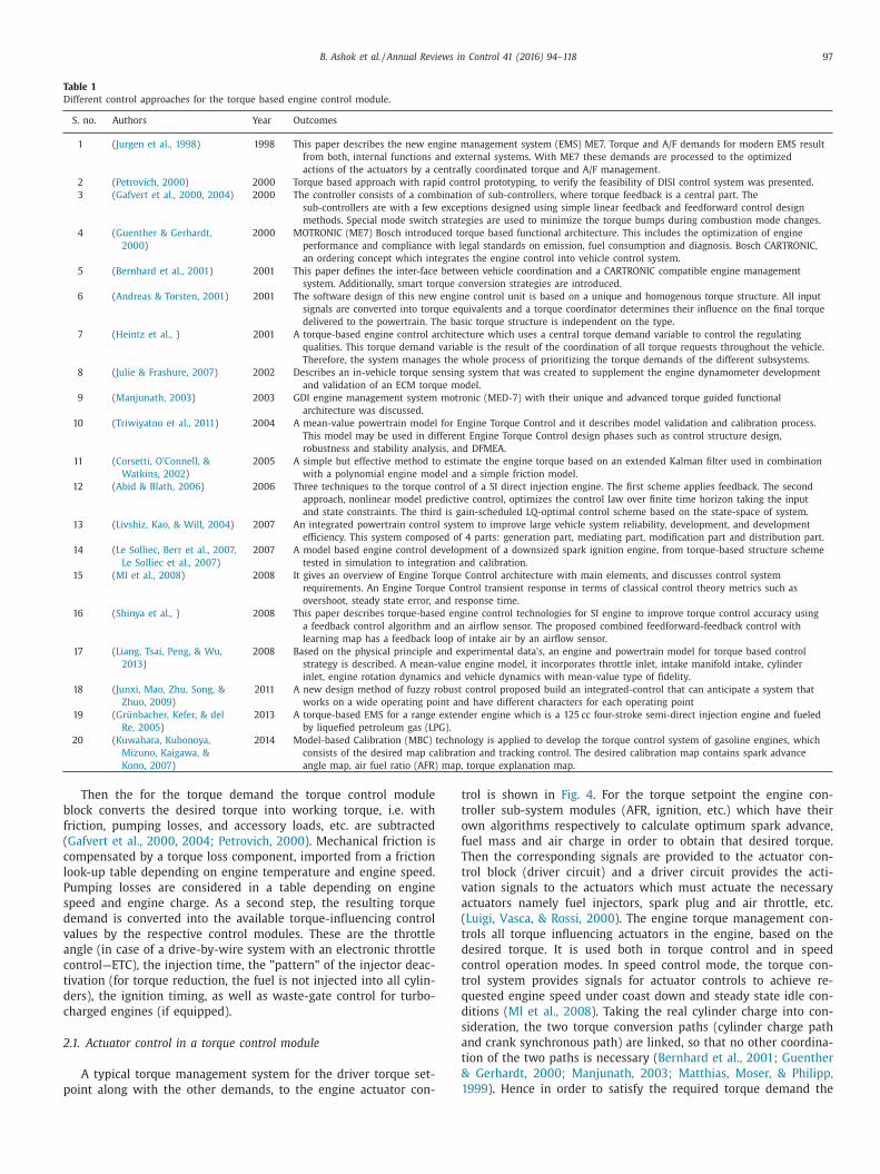
Fig. 6. Overall engine cylinder flow estimation scheme ( Alexander & Kolmanovsky,
2002 ).
a
i
s
e
s
c
3
j
i
a
i
i
r
i
s
p
m
d
n
t
b
fi
n
t
t
b
t
o
T
m
t
2
t
i
3
c
A
p
s
t
h
t
A
u
c
t
t
g
g
(
t
d
F
t
b
e
t
f
e
s
( Alexander & Kolmanovsky, 2002 ).
W cyl = ηv ηe
2
V d
p
RT (1)
Where W cyl is the mean value of the flow into the engine cylin-
ders, V d is the engine displacement and ηe is the engine speed; T
is the intake manifold temperature, p is the mean value of the in-
take manifold pressure and ηv is the volumetric efficiency of the
engine. This is done in the volumetric efficiency table or VE table
and needs to be mapped in the control unit during calibration. Tra-
ditionally the VE table is in 2D format, it has two axes, where one
is engine speed (RPM) and other is the manifold pressure. However
variations in the volumetric efficiency due to some factors such as
engine aging and wear, combustion chamber deposit buildup etc.,
can introduce errors in the air flow estimation.
In the MAF sensor type, air mass flow is directly measured
in the intake. Air flow measurement by means of a MAF sensor
(which is generally a hot wire anemometer) accurately estimates
the flow in the cylinder only in steady state, while in transient
state the intake manifold filling/empting dynamics play a signifi-
cant role ( Ferdinando & Lavorgna, 2006 ). Hence in MAF type air
flow measurement an input estimator can be used to correct the
air flow into the cylinder during both in transient and in steady
state operation. In general there are lots of approaches followed
for the estimator algorithm and in the following section we will
discuss one such approach developed by Stotsky and Kolmanovsky.
Input estimators are an important class of observer algorithms
aimed at estimating unmeasured inputs to dynamic systems from
state and output measurements. Practical issues such as the need
to deal with MAF sensor time constant and filter out periodic noise
at the engine firing frequency dictate that this input observer be
combined with additional filters into a larger estimation scheme
( Alain et al., 20 0 0 ; Grizzle et al., 1994 ). The resulting, overall es-
timation scheme shown in Fig. 6 , consists of three interconnected
observers and the approach uses the signals from the intake man-
ifold pressure sensor (in some system called as Boost Pressure
Sensor-BPS) and throttle mass flow. The first observer estimates
the flow through the throttle based on the signal from the MAF
sensor thereby compensating for the MAF sensor time constant.
The second observer estimates the intake manifold pressure using
the ideal gas law and the signal from the intake manifold pressure
sensor. This second observer is introduced to filter out the noise
nd periodic oscillations at the engine firing frequency contained
n the intake manifold pressure and throttle mass flow signals. This
econd observer is of a state estimation type as opposed to input
stimation type. The third observer is at the core of the estimation
cheme, and it is the one that provides an on-line correction to the
ylinder flow estimation ( Alexander & Kolmanovsky, 2002 ).
.2. Fuel film compensator
In the port fuel injection system, some of the fuel which is in-
ected at the intake port does not enter the cylinder immediately,
n fact, the fuel will impinge on the port walls, on the valve stem,
nd on the backside of the intake valve forming a fuel-film, caus-
ng a difference between the injected mass of fuel and that which
s inducted within the cylinder. A fraction of the injected fuel mass
emains vaporized and is mixed with the air before it is sucked
nto the combustion chamber. When this ‘fuel lag’ is not compen-
ated, there are significant spikes in the A/F ratio response. A com-
ensation action is therefore necessary to balance this fuel film
ass and it is accomplished by a model based approach. A model
escribing the fuel mass flow into the cylinders is necessary, since
ot all of the injected fuel mass is in gaseous form when the in-
ake valves opens. One of the most popular models describing the
ehavior of the fuel-film is the Aquino model; which is a simple
rst-order model and macroscopically tracks the liquid puddle dy-
amics inside the engine intake manifold. It has been widely used
o develop fuel-metering strategies, which compensate for the fuel
ransport lag. The fueling model estimates the fuel puddle mass
alance as a function of the injected fuel mass rate as the input
o the model and the liquid fuel flow into the cylinder as output
f the model ( Franchek Matthew et al., 2006; Roberto et al., 2005 ).
his fuel film compensator which is the part of AFR control module
odifies the quantity of injected fuel quantity in order to balance
he amount of fuel stored in and released by the film ( Alain et al.,
0 0 0 ). The fuel film compensator model may not be required for
he direct injection engine because of the fuel is injected directly
nside the combustion chamber.
.3. A/F ratio observer
The information required from the observer of a control loop
oncerns the air–fuel ratio in the individual cylinders. Most of the
FR observer approaches are based on the development of a sim-
lified model for exhaust transport delay, mixing phenomena, and
ensor dynamics. The transport delay mainly consists of two parts:
he cycle delay due to the four strokes of the engine and the ex-
aust gas transport delay caused by the exhaust gas flowing from
he exhaust valve to the tailpipe exhaust gas oxygen (EGO) sensor.
predetermined model or a time-delay look-up table (2D map) is
sed by the controller while computing the required time delay
ompensation. In addition, the time delay is largely dependent on
he engine operating condition defined by the engine speed and
he air mass flow. A 2D map yields the specific time-delay for any
iven combination of engine speed and load. Throughout the en-
ine operating envelope, the time delay can change significantly
Feng, Grigoriadis, Franchek, & Makki, 2006 ). In practice, the es-
imated time delay does not exactly match the actual total engine
elay ( Rajagopalan et al., 2014; Yildiray, 2009; Yildiray et al., 2008 ).
or engine transients, signal compensation is needed because of
he sensors finite time response, time delay and mixing behavior
etween the exhaust gases from the different cylinders ( Hajime
t al., 200 2; Tseng & Cheng, 1999 ). An observer is then applied to
he model, in order to perform real-time state estimation of air–
uel ratio, and many approaches have been followed, such as Lin-
ar Quadratic Gaussian, sliding mode control, Kalman filter, static
teady-state observer, nonlinear observer, etc. ( Bin et al., 2008 ).

B. Ashok et al. / Annual Reviews in Control 41 (2016) 94–118 101
Fig. 7. Controller with feedforward and feedback elements of the air fuel ratio module in SI engine.
i
h
t
d
E
a
a
s
c
c
b
3
g
t
s
w
j
a
s
T
m
fi
m
f
d
m
a
o
a
2
F
b
p
v
a
d
m
i
u
c
a
i
&
t
t
f
i
o
m
t
p
t
t
e
f
e
i
c
w
o
c
c
f
b
d
t
r
w
(
n
b
u
m
i
w
t
p
c
A
s
i
t
r
n
o
c
In order to construct an observer for the lambda control loop,
t is first necessary to model the dynamics of the injection to ex-
aust dynamics ( Per et al., 1998 ). In the AFR observer the informa-
ion sought is the fuel air equivalence ratio of the individual cylin-
ers. For this purpose the basic measurement is provided by the
GO sensor signal which is linear and the necessary compensation
ction will be carried out for the time delay, mixing phenomena
nd sensor characteristics by a proper model. The exhaust oxygen
ensor provides the information for close loop A/F ratio feedback
ontrol. This information is then converted into an injection time
orrection that is identical for all the engine cylinders, on a cycle-
y-cycle basis ( Al-Himyari et al., 2014; Nicolo et al., 2010 ).
.4. A/F ratio controller
Most of the current production AFR controllers are based on the
ain-scheduling approach to design feedforward and feedback con-
rol system by constructing lookup tables. The AFR module con-
ists of estimation of the air and fuel path dynamics combined
ith appropriate compensations. The controller calculates the in-
ector pulse width (IPW) based on air flow estimation, either by
manifold absolute pressure (MAP) or mass air flow (MAF) sen-
ors approach with respect to the driver demand and engine speed.
his predicted air mass is used to estimate the mass of fuel that
ust enter into the cylinder to achieve the air/fuel ratio speci-
ed in advance as per the driver torque demand. To deliver this
ass of fuel, a fueling path model based on injector characteristics,
uel puddling dynamics, fuel vaporization, and fuel entrainment
ynamics is used to estimate the needed injector pulse width com-
and ( Franchek Matthew et al., 2006; Winge et al., 1999 ). If the
ir-path model and fuel-path model are accurate, the application
f the feedforward fueling strategy will result in a stoichiometric
ir–fuel ratio during constant throttle operation ( Stroh David et al.,
001 ). A conventional air-to-fuel ratio control module as shown in
ig. 7 includes two nested control loop, a feedforward and feed-
ack control. The feedforward controller is tuned by means of ex-
erimental study during the calibration phase of the engine de-
elopment and obtained fuel injection map (lookup table) values
re stored in the memory of the controller. Generally, the proce-
ure of constructing the fuel injection map in the feedforward loop
eans the tuning of the feedforward controller for various operat-
ng conditions in order to obtain a final injection map. The look-
p tables is generated empirically for different engine operating
onditions and mappings are done for a large number of speeds
nd loads during calibration phase ( Seungbum et al., 2003; Dick-
nson, 2009; Rajagopalan, Stephen Yurkovich, Dudek, Guezennec,
Meyer, 2014; Tianyu, Haiqiao, & Zhao, 2011 ). In vehicle applica-
ions, the driver prescribes a torque demand to the control system
hrough the accelerator pedal. This information is directly trans-
ormed into AFR control module as desired air-mass set point, us-
ng a manifold model or a 2D look-up table.
Thus, feedforward loop generates a reference AFR value based
n the torque demand from the torque control module and by
eans of the controller the feedback loop maintains the air fuel ra-
io as close as possible to the desired AFR using the feedback out-
ut measured by the EGO sensor signal. The correction factor for
he feedforward controller is accomplished by the feedback con-
roller using the signal from EGO sensor. But in actual operation of
ngine, the transient condition tends to give an error in the feed-
orward controller due to modeling deficiencies, arising from say
nvironmental factors, variation in fuel composition, manufactur-
ng tolerances or mechanical wear. Thus the air/fuel ratio feedback
ontrol system compensates the unavoidable errors in the feedfor-
ard loop. Because the base fuel calculation has a tendency to drift
ff from the intended stoichiometric operating point and an active
losed loop lambda control is necessary to adjust the base fuel cal-
ulation ( Ohyama, 2001; Per et al., 1998 ). Feedforward control is
ast which may not be accurate and also handles the transients,
ut the feedback control- loop is slow, due to the feed gas oxygen
elay, but it ensures the required higher steady-state accuracy. For
he feedforward control loop the time-varying delay is the key pa-
ameter in the AFR control that imposes a limitation on the band-
idth of the AFR feedback loop by decreasing the phase margin
Ivan et al., 2006 ). In order to stabilize the unstable internal dy-
amics of the system and reduce the effect of unmatched distur-
ances on the steady-state tracking error, various controllers are
sed. Lot of approaches dealing with AFR prediction and control
ethods has been proposed which are listed in Table 2.
However, most of the controllers in production vehicle fuel-
njection systems consist of an open-loop feed-forward control
hich employs a look-up table and closed loop feedback con-
rol with PID, which works on the basis of a gain-scheduling ap-
roach. Due to their reliability and ease in implementation, PID
ontrollers are far most dominant control design approach for the
FR control applications in the vehicles. This is due to its simple
tructure and robust performance over a wide range of operat-
ng conditions. In addition the major advantage of the PID con-
roller over the other approaches is the familiarity of the algo-
ithm and the relatively few tuning parameters and also there is
o need of system model. These results in a significant reduction
n the tuning and calibration effort required to implement the
ontroller.

102 B. Ashok et al. / Annual Reviews in Control 41 (2016) 94–118
Table 2
Different controllers used in the air fuel ratio (AFR) module.
S. no. Controller used Authors Year Outcomes
for AFR module
1 PID ( Franceschi et al., 2007 ) 2007 Discrete, time-based, delay-compensated, adaptive PID control algorithm for AFR control is
employed.
( Kwiatkowski et al.,
2009 )
2009 Using a hybrid evolutionary-algebraic synthesis approach that combines LMI techniques based on
K-S iteration with evolutionary search, a scheduled PID controller is designed.
( Behrouz et al., 2012 ) 2012 A new synthesis method for AFR control by the time-varying delay in the system dynamics is first
approximated by Pade approximation with time-varying parameters. The associated error is then
utilized to construct a filtered PID controller combined with a parameter-varying dynamic
compensator.
( Guo et al., 2013 ) 2013 PID controller is aimed to track the given value of fuel injection quantity. Tuning controller
parameters are chosen by randomized algorithm according to the criteria of performance.
( Mayr Christian et al.,
2014 )
2014 New approach for automated calibration of nonlinear PID controllers and feedforward maps is
introduced. A dynamic local model network is used for actual physical process.
2 Adaptive control ( Tseng & Cheng, 1999 ) 1999 Adaptive AFR control scheme based on a one- parameter port fuel dynamics model with the
parameter being identified online.
( Stroh David et al.,
2001 )
2001 The steady-state adaptive fueling controller presented in this paper incorporates a modular model
structure which eliminates static maps and enables a plug and play feature for changes to the
sensor set.
( Yildiray et al., 2008 ) 2008 Two controllers for AFR, an Adaptive Feed-Forward Controller (AFFC) and an Adaptive Posicast
Controller (APC), have been developed and implemented in a vehicle.
( Rui et al., 2009 ) 2009 Nonlinear control approaches for multi-input multi-output (MIMO) engine models is developed, by
developing adaptive control and learning control methods.
( Yildiray et al., 2010 ) 2010 Two adaptive controller designs are considered. The designed AFR controller must reject
disturbances due to canister vapor purge and inaccuracies in air charge estimation and
wall-wetting compensation.
( Kahveci Nazli &
Jankovic, 2010 )
2010 An adaptive control structure which consists of an adaptive PI controller and an adaptive Smith
predictor for time-delay systems with unknown plant parameters
3 Neural network ( Seungbum et al., 2003 ) 2003 The control is based on the feedback error learning. The controller consists of Neural Network
(NN) with linear feedback. The NN are radial basis function network that are trained by using
the feedback error.
( Wang et al., 2005 ) 2005 Model predictive control (MPC) based on neural network model for air–fuel ratio, in which the
model is adapted on-line to cope with nonlinear dynamics and parameter uncertainties.
( Ivan et al., 2006 ) 2006 Recurrent Neural Networks for modeling and controlling AFR. The developed forward model used
to generate a reference AFR signal to train another RNN model aimed at simulating the inverse
AFR dynamics by evaluating the fuel injection time as function of AFR, manifold pressure and
engine speed.
( Zhai & Yu, 2009 ) 2009 MPC strategy is applied to air/fuel ratio control using neural network. The neural network uses
information from multivariable and considers dynamics to do multi-step ahead prediction.
( Zhai et al., 2011 ) 2011 MPC based on adaptive NN model attempted for AFR control. A Radial basis function (RBF)
network employed and recursive least squares (RLS) algorithm used for weight updating.
( Sardarmehni et al.,
2013 )
2013 MPC system is designed for robust control of lambda. Based on the simulation data, two neural
networks models of the engine are generated. The identified Multi- Layer Perceptron (MLP) NN
model yields small verification error compared with that of the adaptive Radial Base Function
(RBF).
4 Fuzzy logic ( Anurak & Sooraksa,
2012 )
2012 Improvement of mean value model (MVEM) and effective nonlinear control for the AFR regulator.
The regulator is designed by a discrete fuzzy PI algorithm, which provides easy tuning,
robustness.
( Farzin, Mansoorzadeh,
Zare, Shahryarzadeh,
& Akbari, 2013 )
2013 Approach for fuel control combines the design technique from variable structure controller is
based on Lyapunov& fuzzy estimator to estimate the nonlinearity of undefined dynamic in
backstepping controller
5 Model based methods
for non-linear control
( Roberto et al., 2005 ) 2005 Model-based AFR control technique is proposed: this is based on a dynamical model of the air
dynamics inside inlet manifolds and on the online identification of the fuel-film parameters.
( Bin et al., 2008 ) 2008 From multirate sampling method, control-oriented model, combining fuel delivery and exhaust gas
dynamics, is established. From estimated AFR, a decoupled PI compensator is designed.
( Shuntaro et al., 2009 ) 2009 The control consists of a feedforward control using a fuel behavior model, a feedback control using
an UEGO sensor and a feedback control HEGO sensor.
6 Sliding mode control
(SMC)
( Sei-Bum et al., 1994 ) 1994 An observer-based control algorithm based on sliding mode control technique is suggested for fast
response and small amplitude chattering of the air to- fuel ratio.
( Hajime et al., 200 2) 2002 SMC-based AFR feedback section with the oxygen storage mass predicting and controlling section
with a self tuning strategy.
7 Other controls in the
AFR module
( Holzmann et al., 1997 ) 1997 Neuro-fuzzy approach is discussed. For replacing 3D maps a modeling of engine characteristics for
vehicle control and simulation by multi-layer Perceptron and radial-basis function networks is
developed.
( Winge et al., 1999 ) 1999 A new lambda (normalized AFR) control methodology (H ∞ -control) which has a somewhat larger
bandwidth and guarantee robustness with respect to selected engine variable and parameter
variations.
( Alain et al., 20 0 0 ) 20 0 0 AFR control method with feedforward, feedback methods with the injector puddling models.
( Ferdinando &
Lavorgna, 2006 )
2006 Soft computing mass air flow estimator which is able to estimate, by using the combustion
pressure signal, the incoming mass air flow both in steady states and in transient conditions
( continued on next page )

B. Ashok et al. / Annual Reviews in Control 41 (2016) 94–118 103
Table 2 ( continued )
S. no. Controller used Authors Year Outcomes
for AFR module
( Franchek Matthew
et al., 2006 )
2006 The feedforward fueling control is separated into steady state and transient phenomena. Nonlinear
behavior associated with fueling is captured with nonlinear steady state models.
( Feng et al., 2006 ) 2006 An approach to combine an input shaping method together with a linear parameter varying (LPV)
feedback controller is proposed to solve the transient air–fuel ratio tracking problem.
( Dickinson, 2009 ) 2009 Systematic calibration of fuelling and speed controller. Non-linear black-box parameter directly
produces a dynamic inverse multivariable NARMA feedforward controller and linearizing
feedback compensator.
( Nicolo et al., 2010 ) 2010 A real time application of an original closed-loop individual cylinder AFR control system, based on
a spectral analysis of the lambda sensor signal is proposed.
( Gerasimov et al., 2011 ) 2011 Torque tracking and air-to-fuel ratio (AFR) stabilization at the stoichiometric level are addressed. A
data driven approach based on the design of direct and inverse models is proposed
( Rajagopalan et al.,
2014 )
2014 Control architecture for AFR control of designed to work with switching and/or wide range EGO
sensors, for minimizing calibration effort while meeting performance requirements.
( Efimov, Nikiforov, &
Javaherian, 2014 )
2014 The first control law is based on an a priori off-line identified engine model, while the second
control law is adaptive; it provides on-line adaptive adjustment to closed loop system. The
supervisor realizes a switching rule between these control laws providing better performance of
regulation.
Fig. 8. Schematic of electronic throttle in SI engine ( Conatser et al., 2004 ).
4
t
g
p
t
s
t
t
f
a
b
o
p
w
t
m
d
s
t
i
o
t
t
g
t
t
r
D
d
S
G
t
a
u
c
a
c
t
W
e
s
v
m
d
r
t
c
. Electronic throttle control (ETC) module
In the electronic fuel injection system of a SI engine, the throt-
le valve in the intake system controls the air flow into the en-
ine and thereby the cylinder charge, which determines the engine
ower and torque output. In conventional mechanical throttle ac-
uation technology (throttle body with stepper motor as an ‘idle
peed actuator’), the throttle valve assumed as a mechanical but-
erfly valve, is directly linked to the accelerator pedal. The air flow
hrough the throttle valve is therefore set by the driver and there-
ore operates the control device according to the need for power
nd torque. In this case, the control of the idle air control (IAC)
ypass valve which is typically very small using a stepper motor
r a solenoid is accomplished by the EMS.
The mechanical throttle system described above has been re-
laced by an electronic throttle control (ETC) as shown in Fig. 8
hich is also known as drive by wire (DBW) for a multitude of
echnical benefits. Thus in such systems accelerator pedal is not
echanically linked to the throttle device. It only facilitates the
river torque request from the engine through an accelerator pedal
ensor to the EMS. The principle of using a butterfly valve remains
he same; however a servo motor operates it. The throttle open-
ng angle is controlled by the engine management system, based
n the torque control module for the torque demand by the driver
hrough signals from the accelerator pedal sensor and other sys-
em requirements. In addition, a throttle position sensor is inte-
rated into the throttle device to give the actual position of the
hrottle valve. Based on this signal the closed loop control is main-
ained by the ETC control module to accomplish the throttle angle
equirement from the torque control module ( Christopher, 2012;
aniel, Nichols, & Schreurs, 20 0 0; Liang, Saikalis, McCune, De Rid-
er, & Lin, 200; Piero, Moro, Ponti, & Rizzoni, 1998; Stewart, 1998;
ood, Michael, & Michael, 2011; Suresh, Ganesan, Mallikarjuna, &
ovindarajan, 2013; Wengert, Dierk, & Ronny, 2007 ). Also, the elec-
ronic throttle body control offers the method to integrate ‘idle
ir control valve (IAC)’ and throttle plate regulation into a single
nit to control the angle of butterfly valve. But in case of the vehi-
les using mechanical throttle body (non ETC type) an idle speed
ctuator (stepper motor) which activates the air bypass valve cir-
uit, provides an airflow pathway around the closed throttle plate
o maintain the engine speed at idle ( Conatser, Wagner, Ganta, &
alker, 2004; Chris & Watson, 2003; Devor & Sun, 1997; Yildiz
t al., 2007 ).
As per the torque demand from the driver and other external
ystems (cruise control, traction control, etc.) the desired torque
alue is made as a setpoint for the engine by the torque control
odule. In order to obtain the torque demand the required cylin-
er charge has to be calculated initially and the resulting value
epresents the target cylinder charge which is necessary to realize
he demanded torque ( Jurgen et al., 1998 ).
For the indicated torque set point, trapped air mass and re-
irculated exhaust gas mass (if equipped) has to be considered.

104 B. Ashok et al. / Annual Reviews in Control 41 (2016) 94–118
Fig. 9. Air mass set point function of engine speed and torque set point ( Le Solliec,
Berr et al., 2007 ; Le Solliec et al., 2007 ).
t
t
c
t
t
i
t
t
m
p
f
t
f
&
s
t
t
c
T
a
s
n
s
w
1
s
s
e
l
m
t
b
a
t
e
f
t
t
r
a
5
e
Thus the air path control is split as the air mass control (throttle
valve and waste gate) and the re-circulated exhaust gas mass con-
trol. Based on the engine speed and torque demand setpoint, the
desired amount of air flow is calculated by a predetermined look-
up table as shown in Fig. 9 of 1.8 l Renault F5R engine which is
experimentally determined on a test bench, and that information
is used to calculate the target throttle position in order to achieve
the cylinder charge. For the required mass of air the target throttle
position can be determined based on a separate physical model of
intake manifold functions. In this case, an accurate model that can
describe the nonlinearity of the process is needed ( Ingram Grant,
Franchek, & Balakrishnan, 2003; Shinya et al., 2008 ). Then the in-
formation is transferred to the corresponding throttle actuator to
open the throttle valve angle independent from the position of the
accelerator by the electronic throttle control (ETC) module. For the
required air mass set point, the control commands are given to the
throttle actuator and waste gate actuator opening (if turbocharger
is equipped) ( Abid & Blath, 2006; Le Solliec, Berr et al., 2007;
Le Solliec et al., 2007; Paul, Zavala, & Fleming, 2005 ).However, it
is difficult to control the electronic throttle valve as there exists
some non- smooth nonlinearities, i.e., stick-slip friction, gear back-
lash, and a nonlinear spring for the limphome position ( Umit et al.,
2001 ).
A comprehensive ETC control module strategy usually consists
of a controller and nonlinear compensators that handle nonlin-
ear effects such as friction, and limp-home mode effects ( Chen
et al., 2010; Shugang et al., 2009 ).Thus, based on the throttle posi-
tion setpoint and the current throttle valve position measurement
Fig. 10. Electronic throttle control sy
hrough the position sensor along with the necessary compensa-
ions, the throttle control module determines the needed motor-
ontrol voltage with corresponding PWM signal. The electronic
hrottle consists of an H-bridge that receives PWM signals from
he controller. Based on the PWM signal duty cycle and direction
nformation from the controller, brushed DC motor and the gear
rain arrangements produce the required torque to move the throt-
le plate for the setpoint angle. For fail-safe reasons, the throttle
echanism contains two springs to positioning at a certain angle
osition to prevent the plate form completely. Such mechanical de-
ault throttle angle allows the engine to provide enough power for
he vehicle to “limp home mode (LH)” in the case of power supply
ailure ( Xiaofang & Wang, 2009; Di Bernardo et al., 2009; Toshihiro
Kowatari, 2001; Griffiths, 2002 ).
However, the electronic throttle control module performance is
ignificantly deteriorated in the small- signal operating mode due
o the servo motor drive train system friction and the dual re-
urn spring nonlinearity in the LH position. The slow response is a
onsequence of the stiction influences between the gear modules.
his friction occurs in the gearbox as well as in the throttle valve
nd motor shaft bearings. Similarly, a significant response delay (a
tandstill interval) appears while the throttle passes through the
onlinear LH region.
In order to improve the control system performance in the
mall-signal region operating mode, the controller is extended
ith necessary friction and LH compensators as shown in Fig.
0 ( Yang, 2004; Danijel et al., 2006 ). Thus the friction compen-
ator consists of a friction estimator which compensates for the
tatic and dynamic friction in the mathematical model [( Giulio
t al., 2013; Lars & Nielsen, 20 0 0 ), and ( Takeru et al., 2009 )]. Simi-
arly the spring nonlinearity at LH position is also compensated by
eans of a perfect spring model. Hence for the precise control of
hrottle opening by the ETC module, several control strategies have
een proposed as shown in Table 3.
From the table it is evident that among all of those methods,
daptive control using PID controller is widely used in the produc-
ion vehicle engine management system. This controlling method
nables high robustness and precise control performance. As the
riction and LH are the two nonlinearities affecting the stability of
he system was addressed with various approaches. Also the elec-
ronic throttle body is an electromechanical device which deterio-
ates in its performance due to wear and aging factors. In order to
ddress such factors a superior control system is needed.
. Idle speed control (ISC) module
The objective of the idle speed control module is to keep the
ngine speed close to the set point (selected target idle speed)
stem of a SI engine in an EMS.

B. Ashok et al. / Annual Reviews in Control 41 (2016) 94–118 105
Table 3
Different controllers used in the electronic throttle module.
S. no. Controller used Authors Year Outcomes
for ETC module
1 PID controller ( Jae & Byun, 1999 ) 1999 Throttle actuator for traction control system with a PID control to reduce the error is proposed.
( Yang, 2004 ) 2004 PID controller with friction shaker to cancel the friction leads to minimize the nonlinearity is
designed.
( Danijel et al.,
2006 ; Deur et al.,
2004 )
2006 Throttle control consisting of a PID controller with nonlinear friction and limp-home
compensators. Also the adaptive strategy consists of auto-tuning and self-tuning algorithms in
the throttle control.
( Shugang et al., 2009 ) 2009 Two-Degree-of-Freedom PID controller with Iterative Feedback Tuning (IFT) method is employed
for gain optimization.
( Andreas & Eriksson,
2009 )
2009 Static compensators to counter nonlinearities with a PID controller. IMC design is applied to
design the PD controller and a gain scheduled I-part is added for robustness against errors.
( Grepl & Lee, 2010 ) 2009 PID controller with nonlinear compensators for limphome and four different approaches for the
friction nonlinearity is proposed.
( Mercorelli, 2009 ) 2010 State observer for the Sensorless operation is developed. A real-time self-tuning of an
approximated proportional derivative (PD) regulator compensates tracking error caused by
inexact feedback.
( Chen et al., 2010 ) 2010 Two degree-of-freedom control system was designed, for nonlinear preload spring and disturbance
rejection against friction. The nonlinear behavior is verified using a simple PID control loop.
( Alt et al., 2010 ) 2010 Controller includes I-PD controller and a nonlinear control helps to compensate nonlinearities.
Control parameters are tuned automatically using an adaptive model based approach.
( Zeng & Wan, 2011 ) 2011 A nonlinear PID controller is proposed, it constantly adjusts the controller parameters proportional
gain -P, integral gain -I and differential gain -D with the system error changing.
( Thomasson & Eriksson,
2011 )
2011 Simultaneously active, static compensators to counter the nonlinearities. A PID controller is
designed for the linearized system, where pole placement is applied to design the PD controller
and a gain scheduled I-part is added for robustness against model errors.
( Al-samarraie & Abbas,
2012 )
2012 Proposed control law replaces the integral of the conventional PID controller by an integral term
that uses the arc tan function for the error instead of the linear error function.
2 Adaptive control ( Eiji et al., 2003 ) 2003 To attain robustness, an adaptive control system has been constructed using sliding mode control
and includes an identifier for sequential calculations in the throttle control.
( Di Bernardo et al.,
2009 )
2009 Model reference adaptive algorithm, LQ-MCS: Linear Quadratic-Minimal Control Synthesis. The
feature of this controller is that minimal synthesis is needed to implement the strategy.
( Giulio et al., 2013 ) 2012 Friction phenomena are expected to be time-varying; an adaptive extension of the controller is
proposed and validated for motorcycle.
3 Fuzzy logic ( Chen & Ran, 2009 ) 2009 A fuzzy immune adaptive PID control based on immune feedback is proposed for electronic
throttle.
( Wang et al., 2010 ) 2010 Fuzzy-PID was modeled for controller; simulation was accomplished during the transient
condition.
( Chen et al., 2012 ) 2012 Adaptive fuzzy logic based sliding mode controller to enhance the control strategy robustness with
respect to parameter variations and external disturbances for electronic throttle.
( Wang & Huang, 2013 ) 2013 Nonlinear hysteretic adopted for electronic throttle. A new closed-loop back-propagation tuning is
proposed for tuning of fuzzy output membership functions to yield better tracking.
5 Model based methods ( Lars & Nielsen, 20 0 0 ) 20 0 0 The model-based controller is designed to compensate for the friction present in the system as
well as the varying torque that comes from the air flow past the throttle plate.
( Montanaro et al.,
2014 )
2007 Model predictive control (MPC) strategy is derived for the electronic throttle with the procedure is
proposed to model friction in a discrete-time piecewise affine (PWA).
(Yuan and Wang, 2009) 2009 Approximate model-based robust nonlinear control (AMRNC) for uncertainty compensation is
proposed
( Nakano et al., 2006 ) 2014 Model reference adaptive control (MRAC) method is designed and tested on 2-L engine to provide
the robust handling of nonlinear torques acting on the plant due to limphome.
6 Sliding mode control ( Umit et al., 2001 ) 2001 The discrete-time sliding mode controller together with the sliding mode observer is designed to
realize the robust tracking control.
( Aono & Kowatari,
2006 )
2006 Observer-based sliding-mode controller with prescribed transient response is designed for the
system.
7 Other controls ( Paul et al., 2005 ) 2004 A pole placement controller by the multiobjective optimization technique with the objective of
reducing or eliminating the oscillatory response is designed.
( Yuan et al., 2008 ) 2006 Throttle-control algorithm for improving engine response is proposed. This algorithm compensates
the two delays based on the delay in the throttle response and manifold filling.
( Feru et al., 2012 ) 2008 Support vector machine (SVM)-based approximate model control for the electronic throttle. The
nonlinear control derived based on Taylor expansion, which avoids not only complex control
development and intensive computation but also online learning or adjustment.
(Feru et al., 2012) 2012 Lyapunov-based control using for throttle and cam timing to reduce exhaust emissions is proposed.
( Thornhill & Sindano,
20 0 0 )
2014 Mixed constrained H 2 /H ∞ LPV controller was designed for the LPV throttle control system using
the linear matrix inequality convex optimization approach.
( Yurkovich & Li, 2005 ) 2014 Discrete-time gain-scheduling H 2 controller is designed for an electronic throttle system based
upon the LMI (linear matrix equality) convex optimization scheme.
a
l
d
e
p
c
&
o
o
s
e
t
a
nd at the same time prevent engine stalling when disturbance
oads are applied or removed. The torque disturbances are mainly
ue to the intermittent use of devices powered by the engine, for
xample headlamp, air conditioning compressors, power steering
umps, electric windows and battery charging and other electri-
al accessories that affect the engine speed at idle mode ( Howell
Best, 20 0 0 ). The idle speed system with its physical inputs and
utputs are represented in Fig. 11 , which shows that the controller
nly has control over the fuel, air, re-circulated exhaust gas and
park timing. The other factors affecting the idle engine speed are
ither part of the engine design or function of atmospheric condi-
ions ( Yurkovich & Li, 2005 ).
Smooth transitions from higher engine speeds to idle speed are
lso required to increase drivability. Factors that most affect the

106 B. Ashok et al. / Annual Reviews in Control 41 (2016) 94–118
Fig. 11. Inputs, outputs and disturbances to the idle speed system ( Yurkovich & Li, 2005 ).
i
s
l
a
T
a
t
o
t
t
j
S
h
F
i
m
t
S
i
i
t
t
e
t
t
s
v
t
l
c
v
I
i
o
n
e
m
d
s
t
c
a
t
i
idle speed are the intake-airflow and the ignition timing ( Christian,
Bohme, Staate, & Manemann, 2006 ). The spark advance and the
throttle which controls the mixture mass (cylinder filling factor)
are used to control the engine speed. Idle speed regulation is made
with these two main actions. One is control by the intake air flow
(throttle angle) and other is the control of spark advance for fast
torque response in some cases ( Luigi et al., 1999; Manivannan,
2011; Scillieri, 2002; Stefan & Eriksson, 2006 ). One of the aspects
to be taken into account is that, the control action using the spark
advance path is faster than using the air-channel. Hence the typical
idle speed module utilizes two control paths for the controller ac-
tion. It first uses the spark advance as the main control input and
afterward, as soon as the engine speed is taken care of by the air
input, the spark advance should go back to its nominal value. In
other words, the spark advance should exert its fast action mainly
during the first part of the transient phase ( Jacek, 2010 ). In most
cases, both of them are used in parallel. The two control signals
should be aware of each other and the relative spark advance has
to converge to a desired setpoint value. Thus for the changes in ad-
ditional loads, idle speed control is accomplished by the mixture
mass to reach the cylinder that is being adjusted. If the changes
are smaller and quick response is required, control is executed by
adjusting spark advance ( Stefan & Eriksson, 2006 ).
The idle speed setpoint depends on the various torque distur-
bances to the engine during idling mode. But the load torque is
not actually measurable, only predictable through the feedforward
lookup tables of the various disturbances, since the ECU knows the
accessories are switched on ( Jingshun & Kurihara, 2003 ). There is
a feedforward controller consist of multiple lookup tables which
might, predict the loads due to accessories for different operating
conditions. By estimating the load torque presented to the engine
by the measured disturbance one can calculate, for fixed A/F ratio
and spark, the amount of air that is needed to maintain the engine
speed at the fixed setpoint. A closed loop controller determines the
compensation with throttle and ignition actuators for the engine
speed tracking error and is typically gain-scheduled on operating
conditions where nonlinear maps are used to determine the gains
( di Gaeta et al., 2010; Yildiz et al., 2007 ).
While designing the idle speed control module the main
complexity that needs to be handled is the control process of
induction-to-torque delay in the engine ( Christian et al., 2006 ).
This dead time in the process of intake air control is one of the
reasons that cause the worse response and poor stability of idle
speed control. Thus the response and stability is to be improved
because of combustion delay, passage delay, speed detection de-
lay, torque disturbance, electricity load and other related problems
n an intake air control system ( Luigi et al., 1999 ). Hence, the idle
peed control loop should compensate for these kinds of time de-
ays in the process and other related effects, either by an appropri-
te compensated model or by feedforward methods ( Jacek, 2010 ).
his problem is typically addressed by combining some form of
feedforward control with a closed-loop compensation based on
he engine speed error. If the speed error goes beyond the thresh-
ld range, ECU regulate idle valve through the stepper motor posi-
ion in case of mechanical throttle system, (whereas in electronic
hrottle control the servo motor adjust the butterfly valve) to ad-
ust intake mass flow to maintain the desired crankshaft speed ( Le
olliec, Berr, et al., 2007; Chamaillard et al., 2004; Jingshun & Kuri-
ara, 2003 ). Hence, the typical idle peed control module shown in
ig. 12 consists of time delay compensators, load estimators for the
dle speed setpoint based on the load torque and a controller to
aintain the idle speed setpoint.
The controller provides the reference throttle angle ( θreq) to
he throttle control module based on the idle speed setpoint ( ωIdle
peed) by considering the different load torque requirements. Sim-
larly the spark control loop provides the spark angle based on the
dle setpoint ( Jacek, 2010; Yildiray et al., 2011 ).If the error deriva-
ive exceeds pre-defined thresholds, control is activated on both
hrottle angle and spark advance values; otherwise the control is
nabled only on spark advance values. Such choice is mainly due
o two reasons: the large amount of engine torque variation con-
ained in the range of spark advance angle and manifold pressure
hows the better torque difference. If both the controls are acti-
ated, the first new throttle angle value is held constant for a cer-
ain time interval, while the error (residual or due to an unknown
oad) is compensated by new spark angle values. A so-called syn-
hronization function of the controller verifies if the spark angle
alues fall within an interval centered on the nominal angle value.
f this condition is not matched for a certain number of comput-
ng steps, the ISC actuates the throttle, by varying their positions
f pre-defined increments. Spark advance is then restored to its
ominal value ( Singh et al., 2002; Subramaniam et al., 2002 ). Sev-
ral possible controllers are employed for the idle speed control
odules are listed in Table 4.
Over the years different closed loop idle speed control system
esigns have been adapted in the literature. However there is a
cope for providing a superior performance in the idle speed con-
rol module by tackling the time delay factor, changes in operating
onditions and aging of the components by providing an adaptive
lgorithm. Also in order to meet the emission targets, by adapting
he start stop system in the engine during idling mode can also be
mproved by the robust control system design.

B. Ashok et al. / Annual Reviews in Control 41 (2016) 94–118 107
Fig. 12. Idle speed control module of a SI engine.
Fig. 13. Ignition angle and other relevant outputs in the torque structure ( Andreas & Torsten, 2001 ).
6
m
s
s
n
t
p
e
o
d
c
W
c
a
a
v
s
t
l
a
t
s
s
T
E
s
l
o
c
t
b
t
c
t
i
w
t
c
fl
e
t
a
F
t
t
l
b
. Ignition control module
In the torque control structure of an SI engine, for the de-
anded torque, control signals are fed into the actuating paths
uch as throttle control, injection timing and ignition timing as
hown in Fig. 13 . The superior ignition timing determines the sig-
ificant quality and efficiency output from the engine. The ignition
iming is evaluated based on the set value of the torque and other
arameters like engine speed and actual engine air flow ( Gafvert
t al., 2004 ).
The ignition control module varies its operation for different
perating modes such as idling, cranking, overrun and normal con-
itions. During idling, the ECU controls the ignition advance ac-
ording to engine idle speed setpoint and coolant temperature.
hen cranking the engine, the ignition signal is produced by the
rankshaft position signal for a pre-set value of ignition advance
nd similarly during the over speed the ignition angle advance for
pre-set value, in order to limit the engine speed. These pre-set
alues are obtained during the calibration for cranking and over
peed protection separately, and stored in the controller. During
he normal condition, the ignition advance is controlled in open-
oop or closed-loop mode ( Zhengmao, 2001 ).
Thus, in the transient operating conditions open-loop control is
dopted for fast response and in the steady or higher load condi-
ions closed loop control is followed, based on the knock feedback
ignal the ignition advanced angle is corrected. Some of the re-
earch works carried on the Ignition control module are listed in
able 5.
The two ways by which ignition timing is controlled in an
MS, are open-loop control and closed-loop control. The open-loop
cheme for the ignition timing control relies on pre-determined
ook-up tables. The base ignition timing is stored in the memory
f the controller which acts as a feedforward controller. Open-loop
ontrol is a scheduled program control where a table-based igni-
ion strategy is used, which generates the optimized spark angle
ased on the current engine working point. A first optimization
akes place during the calibration phase (experiments on engine or
hassis dynamometers) of the engine development process to ob-
ain the values of the best ignition advance angle of various work-
ng conditions. These values have been stored in the ECU as a table,
hich are called the basic ignition advanced angle map. In order
o determine the required values of ignition timing for achieving a
ertain torque demand by the ignition control loop, the mass air
ow, engine temperature, speed and other related signals from the
ngine has to be known. During the operation of the engine, for
he corresponding engine speed and load, the ignition advanced
ngle is determined from the map (lookup table) as shown in
ig. 14 , from the EMS. Thus, by means of the feedforward con-
roller the nominal ignition angles (realizing maximum brake
orque while avoiding knock and excessive engine-out pollution
evels) depending on the engine speed and load (as measured
y manifold pressure or other related signals) is obtained. This

108 B. Ashok et al. / Annual Reviews in Control 41 (2016) 94–118
Table 4
Different controllers used in the idle speed control (ISC) module.
S. no. Controller used Authors Year Outcomes
for ETC module
1 PID controller ( Howell & Best, 20 0 0 ) 20 0 0 Tuning process of PID is automated through the use of continuous action reinforcement learning
automata. These are used to simultaneously tune the parameters of a three term controller
on-line.
( Chamaillard et al.,
2004 )
2001 A PID controller is used for idle speed control for a torque based engine control. The controller
output delivers the required torque demand component to keep the engine speed on the
setpoint.
( Jacek, 2010 ) 2004 Analytical design method of tuning PI and PID idle speed controllers is proposed. The method
based on damping optimum criterion. Design of advanced, polynomial speed controller is also
presented.
( Luigi et al., 1999 ) 2006 A model-based control method for idle speed of spark-ignition (SI) engines. It is based on
mid-ranging, a multivariable control strategy that is more commonly used in process control.
The basic building blocks of the control structure are two PI controllers.
( Jingshun & Kurihara,
2003 )
2010 Idle speed control for GDI engines have been tackled and solved via a gain scheduling PID strategy
in conjunction with an AFR dynamics compensator.
( Scillieri, 2002 ) 2011 The simple idle speed model developed in this work was found to be effective in determining a
set of PID control parameters that are similar to the best values obtained using experiments.
2 Adaptive control ( Josko et al., 2004 ) 2006 A Map-based injection, oxygen feedback and adaptive PID controller are combined to form a quick
and low-cost air–fuel ratio control system, by which a low steady Idle-speed is realized on SI
engine.
( Yildiz et al., 2007 ; di
Gaeta et al., 2010 )
2007 Adaptive Posicast Controller for time-delay systems to the idle speed control (ISC) problem in IC
engines. It regulates the engine speed at a prescribed set-point in the presence of accessory load
torque.
( Kong et al., 2006 ) 2007 An adaptive multi-input single-output (MISO) controller based on self-tuning regulator. The
Recursive Least Square technique is employed to identify the engine as a first-order MISO linear
model. Pole placement technique is then used to design the adaptive MISO controller.
( Yildiray & Anuradha,
2011 )
2009 Torque estimator based on an adaptive Kalman filter. The estimator is used to establish a fast load
torque compensation path within a PI controller-based idle speed control system.
3 Neural network ( Stefan & Eriksson,
2006 )
2010 Algorithm of idle speed stabilization in the SI engine by means of spark advance control. The
algorithm is based on a well-known approach of a model-based adaptive control and uses
artificial neural networks model observer of the additional effective torque.
4 Fuzzy logic ( Feng-Chi et al., 2007 ) 2002 Analytically developed fuzzy control law can be used in practical application such as the idle
speed control problem provided that certain modifications and assumptions are taken into
consideration in the derivation and the application of the control law.
( Danijel et al., 2009 ) 2002 Two control variables one controlling the air by-pass valve and other the timing of the spark that
differ sensibly in both their quantitative and temporal effectiveness are addressed SI engine
model.
5 Model based methods ( Chris & Watson, 2003) – Proposed ISC consisting of decoupled manifold pressure and spark retard control loops. Controller
incorporates a model predictive element in the selection of the bypass valve duty cycle, which is
used to set the intake manifold pressure.
( Subramaniam et al.,
2002 )
2003 A model-based approach to idle speed control design has been presented. Further developments
concern a smoother transition from ISC to other model-based strategies (torque-based engine
control, for example), and also the analysis of engine management strategies for the cranking
phase
( Singh et al., 2002 ) 2010 Model-based control scheme to the cold-start speed control in SI engine. The multi-variable
control algorithm is developed with the purpose of improving the transient performance of the
starting speed.
6 Other controls ( Jacek, 2010 ) 1999 Idle-speed control designed through optimal LQ technique taking into account during the design
phase the presence of finite time delay between variations of manifold pressure and the
produced torque.
( Luigi et al., 1999 ) 2003 Dead time compensation for intake air control is by adopting a Smith predictor combining with
disturbance compensator to improve the idle speed control system’s response to the disturbance.
( Nicolo et al., 2003 ) 2003 A directly identified non-linear inverse-NARMA compensation methodology for stable systems has
applied to the dynamics of SI engine for the idle-speed regulation robust control problem.
( Christian et al., 2006 ) 2005 Sliding mode Control method was applied to the IC engine idle speed control, not for stabilization
(because the engine is stable itself during idling) but for compensation with the effects of the
delay.
( Manivannan, 2011 ) 2006 Nonlinear engine model for idle speed controllers is described. The suitability of model has been
shown through a straightforward MIMO H ∞ design using the torque reserve as an additional
output
( Jiangyan et al., 2010 ) 2007 A new concept for idle speed control is designed. This control is based on a two degree-
Of-freedom sliding mode algorithm. It controls engine speed by altering both the valve lift and
the ignition timing.
t
f
e
i
t
a
correlation is static and is only optimal for that engine from which
the ignition data was obtained during the calibration of the ECU
( Arno et al., 2012; Baitao et al., 2013; Bhot & Quayle, 1982; En-
rico et al., 2014; Eriksson & Nielsen, 1997; Guzzella & Onder, 2010;
Huang & Chen, 2006; Kosuke, Yasui, & Sato, 2007; Masatake et al.,
2001; Molina, Barros, Baeta, & Fabricio, 2004; Petridis & Shenton,
2003; Pacheco et al., 2004; Saravana Prabu & Naiju, 2009 ).
Ignition timing that arrives from the feedforward controller has
o be finalized based on considering the some of the correction
actors. One of such correction is based on the temperature of the
ngine coolant to arrive at the final ignition advanced angle and
s shown in Fig. 15 . Thus by using the ignition control loop for
he measured engine speed and the relative load, a nominal spark
dvance angle is selected (block “map1” in Fig. 14 ). A simplified
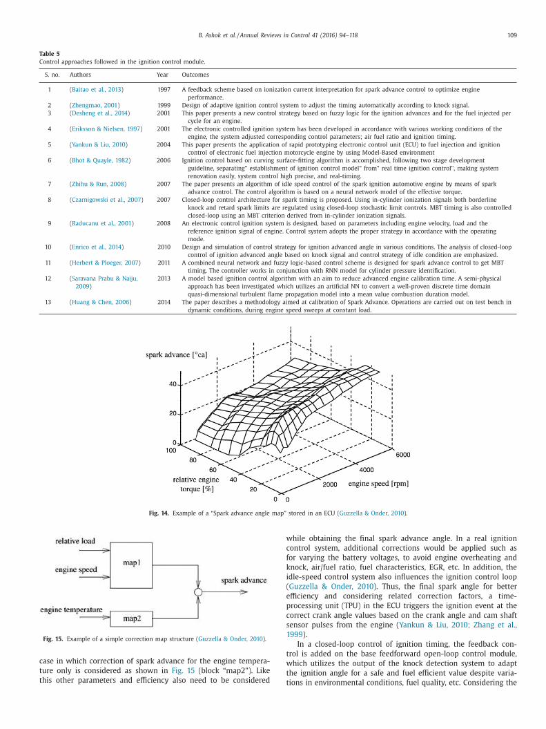
B. Ashok et al. / Annual Reviews in Control 41 (2016) 94–118 109
Table 5
Control approaches followed in the ignition control module.
S. no. Authors Year Outcomes
1 ( Baitao et al., 2013 ) 1997 A feedback scheme based on ionization current interpretation for spark advance control to optimize engine
performance.
2 ( Zhengmao, 2001 ) 1999 Design of adaptive ignition control system to adjust the timing automatically according to knock signal.
3 ( Desheng et al., 2014 ) 2001 This paper presents a new control strategy based on fuzzy logic for the ignition advances and for the fuel injected per
cycle for an engine.
4 ( Eriksson & Nielsen, 1997 ) 2001 The electronic controlled ignition system has been developed in accordance with various working conditions of the
engine, the system adjusted corresponding control parameters; air fuel ratio and ignition timing.
5 ( Yankun & Liu, 2010 ) 2004 This paper presents the application of rapid prototyping electronic control unit (ECU) to fuel injection and ignition
control of electronic fuel injection motorcycle engine by using Model-Based environment
6 ( Bhot & Quayle, 1982 ) 2006 Ignition control based on curving surface-fitting algorithm is accomplished, following two stage development
guideline, separating" establishment of ignition control model" from" real time ignition control", making system
renovation easily, system control high precise, and real-timing.
7 ( Zhihu & Run, 2008 ) 2007 The paper presents an algorithm of idle speed control of the spark ignition automotive engine by means of spark
advance control. The control algorithm is based on a neural network model of the effective torque.
8 ( Czarnigowski et al., 2007 ) 2007 Closed-loop control architecture for spark timing is proposed. Using in-cylinder ionization signals both borderline
knock and retard spark limits are regulated using closed-loop stochastic limit controls. MBT timing is also controlled
closed-loop using an MBT criterion derived from in-cylinder ionization signals.
9 ( Raducanu et al., 2001 ) 2008 An electronic control ignition system is designed, based on parameters including engine velocity, load and the
reference ignition signal of engine. Control system adopts the proper strategy in accordance with the operating
mode.
10 ( Enrico et al., 2014 ) 2010 Design and simulation of control strategy for ignition advanced angle in various conditions. The analysis of closed-loop
control of ignition advanced angle based on knock signal and control strategy of idle condition are emphasized.
11 ( Herbert & Ploeger, 2007 ) 2011 A combined neural network and fuzzy logic-based control scheme is designed for spark advance control to get MBT
timing. The controller works in conjunction with RNN model for cylinder pressure identification.
12 ( Saravana Prabu & Naiju,
2009 )
2013 A model based ignition control algorithm with an aim to reduce advanced engine calibration time. A semi-physical
approach has been investigated which utilizes an artificial NN to convert a well-proven discrete time domain
quasi-dimensional turbulent flame propagation model into a mean value combustion duration model.
13 ( Huang & Chen, 2006 ) 2014 The paper describes a methodology aimed at calibration of Spark Advance. Operations are carried out on test bench in
dynamic conditions, during engine speed sweeps at constant load.
Fig. 14. Example of a “Spark advance angle map” stored in an ECU ( Guzzella & Onder, 2010 ).
Fig. 15. Example of a simple correction map structure ( Guzzella & Onder, 2010 ).
c
t
t
w
c
f
k
i
(
e
p
c
s
1
t
w
t
ase in which correction of spark advance for the engine tempera-
ure only is considered as shown in Fig. 15 (block “map2”). Like
his other parameters and efficiency also need to be considered
thile obtaining the final spark advance angle. In a real ignition
ontrol system, additional corrections would be applied such as
or varying the battery voltages, to avoid engine overheating and
nock, air/fuel ratio, fuel characteristics, EGR, etc. In addition, the
dle-speed control system also influences the ignition control loop
Guzzella & Onder, 2010 ). Thus, the final spark angle for better
fficiency and considering related correction factors, a time-
rocessing unit (TPU) in the ECU triggers the ignition event at the
orrect crank angle values based on the crank angle and cam shaft
ensor pulses from the engine ( Yankun & Liu, 2010; Zhang et al.,
999 ).
In a closed-loop control of ignition timing, the feedback con-
rol is added on the base feedforward open-loop control module,
hich utilizes the output of the knock detection system to adapt
he ignition angle for a safe and fuel efficient value despite varia-
ions in environmental conditions, fuel quality, etc. Considering the

110 B. Ashok et al. / Annual Reviews in Control 41 (2016) 94–118
Fig. 16. Knock detection system based on band-pass filter ( Haoyun et al., 2013 ).
q
a
s
d
i
K
&
G
i
p
t
o
t
n
&
7
a
i
i
i
t
t
p
c
&
f
b
s
l
e
k
o
i
T
i
k
c
c
t
d
i
k
t
b
l
l
i
S
o
control cost and accuracy, open-loop control combined with
closed-loop control are adopted in the control system in order to
achieve faster response and better control accuracy ( Guzzella &
Onder, 2010; Enrico et al., 2014 ). In the closed-loop control, the
knock sensor signal is selected as the feedback signal to keep the
ignition advanced angle around the critical knocking point ( Cui,
2008 ). In the next section we will discuss knock detection and con-
trol strategy.
7. Knock detection and control module
Advancing the ignition timing by the ignition control module in
the torque structure is one of the important factors for maximiz-
ing the output torque and the fuel economy of an engine. Unfor-
tunately, the optimum spark timing is often accompanied by the
occurrence of knock in the combustion, and even leads to dam-
age to the engine in extreme conditions. Therefore, a trade-off is
necessary in engine control between; maximizing the spark ad-
vance and avoiding the occurrence of engine knock ( Go-Long et al.,
2004 ). Most commonly, knock is defined to occur when it is audi-
ble. Knock sensing plays an important role in knock control. Hence
the knock control module consists of knock detection and con-
troller for controlling the knock phenomena. The majority of con-
trol algorithms therefore detect the resulting knock in the combus-
tion chamber by means of different techniques. Many approaches
have been applied to detect the knock, and each has its own mer-
its. Commonly techniques applied to knock detection include ei-
ther in-cylinder pressure transducers, engine block mounted ac-
celerometers or ionization signal form the combustion. Knock de-
tection based on in-cylinder pressure transducers is very effec-
tive but these sensors are expensive for the production engines
( Herbert & Ploeger, 2007 ). Hence the dedicated knock sensors, ba-
sically a piezoelectric acceleration sensor attached to the engine
block is used in production vehicles. Typically, one or two sensors
are used depending on the application (e.g., one sensor per bank
on a ‘V’ block engine; one sensor for an ‘in-line’ block). The funda-
mental role of the knock sensor is to extract a feature characteristic
of knock that allows discrimination between normal engine noises
and knock ( Haoyun, Yang, Shen, & Peyton Jones, 2013 ).
7.1. Knock detection
A knock control module consists of a separate signal detec-
tion unit to spot the knock from the accelerometer sensor signal
as shown in Fig. 16 , which is composed of three main elements:
knock sensors, knock detector and control strategy executing on
the controller. The traditional approach for knock detection sys-
tem uses a band-pass filter, and recognizes the frequency band
of the knocking from the normal noises of combustion and fric-
tion. Hence, the output of the accelerometer sensor passes through
a band-pass filter which selects the most representative resonant
frequency components of the knock signal. The resonance fre-
uency depends on the dimensions of the combustion chamber
nd on sound velocity of the cylinder charge. The resulting output
ignal is then integrated and compared over the crank-angle win-
ow where knock is expected to occur, in order to obtain knock
ntensity ( Flolka, 2006; John, Keane, Koseluk, & Whitlock, 1998;
aneyasu, Kurihara, Katogi, & Tabuchi, 1995; Peyton Jones, Spelina,
Frey, 2013; Samir, Agarwal, & Chand, 2011; Stefan, Rychetsky,
lesner, & Groppo, 1997 ). For every cycle of any cylinder, the max-
mum amplitude of the band pass-filtered signal is calculated and
assed to the knock controller. Knocking cycles are identified by
he peak value of the band-pass filtered sensor signal. The thresh-
ld for defining a cycle as knocking is set as a preset value during
he calibration. The peak amplitude of the band pass filtered sig-
al is used as individual cycle knock intensity (KI) ( Timo, Schuerg,
Kempf, 2012; Zhu Guoming, Haskara, & Winkelman, 2005 ).
.2. Knock control system
To limit the knock when it is detected, commonly used control
pproaches are retarding the spark timing or by reducing the load,
.e., closing of the intake throttle or by controlling the waste gate
n the case of turbocharged engines(if equipped). Load reduction
s used only if knock cannot be suppressed by delaying the igni-
ion angle. Thus, knock control mostly is accomplished by changing
he ignition timing in the consecutive cycle itself. This is accom-
lished by changing the ignition timing in the next power stroke
ycle itself, which leads to reduce the knock ( Piernikarski, Hunicz,
Komsta, 2013 ).Thus a knock control module consists of a feed-
orward open loop in order to determine the base spark timing
ased on the engine operation conditions and, a feedback control
ystem which has knock detection and a control unit.
A knock control module of a SI engine consists of feedforward
ookup table of the ignition timing and a closed-loop control strat-
gy for ignition timing correction based on feedback from the
nock sensor signal as shown in Fig. 17 . The closed loop correction
f ignition timing controls the knock by adjusting the spark tim-
ng in order to optimize the engine operation and prevent damage.
he knock controller determines the corrected spark timing which
s the sum of the base spark timing obtained from the map. The
nock controller uses the knock intensity (KI) as an input signal to
ontrol the ignition timing so that a certain knock rate will not ex-
eed the threshold limit. When the cycle knock intensity exceeds
he threshold value, the ignition timing for the considered cylin-
er is retarded by a certain angle. Afterward, the ignition angle
s advanced again at the rate of 10 CA per second as long as the
nock amplitude remains lower than the threshold. Thus, the igni-
ion correction is subtracted from the nominal ignition angle given
y the feedforward ignition controller. Hence, the knock control
oop results in the operation of ignition angles closer to the knock
imit and hence higher compression ratios can be implemented to
ncrease the thermodynamic efficiency of the engine ( Lonari, 2011;
iano & Bozza, 2013 ). Waste gate control is also employed in case
f the turbocharged engine which is another possibility of reducing

B. Ashok et al. / Annual Reviews in Control 41 (2016) 94–118 111
Fig. 17. Knock control strategy based on ignition control ( Enrico et al., 2014 ).
t
T
b
p
r
6
e
i
k
e
a
o
o
8
m
t
s
a
e
u
J
a
b
i
o
t
a
o
r
f
i
i
s
n
r
b
d
i
s
c
o
t
F
2
C
m
&
8
c
s
o
s
c
c
e
c
t
s
i
t
p
i
b
T
t
t
e
b
n
i
T
t
he engine’s susceptibility to knock by cooling the cylinder charge.
his can be achieved by either cooling the aspirated air (in tur-
ocharged systems, often an intercooler is applied after the com-
ressor anyway) or by fuel enrichment, i.e., driving at air-to-fuel
atios lower than stoichiometric ( Guzzella & Onder, 2010 ).
The various controllers used for knock control are listed in Table
. All these controllers have common control objectives, the strat-
gy by which the objectives are achieved can be varied signif-
cantly. Most production knock control modules use a standard
nock control strategy where control movements are executed for
ach step. The magnitudes of these control moves are also fixed,
dvancing the spark by a small amount, whenever knock does not
ccur, or retarding by a much larger amount, if in fact knock does
ccur.
. Diagnostics module
In order to regulate a superior engine system performance,
ore and more feedback control loops with embedded sensors, ac-
uators and controllers are integrated in the engine management
ystems. Hence an increase in the complexity of engine systems
nd increased dependence on electronic engine controls leads to
mbedded fault detection and diagnosis as an indispensable mod-
le in the engine management systems. ( Kjellqvist, 2005; Spelina
ill, Jones, & Frey, 2014 ).The diagnostic module in the EMS is to
lert the driver if a system behavior diverges from the expected
ehavior, by means of a malfunction indicator lamp (MIL) in the
nstrument cluster. The need for failure diagnostics in automobiles
riginates from two perspectives: a maintenance-oriented perspec-
ive and a safety-oriented perspective. The diagnostic subsystem of
n embedded control unit is commonly structured as a collection
f diagnostic functions which check the state or operation of all
elevant components and control functions in order to provide in-
ormation about current operation and any faults. This information
s required to decide whether a changeover to backup functional-
ty or limp home action needs to take place ( Weinhold, Ding, Jein-
ch, & Schultalbers, 2005 ). The detection of faults in the engine is
ecessary to maintain the correct operation according to legislative
equirements. Depending on the type of system unit or sensor to
e monitored different strategies are employed. Some examples of
iagnostic control strategies employed are given below,
• Model based —A model is used to find any deviations between
a theoretical model and the physical process which is used to
determine fault conditions in the control system.
• Knowledge based —Prior knowledge of the physical process is
used to ascertain when a fault condition has occurred.
• Signal based —The signals of a sensor or other strategy is ana-
lyzed or filtered to yield further information regarding the de-
tection of faults.
• Data based —A neural network can be used to train a ‘black box’
process model, without having a detailed understanding of the
physical processes involved, and then this is used to compare
against the actual physical process to determine an out of tol-
erance condition ( Jianhui, Krishna, Qiao, & Chigusa, 2007 ).
Various control approaches of the diagnostic module are listed
n Table 7 . One of the most widely used strategies for fault diagno-
is is based on the model based diagnostics approach in which the
ontrol system to be diagnosed is modeled based on the physics
f the system, and this model of the system is executed at run-
ime along with the actual system ( Amr, Soliman, & Rizzoni, 2003;
ilippo et al., 2009; Frank, Schwarte, & Isermann, 2005; Isermann,
005; Kwang, Simpson, Bell, & Majkowski, 20 0 0; McDowell, Mc-
ullough, Wang, Kruger, & Irwin, 2007 ; Mischker, Hillner, & Schie-
ann, 1998; Nicolo, Corti, Sgatti, Guidotti, & Cavanna, 2008; Olof
Prytz, 2014; Wha & Rizzoni, 1998 ).
.1. Model based diagnostic control system
In a model-based fault detection approach different methods
an be applied, such as parameter estimation, parity equations,
tate variable estimation, etc. ( Olof & Prytz, 2014 ). The approaches
f the model-based fault detection involve, mathematically de-
cribing the process and the model is employed to check for dis-
repancies between different sensors. From these it is possible to
alculate internal process quantities, for example, residuals, param-
ters or state estimates, which are called features. From these pro-
ess quantities, faults can be detected. Then, from the analysis of
he differences or residuals, symptoms can be generated and sub-
equently used in fault diagnosis. When using residuals, the output
s usually referenced to a known threshold value. Exceeding this
hreshold value generates an indication about the fault. An exam-
le of such generalized model-based diagnostic module is shown
n Fig. 18 ( Jianhui et al., 2007 ). All systems or sub-systems have to
e monitored to ensure correct operation for the life of the engine.
hus, the diagnostic system monitors the entire engine related sys-
ems such as air path, fuel path, emission related, etc.
The process of the diagnostic system consists of the detec-
ion of faults in sensors, actuators, and faults in the mechanical,
lectromechanical, or hydraulic plant, by using the dependencies
etween different measurable signals. In order to detect the mi-
or differences between the normal operation of a system and
ts faulty operation, a reasonably sophisticated model is required.
he ultimate accuracy of diagnostic algorithms is dependent on
he accuracy of the model employed to predict the behavior of

112 B. Ashok et al. / Annual Reviews in Control 41 (2016) 94–118
Table 6
Different controllers used in the knock control module.
S. no. Controller used Authors Year Outcomes
for ETC module
1 Likelihood-based
controllers
( Go-Long et al., 2004 ) 2013 Likelihood-based knock controller is implemented and tested in SI engine. The binomial
probability theory maximum likelihood estimation and the control law which adjusts the spark
advance according to the likelihood of the observed knock events relative to the target knock
probability are presented.
( Go-Long et al., 2004 ) 2013 Presented likelihood based stochastic knock controller achieves a significantly improved regulatory
response relative to conventional strategies, while also maintaining a rapid transient response.
2 Stochastic knock
controls
( Lezius, Schultalbers,
Drewelow, & Lampe,
2007 )
2004 A stochastic closed loop retard limit management system includes a retard limit feedback
computation method derived from in-cylinder ionization signals and multi loop closed loop
control method.
( Flolka, 2006 ) 2005 This paper proposes a stochastic limit control strategy for borderline knock control. It also
develops a simple stochastic model for evaluating the proposed stochastic controller.
( Christel, Lindstrom,
Angstrom, Grandin, &
Kalghatgi, 2003 )
2009 Unlike previous ‘stochastic’ knock controllers, the new algorithm does not average or low pass
filter the knock intensity signal and the transient response of the controller is consequently
much faster.
( Ibrahim, Zhu, &
Winkelman, 2004,
Peyton, Muske, Frey,
& Scholl, 2009 )
2011 Stochastic Knock Detection method using a model based design approach. The SKD set consists of
a Knock Signal Simulator as the plant model for the engine and a Knock Detection Module
(KDM).
( Lonari, 2011 ) 2014 Knock control based stochastic knock detection (SKD). The real-time stochastic knock control (SKC)
is developed in Simulink, and the SKC software is integrated with production engine control
strategy.
3 Knock detection ( Samir et al., 2011 ) 1995 Detection accuracy by detecting the knock resonance frequencies. The developed knock detection
module makes knock control possible throughout the entire engine speed for each engine
cylinder.
( John et al., 1998 ) 1997 An advanced approach solving the knock detection task. It is based on a two level feature
extraction solution followed by a neural detection step trained in a constructive supervised way.
( Lonari, 2011 ) 1998 Knock-detection method using cylinder pressure, block vibration and sound pressure signals from
a SI engine. As a first step, knock window and knock frequencies were determined.
( Timo et al., 2012 ) 2003 An empirically based knock model was integrated in a one-dimensional simulation tool. The
empirical knock model was optimized and validated against engine tests for a variety of speeds
and air fuel ratio.
( Wei, Chen, Naber, &
Glugla, 2014 )
2004 A transient knock prediction technique by coupling a zero-dimensional knocking simulation with
chemical kinetics and a one-dimensional gas exchange engine model to study the occurrence of
knock.
( Lee, Hwang, Lim, Jeon,
& Cho, 1998 )
2005 Implement a real-time control system of the knock using soft-computing techniques to have a
more accurate prediction of knock intensity.
( Kaneyasu et al., 1995 ) 2006 Knock detection method called Wavelet Based Knock Detection which is based on joint
time-frequency analysis of the pressure signal is proposed.
(Lezius et al., 2007) 2007 Controller uses cylinder-pressure signals to estimate distance to knock limit and control ignition
angle.
( Noda, Hasegawa, Kubo,
& Itoh, 2004 )
2013 Using optical signal from the combustion chamber the spectral properties of the combustion flame
is investigated with special regard to the detection and estimation of intensity of knocking
combustion.
( Taglialatela, Moselli, &
Lavorgna, 2005 )
2013 Based on the use of statistical analysis by applying an auto regressive moving average technique, a
parametric model is applied to the instantaneous in-cylinder pressure measurements, is highly
sensitive to knock occurrence and is able to identify soft or heavy knock presence is used.
Fig. 18. Generalized model-based diagnostic system in EMS ( Jianhui et al., 2007 ; Olof & Prytz, 2014 ; Wha & Rizzoni, 1998 ).

B. Ashok et al. / Annual Reviews in Control 41 (2016) 94–118 113
Table 7
Various control approaches the diagnostic module algorithms.
S. no. Controller used Authors Year Outcomes
for ETC module
1 Model based diagnostic ( Krishnaswami et al.,
1995 )
1995 A nonlinear parity equation residual generation scheme that uses forward and inverse dynamic
models of nonlinear systems, to problem of diagnosing sensor and actuator faults in IC engine is
employed.
( McDowell et al., 2007) 1998 The integrated control and diagnostics approach is based on using estimates of faulty inputs and
outputs to either replace faulty measurements, or to partially correct for actuator faults.
( Ding, Weinhold, Ding,
Jeinsch, &
Schultalbers, )
1999 A systematic and general method based on structure of hypothesis tests, possible to diagnose
different faults. The method is applied to the diagnosis of sensor-faults and leakage in air-intake
system.
( Isermann, 2005 ) 20 0 0 A coolant temperature model of an IC engine has been formulated to meet OBD II. A diagnostic
scheme to detect and isolate various types of cooling system failures using engine soak time
information available from a low power timer in the ECM.
( Frank et al., 2005 ) 2003 Detection and isolation of component faults for which the local approaches simplifies and reduce
the complicated FDI problem to mean value of Gaussian vector with a constant covariance
matrix is used.
( Kjellqvist, 2005 ) 2005 An embedded Fault Detection and Isolation (FDI)-system for the air intake system of an SI-engine
has been presented.
( Olof & Prytz, 2014 ) 2005 Semi physical dynamic process models, identification with special neural networks, signal models
and parity equations residuals are generated for intake, injection system together with
combustion process.
( Nicolo et al., 2008 ) 2005 Scheme for detecting and isolating faults in the feedback control loops. The core design FDI
functional units by making use of available tracking control structure and to integrate them into
the control loops.
( Spelina Jill et al., 2014 ) 2007 Model-based diagnostic employs a graph-based dependency model and mathematical models for
online/offline diagnosis are developed.
( Amr et al., 2003 ) 2008 Three different leak detection methods have been analyzed and developed by using a model-based
approach: depressurization, air and fuel vapor compression, and natural vacuum pressure
evolution.
( Kwang et al., 20 0 0 ) 2009 Model based approach to complete gas supply line diagnostic strategy may lead in a first step to
the definition of several “blackbox” algorithms and a second time toward the inversion of whole
model.
( Eriksson, 2005 ) 2012 Observer using extended MVEMs for fault residue generation and state estimation using Extended
Kalman Filter. This observer structure is expected to be able to detect faults across the engine
system.
( Mischker et al., 1998 ) 2014 Approach to fault detection and isolation that is based on off-board 1D simulation tools such as
GT-power or AVL Boost. Algorithm is evaluated based on measurements from the air path
system.
( Nyberg, 1999 ) 2014 The sliding mode to design estimator is used. The estimation error from sliding mode observer is
then used to detect abnormal behavior of turbocharged engine due to a leakage fault in the
air-charge path.
2 Neural network ( Jonathan, Deb,
Mukhopadhyay, &
Pattada, 2012 )
1998 Uses a NN based engine performance, fuel efficiency and emissions prediction system has been
developed for SI engine. Through limited training of NN able to predict accurately real-time
output.
( Salehi, Alasty, &
Vossoughi, 2014,
Chris, Atkinson, Long,
& Hanzevack, 1998 )
2002 Describes hybrid solution, based on Artificial Neural Networks and production rule adopted in the
realization of Instrument Fault Detection, Isolation, and Accommodation for automotive
applications.
( Capriglione ) 2003 An on-line diagnostic system to detect the deterioration in a critical state of an IC engine has been
developed by means of a multiplayer perceptron neural network and independent component
analysis.
( Capriglione, Liguori,
Pianese, &
Pietrosanto, 2003 )
2008 An expert system for fault diagnosis in internal combustion engines using adaptive order tracking
technique and artificial neural networks is presented.
( Barnard & Aldrich,
2003 )
2010 System consisted of manifold pressure signal feature extraction using discrete wavelet transform
(DWT) and fault recognition using the neural network technique is proposed. To verify the both
the radial basis function network (RBFN) and generalized regression neural network (GRNN) are
used.
( Wu, Chiang, Chang, &
Shiao, 2008 )
2011 Engine fault diagnosis system based on intake manifold pressure signal and artificial neural
network with the Wigner–Ville distribution technique was followed.
3 Other diagnostic
methods
( Weinhold et al., 2005 ) 1998 DSM which introduces improved object-oriented software architecture to meet OBD. DSM module
consists of Fault Code Memory, an Inhibit Handler, Validator and Function Scheduler is
employed.
( Wu, Huang, Chang, &
Shiao, 2010 )
2013 Vehicle level optimized fault management strategy is proposed, a centralized Gateway Module has
a global view of all the local faults monitored by individual ECUs in the vehicle network
architecture, is responsible for fault management of the complete vehicle.
t
t
t
e
u
c
f
c
e
t
s
t
o
he system. At run time, the actual outputs of the any control sys-
em (AFR, ETC, etc.) are compared with the outputs predicted by
he diagnostic model. Residual values are calculated as the differ-
nces between the actual and predicted outputs. Threshold val-
es of the various residuals or of combinations of residuals are
orrelated at design time with various anticipated faults from the
ault model. During run time, whenever such residual values ex-
eed the predefined thresholds, the corresponding fault is consid-
red to have occurred ( Wu & Huang, 2011 ).
For instance, the diagnostic module has to detect a malfunc-
ioning sensor if the sensor’s output goes above or below certain
pecified limits, or fails to change for long periods of time. Thus,
he diagnostic module detects the loss of a primary control sensor
r actuator; it may choose to operate in a different mode until the

114 B. Ashok et al. / Annual Reviews in Control 41 (2016) 94–118
A
‘
g
t
problem is repaired. The operator is notified of such failure by a
blinking MIL or some other indicator on the instrument panel. The
controller will perform its basic system operations by means of a
backup control (Limp Home) even after the fault has occurred and
the specific fault code or Diagnostic Trouble Code (DTC) is stored
in the memory for the detected failures. The DTC is required to in-
dicate the likely area of the malfunction or identify which compo-
nent or system was malfunctioning. These trouble codes are noth-
ing more than a five digit alphanumeric descriptor that goes with a
short text description. The fault will remain in memory for an ex-
tended period of time, for example 50 engine start/run cycles, un-
less the fault was determined to be no longer present or a service
technician has erased the fault code in memory ( Dibyendu, 2013;
Gilberto, 2006; Paul, 2004 ). Such diagnosis is known as on-board
diagnoses (OBD), and different versions are followed. Powertrain
OBD systems are required to monitor all the components and func-
tions of the emission control system and to indicate any fault or
deterioration which might cause emissions to exceed certain limits.
The current OBD methodology is based on various approaches to
monitor the ‘health’ of the sensors or system units ( Jianhui et al.,
2007; Mischker et al., 1998; Weinhold et al., 2005 ).
9. Conclusions and future perspective
This paper presented a comprehensive review on the basic con-
trol modules in the SI engine management system (EMS) in terms
of its function, and control strategies. The studies reviewed in this
paper have been largely performed in simulation and experimental
work and appears to confirm the general approach of the control
system architecture in an SI engine management system (EMS).
This review will serve as a basic understanding of the SI engine
control system architecture for the future developing of an effec-
tive control system of EMS, with a high degree of engine perfor-
mance, superior drivability and fewer emissions. From the studies,
it is found that the control algorithm development is a promis-
ing area of research in the engine management system and the fu-
ture perspectives in the control system development of a SI engine
management system is highlighted below:
(1) Currently, the intellectual property (IP) rights from the sup-
plier of engine management system (EMS) propose limita-
tions for the modification in the control algorithms and also
to implement it for different categories of engines in order
to improve the performance. Adapting such proprietary EMS
control algorithm for various engines by modification is a
complex task due to the difficulty in software accessibility,
customized hardware and calibration process. Hence, there
is a need for development of an “Open architecture” based
EMS in which control algorithms can be added, replaced or
modified with plug and play features.
(2) Since the torque control system is the central part of the en-
gine control, performance of the torque control system has
a direct influence on the fuel economy, drivability and vehi-
cle response. The estimated torque from control system out-
put can be more efficiently compared with the actual torque
output of the engine by a low cost torque sensor or with
help of torque estimator mathematical model. A real time
based low cost torque sensor is needed to address the ef-
fective control of the engine torque for better drivability and
fuel economy requirements.
(3) Because of the fuel scarcity and stringent emission norm re-
quirements, hybrid vehicles are going to dominate the fu-
ture mobility. The control strategy and power train param-
eter significantly affects the dynamic performance and fuel
economy. Since the hybrid vehicle operates in different oper-
ating modes (engine and electric mode), torque bumps dur-
oing switchover (from engine to electric or vice versa) may
affect the driver comfort. For such categories of vehicles the
torque control system with a smooth mode-switching be-
tween different operating modes is needed. Hence, by means
of the efficient control system logic for the different operat-
ing conditions the degree of hybridization can be extended.
(4) Present production EMS architecture uses PID controller
along with a number of parameter maps, parameter values
and time delays, various gains, correction factors in the form
of lookup tables. In order to signify the real time nonlin-
ear behavior and the dynamic effects of the engine, there
are lots of feedforward lookup tables in the control system.
It leads to time consuming calibration effort during the de-
velopment phase and it requires more storage memory in
the controller hardware. These strategies can be overcome
by means of adapting the physical models and model-based
control for the lookup tables in the architecture.
(5) Similarly there are numerous look-up tables in the engine
control strategies for calculating various parameters during
the real time operation of the engine. Such kinds of tables
are obtained from the number of static dynamometer oper-
ating points for various loads and speed of the engine. In
order to save the time in the calibration process, a simple
way of calibration approach is needed in future. Such kind
of design can reduce software development and calibration
time while maintaining or improving the performance.
(6) The engine control system of SI engine consists of various
sensors in the engine to provide an efficient control output
to the actuators. There is a wide scope of replacing some of
the sensors with soft sensing techniques and observers using
accurate models. Also this can be accomplished by means
of the sensor fusion techniques where data from different
sensors can be aggregated to obtain a lower detection error
probability and a higher reliability. This provides the moti-
vation to undertake the research in the area of new control
and estimation techniques for the possible sensor replace-
ment.
(7) As there arises lot of complexities in the diagnostics of an
engine control system due to the presence of many elec-
tronic and software components there is a need of trained
technician to handle many issues related to the fault diag-
nostics. The next generation of diagnostic system will be in
the form of integrated, intelligent approach through cloud
computing. The real time running data’s of the engine con-
trol can be acquired and distributed by means of wireless
networks to the cloud computing server. In such technology,
the remote diagnosis of the EMS system is possible through
the monitoring the state of the system, health of the sys-
tem, etc. in the EMS and online preventive actions can be
provided based on the various analyses.
(8) As the engine control system is a nonlinear phenomenon
because of the operating conditions, road conditions, etc.,
which are continuously changing, controlling the engine on
real time aspect is a challenging task. However enabling
a smart control system technology for EMS by adapting
the driver behavior, road conditions, atmospheric conditions,
products aging, etc. on a real time basis will provide an effi-
cient and superior performance of the system.
cknowledgments
Authors thank the VIT University management for providing the
‘SEED FUND’’ in order to progress the research in the area of en-
ine control systems. Also, the authors would like to express their
hanks to Elsevier, Society of Automotive Engineers (SAE), Institute
f Electrical and Electronics Engineers (IEEE) and other journals

B. Ashok et al. / Annual Reviews in Control 41 (2016) 94–118 115
f
g
t
R
A
A
A
A
A
A
A
A
A
A
A
A
B
B
B
B
B
B
C
C
C
C
C
C
C
C
C
C
C
C
C
C
C
D
D
D
D
D
D
D
d
D
D
D
E
E
E
E
E
E
F
F
F
F
F
F
F
F
F
F
or reproducing the figures, tables, etc. from their publications and
rateful to the researchers reported in this paper for contributing
o the improvements in this area of research.
eferences
bid, A. , & Blath, J. P. (2006). Application of modern techniques to SI-engine torquecontrol. In International Conference on Control Applications . IEEE .
l-Himyari, B. A. , Yasin, A. , & Gitano, H. (2014). Review of air–fuel ratio predictionand control methods. Asian Journal of Applied Sciences, 2 (4) .
l-samarraie, S. A. , & Abbas, Y. K. (2012). Design of electronic throttle valve positioncontrol system using nonlinear PID controller. International Journal of Computer
Applications, 4 , 27–34 .
lain, C., Vigild, C.W., & Hendricks, E. (20 0 0). Predicting the port air mass flow ofSI engines in air/fuel ratio control applications. SAE technical paper. No: 20 0 0-
01-0260. lexander, S. , & Kolmanovsky, I. (2002). Application of input estimation techniques
to charge estimation and control in automotive engines. Control EngineeringPractice, 10 , 1371–1383 .
lt, B. , Blath, J. P. , Svaricek, F. , & Schultalbers, M. (2010). Self-tuning control de-
sign strategy for an electronic throttle with experimental robustness analysis.In American control conference (ACC), 2010 . IEEE .
mr, R., Soliman, A., & Rizzoni, G. (2003). Model-based component fault detectionand isolation in the air-intake system of an SI engine using the statistical local
approach. SAE technical paper. No. 2003-01-1057. ndreas, T. , & Eriksson, L. (2009). Model-based throttle control using static com-
pensators and IMC based PID-design. In IFAC workshop on engine and powertrain
control, simulation and modeling . ndreas, G., & Torsten, G. (2001). A new approach for a multi-fuel, torque based
ECU concept using automatic code generation. SAE technical paper. No. 2001-01-0267.
nurak, J. , & Sooraksa, P. (2012). Enhanced model and fuzzy strategy of air to fuelratio control for spark ignition engines. Computers & Mathematics with Applica-
tions, 64 , 922–933 . ono, T. , & Kowatari, T. (2006). Throttle-control algorithm for improving engine re-
sponse based on air-intake model and throttle-response model. IEEE Transac-
tions on Industrial Electronics , 915–921 . rno, K., Layher, W., & Däschner, H. (2012). Electronically controlled battery less
injection system for small two-stroke SI engines. SAE technical paper. No. 2012-32-0118;
aitao, X., Wang, S., & Prucka, R.G. (2013). A semi-physical artificial neural networkfor feed forward ignition timing control of multi-fuel SI engines. SAE technical
paper. No. 2013-01-0324.
arnard, J. P. , & Aldrich, C. (2003). Diagnostic monitoring of internal combustion en-gines by use of independent component analysis and neural networks. In Pro-
ceedings of the international joint conference on neural networks . IEEE . ehrouz, E. , Tafreshi, R. , Masudi, H. , Franchek, M. , Javad, M. , & Grigoriadis, K. (2012).
A parameter-varying filtered PID strategy for air–fuel ratio control of spark ig-nition engines. Control Engineering Practice, 20 , 805–815 .
ernhard, M., Jessen, H., Kaiser, L., & Gerhardt, J. (2001). Preparing for CARTRONIC-
interface and new strategies for torque coordination and conversion in aspark ignition engine-management system. SAE technical paper. No: 2001-01-
0268. hot, S. , & Quayle, R. (1982). Microprocessor control of ignition advance angle. Mi-
croprocessors and Microsystems, 6 , 355–359 . in, H. , Shen, T. , Kako, J.-i. , & Ouyang, M. (2008). Input observer-based individual
cylinder air–fuel ratio control. IEEE Transactions on Control Systems Technology,
16 , 1057–1065 . apriglione, D. , Liguori, C. , Pianese, C. , & Pietrosanto, A. (2003). On-line sensor fault
detection, isolation, and accommodation in automotive engines. IEEE Transac-tions on Instrumentation and Measurement, 52 (4), 1182–1189 .
hamaillard, Y. , Higelin, A. , & Charlet, P. (2004). A simple method for robust controldesign, application on a non-linear and delayed system: Engine torque control.
Control Engineering Practice, 12 , 417–429 .
hen, L. , & Ran, C. (2009). A fuzzy immune PID controller for electronic throttle.In Second international symposium on computational intelligence and design (IS-
CID’09) . IEEE . hen, C.-H. , Tsai, H.-L. , & Lin, Y.-S. (2010). Servo control design for electronic throttle
valve with nonlinear spring effect. In 11th international workshop on advancedmotion control . IEEE .
hen, C.-H. , Tsai, H.-L. , & Lin, Y.-S. (2010). Servo control design for electronic throttle
valve with nonlinear spring effect. In 2010 11th IEEE international workshop onadvanced motion control . IEEE .
hen, R. , Lin, M. , & Wei, T. (2012). Adaptive fuzzy logic based sliding mode controlof electronic throttle. Journal of Computational Information Systems , 3253–3260 .
hris, M., & Watson, H. (2003). An idle speed controller for reduced cyclic variabilityand fuel consumption. In 12th international pacific conference on automotive
engineering. hris, M. Atkinson, T., Long, W., & Hanzevack, E.L. (1998). Virtual sensing: A neural
network-based intelligent performance and emissions prediction system for on-
board diagnostics and engine control. SAE technical paper. No. 980516. hristel, E., Lindstrom, F., Angstrom, H.-E., Grandin, B., & Kalghatgi, G. (2003). Op-
timizing engine concepts by using a simple model for knock prediction. SAEtechnical paper. No. 2003-01-3123.
hristian, B. , Bohme, T. , Staate, A. , & Manemann, P. (2006). A nonlinear model fordesign and simulation of automotive idle speed control strategies. In American
control conference . IEEE . hristopher, J. (2012). Development and testing of a reconfigurable gasoline engine con-
trol module M.S. diss. University of Windsor . onatser, R. , Wagner, J. , Ganta, S. , & Walker, I. (2004). Diagnosis of automotive elec-
tronic throttle control systems. Control Engineering Practice, 12 , 23–30 . orsetti, A., O’Connell, G., & Watkins, K. (2002). In-vehicle engine torque model val-
idation. SAE technical paper. No. 2002-01-1143.
ui, H. (2008). Research of optimizing ignition control system in gaseous fuel enginebased on RBF neural network. In International conference on intelligent computa-
tion technology and automation . IEEE . zarnigowski, J., Wendeker, M., Jakli ́nski, P., Boulet, P., & Breaban, F. (2007). Idle
speed stabilization by neural network model-based control of ignition in SI en-gine. SAE technical paper. No. 2007-01-2080.
aniel, M., Nichols, G., & Schreurs, B. (20 0 0). Delphi electronic throttle control sys-
tems for model year 20 0 0; driver features, system security, and OEM benefits.ETC for the mass market. SAE technical paper. No: 20 0 0-01-0556.
anijel, P. , Deur, J. , Jansz, M. , & Peric, N. (2006). Adaptive control of automotiveelectronic throttle. Control Engineering Practice, 14.2 , 121–136 .
anijel, P. , Deur, J. , & Kolmanovsky, I. (2009). Adaptive Kalman filter-based loadtorque compensator for improved SI engine idle speed control. IEEE Transactions
on Control Systems Technology, 17 (1) .
esheng, H. , Yunfeng, H. , & Hong, C. (2014). Model-based calibration for torque con-trol system of gasoline engines. In International conference on mechatronics and
control . IEEE . eur, J., Pavkovi, D., Peri, N., Jansz, M., & Hrovat, D. (2004). An adaptive nonlinear
strategy of electronic throttle control. SAE technical paper. No: 2004-01-0897. evor, H. , & Sun, J. (1997). Models and control methodologies for IC engine idle
speed control design. Control Engineering Practice, 5 , 1093–1100 .
i Bernardo, M., Montanaro, U., Santini, S., di Gaeta, A., & Giglio, V. (2009). Designand validation of a novel model reference adaptive algorithm to control ETB for
drive-by-wire applications. SAE technical paper. No: 2009-01-1780. i Gaeta, A., Montanaro, U., & Giglio, V. (2010). Idle speed control of GDI-SI engines
via ECU-1D engine co-simulation. SAE Technical Paper. No. 2010-01-2220. ibyendu, P. (2013). Vehicle level approach for optimization of on-board diagnostic
strategies for fault management. SAE technical paper. No. 2013-01-0957.
ickinson, S. (2009). Dynamic calibration of fuelling in the PFI SI engine. ControlEngineering Practice, 17.1 , 26–38 .
ing, S. X. , Weinhold, Z. , Ding, E. L. , Jeinsch, T. , & Schultalbers, M. (2005). Integrationof FDI functional units into embedded tracking control loops and its applica-
tion to FDI in engine control systems. In Conference on Control Applications(CCA) .IEEE .
fimov, D. V. , Nikiforov, V. O. , & Javaherian, H. (2014). Supervisory control of air–fuel
ratio in spark ignition engines. Control Engineering Practice, 30 , 27–33 . iji, H., Ishiguro, T., Yasui, Y., & Akazaki, S. (2003). High reliability electronic throttle
system design. SAE technical paper, No. 2003-01-0708. nrico, C. , Cavina, N. , Cerofolini, A. , Forte, C. , Mancini, G. , Moro, D. , Ponti, F. , &
Ravaglioli, V. (2014). Transient spark advance calibration approach. Energy Pro-cedia, 45 , 967–976 .
riksson, L. , & Nielsen, L. (1997). Ionization current interpretation for ignition con-trol in internal combustion engines. Control Engineering Practice, 5 , 1107–1113 .
riksson, L. , & Nielsen, L. (2014). Modeling and control of engines and drivelines . John
Wiley & Sons . riksson, L. (2005). Structural algorithms for diagnostic system design using Simulink
models Master’s diss. Linkoping University . arzin, P. , Mansoorzadeh, M. , Zare, S. , Shahryarzadeh, F. , & Akbari, M. (2013). Arti-
ficial tune of fuel ratio: Design a novel SISO fuzzy back stepping adaptive vari-able structure control. International Journal of Electrical and Computer Engineer-
ing (IJECE), 3 , 171–185 .
eng, Z. , Grigoriadis, M. , Franchek, M. A. , & Makki, I. H. (2006). Transient lean burnair–fuel ratio control using input shaping method combined with linear param-
eter-varying control. In Proceedings of American control conference . IEEE . eng-Chi, H., Chen, B.-C., & Wu, Y.-Y. (2007). Adaptive idle speed control for spark-
ignition engines. SAE technical paper. No. 2007-01-1197. erdinando, T., & Lavorgna, N.C. (2006). Soft computing mass air flow estimator for
a single-cylinder SI engine. SAE technical paper. No: 20 06-01-0 010.
eru, E. , Lazar, M. , Gielen, R. H. , Kolmanovsky, I. V. , & Di Cairano, S. (2012). Lya-punov-based constrained engine torque control using electronic throttle and
variable cam timing. In American Control Conference . IEEE . ilippo, C., Sgatti, S., Lambertini, L., Sensi, F., Garagnani, N., & Zanotti, M. (2009).
Model-based development of multi-purpose diagnostic strategies for gas vehi-cles. SAE technical paper. No. 2009-24-0125.
lolka, J. (2006). A fast method for knock detection using wavelet transform. In In-
ternational Conference, MIXDES . ranceschi, E.M., Muske, K.R., Peyton Jones, J.C., & Makki, I. (2007). An adaptive
delay-compensated PID air fuel ratio controller. SAE technical paper. No: 2007-01-1342.
ranchek Matthew, A. , Mohrfeld, J. , & Osburn, A. (2006). Transient fueling controlleridentification for spark ignition engines. Journal of Dynamic Systems, Measure-
ment, and Control, 128 , 499–509 .
rank, K. , Schwarte, A. , & Isermann, R. (2005). Fault detection for modern diesel en-gines using signal-and process model-based methods. Control Engineering Prac-
tice, 13 , 189–203 .

116 B. Ashok et al. / Annual Reviews in Control 41 (2016) 94–118
I
I
J
J
J
J
J
J
J
J
J
K
K
K
K
K
K
K
K
L
L
L
L
L
L
Gafvert, M., Arzen, K.-E., Bernhardsson, B., & Pedersen, L.M. (20 0 0). Simple feedbackcontrol and mode switching strategies for GDI engines. SAE technical paper. No:
20 0 0-01-0263. Gafvert, M. , Arzen, K.-E. , Pedersen, L. M. , & Bernhardsson, B. (2004). Control of GDI
engines using torque feedback exemplified by simulations. Control EngineeringPractice, 12 , 165–180 .
George, E. , & Michael, P. (2014). Tin whisker analysis of an automotive engine con-trol unit. Microelectronics Reliability, 54 , 214–219 .
Gerasimov, D. N. , Javaherian, H. , & Nikiforov, V. O. (2011). Data driven inverse-model
control of SI engines. In American control conference (ACC) . IEEE . Gilberto, G. (2006). Differences between on board diagnostic systems (EOBD, OBD-II,
OBD-BR1 and OBD-BR2). SAE technical paper. No. 2006-01-2671. Giulio, P. , Corno, M. , & Savaresi, S. M. (2013). On adaptive electronic throttle control
for sport motorcycles. Control Engineering Practice, 21 , 42–53 . Go-Long, T., Wu, Y.-Y., Chen, B.-C., & Chuang, H.-F. (2004). Rapid prototyping ECU
of a SI engine with fuel injection and ignition control. SAE technical paper. No.
2004-01-0419. Gonzalez, E. G. , Florez, J. A. , & Arab, S. (2008). Development of the management
strategies of the ECU for an internal combustion engine: Computer simulation.Mechanical Systems and Signal Processing, 22 , 1356–1373 .
Grünbacher, E., Kefer, P., & del Re, L. (2005). Estimation of the mean valueengine torque using an extended Kalman filter. SAE technical paper. No. 2005-
01-0063.
Grepl, R. , & Lee, B. (2010). Modeling, parameter estimation and nonlinear controlof automotive electronic throttle using a rapid-control prototyping technique.
International Journal of Automotive Technology, 11 , 601–610 . Griffiths, G. (2002). Embedded software control design for an electronic throttle body
B.S. diss. University of California . Grizzle, J. W. , Cook, J. A. , & Milam, W. P. (1994). Improved cylinder air charge esti-
mation for transient air fuel ratio control. In American control conference .
Guenther, D.W., & Gerhardt, J. (20 0 0). MOTRONIC-torque guided engine manage-ment systems to meet future challenges in emissions and fuel consumption re-
duction. SAE technical paper. No: 20 0 0-01-1420. Guo, S. , Baiyu, X. , Yunfen, H. , & Hong, C. (2013). Injection quantity control for GDI
engines. In Chinese control and decision conference (CCDC) . IEEE . Guojun, H. , Wenqing, H. , & Youtong, Z. (2010). Actor-oriented methodology for au-
tomotive engine control system design. In International conference on E-product
E-service and E-entertainment (ICEEE) . IEEE . Guzzella, L. , & Onder, C. H. (2010). Introduction to modeling and control of internal
combustion engine systems (2nd ed.). Springer . Haiping, Y. , & Qian, X. (2010). The calculation of main parameters of the gasoline
engine fuel injection system. In International conference on computer applicationand system modeling (ICCASM) .
Hajime, H., Yoshizawa, H., Ohkuma, S., Watanabe, S., Okada, H., Tomisawa, N., &
Abe, K. (2002). Development of next-generation air–fuel ratio control system,COSMIC. SAE technical paper. No: 2002-01-0477.
Hammel, C., Jessen, B., Andreas, C.T., & Harald, H. (2003). A common software ar-chitecture for diesel and gasoline engine control systems of the new generation
EDC/ME (D) 17. SAE technical paper. No: 2003-01-1048. Haoyun, S. , Yang, J. , Shen, T. , & Peyton Jones, J. C. (2013). A statistical likelihood
based knock control scheme. In Proceedings of Chinese control conference (CCC) .IEEE .
Heintz, N., Mews, M., Stier, G., Beaumont, A.J., & Noble, A.D. An approach to torque-
based engine management systems. SAE technical paper. No: 2001-01-0269;2001.
Herbert, S., & Ploeger, M. (2007). Hardware-in-the-loop testing of engine controlunits—A technical survey. SAE technical paper. No. 20 07-01-050 0.
Hillion, M. , Chauvin, J. , & Petit, N. (2008). Open-loop combustion timing control ofa spark-ignited engine. In IEEE conference on decision and control .
Holzmann, H. , Halfmann, C. , & Isermann, R. (1997). Representation of 3-D mappings
for automotive control applications using neural networks and fuzzy logic. InControl applications, proceedings of international conference on control application .
IEEE . Hong, C. , Xun, G. , Yun-Feng, H. U. , Qi-Fang, L. I. U. , Bing-Zhao, G. A. O. , &
Hong-Yan, G. U. O. (2013). Automotive control: The state of the art and per-spective. Acta Automatica Sinica, 39 , 322–346 .
Hongming, X. (1999). Control of A/F ratio during engine transients. SAE technical
paper. No: 1999-01-1484. Howell, M. N. , & Best, M. C. (20 0 0). On-line PID tuning for engine idle-speed control
using continuous action reinforcement learning automata. Control EngineeringPractice, 8 , 147–154 .
Huan, L., Huang, Y., Dai, X., & Hu, M. (2014). Design and application of the ECUapplication software components library for diesel engine. SAE technical paper.
No: 2014-01-0193.
Huang, L.-w. , & Chen, Y.-g. (2006). Development of car electronic ignition controlsystem based on curving surface-fitting. In IEEE international conference on ve-
hicular electronics and safety (ICVES) . IEEE . Ibrahim, H., Zhu, G.G., & Winkelman, J. (2004). IC engine retard ignition timing limit
detection and control using in-cylinder ionization signal. SAE technical paper.No. 2004-01-2977.
Ingram Grant, A., Franchek, M.A., & Balakrishnan, V. (2003). Spark ignition engine
mass air flow control for precise torque management. SAE technical paper. No:2003-01-0624.
Isermann, R. , & Michael, H. (2001). Mechatronic combustion engines—From model-ing to optimal control. European Journal of Control, 7 (2), 220–247 Isermann, Rolf.
Engine modeling and control. Berlin: Springer, appears, 2014 .
sermann, R. (2005). Model-based fault-detection and diagnosis—Status and appli-cations. Annual Reviews in Control, 29 , 71–85 .
sermann, R. (2014). Engine modeling and control—Modeling and electronic manage-ment of internal combustion engines . Springer Verlag .
Ivan, A., Marotta, M.M., Pianese, C., & Sorrentino, M. (2006). Experimental validationof a neural network based A/F virtual sensor for SI engine control. SAE technical
paper. No: 2006-01-1351. acek, C. (2010). A neural network model-based observer for idle speed control of
ignition in SI engine. Engineering Applications of Artificial Intelligence, 23 , 1–7 .
ae, S. , & Byun, K.-S. (1999). Throttle actuator control system for vehicle tractioncontrol. Mechatronics, 9 , 477–495 .
iangyan, Z. , Shen, T. , & Marino, R. (2010). Model-based cold-start speed controlscheme for spark ignition engines. Control Engineering Practice, 18 , 1285–1294 .
ianhui, L. , Krishna, R. , Qiao, L. , & Chigusa, S. (2007). An integrated diagnostic de-velopment process for automotive engine control systems. IEEE Transactions on
Systems, Man and Cybernetics. Applications and Reviews, 6 , 1163–1173 .
ingshun, F., & Kurihara, N. (2003). Intake air control of SI engine using dead-timecompensation. SAE technical paper. No. 2003 01-3267.
John, W., Keane, J., Koseluk, R., & Whitlock, W. (1998). Engine knock detection: Prod-ucts, tools, and emerging research. SAE technical paper. No. 980522.
onathan, V., Deb, A.K., Mukhopadhyay, S., & Pattada, K. (2012). Development of SI-engine based extended MVEMS for use in estimators for engine health manage-
ment. SAE technical paper. No. 2012-01-1990.
osko, D., Ivanovi, V., Pavkovi, D., & Jansz, M. (2004). Identification and speedcontrol of SI engine for idle operating mode. SAE technical paper. No. 2004-
01-0898. ulie, M., & Frashure, T. (2007). Use & benefits of inexpensive diagnostic tools. SAE
technical paper. No. 2007-01-4223. Junxi, W. , Mao, X. , Zhu, K. , Song, J. , & Zhuo, B. (2009). An intelligent diagnostic tool
for electronically controlled diesel engine. Mechatronics, 19 , 859–867 .
urgen, G., Honninger, H., & Bischof, H. (1998). A new approach to functional andsoftware structure for engine management systems-BOSCH ME7. SAE technical
paper. No: 980801. ahveci Nazli, E. , & Jankovic, M. J. (2010). Adaptive controller with delay compen-
sation for air–fuel ratio regulation in SI engines. In American control conference(ACC) . IEEE .
aneyasu, M. , Kurihara, N. , Katogi, K. , & Tabuchi, K. (1995). An advanced engine
knock detection module performs higher accurate MBT control and fuel con-sumption improvement. In The 8th international conference on solid-state sensors
and actuators . IEEE . iencke, U. , & Nielsen, L. (2005). Automotive control systems, for engine, driveline, and
vehicle (2nd ed.). Springer Verlag . jellqvist, D. (2005). Concepts, strategies and controller for gasoline engine manage-
ment Master’s diss. Lulea University of Technology .
ong, F., Yuhua, Z., Xiaoguang, X.U., & Xigeng, S. (2006). Adaptive PID controller foridle mode of an SI engine. SAE technical paper. No. 20 06-32-0 010.
Kosuke, H., Yasui, Y., & Sato, M. (2007). An accurate idle speed control for a gasolineengine with a continuously variable valve actuation. SAE technical paper. No.
2007-01-1201. rishnaswami, V. , Luh, G. , & Rizzoni, G. (1995). Nonlinear parity equation based
residual generation for diagnosis of automotive engine faults. Control Engineer-ing Practice, 3 , 1385–1392 .
uwahara, S., Kubonoya, H., Mizuno, H., Kaigawa, M., & Kono, K. (2007). Toyota’s
new integrated drive power control system. SAE technical paper. No. 2007-01-1306.
wang, Y.I., Simpson, K., Bell, M., & Majkowski, S. (20 0 0). An engine coolant temper-ature model and application for cooling system diagnosis. SAE technical paper.
No. 20 0 0-01-0939. Kwiatkowski, A. , Werner, H. , Blath, J. P. , Ali, A. , & Schultalbers, M. (2009). Linear
parameter varying PID controller design for charge control of a spark-ignited
engine. Control Engineering Practice, 17 , 1307–1317 . Lars, E., & Nielsen, L. (20 0 0). Non-linear model-based throttle control. SAE technical
paper, No. 20 0 0-01-0261. e Solliec, G. , Berr, F. L. , Colin, G. , Corde, G. , & Chamaillard, Y. (2007). Engine con-
trol of a downsized spark ignited engine: From simulation to vehicle. Oil & GasScience and Technology Rev IFP, 62 (4), 555–572 .
Le Solliec, G., Berr, F.L., Corde, G., & Colin, G. (2007). Downsized SI engine control: A
torque-based design from simulation to vehicle. SAE technical paper. No: 2007-01-1506.
ee, J.-H., Hwang, S.-H., Lim, J.-S., Jeon, D.-C., & Cho, Y.-S. (1998). A new knock-detection method using cylinder pressure, block vibration and sound pressure
signals from a SI engine. SAE technical paper. No. 981436. ee, W. , Park, S. , & Sunwoo, M. (2004). Towards a seamless development process for
automotive engine-control system. Control Engineering Practice, 12 , 977–986 .
ezius, U. , Schultalbers, M. , Drewelow, W. , & Lampe, B. (2007). Improvements inknock control. In Mediterranean conference on control & automation . IEEE .
iang, S., Saikalis, G., McCune, D.J., De Ridder, J., & Lin, J. (2005). An electronic throt-tle simulation model with automatic parameter tuning. SAE technical paper. No:
2005-01-1441. Liang, Y.-C., Tsai, H.-C., Peng, Y.-W., & Wu, Y.-Y. (2013). Development of torque-based
engine management system for range extender engine. SAE technical paper. No.
2013-32-9062. ivshiz, M., Kao, M., & Will, A. (2004). Validation and calibration process of pow-
ertrain model for engine torque control development. SAE technical paper. No.2004-01-0902.

B. Ashok et al. / Annual Reviews in Control 41 (2016) 94–118 117
L
L
L
L
L
M
M
M
M
M
M
M
M
M
M
M
M
N
N
N
N
N
N
O
O
P
P
P
P
P
P
P
P
P
P
R
R
R
R
R
R
R
S
S
S
S
S
S
S
S
S
S
S
S
N
S
S
S
S
S
S
S
S
S
T
onari, Y. (2011). Stochastic knock detection model for spark ignited engines. SAEtechnical paper. No. 2011-01-1421.
onari, Y. (2011). Stochastic knock detection model for spark ignited engines Master’stheses. Michigan Technological University .
uigi, G. , Santini, S. , & Serra, G. (1999). Optimal idle speed control with induction–to-power finite delay for SI engines. In Proceedings of 7th Mediterranean confer-
ence on control and automation . uigi, G. , Vasca, F. , & Rossi, C. (20 0 0). Architecture for electronic control unit tasks in
automotive engine control. In International symposium on computer-aided control
system design (CACSD) . IEEE . umpp, B., Tanimou, M., Bouillon, E.T., & Muenzenmay, Z. (2014). Desktop simula-
tion and calibration of diesel engine ECU software using software-in-the-loopmethodology. SAE technical paper. No: 2014-01-0189.
anivannan, S. R. (2011). Development of an idle speed engine model using in–cylinder pressure data and an idle speed controller for a small capacity PFI- SI
engine. International Journal of Automotive Technology, 12 , 11–20 .
anjunath, R.O. (2003). MOTRONIC-MED7 gasoline direct injection technology forreduction of fuel consumption and emissions. SAE technical paper. No: 2003-
26-0020. arkus, G. , Johansson, K. , & McKelvey, T. (2014). Model-based diesel engine man-
agement system optimization for transient engine operation. Control EngineeringPractice, 29 , 103–114 .
asatake, Y., Suzuki, T., Oguri, Y., Bin, W., Dasen, Z., Shuying, S., & Xinghu, L. (2001).
Study on electronic control of air–fuel ratio and ignition timing for small gaso-line engine. SAE technical paper. No. 2001-01-1861.
atthias, K., Moser, W., & Philipp, M. (1999). Motronic MED7 for gasoline directinjection engines: Engine management system and calibration procedures. SAE
technical paper. No: 1999-01-1284. ayr Christian, H. , Euler-Rolle, N. , Kozek, M. , Hametner, C. , & Jakubek, S. (2014).
Engine control unit PID controller calibration by means of local model networks.
Control Engineering Practice, 33 , 125–135 . cDowell, N., McCullough, G., Wang, X., Kruger, U., & Irwin, G.W. Fault diagnostics
for internal combustion engines—Current and future techniques. SAE technicalpaper. No. 2007-01-1603. 2007.
ercorelli, P. (2009). Robust feedback linearization using an adaptive PD regulatorfor a sensorless control of a throttle valve. Mechatronics, 19 , 1334–1345 .
ischker, K., Hillner, H., & Schiemann, J. (1998). A new object-oriented diagnostic
system management for powertrain control units with OBD. SAE technical pa-per. No. 980512.
l, L., Minghui, K., & Anthony, W. (2008). Engine torque control variation analysis.SAE technical paper. No: 2008-01-1016.
olina, V., Barros, M., Baeta, J.C., & Fabricio, P. (2004). Mapping procedure appliedto general engine management system for spark plug engines. SAE technical
paper. No. 2004-01-3435.
ontanaro, U. , di Gaeta, A. , & Giglio, V. (2014). Robust discrete-time MRAC withminimal controller synthesis of an electronic throttle body. IEEE/ASME Transac-
tions on Mechatronics . akano, K. , Sawut, U. , Higuchi, K. , & Okajima, Y. (2006). Modelling and ob-
server-based sliding-mode control of electronic throttle systems. ECTI Transac-tions on Electrical Engineering, Electronics, and Communications , 22–28 .
icolo, C., Minelli, G., Caggiano, M., Parenti, R., Mazzetti, S., & Ceccarani, M. (2003).Model-based idle speed control for a high performance engine. SAE technical
paper. No. 2003-01-0358.
icolo, C., Corti, E., Sgatti, S., Guidotti, L., & Cavanna, F. (2008). Development ofmodel-based OBDII-compliant evaporative emissions leak detection systems.
SAE technical paper. No. 2008-01-1012. icolo, C. , Corti, E. , & Moro, D. (2010). Closed-loop individual cylinder air–fuel ra-
tio control via UEGO signal spectral analysis. Control Engineering Practice, 18 ,1295–1306 .
oda, T., Hasegawa, K., Kubo, M., & Itoh, T. (2004). Development of transient knock
prediction technique by using a zero-dimensional knocking simulation withchemical kinetics. SAE technical paper. No. 2004-01-0618.
yberg, M. (1999). Model based diagnostic of both sensor faults and leakage in theair-intake in the SI engine. SAE technical paper. No. 1999-01-0860.
hyama (2001). Engine control using intake, combustion and transmission models.SAE technical paper. No: 2001-01-0332.
lof, L., & Prytz, R. (2014). On-board model based diagnosis based on an off-board
engine simulation model. SAE technical paper. No. 2014-01-0278. acheco, P., Mendes, M., Molina, V., & Carvalho, T.C. O. (2004). Implementation and
tests of a variable control system of spark time ignition, using digital signalprocessor-DSP. SAE technical paper. No. 2004-01-3441.
aul, S. , Zavala, J. C. , & Fleming, P. J. (2005). Automotive drive by wirecontroller design by multi-objective techniques. Control Engineering Practice, 13 ,
257–264 .
aul, B. (2004). On board vehicle diagnostics. SAE technical paper. No. 2004-21-0 0 09.
er, J., Olsen, M.B., Poulsen, J., Vigild, C., & Hendricks, E. (1998). Wideband SI enginelambda control. SAE technical paper. No: 981065.
etridis, A. P. , & Shenton, A. T. (2003). Inverse-NARMA: A robust control methodapplied to SI engine idle-speed regulation. Control Engineering Practice, 11 ,
279–290 .
etrovich, S. (20 0 0). A structured design approach to torque-based direct injectionspark ignition (DISI) control system design. In IEE seminar on tools for simulation
and modeling . IEEE . eyton, J.J. C., Muske, K.R., Frey, J., & Scholl, D. (2009). A stochastic knock control
algorithm. SAE technical paper. No. 2009-01-1017.
eyton Jones, J. C. , Spelina, J. M. , & Frey, J. (2013). Likelihood-based control of engineknock. IEEE Transactions on Control Systems Technology, 6 , 2169–2180 .
iernikarski, D. , Hunicz, J. , & Komsta, H. (2013). Detection of knocking combustionin a spark ignition engine using optical signal from the combustion chamber.
Eksploatacja i Niezawodno ́s ́c, 3 , 214–220 . iero, A., Moro, D., Ponti, F., & Rizzoni, G. (1998). Engine and load torque estimation
with application to electronic throttle control. SAE technical paper. No: 980795.aducanu, I., Arotaritei, D., & Dimitriu, L. (2001). Adaptive control of the fuel in-
jected per cycle and of the ignition advance for the spark ignition engine using
fuzzy inferential systems. SAE technical paper. No. 2001-01-3384. ajagopalan, S. S. V. , Midlam-Mohler, S. , Yurkovich, S. , Dudek, P. , Guezennec, G. , &
Meyer, J. (2014). A control design and calibration reduction methodology forAFR control in gasoline engines. Control Engineering Practice, 27 , 42–53 .
ajagopalan, S. S. V. , Stephen Yurkovich, M.-M. , Dudek, K. P. , Guezennec, Y. G. , &Meyer, J. (2014). A control design and calibration reduction methodology for
AFR control in gasoline engines. Control Engineering Practice, 27 , 42–53 .
ibbens, W. B. (1998). Understanding automotive electronics (5th ed.). Newnes Publi-cation .
oberto, C., Villante, C., & Sughayyer, M. (2005). On-line identification of fuel dy-namics for a model-based injection control. SAE technical paper. No: 2005-01-
0064. olf, I. , & Norbert, M. (2003). Design of computer controlled combustion engines.
Mechatronics, 13 , 1067–1089 .
ui, Y. , Li, H. , Dong, Z. Y. , & Tang, H. (2009). Nonlinear control approaches for SI en-gine model with uncertainties. In Proceedings of decision and control conference
(pp. 5440–5445). IEEE . alehi, R., Alasty, A., & Vossoughi, G.-R. (2014). Air leak detection for a turbocharged
si engine using robust estimation of the turbocharger dynamics. SAE technicalpaper. No. 2014-01-0279.
amir, S. , Agarwal, P. K. , & Chand, S. (2011). Neural networks and fuzzy log-
ic-based spark advance control of SI engines. Expert Systems with Applications,38 , 6916–6925 .
aravana Prabu, V., & Naiju, C.D. (2009). Electronic ignition of four stroke singlecylinder engine. SAE technical paper. No. 20 09-28-0 024.
ardarmehni, T. , Keighobadi, J. , Menhaj, M. B. , & Rahmani, H. (2013). Robust predic-tive control of lambda in internal combustion engines using neural networks.
Archives of Civil and Mechanical Engineering, 13 , 432–443 .
ardarmehnia, T. , Keighobada, J. , Menhaj, M. B. , & Rahmani, H. (2013). Robust pre-dictive control of lambda in internal combustion engines using neural networks.
Archives of Civil and mechanical Engineering, 13 , 432–443 . cillieri, J. J. (2002). Limitations and improvements in the idle speed control of a direct
injection spark ignition engine Ph.D. diss. The University of Michigan . ei-Bum, C. , Won, M. , & Hedrick, J. K. (1994). Fuel-injection control of SI engines. In
Proceedings of the 33rd conference on decision and control 1994. IEEE .
eungbum, P., Yoon, M., & Sunwoo, M. (2003). Feedback error learning neural net-works for air-to-fuel ratio control in SI engines. SAE technical paper. No: 2003-
01-0356. hinya, S., Nakagawa, S., Kakuya, H., Minowa, T., Nemoto, M., & Konno, H. An ac-
curate torque-based engine control by learning correlation between torque andthrottle position. SAE technical paper. No: 2008-01-1015, 2008.
hugang, J., Smith, M.H., & Kitchen, J. (2009). Optimization of PID control for engineelectronic throttle system using iterative feedback tuning. SAE technical paper.
No: 2009-01-0370.
huntaro, O., Kato, N., Kako, J., & Ohata, A. (2009). Development of a newmodel based air–fuel ratio control system. SAE technical paper. No: 2009-01-
0585. iano, D., & Bozza, F. (2013). Knock detection in a turbocharged S.I. engine based
on ARMA technique and chemical kinetics. SAE technical paper. No. 2013-01-2510.
. Singh, Vig, R., & Sharma, J.K. (2002). ICE idle speed control using fuzzy idle. SAE
technical paper. No. 2002-01-1151. ood, B. , Michael, O. , & Michael, P. (2011). Tin whisker analysis of Toyota’s electronic
throttle controls. Circuit World, 37 , 4–9 . pelina Jill, M., Jones, J.C. P., & Frey, J. (2014). Recent advances in knock analysis,
simulation, and control. SAE technical paper. No. 2014-01-1349. tefan, S., & Eriksson, S. (2006). Mid-ranging scheme for idle speed control of SI
engines. SAE technical paper. No. 2006-01-0608.
tefan, O. , Rychetsky, M. , Glesner, M. , & Groppo, R. (1997). Engine knock detectionusing multi-feature classification by means of non-linear mapping. In Proceed-
ings of ISATA: 97 (pp. 607–613) . tewart, P.P. (1998). Drive by wire engine control using air modulation. SAE techni-
cal paper. No: 981906. tobart, R.K., Challen, B.J., & Bowyer, R. (2001). Electronic controls-breeding new en-
gines. SAE technical paper. No: 2001-01-0255.
troh David, J., Franchek, M.A., & Kerns, J.M. (2001). Eliminating maps from enginefueling control algorithms. SAE technical paper. No: 2001-01-0259.
ubramaniam, G., Dessert, P., Sharma, R.P., & Yasin, S. (2002). An Idle speed con-troller using analytically developed fuzzy logic control law. SAE technical paper.
No. 2002-01-0138; uresh, K. J. , Ganesan, V. , Mallikarjuna, J. M. , & Govindarajan, S. (2013). Design and
optimization of a throttle body assembly by CFD analysis. Indian Journal of En-
gineering and Materials Sciences, 20 , 350–360 . aglialatela, F., Moselli, G., & Lavorgna, M. (2005). Engine knock detection and con-
trol using in-cylinder pressure signal and soft computing techniques. SAE tech-nical paper. No. 2005-24-061.

118 B. Ashok et al. / Annual Reviews in Control 41 (2016) 94–118
Y
Z
Z
Z
Z
Z
Z
B
i
U
d
L
t
i
D
i
r
p
A
t
S
t
D
M
P
a
t
i
V
m
i
i
P
s
c
p
c
a
n
c
C
B
i
n
t
o
y
p
g
E
m
a
n
i
Takeru, A., Asada, Y., Tsuyuguchi, M., Yamazaki, R., & Hotta, K. (2009). Research ofelectronically controlled throttle system for large motorcycles. SAE technical pa-
per. No. 2009-01-1047. Thomasson, A. , & Eriksson, L. (2011). Model-based throttle control using static com-
pensators and pole placement. Oil & Gas Science and Technology, 66 (4), 717–727 .Thornhill, T. , & Sindano, H. (20 0 0). A comparison of idle speed control schemes.
Control Engineering Practice, 8 , 519–530 . Tianyu, Z. , Haiqiao, W. , & Zhao, J. (2011). Simulation of the original injection MAP
diagram of electronic-controlled gasoline engines based on MATLAB/SIMULINK.
In International conference on electrical and control engineering (ICECE) . IEEE . Timo, J., Schuerg, F., & Kempf, S. (2012). Knock control on small four-two-wheeler
engines. SAE technical paper. No. 2012-32-0052. Tomohiko, J. , & Hayakawa, Y. (2011). A physical model for engine control design via
role state variables. Control Engineering Practice, 19 , 276–286 . Toshihiro, A. , & Kowatari, T. (2001). A throttle control algorithm for improv-
ing engine response based on the characteristics of electronic-throttle-control
actuator. In The 27th annual conference of the IEEE Industrial Electronics Society .IEEE .
Triwiyatno, A. , Nuh, M. , Santoso, A. , & Sutantra, I. N. (2011). Engine torque controlof spark ignition engine using robust fuzzy logic control. Journal International of
Engineering and Technology , 352–358 . Tseng, T.-C., & Cheng, W.K. (1999). An adaptive air/fuel ratio controller for SI engine
throttle transients. SAE technical paper. No: 1999-01-0552.
Umit, O. , Hong, S. , & Pan, Y. (2001). Discrete-time sliding mode control of electronicthrottle valve. In Proceedings of the 40th decision and control conference . IEEE .
Wang, C.-H. , & Huang, D.-Y. (2013). A new intelligent fuzzy controller for nonlinearhysteretic electronic throttle in modern intelligent automobiles. IEEE Transac-
tions on Industrial Electronics , 2332–2345 . Wang, S. W. , Yu, D. L. , Gomm, J. B. , Page, G. F. , & Douglas, S. S. (2006). Adaptive
neural network model based predictive control for air–fuel ratio of SI engines.
Engineering Applications of Artificial Intelligence, 19 , 189–200 . Wang, T. , Lin, X. , Feng, X. , Wang, Z. , & Jin, J. (2010). Research in fuel injection revi-
sion control of gasoline engine based on the electronic throttle during transientcondition. In International conference on computer, mechatronics, control and elec-
tronic engineering . IEEE . Wei, L., Chen, B., Naber, J., & Glugla, C. (2014). Stochastic knock detection, con-
trol, software integration, and evaluation on a V6 spark-ignition engine under
steady-state operation. SAE technical paper. No. 2014-01-1358. Weinhold, N. , Ding, S. X. , Jeinsch, T. , & Schultalbers, M. (2005). Embedded mod-
el-based fault diagnosis for on-board diagnosis of engine control systems. InProceedings of 2005 IEEE conference on control applications (CCA) . IEEE .
Wengert, J., Dierk, R., & Ronny, K. (2007). Electronic throttle control for motorcycles.SAE technical paper. No: 20 07-32-0 044.
Wha, K.Y., & Rizzoni, G. (1998). Integrated design of control and diagnostics for air
and fuel management system in SI engines. SAE technical paper. No. 980520. Winge, V.C., Andersen, K.P. H., Hendricks, E., & Struwe, M. (1999). Towards robust
H-infinity control of an SI engine’s air/fuel ratio. SAE technical paper. No: 1999-01-0854.
Wong, P. K. , Tam, L. M. , & Ke, L. (2012). Automotive engine power performance tun-ing under numerical and nominal data. Control Engineering Practice, 20 , 300–314 .
Wu, J.-D. , & Huang, C.-K. (2011). An engine fault diagnosis system using intake man-ifold pressure signal and Wigner–Ville distribution technique. Expert Systems
with Applications, 38 , 536–544 .
Wu, J.-D. , Chiang, P.-H. , Chang, Y.-W. , & Shiao, Y.-j. (2008). An expert system forfault diagnosis in internal combustion engines using probability neural network.
Expert Systems with Applications, 34 , 2704–2713 . Wu, J.-D. , Huang, C.-K. , Chang, Y.-W. , & Shiao, Y.-J. (2010). Fault diagnosis for in-
ternal combustion engines using intake manifold pressure and artificial neuralnetwork. Expert Systems with Applications, 37 , 949–958 .
Xiaofang, Y. , & Wang, Y. (2009). A novel electronic-throttle-valve controller based
on approximate model method. IEEE Transactions on Industrial Electronics, 56 ,883–890 .
Yang, C. (2004). Model-based analysis and tuning of electronic throttle controllers.SAE technical paper. No: 2004-01-0524.
Yankun, J., & Liu, B. (2010).A study on ignition advanced angle control strategy ofEFI gasoline engine. SAE technical paper. No. 2010-01-0244.
Yildiray, Y. , Annaswamy, A. , Yanakiev, D. , & Kolmanovsky, I. (2008). Adaptive air fuel
ratio control for internal combustion engines. In Proceedings of American controlconference . IEEE .
Yildiray, Y. , Annaswamy, A. M. , Yanakiev, D. , & Kolmanovsky, I. (2010). Spark ignitionengine fuel-to-air ratio control: An adaptive control approach. Control Engineer-
ing Practice, 18 , 1369–1378 . Yildiray, Y. , Annaswamy, A. M. , Yanakiev, D. , & Kolmanovsky, I. (2011). Spark-igni-
tion-engine idle speed control: An adaptive control approach. IEEE Transactions
on Control Systems Technology, 19.5 , 990–1002 . Yildiray, Y. (2009). Adaptive control of time delay systems and applications to automo-
tive control problems Ph.D. diss. Massachusetts Institute of Technology . Yildiz, Y. , Annaswamy, A. , Yanakiev, D. , & Kolmanovsky, I. (2007). Adaptive idle
speed control for internal combustion engines. In American control conferenceACC’07 . IEEE .
Yuan, X. , Wang, Y. , & Wu, L. (2008). SVM-based approximate model control for elec-
tronic throttle valve. IEEE Transactions on Vehicular Technology , 2747–2756 .
urkovich, S. , & Li, X. (2005). Sliding-mode control methodologies for regulatingidle speed in internal combustion engines. The electrical engineering handbook ,
1115–1129 . eng, Q. , & Wan, J. (2011). Nonlinear PID control of electronic throttle valve. In In-
ternational conference on electrical and control engineering (ICECE) . IEEE . hai, Y.-J. , & Yu, D.-L. (2009). Neural network model-based automotive engine
air/fuel ratio control and robustness evaluation. Engineering Applications of Ar-tificial Intelligence, 22 , 171–180 .
hai, Y. J. , Yu, D. L. , Tafreshi, R. , & Al-Hamidi, Y. (2011). Fast predictive control for
air–fuel ratio of SI engines using a nonlinear internal model. International Jour-nal of Engineering, Science and Technology, 3 , 1–17 .
hang, F. , Yunshan, G. , Ying, H. , Fushui, L. , Yiebao, S. , & Sijin, W. (1999). A micro-pro-cessor based adaptive ignition control system. In Proceedings of the IEEE Inter-
national in vehicle electronics conference (IVEC) . IEEE . Zhang, S. , Yang, J. J. , & Zhu, G. G. (2014). LPV modeling and mixed constrained
H2/H ∞ control of an electronic throttle. IEEE/ASME Transactions on Mechatronics ,
2120–2132 . Zhengmao, Y. (2001). Modeling, control & coordination of gasoline direct injection
engine, emission after treatment systems and transmission Ph.D. diss.. Michigan:Wayne State University .
hihu, W. , & Run, P. (2008). Torque based spark ignition engine and powertrainmodelling. In Proceedings of the 7th world congress on intelligent control and au-
tomation . IEEE .
hu Guoming, G., Haskara, I., & Winkelman, J. (2005). Stochastic limit control andits application to knock limit control using ionization feedback. SAE technical
paper. No. 20 05-01-0 018.
. Ashok received his B.E. degree in Mechatronic Engineering from Anna University
n the year of 2009. His M.Tech. degree is from Automotive Engineering from VITniversity in the collaboration with ARAI (Automotive Research Association of In-
ia) in the year of 2011. He has worked as specialist engineer in the Force Motors
imited, India for couple of years in the projects related to the electronic controlunits development for engines, braking and instrument cluster systems. During the
enure in Force Motors, he played a core role in the development of antilock brak-ng system for the SUV. He is currently working as an assistant professor at the
epartment of Automotive Engineering, VIT University, Vellore. His research activitys mainly focused on design of automotive control systems, automotive engineering
elated aspects and alternate fuels for IC engines. He has published over 15 research
apers in the field of IC engines, automotive engineering and control system areas.lso he has successfully completed the project in the development of data acquisi-
ion system for Formula SAE vehicles.
. Denis Ashok obtained his Bachelor’s degree in Mechanical Engineering inhe year 1998 from Kamaraj University. He worked as a Production Engineer in
onghee Vision Industrial Company Limited, which is an ancillary unit of Hyundaiotor India Limited during the year 1998–20 0 0. He holds Master’s degree in
roduction Engineering in the year 2003 from Thiagarajar College of Engineering,
ffiliated to Kamaraj University. He received his doctoral degree from Indian Insti-ute of Technology, Madras in the year 2011. Currently, he is working as a professor
n the Department of Design and Automation, School of Mechanical Engineering atIT University, Vellore, India. He received the research funding for the “Develop-
ment of machine vision based spindle error measurement system” from Depart-ent of Science of Technology, Delhi under the fast track young scientist scheme
n the year 2012. He received the Innovative leadership award for his contributions
n the indigenous development of automated egg vending machine, from Centraloultry Development Organization, India in the year 2013. Also he has received the
ponsored research fund for the “development of a human powered hybrid vehi-le” from Science for Equity, Empowerment and Development (SEED) Division, De-
artment of Science of Technology, India in the year 2015. Recently, he has suc-essfully completed the consultancy project on “Mobile controlled electrical appli-
nces” for the TATA Power Company Limited, India. His research interests include
automotive control system; steer by wire, machine vision and soft computing tech-iques. He has published more than 20 research papers in the reputed journals and
onferences.
. Ramesh Kumar graduated in Mechanical Engineering in the year 1999, fromarathidhasan University. He worked as service engineer in Cummins India Lim-
ted for 2 years. He obtained his Master’s degree in Thermal Engineering from An-
amalai University in the year 2002. He started his teaching career as lecturer inhe year 2003. He obtained his Doctorate in Mechanical Engineering from College
f Engineering, Anna University in the year 2012. He joined VIT University in theear 2005 as senior lecturer and now he is working as an associate professor. He is
resently heading Automotive Engineering Department in School of Mechanical En-ineering, VIT University, Vellore. His research interest includes Internal Combustion
ngines, Alternate Fuels, Automotive Electronics and Heat transfer. He has published
ore than twenty research papers in the reputed international journals. He is thective member of Institute of Engineers, India. He has authored a text book in Alter-
ate Fuels. Also he has completed six consultancy projects from various automotivendustries.