analysis of waveforms in a power system at asymmetrical...
TRANSCRIPT

17
Analysis of Waveforms in a Power System at Asymmetrical and Symmetrical Short-Circuits in a Transmission Line
AuthorsPiotr PruskiStefan Paszek
Keywordspower system, load asymmetry, asymmetrical short-circuit, generator subtransient asymmetry
AbstractIn the paper, current and voltage waveforms of a synchronous generator operating in a single-machine power system (PS) consisting of a generating unit connected by a high-voltage power line to a bus are analysed. Disturbances in the form of single-phase, two-phase clear of earth, and three-phase short-circuits in a transmission line are taken into account. The content of higher harmonics of the considered quantities in the steady state for various types of short-circuits is analysed. The synchronous generator model includes its subtransient asymmetry, which at asymmetrical short-circuits causes occurrence of higher harmonics in the waveforms of, among others, stator current and voltage, and the field current. These harmonics occur even when the saturation of the machine magnetic cores is neglected.
DOI: 10.12736/issn.2330-3022.2019102
Received: 11.02.2019Received in revised form: 25.04.2019Accepted: 29.04.2019Available online: 30.08.2019
1. IntroductionShort-circuits are the most common faults occurring in a power system (PS). Usually, they are asymmetrical short-circuits, and only a few percent of the total number of short-circuits are symmetrical [1]. Asymmetric operation of a power system is related to asymmetric load of synchronous generators. It results in many unfavourable phenomena, including additional heating of the rotor surface and mechanical vibrations of the machine elements. Therefore, it is necessary to limit the duration time of asymmetrical states [2].Because modelling of the PS asymmetric operation is difficult, symmetrical short-circuits are mainly analysed in simulation investigations. Specialist software for analysing the PS transient states often allows the simulation of symmetric operating condi-tions only. Such software usually does not allow changes in the ready-made power system element models, access to all internal signals of the model or selection of the integration method of the state equations of the model. The use of large, commercial programs does not allow full and in-depth analysis of the system operation. Therefore, it is purposeful to conduct simulation investigations concerning the analysis of different asymmetric
operating states of a power system [2, 3, 4]. In the investigations, commonly known generating unit element models, after some modifications, can be used.The analysis of PS asymmetric operating states, including short-circuits, may enable, among others, better selection of power system protection settings [5]. The waveforms of various power system quantities differ significantly depending on the type of asymmetry. An effectively working power system protection helps to reduce the disadvantageous effects of disturbances, and thus the magnitude and consequences of the failures occurring in the PS.In the paper, a comparison and harmonic analysis of disturbance waveforms of selected quantities in the steady states of long-lasting short-circuits (single-phase to earth, two-phase clear of earth, and three-phase) in a single-machine power system consisting of a generating unit (with a synchronous generator), a high voltage transmission line, and a bus, are presented. The GENROU synchronous generator model (XT type), which takes into account the generator subtransient asymmetry and satu-ration of the generator magnetic cores, was used in the inves-tigations. In the case of short-circuits to earth, it was assumed
P. Pruski, S. Paszek | Acta Energetica 1/38 (2019) | 17–22

18
that the generator operated with a grounded neutral point, therefore the appropriate waveforms might include a zero axial component.
2. The model of the analysed power systemThe power system mathematical model was developed in the Matlab Simulink environment. This model consists of a separate model of the generating unit connected by a high voltage trans-mission line with a bus. A modified PARGU program was used for simulations [6].
2.1. The model of the generating unitThe generating unit model includes, among others, a synchro-nous generator model defined in the axial coordinate system (d, q, 0) [6, 7].The GENROU generator model [6] taking into account the subtransient asymmetry (when ) and saturation of the machine magnetic cores was used. It is a typical XT-type synchro-nous generator model often used in analyses of power system operation [6]. It includes two equivalent rotor circuits in each of the d and q axes (excitation circuit and one equivalent damping circuit in the d axis and two equivalent damping circuits in the q axis). The transformation voltage in the stator is neglected as small compared to the generator rotation voltage. Fig. 1 shows block diagrams of the GENROU model. They are complemented by differential equations of the machine rotor motion [6]:
(1a)
(1b)
(1c)
The following symbols are used in Fig. 1 and equations (1): Vd, Vq, Id, Iq, Ψd, Ψq – voltages, currents and flux linkages of the stator in the d and q axes; – subtransient flux linkage phasor; ΨD1, ΨQ1, IQ1 – flux linkages and current in the first damping circuit in the d and q axes; – volt-ages behind the transient reactance; Efd, Ifd – field voltage and current; Ra, Xσ – stator leakage resistance and reactance; Xd, Xq, Xad, Xaq, – synchronous, magnetizing, transient and subtransient reactances; – transient and subtransient time constants at the open stator winding; Tm, D, Pm, Me, ∆ω, ωN, δ – mechanical time constant, damping coeffi-cient, mechanical power of the turbine, electromagnetic torque, angular speed deviation, rated angular speed, power angle. Component ∆(XadIfd) represents the saturation effect of the machine magnetic circuit [6].In some asymmetrical states, the classic GENROU model is complemented with the following equation for the zero axial component:
(2)
where: V0, I0 – zero components of the stator voltage and current, Ra – stator winding resistance, L0 –generator stator winding inductance for the zero component.The field voltage, the mechanical power of the turbine and the stator current axial components (Id, Iq and I0) are the input signals of the developed generator model. The stator voltage axial components (Vd, Vq and V0), the stator terminal voltage (VT), the instantaneous power (P) and the angular speed devia-tion of the generator are, among others, the output signals of the generator model.
Fig. 1. Synchronous generator GENROU model: a) in the d axis; b) in the q axis; c) the way of taking into account the magnetic core saturation [8]
P. Pruski, S. Paszek | Acta Energetica 1/38 (2019) | 17–22

19
2.2. Equations linking generator stator, transmission line, and bus quantitiesWhen analysing power system asymmetrical states, it is conve-nient to express the equations of currents and voltages of the stator, the transmission line, and the bus in phase quantities (A, B, C). To link the phase equations to the equations in the axial coordinate system, the Park transformation is used:
(3a)
where:
(3b)
(3c)
while angle represents the shift between the phase A axis of the 3-phase winding and the d axis, according to Fig. 2.A rotation speed of the axial coordinate system ωx can generally be arbitrarily assumed. Then, the angle in the transformation matrix (3b) (assuming zero angle at the beginning of observa-tion t = 0) is given by:
(4)
Further in the paper, it is assumed that ωx is equal to the synchro-nous speed of the generator.Various transmission line asymmetries were considered in the investigations and appropriate line and bus models were developed.
Fig. 3 shows a diagram of the analysed power system at short-circuits. Symbols: ij – stator currents, vj – stator voltages, vbj – bus voltages, Zj – complex impedances of the transmission line (phase quantities, j = A, B, C), Ifd – generator field current, vd – voltage between the neutral points of the generator and the bus (for the generator neutral point ungrounded), t0 – distur-bance occurrence time, WG – generator neutral point ground switch.To model a short-circuit to earth, bus voltages equal to zero should be assumed in selected phases vbj and the line imped-ances should be proportionally reduced:
Zsj = l ∙ Zj, Zbj = Zj – Zsj (5)
where: Zsj, Zbj – line section impedances for the phase j at the short-circuit, l – distance of the short-circuit location in the trans-mission line from the generating unit in relation to the whole line length.In the transmission line model – as in the stator equations of the GENROU generator model – transformation voltages were neglected. Therefore, the algebraic relationships between currents and voltages were determined. For healthy phases:
(6a)
for earth-faulted phases:
(6b)
where: – phase angles of the respective transmission line impedances, f = 50 Hz. Three equations were derived from (6a) and (6b). In addition, for the system with the generator neutral point ungrounded (open switch WG in Fig. 3a):
(6c)
The bus phase voltages were determined from dependences (3) and the equations for network voltage components d, q (there was no zero component in the symmetrical state before the disturbance):
(7a)
(7b)
(7c)
where: V, Vb,d, Vb,q, – rms value and axial components of the bus voltage, δ – generator power angle, V, Vd, Vq, I, Id, Iq – phasors and axial components of the steady-state generator stator voltages and currents before the disturbance, Z, R, X – equivalent complex impedance, resistance and reactance of the transmission line.
Fig. 2. Position of the phase A, B, C and axial d, q coordinate systems (zero axis is perpendicular to the d and q axes) [8]
P. Pruski, S. Paszek | Acta Energetica 1/38 (2019) | 17–22

20
Based on the axial stator voltages (generating unit model output signals) and axial bus voltages, phase values of these signals can be determined by the inverse Park transformation. From the system of equations (6), three or four unknown quantities can be calculated: three phase currents and possibly voltage vd. This is implemented in the developed power system model. Based on the generator phase currents, using the simple Park transfor-mation, axial generator currents, which are input signals of the generator model and the generating unit model, are calculated.Fig. 3d presents a diagram showing a 2-phase short-circuit clear of earth in the transmission line. The following equations link the appropriate currents and voltages for this fault:
(8a)
(8b)
(8c)
(8d)
(8e)
where: ibj – bus currents; vs – voltage at the fault location; Δtj, Δtbj – time delays of the current waveforms, defined as in (6a); other symbols as in formulas (6).
From the system of equations (8), seven quantities can be calcu-lated: five phase currents as well as voltages vs and vd. The so determined power system model is complete and allows making simulation calculations.
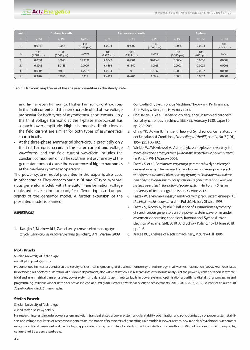
3. Calculation examplesSimulation calculations were carried out for long-lasting short-circuits, 1-phase to earth (in phase A), 2-phase clear of earth (in phases A and B) and 3-phase, at the distance l = 1% from the generating unit. In the calculations, breaks in the non short-circuited phases were additionally assumed. At the short-circuits to earth, the generator was operated with the grounded neutral point (closed switch WG in Fig. 3a, voltage vd = 0). The following load was assumed in the steady state before the short-circuit: active power P0 = 0.1 p.u. and reactive power Q0 = 0.05 p.u. The 1-phase short-circuit was analysed to determine the zero axial components of stator currents and voltages. Their effect on the phase waveforms was checked. In real high-voltage power systems, generators are usually operated with isolated neutral points.Figs. 4-6 show the waveforms of stator current ia and voltage vc, as well as generator field current Ifd (in relative units) for the analysed fault types.In Tab. 1, the harmonic amplitude distributions of the current in phase A, the voltage in phase C and the field current in the steady state are presented. The percentage values of higher harmonics are given in relation to the first harmonic for the stator quanti-ties, and in relation to the constant component for the generator field current. The reference values in relative units are given in brackets.
4. Final conclusionsThe following conclusions can be drawn from the performed investigations:
Fig. 3. Diagram of the PS at short-circuits: a) general, b) section modified to model a 1-phase short-circuit to earth, c) section modified to model a 3-phase short-circuit, d) for a 2-phase short-circuit clear of earth
P. Pruski, S. Paszek | Acta Energetica 1/38 (2019) | 17–22

21
• The maximum amplitude of the generator short-circuit current in the steady state occurs at the 1-phase short-circuit. The current amplitude at the 2-phase short-circuit in the steady state is higher than that at the 3-phase short-circuit. This is consistent with the synchronous machine theory [9].
• The waveforms of the analysed quantities in the considered types of short-circuits differ in amplitudes at the beginning of
the fault and in the steady state. The signal envelopes change in different ways.
• In the case of the asymmetrical short-circuits, odd harmonics with significant amplitudes occur in the waveforms of the short-circuit current and the voltage on the non short-circuited phase of the stator in the steady state. The generator field current in steady state includes the constant component
Fig. 4. Currents in phase A: a) envelopes, b) enlargement of one period in the steady state
Fig. 5. Voltages in phase A: a) envelopes, b) enlargement of one period in steady state
Fig. 6. Field currents: a) envelopes, b) enlargement of two periods in steady state
P. Pruski, S. Paszek | Acta Energetica 1/38 (2019) | 17–22
22
and higher even harmonics. Higher harmonics distributions in the fault current and the non short-circuited phase voltage are similar for both types of asymmetrical short-circuits. Only the third voltage harmonic at the 1-phase short-circuit has a much lower amplitude. Higher harmonics distributions in the field current are similar for both types of asymmetrical short-circuits.
• At the three-phase symmetrical short-circuit, practically only the first harmonic occurs in the stator current and voltage waveforms, and the field current waveform includes the constant component only. The subtransient asymmetry of the generator does not cause the occurrence of higher harmonics at the machine symmetric operation.
The power system model presented in the paper is also used in other studies. They concern various RL and XT-type synchro-nous generator models with the stator transformation voltage neglected or taken into account, for different input and output signals of the generator model. A further extension of the presented model is planned.
REFERENCES
1. Kacejko P., Machowski J., Zwarcia w systemach elektroenergetyc-znych [Short-circuits in power systems] (in Polish), WNT, Warsaw 2009.
Concordia Ch., Synchronous Machines. Theory and Performance, John Wiley & Sons, Inc., New York 1951.
2. Chassande J.P. et al., Transient low frequency unsymmetrical opera-tion of synchronous machines, IEEE-PES, February 1980, paper 80, pp. 208–209.
3. Ching Y.K., Adkins B., Transient Theory of Synchronous Generators un-der Unbalanced Conditions, Proceedings of the IEE, part IV, No. 7 (101), 1954, pp. 166-182.
4. Winkler W., Wiszniewski A., Automatyka zabezpieczeniowa w syste-mach elektroenergetycznych [Automatic protection in power systems] (in Polish), WNT, Warsaw 2004.
5. Paszek S. et al., Pomiarowa estymacja paramentów dynamicznych generatorów synchronicznych i układów wzbudzenia pracujących w krajowym systemie elektroenergetycznym [Measurement estima-tion of dynamic parameters of synchronous generators and excitation systems operated in the national power system] (in Polish), Silesian University of Technology Publishers, Gliwice 2013.
6. Paszek W., Dynamika maszyn elektrycznych prądu przemiennego [AC electrical machines dynamics] (in Polish), Helion, Gliwice 1998.
7. Paszek S., Nocoń A., Pruski P., Influence of subtransient asymmetry of synchronous generators on the power system waveforms under asymmetric operating conditions, International Symposium on Electrical Machines SME 2018, Andrychów, Poland, 10–13 June 2018, pp. 1–6.
8. Krause P.C., Analysis of electric machinery, McGraw-Hill, 1986.
Tab. 1. Harmonic amplitudes of the analysed quantities in the steady state
fault 1-phase to earth 2-phase clear of earth 3-phase
h iA [%] vC [%] Ifd [%] iA [%] vC [%] Ifd [%] iA [%] vC [%] Ifd [%]
0 0.0040 0.0006 100(1.269 p.u.) 0.0034 0.0002 100
(1.269 p.u.) 0.0006 0.0003 100(1.242 p.u.)
1. 100(1.085 p.u.)
100(0.242 p.u.) 0.0076 100
(0.627 p.u.)100
(0.218 p.u.) 0.0076 100(0.390 p.u.)
100(0.001 p.u.) 0.001
2. 0.0031 0.0023 27.9339 0.0042 0.0001 28.0348 0.0004 0.0006 0.0005
3. 6.3243 3.0133 0.0009 6.4894 6.4842 0.0023 0.0002 0.0003 0.0003
4. 0.0004 0.001 1.7587 0.0013 0 1.8107 0.0001 0.0002 0.0003
5. 0.3987 0.3976 0.001 0.4199 0.4206 0.0014 0.0001 0.0002 0.0002
Piotr PruskiSilesian University of Technology
e-mail: [email protected]
He completed his Master’s studies at the Faculty of Electrical Engineering of the Silesian University of Technology in Gliwice with distinction (2009). Four years later,
he defended his doctoral dissertation at his home department, also with distinction. His research interests include analysis of the power system operation in symme-
trical and asymmetrical transient states, power system angular stability, asymmetrical faults in power systems, optimisation algorithms, digital signal processing and
programming. Multiple winner of the collective 1st, 2nd and 3rd grade Rector’s awards for scientific achievements (2011, 2014, 2016, 2017). Author or co-author of
73 publications, incl. 2 monographs.
Stefan PaszekSilesian University of Technology
e-mail: [email protected]
His research interests include: power system analysis in transient states, a power system angular stability, optimisation and polyoptimisation of power system stabili-
sers and voltage regulators of synchronous generators, estimation of parameters of generating unit models in power system, new models of synchronous generators
using the artificial neural network technology, application of fuzzy controllers for electric machines. Author or co-author of 208 publications, incl. 6 monographs,
co-author of 3 academic textbooks.
P. Pruski, S. Paszek | Acta Energetica 1/38 (2019) | 17–22

2323
PL
Analiza przebiegów w systemie elektroenergetycznym przy zwarciach niesymetrycznych i symetrycznych w linii przesyłowej
Autorzy Piotr PruskiStefan Paszek
Słowa kluczowesystem elektroenergetyczny, asymetria obciążenia, zwarcie niesymetryczne, asymetria podprzejściowa generatora
StreszczenieW artykule analizowano przebiegi prądów i napięć generatora synchronicznego pracującego w jednomaszynowym systemie elek-troenergetycznym (SEE), składającym się z zespołu wytwórczego połączonego linią energetyczną wysokiego napięcia z siecią sztywną. Uwzględniono zakłócenia w postaci zwarć 1-fazowych, 2-fazowych bez udziału ziemi i 3-fazowych, występujących w linii przesyłowej. Prześledzono m.in. zawartość wyższych harmonicznych analizowanych wielkości w stanie ustalonym, w zależności od rodzaju zwarcia. W modelu generatora synchronicznego uwzględniono asymetrię podprzejściową, co podczas zwarć niesyme-trycznych powoduje wystąpienie wyższych harmonicznych w przebiegach m.in. prądu i napięcia twornika oraz prądu wzbudzenia. Te harmoniczne występują nawet przy braku uwzględniania zjawiska nasycenia rdzeni magnetycznych maszyny.
Data wpływu do redakcji: 11.02.2019Data wystawienia recenzji: 25.04.2019Data akceptacji artykułu: 29.04.2019Data publikacji online: 30.08.2019
1. WstępDużą część awarii występujących w systemie elektroenergetycznym stanowią zwarcia. Zazwyczaj są to zwarcia niesymetryczne, a tylko kilka procent z ogólnej liczby zwarć stanowią zwarcia symetryczne [1]. Niesymetryczny stan pracy SEE jest zwią-zany z niesymetrycznym stanem obciążenia generatorów synchronicznych. Wywołuje on wiele niekorzystnych zjawisk, m.in. dodat-kowe nagrzewanie się powierzchni wirnika i drgania mechaniczne elementów maszyn. Dlatego konieczne jest ograniczenie czasu trwania stanów niesymetrycznych [2].Ponieważ modelowanie niesymetrycz-nych stanów pracy SEE jest trudne, w badaniach symulacyjnych analizuje się przede wszystkim zwarcia symetryczne. Specjalistyczne oprogramowanie do analizy stanów nieustalonych SEE często umożliwia symulację jedynie symetrycznych stanów pracy. Oprogramowanie to nie pozwala zwykle na wprowadzanie zmian w gotowych modelach elementów SEE, nie umożliwia dostępu do wszystkich sygnałów wewnętrz-nych modelu ani wyboru metody całkowania równań stanu modelu. Przede wszystkim korzystanie z dużych, komercyjnych programów nie pozwala na pełną i dogłębną analizę pracy układu. Z tego powodu celowe jest prowadzenie badań symulacyjnych dotyczących analizy różnych niesymetrycz-nych stanów pracy SEE [2, 3, 4]. W bada-niach można zastosować powszechnie znane modele elementów zespołu wytwórczego, wprowadzając w nich pewne modyfikacje.Analiza niesymetrycznych stanów pracy SEE, w tym zwarć, może umożliwić m.in. lepszy dobór nastaw zabezpieczeń elek-troenergetycznych [5]. Przebiegi różnych wielkości występujących w SEE różnią się znacząco w zależności od rodzaju
występującej niesymetrii. Skutecznie działa-jąca automatyka zabezpieczeniowa pomaga zmniejszyć negatywne skutki zakłóceń, a tym samym rozmiar i skutki awarii wystę-pujących w SEE.Celem artykułu jest porównanie i analiza harmoniczna przebiegów zakłóceniowych wybranych wielkości w stanach ustalonych długotrwałych zwarć: 1-fazowego z ziemią, 2-fazowego bez udziału ziemi oraz 3-fazo-wego w jednomaszynowym SEE, składa-jącym się z zespołu wytwórczego (z gene-ratorem synchronicznym), linii przesyłowej wysokiego napięcia oraz sieci sztywnej. Wykorzystano model generatora synchro-nicznego GENROU (typu XT), w którym uwzględniono zjawiska asymetrii podprzej-ściowej generatora oraz nasycenia jego rdzeni magnetycznych. W przypadku zwarć doziemnych przyjęto, że generator pracuje z uziemionym punktem neutralnym, dlatego w przebiegach odpowiednich wielkości może występować składowa osiowa zerowa.
2. Model analizowanego SEEModel matematyczny SEE opracowano w środowisku programu Matlab Simulink. Model ten składa się z wyodrębnionego modelu zespołu wytwórczego, który jest połączony linią przesyłową wysokiego napięcia z siecią sztywną. Do symulacji wykorzystano zmodyfikowany program PARZW [6].
2.1. Model zespołu wytwórczegoW skład modelu zespołu wchodzi m.in. model generatora synchronicznego okre-ślony w układzie współrzędnych osiowych (d, q, 0) [6, 7].Wykorzystano model generatora GENROU [6] z uwzględnieniem asymetrii podprzej-ściowej (gdy: ) oraz zjawiska
nasycenia rdzeni magnetycznych maszyny. Jest to typowy model generatora synchro-nicznego typu XT, często stosowany w anali-zach pracy SEE [6]. Występują w nim po dwa zastępcze obwody wirnika w osiach d i q (obwód wzbudzenia i jeden zastępczy obwód tłumiący w osi d oraz dwa zastępcze obwody tłumiące w osi q). Napięcie trans-formacji stojana jest pomijane jako małe w porównaniu z napięciem rotacji gene-ratora. Na rys. 1 przedstawiono schematy blokowe modelu GENROU. Ich uzupeł-nieniem są równania różniczkowe ruchu wirnika maszyny [6]:
(1a)
(1b)
(1c)
Na rys. 1 i w równaniach (1) wprowadzono następujące oznaczenia: Ud, Uq, Id, Iq, Ψd, Ψq – napięcia, prądy i strumienie skoja-rzone stojana w osiach d i q; – fazor podprzejściowego strumienia skojarzonego; ΨD1, ΨQ1, IQ1 – strumienie skojarzone i prąd w pierwszym obwodzie tłumiącym w osiach d i q; – napięcia za reaktancją przejściową; Efd, Ifd – napięcie i prąd wzbudzenia; Ra, Xσ – rezystancja i reaktancja rozproszenia stojana; Xd, Xq, Xad, Xaq, – reaktancje: synchroniczne, magnesujące, przejściowe i podprzejściowe; – stałe czasowe przejściowe i podprzejściowe przy otwartym uzwojeniu stojana; Tm, D, Pm, Me, ∆ω, ωN, δ – mechaniczna stała czasowa, współczynnik tłumienia, moc mechaniczna
P. Pruski, S. Paszek | Acta Energetica 1/38 (2019) | translation 17–22

2424
PL
turbiny, moment elektromagnetyczny, odchyłka prędkości kątowej, znamio-nowa prędkość kątowa, kąt mocy. Składnik ∆(XadIfd) odpowiada za efekt nasycenia obwodu magnetycznego maszyny [6].W niektórych niesymetrycznych stanach pracy uzupełnieniem klasycznego modelu GENROU jest równanie dla składowej osiowej zerowej:
(2)
gdzie: U0, I0 – składowe zerowe napięcia i prądu stojana generatora, Ra – rezystancja uzwojenia stojana generatora, L0 – indukcyj-ność uzwojenia stojana generatora dla skła-dowej zerowej.
Sygnałami wejściowymi opracowanego modelu generatora są: napięcie wzbu-dzenia, moc mechaniczna turbiny oraz skła-dowe osiowe prądu stojana (Id, Iq oraz I0). Sygnałami wyjściowymi modelu generatora są m.in. składowe osiowe napięcia stojana (Ud, Uq oraz U0), napięcie zaciskowe stojana (U), moc chwilowa (P) i odchyłka prędkości kątowej generatora.
2.2. Równania wiążące wielkości stojana generatora, linii przesyłowej i sieci sztywnejAnalizując niesymetryczne stany SEE, równania prądów i napięć stojana generatora, linii przesyłowej i sieci sztywnej wygodnie jest zapisać z wykorzystaniem wielkości fazowych (A, B, C). Do powiązania równań fazowych z równaniami w układzie współrzędnym osiowym stosuje się transformację Parka:
(3a)
gdzie:
(3b)
(3c)
przy czym kąt określa przesunięcie pomiędzy osią fazy A uzwojenia 3-fazowego a osią d, zgodnie z rys. 2.Prędkość wirowania osiowego układu współ-rzędnych ωx może ogólnie zostać dowolnie przyjęta. Wówczas kąt w macierzy trans-formacji (3b) (przy założeniu zerowego kąta w chwili początku obserwacji t = 0) wynosi:
(4)
W dalszej części artykułu założono, że ωx równa jest wartości prędkości synchro-nicznej generatora.W badaniach uwzględniono różne niesyme-trie występujące w linii przesyłowej i opra-cowano stosowne modele linii elektroener-getycznej i sieci sztywnej.Na rys. 3 przedstawiono schemat analizo-wanego SEE podczas zwarć. Oznaczenia: ij – prądy stojana generatora, uj – napięcia stojana generatora, uSj – napięcia sieci sztywnej, Zj – zespolone impedancje linii przesyłowej (wielkości fazowe, j = A, B, C), Ifd – prąd wzbudzenia generatora, ur – napięcie między punktami neutralnymi generatora i sieci sztywnej (przy braku uzie-mienia punktu gwiazdowego generatora), t0 – chwila wystąpienia zakłócenia, WUZ – wyłącznik uziemienia punktu gwiazdowego generatora.
Rys. 1. Model generatora synchronicznego GENROU: a) – w osi d; b) – w osi q; c) – sposób uwzględnienia zjawiska nasycenia rdzeni magnetycznych [8]
Rys. 2. Położenie układów współrzędnych fazowego A, B, C i osiowego d, q (oś zerowa jest prostopadła do osi d i q) [8]
a)
b)
c)
P. Pruski, S. Paszek | Acta Energetica 1/38 (2019) | translation 17–22

2525
PL
Aby zamodelować zwarcie doziemne, należy w wybranych fazach przyjąć zerowe wartości napięcia sieci sztywnej uSj oraz proporcjo-nalnie zmniejszyć impedancje linii:
ZZj = l ∙ Zj, ZSj = Zj – ZZj (5)
gdzie: ZZj, ZSj – impedancje fragmentów linii dla j-tej fazy w czasie zwarcia, l – względna odległość miejsca zwarcia w linii przesy-łowej od zespołu wytwórczego, w odnie-sieniu do długości całej linii.W modelu linii przesyłowej – podobnie jak w równaniach stojana modelu GENROU generatora – pominięto napięcia transfor-macji. W związku z tym określono algebra-iczne związki pomiędzy prądami i napię-ciami. Dla faz zdrowych:
(6a)
dla faz ze zwarciem doziemnym:
(6b)
gdzie: ϕj – kąty fazowe odpowiednich impedancji linii przesyłowej, f = 50 Hz. Ze wzorów (6a) i (6b) uzyskuje się 3 równania. Dodatkowo dla układu z nieuziemionym punktem neutralnym generatora (otwarty wyłącznik WUZ z rys. 3a):
(6c)
Napięcia fazowe sieci sztywnej wyzna-czono z wykorzystaniem zależności (3) oraz równań na składowe d, q napięcia sieci (skła-dowa zerowa nie występuje w symetrycznym stanie ustalonym przed zakłóceniem):
(7a)
(7b)
(7c)
gdzie: US, US,d, US,q, – wartość skuteczna oraz składowe osiowe napięcia sieci sztywnej, δ – kąt mocy generatora, U, Ud, Uq, I, Id, Iq, – fazory oraz skła-dowe osiowe wartości ustalonych napięć i prądów generatora przed zakłóceniem, ZS, RS, XS – wartości zastępcze: impedancji zespolonej, rezystancji i reaktancji linii przesyłowej.Na podstawie napięć osiowych stojana generatora (sygnały wyjściowe modelu zespołu wytwórczego) oraz napięć osio-wych sieci sztywnej można wyznaczyć wiel-kości fazowe tych sygnałów przez odwrotną transformację Parka. Z układu równań (6) można więc obliczyć 3 lub 4 niewiadome: 3 prądy fazowe i ewentualnie napięcie ur. Jest to realizowane w opracowanym modelu SEE. Na podstawie prądów fazowych gene-ratora, korzystając z prostej transformacji Parka, obliczane są prądy osiowe generatora, stanowiące sygnały wejściowe modelu gene-ratora i modelu zespołu wytwórczego.Z kolei na rys. 3d przedstawiono schemat przedstawiający zwarcie 2-fazowe bez udziału ziemi w linii przesyłowej. Równania wiążące odpowiednie wielkości prądów i napięć dla tego zwarcia są następujące:
(8a)
(8b)
(8c)
(8d)
(8e)
gdzie: iSj – prądy sieci sztywnej; uzw – napięcie w miejscu zwarcia; Δtj, ΔtSj – opóźnienia czasowe przebiegów prądów, zdefiniowane jak w (6a); pozostałe oznaczenia jak we wzorach (6).Z układu równań (8) można obliczyć 7 wiel-kości: 5 prądów fazowych oraz napięcia uzw i ur. Tak określony model SEE jest pełny i umożliwia przeprowadzanie obliczeń symulacyjnych.
3. Przykładowe obliczeniaObliczenia symulacyjne przeprowadzono dla długotrwałych zwarć w odległości l = 1% od zespołu wytwórczego: 1-fazowego z ziemią (w fazie A), 2-fazowego bez udziału ziemi (w fazach A i B) oraz 3-fazowego. W obli-czeniach założono, że w niezwartych fazach występuje dodatkowo przerwa. Podczas zwarć doziemnych generator pracował z uziemionym punktem neutralnym (zwarty wyłącznik WUZ z rys. 3a, napięcie ur = 0). Przyjęto następujące obciążenie w stanie ustalonym przed zwarciem: mocą czynną P0 = 0,1 p.u. oraz mocą bierną Q0 = 0,05 p.u. Zwarcie 1-fazowe przeanalizowano w celu określenia składowych osiowych, zerowych prądów i napięć stojana, a także sprawdzono ich wpływ na przebiegi fazowe. W rzeczywi-stych wysokonapięciowych systemach elek-troenergetycznych generator pracuje zazwy-czaj z izolowanym punktem neutralnym.Na rys. 4–6 przedstawiono przebiegi prądu ia, napięcia uc stojana generatora oraz prądu wzbudzenia generatora Ifd (w jednost-kach względnych) dla analizowanych rodzajów zwarć.
Rys. 3. Schemat SEE podczas zwarć: a) – ogólny, b) – fragment zmodyfikowany w celu zamodelowania zwarcia 1-fazowego z udziałem ziemi, c) – fragment zmodyfikowany w celu zamodelowania zwarcia 3-fazowego, d) – podczas zwarcia 2-fazowego bez udziału ziemi
a)
c) d)
b)
P. Pruski, S. Paszek | Acta Energetica 1/38 (2019) | translation 17–22

2626
PL
Rys. 4. Przebiegi prądu w fazie A: a) – obwiednie, b) – powiększenie jednego okresu w stanie ustalonym
Rys. 5. Przebiegi napięcia w fazie C: a) – obwiednie, b) – powiększenie jednego okresu w stanie ustalonym
Rys. 6. Przebiegi prądu wzbudzenia: a) – obwiednie, b) – powiększenie dwóch okresów w stanie ustalonym
Tab. 1. Amplitudy harmonicznych analizowanych wielkości w stanie ustalonym
zwarcie 1f z ziemią 2f bez udziału ziemi 3f
h iA [%] uC [%] Ifd [%] iA [%] uC [%] Ifd [%] iA [%] uC [%] Ifd [%]
0 0,0040 0,0006 100(1,269 p.u.) 0,0034 0,0002 100
(1,269 p.u.) 0,0006 0,0003 100(1,242 p.u.)
1 100(1,085 p.u.)
100(0,242 p.u.) 0,0076 100
(0,627 p.u.)100
(0,218 p.u.) 0,0076 100(0,390 p.u.)
100(0,001 p.u.) 0,001
2 0,0031 0,0023 27,9339 0,0042 0,0001 28,0348 0,0004 0,0006 0,0005
3 6,3243 3,0133 0,0009 6,4894 6,4842 0,0023 0,0002 0,0003 0,0003
4 0,0004 0,001 1,7587 0,0013 0 1,8107 0,0001 0,0002 0,0003
5 0,3987 0,3976 0,001 0,4199 0,4206 0,0014 0,0001 0,0002 0,0002
a) b)
b)
b)
a)
a)
P. Pruski, S. Paszek | Acta Energetica 1/38 (2019) | translation 17–22

2727
PL
W tab. 1 przedstawiono rozkłady amplitud harmonicznych: prądu w fazie A, napięcia w fazie C i prądu wzbudzenia w stanie ustalonym. Podano procentowe wartości wyższych harmonicznych w odniesieniu do pierwszej harmonicznej dla wielkości stojana i w odniesieniu do składowej stałej dla prądu wzbudzenia generatora. W nawiasach podano wielkości odniesienia w jednostkach względnych.
4. Wnioski końcowePrzeprowadzone badania pozwoliły stwier-dzić, że:• Największa amplituda prądu zwarciowego
generatora w stanie ustalonym występuje przy zwarciu 1-fazowym. Z kolei ampli-tuda prądu przy zwarciu 2-fazowym w stanie ustalonym jest większa niż przy zwarciu 3-fazowym. Jest to zgodne z teorią maszyn synchronicznych [9].
• Przebiegi analizowanych wielkości w rozpatrywanych typach zwarć różnią się amplitudami na początku zwarcia i w stanie ustalonym. W różny sposób zmieniają się obwiednie sygnałów.
• Podczas zwarć niesymetrycznych, w przebiegach prądu zwarcia i napięcia na niezwartej fazie stojana w stanie ustalonym występują harmoniczne nieparzyste o znaczących amplitu-dach. W prądzie wzbudzenia generatora w stanie ustalonym występują: składowa stała i wyższe harmoniczne parzyste. Rozkład wyższych harmonicznych w prądzie zwarcia i napięciu niezwartej fazy jest podobny dla obu typów zwarć niesymetrycznych. Jedynie trzecia
harmoniczna napięcia przy zwarciu 1-fazowym ma znacznie mniejszą ampli-tudę. Rozkład wyższych harmonicznych w prądzie wzbudzenia jest podobny dla obu typów zwarć niesymetrycznych.
• Podczas zwarcia symetrycznego 3-fazo-wego, w przebiegach prądu i napięcia stojana występuje praktycznie tylko pierwsza harmoniczna, a w przebiegu prądu wzbudzenia tylko składowa stała. Asymetria podprzejściowa generatora nie powoduje wystąpienia wyższych harmonicznych przy symetrycznej pracy maszyny.
Przedstawiony w artykule model SEE jest także wykorzystywany w innych badaniach. Brane są w nich pod uwagę m.in. różne modele generatora synchronicznego typu RL i XT, z pominięciem i uwzględnieniem napięcia transformacji w stojanie, przy różnych sygnałach wejściowych i wyjścio-wych modelu generatora. Planowana jest dalsza rozbudowa przedstawionego modelu.
Bibliografia
1. Kacejko P., Machowski J., Zwarcia w syste-mach elektroenergetycznych, WNT, Warszawa 2009.
2. Concordia Ch., Synchronous Machines. Theory and Performance, John Wiley & Sons, Inc., New York 1951.
3. Chassande J.P. i in., Transient low frequency unsymmetrical operation of synchronous machines, IEEE-PES, February 1980, paper 80, s. 208–209.
4. Ching Y.K., Adkins B., Transient Theory of Synchronous Generators under Unbalanced Conditions, Proceedings of the IEE 1954, part IV, No. 7 (101), s. 166–182.
5. Winkler W., Wiszniewski A., Automatyka zabezpieczeniowa w systemach elektro-energetycznych, WNT, Warszawa 2004.
6. Paszek S. i in., Pomiarowa estymacja parametrów dynamicznych generatorów synchronicznych i układów wzbudzenia pracujących w Krajowym Systemie Elektroenergetycznym, Wydawnictwo Politechniki Śląskiej, Gliwice 2013.
7. Paszek W., Dynamika maszyn elektrycz-nych prądu przemiennego, Wydawnictwo Helion, Gliwice 1998.
8. Paszek S., Nocoń A., Pruski P., Influence of subtransient asymmetry of synchro-nous generators on the power system waveforms under asymmetric operating conditions, International Symposium on Electrical Machines SME 2018, Andrychów, Poland, 10–13 June 2018, s. 1–6.
9. Krause P.C., Analysis of electric machi-nery, McGraw-Hill, 1986.
Piotr Pruskidr inż.Politechnika Śląskae-mail: [email protected] magisterskie na Wydziale Elektrycznym Politechniki Śląskiej w Gliwicach ukończył z wyróżnieniem (2009). Cztery lata później obronił, także z wyróż-nieniem, rozprawę doktorską na swoim macierzystym wydziale. Jego zainteresowania badawcze to analiza pracy systemu elektroenergetycznego (SEE) w symetrycznych i niesymetrycznych stanach nieustalonych, stabilność kątowa SEE, zwarcia niesymetryczne w SEE, algorytmy optymalizacyjne, cyfrowe przetwarzanie sygnałów oraz programowanie. Wielokrotny laureat zespołowych nagród rektora stopnia I, II i III za osiągnięcia naukowe (2011, 2014, 2016, 2017). Autor i współautor 73 publikacji, w tym 2 monografii.
Stefan Paszekprof. dr hab. inż.Politechnika Śląskae-mail: [email protected] obszarze jego zainteresowań naukowych są: analiza systemu elektroenergetycznego (SEE) w stanach nieustalonych, stabilność kątowa SEE, optymalizacja i polioptymalizacja stabilizatorów systemowych oraz regulatorów napięcia generatorów synchronicznych, estymacja parametrów modeli zespołów wytwór-czych SEE, nowe modele generatorów synchronicznych przy zastosowaniu techniki sztucznej sieci neuronowej, zastosowanie regulatorów rozmytych w ukła-dach regulacji maszyn elektrycznych. Autor i współautor 208 publikacji, w tym 6 monografii, współautor 3 podręczników akademickich.
P. Pruski, S. Paszek | Acta Energetica 1/38 (2019) | translation 17–22