analog and digital combined: mixed-signal design and ...€¦ · mixed-signal design and...
TRANSCRIPT

1 © 2013 The MathWorks, Inc.
Analog and Digital combined:
Mixed-Signal Design and Verification in
MATLAB and Simulink
Alexander Schreiber – Senior Application Engineer
MathWorks, Germany

2
Agenda
Analog/Mixed-Signal Design Challenges
Case Studies
– Analog-Digital-Converter
Modelling on different levels of abstraction
Architectural Exploration
– Digital Pre-Distortion
Device characterisation (transistor-level simulation, measurement)
Device modelling
Compensation algorithm development
Verification
Summary

3
DESIGN
PROTOTYPE
TE
ST
& V
ER
IFIC
AT
ION
Analog
SPICE
DESIGN
Digital
VHDL,
Verilog
Digital
Hardware
Analog
Hardware
Specification
isolated from
verification
No run-time
analog/digital
links
Disconnected
teams
Design trade-
offs difficult
Limited
analog design
abstractions
SPECIFICATION
Slow design
iterations
Classical Mixed-Signal Design

4
Model-Based Mixed-Signal Design
Design & simulation
speed
– rapid construction
– design abstractions
Design links
– multiple domains (analog,
digital, network, …)
– multiple tools (ModelSim,
Spectre…)
– specification and verification
– system-level and test
equipment
PROTOTYPE
SYSTEM-DESIGN
SPECIFICATION
TE
ST
& V
ER
IFIC
AT
ION
Analog
SPICE
Digital
VHDL,
Verilog
Digital
Hardware
Analog
Hardware
System
Simulink
5
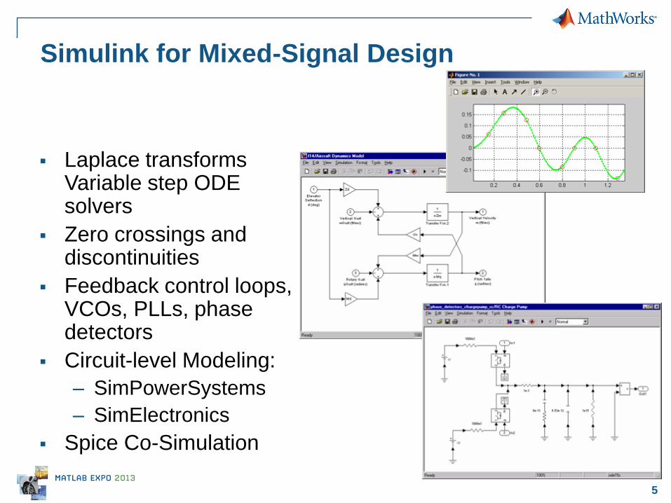
Laplace transforms Variable step ODE solvers
Zero crossings and discontinuities
Feedback control loops, VCOs, PLLs, phase detectors
Circuit-level Modeling:
– SimPowerSystems
– SimElectronics
Spice Co-Simulation
Simulink for Mixed-Signal Design

6 © 2013 The MathWorks, Inc.
Case Study:
ADC Design

7
Agenda
Case study What we’ll show
Analog-Digital
Converter
Introduction to methods – sigma-delta ADC
Design abstractions
Analog/digital in same model
8
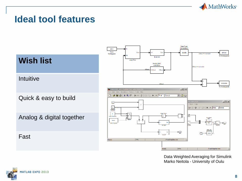
Ideal tool features
Wish list
Intuitive
Quick & easy to build
Analog & digital together
Fast
Data Weighted Averaging for Simulink
Marko Neitola - University of Oulu

9
Case study: ADC design
Purpose:
Introduce methods using straight forward design
Design Challenge:
Sigma-delta ADC to process AM signals around 1,600
kHz
10
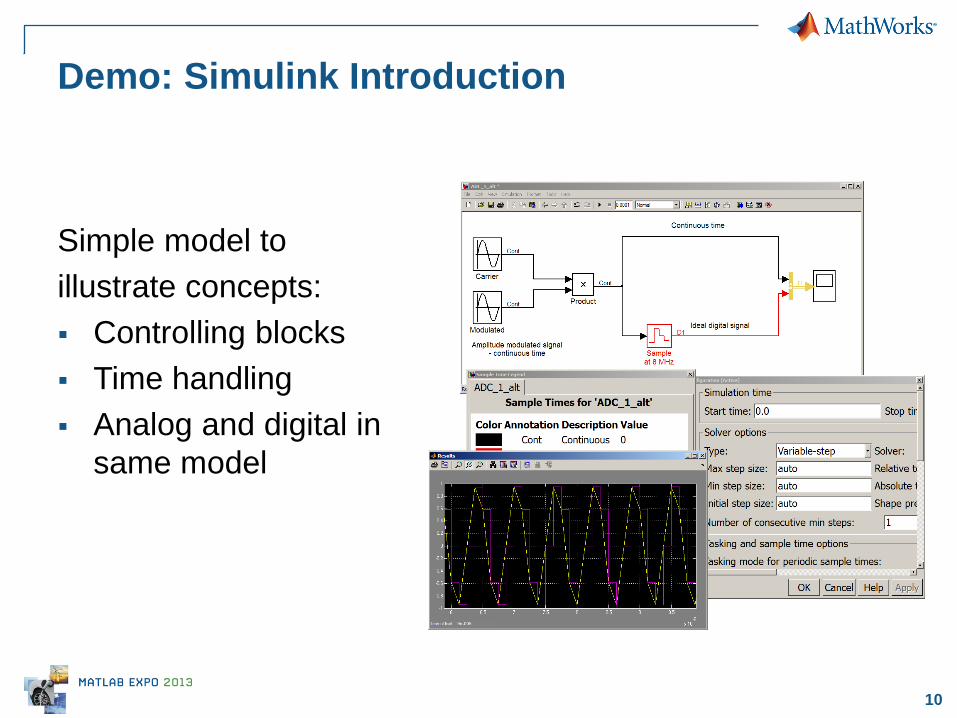
Demo: Simulink Introduction
Simple model to
illustrate concepts:
Controlling blocks
Time handling
Analog and digital in
same model
11
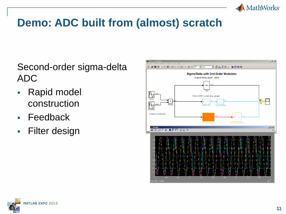
Demo: ADC built from (almost) scratch
Second-order sigma-delta
ADC
Rapid model
construction
Feedback
Filter design

12
Demo: Circuit elements
Switched capacitor
ADC
Circuit elements
Mixed-behavioral
and circuit
design

13
More complex ADCs & DACs possible
Improved Modeling of Sigma-Delta Modulator Non-Idealities in SIMULINK, A. Fornasari, P.
Malcovati and F. Maloberti, ISCAS 2005
Modeling of Switched-Capacitor Delta–Sigma Modulators in SIMULINK, Hashem Zare-Hoseini, Izzet Kale, and Omid Shoaei,
IEEE TRANSACTIONS ON INSTRUMENTATION AND MEASUREMENT, 2005

14 © 2013 The MathWorks, Inc.
Case Study:
Digital Pre-Distortion
15
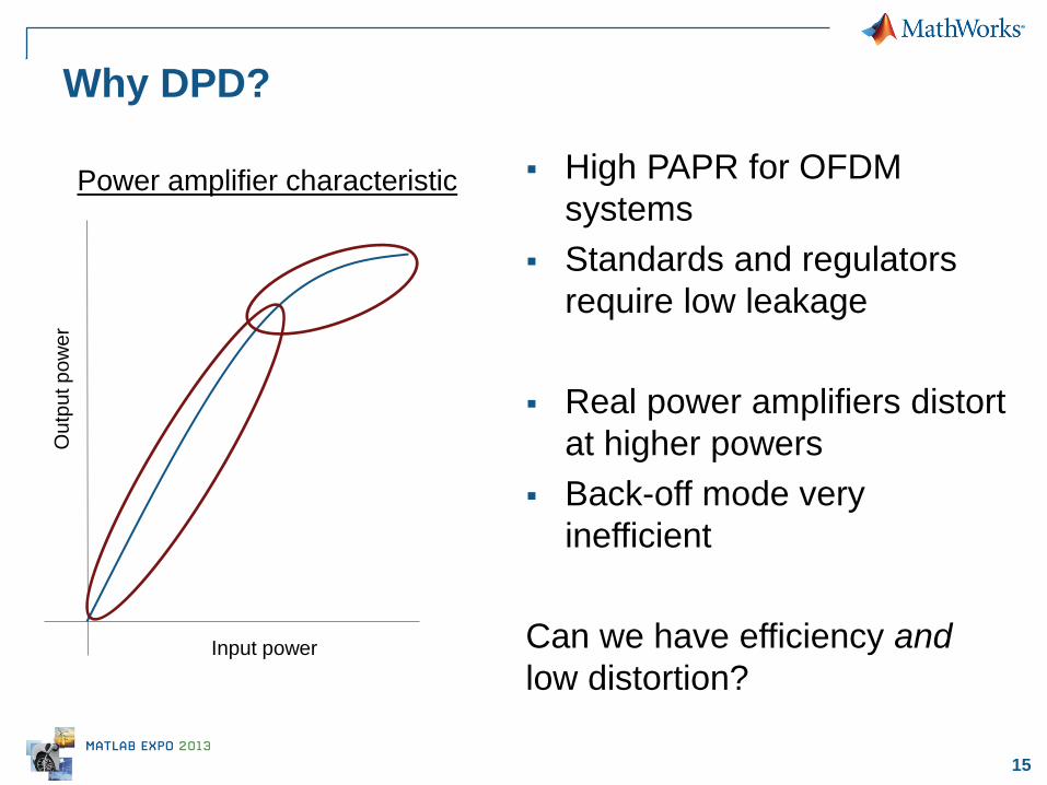
Why DPD?
High PAPR for OFDM
systems
Standards and regulators
require low leakage
Real power amplifiers distort
at higher powers
Back-off mode very
inefficient
Can we have efficiency and
low distortion? Input power
Ou
tpu
t p
ow
er
Power amplifier characteristic

16
What is Digital Pre-Distortion?
Power amplifier distorts
signal
Digitally pre-distort signal
Predisortion + power
amplifier = ideal result
Input power
Ou
tpu
t p
ow
er
Power amplifier characteristic
PA DPD
17
Ph
ys
ica
l
Ve
rifi
cati
on
Alg
ori
thm
De
ve
lop
me
nt
Ab
str
ac
t
De
vic
e M
od
elin
g
De
vic
e
Ch
ara
cte
riza
tio
n
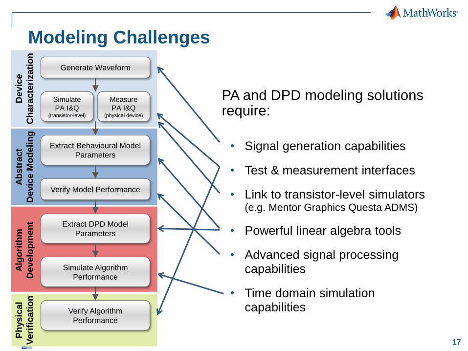
Modeling Challenges
PA and DPD modeling solutions require:
• Signal generation capabilities
• Test & measurement interfaces
• Link to transistor-level simulators (e.g. Mentor Graphics Questa ADMS)
• Powerful linear algebra tools
• Advanced signal processing capabilities
• Time domain simulation capabilities
Generate Waveform
Simulate
PA I&Q (transistor-level)
Extract Behavioural Model
Parameters
Verify Model Performance
Extract DPD Model
Parameters
Simulate Algorithm
Performance
Verify Algorithm
Performance
Measure
PA I&Q (physical device)

18
Ph
ys
ica
l
Ve
rifi
cati
on
Modeling Challenges
Alg
ori
thm
De
ve
lop
me
nt
Ab
str
ac
t
De
vic
e M
od
elin
g
De
vic
e
Ch
ara
cte
riza
tio
n
Generate Waveform
Extract Behavioural Model
Parameters
Verify Model Performance
Extract DPD Model
Parameters
Simulate Algorithm
Performance
Verify Algorithm
Performance
MATLAB, Simulink
MATLAB, Signal Processing Toolbox
MATLAB, Signal Processing Toolbox
Simulink, DSP System Toolbox
Instrument Control Toolbox
Simulate
PA I&Q (transistor-level)
Measure
PA I&Q (physical device)
Instrument Control Toolbox
HDL Verifier Mentor Graphics
Questa ADMS
19
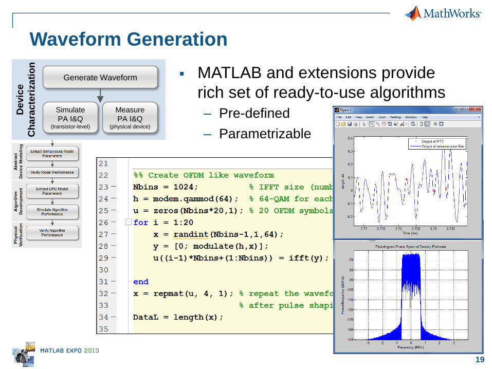
Waveform Generation
MATLAB and extensions provide
rich set of ready-to-use algorithms
– Pre-defined
– Parametrizable
De
vic
e
Ch
ara
cte
riza
tio
n
Generate Waveform
Simulate
PA I&Q (transistor-level)
Measure
PA I&Q (physical device)
20
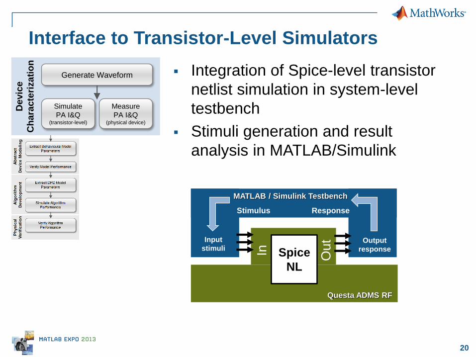
Interface to Transistor-Level Simulators
Integration of Spice-level transistor
netlist simulation in system-level
testbench
Stimuli generation and result
analysis in MATLAB/Simulink
De
vic
e
Ch
ara
cte
riza
tio
n
Generate Waveform
Simulate
PA I&Q (transistor-level)
Measure
PA I&Q (physical device)
Spice
NL In
Ou
t
Questa ADMS RF
MATLAB / Simulink Testbench
Stimulus Response
Input
stimuli Output
response

21
Example: Interface to Transistor-Level Simulators
De
vic
e
Ch
ara
cte
riza
tio
n
Generate Waveform
Simulate
PA I&Q (transistor-level)
Measure
PA I&Q (physical device)
ADMS
SPICE Verilog-AMS
Fast SPICE VHDL-AMS
Constraint
Solver Simulator
Functional
Coverage
Assertion
Engine
HD
L V
eri
fie
r

23
Interface to Transistor-Level Simulators
De
vic
e
Ch
ara
cte
riza
tio
n
Generate Waveform
Simulate
PA I&Q (transistor-level)
Measure
PA I&Q (physical device)

24
via 3rd party solution:
Cadence
– OrCAD SLPS
– Virtuoso AMS Designer Simulink
Integrator
Mentor Graphics Questa ADMS
Co-Simulation with Analog Simulators
25
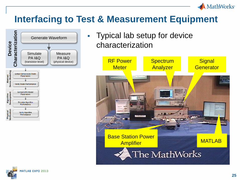
Interfacing to Test & Measurement Equipment
De
vic
e
Ch
ara
cte
riza
tio
n
Generate Waveform
RF Power
Meter
Spectrum
Analyzer
MATLAB Base Station Power
Amplifier
Signal
Generator
Typical lab setup for device
characterization Simulate
PA I&Q (transistor-level)
Measure
PA I&Q (physical device)
26
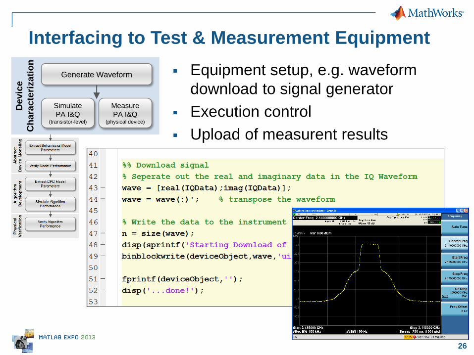
Interfacing to Test & Measurement Equipment
Equipment setup, e.g. waveform
download to signal generator
Execution control
Upload of measurent results
De
vic
e
Ch
ara
cte
riza
tio
n
Generate Waveform
Simulate
PA I&Q (transistor-level)
Measure
PA I&Q (physical device)
27
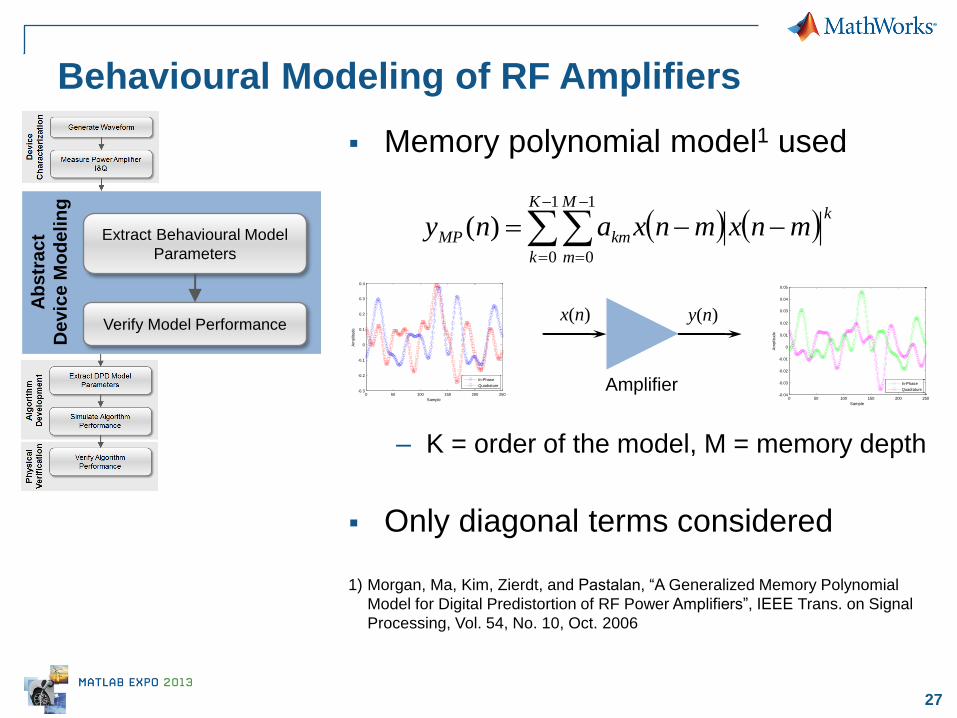
Behavioural Modeling of RF Amplifiers
Ab
str
ac
t
De
vic
e M
od
elin
g
Extract Behavioural Model
Parameters
Verify Model Performance
Memory polynomial model1 used
– K = order of the model, M = memory depth
Only diagonal terms considered
1) Morgan, Ma, Kim, Zierdt, and Pastalan, “A Generalized Memory Polynomial
Model for Digital Predistortion of RF Power Amplifiers”, IEEE Trans. on Signal
Processing, Vol. 54, No. 10, Oct. 2006
kK
k
M
m
kmMP mnxmnxany
1
0
1
0
)(
x(n) y(n)
Amplifier 0 50 100 150 200 250
-0.04
-0.03
-0.02
-0.01
0
0.01
0.02
0.03
0.04
0.05
Sample
Am
plit
ude
In-Phase
Quadrature
0 50 100 150 200 250-0.3
-0.2
-0.1
0
0.1
0.2
0.3
0.4
Sample
Am
plit
ude
In-Phase
Quadrature
28
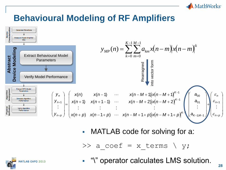
Behavioural Modeling of RF Amplifiers
Ab
str
ac
t
De
vic
e M
od
elin
g
Extract Behavioural Model
Parameters
Verify Model Performance
MATLAB code for solving for a:
>> a_coef = x_terms \ y;
“\” operator calculates LMS solution.
kK
k
M
m
kmMP mnxmnxany
1
0
1
0
)(
pn
n
n
MKK
K
K
pn
n
n
a
a
a
pMnxpMnxpnxpnx
MnxMnxnxnx
MnxMnxnxnx
y
y
y
1
1,1
01
00
1
1
1
1
1)1()1()(
2)2()11()1(
1)1()1()(
Rea
rra
gn
ed
into
ve
cto
r fo
rm
29
Behavioural Modeling of RF Amplifiers
Ab
str
ac
t
De
vic
e M
od
elin
g
Extract Behavioural Model
Parameters
Verify Model Performance
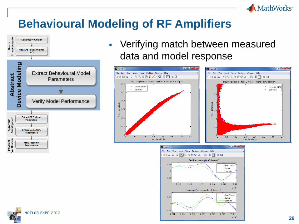
Verifying match between measured
data and model response
30
DPD Algorithm Development & Verification A
lgo
rith
m
De
ve
lop
me
nt Extract DPD Model
Parameters
Simulate Algorithm
Performance
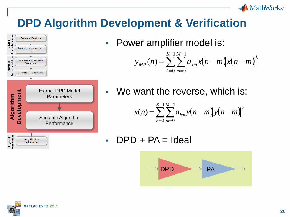
Power amplifier model is:
We want the reverse, which is:
DPD + PA = Ideal
kK
k
M
m
kmMP mnxmnxany
1
0
1
0
)(
kK
k
M
m
km mnymnyanx
1
0
1
0
)(
PA DPD

31
DPD Algorithm Development & Verification A
lgo
rith
m
De
ve
lop
me
nt Extract DPD Model
Parameters
Simulate Algorithm
Performance
Same MATLAB code as before:
Parameters fit by:
>> a_coef = x_terms \ y;
Model results given by:
>> y = x_terms * a;
32
DPD Algorithm Development & Verification A
lgo
rith
m
De
ve
lop
me
nt Extract DPD Model
Parameters
Simulate Algorithm
Performance
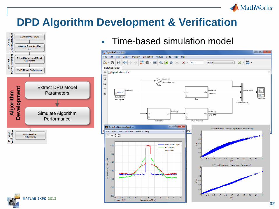
Time-based simulation model
33
Ph
ys
ica
l
Ve
rifi
cati
on
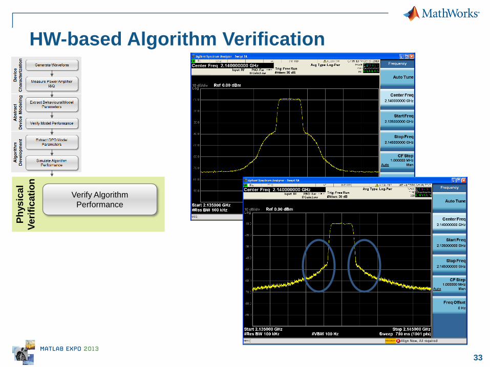
HW-based Algorithm Verification
Verify Algorithm
Performance

34 © 2013 The MathWorks, Inc.
Summary

35
Model-Based Mixed-Signal Design
Design & simulation
speed
– rapid construction
– design abstractions
Design links
– multiple domains (analog,
digital, …)
– multiple tools (ModelSim,
Spectre…)
– specification and verification
– system-level and test
equipment
PROTOTYPE
SYSTEM-DESIGN
SPECIFICATION
TE
ST
& V
ER
IFIC
AT
ION
Analog
SPICE
Digital
VHDL,
Verilog
Digital
Hardware
Analog
Hardware
System
Simulink
36
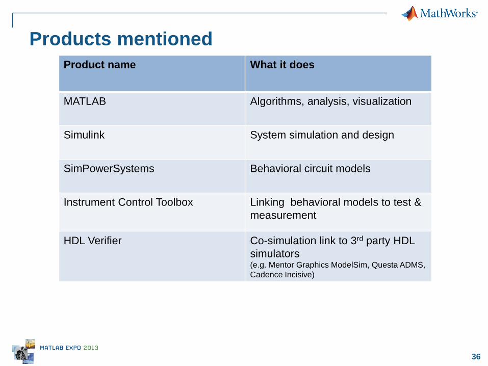
Products mentioned
Product name What it does
MATLAB Algorithms, analysis, visualization
Simulink System simulation and design
SimPowerSystems Behavioral circuit models
Instrument Control Toolbox Linking behavioral models to test &
measurement
HDL Verifier Co-simulation link to 3rd party HDL
simulators (e.g. Mentor Graphics ModelSim, Questa ADMS,
Cadence Incisive)
37
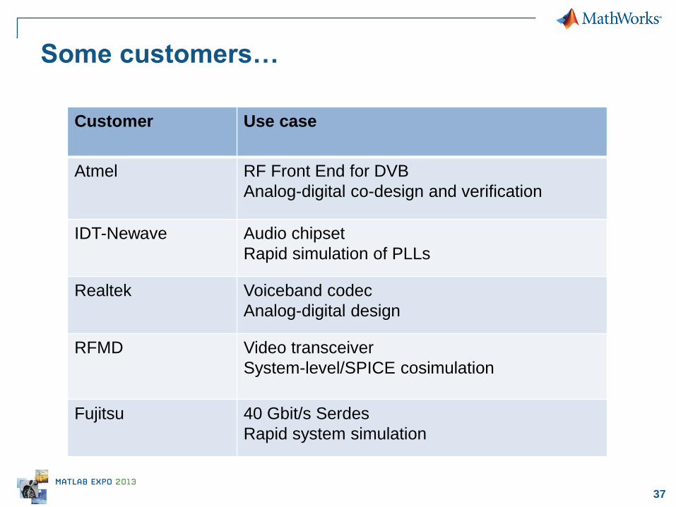
Some customers…
Customer Use case
Atmel RF Front End for DVB
Analog-digital co-design and verification
IDT-Newave Audio chipset
Rapid simulation of PLLs
Realtek Voiceband codec
Analog-digital design
RFMD Video transceiver
System-level/SPICE cosimulation
Fujitsu 40 Gbit/s Serdes
Rapid system simulation
38
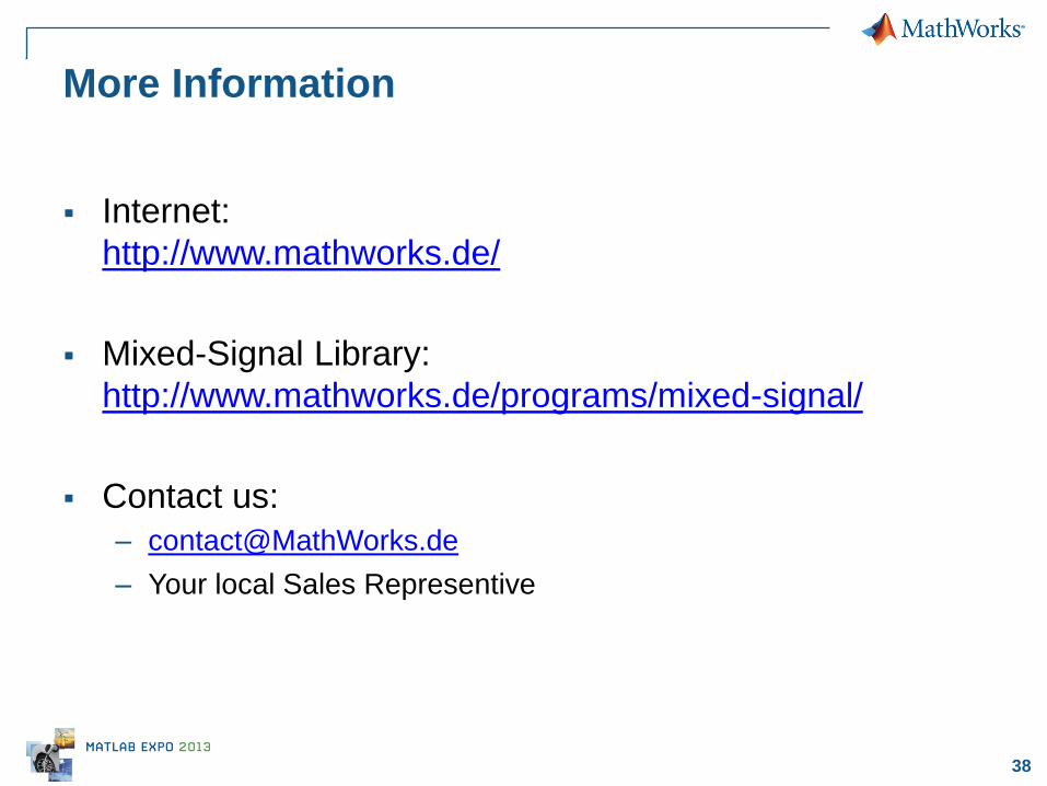
More Information
Internet:
http://www.mathworks.de/
Mixed-Signal Library:
http://www.mathworks.de/programs/mixed-signal/
Contact us:
– Your local Sales Representive

39 © 2013 The MathWorks, Inc.
Questions?

40 © 2013 The MathWorks, Inc.
Thank you!