anaerobic phased solids digester -...
TRANSCRIPT
Anaerobic Phased Solids Digester
Pilot Demonstration Project
CALIFORNIA
ENERGY
COMMISSION
Pilot Digester Construction Report
CO
NT
RA
CT
OR
RE
PO
RT
August 2008

Arnold Schwarzenegger, Governor
CALIFORNIA
ENERGY
COMMISSION
Prepared By:
Dave Konwinski, OPS Ruihong Zhang, UC Davis
Scott Archibald, OPS
Hamed El-Mashed, UC Davis Josh Rapport, UC Davis
Iain Clark, UC Davis
Prepared For:
Valentino Tiangco
Project Manager
Ron Kukulka
PIER Program Director
Robert L. Therkelsen
Executive Director

1
Legal Notice
This report was prepared as a result of work sponsored by the California Energy Commission
(Commission, Energy Commission). It does not necessarily represent the views of the
Commission, its employees, or the State of California. The Commission, the State of California,
its employees, contractors, and subcontractors make no warranty, express or implied, and assume
no legal liability for the information in this report; nor does any party represent that the use of
this information will not infringe upon privately owned rights. This report has not been approved
or disapproved by the Commission nor has the Commission passed upon the accuracy or
adequacy of this information in this report.
2
Anaerobic Phased Solids Digester
Pilot Demonstration Project
Construction Specifications and Process Operational Protocol
&
Material Handling, Mechanical & Process Components
Contact Information:
Dave Konwinski
Onsite Power Systems, Inc
Phone: (559) 271-2970 e-mail: [email protected]
Ruihong Zhang
Biological and Agricultural Engineering Department
University of California, Davis
Phone: (530)754-9530, email: [email protected]
3
Executive Summary
The University of California, Davis (UC Davis) received a research grant from the Public
Interest Energy Research (PIER) program of California Energy Commission to develop and
construct a pilot-scale anaerobic digester system based on the Anaerobic Phased Solids
Digester (APS-Digester) technology. The pilot digester system will be used to demonstrate
and test the APS-Digester technology at a larger scale than the bench-scales used in previous
laboratory studies, with regards to material handling, heat transfer, reactor level control and
stability, computer controls, biogas collection and utilization, and digestate collection and
utilization. The knowledge and research data gained from this pilot digester system will be
used to guide the design and construction of a commercial scale APS-Digester system.
The APS-Digester system combines favorable features of both batch and continuous
biological processes in a single biological system and makes it possible to achieve efficient
and stable production of both hydrogen and methane gases from a variety of organic solid
and liquid wastes, including grass clippings, food leftovers, food processing byproducts, crop
residues, and animal wastes. The pilot digester system is housed in the newly developed UC
Davis Biogas Energy Plant and has a capacity of treating 3 to 8 tons per day organic waste
with expected biogas production of producing 11,400-22,900 ft3
per day biogas. It has
employed innovative design features and state of the art equipment and control technologies
that provide optimum conditions for fast microbial degradation of organic wastes and
efficient material handling. At present, the biogas is used for electricity and heat generation.
Additional capability can be added to purify and compress the biogas for producing
compressed or liquefied fuels.
The research team for the development of the pilot digester system consists of members from
the University of California, Davis and Onsite Power Systems, Inc. The capital for design
and construction of the pilot digester system is provided by the research grants from
California Energy Commission and University of California, Davis and in-kind and cash
funds provided by Onsite Power Systems. The following companies have also made
contributions to the development and construction of the pilot digester system,
Brown and Caldwell (Computer controls design)
Rockwell Engineering (Material processing and hydraulic mixing)
Mazzie Injectors (Hydraulic mixing)
Kouba Engineering (Engineering design review)
GraybaR (Instrumentation and controls components)
Advanced Food Technologies (Material processing equipment and design)
Wonderware (Computer control and data collection programs)
4
Table of Contents
Acronyms / Abbreviations ........................................................................................................ 5 List of Figures ........................................................................................................................... 6 1. Introduction ....................................................................................................................... 7
2. Project Overview .............................................................................................................. 7 2.1. APS-Digester technology overview .......................................................................... 7
3. Pilot Digester Construction Specifications ....................................................................... 9 3.1. Concrete pad ............................................................................................................. 9 3.2. Reactor vessels .......................................................................................................... 9
3.3. Boilers and Heat exchangers ................................................................................... 11 3.3.1. Heat Exchangers ............................................................................................. 12
4. Material Handling and Digester Operational Equipment ............................................... 13 4.1. Hydrolysis reactor loading ...................................................................................... 13
4.2. Liquid circulation process ....................................................................................... 17 4.3. Internal hydraulic mixing system – HT 1 and HT 2 ............................................... 18
4.4. Hydraulic internal mixing system – HT 3 and HT 4 .............................................. 19 4.5. Hydraulic internal mixing system - GT .................................................................. 19
4.6. Solids residue and water recovery .......................................................................... 20 4.7. Tank pressure/vacuum equalization ........................................................................ 21 4.8. Safety pressure relief valve ..................................................................................... 21
4.9. Limiting introduction of air into the system ........................................................... 22 4.10. Computer control system ........................................................................................ 22
4.11. OPS proprietary computer controls software and process protocol ........................ 25 5. Biogas Collection and Processing System ...................................................................... 26
5.1. Biogas collection ..................................................................................................... 26
5.2. Biogas compression ................................................................................................ 28
5.3. Electrical generator ................................................................................................. 29 5.4. Safety biogas flare................................................................................................... 30
6. Safety and Environmental Considerations ...................................................................... 30
6.1. Safety considerations .............................................................................................. 30 6.2. Environmental considerations ................................................................................. 31
7. Equipment and Cost of UC Davis Biogas Energy Plant ................................................. 32 8. References ....................................................................................................................... 36
9. Acknowledgement .......................................................................................................... 36
5
Acronyms / Abbreviations
ADS = anaerobic digester system
APS = anaerobic phased solids
BTGT = buffer tank biogasification tank
BT = buffer tank
Btu = British thermal unit
CEC = California Energy Commission
CDS = commercial demonstration system o F = degree Fahrenheit
DV = decant valve
RWT = reclaimed water tank
RWV = reclaimed water valve
ft2 = square foot
ft3 = cubic foot
FSD = facilities services department
gals = gallons
GT = tank
H1 = hydrolysis tank 1
H2 = hydrolysis tank 2
H3 = hydrolysis tank 3
H4 = hydrolysis tank 4
HMV = hydraulic mixing valve
HT = hydrolysis tank
IIPP = injury illness prevention program
in = inches
IV = inlet valve
kW = kilowatt
kWh = kilowatt hour
lb = pounds
MIV = Mazzie injector valve
OPS = Onsite Power Systems, Inc.
PBM = pressure balanced manifold
PM = project manager
psi = pounds per square inch
reqd = required
RV = relief valve
SCADA = supervisory control and data acquisition
SS = stainless steel
TRV = top re-circulation valve
TS = total solids
UC = University of California
UCD-RT = University of California, Davis research team
VS = volatile solids
Xfer = transfer

6
List of Figures
Figure 1. A schematic of APS-Digester System ....................................................................... 8
Figure 2 . Main frontal view of digester system with loading dock ......................................... 9
Figure 3. Five anaerobic reactors including four hydrolysis reactors and one biogasification
reactor ............................................................................................................................. 10
Figure 4. Buffer tank located between hydrolysis and biogasification reactors ..................... 11
Figure 5. Dual boiler systems ................................................................................................. 11
Figure 6. Propane operated boiler for system start-up ............................................................ 12
Figure 7. GT external heat exchanger system ......................................................................... 12
Figure 8. Air fin heat exchanger system ................................................................................. 13
Figure 9. Delivery of bins containing feedstock materials ..................................................... 13
Figure 10. Bins of waste materials delivered for loading ....................................................... 14
Figure 11. Forklift dumps bin into receiving hopper .............................................................. 14
Figure 12. Receiving hopper metering feedstock into conveyor system ................................ 15
Figure 13. Conveyor delivers feedstock to hydraulic piston pumps ....................................... 15
Figure 14. Hydraulic piston pump located at HT 3 and HT 4 ................................................ 16
Figure 15. Hydraulic piston pump located at HT 1 and HT 2 ................................................ 16
Figure 16. Valve system for HT loading ................................................................................ 17
Figure 17 Screen filter, self cleaning system .......................................................................... 17
Figure 18. pH meter and circulation buffer tank ..................................................................... 18
Figure 19. In-line chopper pipe and pipe system .................................................................... 18
Figure 20 Hydraulic mixing pump HT 3 and HT 4 ................................................................ 19
Figure 21 GT hydraulic mixing pump and pipe system ......................................................... 19
Figure 22. HT drain valve and connection to drain system .................................................... 20
Figure 23. Drain section to be connected to pump and screw press unit ................................ 21
Figure 24. Pressure relieve units and flame arrester ............................................................... 22
Figure 25 Process flow monitoring screen.............................................................................. 23
Figure 26. Spread spectrum wireless data transmission boxes ............................................... 24
Figure 27. Biogas flow, Biohydrogen flow and pH meters .................................................... 24
Figure 28. Motor control cabinet with HMI interface panel ................................................... 25
Figure 29. One of three magnetic flow meters ....................................................................... 25
Figure 30. Biogas collection manifold .................................................................................... 26
Figure 31. Hydrogen sulfide filter with SulfaTreat ................................................................ 27
Figure 32: Coalescent filter, expansion tank and drain traps (located on ground) ................. 27
Figure 33 Biogas pressure regulator system ........................................................................... 28
Figure 34. Biogas blower unit ................................................................................................. 28
Figure 35. Engine-generator system with control switch box ................................................ 29
Figure 36. Engine-generator system with control switch box ................................................ 30
7
1. Introduction
The UC Davis Biogas Energy Project is funded by California Energy Commission to scale-
up, test, and demonstrate a new anaerobic digestion technology called the Anaerobic Phased
Solids Digester system (APS-Digester) (U.S. patent 6,342,378). The APS-Digester
technology was developed at the University of California, Davis and is an advanced
technology with innovative design features that optimize the microbial degradation of
organic wastes, provide efficient material handling solutions, and combine the favorable
features of both batch and continuous operations in a single biological system. The APS-
Digester system has been proven to be reliable and stable at the laboratory level for
converting various types of organic wastes to biogas. The pilot digester system is developed
to examine the material handling, actual waste stream characteristics, digester performance,
residual material characteristics and value at a larger scale. The knowledge and research data
gained from the pilot digester system will be used to design and build a commercial APS-
Digester system. A pilot-scale APS-Digester has been constructed on the campus of UC
Davis according to the engineering design described in a previous report submitted to
California Energy Commission (Zhang et al., 2005). This report documents the equipment
and components, and construction process that have been built into the pilot digester system
at UC Davis Biogas Energy Plant.
2. Project Overview
2.1. APS-Digester technology overview
The APS-Digester developed at UC Davis is a multiple reactor, two-phased, sequenced,
batch fed solids digester capable of producing a fairly constant biogas production rate.
Normal (commercial scale) system operation will be described, followed by the operating
differences for the pilot scale plant.
The APS-Digester is a high solids, high rate digester capable of handling most organic
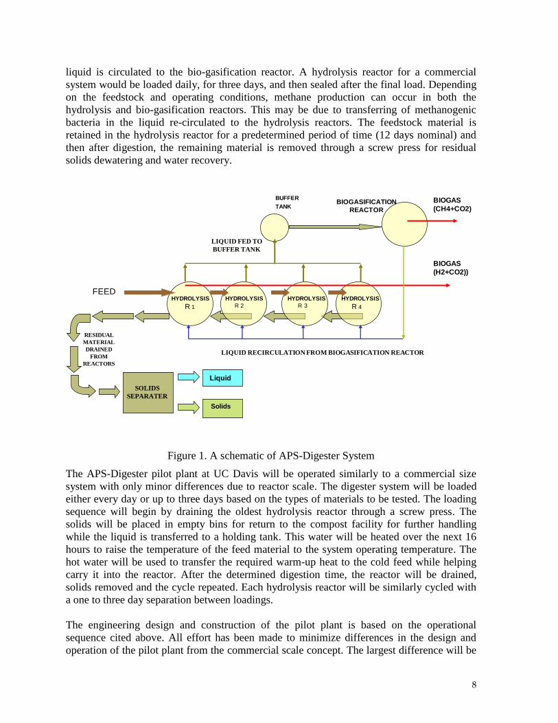
materials regardless of moisture content or physical characteristics. Figure 1 shows the
schematic of the APS-Digester System. The system is divided into two phases with a semi-
continuous circulation of liquid between the vessels. Feed material is loaded into the
hydrolysis reactor, acted on by extra-cellular enzymes and acidogenic bacteria, thereby
liquefied and converted to simple organic acids. These acids are transferred to the bio-
biogasification reactor, where they are converted further into biogas by methanogenic
bacteria. The biogas is a flammable mixture of methane (CH4) and carbon dioxide (CO2).
Multiple hydrolysis reactors allow for sequential loading such that each reactor is at a
different stage of acidogenesis. The combined organic acids remain relatively constant,
contributing to a level biogas production rate in the methanogenic reactor despite the batch
loading schedule.
The APS-Digester system is designed for the organic material to be loaded into one of
several hydrolysis reactors over a period of days. The nominal system operation is designed
for a 12-day retention time in each hydrolysis reactor. During nominal operation, one of the
four hydrolysis reactors is loaded and sealed every three days. The material is saturated with
pre-heated water and warmed to the operating temperature, digestion begins, and the reactor
8
liquid is circulated to the bio-gasification reactor. A hydrolysis reactor for a commercial
system would be loaded daily, for three days, and then sealed after the final load. Depending
on the feedstock and operating conditions, methane production can occur in both the
hydrolysis and bio-gasification reactors. This may be due to transferring of methanogenic
bacteria in the liquid re-circulated to the hydrolysis reactors. The feedstock material is
retained in the hydrolysis reactor for a predetermined period of time (12 days nominal) and
then after digestion, the remaining material is removed through a screw press for residual
solids dewatering and water recovery.
LIQUID RECIRCULATION FROM BIOGASIFICATION REACTOR
BUFFER
TANK
HYDROLYSIS
R 4
BIOGASIFICATION
REACTOR
HYDROLYSIS
R 2
HYDROLYSIS
R 3
HYDROLYSIS
R 1
Solids
Liquid
RESIDUAL
MATERIAL
DRAINED
FROM
REACTORS
SOLIDS
SEPARATER
LIQUID FED TO
BUFFER TANK
BIOGAS
(CH4+CO2)
FEED
BIOGAS
(H2+CO2))
Figure 1. A schematic of APS-Digester System
The APS-Digester pilot plant at UC Davis will be operated similarly to a commercial size
system with only minor differences due to reactor scale. The digester system will be loaded
either every day or up to three days based on the types of materials to be tested. The loading
sequence will begin by draining the oldest hydrolysis reactor through a screw press. The
solids will be placed in empty bins for return to the compost facility for further handling
while the liquid is transferred to a holding tank. This water will be heated over the next 16
hours to raise the temperature of the feed material to the system operating temperature. The
hot water will be used to transfer the required warm-up heat to the cold feed while helping
carry it into the reactor. After the determined digestion time, the reactor will be drained,
solids removed and the cycle repeated. Each hydrolysis reactor will be similarly cycled with
a one to three day separation between loadings.
The engineering design and construction of the pilot plant is based on the operational
sequence cited above. All effort has been made to minimize differences in the design and
operation of the pilot plant from the commercial scale concept. The largest difference will be
9
in the reactor heat loads. The surface area to volume ratio improves with larger tanks and will
result in decreased heat loss per reactor volume.
3. Pilot Digester Construction Specifications
The pilot digester plant was constructed on a concrete pad. Each sub-system is described
below with critical design criteria and operating parameters.
3.1. Concrete pad
A concrete pad was constructed to accommodate the pilot digester system. This area consists
of two sections, one that is 35 feet x 58 feet and an adjoining section that is 47 feet x 70 feet.
The larger section will be used to hold the material receiving, processing and residue
recovery equipment. A section of this area contains a sloped area that will allow the floor at
the back end of the roll-off to be level with the rest of the pad and allow a skid-steer to enter
the bin without a ramp. Typical roll-off bin floors are 8 inches off ground level. The
designated area is 21 feet x 20 feet. The sloped area begins 5 feet south of the north access
road and slopes down to the south for 20 feet to a drop of 5 inches. The sloped area begins 5
feet from the east side of the pad and continues 21 feet to the west.
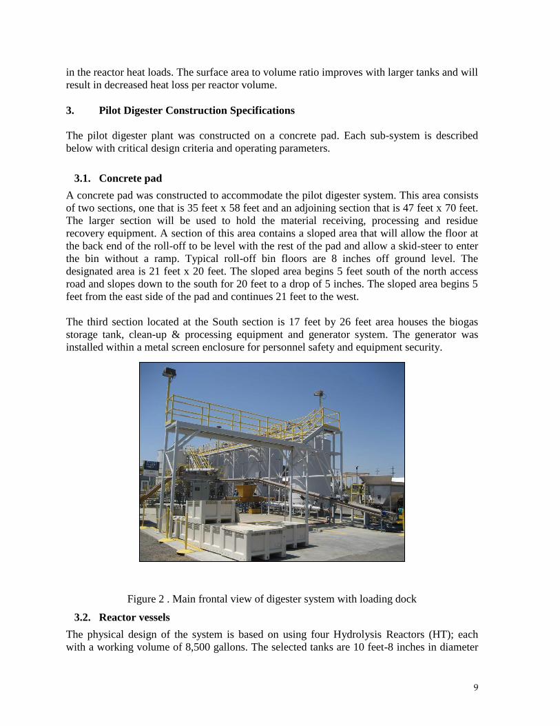
The third section located at the South section is 17 feet by 26 feet area houses the biogas
storage tank, clean-up & processing equipment and generator system. The generator was
installed within a metal screen enclosure for personnel safety and equipment security.
Figure 2 . Main frontal view of digester system with loading dock
3.2. Reactor vessels
The physical design of the system is based on using four Hydrolysis Reactors (HT); each
with a working volume of 8,500 gallons. The selected tanks are 10 feet-8 inches in diameter
10
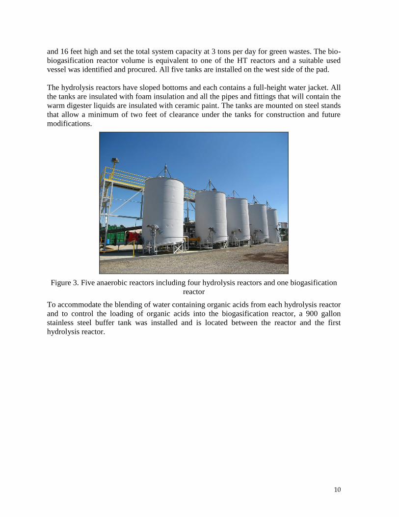
and 16 feet high and set the total system capacity at 3 tons per day for green wastes. The bio-
biogasification reactor volume is equivalent to one of the HT reactors and a suitable used
vessel was identified and procured. All five tanks are installed on the west side of the pad.
The hydrolysis reactors have sloped bottoms and each contains a full-height water jacket. All
the tanks are insulated with foam insulation and all the pipes and fittings that will contain the
warm digester liquids are insulated with ceramic paint. The tanks are mounted on steel stands
that allow a minimum of two feet of clearance under the tanks for construction and future
modifications.
Figure 3. Five anaerobic reactors including four hydrolysis reactors and one biogasification
reactor
To accommodate the blending of water containing organic acids from each hydrolysis reactor
and to control the loading of organic acids into the biogasification reactor, a 900 gallon
stainless steel buffer tank was installed and is located between the reactor and the first
hydrolysis reactor.
11
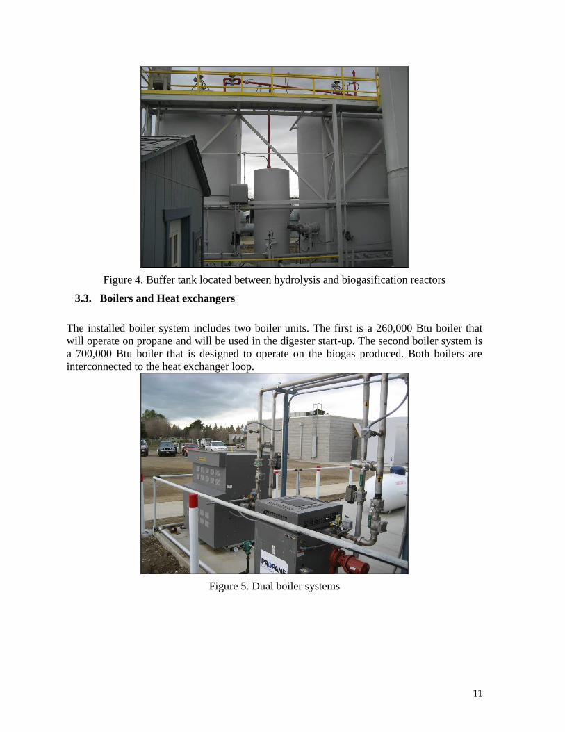
Figure 4. Buffer tank located between hydrolysis and biogasification reactors
3.3. Boilers and Heat exchangers
The installed boiler system includes two boiler units. The first is a 260,000 Btu boiler that
will operate on propane and will be used in the digester start-up. The second boiler system is
a 700,000 Btu boiler that is designed to operate on the biogas produced. Both boilers are
interconnected to the heat exchanger loop.
Figure 5. Dual boiler systems
12
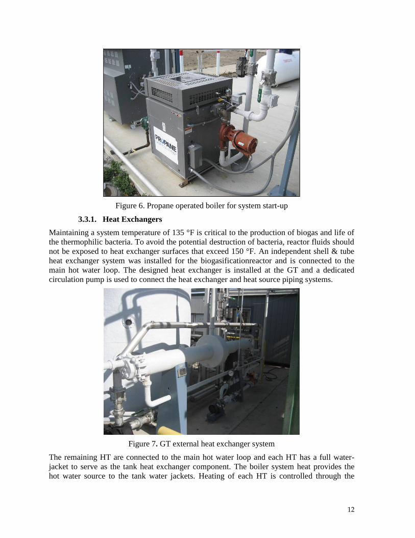
Figure 6. Propane operated boiler for system start-up
3.3.1. Heat Exchangers
Maintaining a system temperature of 135 °F is critical to the production of biogas and life of
the thermophilic bacteria. To avoid the potential destruction of bacteria, reactor fluids should
not be exposed to heat exchanger surfaces that exceed 150 °F. An independent shell & tube
heat exchanger system was installed for the biogasificationreactor and is connected to the
main hot water loop. The designed heat exchanger is installed at the GT and a dedicated
circulation pump is used to connect the heat exchanger and heat source piping systems.
Figure 7. GT external heat exchanger system
The remaining HT are connected to the main hot water loop and each HT has a full water-
jacket to serve as the tank heat exchanger component. The boiler system heat provides the
hot water source to the tank water jackets. Heating of each HT is controlled through the
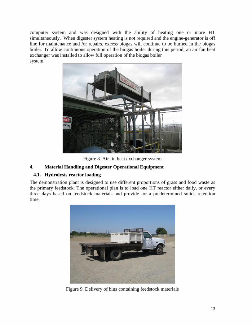
13
computer system and was designed with the ability of heating one or more HT
simultaneously. When digester system heating is not required and the engine-generator is off
line for maintenance and /or repairs, excess biogas will continue to be burned in the biogas
boiler. To allow continuous operation of the biogas boiler during this period, an air fan heat
exchanger was installed to allow full operation of the biogas boiler
system.
Figure 8. Air fin heat exchanger system
4. Material Handling and Digester Operational Equipment
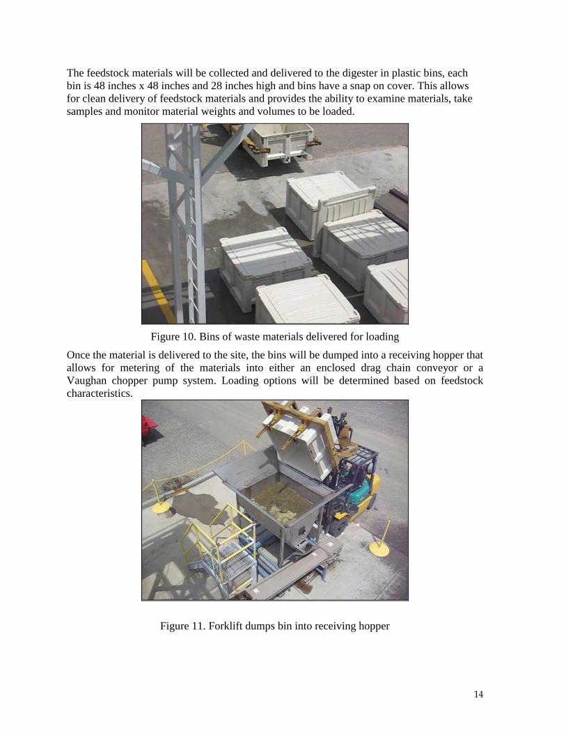
4.1. Hydrolysis reactor loading
The demonstration plant is designed to use different proportions of grass and food waste as
the primary feedstock. The operational plan is to load one HT reactor either daily, or every
three days based on feedstock materials and provide for a predetermined solids retention
time.
Figure 9. Delivery of bins containing feedstock materials
14
The feedstock materials will be collected and delivered to the digester in plastic bins, each
bin is 48 inches x 48 inches and 28 inches high and bins have a snap on cover. This allows
for clean delivery of feedstock materials and provides the ability to examine materials, take
samples and monitor material weights and volumes to be loaded.
Figure 10. Bins of waste materials delivered for loading
Once the material is delivered to the site, the bins will be dumped into a receiving hopper that
allows for metering of the materials into either an enclosed drag chain conveyor or a
Vaughan chopper pump system. Loading options will be determined based on feedstock
characteristics.
Figure 11. Forklift dumps bin into receiving hopper

15
Figure 12. Receiving hopper metering feedstock into conveyor system
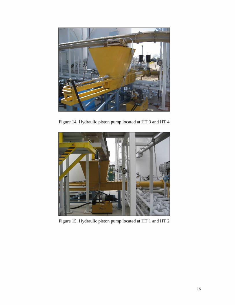
The conveyor system carries the material to two hydraulic piston pumps. One pump is
located between HT 1 and HT 2, the second pump is located between HT 3 and HT 4. The
conveyor discharges material into the selected hydraulic pump based on which HT is to be
loaded. Once the material is delivered to the piston pump; it is then loaded into the selected
HT.
Figure 13. Conveyor delivers feedstock to hydraulic piston pumps
16
Figure 14. Hydraulic piston pump located at HT 3 and HT 4
Figure 15. Hydraulic piston pump located at HT 1 and HT 2
17
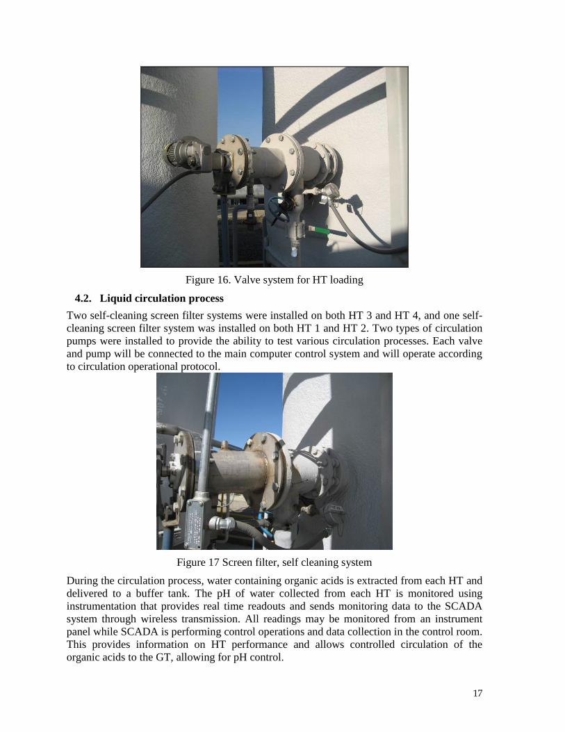
Figure 16. Valve system for HT loading
4.2. Liquid circulation process
Two self-cleaning screen filter systems were installed on both HT 3 and HT 4, and one self-
cleaning screen filter system was installed on both HT 1 and HT 2. Two types of circulation
pumps were installed to provide the ability to test various circulation processes. Each valve
and pump will be connected to the main computer control system and will operate according
to circulation operational protocol.
Figure 17 Screen filter, self cleaning system
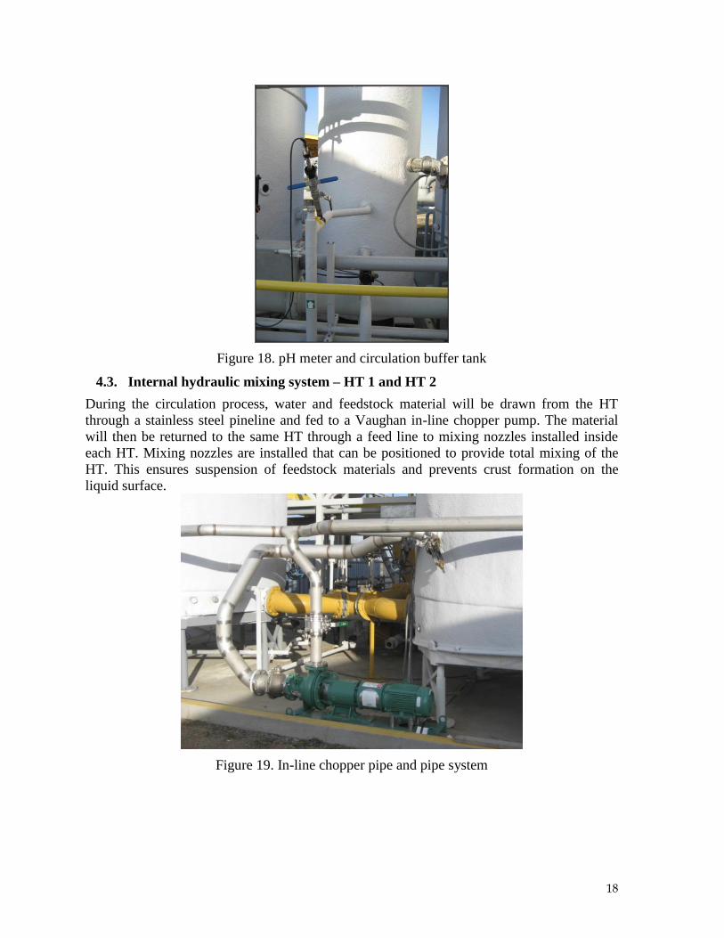
During the circulation process, water containing organic acids is extracted from each HT and
delivered to a buffer tank. The pH of water collected from each HT is monitored using
instrumentation that provides real time readouts and sends monitoring data to the SCADA
system through wireless transmission. All readings may be monitored from an instrument
panel while SCADA is performing control operations and data collection in the control room.
This provides information on HT performance and allows controlled circulation of the
organic acids to the GT, allowing for pH control.
18
Figure 18. pH meter and circulation buffer tank
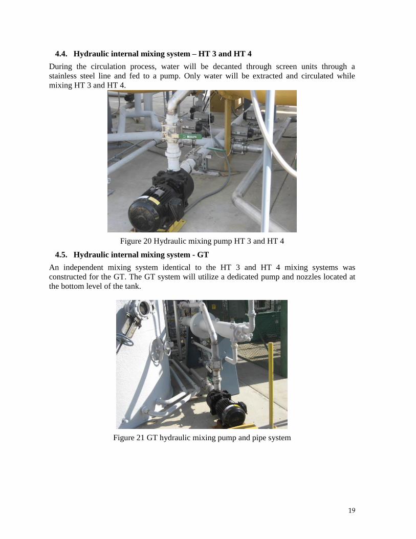
4.3. Internal hydraulic mixing system – HT 1 and HT 2
During the circulation process, water and feedstock material will be drawn from the HT
through a stainless steel pineline and fed to a Vaughan in-line chopper pump. The material
will then be returned to the same HT through a feed line to mixing nozzles installed inside
each HT. Mixing nozzles are installed that can be positioned to provide total mixing of the
HT. This ensures suspension of feedstock materials and prevents crust formation on the
liquid surface.
Figure 19. In-line chopper pipe and pipe system
19
4.4. Hydraulic internal mixing system – HT 3 and HT 4
During the circulation process, water will be decanted through screen units through a
stainless steel line and fed to a pump. Only water will be extracted and circulated while
mixing HT 3 and HT 4.
Figure 20 Hydraulic mixing pump HT 3 and HT 4
4.5. Hydraulic internal mixing system - GT
An independent mixing system identical to the HT 3 and HT 4 mixing systems was
constructed for the GT. The GT system will utilize a dedicated pump and nozzles located at
the bottom level of the tank.
Figure 21 GT hydraulic mixing pump and pipe system
20
Each circulation pump has a dedicated drive installed that is either manually operated or
operated through the main computer control system. Each air actuated valve has been
connected to the main computer control system and will be operated according to the
designated operational protocol. A main air controller system was installed inside the
computer control building.
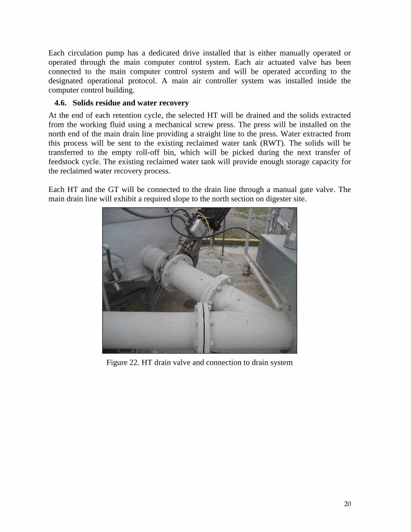
4.6. Solids residue and water recovery
At the end of each retention cycle, the selected HT will be drained and the solids extracted
from the working fluid using a mechanical screw press. The press will be installed on the
north end of the main drain line providing a straight line to the press. Water extracted from
this process will be sent to the existing reclaimed water tank (RWT). The solids will be
transferred to the empty roll-off bin, which will be picked during the next transfer of
feedstock cycle. The existing reclaimed water tank will provide enough storage capacity for
the reclaimed water recovery process.
Each HT and the GT will be connected to the drain line through a manual gate valve. The
main drain line will exhibit a required slope to the north section on digester site.
Figure 22. HT drain valve and connection to drain system

21
Figure 23. Drain section to be connected to pump and screw press unit
A trash pump will be installed at the end of the drain system to meter the flow of water and
materials into the material recovery system. Just after the trash-pump, the drain line will
connect to a screw press. It was determined that the press will provide solids with a moisture
content that will not drip liquid when transferred to the roll-off box. The water recovery drain
from the screw press will be routed to the RWT through a stainless steel pipe system. A
secondary water line from the RWT will be connected to the south end of the main 8-inch
drain line to provide the ability to flush out the feed/drain system into the press in a closed
loop water transfer cycle.
4.7. Tank pressure/vacuum equalization
To assure that all tanks remain at their design pressure or vacuum, their head pressures are
equalized when fluid is transferred from one tank to another. To accomplish this, each tank’s
head space is connected via the biogas collection system piping. Pressure transducers have
been installed on each digester tank and will be monitored by the computer control system.
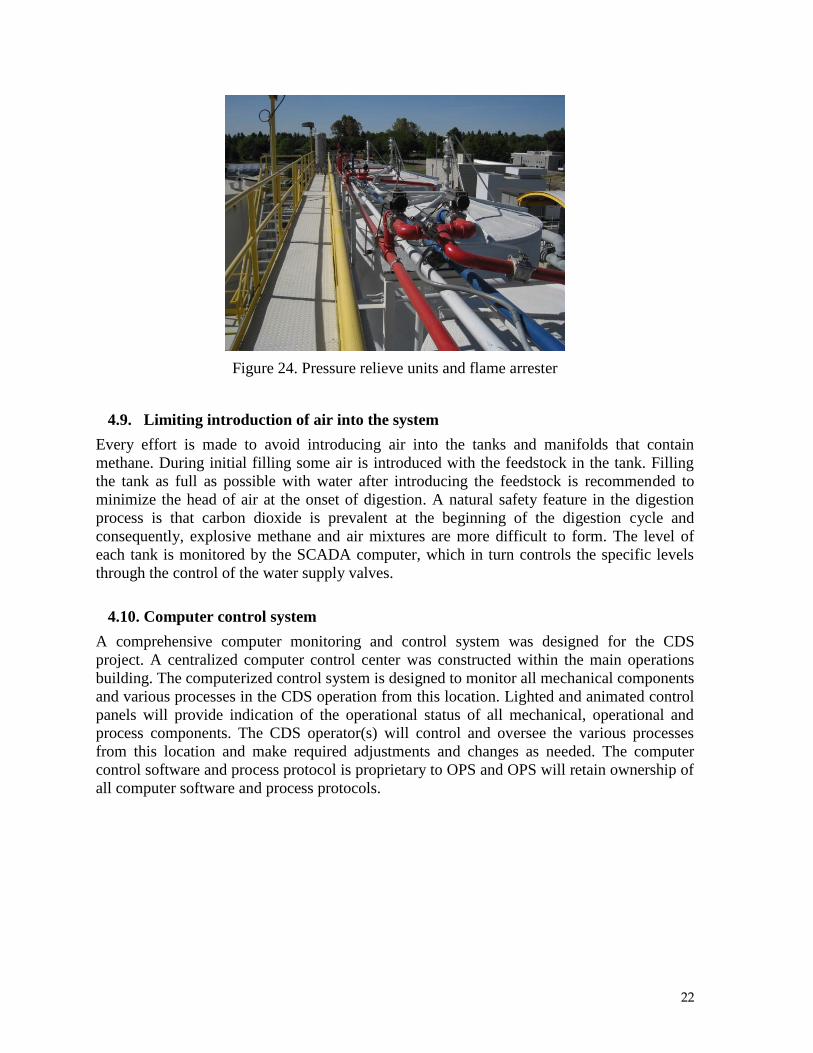
4.8. Safety pressure relief valve
Over-pressure and vacuum limitations are designed through the installation of a spring-
loaded valve in the top of each tank. These specially designed valves do not allow the tank to
exceed safe operating pressures or vacuums. Venting of the tank occurs if the pressure
exceeds 54-inches of water column. As an additional safety factor, a flame arrester has been
installed on each digester reactor.
22
Figure 24. Pressure relieve units and flame arrester
4.9. Limiting introduction of air into the system
Every effort is made to avoid introducing air into the tanks and manifolds that contain
methane. During initial filling some air is introduced with the feedstock in the tank. Filling
the tank as full as possible with water after introducing the feedstock is recommended to
minimize the head of air at the onset of digestion. A natural safety feature in the digestion
process is that carbon dioxide is prevalent at the beginning of the digestion cycle and
consequently, explosive methane and air mixtures are more difficult to form. The level of
each tank is monitored by the SCADA computer, which in turn controls the specific levels
through the control of the water supply valves.
4.10. Computer control system
A comprehensive computer monitoring and control system was designed for the CDS
project. A centralized computer control center was constructed within the main operations
building. The computerized control system is designed to monitor all mechanical components
and various processes in the CDS operation from this location. Lighted and animated control
panels will provide indication of the operational status of all mechanical, operational and
process components. The CDS operator(s) will control and oversee the various processes
from this location and make required adjustments and changes as needed. The computer
control software and process protocol is proprietary to OPS and OPS will retain ownership of
all computer software and process protocols.
23
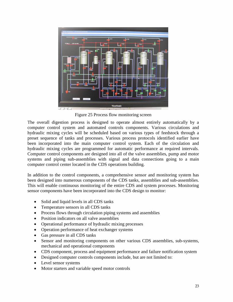
Figure 25 Process flow monitoring screen
The overall digestion process is designed to operate almost entirely automatically by a
computer control system and automated controls components. Various circulations and
hydraulic mixing cycles will be scheduled based on various types of feedstock through a
preset sequence of tanks and processes. Various process protocols identified earlier have
been incorporated into the main computer control system. Each of the circulation and
hydraulic mixing cycles are programmed for automatic performance at required intervals.
Computer control components are designed into all of the valve assemblies, pump and motor
systems and piping sub-assemblies with signal and data connections going to a main
computer control center located in the CDS operations building.
In addition to the control components, a comprehensive sensor and monitoring system has
been designed into numerous components of the CDS tanks, assemblies and sub-assemblies.
This will enable continuous monitoring of the entire CDS and system processes. Monitoring
sensor components have been incorporated into the CDS design to monitor:
Solid and liquid levels in all CDS tanks
Temperature sensors in all CDS tanks
Process flows through circulation piping systems and assemblies
Position indicators on all valve assemblies
Operational performance of hydraulic mixing processes
Operation performance of heat exchanger systems
Gas pressure in all CDS tanks
Sensor and monitoring components on other various CDS assemblies, sub-systems,
mechanical and operational components
CDS component, process and equipment performance and failure notification system
Designed computer controls components include, but are not limited to:
Level sensor systems
Motor starters and variable speed motor controls
24
Valve assembly relays and position indicators
Air operational controls components
ADS processes control and operational components
Safety system valves, pressure relief and emergency operational sensors and
components
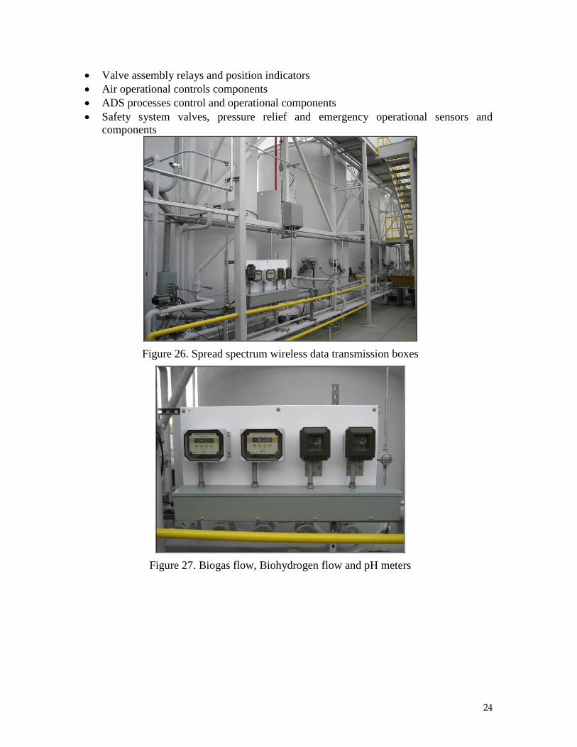
Figure 26. Spread spectrum wireless data transmission boxes
Figure 27. Biogas flow, Biohydrogen flow and pH meters
25
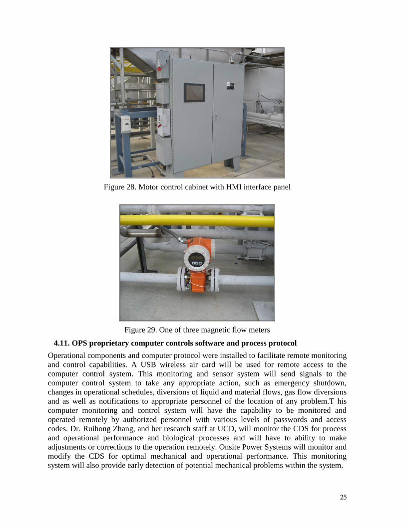
Figure 28. Motor control cabinet with HMI interface panel
Figure 29. One of three magnetic flow meters
4.11. OPS proprietary computer controls software and process protocol
Operational components and computer protocol were installed to facilitate remote monitoring
and control capabilities. A USB wireless air card will be used for remote access to the
computer control system. This monitoring and sensor system will send signals to the
computer control system to take any appropriate action, such as emergency shutdown,
changes in operational schedules, diversions of liquid and material flows, gas flow diversions
and as well as notifications to appropriate personnel of the location of any problem.T his
computer monitoring and control system will have the capability to be monitored and
operated remotely by authorized personnel with various levels of passwords and access
codes. Dr. Ruihong Zhang, and her research staff at UCD, will monitor the CDS for process
and operational performance and biological processes and will have to ability to make
adjustments or corrections to the operation remotely. Onsite Power Systems will monitor and
modify the CDS for optimal mechanical and operational performance. This monitoring
system will also provide early detection of potential mechanical problems within the system.
26
5. Biogas Collection and Processing System
As a project requirement, the daily production of biogas will be measured and recorded. The
chemical composition of the biogas will be measured periodically by taking gas samples
from ports installed in the hydrolysis and biogasificationreactor biogas collection lines and
analyzing them with a gas chromatograph (GC). A detailed gas analysis will be used to verify
measured readings and gas composition through the periodic collection and analysis of
samples. Additionally, a gas flow meter will continually monitor the gas production and
record the values at a central supervisory control and data acquisition (SCADA) computer.
5.1. Biogas collection
Each reactor vessel in the system will generate biogas. The biogas quantity and composition
will vary as the digestion process progresses though each cycle. In the early stages of
decomposition, primarily carbon dioxide is generated in the hydrolysis reactors. As time
progresses, the methane content of the biogas increases to approximately 60 to 70% by
volume. As the hydrolysis reactors are sequentially batch loaded, each will exhibit a different
gas composition, while the biogas generated in the bio-gasification reactor remains relatively
constant.
To assure the proper operation of the engine fuelled by the biogas, it is necessary to achieve a
relatively constant volume and quality of biogas throughout the process. This is achieved by
mixing the biogas output from each reactor into a common manifold.
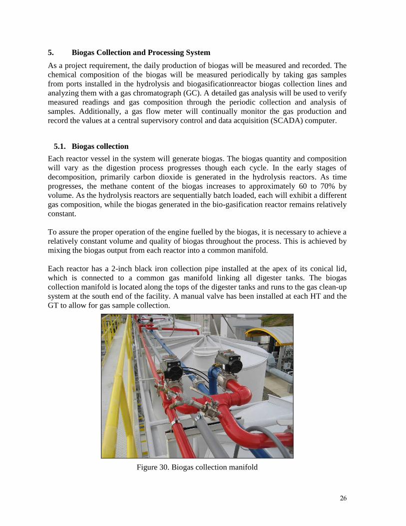
Each reactor has a 2-inch black iron collection pipe installed at the apex of its conical lid,
which is connected to a common gas manifold linking all digester tanks. The biogas
collection manifold is located along the tops of the digester tanks and runs to the gas clean-up
system at the south end of the facility. A manual valve has been installed at each HT and the
GT to allow for gas sample collection.
Figure 30. Biogas collection manifold
27
Each hydrolysis reactor has valves controlled by SCADA to isolate reactors from
biohydrogen (blue pipe) and biomethane (red pipe). Any reactor may be isolated from other
reactors. All reactors are normally open to each other allowing pressure equalization during
filling and emptying operations.
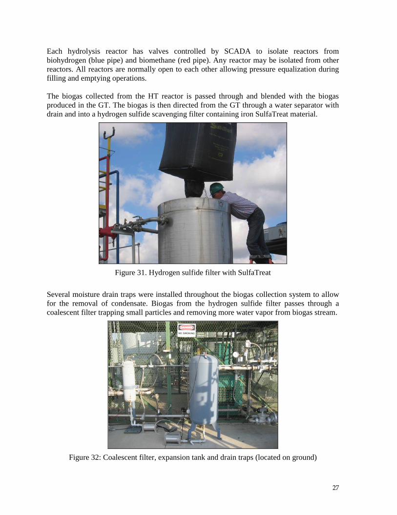
The biogas collected from the HT reactor is passed through and blended with the biogas
produced in the GT. The biogas is then directed from the GT through a water separator with
drain and into a hydrogen sulfide scavenging filter containing iron SulfaTreat material.
Figure 31. Hydrogen sulfide filter with SulfaTreat
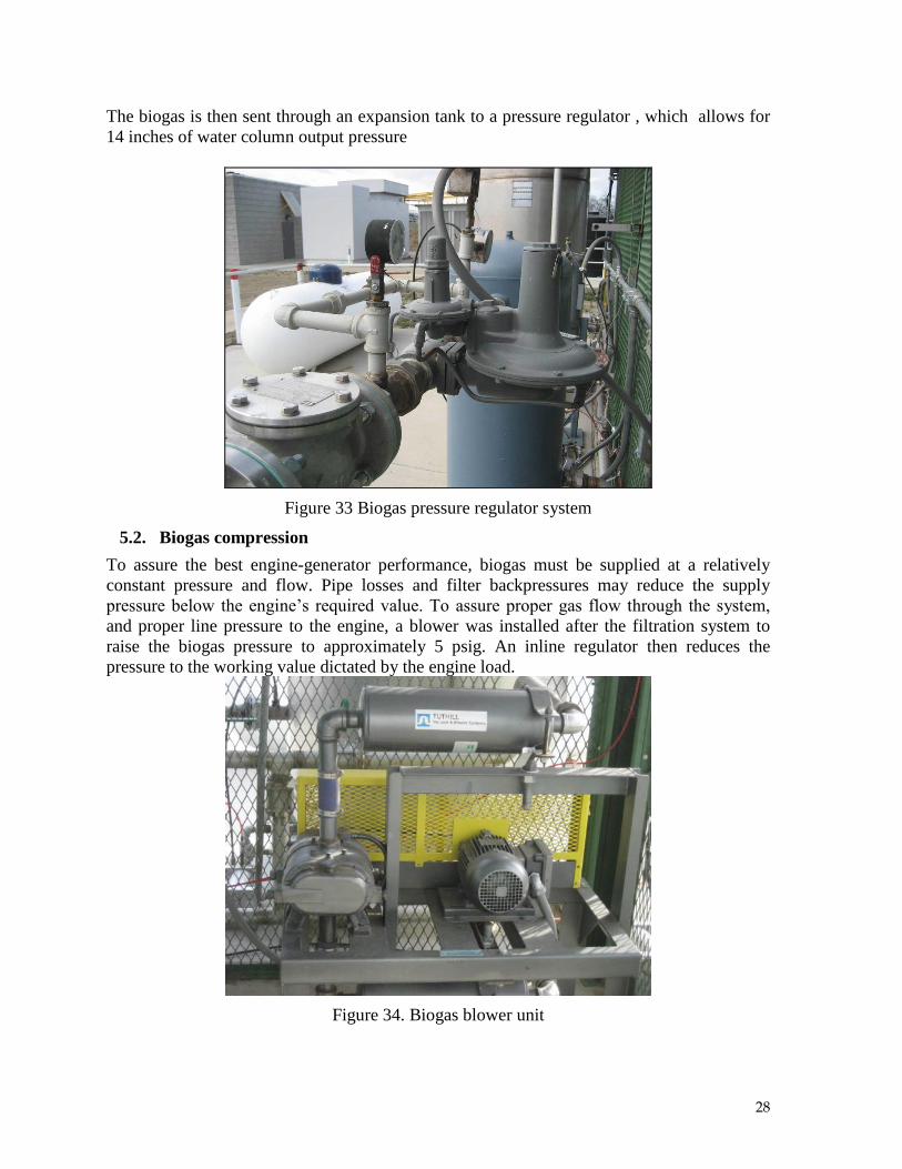
Several moisture drain traps were installed throughout the biogas collection system to allow
for the removal of condensate. Biogas from the hydrogen sulfide filter passes through a
coalescent filter trapping small particles and removing more water vapor from biogas stream.
Figure 32: Coalescent filter, expansion tank and drain traps (located on ground)
28
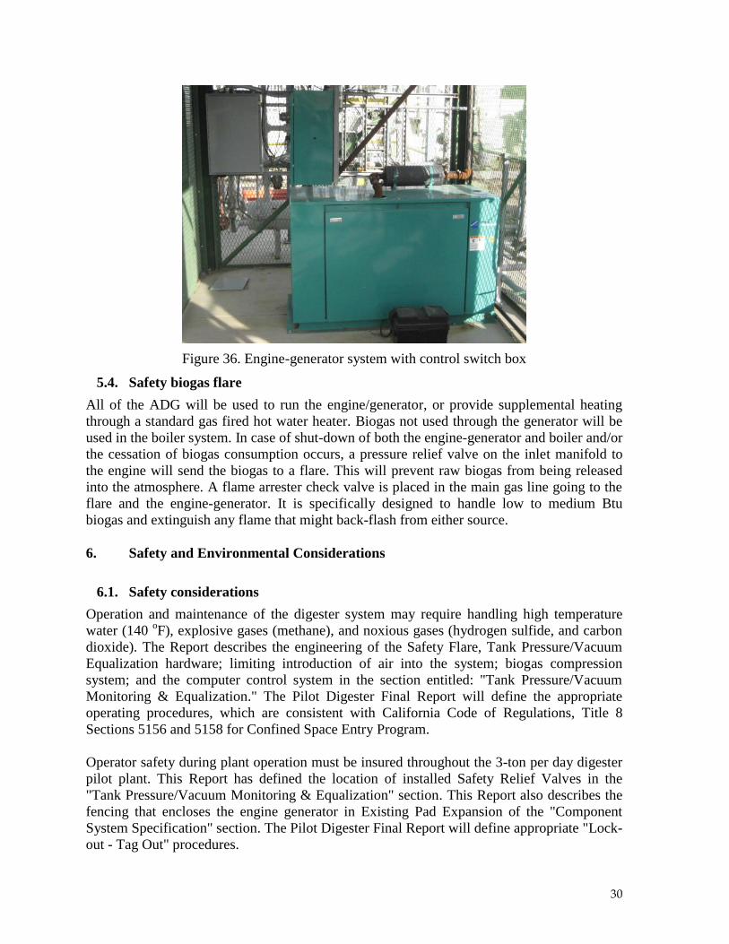
The biogas is then sent through an expansion tank to a pressure regulator , which allows for
14 inches of water column output pressure
Figure 33 Biogas pressure regulator system
5.2. Biogas compression
To assure the best engine-generator performance, biogas must be supplied at a relatively
constant pressure and flow. Pipe losses and filter backpressures may reduce the supply
pressure below the engine’s required value. To assure proper gas flow through the system,
and proper line pressure to the engine, a blower was installed after the filtration system to
raise the biogas pressure to approximately 5 psig. An inline regulator then reduces the
pressure to the working value dictated by the engine load.
Figure 34. Biogas blower unit

29
5.3. Electrical generator
One of the primary goals of the project is to generate electricity from the produced biogas. It
will be considered a design goal to deliver about 22 kW (528 kWh per day) of electric energy
to the grid. The electrical energy delivered to the grid will be measured by the
instrumentation and metering equipment installed on the Cummins generator system .
The generator system will be operated on a full-time basis when feasible, but may not
continuously provide power to the project. During demonstrations or daily operations, the
material processing and loading equipment may be operated using power from the generator
and / or the electric grid. The nominal electrical generating capacity of the system is
anticipated to be 528 kWh per day, with some reduction as required to meet thermal loads
during peak heat requirements.
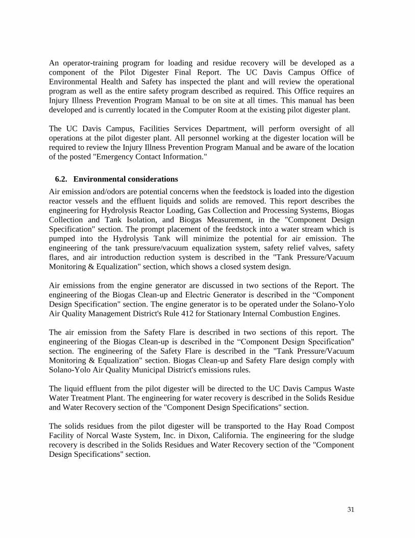
Figure 35. Engine-generator system with control switch box
30
Figure 36. Engine-generator system with control switch box
5.4. Safety biogas flare
All of the ADG will be used to run the engine/generator, or provide supplemental heating
through a standard gas fired hot water heater. Biogas not used through the generator will be
used in the boiler system. In case of shut-down of both the engine-generator and boiler and/or
the cessation of biogas consumption occurs, a pressure relief valve on the inlet manifold to
the engine will send the biogas to a flare. This will prevent raw biogas from being released
into the atmosphere. A flame arrester check valve is placed in the main gas line going to the
flare and the engine-generator. It is specifically designed to handle low to medium Btu
biogas and extinguish any flame that might back-flash from either source.
6. Safety and Environmental Considerations
6.1. Safety considerations
Operation and maintenance of the digester system may require handling high temperature
water (140 oF), explosive gases (methane), and noxious gases (hydrogen sulfide, and carbon
dioxide). The Report describes the engineering of the Safety Flare, Tank Pressure/Vacuum
Equalization hardware; limiting introduction of air into the system; biogas compression
system; and the computer control system in the section entitled: "Tank Pressure/Vacuum
Monitoring & Equalization." The Pilot Digester Final Report will define the appropriate
operating procedures, which are consistent with California Code of Regulations, Title 8
Sections 5156 and 5158 for Confined Space Entry Program.
Operator safety during plant operation must be insured throughout the 3-ton per day digester
pilot plant. This Report has defined the location of installed Safety Relief Valves in the
"Tank Pressure/Vacuum Monitoring & Equalization" section. This Report also describes the
fencing that encloses the engine generator in Existing Pad Expansion of the "Component
System Specification" section. The Pilot Digester Final Report will define appropriate "Lock-
out - Tag Out" procedures.
31
An operator-training program for loading and residue recovery will be developed as a
component of the Pilot Digester Final Report. The UC Davis Campus Office of
Environmental Health and Safety has inspected the plant and will review the operational
program as well as the entire safety program described as required. This Office requires an
Injury Illness Prevention Program Manual to be on site at all times. This manual has been
developed and is currently located in the Computer Room at the existing pilot digester plant.
The UC Davis Campus, Facilities Services Department, will perform oversight of all
operations at the pilot digester plant. All personnel working at the digester location will be
required to review the Injury Illness Prevention Program Manual and be aware of the location
of the posted "Emergency Contact Information."
6.2. Environmental considerations
Air emission and/odors are potential concerns when the feedstock is loaded into the digestion
reactor vessels and the effluent liquids and solids are removed. This report describes the
engineering for Hydrolysis Reactor Loading, Gas Collection and Processing Systems, Biogas
Collection and Tank Isolation, and Biogas Measurement, in the "Component Design
Specification" section. The prompt placement of the feedstock into a water stream which is
pumped into the Hydrolysis Tank will minimize the potential for air emission. The
engineering of the tank pressure/vacuum equalization system, safety relief valves, safety
flares, and air introduction reduction system is described in the "Tank Pressure/Vacuum
Monitoring & Equalization" section, which shows a closed system design.
Air emissions from the engine generator are discussed in two sections of the Report. The
engineering of the Biogas Clean-up and Electric Generator is described in the “Component
Design Specification" section. The engine generator is to be operated under the Solano-Yolo
Air Quality Management District's Rule 412 for Stationary Internal Combustion Engines.
The air emission from the Safety Flare is described in two sections of this report. The
engineering of the Biogas Clean-up is described in the “Component Design Specification"
section. The engineering of the Safety Flare is described in the "Tank Pressure/Vacuum
Monitoring & Equalization" section. Biogas Clean-up and Safety Flare design comply with
Solano-Yolo Air Quality Municipal District's emissions rules.
The liquid effluent from the pilot digester will be directed to the UC Davis Campus Waste
Water Treatment Plant. The engineering for water recovery is described in the Solids Residue
and Water Recovery section of the "Component Design Specifications" section.
The solids residues from the pilot digester will be transported to the Hay Road Compost
Facility of Norcal Waste System, Inc. in Dixon, California. The engineering for the sludge
recovery is described in the Solids Residues and Water Recovery section of the "Component
Design Specifications" section.
32
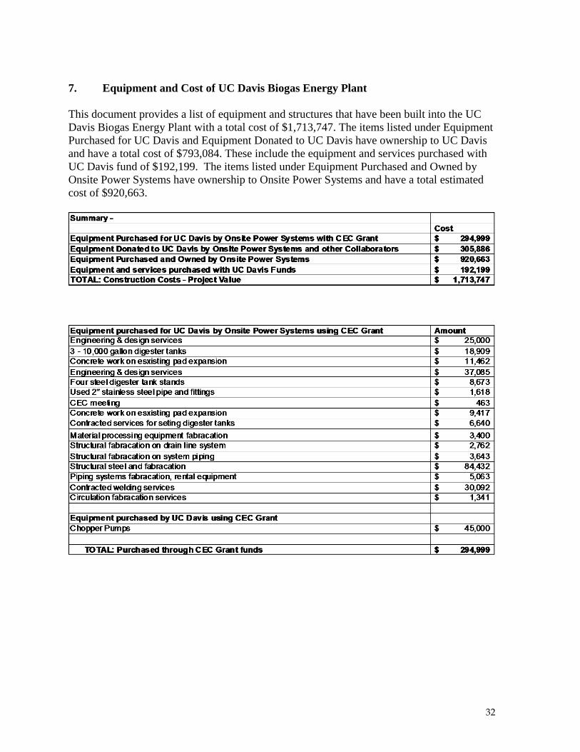
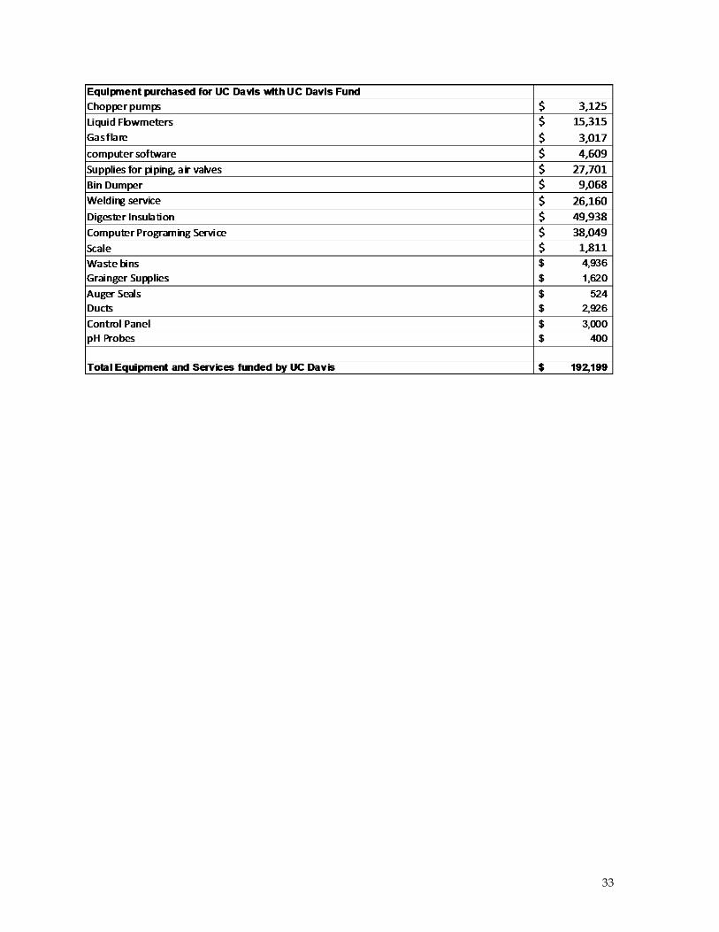
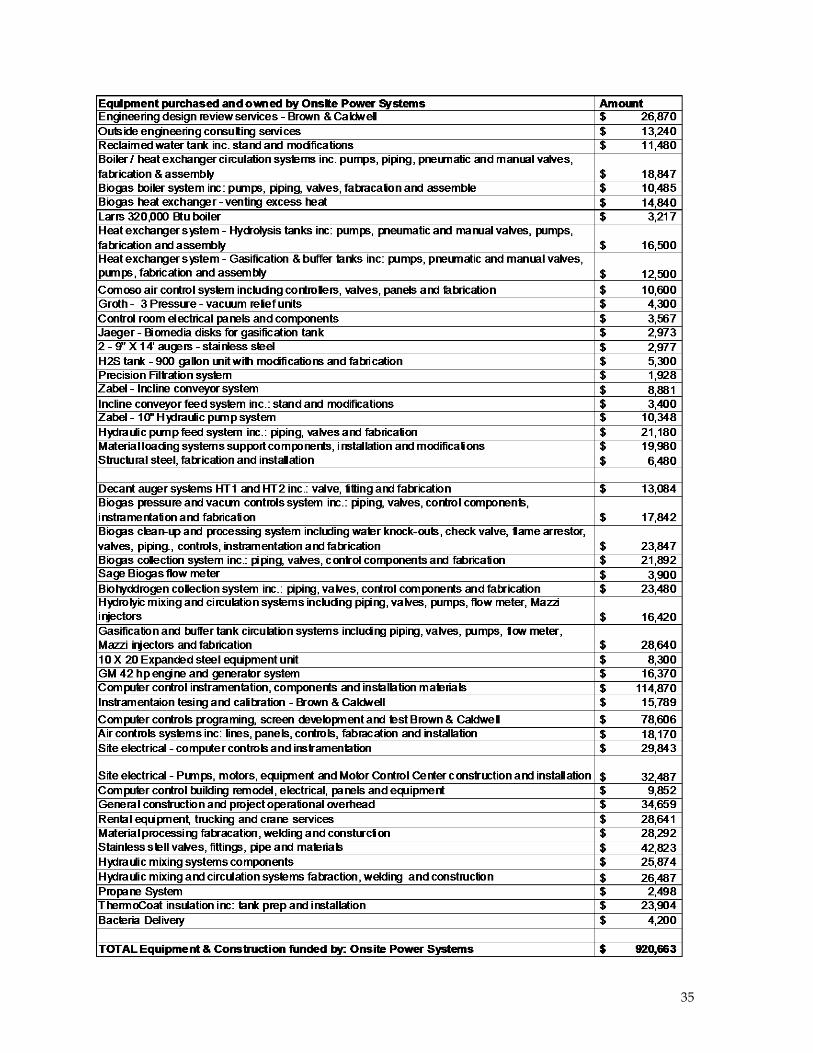
7. Equipment and Cost of UC Davis Biogas Energy Plant
This document provides a list of equipment and structures that have been built into the UC
Davis Biogas Energy Plant with a total cost of $1,713,747. The items listed under Equipment
Purchased for UC Davis and Equipment Donated to UC Davis have ownership to UC Davis
and have a total cost of $793,084. These include the equipment and services purchased with
UC Davis fund of $192,199. The items listed under Equipment Purchased and Owned by
Onsite Power Systems have ownership to Onsite Power Systems and have a total estimated
cost of $920,663.
33

34
35
36
8. References
US Patent 6,342,378. Biogasification of Solid Wastes by Anaerobic Phased Solids Digester
System. Issued in January, 2002. Inventors: Zhang, R.H. and Z. Zhang
Zhang, R.H., D. Konwinski, K. Hartman, S. Archibald, H. El-Mashed, G. Matteson. 2005.
Anaerobic Phased Solids Digester Demonstration Project – Pilot Digester Design and Test
Plan. Report submitted to Public Interest Energy Research (PIER) program of California
Energy Commission. March 2005.
9. Acknowledgement
The capital for design and construction of the pilot digester system is provided by the
research grants from California Energy Commission and University of California, Davis and
in-kind and cash funds provided by Onsite Power Systems.
APS-Digester Design and Development Team Members
Onsite Power Systems
Dave Konwinski (President)
Scott Archibald (CEO)
University of California, Davis
Ruihong Zhang (Principal Investigator)
Hamed El-Mashad (Post Doctoral Researcher)
Josh Rapport (Graduate Research Assistant)
Iain Clark (Graduate Research Assistant)
The following companies have made contributions to the design, development and
construction of the digester project.
Brown and Caldwell (Computer controls design)
Rockwell Engineering (Material processing and hydraulic mixing)
Mazzie Injectors (Hydraulic mixing)
Kouba Engineering (Engineering design review)
GraybaR (Instrumentation and controls components)
Advanced Food Technologies (Material processing equipment and design)
Wonderware (Computer control and data collection programs)
37
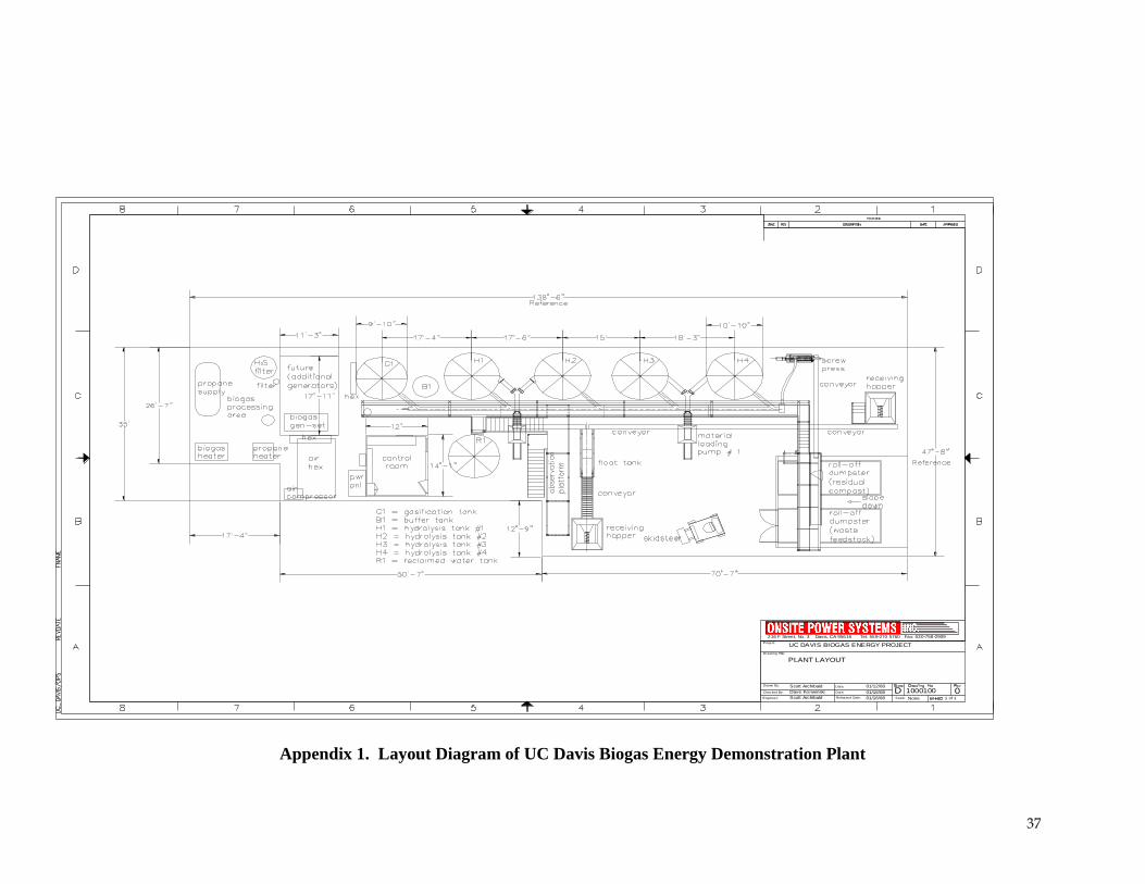
PLANT LAYOUT
216 F Street, No. 3 Davis, CA 95616 Tel: 559-270 5760 Fax: 530-758-2909
Drawn By: Scott Archibald
UC DAVIS BIOGAS ENERGY PROJECT
1000100NoneScale: 1 of 1
0DDave KonwinskiChecked By:
Released Date:
Date: 01/12/08
01/16/08
01/16/08Date:
Engineer: Scott Archibald
Drawing Title:
Project:
Appendix 1. Layout Diagram of UC Davis Biogas Energy Demonstration Plant