an4349, adding device(s) to the codewarrior flash programmer for
TRANSCRIPT
© Freescale Semiconductor, Inc., 2014. All rights reserved.
Freescale Semiconductor Document Number: AN4349
Application Note
Adding Device(s) to the CodeWarrior™
Flash Programmer for ARM™ V7
1. Introduction
This document explains how to add support for
additional flash devices on the Flash Programmer for
CodeWarrior™ Development Studio for QorIQ LS
series - ARM V7 ISA by using the Flash Tool Kit. To
add support for a new flash device, you need to write a
new flash programming algorithm and create some
supporting files.
This document explains:
• Creating a flash device XML configuration file
• Creating a new target task
• Creating an external flash algorithm
• Creating a new flash utility
• Troubleshooting flash programmer
2. Preliminary Background
Before you program or erase any flash device, you must
ensure that the CPU can access it. For example, you
might need a different debug setup that requires
modifications to the debugger configuration file.
Consider the following before you begin:
• Read the flash device ID to verify correct
Contents
1. Introduction ............................................................... 1
2. Preliminary Background ........................................... 1
3. Flash Tool Kit (FTK) Overview ................................ 2
4. Creating Flash Device XML Configuration File ....... 2
5. Creating New Target Task ...................................... 12
6. Creating External Flash Algorithm ......................... 23
7. Creating New Flash Utility ..................................... 37
8. Troubleshooting Flash Programmer ........................ 45
Flash Tool Kit (FTK) Overview
Adding Device(s) to the CodeWarrior™ Flash Programmer for ARM™ V7
2 Freescale Semiconductor
connection and programmability. See Troubleshooting Flash Programmer section for
instructions.
• Many manufacturers use the same flash-device algorithms, so it is likely that flashes can be
programmed using algorithms included with the CodeWarrior software.
• Check whether a new flash device can be programmed with an algorithm already included with
the CodeWarrior software, as described in Select Flash Programming Algorithm section.
• Follow the steps provided in Creating External Flash Algorithm section if the flash device cannot
be programmed with an existing algorithm.
3. Flash Tool Kit (FTK) Overview
To add support for a new flash device, you may need to create some or all of the following:
• An XML configuration file for the new device that describes organization, which is combination
of device size, bus width, and number of devices present on the board
• An XML configuration file for the board that specifies the flash device it must use, and tells
where the RAM memory is located
• A flash device algorithm if none of the existing algorithms are compatible
4. Creating Flash Device XML Configuration File
In its default configuration, the CodeWarrior™ Flash Programmer supports many flash devices. The
configuration files are located at: {CodeWarrior}\ARMv7\bin\plugins\support\Products\ProductData\FPDevice
s.mwpdb\FP
To add a new device to the CodeWarrior Flash Programmer, you must add a new file that describes the
device.
Listing 1 shows the file format.
Listing 1. Generic flash device file format
<device-file>
<device>
<content>
<name>NameOfFlashDevice</name>
<manufacturerid>MfgID</manufacturerid>
<chiperase>TRUE or FALSE</chiperase>
<sectors>
<sectorcount>NumberOfSectors</sectorcount>
<sectorsize>SectorSize</sectorsize>
.
.
<sectorcount>NumberOfSectors</sectorcount>
<sectorsize>SectorSize</sectorsize>

Creating Flash Device XML Configuration File
Adding Device(s) to the CodeWarrior™ Flash Programmer for ARM™ V7
Freescale Semiconductor 3
</sectors>
<organization>
<name>Capacity/BusWidth/NumberOfDevices</name>
<id>DeviceID_ForBusWidth</id>
<algorithm>FlashAlgorithmForVariant</algorithm>
<utility>FlashUtilityForVariant</utility>
</organization>
.
.
<organization>
<name>Capacity/BusWidth/NumberOfDevices</name>
<id>DeviceID_ForBusWidth</id>
<algorithm>FlashAlgorithmForVariant</algorithm>
<utility>FlashUtilityForVariant</utility>
</organization>
</content>
</device>
</device-file>
To add flash programming support for a new flash device:
1. Locate the data sheet for the new device and note the following information about the flash
device:
Device name
Manufacturer ID code
Device ID codes (8-bit, 16-bit)
Number of sectors
Starting and ending address for each sector
Whether the device can be chip erased
Options for data bits per device (8-bits, 16-bits)
Number of flash devices on target
Which device is most similar in the device configurations
2. Examine the installed devices for the most similar definitions.
3. Copy/edit the definition to make the XML device files conform to the new device.
4.1. Device Name
This is a free-form text field that describes the flash device, taken directly from the data sheet. Use only
displayable ASCII characters with no spaces. Some examples, found in the configurations folder are:
N25Q128A, JS28F00AM29EWHA, etc.
The format is: <name>NameOfFlashDevice</name>
Creating Flash Device XML Configuration File
Adding Device(s) to the CodeWarrior™ Flash Programmer for ARM™ V7
4 Freescale Semiconductor
4.2. Manufacturer ID and Device ID Codes
The Manufacturer ID and Device ID codes are read from the flash device after a specific sequence of
writes to the flash device. Although the data sheet lists both IDs, only the Device ID varies among the
flash devices from a given vendor, the Manufacturer ID remains the same. If the flash device supports
more than one bus width (8-bit, 16-bit), then it might have different Device ID for each mode.
The formats are:
<manufacturerid>MfgID</manufacturerid>
<id>DeviceID_ForBusWidth</id>
4.3. Chip Erasing
Some devices can be completely erased with one chip erase command and this is much faster than
erasing the device, sector by sector. Set the chip erase value to TRUE if your flash device supports this
feature.
The format is:
<chiperase>TRUE or FALSE</chiperase>
4.4. Number of Sectors and Sector Size
The data sheet lists the information about number of sectors and sector size. If the data sheet lists sector
maps and tables for both 8-bit and 16-bit data options, use the 8-bit data option. The CodeWarrior flash
programming algorithms require byte-level addresses for each sector. This constraint simplifies the
design of the CodeWarrior flash programming interface for several data-bus configurations and sizes.
When the data sheet does not provide a byte-level address, the algorithm creates an 8-bit sector map for
16-, 32-, or 64-bit devices. Table 1 shows an example of converting a 16-bit sector map to an 8-bit map.
The formats are:
<sectorcount>NumberOfSectors</sectorcount>
<sectorsize>SectorSize</sectorsize>
The sectorcount value is decimal while the sectorsize is hexadecimal.
For example, for a device that has eight (8) sectors of 0x2000 bytes, each followed by 30 sectors of
0x10000 bytes and another eight (8) sectors of 0x2000.
The configuration file will contain:
Creating Flash Device XML Configuration File
Adding Device(s) to the CodeWarrior™ Flash Programmer for ARM™ V7
Freescale Semiconductor 5
<sectors>
<sectorcount>8</sectorcount>
<sectorsize>2000</sectorsize>
<sectorcount>30</sectorcount>
<sectorsize>10000</sectorsize>
<sectorcount>8</sectorcount>
<sectorsize>2000</sectorsize>
</sectors>
Table 1. Sector Map Conversion
16-bit Sector Map (64K word sectors) 8-bit Sector Map (128Kbyte sectors)
000000..00FFFF 00000..01FFFF
010000..01FFFF 20000..03FFFF
020000..02FFFF 40000..05FFFF
030000..03FFFF 60000..07FFFF
Older flash devices can have sectors of different sizes. If you use such an older device, ensure that each
sector in the configuration file is of the correct size.
4.5. Organization Name Options
The information that must be specified here as an organization name includes: device size, bus width,
and number of devices present on the board.
Device size is the size of the device. It can be expressed as KB or MB using K and M suffixes.
Examples: 128K, 1M.
Many flash devices can be set to use either 8-data bits or 16-data bits depending on the status of a
configuration pin (typically named BYTE#) on each device. The <organization> field uses this part of
the flash definition, as described in the next paragraph. Your target uses only one configuration so you
need to support only that configuration. Expanding your new definition to include the other
configurations for this device, however, is a good design practice.
Your target may use one, two, or four devices at the same base address to support an 8-bit, 16-bit, 32-bit,
or 64-bit data bus.
Creating Flash Device XML Configuration File
Adding Device(s) to the CodeWarrior™ Flash Programmer for ARM™ V7
6 Freescale Semiconductor
For example, two 8-bit flash devices side by side support a 16-bit data bus, and four 16-bit devices
support a 64-bit data bus. The <organization> field summarizes each possible combination of device
capacity, bus width, and number of devices used.
For example, 4Mx16x1 means 4MegaHalfwords by 16 data bits per device by 1 flash device, resulting in
a total of 4M 16-bit half words. Similarly, 1Mx8x4 means 1MegaByte by 8 data bits per device by 4 flash
devices, resulting in 1M 32-bit words and a 32-bit data bus presented to the processor.
The format is:
<organization>
<name>Capacity*BusWidth*NumberOfDevices</name>
.
.
</organization>
4.6. Find Most Similar Device
To find a device most similar to the one for which support is introduced, perform these steps:
1. From the data sheet for target flash devices, determine whether the bus width is 8- or 16- data
bits.
2. Read through the files in the configuration folder of CodeWarrior™ Development Studio
installation and scan for devices from the same manufacturer with similar part names.
For example, S25FL128S is similar to S25FL512S.
3. Manufacturers often base new designs on the architecture of previous designs to ensure that new
devices are virtually the same as the previous devices. However, the new devices may have
greater capacity or improved programming features, such as timing and operation. This pattern
simplifies flash programming because the flash programming algorithms remain unchanged. Yet
only the device names, sectors, and Device IDs change.
4. Open the S25FL128S.xml file in a text editor and compare the entries with the ones in
S25FL512S.xml.
For example, see how the latter was built as an extension of the former. Note also how the part
number of your device may be only a revision letter different from a defined part.
The format is:
<algorithm>FlashAlgorithmForVariant</algorithm>
Creating Flash Device XML Configuration File
Adding Device(s) to the CodeWarrior™ Flash Programmer for ARM™ V7
Freescale Semiconductor 7
FlashAlgorithmForVariant is the algorithm name without full path (just the .elf file name).
4.7. Select Flash Programming Algorithm
Flash programming algorithms differ depending on the flash manufacturer, bits per device organization,
and the number of the flash devices used. The CodeWarrior Flash Programmer supports a number of
algorithms that are already compiled *.elf executables. These files can be found at:
{CodeWarrior}\ARMv7\bin\plugins\support\Flash_Programmer\ARM_EABI
Create an algorithm file name by combining the fields: manufacturer, data bits per device, and number
of flash devices.
If the device does not have built-in algorithm support, you can create your own algorithm and use it with
the CodeWarrior Flash Programmer. For more information, see Creating External Flash Algorithm
section.
4.7.1. AMD or Spansion Based Flash Programming Algorithms
AMD-based or Spansion-based devices use two types of flash programming algorithms: common and
alternative.
If the flash memory device supports two types of connections, 8-bit or byte connection and 16-bit or
word connection, then use an alternative algorithm.
In all other cases or for AMD flash devices that do not support two types of connections, use the
common Spansion algorithm.
Flash command register addresses are the main difference between common and alternative algorithms.
For example, command addresses for the flash algorithm are: 0x555, 0x2aa, 0x555. If these command
addresses are not working, refer to device’s datasheet.
4.7.2. Flash Manufacturers Algorithms
Many manufacturers use flash device programming algorithms that are not bundled with their own
devices. In many cases, these algorithms are same across multiple manufacturers. For example, AMIC
16x1 and AMD 16x1 flashes are programmed using the same algorithms.
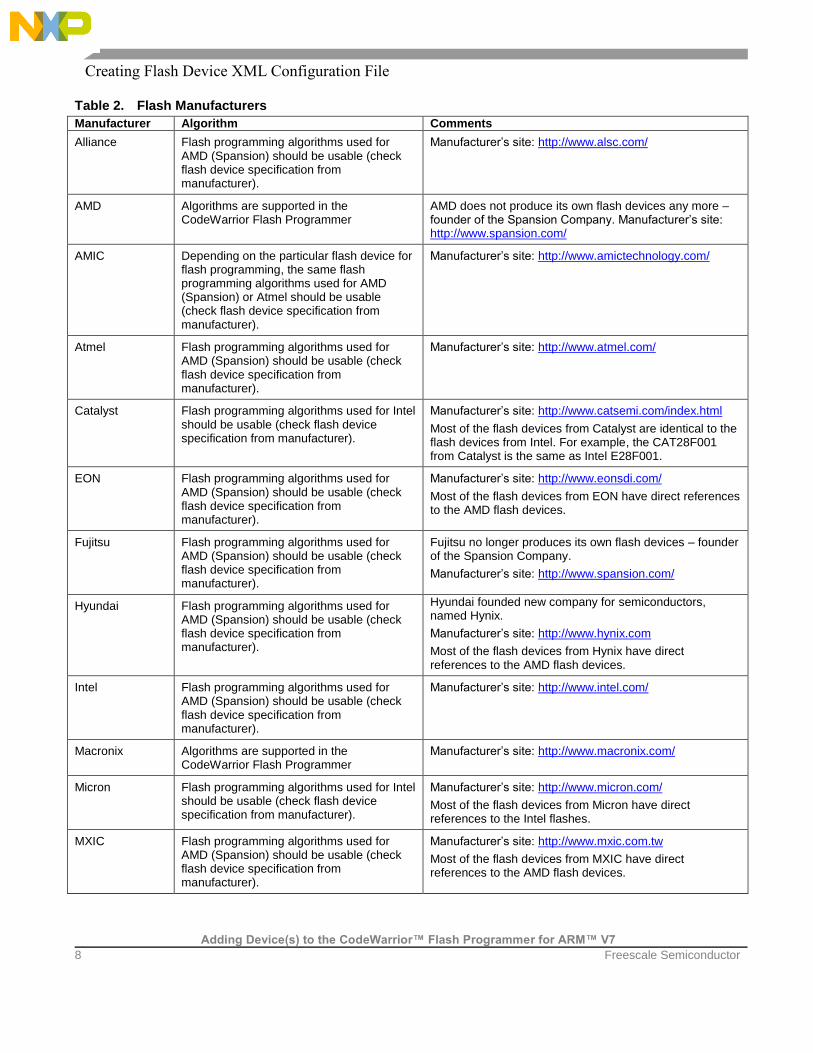
Table 2 lists algorithms, device compatibility, and other information for flash manufacturers.
Creating Flash Device XML Configuration File
Adding Device(s) to the CodeWarrior™ Flash Programmer for ARM™ V7
8 Freescale Semiconductor
Table 2. Flash Manufacturers
Manufacturer Algorithm Comments
Alliance Flash programming algorithms used for AMD (Spansion) should be usable (check flash device specification from manufacturer).
Manufacturer’s site: http://www.alsc.com/
AMD Algorithms are supported in the CodeWarrior Flash Programmer
AMD does not produce its own flash devices any more – founder of the Spansion Company. Manufacturer’s site: http://www.spansion.com/
AMIC Depending on the particular flash device for flash programming, the same flash programming algorithms used for AMD (Spansion) or Atmel should be usable (check flash device specification from manufacturer).
Manufacturer’s site: http://www.amictechnology.com/
Atmel Flash programming algorithms used for AMD (Spansion) should be usable (check flash device specification from manufacturer).
Manufacturer’s site: http://www.atmel.com/
Catalyst Flash programming algorithms used for Intel should be usable (check flash device specification from manufacturer).
Manufacturer’s site: http://www.catsemi.com/index.html
Most of the flash devices from Catalyst are identical to the flash devices from Intel. For example, the CAT28F001 from Catalyst is the same as Intel E28F001.
EON Flash programming algorithms used for AMD (Spansion) should be usable (check flash device specification from manufacturer).
Manufacturer’s site: http://www.eonsdi.com/
Most of the flash devices from EON have direct references to the AMD flash devices.
Fujitsu Flash programming algorithms used for AMD (Spansion) should be usable (check flash device specification from manufacturer).
Fujitsu no longer produces its own flash devices – founder of the Spansion Company.
Manufacturer’s site: http://www.spansion.com/
Hyundai Flash programming algorithms used for AMD (Spansion) should be usable (check flash device specification from manufacturer).
Hyundai founded new company for semiconductors, named Hynix.
Manufacturer’s site: http://www.hynix.com
Most of the flash devices from Hynix have direct references to the AMD flash devices.
Intel Flash programming algorithms used for AMD (Spansion) should be usable (check flash device specification from manufacturer).
Manufacturer’s site: http://www.intel.com/
Macronix Algorithms are supported in the CodeWarrior Flash Programmer
Manufacturer’s site: http://www.macronix.com/
Micron Flash programming algorithms used for Intel should be usable (check flash device specification from manufacturer).
Manufacturer’s site: http://www.micron.com/
Most of the flash devices from Micron have direct references to the Intel flashes.
MXIC Flash programming algorithms used for AMD (Spansion) should be usable (check flash device specification from manufacturer).
Manufacturer’s site: http://www.mxic.com.tw
Most of the flash devices from MXIC have direct references to the AMD flash devices.

Creating Flash Device XML Configuration File
Adding Device(s) to the CodeWarrior™ Flash Programmer for ARM™ V7
Freescale Semiconductor 9
Manufacturer Algorithm Comments
Samsung Flash programming algorithms are not supported in the CodeWarrior Flash Programmer.
Manufacturer’s site: www.samsung.com/products/semiconductor/OneNAND
Samsung uses its own algorithm for flash programming, not compatible with other vendors.
Sharp Flash programming algorithms used for Intel should be usable (check flash device specification from manufacturer).
Manufacturer’s site: http://www.sharpsma.com
Spansion Algorithms are already supported in the CodeWarrior Flash Programmer.
Manufacturer’s site: http://www.spansion.com/
SST Depending on the particular flash device used for flash programming, the same flash programming algorithms used for AMD (Spansion), AMD should be usable (check flash device specification from manufacturer).
Produces flash devices compatible with Intel, AMD, and Atmel
Manufacturer’s site: http://www.sst.com/about/
ST Flash programming algorithms used for AMD (Spansion) should be usable (check flash device specification from manufacturer).
Manufacturer’s site: http://www.st.com
Toshiba Flash programming algorithms used for Intel should be usable (check flash device specification from manufacturer).
Manufacturer’s site: http://www.semicon.toshiba.co.jp/eng
White Flash programming algorithms used for AMD (Spansion) should be usable (check flash device specification from manufacturer).
Manufacturer’s site: http://www.wedc.com/
Winbond Flash programming algorithms used for AMD (Spansion) should be usable (check flash device specification from manufacturer).
Manufacturer’s site: http://www.winbond-usa.com/mambo/content/
view/289/553/
4.8. Set Verify Type
The verify operation can be done in two ways: on target and on host. If the verify operation is done on
host, the CodeWarrior software reads data from the target and compares it to the one that was recently
programmed. When the operation is done on target, a flash utility and the data to be verified will be
downloaded.
The format is:
<ontargetverify>TRUE or FALSE</ontargetverify>
4.9. Set Verify after Program option
The Verify after Program option is intended to improve the user experience by reducing the time
needed to program and verify a file on the target board. Currently, the program and verify operations are
performed separately. The file is downloaded to the target for each operation (except NOR, where the

Creating Flash Device XML Configuration File
Adding Device(s) to the CodeWarrior™ Flash Programmer for ARM™ V7
10 Freescale Semiconductor
verify operation is made on the host itself), which has a significant impact on the run time. To combine
both the operations, perform the following steps:
1. Add <verifyafterprogram> tag in all the XML Flash Programmable devices.
2. The Verify after program checkbox appears in the Add Program/Verify Action dialog. It
indicates that a verify operation is combined with the program operation for the file. Ensure to
select Verify after program checkbox.
Figure 1. Add Program/Verify Action dialog
3. Click Done to close the Add Program/Verify Action dialog.
The new operation gets listed under the Operation list of the target task window.
Figure 2. Target Task Window – Flash Programmer Actions Panel
4.10. Select Flash Utility
The flash algorithms are used for erase and program operations. Blank check, checksum, and sometimes
verify operations (depending on the value of <ontargetverify>) are done with another program,
called flash utility. If the flash device is memory mapped (NOR type), then we can use the default
FlashUtility.elf. This provides support only for blank check and checksum. The verify operation
must be done on host, so <ontargetverify> should be set to FALSE. If we have a NAND or QSPI
device, then a special utility must be written. The format is:
<utility>FlashUtilityForVariant</utility>
Creating Flash Device XML Configuration File
Adding Device(s) to the CodeWarrior™ Flash Programmer for ARM™ V7
Freescale Semiconductor 11
4.11. Add Flash Device in Database
All flash devices are kept in a common database. When a flash device is added from the flash
programmer user interface, it reads the database and displays all devices found. To ensure that the
devices appear correctly, perform these steps:
1. Add the file in database
2. Change the manifest that specifies which devices exist
3. The device configuration file must be copied in
{CodeWarrior}\ARMv7\bin\plugins\support\Products\ProductData\FPDevices.mwpdb\FP. For
this example, assume that the name is NewFlashDevice.xml.
4. Change the manifest file –
{CodeWarrior}\ARMv7\bin\plugins\support\Products\ProductData\FPDevices.mwpdb\product-
manifest.xml.
5. Add a new section in the <device> tag that specifies a new file exists.
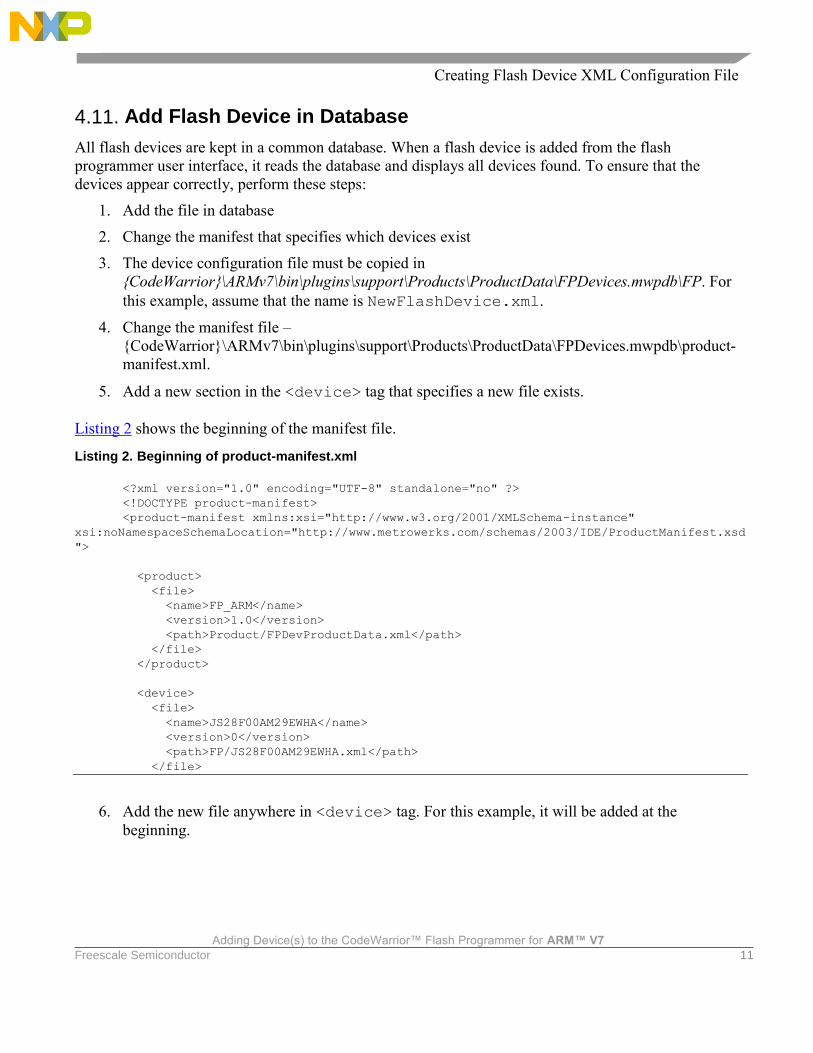
Listing 2 shows the beginning of the manifest file.
Listing 2. Beginning of product-manifest.xml
<?xml version="1.0" encoding="UTF-8" standalone="no" ?>
<!DOCTYPE product-manifest>
<product-manifest xmlns:xsi="http://www.w3.org/2001/XMLSchema-instance"
xsi:noNamespaceSchemaLocation="http://www.metrowerks.com/schemas/2003/IDE/ProductManifest.xsd
">
<product>
<file>
<name>FP_ARM</name>
<version>1.0</version>
<path>Product/FPDevProductData.xml</path>
</file>
</product>
<device>
<file>
<name>JS28F00AM29EWHA</name>
<version>0</version>
<path>FP/JS28F00AM29EWHA.xml</path>
</file>
6. Add the new file anywhere in <device> tag. For this example, it will be added at the
beginning.
Creating New Target Task
Adding Device(s) to the CodeWarrior™ Flash Programmer for ARM™ V7
12 Freescale Semiconductor
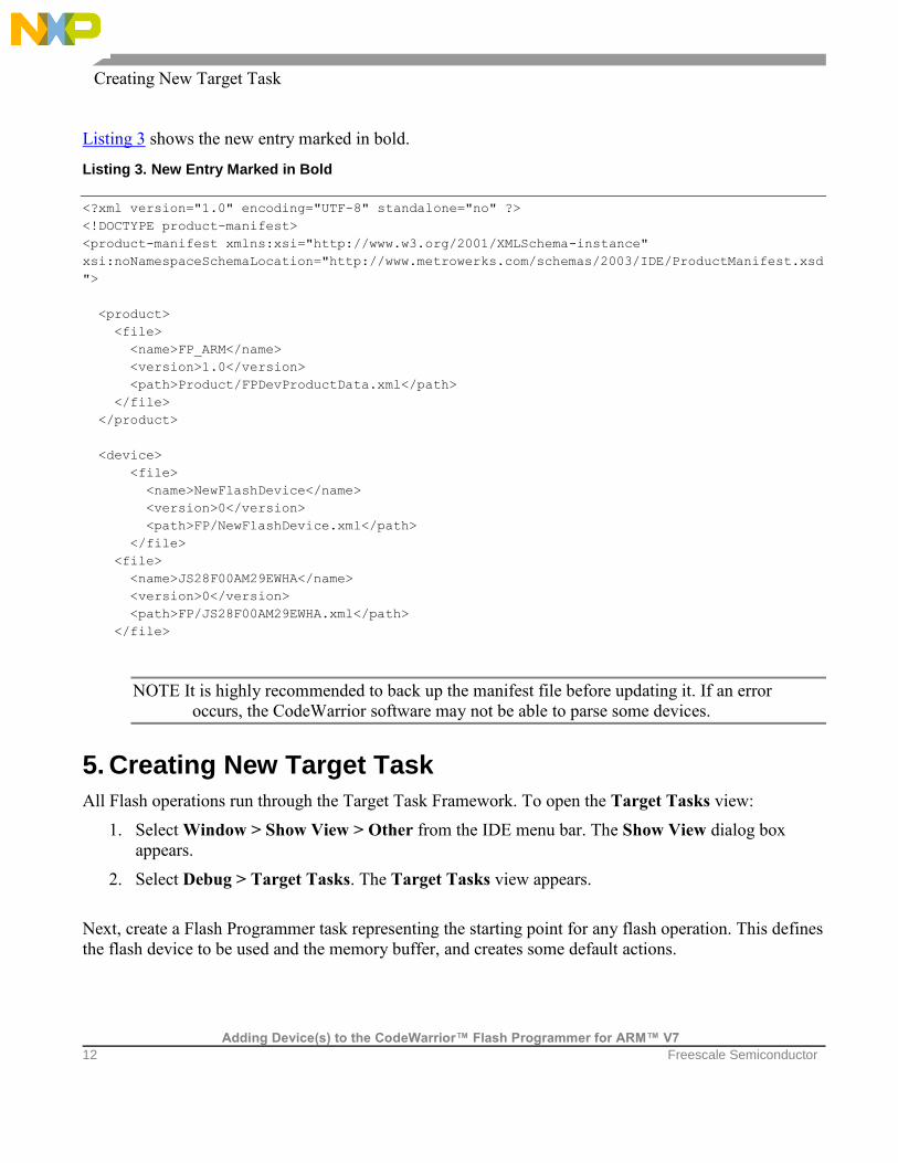
Listing 3 shows the new entry marked in bold.
Listing 3. New Entry Marked in Bold
<?xml version="1.0" encoding="UTF-8" standalone="no" ?>
<!DOCTYPE product-manifest>
<product-manifest xmlns:xsi="http://www.w3.org/2001/XMLSchema-instance"
xsi:noNamespaceSchemaLocation="http://www.metrowerks.com/schemas/2003/IDE/ProductManifest.xsd
">
<product>
<file>
<name>FP_ARM</name>
<version>1.0</version>
<path>Product/FPDevProductData.xml</path>
</file>
</product>
<device>
<file>
<name>NewFlashDevice</name>
<version>0</version>
<path>FP/NewFlashDevice.xml</path>
</file>
<file>
<name>JS28F00AM29EWHA</name>
<version>0</version>
<path>FP/JS28F00AM29EWHA.xml</path>
</file>
NOTE It is highly recommended to back up the manifest file before updating it. If an error
occurs, the CodeWarrior software may not be able to parse some devices.
5. Creating New Target Task
All Flash operations run through the Target Task Framework. To open the Target Tasks view:
1. Select Window > Show View > Other from the IDE menu bar. The Show View dialog box
appears.
2. Select Debug > Target Tasks. The Target Tasks view appears.
Next, create a Flash Programmer task representing the starting point for any flash operation. This defines
the flash device to be used and the memory buffer, and creates some default actions.

Creating New Target Task
Adding Device(s) to the CodeWarrior™ Flash Programmer for ARM™ V7
Freescale Semiconductor 13
5.1. Create New Target Task
To create a new task, perform these steps:
1. Click the Create new target task (“+”) icon on the Target Tasks view toolbar, as shown in
Figure 3.
Figure 3. Create a New Target Task Icon
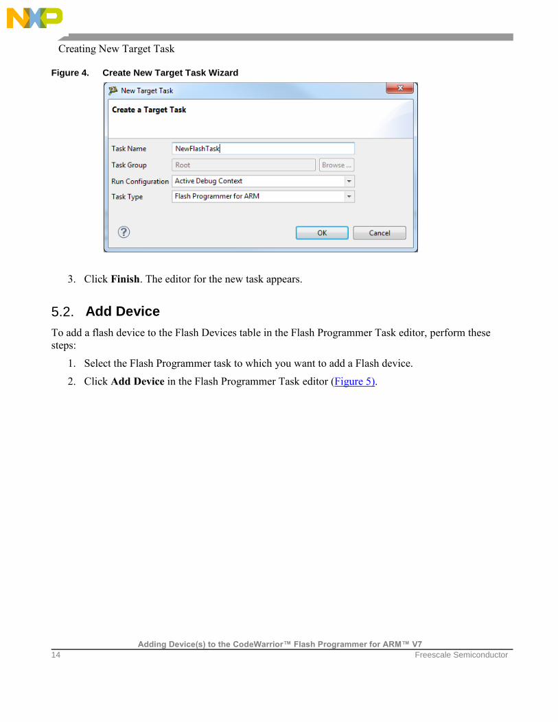
2. The Create New Target Task wizard appears (Figure 4). Specify information in the following
fields:
Task Name: Name of the target task.
Task Group: Group where the task is to be created. If only Root exists this option is disabled.
Run Configuration: Each task must be associated with an existing Launch Configuration or
Active Debug Context. This association is required to be able to make a connection to the
target when doing operations over the flash. Active Debug Context means a connection is
already established and only the task needs to be executed. Use Active Debug Context for
generic tasks or when it is not known which Launch Configurations are available.
Task Type: Type of task created. Select Flash Programmer for ARM.
Creating New Target Task
Adding Device(s) to the CodeWarrior™ Flash Programmer for ARM™ V7
14 Freescale Semiconductor
Figure 4. Create New Target Task Wizard
3. Click Finish. The editor for the new task appears.
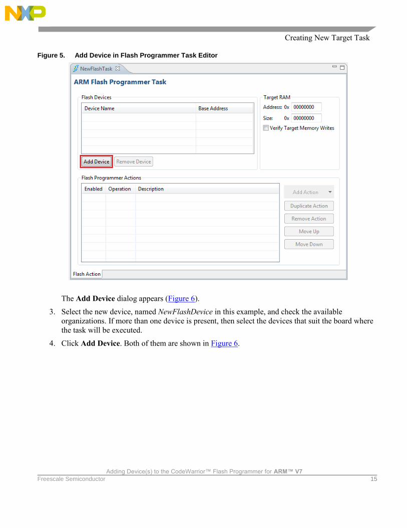
5.2. Add Device
To add a flash device to the Flash Devices table in the Flash Programmer Task editor, perform these
steps:
1. Select the Flash Programmer task to which you want to add a Flash device.
2. Click Add Device in the Flash Programmer Task editor (Figure 5).
Creating New Target Task
Adding Device(s) to the CodeWarrior™ Flash Programmer for ARM™ V7
Freescale Semiconductor 15
Figure 5. Add Device in Flash Programmer Task Editor
The Add Device dialog appears (Figure 6).
3. Select the new device, named NewFlashDevice in this example, and check the available
organizations. If more than one device is present, then select the devices that suit the board where
the task will be executed.
4. Click Add Device. Both of them are shown in Figure 6.

Creating New Target Task
Adding Device(s) to the CodeWarrior™ Flash Programmer for ARM™ V7
16 Freescale Semiconductor
Figure 6. Select Organization and Add Device Button
A pop-up window displays indicating that the device has been added.
5. Click Done. The selected devices are added in the Flash Devices table.
5.3. Populate Default Values
Ensure that the following default values are populated correctly for the flash devices specified in the
target task:
• Base Address: Specifies that the flash device is memory mapped and this address must be defined
in the “Flash Devices” table next to device name.
• Address in Target Ram panel: Specifies the start address of the memory where an algorithm is
downloaded on the target for performing operations on the flash devices.
• Size: Specifies size of the memory buffer for algorithm. The size must be large enough to fit the
algorithm and data that must be programmed. In case the buffer is not big enough, an error will be
displayed when executing the task. The smallest size needed is specified in the Size field.
• Verify Target Writes: Checks if the memory is correctly written. This is done by reading the
memory written after each write command. This allows you to check if the RAM memory is
correctly initialized. By default, it comes unchecked due to the loss of speed that comes with the
overhead of reading memory each time.

Creating New Target Task
Adding Device(s) to the CodeWarrior™ Flash Programmer for ARM™ V7
Freescale Semiconductor 17
All these values must be correct for the board where the flash device is located. Figure 7 shows the
default values for board LS1021 QDS S25FL128S QSPI flash device. All fields that must be filled are
highlighted with red.
Figure 7. Populate Default Values
5.4. Create Default Actions
The various flash programmer actions that can be added to a target task are:
Erasing the whole flash device using Chip Erase
• Blank checking the whole device
• Programming the file from Launch Configuration used to connect to the target
• Verifying the file from Launch Configuration used to connect to the target
• Checksum
• Diagnostics
• Dump flash
• Protect
• Unprotect
Creating New Target Task
Adding Device(s) to the CodeWarrior™ Flash Programmer for ARM™ V7
18 Freescale Semiconductor
All these operations can be selected using Add Action button. In the below steps, this step is not
mentioned to avoid the repetition.
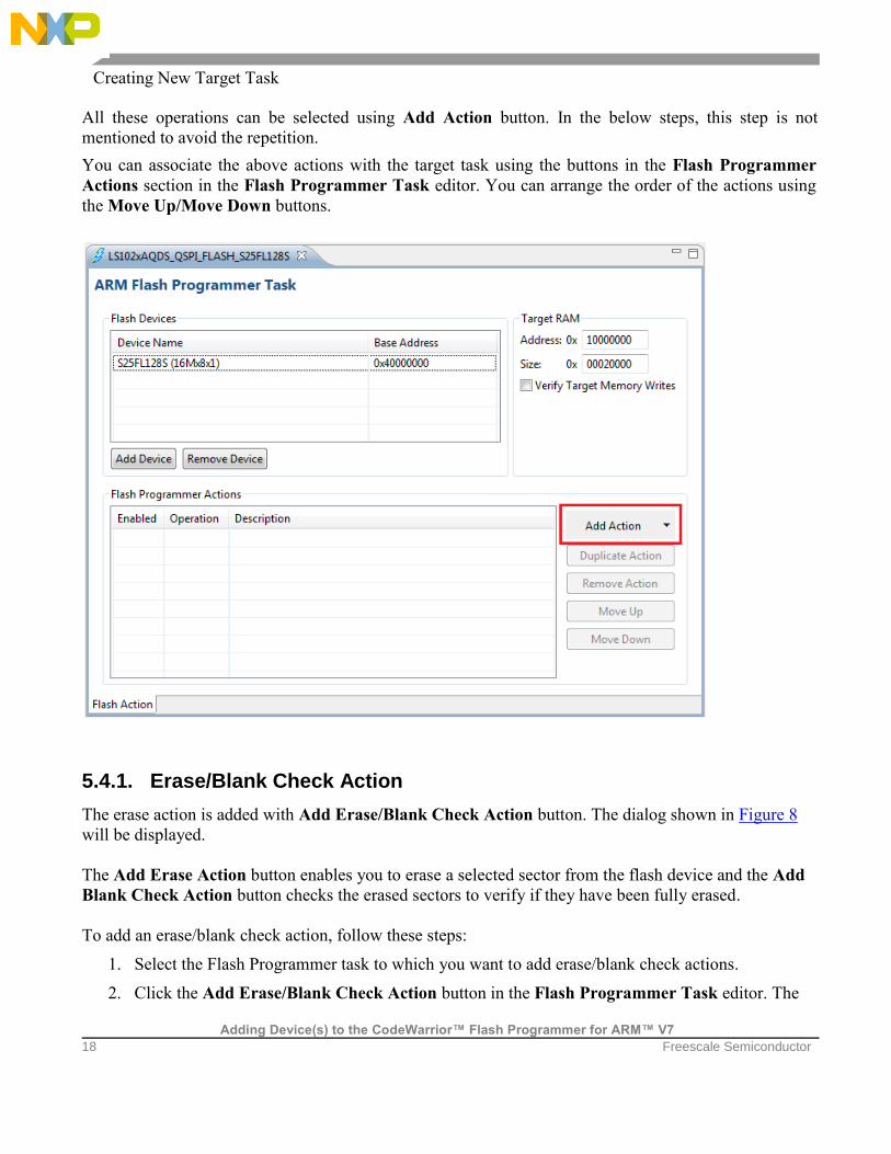
You can associate the above actions with the target task using the buttons in the Flash Programmer
Actions section in the Flash Programmer Task editor. You can arrange the order of the actions using
the Move Up/Move Down buttons.
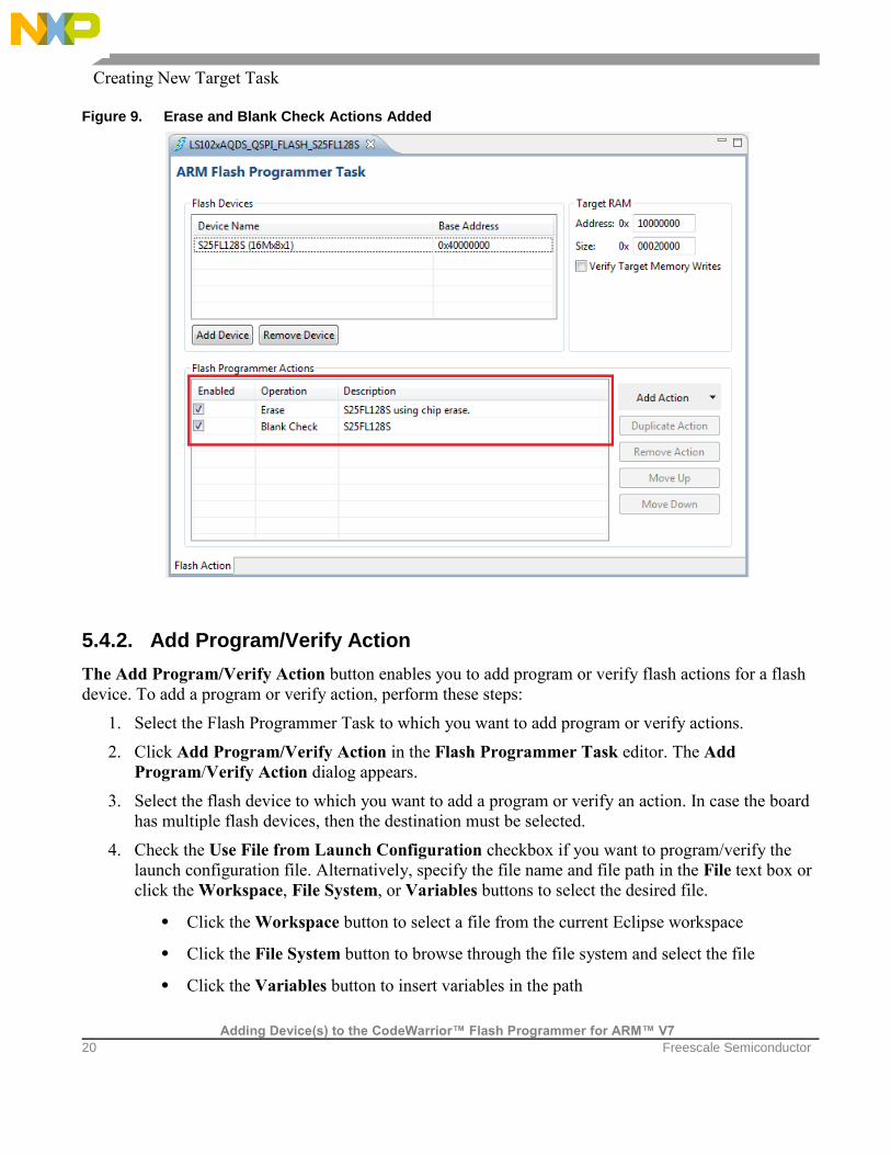
5.4.1. Erase/Blank Check Action
The erase action is added with Add Erase/Blank Check Action button. The dialog shown in Figure 8
will be displayed.
The Add Erase Action button enables you to erase a selected sector from the flash device and the Add
Blank Check Action button checks the erased sectors to verify if they have been fully erased.
To add an erase/blank check action, follow these steps:
1. Select the Flash Programmer task to which you want to add erase/blank check actions.
2. Click the Add Erase/Blank Check Action button in the Flash Programmer Task editor. The

Creating New Target Task
Adding Device(s) to the CodeWarrior™ Flash Programmer for ARM™ V7
Freescale Semiconductor 19
Add Erase /Blank Check Action dialog appears.
3. Select the flash device to which you want to add the erase/blank check action.
4. Select a sector from the Sectors table and click Add Erase Action to add an erase operation on
the selected sector. You can select multiple sectors by holding Ctrl key while selecting the
sectors.
5. Select a sector from the Sectors table and click Add Blank Check Action to add a blank check
operation on the selected sector.
6. Check the Erase All Sectors Using Chip Erase Command check box to erase entire flash. To
erase only a part of the device, leave it unselected and select only some of the sectors. If the size
of the file to be programmed is unknown (for example, for an elf file, where only the necessary
sections are downloaded on the flash), then you can use “Erase sectors before program” option.
Using this option is better than erasing the entire flash, because for NAND flashes, the erase
operation will fail if bad blocks are found. Also, to write something in flash, you need to erase it
first or you will not be able to write the new information.
Figure 8. Add Erase/Blank Check Action Dialog
7. Click Done to close the Add Erase/Blank Check Action dialog. The added erase /blank check
actions appear in the Flash Programmer Actions table (Figure 9).
Creating New Target Task
Adding Device(s) to the CodeWarrior™ Flash Programmer for ARM™ V7
20 Freescale Semiconductor
Figure 9. Erase and Blank Check Actions Added
5.4.2. Add Program/Verify Action
The Add Program/Verify Action button enables you to add program or verify flash actions for a flash
device. To add a program or verify action, perform these steps:
1. Select the Flash Programmer Task to which you want to add program or verify actions.
2. Click Add Program/Verify Action in the Flash Programmer Task editor. The Add
Program/Verify Action dialog appears.
3. Select the flash device to which you want to add a program or verify an action. In case the board
has multiple flash devices, then the destination must be selected.
4. Check the Use File from Launch Configuration checkbox if you want to program/verify the
launch configuration file. Alternatively, specify the file name and file path in the File text box or
click the Workspace, File System, or Variables buttons to select the desired file.
• Click the Workspace button to select a file from the current Eclipse workspace
• Click the File System button to browse through the file system and select the file
• Click the Variables button to insert variables in the path

Creating New Target Task
Adding Device(s) to the CodeWarrior™ Flash Programmer for ARM™ V7
Freescale Semiconductor 21
5. Define how the file should be read by selecting appropriate option from the File Type drop-down
list. The following options are available:
• Auto: The Flash Programmer detects files of type Elf and Srec
• Elf: Elf executable file
• Srec: Motorola .s19 file format
• Binary: The file is read in binary format, no content interpretation is done
6. Select the Restrict to Addresses in this Range checkbox to define a range for flash accesses.
Any program/verify action performed outside this range is ignored. You can specify the range in
the Start and End text boxes, respectively.
7. Select the Apply Address Offset checkbox to apply an offset to the image to be written to the
flash device. You can specify the offset in the Address text box. This value is added to the
(computed) start address of the file.
The start address is zero for binary files or read from the file header. In case you want to use a
binary file and the flash is not mapped to zero, then enable the offset and set the value to the base
address of the flash.
The settings are displayed in Figure 10.
8. Click Add Program Action to add a program action for the flash device.
9. Click Add Verify Action to verify an action for the flash device.
10. Click Done to close the Add Program/Verify Action dialog.
Figure 10. Add Program/Verify Action Dialog
The added program/verify actions appear in the Flash Programmer Actions table as in the Figure 11.
Creating New Target Task
Adding Device(s) to the CodeWarrior™ Flash Programmer for ARM™ V7
22 Freescale Semiconductor
Figure 11. Flash Programmer Actions Table
The task is now complete and should be saved using Ctrl + S or Save icon from toolbar.
5.5. Export Target Task
The final step is to export the task to an .xml file. This allows us to import the task later or from another
machine. To export a task, perform these steps:
1. In the Target Tasks view, select the task you want to export. Right-click the task and select
Export as shown in Figure 12. Alternatively, click the Export icon available on the Target
Tasks view toolbar.

Creating External Flash Algorithm
Adding Device(s) to the CodeWarrior™ Flash Programmer for ARM™ V7
Freescale Semiconductor 23
Figure 12. Export Target Task
The Save As dialog appears.
2. Browse to the desired location, specify the file name, and click the Save button.
The saved task can be imported later using the Import button on the Target Tasks view toolbar.
6. Creating External Flash Algorithm
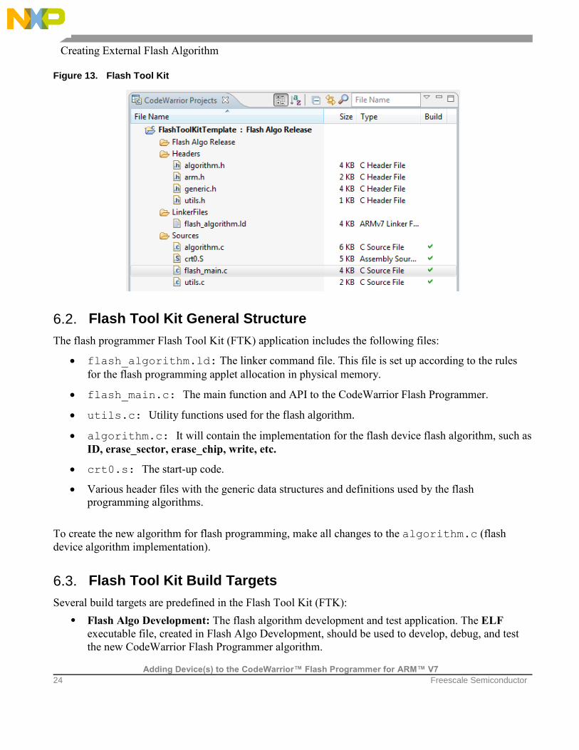
6.1. Flash Tool Kit (FTK) Overview
The Flash Tool Kit helps you develop flash programming algorithms for the CodeWarrior Flash
Programmer, as shown in Figure 13. This section provides important information needed before you
begin creating a flash programming algorithm.
Creating External Flash Algorithm
Adding Device(s) to the CodeWarrior™ Flash Programmer for ARM™ V7
24 Freescale Semiconductor
Figure 13. Flash Tool Kit
6.2. Flash Tool Kit General Structure
The flash programmer Flash Tool Kit (FTK) application includes the following files:
flash_algorithm.ld: The linker command file. This file is set up according to the rules
for the flash programming applet allocation in physical memory.
flash_main.c: The main function and API to the CodeWarrior Flash Programmer.
utils.c: Utility functions used for the flash algorithm.
algorithm.c: It will contain the implementation for the flash device flash algorithm, such as
ID, erase_sector, erase_chip, write, etc.
crt0.s: The start-up code.
Various header files with the generic data structures and definitions used by the flash
programming algorithms.
To create the new algorithm for flash programming, make all changes to the algorithm.c (flash
device algorithm implementation).
6.3. Flash Tool Kit Build Targets
Several build targets are predefined in the Flash Tool Kit (FTK):
• Flash Algo Development: The flash algorithm development and test application. The ELF
executable file, created in Flash Algo Development, should be used to develop, debug, and test
the new CodeWarrior Flash Programmer algorithm.

Creating External Flash Algorithm
Adding Device(s) to the CodeWarrior™ Flash Programmer for ARM™ V7
Freescale Semiconductor 25
• Flash Algo Release: To create flash algorithm applet, the CodeWarrior Flash Programmer uses the
ELF executable file, created in Flash Algo Release. This build target shares the flash device
algorithm with the Flash Algo Development build target; it differs, however, because it cannot be
debugged or tested (Figure 14).
Figure 14. Flash Tool Kit Targets
6.4. Flash Programmer API
The CodeWarrior Flash Programmer communicates with the flash programming algorithm applet
through different commands:
• get ID
• erase sector
• erase chip
• program
• verify
• dump
• protect
• unprotect
• protect sector
• unprotect sector
The CodeWarrior Flash Programmer uses an exchange zone in target memory to communicate with the
flash applet. The Flash Programmer Target Configuration specifies the Target Memory Buffer; the
exchange zone is at the start of this buffer, as shown in Figure 15.

Creating External Flash Algorithm
Adding Device(s) to the CodeWarrior™ Flash Programmer for ARM™ V7
26 Freescale Semiconductor
Figure 15. Target Configuration Buffer Memory Area Start Address
Parameter_block_t Structure
For the detailed description of the Parameter_block_t structure, see Listing 4.
Listing 4. Parameter_block_t structure details
typedef struct pb
{
/*
* What function to perform.
*/
unsigned long function;
/*
* Where are we going to operate.
*/
pointer_t base_addr;
/*
* Number of items.
*/
unsigned long num_items;
/*
* Result of the operation that was executed.
*/
retval_t result_status;
Creating External Flash Algorithm
Adding Device(s) to the CodeWarrior™ Flash Programmer for ARM™ V7
Freescale Semiconductor 27
/*
* Items to be used by the algorithm (data to be written, address of the sectors for
erase / blankcheck)
*/
pointer_t items;
/*
* Used internally only.
*/
unsigned long is_timebase_enabled;
/*
* Padding.
*/
unsigned long padding[3];
/*
* Base address for memory mapped registers.
*/
unsigned long ccsrbar;
/*
* Core Type - used for handle between different processor FP controller structs.
*/
unsigned long core_type;
/*
* Controller offset.
*/
unsigned long controller_offset;
/*
* Controller type.
*/
unsigned long controller_type;
/*
* Padding.
*/
unsigned long padding1[37];
/*
* Number of additional parameters sent by FP Plugin.
*/
unsigned long additionalParameterNum;
/*
* First additional parameter
*/
unsigned long additionalParameterStart;
/*
* Padding for other additional parameters.
*/
unsigned long padding2[7];
} parameter_block_t;
Creating External Flash Algorithm
Adding Device(s) to the CodeWarrior™ Flash Programmer for ARM™ V7
28 Freescale Semiconductor
Listing 4 definitions:
• function: Command to be executed from the CodeWarrior Flash Programmer.
• base_addr: Start address of the flash memory.
• num_items: Number of items to be transferred from the CodeWarrior Flash Programmer to the
flash programming applet.
• result_status: Status of the command; through this field, the flash programming applet
notifies the CodeWarrior Flash Programmer about the status of the command being executed.
Some values for result_status are defined in generic.h; however, the user can define
more, if needed.
• items: Start address of the data to be transferred from the CodeWarrior Flash Programmer to the
flash programming applet.
• is_timebase_enabled: A time-out mechanism can be implemented in the algorithm if
timebase is enabled.
• padding[3]: Used only for internal purposes.
• ccsrbar: Base address for memory mapped registers.
• core_type: Used for handling different processor FP controller structures.
• controller_offset: controller offset address
• controller_type: Controller type – not used for LS1 algorithms.
• padding1: Used only for internal purposes.
• additionalParamenterNum: Number of additional parameters sent by FP plugin.
• additionalParamterStart: Start address for additional parameters.
• padding2: Padding for additional parameters.
NOTE items and base_addr are of type pointer_t, which is a union that can
accommodate different types (such as char*, short*). This arrangement makes the
algorithm scalable, so it can be used for 8-bit, 16-bit, or 32-bit flash.
6.5. Create New Flash Programming Algorithm
This section provides you step-by-step instructions on how to use the Flash Tool Kit to create a new
CodeWarrior Flash Programmer flash programming algorithm for a flash device, which is not integrally
supported by the CodeWarrior software. The steps are given below:
1. Store original versions of the Flash Tool Kit files from the CodeWarrior delivery to some
directory on your machine.
2. Copy FlashToolKitTemplate folder from {CodeWarrior\ARMv7\ARM_Support\
Creating External Flash Algorithm
Adding Device(s) to the CodeWarrior™ Flash Programmer for ARM™ V7
Freescale Semiconductor 29
FlashToolKit\FlashToolKitTemplate to a different directory, where
CodeWarriorInstallDir specifies the location where the CodeWarrior software is installed.
3. Import Flash Tool Kit Template project:
Select File Import. The Import dialog appears.
Select General Existing Projects into Workspace and click Next. The Import
Projects page appears.
Click Browse to select the parent folder where you have copied the
FlashToolKitTemplate folder.
The Projects list will show all available projects in the FlashToolKitTemplate
folder. If you see projects other than FlashToolKitTemplate, then deselect all other
projects and click Finish.
Ensure the Flash Algo Development build target is selected.
4. Select Run Debug Configuration. The Debug Configuration dialog appears.
5. Expand the CodeWarrior Download tree node and select the desired launch configuration. If
one is not available, create one for your target processor.
6. Specify required target processor, target initialization and memory configuration files for the
connected hardware.
For supported Freescale Evaluation Boards, you can use the debugger configuration files (*.tcl),
and the debugger memory files (*.mem) available with the CodeWarrior Development Studio: {CodeWarrior}\ARMv7\ARM_Support\Initialization_Files
NOTE In case of custom hardware design, the debugger configuration file and the memory
mapping file must be written. Also, the memory initialization file for the flash device
should be checked before trying to create the new flash programming algorithm.
7. Modify the algorithm.c file:
The flash algorithm functionality file, algorithm.c, should be modified and filled with the
correct programming commands, as recommended by the flash device manufacturer.
8. Modify ID function in the algorithm.c file. It is mandatory to implement this function. The
CodeWarrior Flash Programmer uses the getting chip ID command right after the flash algorithm
is loaded to the memory buffer to check if the applet runs.
9. There is a corresponding function inside algorithm.c for every possible flash operation.
NOTE See the flash device manufacturer for the flash device memory organization. See
hardware description for the flash device addressing.
10. Compile Flash Algo Development target:
Creating External Flash Algorithm
Adding Device(s) to the CodeWarrior™ Flash Programmer for ARM™ V7
30 Freescale Semiconductor
During new algorithm creation and testing, use the Flash Algo Development build target of the
Flash Development Kit. Compile the Flash Algo Development target with the algorithm.c
file, which is modified for the flash programming procedures. Compilation will result in creation
of a new flash_alg_debug.elf file.
11. Compile Flash Algo Release target:
When the flash programming algorithm for the new flash device works correctly, compile the
Flash Algo Release target. The output of the Flash Algo Release target —
flash_alg_release.elf — must be copied to the following folder:
{CodeWarior}\ARMv7\bin\plugins\support\Flash_Programmer\ARM_EABI
12. Add a new flash device to the flash programmer:
See Creating Flash Device XML Configuration File section for information on adding a new
flash device.
13. Create a new default target task:
See Creating New Target Task section for information on creating a new default target task.
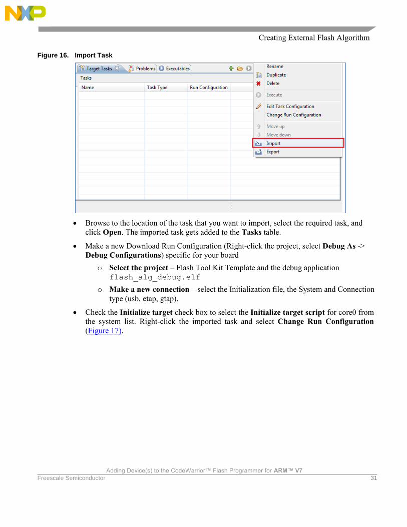
14. Set flash device configuration in flash programmer:
Restart the Eclipse IDE so that the Eclipse IDE can use the new data from the updated
manifest file.
Select Window > Show View > Other… > Debug > Target Tasks from the menu bar to
open the Target Tasks view.
Right-click the Tasks table and select Import from the context menu (Figure 16).
Alternatively, click the icon on the Target Tasks view toolbar to import a task. The
Open dialog box appears.
Creating External Flash Algorithm
Adding Device(s) to the CodeWarrior™ Flash Programmer for ARM™ V7
Freescale Semiconductor 31
Figure 16. Import Task
Browse to the location of the task that you want to import, select the required task, and
click Open. The imported task gets added to the Tasks table.
Make a new Download Run Configuration (Right-click the project, select Debug As ->
Debug Configurations) specific for your board
o Select the project – Flash Tool Kit Template and the debug application
flash_alg_debug.elf
o Make a new connection – select the Initialization file, the System and Connection
type (usb, etap, gtap).
Check the Initialize target check box to select the Initialize target script for core0 from
the system list. Right-click the imported task and select Change Run Configuration
(Figure 17).
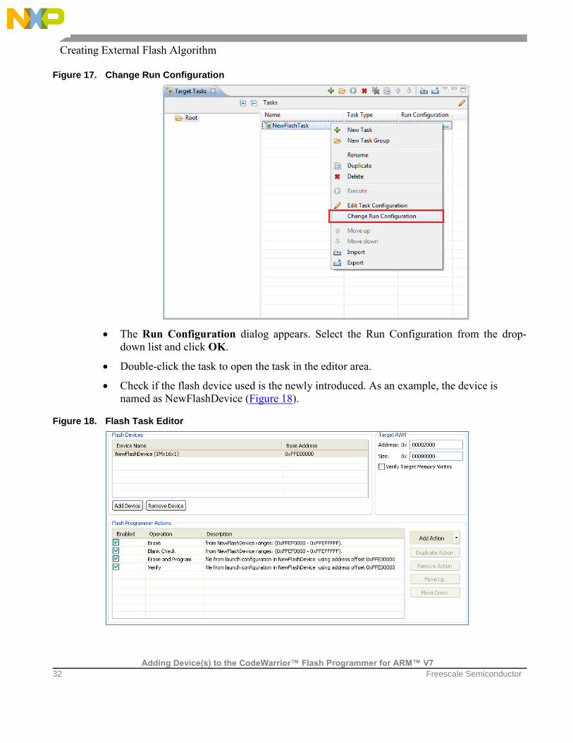
Creating External Flash Algorithm
Adding Device(s) to the CodeWarrior™ Flash Programmer for ARM™ V7
32 Freescale Semiconductor
Figure 17. Change Run Configuration
The Run Configuration dialog appears. Select the Run Configuration from the drop-
down list and click OK.
Double-click the task to open the task in the editor area.
Check if the flash device used is the newly introduced. As an example, the device is
named as NewFlashDevice (Figure 18).
Figure 18. Flash Task Editor

Creating External Flash Algorithm
Adding Device(s) to the CodeWarrior™ Flash Programmer for ARM™ V7
Freescale Semiconductor 33
15. Erase and blank check the device:
Select only Erase and Blank Check actions (Figure 19).
Figure 19. Erase and Blank Check actions selected
Save the task by pressing Ctrl + S or choosing Save button from toolbar.
Select Window > Preferences from the IDE menu bar. The Preferences dialog box
appears.
Select C/C++ > Debug > CodeWarrior Debugger and check the Show verbose output in
Target Tasks check box in the CodeWarrior Debugger panel.
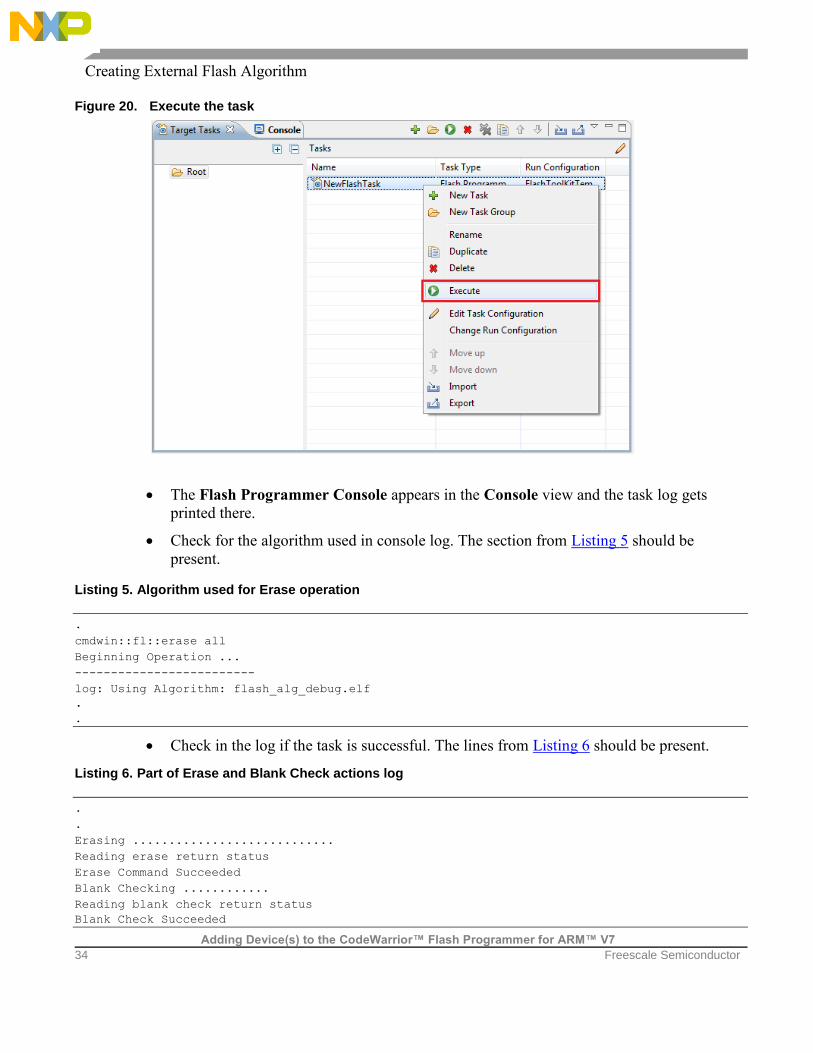
Right-click the task and select Execute (Figure 20).
Creating External Flash Algorithm
Adding Device(s) to the CodeWarrior™ Flash Programmer for ARM™ V7
34 Freescale Semiconductor
Figure 20. Execute the task
The Flash Programmer Console appears in the Console view and the task log gets
printed there.
Check for the algorithm used in console log. The section from Listing 5 should be
present.
Listing 5. Algorithm used for Erase operation
.
cmdwin::fl::erase all
Beginning Operation ...
-------------------------
log: Using Algorithm: flash_alg_debug.elf
.
.
Check in the log if the task is successful. The lines from Listing 6 should be present.
Listing 6. Part of Erase and Blank Check actions log
.
.
Erasing ............................
Reading erase return status
Erase Command Succeeded
Blank Checking ............
Reading blank check return status
Blank Check Succeeded
Creating External Flash Algorithm
Adding Device(s) to the CodeWarrior™ Flash Programmer for ARM™ V7
Freescale Semiconductor 35
NOTE: In case the flash device cannot be erased, check if you are using the correct target task,
and if the hardware connection is set up correctly.
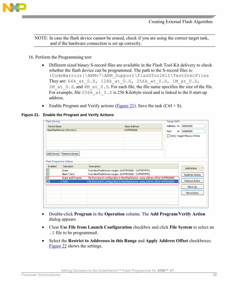
16. Perform the Programming test:
Different sized binary S-record files are available in the Flash Tool Kit delivery to check
whether the flash device can be programmed. The path to the S-record files is: {CodeWarrior}\ARMv7\ARM_Support\FlashToolKit\TestSrecFiles
They are: 64k_at_0.S, 128k_at_0.S, 256k_at_0.S, 1M_at_0.S,
2M_at_0.S, and 4M_at_0.S. For each file, the file name specifies the size of the file.
For example, file 256k_at_0.S is 256 Kilobyte sized and is linked to the 0 start-up
address.
Enable Program and Verify actions (Figure 21). Save the task (Ctrl + S).
Figure 21. Enable the Program and Verify Actions
Double-click Program in the Operation column. The Add Program/Verify Action
dialog appears.
Clear Use File from Launch Configuration checkbox and click File System to select an
.S file to be programmed.
Select the Restrict to Addresses in this Range and Apply Address Offset checkboxes.
Figure 22 shows the settings.

Creating External Flash Algorithm
Adding Device(s) to the CodeWarrior™ Flash Programmer for ARM™ V7
36 Freescale Semiconductor
Figure 22. Add Program/Verify Action Dialog
Figure 22 definitions:
o Restrict to Addresses in this Range: Specifies the address range of the flash device
o Apply Address Offset: Specifies the start address, where the test data is
programmed in the flash; it should be the flash device start address.
Click Update Program Action.
Repeat steps d), e), and f) for Verify action.
Execute the task.
Check the Console view for the algorithms used in execution of the task, as shown in
Listing 7.
Listing 7. Programming test log
Downloading 0x00002800 bytes to be programmed at 0xFFEFD800
Writing Program Function Code
Writing the Address
Writing the Size
Writing the address of the buffer
Clearing the status
Setting up Registers
Commanding target to run
Programming ...
Reading program return status
Program Command Succeeded
log: Programmed total of 0x00100000 bytes
log:
log: Program Command Succeeded
.
.
Uploading 0x00010000 bytes starting from address 0xFFEF0000
log: Uploading 0x00010000 bytes starting from address 0xFFEF0000
log: Verified total of 0x00100000 bytes
Creating New Flash Utility
Adding Device(s) to the CodeWarrior™ Flash Programmer for ARM™ V7
Freescale Semiconductor 37
log:
Verify Command Succeeded
If all program/verify actions pass correctly, you have completed creation of a new flash
programming algorithm. The new flash device can be programmed with the CodeWarrior
Flash Programmer without any limitation.
7. Creating New Flash Utility
Some flash devices, such as NAND and SPI are not memory mapped. The memory cannot be read
directly; therefore, a special utility is needed for blank check and checksum operations. This is very
similar to a flash algorithm. It receives the commands through a data structure and passes back the
results through the same structure.
7.1. Flash Utility Template Overview
The Flash Utility Template described in this document also helps you develop flash utilities for the
CodeWarrior Flash Programmer, as shown in Figure 23. This section provides important information
needed before you begin creating a flash utility.
Creating New Flash Utility
Adding Device(s) to the CodeWarrior™ Flash Programmer for ARM™ V7
38 Freescale Semiconductor
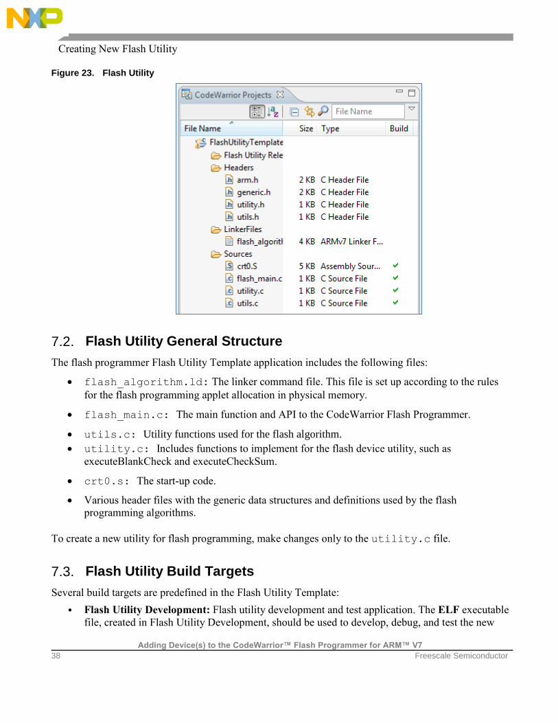
Figure 23. Flash Utility
7.2. Flash Utility General Structure
The flash programmer Flash Utility Template application includes the following files:
flash_algorithm.ld: The linker command file. This file is set up according to the rules
for the flash programming applet allocation in physical memory.
flash_main.c: The main function and API to the CodeWarrior Flash Programmer.
utils.c: Utility functions used for the flash algorithm.
utility.c: Includes functions to implement for the flash device utility, such as
executeBlankCheck and executeCheckSum.
crt0.s: The start-up code.
Various header files with the generic data structures and definitions used by the flash
programming algorithms.
To create a new utility for flash programming, make changes only to the utility.c file.
7.3. Flash Utility Build Targets
Several build targets are predefined in the Flash Utility Template:
• Flash Utility Development: Flash utility development and test application. The ELF executable
file, created in Flash Utility Development, should be used to develop, debug, and test the new

Creating New Flash Utility
Adding Device(s) to the CodeWarrior™ Flash Programmer for ARM™ V7
Freescale Semiconductor 39
CodeWarrior Flash Programmer utility.
• Flash Utility Release: To create flash utility applet, the CodeWarrior Flash Programmer uses the
ELF executable file, created in Flash Utility Release. This build target shares the flash device
utility with the Flash Utility Development build target; it differs, however, because it cannot be
debugged or tested (Figure 24).
Figure 24. Flash Utility Targets
7.4. Flash Utility API
The CodeWarrior Flash Programmer communicates with the flash utility applet through two different
commands:
• Blank Check
• Checksum
The same memory zone defined for Flash Device Algorithm, the parameterBlockType structure, is
used by the utility.
On the flash utility side, the commands from the CodeWarrior Flash Programmer go through the
parameterBlockType structure, and are mapped in the memory, from the beginning of the memory
buffer.
All commands from the CodeWarrior Flash Programmer are already encoded in utility_main.c
file. This file can be used for the new flash programming algorithm without any modification. After
loading the utility applet to the target board, the CodeWarrior Flash Programmer writes all parameters
right in the data structure located at the beginning of the memory buffer.
Creating New Flash Utility
Adding Device(s) to the CodeWarrior™ Flash Programmer for ARM™ V7
40 Freescale Semiconductor
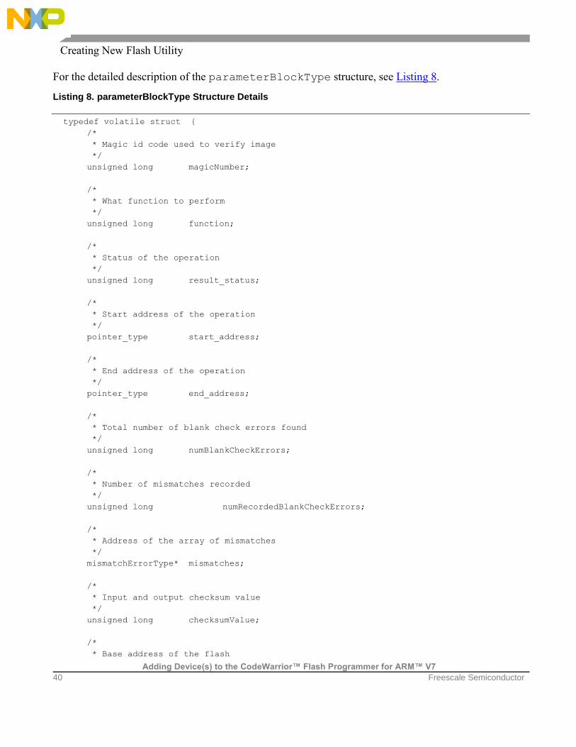
For the detailed description of the parameterBlockType structure, see Listing 8.
Listing 8. parameterBlockType Structure Details
typedef volatile struct {
/*
* Magic id code used to verify image
*/
unsigned long magicNumber;
/*
* What function to perform
*/
unsigned long function;
/*
* Status of the operation
*/
unsigned long result_status;
/*
* Start address of the operation
*/
pointer_type start_address;
/*
* End address of the operation
*/
pointer_type end_address;
/*
* Total number of blank check errors found
*/
unsigned long numBlankCheckErrors;
/*
* Number of mismatches recorded
*/
unsigned long numRecordedBlankCheckErrors;
/*
* Address of the array of mismatches
*/
mismatchErrorType* mismatches;
/*
* Input and output checksum value
*/
unsigned long checksumValue;
/*
* Base address of the flash
Creating New Flash Utility
Adding Device(s) to the CodeWarrior™ Flash Programmer for ARM™ V7
Freescale Semiconductor 41
*/
unsigned long baseAddress;
/*
* Base address for memory mapped registers
*/
unsigned long ccsrbar;
/*
* Core Type - used for handle between different processor FP controller structs
*/
unsigned long core_type;
/*
* Controller Offset
*/
unsigned long controller_offset;
/*
* Controller Type
*/
unsigned long controller_type;
/*
* Number of additional parameters sent by FP Plugin
*/
unsigned long additionalParameterNum;
/*
* First additional parameter
*/
unsigned long additionalParameterStart;
/*
* Padding for other additional parameters
*/
unsigned long padding[7];
} parameterBlockType;
Listing 8 definitions:
magicNumber: Indicates a number written at the beginning of the flash utility parameter block.
The CodeWarrior Flash Programmer reads the first location from the memory buffer upon
downloading the utility. The expected value is 0xBCC5BCC5.
function: Specifies the command to be executed. It can be blank check or checksum.
result_status: Contains the operation result. It can be success, fail, or unknown command.
start_address: Specifies the start address for the requested command.
end_address: Specifies the end address for the requested command.
Creating New Flash Utility
Adding Device(s) to the CodeWarrior™ Flash Programmer for ARM™ V7
42 Freescale Semiconductor
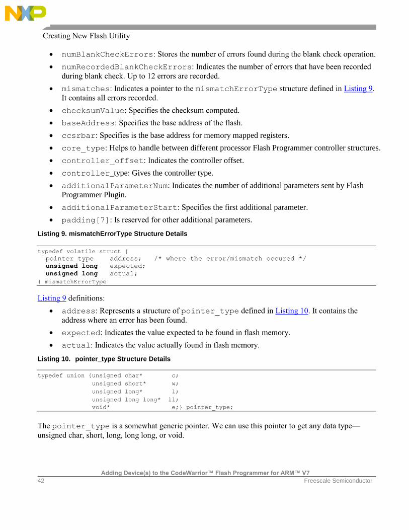
numBlankCheckErrors: Stores the number of errors found during the blank check operation.
numRecordedBlankCheckErrors: Indicates the number of errors that have been recorded
during blank check. Up to 12 errors are recorded.
mismatches: Indicates a pointer to the mismatchErrorType structure defined in Listing 9.
It contains all errors recorded.
checksumValue: Specifies the checksum computed.
baseAddress: Specifies the base address of the flash.
ccsrbar: Specifies is the base address for memory mapped registers.
core_type: Helps to handle between different processor Flash Programmer controller structures.
controller_offset: Indicates the controller offset.
controller_type: Gives the controller type.
additionalParameterNum: Indicates the number of additional parameters sent by Flash
Programmer Plugin.
additionalParameterStart: Specifies the first additional parameter.
padding[7]: Is reserved for other additional parameters.
Listing 9. mismatchErrorType Structure Details
typedef volatile struct {
pointer_type address; /* where the error/mismatch occured */
unsigned long expected;
unsigned long actual;
} mismatchErrorType
Listing 9 definitions:
address: Represents a structure of pointer_type defined in Listing 10. It contains the
address where an error has been found.
expected: Indicates the value expected to be found in flash memory.
actual: Indicates the value actually found in flash memory.
Listing 10. pointer_type Structure Details
typedef union {unsigned char* c;
unsigned short* w;
unsigned long* l;
unsigned long long* ll;
void* e;} pointer_type;
The pointer_type is a somewhat generic pointer. We can use this pointer to get any data type—
unsigned char, short, long, long long, or void.
Creating New Flash Utility
Adding Device(s) to the CodeWarrior™ Flash Programmer for ARM™ V7
Freescale Semiconductor 43
The supported functions are:
BlankCheck
The BlankCheck command is called by the flash programmer to blank check a memory range. For the
BlankCheck command, the CodeWarrior Flash Programmer:
Loads the flash utility on the target board
Sets the BlankCheck command as shown in the function field of Listing 8
Sets the start_address and end_address parameters as shown in the function field of
Listing 8
Runs the flash utility applet
Waits until flash utility stops execution
Checks the status of the command being executed as shown in result_status from Listing 8
Reads the number of errors and records the errors and their location if the status reports an error, as
shown in Listing 8
Checksum
The Checksum command is called by the flash programmer to blank check a memory range. For the
Checksum command, the CodeWarrior Flash Programmer:
Loads the flash utility on the target board
Sets the Checksum command as shown in the function field of Listing 8
Sets the start_address and end_address parameters as shown in the function field of
Listing 8
Runs the flash utility applet
Waits until flash utility stops execution
Checks the status of the command being executed as shown in result_status from Listing 8
Reads the checksum result if status is success, as shown in Listing 8
7.5. Create New Flash Utility
To create a new CodeWarrior Flash Programmer flash utility using the Flash Utility Template, for a
flash device not supported by the CodeWarrior software:
1. Store the original version of Flash Utility Template available in the CodeWarrior delivery to a
different working directory. The location of the FlashUtilityTemplate folder is: {CodeWarrior\ ARMv7\ARM_Support\FlashToolKit\FlashUtilityTemplate
2. Import Flash Utility Template project:
Select FileImport from the IDE menu bar. The Import dialog appears.
Select GeneralExisting Projects into Workspace. Click Next. The Import Projects

Creating New Flash Utility
Adding Device(s) to the CodeWarrior™ Flash Programmer for ARM™ V7
44 Freescale Semiconductor
page appears.
Click Browse to choose the parent folder where you have copied the
FlashUtilityTemplate folder, select the folder, and click OK. The Projects list
gets populated with the projects available in the FlashUtilityTemplate folder.
Clear the check boxes next to the projects that you do not want to import and click
Finish. The imported project is displayed in the CodeWarrior Projects view in the
C/C++ perspective, as shown in Figure 23.
Ensure that the Flash Utility Development build target is selected.
3. Select RunDebug Configurations. The Debug Configurations dialog appears.
4. Expand the CodeWarrior Download tree node and select the desired launch configuration. If
one is not available, create one for your target processor.
5. Specify required target initialization and memory configuration files for the connected hardware
in the Target initialization file and Memory Configuration File text boxes. For supported
Freescale Evaluation Boards, you can use the debugger config files (*.tcl), and the debugger
mem files (*.mem) available with the CodeWarrior Development Studio. Check the folder:
{CodeWarrior}\ ARMv7\ARM_Support\Configuration_Files.
6. Modify executeBlankCheck function from utility_impl.c file. The function must
read the command options, perform the blank check and put the results in parameter block.
7. Modify executeCheckSum function from utility_impl.c file. The function must read
the command options, perform the checksum, and put the results back in parameter block.
8. Compile Flash Utility Development target. While creating and testing a new utility, use the Flash
Utility Development build target of the Flash Utility Template project. Compilation will result in
creation of a new flash_utility_debug.elf file.
9. Flash utility unit testing:
To test a flash utility algorithm, define custom flash device parameters in
utility_main.c. You can select the operation you want to perform and the address
in flash to which the operation will be applied.
Load the FlashUtilityTemplateDebug.elf file and run it on a target board.
Check the tests results.
10. Compile Flash Utility Release target. Copy the resulted file in the following folder: {CodeWarior}\ARMv7\bin\plugins\support\Flash_Programmer\ARM_EABI
11. Use the new Flash Utility in the device description XML file. Run a Flash Programmer with the
new device/utility as described for the flash algorithm in Create New Flash Programming
Algorithm.
Troubleshooting Flash Programmer
Adding Device(s) to the CodeWarrior™ Flash Programmer for ARM™ V7
Freescale Semiconductor 45
8. Troubleshooting Flash Programmer
It is possible that the CodeWarrior™ Flash Programmer does not recognize the flash devices on your
target, or has a problem with erasing or programming. If so, use the troubleshooting techniques in this
topic to ensure that basic reads and writes to flash function correctly. If you still cannot program your
flash devices, contact Technical Support at: http://www.freescale.com/support.
This topic explains how to configure your target flash devices to display their manufacturer and device
ID codes. If the devices can display this information, then basic reads and writes to the devices are
functioning correctly. This means that you are unable to program your flash due to either:
• The flash device configuration file
• The flash-programming algorithm
8.1. Theory
Current flash devices use a common method for preventing unintentional programming. A specific
sequence of write cycles must precede each flash programming write cycle, to enable programming of
one byte (8 bits) or word (16 bits). These preceding write cycles walk through an internal-state machine
that enables the flash for one device-programming write cycle. This write-enabling process is necessary
for each flash address to be programmed.
You can use the same method to configure a flash device to display its manufacturer and device ID
codes:
• The manufacturer ID code is the same for all devices from each manufacturer. Common codes are
0x01 for AMD, 0x1F for Atmel, and 0x89 for Intel.
• Device ID code is unique for each device; each device’s data sheet specifies its ID code.
Reading these ID codes requires successful write and read cycles to each flash device. This indicates that
the flash-programming problems exist in the CodeWarrior Flash Programmer rather than in the target
hardware. Similarly, inability to read these ID codes indicates a low-level problem with reading/writing
target flash. You must resolve such hardware problems for the flash programmer to work.
8.2. Practice
The explanation of this document involves using the CodeWarrior debugger and its Command Line
panel to write to and to read from target flash. Before you begin, you must be running a debug session to
the target.
The process uses the CodeWarrior commands, change, which writes to memory, and display, which
reads from memory. The general formats are:
change p:<address><value><bus-width>
display p:<start_address>..<end_address><bus-width>
Troubleshooting Flash Programmer
Adding Device(s) to the CodeWarrior™ Flash Programmer for ARM™ V7
46 Freescale Semiconductor
where:
• <address>, <start_address>, and <end_address> are address values that comply
with the CodeWarrior default radix, or with an explicitly defined radix.
• <value> is a data value that complies with the CodeWarrior default radix, or with an explicitly
defined radix.
• <bus_width> is 8bit, 16bit, 32bit, or 64bit.
These commands are used to push flash commands to the devices on your target and then to read the
data that the flash presents. All flash devices use a flash-command state machine to process commands,
such as ReadDevice ID, Erase Sector, and Program. See the data sheet for details of the device command
sequences.
This section presents common command sets for reading manufacturer and device IDs. To use any of
these examples, you must change the strings %%% to the high-order starting address of the flash on your
target. For example, if the flash base address is 0xffe00000, your replacement string for %%% is ffe.
The data values in these examples must remain as listed.
To use these command sets:
• Enter each of the change and display commands exactly as listed, except for substituting the
correct high-order address string for %%%.
• Examine the information you obtain from the display command for the ID codes defined in the
data sheet for your flash device.
If the manufacturer of your target flash device is not AMD, Atmel, or Intel, then compare the command
sequences of your devices with the command sequences of the devices manufactured by AMD, Atmel,
and Intel. Most likely, your device uses the command sequence of one of these device manufacturers.
Fujitsu flash devices, for example, use the same commands as AMD devices. Sharp flash devices use the
same commands as Intel devices. And even if your flash device does not use exactly the AMD, Atmel,
or Intel command sequence, the command sequence should be nearly similar. You can, therefore, easily
adapt the command sequences of other device manufacturers.
8.3. Using CodeWarrior Script Files
The CodeWarrior source command reads the contents of a text file as a list of sequential CodeWarrior
commands. Accordingly, you may copy the contents of any listing, below, to a text file with extension
.tcl. Then, use the source command to invoke the script. See examples 1 and 2 for more information.
8.4. Before You Start
Before you can start diagnosing flash problems, gather as much of this information as possible:
• Device manufacturer, such as AMD, Atmel, or Intel

Troubleshooting Flash Programmer
Adding Device(s) to the CodeWarrior™ Flash Programmer for ARM™ V7
Freescale Semiconductor 47
• Device part number
• Number of devices on your target
• Number of data bits (8 or 16) each flash device uses
• Starting flash address on the target
NOTE You can also troubleshoot your flash device without the information listed above.
However, that would increase your efforts. The instructions below are consistent with
you having all this information.
To ensure that your ID-value interrogation does not fail:
1. Writes to flash and reads from flash must occur exactly as the manufacturer defines for reading
out the manufacturer and device ID codes. Ensure that you disable all address-translation and
memory management features.
2. Disable all processor caches. (You must write to/read from the actual flash devices, not a cached
copy of flash.)
3. Check the target schematic, to ensure that each WE# (write-enable) processor signal reaches the
correct WE# pin of each target flash device. The target hardware, the target-processor
configuration, or both, can disable the WE# signal.
4. Check the memory-control registers of the target processor, to ensure that flash accesses are not
read-only.
5. For a 16-bit flash device, determine whether the processor’s least-significant address line is
connected to the flash device. If so, you can rely on the addresses of the flash data sheet. An
example is the AMD AM29LV640D/AM29LV641D data sheet, which specifies this sequence
for reading device and manufacturer ID codes: %%%0555 = AA
%%%02AA = 55
%%%0555 = 90
But many processors do not have the least-significant address line connected to the flash device,
as there is no reason to address individual bytes. If this is the arrangement for your target, you
must compensate by shifting data sheet addresses left by one. This would change the sequence
above to: %%%0AAA = AA
%%%0554 = 55
%%%0AAA = 90
6. Confirm that data bus least significant bit of each flash device connects to the least significant bit
of the processor. The CodeWarrior Flash Programmer does not support reverse wired flash
devices.
Troubleshooting Flash Programmer
Adding Device(s) to the CodeWarrior™ Flash Programmer for ARM™ V7
48 Freescale Semiconductor
8.4.1. AMD Devices
Some AMD devices are dual-mode, supporting either 8 bit or 16 bit modes. To determine the mode,
check the state of the flash BYTE pin: BYTE = 0 means 8 bit mode configuration; BYTE = 1 means 16
bit mode configuration.
From Listing 11 to Listing 19 provides command sequences for AMD flash devices.
8.4.2. Atmel Devices
From Listing 20 to Listing 25 provides command sequences for Atmel flash devices.
8.4.3. Intel Devices
Listing 26 through Listing 31 provides command sequences for Intel flash devices. The status register
read outs of these listings is not required for reading out the ID codes. However, if you enter these
commands correctly, the status register results show an operation successful status or possible chip
errors.
Some Intel devices are dual-mode, supporting either 8 bit or 16 bit modes. To determine the mode,
check the state of the flash BYTE# pin: BYTE# = 0 means 8 bit mode configuration; BYTE# = 1 means
16 bit mode configuration.
8.5. Procedure
Perform these steps:
1. Start a CodeWarrior debugging session for your target.
2. Identify the appropriate command sequence for your device using Table 9.
If your manufacturer is Fujitsu, use the AMD listing for your arrangement.
If your manufacturer is Sharp, use the Intel listing for your arrangement.
Otherwise, find the closest match for your device arrangement, so that you can modify the
command sequence explained in Step 3.
3. Substitute the high order address string with %%% in the code of the selected listing and perform
either of the following:
Enter the listing commands one after another, in the Debugger Shell view, or
Copy the commands, paste them into a .tcl text file, then use a source command in the
Debugger Shell view to invoke the new script.
4. In the output of the display command, look for the ID codes of your flash device. The device’s
data sheet specifies these code values.
If the output includes the ID codes, you have confirmed that flash device basic reads and
writes function properly. This means that any programming problem lies with the
CodeWarrior software, so you should report the matter to Freescale Technical Support:

Troubleshooting Flash Programmer
Adding Device(s) to the CodeWarrior™ Flash Programmer for ARM™ V7
Freescale Semiconductor 49
www.freescale.com/support.
If the output does not include the ID codes, you have confirmed a low-level problem with
reading from or writing to your flash devices. You must solve this problem locally for the
CodeWarrior Flash Programmer to work.
Two examples follow the command sequence listings.
8.6. Command Sequence Listings
Table 9 lists various flash device arrangements and the corresponding command sequences.
Table 3. Flash Device Command Sequences
Manufacturer Devices See
AMD
One 8-bit device Listing 11
One 8-bit/16-bit device, in 8-bit mode Listing 12
Two 8-bit devices Listing 13
Two 8-bit/16-bit devices, in 8-bit mode Listing 14
Four 8-bit devices Listing 15
Four 8-bit/16-bit devices, in 8-bit mode Listing 16
One 16-bit device Listing 17
Two 16-bit devices Listing 18
Four 16-bit devices Listing 19
Atmel
One 8-bit device Listing 20
Two 8-bit devices Listing 21
Four 8bit devices Listing 22
One 16-bit device Listing 23
Two 16-bit devices Listing 24
Four 16-bit devices Listing 25
Intel
One 8-bit device Listing 26
Two 8-bit devices Listing 27
Four 8-bit devices Listing 28
One 16-bit device Listing 29
Two 16-bit devices Listing 30
Four 16-bit devices Listing 31

Troubleshooting Flash Programmer
Adding Device(s) to the CodeWarrior™ Flash Programmer for ARM™ V7
50 Freescale Semiconductor
Listing 11. AMD: One 8-bit Device
# Set device to Read state
change p:%%%00000 f0 8bit
# Get Mfg and Device ID values
change p:%%%00555 aa 8bit
change p:%%%002aa 55 8bit
change p:%%%00555 90 8bit
# Display Mfg ID value at offset
0# Display Dev ID value at offset 1
display p:%%%00000..%%%00002 8bit
# Reset device to Read state
change p:%%%00000 f0 8bit
Listing 12. AMD: One 8-bit/16-bit Device, in 8-bit Mode
# Set device to Read state
change p:%%%00000 f0 8bit
# Get Mfg and Device ID values
change p:%%%00aaa aa 8bit
change p:%%%00555 55 8bit
change p:%%%00aaa 90 8bit
# Display Mfg ID value at offset 0
# Display Dev ID value at offset 1
display p:%%%00000..%%%00002 8bit
# Reset device to Read state
change p:%%%00000 f0 8bit
Listing 13. AMD: Two 8-bit Devices
# Set devices to Read state
change p:%%%00000 f0f0 16bit
# Get Mfg and Device ID values
change p:%%%00aaa aaaa 16bit
change p:%%%00554 5555 16bit
change p:%%%00aaa 9090 16bit
# Display Mfg ID values at offsets 0, 1
# Display Dev ID values at offsets 2, 3
display p:%%%00000..%%%00004 8bit
# Reset devices to Read state
change p:%%%00000 f0f0 16bit

Troubleshooting Flash Programmer
Adding Device(s) to the CodeWarrior™ Flash Programmer for ARM™ V7
Freescale Semiconductor 51
Listing 14. AMD: Two 8-bit/16-bit Devices, in 8-bit Mode
# Set devices to Read state
change p:%%%00000 f0f0 16bit
# Get Mfg and Device ID values
change p:%%%001554 aaaa 16bit
change p:%%%00aa8 5555 16bit
change p:%%%01554 9090 16bit
# Display Mfg ID values at offsets 0, 1
# Display Dev ID values at offsets 2, 3
display p:%%%00000..%%%00004 8bit
# Reset devices to Read state
change p:%%%00000 f0f0 16bit
Listing 15. AMD: Four 8-bit Devices
# Set devices to Read state
change p:%%%00000 f0f0f0f0 32bit
# Get Mfg and Device ID values
change p:%%%01554 aaaaaaaa 32bit
change p:%%%00aa8 55555555 32bit
change p:%%%01554 90909090 32bit
# Display Mfg ID values at offsets 0, 1, 2, 3
# Display Dev ID values at offsets 4, 5, 6, 7
display p:%%%00000..%%%00008 8bit
# Reset devices to Read state
change p:%%%00000 f0f0f0f0 32bit
Listing 16. AMD: Four 8-bit/16-bit Devices, in 8-bit Mode
# Set devices to Read state
change p:%%%00000 f0f0f0f0 32bit
# Get Mfg and Device ID values
change p:%%%02aa8 aaaaaaaa 32bit
change p:%%%01550 55555555 32bit
change p:%%%02aa8 90909090 32bit
# Display Mfg ID values at offsets 0, 1, 2, 3
# Display Dev ID values at offsets 4, 5, 6, 7
display p:%%%00000..%%%00008 8bit
# Reset devices to Read state
change p:%%%00000 f0f0f0f0 32bit
Listing 17. AMD: One 16-bit Device
# Set device to Read state
change p:%%%00000 f0f0 16bit
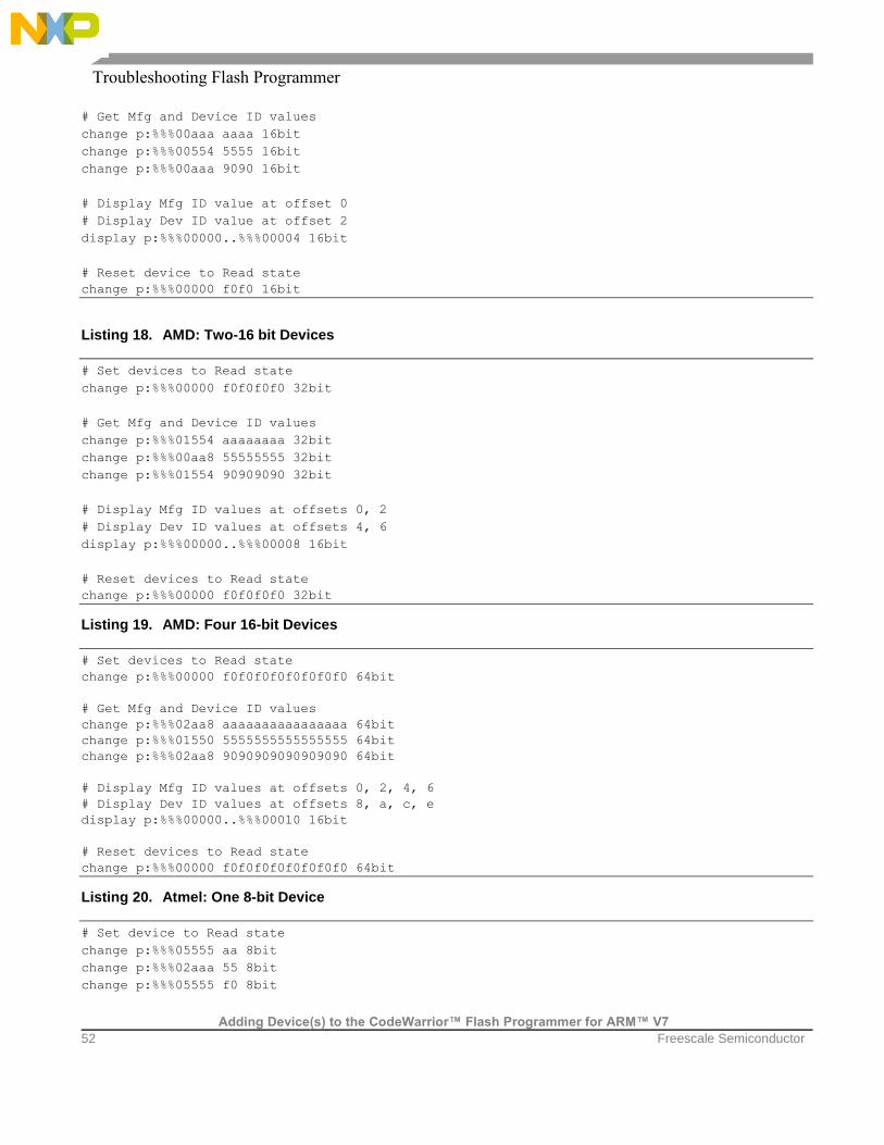
Troubleshooting Flash Programmer
Adding Device(s) to the CodeWarrior™ Flash Programmer for ARM™ V7
52 Freescale Semiconductor
# Get Mfg and Device ID values
change p:%%%00aaa aaaa 16bit
change p:%%%00554 5555 16bit
change p:%%%00aaa 9090 16bit
# Display Mfg ID value at offset 0
# Display Dev ID value at offset 2
display p:%%%00000..%%%00004 16bit
# Reset device to Read state
change p:%%%00000 f0f0 16bit
Listing 18. AMD: Two-16 bit Devices
# Set devices to Read state
change p:%%%00000 f0f0f0f0 32bit
# Get Mfg and Device ID values
change p:%%%01554 aaaaaaaa 32bit
change p:%%%00aa8 55555555 32bit
change p:%%%01554 90909090 32bit
# Display Mfg ID values at offsets 0, 2
# Display Dev ID values at offsets 4, 6
display p:%%%00000..%%%00008 16bit
# Reset devices to Read state
change p:%%%00000 f0f0f0f0 32bit
Listing 19. AMD: Four 16-bit Devices
# Set devices to Read state
change p:%%%00000 f0f0f0f0f0f0f0f0 64bit
# Get Mfg and Device ID values
change p:%%%02aa8 aaaaaaaaaaaaaaaa 64bit
change p:%%%01550 5555555555555555 64bit
change p:%%%02aa8 9090909090909090 64bit
# Display Mfg ID values at offsets 0, 2, 4, 6
# Display Dev ID values at offsets 8, a, c, e
display p:%%%00000..%%%00010 16bit
# Reset devices to Read state
change p:%%%00000 f0f0f0f0f0f0f0f0 64bit
Listing 20. Atmel: One 8-bit Device
# Set device to Read state
change p:%%%05555 aa 8bit
change p:%%%02aaa 55 8bit
change p:%%%05555 f0 8bit

Troubleshooting Flash Programmer
Adding Device(s) to the CodeWarrior™ Flash Programmer for ARM™ V7
Freescale Semiconductor 53
# Get Mfg and Device ID values
change p:%%%05555 aa 8bit
change p:%%%02aaa 55 8bit
change p:%%%05555 90 8bit
# Display Mfg ID value at offset 0
# Display Dev ID value at offset 1
display p:%%%00000..%%%00002 8bit
# Reset device to Read state
change p:%%%05555 aa 8bit
change p:%%%02aaa 55 8bit
change p:%%%05555 f0 8bit
Listing 21. Atmel: Two 8-bit Devices
# Set devices to Read state
change p:%%%0aaaa aaaa 16bit
change p:%%%05554 5555 16bit
change p:%%%0aaaa f0f0 16bit
# Get Mfg and Device ID values
change p:%%%0aaaa aaaa 16bit
change p:%%%05554 5555 16bit
change p:%%%0aaaa 9090 16bit
# Display Mfg ID values at offsets 0, 1
# Display Dev ID values at offsets 2, 3
display p:%%%00000..%%%00004 8bit
# Reset devices to Read state
change p:%%%0aaaa aaaa 16bit
change p:%%%05554 5555 16bit
change p:%%%0aaaa f0f0 16bit
Listing 22. Atmel: Four 8-bit Devices
# Set devices to Read state
change p:%%%15554 aaaaaaaa 32bit
change p:%%%0aaa8 55555555 32bit
change p:%%%15554 f0f0f0f0 32bit
# Get Mfg and Device ID values
change p:%%%15554 aaaaaaaa 32bit
change p:%%%0aaa8 55555555 32bit
change p:%%%15554 90909090 32bit
# Display Mfg ID values at offsets 0, 1, 2, 3
# Display Dev ID values at offsets 4, 5, 6, 7
display p:%%%00000..%%%00008 8bit
# Reset devices to Read state

Troubleshooting Flash Programmer
Adding Device(s) to the CodeWarrior™ Flash Programmer for ARM™ V7
54 Freescale Semiconductor
change p:%%%15554 aaaaaaaa 32bit
change p:%%%0aaa8 55555555 32bit
change p:%%%15554 f0f0f0f0 32bit
Listing 23. Atmel: One 16-bit Device
# Set device to Read state
change p:%%%0aaaa 00aa 16bit
change p:%%%05554 0055 16bit
change p:%%%0aaaa 00f0 16bit
# Get Mfg and Device ID values
change p:%%%0aaaa 00aa 16bit
change p:%%%05554 0055 16bit
change p:%%%0aaaa 0090 16bit
# Display Mfg ID value at offset 0
# Display Dev ID value at offset 2
display p:%%%00000..%%%00004 16bit
# Reset device to Read state
change p:%%%0aaaa 00aa 16bit
change p:%%%05554 0055 16bit
change p:%%%0aaaa 00f0 16bit
Listing 24. Atmel: Two 16-bit Devices
# Set devices to Read state
change p:%%%15554 00aa00aa 32bit
change p:%%%0aaa8 00550055 32bit
change p:%%%15554 00f000f0 32bit
# Get Mfg and Device ID values
change p:%%%15554 00aa00aa 32bit
change p:%%%0aaa8 00550055 32bit
change p:%%%15554 00900090 32bit
# Display Mfg ID values at offsets 0, 2
# Display Dev ID values at offsets 4, 6
display p:%%%00000..%%%00008 16bit
# Reset devices to Read state
change p:%%%15554 00aa00aa 32bit
change p:%%%0aaa8 00550055 32bit
change p:%%%15554 00f000f0 32bit
Listing 25. Atmel: Four 16-bit Devices
# Set devices to Read state
change p:%%%02998 00aa00aa00aa00aa 64bit
change p:%%%01550 0055005500550055 64bit
change p:%%%02aa8 00f000f000f000f0 64bit
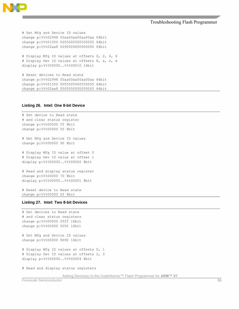
Troubleshooting Flash Programmer
Adding Device(s) to the CodeWarrior™ Flash Programmer for ARM™ V7
Freescale Semiconductor 55
# Get Mfg and Device ID values
change p:%%%02998 00aa00aa00aa00aa 64bit
change p:%%%01550 0055005500550055 64bit
change p:%%%02aa8 0090009000900090 64bit
# Display Mfg ID values at offsets 0, 2, 4, 6
# Display Dev ID values at offsets 8, a, c, e
display p:%%%00000..%%%00010 16bit
# Reset devices to Read state
change p:%%%02998 00aa00aa00aa00aa 64bit
change p:%%%01550 0055005500550055 64bit
change p:%%%02aa8 00f000f000f000f0 64bit
Listing 26. Intel: One 8-bit Device
# Set device to Read state
# and clear status register
change p:%%%00000 ff 8bit
change p:%%%00000 50 8bit
# Get Mfg and Device ID values
change p:%%%00000 90 8bit
# Display Mfg ID value at offset 0
# Display Dev ID value at offset 1
display p:%%%00000..%%%00002 8bit
# Read and display status register
change p:%%%00000 70 8bit
display p:%%%00000..%%%00001 8bit
# Reset device to Read state
change p:%%%00000 ff 8bit
Listing 27. Intel: Two 8-bit Devices
# Set devices to Read state
# and clear status registers
change p:%%%00000 ffff 16bit
change p:%%%00000 5050 16bit
# Get Mfg and Device ID values
change p:%%%00000 9090 16bit
# Display Mfg ID values at offsets 0, 1
# Display Dev ID values at offsets 2, 3
display p:%%%00000..%%%00004 8bit
# Read and display status registers

Troubleshooting Flash Programmer
Adding Device(s) to the CodeWarrior™ Flash Programmer for ARM™ V7
56 Freescale Semiconductor
change p:%%%00000 7070 16bit
display p:%%%00000..%%%00002 8bit
# Reset devices to Read state
change p:%%%00000 ffff 16bit
Listing 28. Intel: Four 8-bit Devices
# Set devices to Read state
# and clear status registers
change p:%%%00000 ffffffff 32bit
change p:%%%00000 50505050 32bit
# Get Mfg and Device ID values
change p:%%%00000 90909090 32bit
# Display Mfg ID values at offsets 0, 1, 2, 3
# Display Dev ID values at offsets 4, 5, 6, 7
display p:%%%00000..%%%00008 8bit
# Read and display status registers
change p:%%%00000 70707070 32bit
display p:%%%00000..%%%00004 8bit
# Reset devices to Read state
change p:%%%00000 ffffffff 32bit
Listing 29. Intel: One 16-bit Device
# Set device to Read state
# and clear status register
change p:%%%00000 ffff 16bit
change p:%%%00000 5050 16bit
# Get Mfg and Device ID values
change p:%%%00000 9090 16bit
# Display Mfg ID value at offset 0
# Display Dev ID value at offset 2
display p:%%%00000..%%%00004 16bit
# Read and display status register
change p:%%%00000 7070 16bit
display p:%%%00000..%%%00002 16bit
# Reset device to Read state
change p:%%%00000 ffff 16bit
Listing 30. Intel: Two 16-bit Devices
# Set devices to Read state
# and clear status registers
change p:%%%00000 ffffffff 32bit
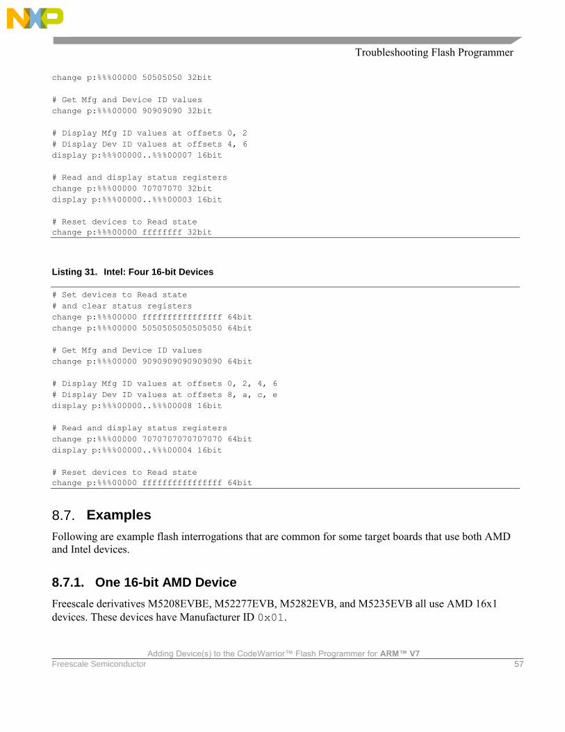
Troubleshooting Flash Programmer
Adding Device(s) to the CodeWarrior™ Flash Programmer for ARM™ V7
Freescale Semiconductor 57
change p:%%%00000 50505050 32bit
# Get Mfg and Device ID values
change p:%%%00000 90909090 32bit
# Display Mfg ID values at offsets 0, 2
# Display Dev ID values at offsets 4, 6
display p:%%%00000..%%%00007 16bit
# Read and display status registers
change p:%%%00000 70707070 32bit
display p:%%%00000..%%%00003 16bit
# Reset devices to Read state
change p:%%%00000 ffffffff 32bit
Listing 31. Intel: Four 16-bit Devices
# Set devices to Read state
# and clear status registers
change p:%%%00000 ffffffffffffffff 64bit
change p:%%%00000 5050505050505050 64bit
# Get Mfg and Device ID values
change p:%%%00000 9090909090909090 64bit
# Display Mfg ID values at offsets 0, 2, 4, 6
# Display Dev ID values at offsets 8, a, c, e
display p:%%%00000..%%%00008 16bit
# Read and display status registers
change p:%%%00000 7070707070707070 64bit
display p:%%%00000..%%%00004 16bit
# Reset devices to Read state
change p:%%%00000 ffffffffffffffff 64bit
8.7. Examples
Following are example flash interrogations that are common for some target boards that use both AMD
and Intel devices.
8.7.1. One 16-bit AMD Device
Freescale derivatives M5208EVBE, M52277EVB, M5282EVB, and M5235EVB all use AMD 16x1
devices. These devices have Manufacturer ID 0x01.

Troubleshooting Flash Programmer
Adding Device(s) to the CodeWarrior™ Flash Programmer for ARM™ V7
58 Freescale Semiconductor
The commands have been executed on a M5235EVB board. For AMD, one device with 16-bit access
instructs the use of Listing 17.
Perform these steps:
1. Copy this code into text file, check_flash.tcl, making the code a script.
2. Substitute the string FFE with all instances of %%%.
3. Use the source command to invoke the script.
Listing 32 shows the resulting code.
NOTE The comment lines in Listing 32 and Listing 33 are for clarification. The CodeWarrior
source command discards comment lines, so you will not see such comments in your
Debugger Shell view.
Listing 32. Example One Results
# Set device to Read state
change p:FFE00000 f0f0 16bit
# Get Mfg and Device ID values
change p:FFE00aaa aaaa 16bit
change p:FFE00554 5555 16bit
change p:FFE00aaa 9090 16bit
# Display Mfg ID value at offset 0
# Display Dev ID value at offset 2
display p:FFE00000..%%%00004 16bit
ffe00000 $0001 $2245 $0000 .. "E ..
# Reset device to Read state
change p:FFE00000 f0f0 16bit
The results of display line show the manufacturer ID code 0x1 and the device ID code 0x2245. This
confirms basic read/write functionality of the flash devices.
8.7.2. One 16-bit Intel Device
Freescale derivatives M5329EVBE, M5373EVB, M5475EVB, and M5485EVB all use AMD 16x1
devices. These devices have Manufacturer ID 0x89.
The commands have been executed on a M5329EVBE board. For Intel, one device with 16-bit access
instructs the use of Listing 29.

Troubleshooting Flash Programmer
Adding Device(s) to the CodeWarrior™ Flash Programmer for ARM™ V7
Freescale Semiconductor 59
Perform these steps:
1. Copy this code into text file, check_flash.tcl, making the code a script.
2. Substitute the string 000 with all instances of %%%.
3. Use the source command to invoke the script.
Listing 33 shows the resulting code.
Listing 33. Example Two Results
# Set device to Read state
# and clear status register
change p:00000000 ffff 16bit
change p:00000000 5050 16bit
# Get Mfg and Device ID values
change p:00000000 9090 16bit
# Display Mfg ID value at offset 0
# Display Dev ID value at offset 2
display p:00000000..%%%00004 16bit
0 $0089 $88C3 $0001 .. .. ..
# Read and display status register
change p:00000000 7070 16bit
display p:00000000..%%%00002 16bit
0 $0080 $0080 .. ..
# Reset device to Read state
change p:00000000 ffff 16bit
The result of the first display line shows the manufacturer ID code 0x0089 and the device ID code
0x88C3. This confirms basic read/write functionality of the flash devices.
8.8. Summary
For most flash devices in use today, programming involves state machine like cycles of multiple writes
that must proceed the final write cycle. To diagnose flash programming failures, you must determine
whether the cause of the failure is in target hardware or flash programming software. The general
method of document lets you make this determination through simple, low level writes and reads,
without the use of expensive and complicated logic analyzers. If these reads and writes fail, the problem
most likely is on the target. If these reads and writes succeed, the problem most likely is in the flash
programming software, so contact Technical Support at http://www.freescale.com/support.

Troubleshooting Flash Programmer
Adding Device(s) to the CodeWarrior™ Flash Programmer for ARM™ V7
60 Freescale Semiconductor


Document Number: AN4349 12 December 2014
Information in this document is provided solely to enable system and software implementers to use Freescale Semiconductor products. There are no express or implied copyright licenses granted hereunder to design or fabricate any integrated circuits or integrated circuits based on the information in this document. Freescale Semiconductor reserves the right to make changes without further notice to any products herein. Freescale Semiconductor makes no warranty, representation or guarantee regarding the suitability of its products for any particular purpose, nor does Freescale Semiconductor assume any liability arising out of the application or use of any product or circuit, and specifically disclaims any and all liability, including without limitation consequential or incidental damages. “Typical” parameters that may be provided in Freescale Semiconductor data sheets and/or specifications can and do vary in different applications and actual performance may vary over time. All operating parameters, including “Typicals”, must be validated for each customer application by customer’s technical experts. Freescale Semiconductor does not convey any license under its patent rights nor the rights of others. Freescale Semiconductor products are not designed, intended, or authorized for use as components in systems intended for surgical implant into the body, or other applications intended to support or sustain life, or for any other application in which the failure of the Freescale Semiconductor product could create a situation where personal injury or death may occur. Should Buyer purchase or use Freescale Semiconductor products for any such unintended or unauthorized application, Buyer shall indemnify and hold Freescale Semiconductor and its officers, employees, subsidiaries, affiliates, and distributors harmless against all claims, costs, damages, and expenses, and reasonable attorney fees arising out of, directly or indirectly, any claim of personal injury or death associated with such unintended or unauthorized use, even if such claim alleges that Freescale Semiconductor was negligent regarding the design or manufacture of the part. Freescale, the Freescale logo, CodeWarrior, and QorIQ are trademarks of Freescale Semiconductor, Inc., Reg. U.S. Pat. & Tm. Off. Layerscape is trademark of Freescale Semiconductor, Inc. All other product or service names are the property of their respective owners. ARM, Cortex, Cortex-A7, TrustZone are trademarks of ARM Limited (or its subsidiaries) in the EU and/or elsewhere. All rights reserved. © Freescale Semiconductor, Inc. 2014. All rights reserved.