an overview of depth imaging in exploration geophysics - · pdf filean overview of depth...
TRANSCRIPT
A
J
trs
©
GEOPHYSICS, VOL. 74, NO. 6 �NOVEMBER-DECEMBER 2009�; P. WCA5–WCA17, 8 FIGS.10.1190/1.3223188
n overview of depth imaging in exploration geophysics
ohn Etgen1, Samuel H. Gray2, and Yu Zhang3
ltmvtaFebt
waalitaefs
ftRededaaepqp
w
eceivedn.etgen
m..
ABSTRACT
Prestack depth migration is the most glamorous step ofseismic processing because it transforms mere data into animage, and that image is considered to be an accurate struc-tural description of the earth. Thus, our expectations of its ac-curacy, robustness, and reliability are high. Amazingly, seis-mic migration usually delivers. The past few decades haveseen migration move from its heuristic roots to mathemati-cally sound techniques that, using relatively few assump-tions, render accurate pictures of the interior of the earth. In-terestingly, the earth and the subjects we want to image insideit are varied enough that, so far, no single migration techniquehas dominated practical application. All techniques continu-ally improve and borrow from each other, so one techniquemay never dominate. Despite the progress in structural imag-ing, we have not reached the point where seismic images pro-vide quantitatively accurate descriptions of rocks and fluids.Nor have we attained the goal of using migration as part of apurely computational process to determine subsurface veloc-ity. In areas where images have the highest quality, we mightbe nearing those goals, collectively called inversion. Wheredata are more challenging, the goals seem elusive. We de-scribe the progress made in depth migration to the presentand the most significant barriers to attaining its inversiongoals in the future.We also conjecture on progress likely to bemade in the years ahead and on challenges that migrationmight not be able to meet.
INTRODUCTION
The ultimate and perhaps unattainable goal of seismic imaging iso replace the art of interpretation with a computational process thatenders quantitatively accurate models of the subsurface. Migrationtarted out with a much more humble goal — to position reflectors
Manuscript received by the Editor 26 February 2009; revised manuscript r1BPAmerica, E&PTechnology Group, Houston, Texas, U.S.A. E-mail: joh2CGGVeritas, Calgary,Alberta, Canada. E-mail: [email protected], Houston, Texas, U.S.A. E-mail: [email protected] Society of Exploration Geophysicists.All rights reserved.
WCA5
Downloaded 10 Feb 2010 to 24.149.197.34. Redistribution subject to S
aterally, accurately enough for exploration with a drill bit. Overime, migration became more ambitious; with the advent of depthigration, we began to think of seismic imaging as a process to pro-
ide a picture of the interior of the earth, not just a drill location onhe surface. Even if we neglect some of the obvious difficulties suchs anisotropy, substantial progress has been made in this direction.or this to happen, migration needed velocity information to a great-r extent than other seismic processing steps. So, a love-hate affairetween migration and velocity estimation was born, one that con-inues to this day.
If migration were capable of producing only a structural image, itould of course be more limited than it is; but migration amplitude
nalysis can, in principle, exceed structural imaging. Many yearsgo, people began exploring for bright spots, or amplitude anoma-ies on seismic images. Shortly after, it was realized that migratedmages contain amplitudes that are in some way related to the reflec-ivity strength of the reflectors being imaged. Although in good datareas a migrated image can be interpreted for structure �and possiblyven for velocity� with ease, turning the qualitative amplitude ef-ects observed in the image into quantitative properties of the sub-urface has always been more problematic.
There are many reasons for this. One of the most obvious is that,rom a seismic processing perspective, most of the imaging opera-ors are not inversion operators but technically are adjoint operators.oughly speaking, migration/inversion operators invert the seismicxperiment to produce earth-related properties such as angle-depen-ent reflection coefficients. Migration/adjoint operators, on the oth-r hand, only undo the kinematics of the seismic experiment to pro-uce the earth properties with an unspecified spatially varying filterpplied. Various reasons justify the claim that the imaging operatorsre not really inversions: incomplete coverage of sources and receiv-rs, incomplete subsurface illumination caused by velocity com-lexities in the overburden, and mathematical requirements that re-uire downward-continued wavefields with evanescent decay hap-ening in the wrong direction.Of course, this limitation was recognized early on, and many
orkers describe techniques to improve the amplitude treatment of
8 May 2009; published online 15 December [email protected].
EG license or copyright; see Terms of Use at http://segdl.org/
mhmhsifvat
dpkmnatdqstt
mpotsp
tipaggstntsttttc
mmtmmgado
i�wf
tascmmmdbmesg
R
okitBti
dpiK
wclctci
tlsstrcmTbbrgev
WCA6 Etgen et al.
igration, upgrading to the status of inversion. In some areas of veryigh-quality seismic reflection signals, the upgraded migrationethods have some track record of success. In many other areas,
owever, we still fall far short of the goal of rendering a quantitativeubsurface image directly.Although it is routine to analyze migratedmages for amplitude effects �versus offset or angle�, we usually arear less confident in this than we are in estimating long-wavelengthelocity. There is almost always an interpretive facet to migratedmplitude analysis, and relationships usually are empirical, not de-erministic.
So, where do we head in the future with migrated kinematics andynamics? Obviously, when the overburden above our target is com-lex, we need wavefield-continuation methods that provide accurateinematic imaging. This has led to the popularity of wave-equationethods, including reverse-time migration �RTM�. Meanwhile, the
eed to derive an accurate velocity model has led to ray-theoreticnd, more recently, wave-theoretic techniques for velocity estima-ion. We also need to be more careful with amplitude preservationuring the entire imaging process to have any hope of obtaininguantitative images. This means we need to apply amplitude-pre-erving migration to data whose unmigrated amplitudes are consis-ent with the wave-propagation theory underlying the migration andhe actual seismic experiment.
In the next sections, we add a certain amount of detail to this sum-ary and speculate whether some of our proposed solutions to the
roblems can work. Our subject is broad and deep, with many layersf detail in almost all of the topics. In this overview, we can attempto hit only the high points of the theory, practice, and goals of main-tream depth imaging and inversion for seismic velocity and rockroperties.
WHERE WE ARE AND HOW WE GOT HERE
The current state of the art in depth imaging is the routine produc-ion use of 3D prestack depth migration for marine and land data, us-ng one or more imaging methods. The migration process has threeurposes: to estimate migration velocity, to produce a structural im-ge, and to render an image whose amplitudes or other attributesive an interpreter clues about rock and fluid properties. Depth mi-ration needs a nearly correct velocity model to produce a correcttructural image and to focus stratigraphic details, so using migra-ion to estimate velocity �which is needed for migration� presents aonlinear problem. Seismic tomography, the current popular solu-ion to this nonlinear velocity/imaging problem, is iterative, using auccession of migration iterations in combination with an optimiza-ion routine to build and refine the velocity model. Not yet routine ishe incorporation of migration into waveform inversion schemeshat estimate earth parameters such as velocity, density, and aniso-ropy. We first concentrate on the migration methods; later, we dis-uss the nonlinear imaging/velocity estimation problem.
There are two major classes of migration methods: ray-basedethods and wave-equation-based methods. In fact, even ray-basedigrations are based on the wave equation, but we follow conven-
ion by saving the term wave-equation migration for nonray-basedigration methods. Within the major classes are many individualethods. Ray-based methods are Kirchhoff migration and beam mi-
rations. Wave-equation methods fall into major classes, one waynd two way, with many different one-way wave-equation methodseveloped over more than three decades. Although all of the meth-ds can be described in terms of wavefield continuation followed by
Downloaded 10 Feb 2010 to 24.149.197.34. Redistribution subject to S
maging, we describe ray methods in terms of migrating individualgroups of� traces separately and �with some abuse of terminology�ave-equation methods as downward-continuing entire wavefields,
ollowed by imaging.Because rays represent an asymptotic solution to the wave equa-
ion, we are tempted to expect wave-equation methods to be moreccurate than ray methods and to produce better images of the earth’subsurface. However, neither of these expectations is necessarilyorrect. Generally, wave-equation methods are more accurate thanost ray-based methods within their range of applicability, whichight be quite limited. Only when the structural-imaging situation isodeled well by a particular wave-equation method can we confi-
ently expect the wave-equation image to be better than the best ray-ased image. For example, overturned events can be imaged byany ray-based migrations. But such events are not modeled prop-
rly by upward-continuation �one-way wave-equation� modeling,o we cannot expect that downward-continuation migration will mi-rate them properly.
ay-based migration methods
Kirchhoff migration is the most familiar of the ray-based meth-ds. Publications by French �1975� and Schneider �1978� elevate theinematic operation of diffraction stack to the status of an asymptot-cally correct solution to the problem of imaging by downward-con-inuing a seismic wavefield. Further work �e.g., Beylkin, 1985;leistein, 1987; Bleistein et al., 2001� develops and summarizes
rue-amplitude Kirchhoff migration, and several other workersnvestigated various schemes for ray-based traveltimes.
From the late 1980s to the late 1990s, Kirchhoff migration was theominant depth-imaging method. Its formulation as an integral ap-roximate solution to the wave equation explicitly shows how eachnput trace contributes to the complete image. The common-shotirchhoff migration expression, for example, is given by
I�x;xs���dxr�dtW� pU�xr;xs;t�
� t� �t� �ts� tr��, �1�
here x is the image location, xs is the source location, xr are the re-eiver locations, ts and tr are traveltimes from the source and receiverocations to the image location, W is a weight function, pU is the re-orded wavefield, and � is the Dirac delta function. Approximatinghe integral over receiver locations by a summation shows how to ac-umulate a data sample from a particular receiver location into themage at location x.
Equation 1 demonstrates the great flexibility of Kirchhoff migra-ion in several ways. First, the image needs to be calculated only atocations x chosen by the user. That set of locations can be an entireeismic volume or it can be any desired subset of the volume. Thepatial sampling of the image can differ from the spatial sampling ofhe recorded traces. Second, input traces from any subvolume of theeceiver spread can be selected to contribute to the image. Thehoice of input data and output volume for each input trace defines aigration aperture, and this aperture can be arbitrarily large or small.hird, data samples from any subset of the entire recording time cane selected to contribute to the image. If traveltimes are calculatedy ray tracing, the ray tracing can be restricted to include a desiredange of incidence angles at the recording surface or propagation an-les in the subsurface. If the range of propagation angles is widenough, then Kirchhoff migration can image very steep dips; con-ersely, limiting the range of angles in moderate-dip areas often al-
EG license or copyright; see Terms of Use at http://segdl.org/
llbt
Kpalmpcsmnabm�suea
enhcomaWtlgmHtmttus
tnamr
teeKucntTn
mctt
tdiipwtbpdrsmrpt
ttfmfTq
stmlHffilp
Fpdis
Depth imaging overview WCA7
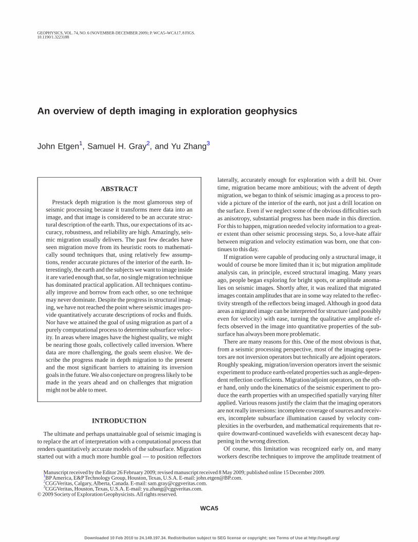
ows Kirchhoff migration to produce clean images very economical-y. Fourth, if ray angles are tracked through the subsurface, they cane used to compute quantities such as subsurface opening angles orhe geologic dip imaged by a particular trace �Figure 1�.
On closer inspection, equation 1 also shows the limitations ofirchhoff migration. Most fundamentally, using ray tracing to com-ute traveltimes can limit the contribution of an input trace to the im-ge. The wavefield at an image location from a source or a receiverocation, which is approximated by an arrival along a single raypath,ight not be represented well by the single amplitude arriving at a
articular time implied by equation 1. Alternatively, one mighthoose to accumulate contributions from several raypaths from aource or receiver location at an image location; however, this is farore complicated than accumulating a single arrival. For conve-
ience, most production Kirchhoff migration programs use singlerrivals — often the earliest arrival or the most energetic arrivalased on ray-tube spreading. �Notable exceptions show improve-ent over single-arrival Kirchhoff migration, e.g., Operto et al.
2000� and Koren et al. �2008�.� Single-valued traveltime functionsuffer from the problem of frequent discontinuities, which contrib-te noise to the final image. Finally, in extremely complex areas,ven several ray arrivals might not describe the complete wavefielddequately.
Do the limitations of Kirchhoff migration outweigh its advantag-s?Yes and no. Most current marine depth migration projects culmi-ate with a final image produced by some method other than Kirch-off. Wave-equation methods and beam methods tend to produceleaner, more interpretable images than Kirchhoff migration. On thether hand, Kirchhoff migration is commonly used to build velocityodels. One might ask, “If Kirchhoff migration is unsuitable for im-
ging in complex areas, can it be adequate for building models?”hatever the answer to that question, the industry has not replaced
he standard depth-migration flow of iterations of migration fol-owed by ray-based tomography with Kirchhoff as the migration en-ine because of its efficiency and its ability to output migrated com-on-image gathers �CIGs� that seismic tomography can use easily.owever, these are not compelling reasons to use Kirchhoff migra-
ion, and seismic wavefield tomography and waveform inversionethods are emerging. These methods are based on wavefield ex-
rapolation, not ray tracing. If they replace ray-based tomography inhe flow, we can state confidently that Kirchhoff migration will bensuitable for most marine projects with complicated geologictructure.
Recently, wide-azimuth marine acquisition has extended greatlyhe recording aperture of the data in one direction �which, for conve-ience, we call the crossline direction�. This has affected migrationlgorithms in ways that change the relative efficiency of migrationethods, with the result that Kirchhoff migration can be inefficient
elative to wave-equation methods. This happens for two reasons.The first reason concerns aperture. For narrow-azimuth acquisi-
ion, the input �recording� aperture in the crossline direction is thextent of the recorded data. When the output �imaging� crossline ap-rture is much wider than the crossline extent of the recorded data,irchhoff migration swings the recorded traces into the image vol-me. Wave-equation migration, on the other hand, must downward-ontinue a wavefield within the entire imaging aperture, even whereo traces have been recorded. It does this by padding the input aper-ure with zero traces before beginning the downward continuation.his extra size added to the wavefield contributes significantly to theumber of operations in the downward continuation. For wide-azi-
Downloaded 10 Feb 2010 to 24.149.197.34. Redistribution subject to S
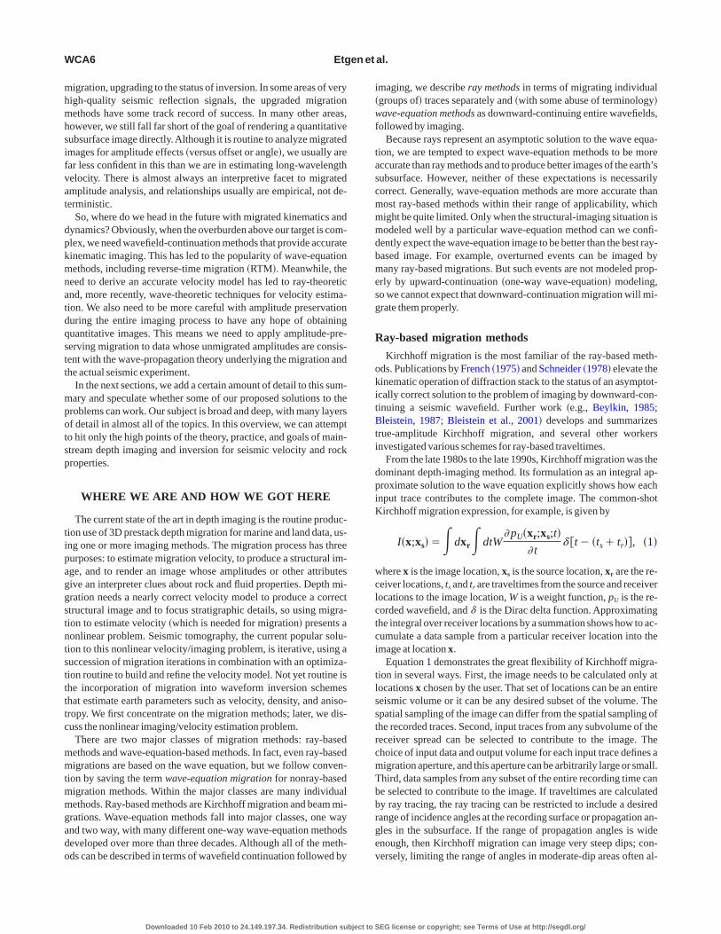
uth acquisition, the input crossline aperture is a much greater per-entage of the imaging crossline aperture, and wave-equation migra-ion spends far less of its effort downward-continuing zero traces,hus gaining efficiency relative to Kirchhoff migration �Figure 2�.
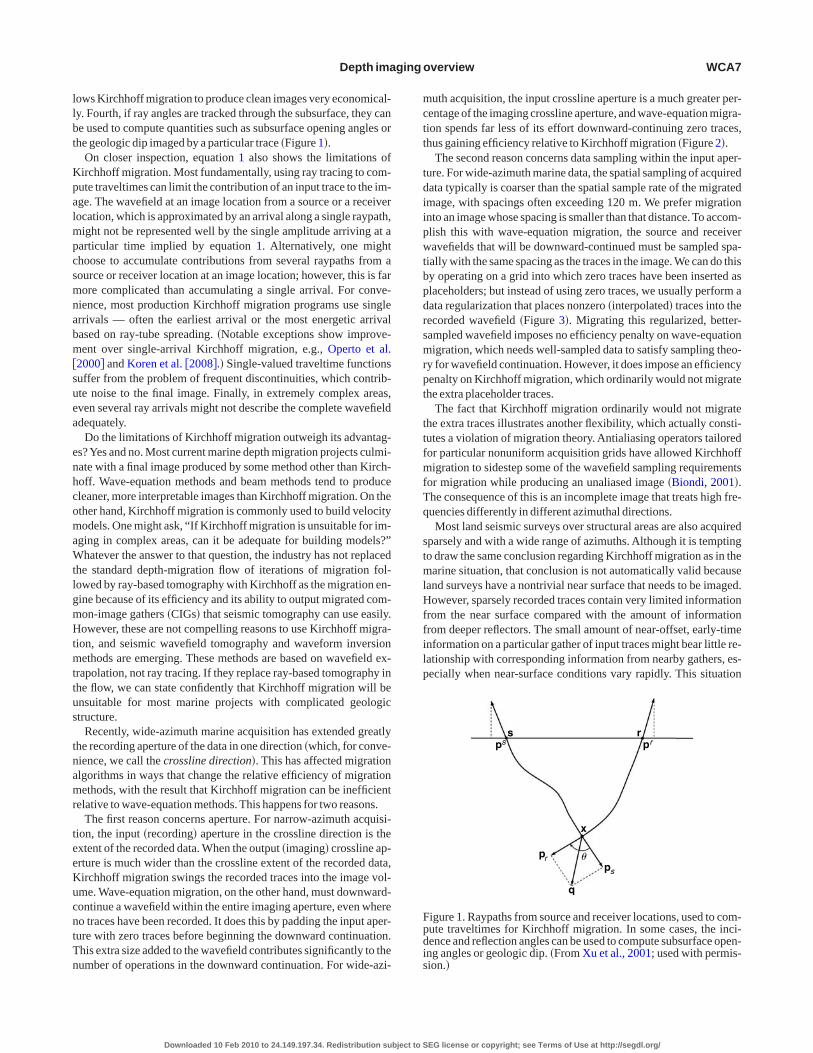
The second reason concerns data sampling within the input aper-ure. For wide-azimuth marine data, the spatial sampling of acquiredata typically is coarser than the spatial sample rate of the migratedmage, with spacings often exceeding 120 m. We prefer migrationnto an image whose spacing is smaller than that distance. To accom-lish this with wave-equation migration, the source and receiveravefields that will be downward-continued must be sampled spa-
ially with the same spacing as the traces in the image. We can do thisy operating on a grid into which zero traces have been inserted aslaceholders; but instead of using zero traces, we usually perform aata regularization that places nonzero �interpolated� traces into theecorded wavefield �Figure 3�. Migrating this regularized, better-ampled wavefield imposes no efficiency penalty on wave-equationigration, which needs well-sampled data to satisfy sampling theo-
y for wavefield continuation. However, it does impose an efficiencyenalty on Kirchhoff migration, which ordinarily would not migratehe extra placeholder traces.
The fact that Kirchhoff migration ordinarily would not migratehe extra traces illustrates another flexibility, which actually consti-utes a violation of migration theory. Antialiasing operators tailoredor particular nonuniform acquisition grids have allowed Kirchhoffigration to sidestep some of the wavefield sampling requirements
or migration while producing an unaliased image �Biondi, 2001�.he consequence of this is an incomplete image that treats high fre-uencies differently in different azimuthal directions.Most land seismic surveys over structural areas are also acquired
parsely and with a wide range of azimuths. Although it is temptingo draw the same conclusion regarding Kirchhoff migration as in thearine situation, that conclusion is not automatically valid because
and surveys have a nontrivial near surface that needs to be imaged.owever, sparsely recorded traces contain very limited information
rom the near surface compared with the amount of informationrom deeper reflectors. The small amount of near-offset, early-timenformation on a particular gather of input traces might bear little re-ationship with corresponding information from nearby gathers, es-ecially when near-surface conditions vary rapidly. This situation
s rpp
x
pp
q
s r
r
s
�
igure 1. Raypaths from source and receiver locations, used to com-ute traveltimes for Kirchhoff migration. In some cases, the inci-ence and reflection angles can be used to compute subsurface open-ng angles or geologic dip. �From Xu et al., 2001; used with permis-ion.�
EG license or copyright; see Terms of Use at http://segdl.org/
pwwopa2
trfttnomtitpdo
wit—btwtcgdot
Ww
mpeittrwtg
dww
a
b
Ftebtnsm
FwsRicsne
WCA8 Etgen et al.
oses problems for the data interpolation/regularization needed forave-equation migration, in turn limiting the potential uplift ofave-equation migration over Kirchhoff for near-surface imagingf typical land data. Despite this limitation, some experiments com-aring Kirchhoff with wave-equation and beam images in overthrustreas show promise for advanced imaging techniques �Bale et al.,007�.Beam migrations are, at their core, directional Kirchhoff migra-
ions performed on spatial windows of the recorded data. Most cur-ent beam migrations are not limited to single-valued traveltimeunctions, with their potential to contribute noise from discontinui-ies to the migrated image, and they have potential efficiency advan-ages over Kirchhoff migration. Sun et al. �2000� describe the tech-ique in elementary terms: “The migration of a supergather consistsf two major steps: stacking the traces into a � -p beam volume, andapping the beams into the image volume.” Hill �2001� formalizes
he method as a wave-equation migration that uses ray-based Gauss-an beams as a wavefield extrapolator. He provides rules, all withinhe framework of wavefield continuation, for �1� distributing the in-ut traces into supergathers, or overlapping tapered spatial win-ows; �2� decomposing the spatial windows into individual beams,r directional components; and �3� mapping the beams.
)
)
igure 2. Narrow-azimuth acquisition versus wide-azimuth acquisi-ion. �a� For wave-equation migration whose crossline imaging ap-rture �in gray� exceeds the narrow-azimuth recording aperture �inlue�, the migration must insert zero traces as placeholders outsidehe recording aperture, adding to the cost of the migration.This is un-ecessary for Kirchhoff migration. �b� Wide-azimuth acquisitionignificantly reduces this efficiency disadvantage for wave-equationigration.
Downloaded 10 Feb 2010 to 24.149.197.34. Redistribution subject to S
Beam migrations map the directional components of the recordedavefield into the image volume independently of one another. The
mages of the components can overlap each other in space. That way,hey overcome a major limitation of standard Kirchhoff migration
namely, its restriction to single-valued traveltimes. For Gaussianeam migration, the complex-valued paraxial wavefields near cen-ral raypaths give a smooth decay to the individual beam images asell as smoother amplitudes �more consistent with the wave equa-
ion� than standard Kirchhoff migration. Therefore, beam migration,arefully implemented, is usually superior to standard Kirchhoff mi-ration for well-sampled data. In addition, beam migrations are notip limited, giving them an advantage over migrations based on thene-way wave equation. However, the reliance of most beam migra-ions on rays can limit their accuracy in structurally complex areas.
ave-equation migration methods — The one-wayave equation
Wave-equation migrations are one way or two way. One-wayethods apply Green’s identity, which expresses a wavefield at a
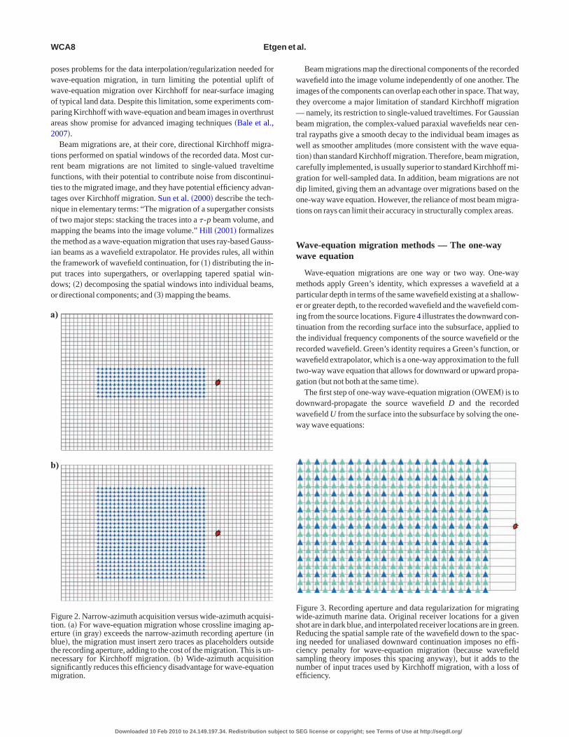
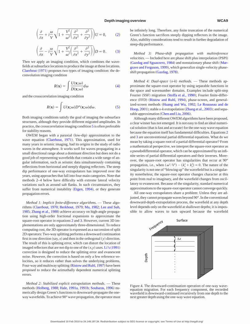
articular depth in terms of the same wavefield existing at a shallow-r or greater depth, to the recorded wavefield and the wavefield com-ng from the source locations. Figure 4 illustrates the downward con-inuation from the recording surface into the subsurface, applied tohe individual frequency components of the source wavefield or theecorded wavefield. Green’s identity requires a Green’s function, oravefield extrapolator, which is a one-way approximation to the full
wo-way wave equation that allows for downward or upward propa-ation �but not both at the same time�.The first step of one-way wave-equation migration �OWEM� is to
ownward-propagate the source wavefield D and the recordedavefield U from the surface into the subsurface by solving the one-ay wave equations:
igure 3. Recording aperture and data regularization for migratingide-azimuth marine data. Original receiver locations for a given
hot are in dark blue, and interpolated receiver locations are in green.educing the spatial sample rate of the wavefield down to the spac-
ng needed for unaliased downward continuation imposes no effi-iency penalty for wave-equation migration �because wavefieldampling theory imposes this spacing anyway�, but it adds to theumber of input traces used by Kirchhoff migration, with a loss offficiency.
EG license or copyright; see Terms of Use at http://segdl.org/
TfiCc
a
Bspf
wmwsggrdymvsp
r1tspc2fiTicnlFpe
mmw
bGAs
v�gs
ptFeiHr
acbamaanopsipla
jdls
Fewn
Depth imaging overview WCA9
� �
� z� i
�
V�1�
V2
�2� � 2
�x2 �� 2
� y2��U�0, �2�
� �
� z� i
�
V�1�
V2
�2� � 2
�x2 �� 2
� y2��D�0. �3�
hen we apply an imaging condition, which combines the wave-elds at subsurface locations to produce the image at those locations.laerbout �1971� proposes two types of imaging condition: the de-onvolution imaging condition
R�x��� U�x;��D�x;��
d� �4�
nd the crosscorrelation imaging condition
R�x���U�x;��D*�x;��d� . �5�
oth imaging conditions satisfy the goal of imaging the subsurfacetructures, although they provide different migrated amplitudes. Inractice, the crosscorrelation imaging condition 5 is often preferableor stability reasons.
OWEM began with a paraxial �low-dip� approximation to theave equation �Claerbout, 1971�. This approximation, used forany years in seismic imaging, had its origins in the study of radioaves in the atmosphere. It works well for waves propagating in a
mall directional range about a dominant direction but does not do aood job of representing wavefields that contain a wide range of an-ular information, such as seismic data simultaneously containingeflections from horizontal and steeply dipping reflectors. The steepip performance of one-way extrapolators has improved over theears, using approaches that fall into four main categories. Note thatethods 2–4 below have difficulty with extreme lateral velocity
ariations such as around salt flanks. In such circumstances, theyuffer from numerical instability �Etgen, 1994�, or they generateropagation errors.
Method 1: Implicit finite-difference algorithms. — These algo-ithms �Claerbout, 1970; Berkhout, 1979; Ma, 1982; Lee and Suh,985; Zhang et al., 1988� achieve accuracy on high-angle propaga-ion using high-order fractional expansions to approximate thequare-root operator in equations 2 and 3. However, current 3D im-lementations are only approximately three-dimensional. To reduceomputing cost, the 3D operator is expressed as a succession of splitD operators: Two-way splitting performs a downward continuationrst in one direction �say, x� and then in the orthogonal �y� direction.he result of this is splitting error, which can distort the location of
maged reflectors that are not dip to one of the �x,y� axes. Li’s �1991�orrection is designed to reduce the splitting error and evanescentoise. However, the correction is based on only a few reference ve-ocities, so it reduces rather than solves the underlying problems.our-way and multiway splitting �Ristow and Ruhl, 1997� have beenroposed to reduce the azimuthally dependent numerical splittingrrors.
Method 2: Stabilized explicit extrapolation methods. — Theseethods �Holberg, 1988; Hale, 1991a, 1991b; Soubaras, 1996� nu-erically design Green’s functions to downward-propagate the one-ay wavefields.To achieve 90° wave propagation, the operator must
Downloaded 10 Feb 2010 to 24.149.197.34. Redistribution subject to S
e infinitely long. Therefore, any finite truncation of the numericalreen’s function sacrifices steeply dipping reflectors in the image.lso, stability considerations tend to result in further degradation of
teep-dip performance.
Method 3: Phase-shift propagation with multireferenceelocities. — Included here are phase shift plus interpolation �PSPI�Gazdag and Sguazzero, 1984� and nonstationary phase shift �Mar-rave and Ferguson, 1999�, which generalize single-velocity phase-hift propagation �Gazdag, 1978�.
Method 4: Dual-space �x-k� methods. — These methods ap-roximate the square-root operator by using separable functions inhe space and wavenumber domains. Examples include split-stepourier �SSF� migration �Stoffa et al., 1990�; Fourier finite-differ-nce �FFD� �Ristow and Ruhl, 1994�, phase-screen, and general-zed-screen methods �Huang and Wu, 1992; Le Rousseau and deoop, 2001�; stable x-k extrapolation �Zhang et al., 2003�; and sepa-
able approximation �Chen and Liu, 2006�.Although many different OWEM algorithms have been proposed,
clear winner has not emerged. It is not easy to find an ideal numeri-al solution �that is fast and accurate� for the one-way wave equationecause the equation itself has fundamental difficulties. Equations 2nd 3 are unconventional partial differential equations. What do weean by taking a square root of a partial differential operator? Frommathematical perspective, we interpret the square-root operator aspseudodifferential operator, which can be approximated by an infi-ite series of partial differential operators and their inverses. More-ver, the square-root operator has singularities that occur at 90°ropagation, i.e., when ��2 /V2�� �kx
2�ky2��0. The nature of the
ingularity is not one of “blowing up” the wavefield but is a singular-ty nonetheless; the square-root operator changes character at thisoint from real to imaginary, and the wavefield changes from oscil-atory to evanescent. Because of the singularity, standard numericalpproximations to the square-root operator cannot converge quickly.
All one-way extrapolators share a problem: Unless they are ad-usted, they cannot propagate waves beyond 90°. In the conventionalownward-depth-extrapolation process, the wavefield at any depthevel depends only on the wavefield at shallower depths; it is impos-ible to allow waves to turn upward because the wavefield
z
igure 4. The downward-continuation operation of one-way wave-quation migration. For each frequency component, the recordedavefield is downward-continued recursively from one depth to theext greater depth using the one-way wave equation.
EG license or copyright; see Terms of Use at http://segdl.org/

w“9
pplsamita
ofptvotl�mdrtagat
aKvc�f
ctt
ssm
Td2e�1Cts
Ww
tMmiewsfespt
er
Ufnoewwim
stoo
Fwgjepvsw
WCA10 Etgen et al.
ould need knowledge of its state at greater depth levels. Twotweaks” allow one-way extrapolators to propagate waves beyond0°.First, Claerbout �1985� modifies poststack phase-shift migration,
erforming it in two passes: down and then back up. The downwardass preserves the energy that would be evanescent in the next depthayer, saving nearly horizontally propagating energy at each depthtep. The second pass uses this saved wavefield and introduces it inton upward-continued wavefield extrapolated from the bottom of theodel to the top. Combining the two images produces a composite
mage containing dips exceeding 90°. Hale et al. �1992� apply thisechnique to image very steep dips on poststack data, and Zhang etl. �2006� extend it to prestack migration in a laterally varying earth.
Second, others apply tilted coordinate systems to extrapolationperators to change the preferred direction of propagation awayrom vertical �Higginbotham et al., 1985�. The tilted-coordinate ap-roach has been modified to produce prestack migration methodshat can capitalize on a preferred direction of propagation other thanertical �e.g., the plane-wave migration method of Whitmore �1995�r Rietveld and Berkhout �1994�; without tilting the coordinate sys-em, however, OWEM versions of plane-wave migration are still dipimited�. Etgen and Brandsberg-Dahl �2002� and Shan and Biondi2008� introduce this approach, coining the phrase tilted plane-waveigration. To image all possible dips, their method requires severalifferent tilted grids, each oriented to some preferred propagation di-ection, usually corresponding to a compromise between the sourceake-off angle and the expected geologic dip. Indeed, this tilted prop-gation approach has been applied successfully to shot-record mi-ration, when there are steep or overturned dips in the image in onlyfew orientations, removing the requirement of tilting the propaga-
ion direction in every possible direction �Nolte et al., 2008�.Before 2000, OWEM was applied widely �but not universally� as
n intuitive and rough way of performance seismic inversion, unlikeirchhoff migration, which is supported by modern amplitude in-ersion theory �Bleistein et al., 2001�, keeping in mind our earlieromments on the practical limitations on this theory. Zhang et al.2005� show that by calibrating the one-way equations and the sur-ace conditions, OWEM can produce true-amplitude migration
t t
t t
igure 5. The operation of reverse-time migration on the recordedavefield, illustrated schematically in two space dimensions. Be-inning with the maximum recorded time tmax, the wavefield is in-ected from the recording surface into the subsurface, then propagat-d backward in time until time zero. The full acoustic wave equationropagates energy downward and upward within the computationalolume. At each time step, a vertical slice through the cube shows anapshot of the wavefield. This wavefield is then crosscorrelatedith the source wavefield, which has propagated forward in time.
Downloaded 10 Feb 2010 to 24.149.197.34. Redistribution subject to S
ommon-shot common image gathers �CIGs� under the deconvolu-ion imaging condition 4. The result should be as good as or betterhan that from a Kirchhoff true-amplitude migration.
A key issue in true-amplitude OWEM work is to interpret thequare-root operator properly and to ensure that the equation pre-erves propagation energy. For example, equation 2 needs to beodified as
� �
� z� i
�
V�1�
1
�2�V�
�x�2
��V�
� y�2�
1
2V
�V
� z
��2��V�
�x�2
��V�
� y�2�1
�2�U�0. �6�
he lateral derivatives appearing under the radical are important foresigning a stable one-way propagator. This explains why methods-4 above cannot handle sharp velocity boundaries correctly; the lat-ral velocity gradient is absent in those algorithms. Zhang et al.2007� prove that imaging condition 5, proposed by Claerbout in971, also provides a true-amplitude migration result if the outputIGs are in the reflection-angle domain. Therefore, the imaging in-
uitions of pioneer geophysicists are well explained and settled on aolid theoretical base.
ave-equation migration methods — The two-wayave equation
The full two-way wave equation first was used for depth migra-ion of 2D poststack data in the late 1970s �Baysal et al., 1983; Mc-
echan, 1983; Whitmore, 1983�. This method is called reverse-timeigration �RTM� because it propagates the recorded wavefield from
ts boundary �the recording surface� into the earth using the full wavequation with time running backward �Figure 5�. Its use of the fullave equation, not Green’s identity, requires that it compute snap-
hots of the entire wavefield everywhere inside the earth at all timesrom the latest time to time zero. �For prestack migration, the record-d wavefield is still propagated backward in time. However, theource wavefield is created by propagating forward in time, so therestack migration algorithm should be called forward and reverseime migration.�
If we consider seismic waves to be acoustic, then the propagationngine in acoustic RTM is the most accurate we can get. Here, we di-ectly solve the two-way acoustic wave equation:
� 1
V2
� 2
� t2�
� 2
�x2 �� 2
� y2 �� 2
� z2�p�x;t��0. �7�
nlike Kirchhoff migration and beam migration, there is no high-requency assumption in equation 7. And unlike OWEM, there areo approximations to the wave equation that limit propagation angler the ability to handle strong lateral velocity variations. So RTM canasily handle any spatial velocity variation to produce all kinds ofaves �reflections, refractions, diffractions, multiples, evanescentaves�. Also, RTM propagates waves in all possible directions, and
ts ability to image dips up to 180° gives it an advantage over otherethods.From an implementation perspective, it is easier and more
traightforward to solve the well-behaved partial differential equa-ion 7 than expressions such as equation 6 with its pseudodifferentialperators.Ahigh-order difference method or a pseudospectral meth-d �Kosloff and Baysal, 1982; Etgen, 1986� can achieve high accura-
EG license or copyright; see Terms of Use at http://segdl.org/
catrr�ted3mc
wdaaRsennOtpg
wtsfrdtcptca�a
msensc2da2a
bietfm
hemcmaana
I
BttefRtesi
s2gtrweswip
Ca
efmeawoteuKbtn
mTimma
Depth imaging overview WCA11
y and avoid numerical dispersion. However, since its introductionbout three decades ago, RTM has fallen in and out of use severalimes. Each time it went out, the reasons usually involved memoryequirements and efficiency compared to other methods. The memo-y requirements for Kirchhoff and beam migration can be minimalsmall set of input traces, output aperture, traveltimes and ampli-udes�, and OWEM asks only for several 2D arrays �frequency slic-s� to extrapolate the wavefields in the frequency domain from oneepth step to another. However, 3D RTM works only when severalD arrays �wavefield snapshots at several time steps plus velocityodel�s�� are allocated for it, which was a luxury requirement for
omputers in the past and remains a challenge.Therefore, the industry settled for improvements in OWEM,
hich produced images of accuracy similar to RTM for moderateips, and ray-based migration, which produced useful steep-dip im-ges. These functioned as necessary substitutes for the complete im-ges that only RTM can provide. Efficiency remains an issue forTM, but computational advances have mitigated this problem toome degree. For many imaging projects whose purpose is to delin-ate subtle hydrocarbon traps beneath complex overburden, RTM isow considered indispensible. The use of the correct wave equation,ot an approximation, gives RTM greater amplitude fidelity thanWEM or ray-based migration. A straightforward modification of
he boundary conditions used in the wave equation, combined with aroper imaging condition, allow RTM to output true-amplitude an-le-domain CIGs �Zhang and Sun, 2009 �.The isotropic acoustic assumption for seismic waves may not al-
ays be appropriate. This fact has been recognized in areas such ashe North Sea and the Canadian Foothills. In addition, the recenturge in wide-azimuth data acquisition provides more azimuthal in-ormation, which aids significantly in determining anisotropy pa-ameters for imaging under steeply dipping anisotropic overbur-ens. This requires that a migration method handle general aniso-ropic media to obtain a significant improvement in image quality,larity, and positioning. For example, shale masses overlying dip-ing salt flanks can be anisotropic, which we currently describe withilted transverse isotropy �TTI�. Five model cubes are required in thease of TTI: one velocity model V to describe the wave propagationlong the symmetry axis, two dimensionless parameters � and �Thomsen, 1986� to characterize the anisotropy, and two angles �nd � to define the symmetry direction.
Following Tsvankin �2001� and Alkhalifah �2000�, an approxi-ate acoustic TTI wave equation has been derived by setting the
hear-wave velocity along the symmetry axis to be zero; this wavequation can be used in a TTI RTM �Zhou et al., 2006�. In practice,ot only does TTI RTM require significantly more computer re-ources than isotropic RTM, but also nonvertical symmetry axes canause severe numerical dispersion and instability �Zhang and Zhang,008�. To develop a stable TTI RTM, we need to investigate the un-erlying elastic wave-equation system for ways to allow the TTIcoustic equations to include more accurate physics �Fletcher et al.,008�. For the present,TTI RTM is a practical transition step from ancoustic RTM toward an elastic RTM.
Again, anisotropy is an elastic phenomenon that is approximatedy the acoustic TTI wave equation. In principle, we should be think-ng of elastic imaging, but this raises problems of its own. The lay-red fabric implied by TTI is easier to conceive as a solid �elastic�han as a fluid �acoustic�; nevertheless, acoustic TTI has been a use-ul model for seismic imaging. However, by honoring anisotropyore rigorously with the elastic wave equation, we introduce �or
Downloaded 10 Feb 2010 to 24.149.197.34. Redistribution subject to S
ave imposed on us� wavefields of far greater complexity than wexpect to be capable of imaging completely �including velocity esti-ation�. To avoid dealing with wavefields that contain the effects of
ontinuous energy conversion between compressional and shearodes, we need to modify the elastic wave equation in a manner
nalogous to the two-way nonreflecting wave equation of Baysal etl. �1984�. This will simplify the wavefields to be imaged, but we doot know whether the simplifications will be more valid than thecoustic TTI model used today.
maging with generalized sources
We have mentioned plane-wave migration �Rietveld anderkhout, 1994; Whitmore, 1995�. Plane-wave migration is but one
ype of migration that uses data from many physical sources to syn-hesize data that might have been acquired from sources that are notasily realizable in the field. Generally, we refer to combining datarom actual sources into data from other sources as encoding �e.g.,omero et al., 2000�. In the case of plane-wave migration, some con-
roversy surrounds its validity �Stork and Kapoor, 2006�; but in gen-ral, the practice of encoding physical shot records into generalizedource records to gain efficiency in acquisition or accuracy in imag-ng is gaining popularity.
One such approach relies on combining records from physicalources that are excited with considerable time overlap �Berkhout,008�. An alternative to encoding many physical records into manyeneralized-source records is to allow multiple energy within a par-icular shot record to become part of a generalized source for thatecord �Muijs et al., 2007�. Especially suitable for seabed recording,here the downgoing multiple energy can add significant spatial ap-
rture to the source wavefield, it can be applied whenever up/downeparation of recorded wavefields is possible. In principle, imagingith generalized sources requires the use of the deconvolution imag-
ng condition 4 to ensure that the image contains only reflectivityroperties of the earth, with all effects of the source suppressed.
IGs, migration velocity analysis, and migratedmplitudes
The concept of wave-equation migration �Claerbout, 1971� is old-r than Kirchhoff migration �though not as old as its underlying dif-raction-stack procedures�. The flexibility of Kirchhoff migrationeans that it often leads the way in practical application, but wave-
quation methods surely follow shortly after, usually in the name ofddressing the deficiencies in Kirchhoff methods. Should we viewave-equation migration as truly distinct from Kirchhoff migrationr as a different method for computing Green’s functions? It is cer-ainly possible, if not computationally reasonable, to use wave-quation methods in many of the same ways Kirchhoff migration issed. If we view wave-equation migration as just a better version ofirchhoff migration, though, we will be less likely to use its possi-ilities that differ from those of Kirchhoff migration. Chief amonghose possibilities is availability of a full wavefield in the subsurface,ot just sample times on input traces.It is standard practice to sort data for Kirchhoff migration to com-on �vector� offset and migrate each sorted data volume separately.his way, the data can be gathered after migration and sorted by orig-
nal surface offset �vector�. In many ways, this is parallel to com-on-midpoint �CMP� processing, which is well understood and hasany advantages, such as symmetry of moveout, apex at zero offset,
nd simple moveout for simple velocity. This usually is not done
EG license or copyright; see Terms of Use at http://segdl.org/
w�wdl
twrwsluce
d1secmlsiirvsiss
aisbaaflitfleswl
ipcTtfoDfam
cs
ttHfws
osmw
imthicp
cdgtsksus
wagmrRtwiucwp
tTIolppK
WCA12 Etgen et al.
ith wave-equation migration. Migrating individual shot recordsor generalized shot records� is usually the most efficient, generalay of migrating data with wave-equation methods. When this isone, however, the original offset of the data is lost, rendering CMP-ike postprocessing impossible.
As an alternative approach to preserving prestack informationhat is not obvious from the point of view of ray-based migrations,ave-equation migration can use an extended imaging condition to
ecover the angular information contained in the back-propagatedavefields. As described, ray-based methods typically preserve the
urface offset of the data, which for well-behaved overburden isinked reasonably to scattering angle in the subsurface. However, weltimately want to recover reflectivity versus scattering angle be-ause that is what tells us about the properties of the reflector. Wave-quation migration methods have a potential advantage here.
In two dimensions, there is a very simple transformation fromownward-continued �or subsurface� offset to angle �deBruin et al.,990; Prucha et al., 1999; Sava and Fomel, 2003�. In three dimen-ions, the transformation is more complicated and requires knowl-dge of subsurface dip, which at face value might lead one to con-lude that the 3D transformation is less robust than the 2D transfor-ation. Theoretically, it is unclear whether the 3D case should be
ess robust than the 2D case because any 2D or 3D transformation ofubsurface offset to scattering angle must depend on velocity, at leastmplicitly. However, to our knowledge, the 3D transformation is notn routine use. We would prefer to have robust, reliable estimates ofeflectivity versus scattering angle with minimal dependence on theelocity model and the content of the image itself. An advantage ofurface offset, even though it is not directly proportional to scatter-ng angle and might have a complex and even multivalued relation tocattering angle in a complex medium, is its invariance: Surface off-et is an attribute of the data, not of the earth or the velocity model.
For wave-equation migration, an alternative to extending the im-ging condition to produce an angle-dependent reflectivity operators to separate the angular components of the downward-continuedource and recorded wavefields in the subsurface. This can be doney using local transform methods �Wu et al., 2004�. Knowing themplitudes of the incident and scattered wavefields in all directionst an image location allows one, in principle, to determine the full re-ectivity operator, i.e., the reflection strength for all combinations of
ncidence angle and reflection angle. Presently, we do not know whato do with all of this information; we only know how to use the re-ection coefficient at the specular angle, where incidence anglequals reflection angle. But the specular reflection coefficient is aubset of all information supplied by this procedure.As we move to-ard using the wave equation for velocity estimation, the nonspecu-
ar information might become useful.Ray methods have their own possibilities for estimating reflectiv-
ty versus scattering angle, but these are also problematic. They de-end on the ability to retain angle information from source and re-eiver locations at image locations in the subsurface, as in Figure 1.his is possible in areas of simple geology where Kirchhoff migra-
ion traveltimes are continuous spatially, but it becomes impossibleor standard Kirchhoff migration when traveltimes are discontinu-us. Nonstandard �multiarrival� Kirchhoff migration �Brandsberg-ahl, 2001; Koren et al., 2008� can retain subsurface directional in-
ormation, but this is a bookkeeping challenge. Beam migrationslso can retain this information, usually as a matter of course. Beamigrations typically use well-behaved paraxial traveltimes in the vi-
Downloaded 10 Feb 2010 to 24.149.197.34. Redistribution subject to S
inity of central raypaths, and it is reasonably easy to produce the de-ired ray directions from these traveltimes and local velocity.
Once again, however, we are not far enough along to say defini-ively that the theoretical advantage of subsurface-angle gathersranslates into a compelling case for their use in practice �Xu anduang, 2007�. Only when we gain enough experience with subsur-
ace-angle gathers to put them to the test of velocity estimation usingave, not ray, propagators will we be able to judge the value of these
ubsurface-angle CIGs.
IMAGING COMPARISONS
In this section, we compare images using popular migration meth-ds: Kirchhoff, Gaussian beam, OWEM, and RTM. These compari-ons illustrate the relative imaging strengths and weaknesses of theethods. We also compare images of marine data using narrow- andide-azimuth acquisitions.Our first comparison is of the migration operators used by the var-
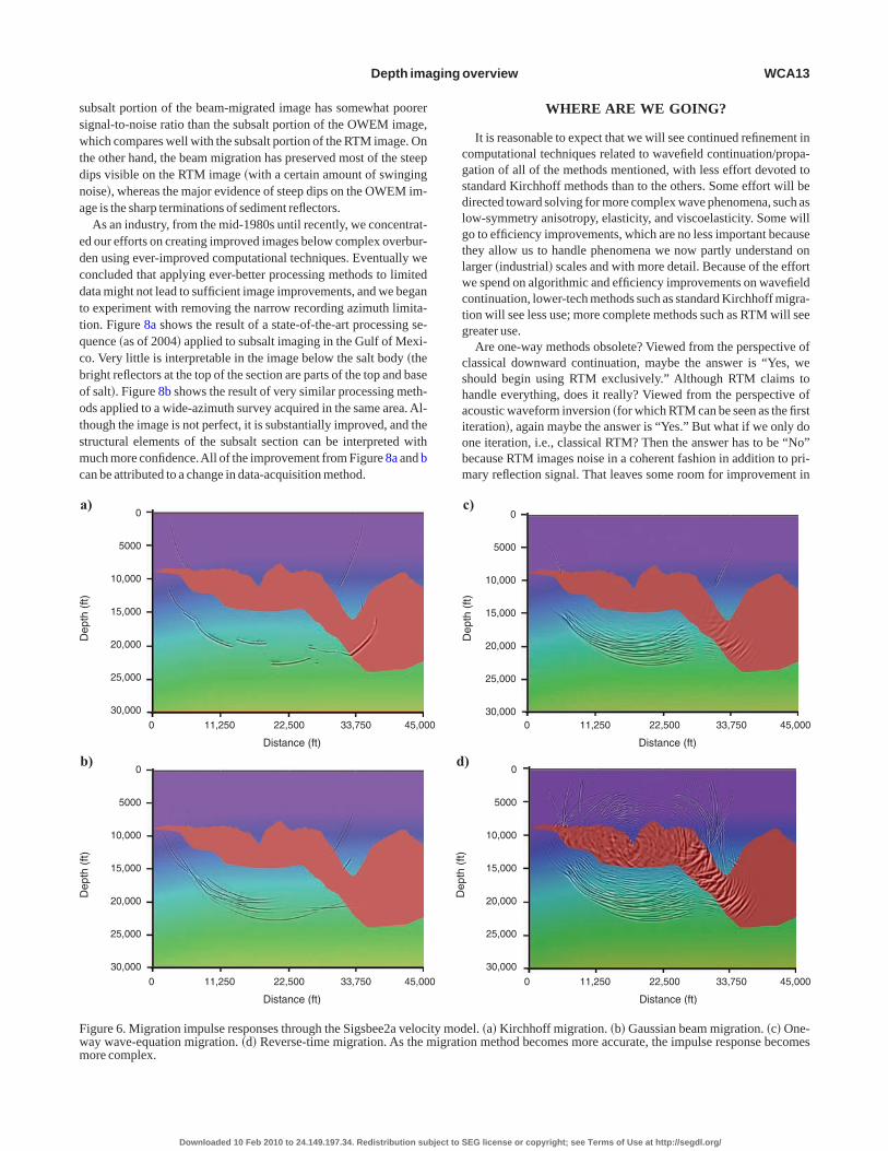
ous methods in a complex structural setting, the Sigsbee2a saltodel �Paffenholz, 2001�.Figure 6 illustrates the migration opera-
ors on a single event at 6 s on a zero-offset input trace. The Kirch-off migration response �Figure 6a� shows discontinuities character-stic of single-arrival Kirchhoff migration. These discontinuitiesontribute considerable noise to the final image, which is the super-osition of migration responses from all events on all input traces.The Gaussian beam migration �Figure 6b� shows a much more
omplete response than the Kirchhoff migration, with a minimum ofiscontinuities. The multipathing capabilities of Gaussian beam mi-ration ensures that most, if not all, geometric �ray� arrivals will con-ribute to the image and that these contributions will tend to havemooth decay. However, a few of the migrated events show incorrectinematic behavior as they pass from sediments to salt. This is a con-equence of the fact that the central rays associated with the individ-al events �the beams� have limited ability to sense the velocitytructure that is near, but not actually on, the raypaths.
The OWEM and RTM images �Figure 6c and d� show much richeravefields than the ray-based images. The wave-equation methods
re not restricted to geometric events, and comparing the beam mi-ration response with the wave-equation migration responses on thisodel shows how much wave energy can be carried by nongeomet-
ic arrivals when the top of salt has typical complexity. In fact, theTM image is far more complex than the OWEM image, indicating
he amount of wavefield information not captured by the one-wayave equation. In addition to steep dips and turning waves, the RTM
mage contains significant amounts of interbed multiple energy andpward-scattered energy that are considered as noise in current pro-essing. So far, efforts to use RTM to take advantage of the extraavefield information have had limited success, but the informationrovides an opportunity for future RTM applications.Our second example compares the same migration methods on
he BP 2004 model data set �Brandsberg-Dahl and Billette, 2005�.his complicated data set poses challenges for all imaging methods.
t contains two salt bodies, one with very rough top of salt and thether with extremely steep dips. Because the rough top of salt on theeft salt body can cause chaotic ray behavior, subsalt imaging isroblematic for ray-based migrations. Likewise, the steep dips causeroblems for dip-limited OWEM. Of the four images in Figure 7, theirchhoff �Figure 7a� is clearly the worst and the RTM �Figure 7d� is
clearly the best. The quality of the Gaussian beam �Figure 7b� andthe OWEM �Figure 7c� images lies between the two extremes. The
EG license or copyright; see Terms of Use at http://segdl.org/
sswtdna
edcdttqcbootsmc
cgsdlgtlwctg
cshaiobm
Fwm
Depth imaging overview WCA13
ubsalt portion of the beam-migrated image has somewhat poorerignal-to-noise ratio than the subsalt portion of the OWEM image,hich compares well with the subsalt portion of the RTM image. On
he other hand, the beam migration has preserved most of the steepips visible on the RTM image �with a certain amount of swingingoise�, whereas the major evidence of steep dips on the OWEM im-ge is the sharp terminations of sediment reflectors.
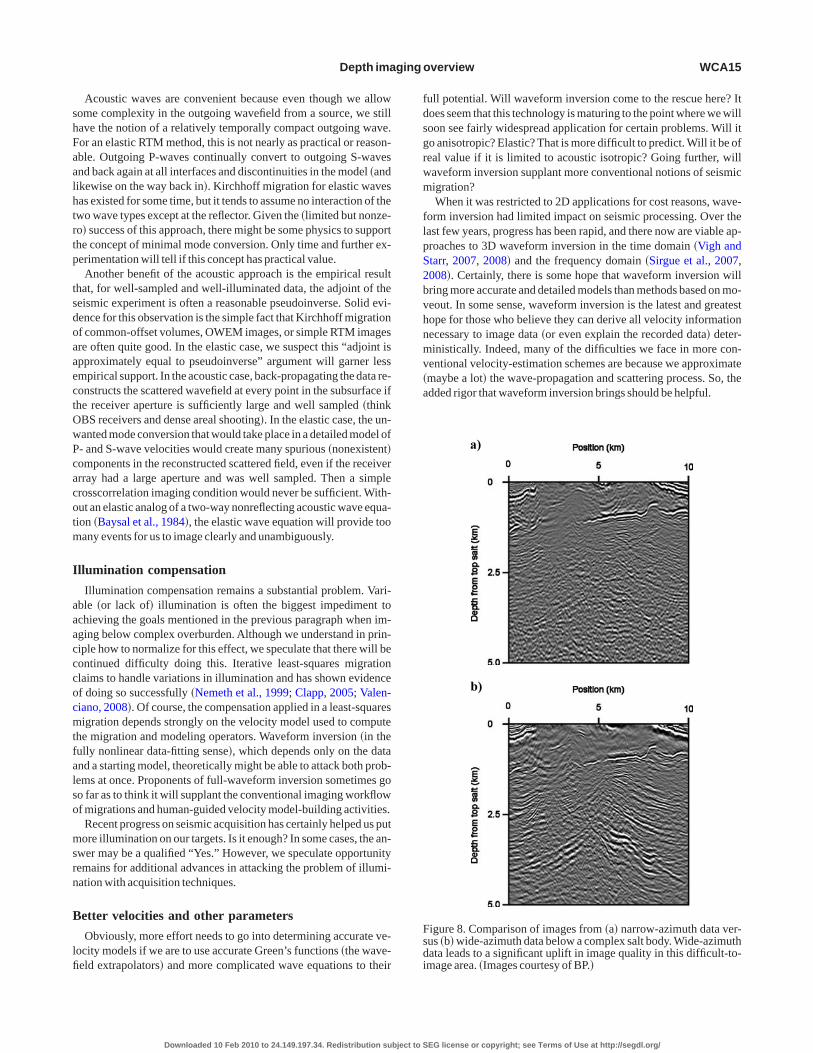
As an industry, from the mid-1980s until recently, we concentrat-d our efforts on creating improved images below complex overbur-en using ever-improved computational techniques. Eventually weoncluded that applying ever-better processing methods to limitedata might not lead to sufficient image improvements, and we begano experiment with removing the narrow recording azimuth limita-ion. Figure 8a shows the result of a state-of-the-art processing se-uence �as of 2004� applied to subsalt imaging in the Gulf of Mexi-o. Very little is interpretable in the image below the salt body �theright reflectors at the top of the section are parts of the top and basef salt�. Figure 8b shows the result of very similar processing meth-ds applied to a wide-azimuth survey acquired in the same area. Al-hough the image is not perfect, it is substantially improved, and thetructural elements of the subsalt section can be interpreted withuch more confidence.All of the improvement from Figure 8a and b
an be attributed to a change in data-acquisition method.
0
5000
10,000
15,000
20,000
25,000
30,000
0 11,250 22,500 33,750 45,00
Distance (ft)
Dep
th(f
t)
a)
0
5000
10,000
15,000
20,000
25,000
30,000
0 11,250 22,500 33,750 45,00
Distance (ft)
Dep
th(f
t)
b)
igure 6. Migration impulse responses through the Sigsbee2a velocay wave-equation migration. �d� Reverse-time migration. As the more complex.
Downloaded 10 Feb 2010 to 24.149.197.34. Redistribution subject to S
WHERE ARE WE GOING?
It is reasonable to expect that we will see continued refinement inomputational techniques related to wavefield continuation/propa-ation of all of the methods mentioned, with less effort devoted totandard Kirchhoff methods than to the others. Some effort will beirected toward solving for more complex wave phenomena, such asow-symmetry anisotropy, elasticity, and viscoelasticity. Some willo to efficiency improvements, which are no less important becausehey allow us to handle phenomena we now partly understand onarger �industrial� scales and with more detail. Because of the efforte spend on algorithmic and efficiency improvements on wavefield
ontinuation, lower-tech methods such as standard Kirchhoff migra-ion will see less use; more complete methods such as RTM will seereater use.Are one-way methods obsolete? Viewed from the perspective of
lassical downward continuation, maybe the answer is “Yes, wehould begin using RTM exclusively.” Although RTM claims toandle everything, does it really? Viewed from the perspective ofcoustic waveform inversion �for which RTM can be seen as the firstteration�, again maybe the answer is “Yes.” But what if we only done iteration, i.e., classical RTM? Then the answer has to be “No”ecause RTM images noise in a coherent fashion in addition to pri-ary reflection signal. That leaves some room for improvement in
0 11,250 22,500 33,750 45,000
Distance (ft)
0
5000
10,000
15,000
20,000
25,000
30,000
Dep
th(f
t)
c)
0
5000
10,000
15,000
20,000
25,000
30,000
0 11,250 22,500 33,750 45,000
Distance (ft)
Dep
th(f
t)
)
el. �a� Kirchhoff migration. �b� Gaussian beam migration. �c� One-on method becomes more accurate, the impulse response becomes
0
0
d
ity modigrati
EG license or copyright; see Terms of Use at http://segdl.org/

ooioncm�
�sRstipttvtsmc
be
B
mtpitgtettrwpcc
Fm
WCA14 Etgen et al.
ne-way thinking. Perhaps if we think of one-way methods in termsf one-way-outward �not downward� from the source and one-way-nward �not upward� toward the receivers �or the opposite dependingn which way we want the time axis to run�, there are still unhar-essed possibilities. Nichols �1994� shows in two dimensions how toreate one-way-outward Green’s functions with a wave-equationethod, and he applies it to computing sophisticated traveltimes
and amplitudes and phase factors� for migration.Expanding on the titled-coordinate system ideas, Sava and Fomel
2005�, Shragge �2008�, and Shragge and Shan �2008� propose moreophisticated coordinate systems for one-way extrapolation, callediemannian extrapolation. In principle, their approaches corre-pond well with a single backscattering model for the seismic reflec-ion experiment �upon which most of our understanding of imagings built�. They create steep dip images as RTM does, avoiding mostroblems of internal scattering that face RTM and avoiding the ques-ion of how to apportion energy in the image among multiple poten-ial reflection events when one abandons single scattering. So,iewed from the perspective of outward and inward wavefield con-inuation, one-way methods have useful advantages, and are not ob-olete. Therefore, modifying OWEM into outward-continuationethods might ensure usefulness of those methods for some time to
ome.
0
2000
4,000
6,000
8,000
10,000
11,500
0 10,912.5 21,825.0 32,737.5 43,750
Distance (ft)
Dep
th(f
t)
a)
b) 0
2000
4,000
6,000
8,000
10,000
11,500
0 10,912.5 21,825.0 32,737.5 43,750
Distance (ft)
Dep
th(f
t)
igure 7. Migrated images of the BP 2004 model data set. �a� Kirchhigration. �d� Reverse-time migration.
Downloaded 10 Feb 2010 to 24.149.197.34. Redistribution subject to S
The preceding assertions are relatively obvious, and progress iseing made in those directions. Next, we probe more speculative ar-as.
eyond structural imaging
The demand from the interpretation side of our business is toove beyond structural images and provide more stratigraphic de-
ail, and to move toward qualitative and eventually quantitativeroperties of rocks and pore fluids in a static imaging sense as well asn a dynamic, 4D sense. From the preceding section, we have most ofhe theoretical framework to do this, at least in the acoustic case. Thelaring omission might then seem to be the elastic �even viscoelas-ic?� case. Certainly, we see evidence of a solid, rather than fluid,arth in our data all of the time. Computationally, the elastic �aniso-ropic, viscoelastic, etc.� wave equations are much more demandinghan their acoustic counterparts, primarily because of the finer gridsequired to sample slow-moving shear waves. Is the correct path for-ard to implement our conventional acoustic ideas with an elasticropagator, e.g., elastic RTM? We discussed this issue earlier in theontext of TTI RTM for structural imaging; we revisit it here in theontext of elastic imaging.
)
)
0
2000
4,000
6,000
8,000
10,000
11,500
0 10,912.5 21,825.0 32,737.5 43,750.0
Distance (ft)
Dep
th(f
t)
0
2000
4,000
6,000
8,000
10,000
11,500
0 10,912.5 21,825.0 32,737.5 43,750.0
Distance (ft)
Dep
th(f
t)
gration. �b� Gaussian beam migration. �c� One-way wave-equation
.0
c
d
.0
off mi
EG license or copyright; see Terms of Use at http://segdl.org/
shFaalhtrtp
tsdoaaectOwPcacotm
I
aaacccocmtfalso
msrn
B
lfi
fdsgrwm
flpS2bvhnmv�a
Fsdi
Depth imaging overview WCA15
Acoustic waves are convenient because even though we allowome complexity in the outgoing wavefield from a source, we stillave the notion of a relatively temporally compact outgoing wave.or an elastic RTM method, this is not nearly as practical or reason-ble. Outgoing P-waves continually convert to outgoing S-wavesnd back again at all interfaces and discontinuities in the model �andikewise on the way back in�. Kirchhoff migration for elastic wavesas existed for some time, but it tends to assume no interaction of thewo wave types except at the reflector. Given the �limited but nonze-o� success of this approach, there might be some physics to supporthe concept of minimal mode conversion. Only time and further ex-erimentation will tell if this concept has practical value.Another benefit of the acoustic approach is the empirical result
hat, for well-sampled and well-illuminated data, the adjoint of theeismic experiment is often a reasonable pseudoinverse. Solid evi-ence for this observation is the simple fact that Kirchhoff migrationf common-offset volumes, OWEM images, or simple RTM imagesre often quite good. In the elastic case, we suspect this “adjoint ispproximately equal to pseudoinverse” argument will garner lessmpirical support. In the acoustic case, back-propagating the data re-onstructs the scattered wavefield at every point in the subsurface ifhe receiver aperture is sufficiently large and well sampled �thinkBS receivers and dense areal shooting�. In the elastic case, the un-anted mode conversion that would take place in a detailed model of- and S-wave velocities would create many spurious �nonexistent�omponents in the reconstructed scattered field, even if the receiverrray had a large aperture and was well sampled. Then a simplerosscorrelation imaging condition would never be sufficient. With-ut an elastic analog of a two-way nonreflecting acoustic wave equa-ion �Baysal et al., 1984�, the elastic wave equation will provide tooany events for us to image clearly and unambiguously.
llumination compensation
Illumination compensation remains a substantial problem. Vari-ble �or lack of� illumination is often the biggest impediment tochieving the goals mentioned in the previous paragraph when im-ging below complex overburden. Although we understand in prin-iple how to normalize for this effect, we speculate that there will beontinued difficulty doing this. Iterative least-squares migrationlaims to handle variations in illumination and has shown evidencef doing so successfully �Nemeth et al., 1999; Clapp, 2005; Valen-iano, 2008�. Of course, the compensation applied in a least-squaresigration depends strongly on the velocity model used to compute
he migration and modeling operators. Waveform inversion �in theully nonlinear data-fitting sense�, which depends only on the datand a starting model, theoretically might be able to attack both prob-ems at once. Proponents of full-waveform inversion sometimes goo far as to think it will supplant the conventional imaging workflowf migrations and human-guided velocity model-building activities.Recent progress on seismic acquisition has certainly helped us putore illumination on our targets. Is it enough? In some cases, the an-
wer may be a qualified “Yes.” However, we speculate opportunityemains for additional advances in attacking the problem of illumi-ation with acquisition techniques.
etter velocities and other parameters
Obviously, more effort needs to go into determining accurate ve-ocity models if we are to use accurate Green’s functions �the wave-eld extrapolators� and more complicated wave equations to their
Downloaded 10 Feb 2010 to 24.149.197.34. Redistribution subject to S
ull potential. Will waveform inversion come to the rescue here? Itoes seem that this technology is maturing to the point where we willoon see fairly widespread application for certain problems. Will ito anisotropic? Elastic? That is more difficult to predict. Will it be ofeal value if it is limited to acoustic isotropic? Going further, willaveform inversion supplant more conventional notions of seismicigration?When it was restricted to 2D applications for cost reasons, wave-
orm inversion had limited impact on seismic processing. Over theast few years, progress has been rapid, and there now are viable ap-roaches to 3D waveform inversion in the time domain �Vigh andtarr, 2007, 2008� and the frequency domain �Sirgue et al., 2007,008�. Certainly, there is some hope that waveform inversion willring more accurate and detailed models than methods based on mo-eout. In some sense, waveform inversion is the latest and greatestope for those who believe they can derive all velocity informationecessary to image data �or even explain the recorded data� deter-inistically. Indeed, many of the difficulties we face in more con-
entional velocity-estimation schemes are because we approximatemaybe a lot� the wave-propagation and scattering process. So, thedded rigor that waveform inversion brings should be helpful.
a)
b)
igure 8. Comparison of images from �a� narrow-azimuth data ver-us �b� wide-azimuth data below a complex salt body. Wide-azimuthata leads to a significant uplift in image quality in this difficult-to-mage area. �Images courtesy of BP.�
EG license or copyright; see Terms of Use at http://segdl.org/
iflh
tniflrnag�flpmb
lsaddeckt
W
uhwcwqsttfi
smmmtqtmcalmt
ttf
cvbttftppajo
ui
A
B
B
—
B
—
B
B
B
B
B
B
C
C
—
—
C
d
E
—
WCA16 Etgen et al.
Admittedly, though, we still are unsure how to describe waveformnversion in terms familiar to standard seismic processing. Does itocus primarily on diving waves? Does it also make long-wave-ength updates based on reflected data? Presumably, it does both; butow much of each, and how do we control it? Should we even try?What about a marriage of wave propagation with more conven-
ional velocity estimation techniques? Strictly kinematic gather flat-ess is a concept that has served us well over the years and has earnedts keep even in relatively complex situations. Going beyond gatheratness, wave-equation migration velocity analysis methods thately on image focusing �Sava and Biondi, 2004� seem to combine theecessary components: kinematics handled by wave propagationnd data attributes such as image focusing that are familiar from mi-ration. Intermediate approaches. i.e., differential semblanceSymes and Carazzone, 1991�, also bridge the gap between gatheratness and waveform inversion. As outgrowths of conventionalrocessing, these last two approaches should improve velocity esti-ation beyond what we can accomplish with purely kinematic, ray-
ased approaches.However, problems such as velocity determination below salt,
imited as they are by experimental geometry and critical angle is-ues for surface data, may not be amenable to waveform inversion orny other method that tries to match the data or match some attributeerived from the kinematics of the data such as gather flatness. Whato we do then? Certain technologies claim the ability to make imag-s at least partly independent of knowledge of the velocity. Will theyome to our rescue? There is also good old-fashioned geologicnowledge: Will basin modeling and computational geology comeo our rescue?
ill we ever get there?
Will the computer replace the interpreter? In our opinion, this isnlikely. Full �whatever that means� waveform inversion certainlyas that as an implicit goal. However, too many obstacles stand in theay. Despite all of the advances in data acquisition, we will never
ollect enough data. Even if we could populate the earth’s surfaceith sources and receivers, Green’s Second Theorem, which re-uires surrounding a target with sources and receivers, says that istill not enough data. This is related, but not entirely equivalent, tohe fact we do not sample the subsurface uniformly or regularly �inhe mathematical sense� to deal with illumination variability and de-ciency.
CONCLUSIONS
We have attempted to summarize the current state of the art ineismic depth imaging and, to a lesser degree, various forms of seis-ic inversion, and we have speculated on directions our subjectight take in the future. Comparing our initial statement, “The ulti-ate and perhaps unattainable goal of seismic imaging is to replace
he art of interpretation with a computational process that rendersuantitatively accurate models of the subsurface,” with our specula-ions, we must conclude with cautious pessimism. Our imagingethods are fairly successful in the narrow, familiar sense that we
an often produce drillable images of the earth’s subsurface withcoustic techniques applied to reflection data from an elastic or ane-astic earth. Far less often do the methods contribute to velocity esti-ation that ensures the drill bit will hit its target. Less often still do
hey produce useful amplitudes for detailed stratigraphic or ampli-
Downloaded 10 Feb 2010 to 24.149.197.34. Redistribution subject to S
ude analysis. We have pointed out why, in some settings, the veloci-y and amplitude problems might elude solution for the foreseeableuture.
On the other hand, we have made a certain amount of progress inombining seismic imaging with techniques such as waveform in-ersion, to the point of reducing the structural uncertainty of targetselow most complex overburden. We also have improved the ampli-ude behavior of our imaging algorithms in general. So it is certainhat we are moving toward automated, quantitative imaging, but it isar from certain how rapidly we are moving in that direction. Be-ween the alternative outcomes of �1� continuing incremental im-rovements in reducing structural uncertainty and estimating rockroperties and �2� dramatic improvements in quantitative imagingnd velocity estimation with minimal human intervention, we con-ecture a middle path of incremental improvements punctuated byccasional, isolated, spectacular success.
ACKNOWLEDGMENTS
We thank James Sun and Sheng Xu for providing some of the fig-res used and for many useful discussions. We thank BP and Freder-c Billette for permission to use the BPmodel data set.
REFERENCES
lkhalifah, T., 2000, An acoustic wave equation for anisotropic media: Geo-physics, 65, 1239–1250.
ale, R., S. Gray, and M. G. Kirtland-Grech, 2007, TTI wave-equation mi-gration: 77th Annual International Meeting, SEG, Expanded Abstracts,2295–2299.
aysal, E., D. D. Kosloff, and J. W. C. Sherwood, 1983, Reverse time migra-tion: Geophysics, 48, 1514–1524.—–, 1984, A two-way nonreflecting wave equation: Geophysics, 49,132–141.
erkhout, A. J., 1979, Steep dip finite-difference migration: Geophysics, 27,196–213.—–, 2008, Changing the mindset in seismic data acquisition: The LeadingEdge, 27, 924–938.
eylkin, G., 1985, Imaging of discontinuities in the inverse scattering prob-lem by inversion of a generalized Radon transform: Journal of Mathemati-cal Physics, 26, 99–108.
iondi, B., 2001, Kirchhoff imaging beyond aliasing: Geophysics, 66,654–666.
leistein, N., 1987, On the imaging of reflectors in the earth: Geophysics, 52,931–942.
leistein, N., J. K. Cohen, and J. W. Stockwell, 2001, Mathematics of multi-dimensional seismic inversion: Springer, NewYork.
randsberg-Dahl, S., 2001, Imaging-inversion and migration velocity analy-sis in the scattering angle/azimuth domain: Ph.D. dissertation, ColoradoSchool of Mines.
randsberg-Dahl, S., and F. Billette, 2005, The 2004 BPvelocity benchmark:67th Conference & Technical Exhibition, EAGE, Extended Abstracts,B035–B035.
hen, J., and H. Liu, 2006, Two kinds of separable approximations for theone-way wave operator: Geophysics, 71, no. 1, T1–T5.
laerbout, J., 1970, Coarse-grid calculations of waves in inhomogeneousmedia with application to delineation of complicated seismic structure:Geophysics, 35, 407–418.—–, 1971, Toward a unified theory of reflector mapping: Geophysics, 36,467–481.—–, 1985, Imaging the earth’s interior: Blackwell Scientific PublicationsInc.
lapp, M., 2005, Imaging under salt: Illumination compensation by regular-ized inversion: Ph.D. dissertation, Stanford University.
eBruin, C. G. M., C. P. A. Wapenaar, and A. J. Berkhout, 1990, Angle-de-pendent reflectivity by means of prestack migration: Geophysics, 55,1223–1234.
tgen, J., 1986, High-order finite-difference reverse time migration with thetwo-way non-reflecting wave equation: Stanford Exploration Project Re-port, 48, 133–146.—–, 1994, Stability of explicit depth extrapolation through laterally vary-ing media: 64thAnnual International Meeting, SEG, ExpandedAbstracts,1266–1269.
EG license or copyright; see Terms of Use at http://segdl.org/
E
F
F
G
G
H
—
H
H
H
H
H
K
K
L
L
L
M
M
M
M
N
N
N
O
P
P
R
R
—
R
S
S
—
S
S
S
S
S
—
S
S
S
S
S
TT
V
V
—
W
—
W
X
X
Z
Z
Z
Z
Z
Z
Z
Z
Depth imaging overview WCA17
tgen, J., and S. Brandsberg-Dahl, 2002, Waves beams and rays, an illumi-nating if incoherent view of the future of migration: 72nd Annual Interna-tional Meeting, SEG, The RoadAhead presentation.
letcher, R., X. Du, and P. J. Fowler, 2008, A new pseudo-acoustic waveequation for TI media: 78th Annual International Meeting, SEG, Expand-edAbstracts, 2082–2086.
rench, W. S., 1975, Computer migration of oblique seismic reflection pro-files: Geophysics, 40, 961–980.
azdag, J., 1978, Wave equation migration with the phase-shift method:Geophysics, 43, 1342–1351.
azdag, J., and P. Sguazzero, 1984, Migration of seismic data by phase shiftplus interpolation: Geophysics, 49, 124–139.
ale, D., 1991a, Stable explicit depth extrapolation of seismic wavefields:Geophysics, 56, 1770–1777.—–, 1991b, 3-D depth migration by McClellen transformations: Geophys-ics, 56, 1778–1785.
ale, D., N. R. Hill, and J. Stefani, 1992, Imaging salt with turning seismicwaves: Geophysics, 57, 51–59.
igginbotham, J., Y. Shin, and D. V. Sukup, 1985, Directional depth migra-tion: Geophysics, 50, 1784–1789.
ill, N. R., 2001, Prestack Gaussian-beam depth migration: Geophysics, 66,1240–1250.
olberg, O., 1988, Toward optimum one-way wave propagation: Geophysi-cal Prospecting, 36, 99–114.
uang, L.-J., and R.-S. Wu, 1996, Prestack depth migration with acousticscreen propagators: 66th Annual International Meeting, SEG, ExpandedAbstracts, 415–418.
oren, Z., I. Ravve, E. Ragoza, A. Bartana, and D. Kosloff, 2008, Full-azi-muth angle domain imaging: 78th Annual International Meeting, SEG,ExpandedAbstracts, 2221–2225.
osloff, D., and E. Baysal, 1982, Forward modeling by a Fourier method:Geophysics, 47, 1402–1412.
ee, M., and S. Suh, 1985, Optimization of one-way equation: Geophysics,50, 1634–1637.
e Rousseau, J. H., and M. V. de Hoop, 2001, Modeling and imaging with thescalar generalized-screen algorithms in isotropic media: Geophysics, 66,1551–1568.
i, Z., 1991, Compensating finite-difference errors in 3-D migration andmodeling: Geophysics, 56, 1650–1660.a, Z., 1982, Steep dip finite difference migration: Oil Geophysical Pros-pecting, 1, 6–15 �in Chinese�.argrave, G., and R. Ferguson, 1999, Wavefield extrapolation by nonsta-tionary phase shift: Geophysics, 64, 1067–1078.cMechan, G. A., 1983, Migration by extrapolation of time-dependentboundary values: Geophysical Prospecting, 31, 413–420.uijs, R., J. O. A. Robertsson, and K. Holliger, 2007, Prestack depth migra-tion of primary and surface-related multiple reflections: Part 1 — Imaging:Geophysics, 72, no. 2, S59-S69.
emeth, T., C. Wu, and G. T. Schuster, 1999, Least-squares migration of in-complete reflection data: Geophysics, 64, 208–221.
ichols, D., 1994, Imaging complex structures using band-limited Green’sfunctions: Ph.D. dissertation, Stanford University.
olte, B., I. Ahmed, P. Mahob, D. Shepherd, R. Faerber, and J. Howie, 2008,Application of one-way wave-equation migration in tilted coordinates tosalt-model building at Atlantis: 78th Annual International Meeting, SEG,ExpandedAbstracts, 2316–2320.
perto, M. S., S. Xu, and G. Lambaré, 2000, Can we quantitatively imagecomplex structures with rays?: Geophysics, 65, 1223–1238.
affenholz, J., 2001, Sigsbee2 synthetic subsalt data set: Image quality asfunction of migration algorithm and velocity model error: 71st Annual In-ternational Meeting, SEG, Workshop W-5.
rucha, M., B. L. Biondi, and W. W. Symes, 1999, Angle-domain common-image gathers by wave-equation migration: 69th Annual InternationalMeeting, SEG, ExpandedAbstracts, 824–827.
ietveld, W. E. A., and A. J. Berkhout, 1994, Prestack depth migration bymeans of controlled illumination: Geophysics, 59, 801–809.
istow, D., and T. Ruhl, 1994, Fourier finite-difference migration: Geophys-ics, 59, 1882–1893.—–, 1997, 3-D implicit finite-difference migration by multiway splitting:Geophysics, 62, 554–567.
omero, L. A., D. C. Ghiglia, C. C. Ober, and S. A. Morton, 2000, Phase en-coding of shot records in prestack migration: Geophysics, 65, 426–436.
ava, P., and B. Biondi, 2004, Wave equation migration velocity analysis —I.Theory: Geophysical Prospecting, 52, 593–606.
ava, P., and S. Fomel, 2003, Angle-domain common-image gathers by
Downloaded 10 Feb 2010 to 24.149.197.34. Redistribution subject to S
wavefield continuation methods: Geophysics, 67, 883–889.—–, 2005, Riemannian wavefield extrapolation: Geophysics, 70, no. 3,T45–T56.
chneider, W. A., 1978, Integral formulation for migration in two and threedimensions: Geophysics, 43, 49–76.
han, G., and B. Biondi, 2008, Plane-wave migration in tilted coordinates:Geophysics, 73, no. 5, S185–S194.
hragge, J., 2008, Riemannian wavefield extrapolation: Nonorthogonal co-ordinate systems: Geophysics, 73, no. 2, T11–T21.
hragge, J., and G. Shan, 2008, Prestack wave-equation depth migration inelliptical coordinates: Geophysics, 73, no. 5, S169–S175.
irgue, L., J. Etgen, and U. Albertin, 2007, 3D full-waveform inversion:Wide-versus narrow-azimuth acquisitions: 77th Annual InternationalMeeting, SEG, ExpandedAbstracts, 1760–1764.—–, 2008, 3D frequency domain waveform inversion using time domainfinite difference methods: 70th Conference & Technical Exhibition,EAGE. ExtendedAbstracts, F022.
oubaras, R., 1996, Explicit 3-D migration using equiripple polynomial ex-pansion and Laplacian synthesis: Geophysics, 61, 1386–1393.
toffa, P. L., J. T. Fokkema, R. M. de Luna Freire, and W. P. Kessinger, 1990,Split-step Fourier migration: Geophysics, 55, 410–421.
tork, C., and J. Kapoor, 2006, On delayed-shot 3D depth migration: Geo-physics, 71, no. 5, X25–X30.
un, Y., F. Qin, S. Checkles, and J. P. Leveille, 2000, 3-D prestack Kirchhoffbeam migration for depth imaging: Geophysics, 65, 1592–1603.
ymes, W. W., and J. J. Carazzone, 1991, Velocity inversion by differentialsemblance optimization: Geophysics, 56, 654–663.
homsen, L., 1986, Weak elastic anisotropy: Geophysics, 51, 1954–1966.svankin, I., 2001, Seismic signatures and analysis of reflection data in an-isotropic media: Elsevier Science Publ. Co., Inc.
alenciano, A., 2008, Imaging by wave equation inversion: Ph.D. disserta-tion, Stanford University.
igh, D., and E. W. Starr, 2007, 3D prestack plane-wave full-waveform in-version: 77th Annual International Meeting, SEG, Expanded Abstracts,1830–1834.—–, 2008, Comparisons for waveform inversion, time domain or frequen-cy domain: 78thAnnual International Meeting, SEG, ExpandedAbstracts,1890–1894.hitmore, N. D., 1983, Iterative depth migration by backward time propaga-tion: 53rd Annual International Meeting, SEG, Expanded Abstracts, 382–385.—–, 1995, An imaging hierarchy for common angle plane-wave seismo-grams: Ph.D. dissertation, The University of Tulsa.u, R.-S., M. Q. Luo, S. C. Chen, and X. B. Xie, 2004, Acquisition aperturecorrection in angle-domain and true-amplitude imaging for wave-equa-tion migration: 74th Annual International Meeting, SEG, Expanded Ab-stracts, 1008–1011.
u, S., H. Chauris, G. Lambare, and M. Noble, 2001, Common-angle migra-tion:Astrategy for imaging complex media: Geophysics, 66, 1877–1894.
u, S., and T. Huang, 2007, Migration artifacts and velocity analysis: 77thAnnual International Meeting, SEG, ExpandedAbstracts, 3019–3023.
hang, G., S. Zhang, Y. Wang, and C. Liu, 1988, A new algorithm for finite-difference migration of steep dips: Geophysics, 53, 167–175.
hang, H., and Y. Zhang, 2008, Reverse time migration in 3D heterogen-eous TTI media: 78th Annual International Meeting, SEG, ExpandedAbstracts, 2196–2200.
hang, Y., C. Notfors, and Y. Xie, 2003, Stable x-k wavefield extrapolation ina v�x,y,z� medium: 73rd Annual International Meeting, SEG, ExpandedAbstracts, 1083–1086.
hang, Y., and J. Sun, 2009, Practical issues of reverse time migration: True-amplitude gathers, noise removal and harmonic-source encoding: FirstBreak, 27, no. 1, 53–60.
hang, Y., S. Xu, N. Bleistein, and G. Zhang, 2007, True amplitude angle do-main common image gathers from one-way wave equation migrations:Geophysics, 72, no. 1, S49–58.
hang, Y., S. Xu, and G. Zhang, 2006, Imaging complex salt bodies withturning-wave one-way wave equation: 76th Annual International Meet-ing, SEG, ExpandedAbstracts, 2323–2327.
hang, Y., G. Zhang, and N. Bleistein, 2005, Theory of true amplitude one-way wave equations and true amplitude common-shot migration: Geo-physics, 70, no. 4, E1–10.
hou, H., G. Zhang, and R. Bloor, 2006, An anisotropic acoustic wave equa-tion for modeling and migration in 2D TTI media: 76th Annual Interna-tional Meeting, SEG, ExpandedAbstracts, 194–198.
EG license or copyright; see Terms of Use at http://segdl.org/