an investigation into the use of r12, r12 mixtures in air conditioners
TRANSCRIPT
An investigation into the use of R12, R13 mixtures in air conditioners
P. L. Ohar and S. M. Bin Gadhi
Recherches sur I'utilisation de m61anges de R1 2 et de R1 3 dans les condition- neurs d'air
On pr#sente une appreciation de r utilisation de m#langes de frigorig#nes ~ la suite de recherches sur la performance d'un conditionneur d'air 'type fen#tre'. On a choisi ce syst#me parce que les variations de temperature sont reladvement grandes. On d#crit les importants r~sultats de r#tude ainsi que des propositions pour r#duire la consommation cr #nergie et obtenir une performance optimale.
An appraisal of the usa of mixed refrigerants is presented fol lowing an investigation on the performance of a window sir conditioner. This system was chosen because the tempera-
ture changes are comparatively large. Th.e important results of the study and proposals to reduce power consumption and achieve opt imum performance are described.
A number of papers 1-s have appeared during the last two decades recommending the use of refrigerant mixtures especially in applications involving large changes in the temperature of the coolant. Besides an improvement in the thermodynamic performance as a result of the non-isothermal nature of the refrigeration 4. a number of other advantages, like the attainment of very low temperatures with single stage machines 1'2. reduction in winding tempera- ture 6, etc., have also been claimed. However, so far, no systematic study of the implications of using refrigerant mixtures seems to have been done. While almost all of the experimental studies conducted hitherto have been heuristic in nature, theoretical investigations are almost nonexistent due to lack of data on the thermodynamic properties of mixed refrigerants. The only attempt at theoretical prediction of refrigeration system performance with mixed refrigerants has been done by Agrawal and Arora 5 using the thermodynamic data obtained by Agrawal 7. The basis of calculation is the assumption of equal values of the log-mean temperature difference (LMTD) in both condenser and evap- orator, for pure R22, R12 and for the mixtures of R12 and R1 3. This, however, does not give a correct appraisal of the system performance since keeping LMTD constant implies constancy of heat transfer in the evaporator and the condenser which therefore does not match with the changed performance of the compressor with mixed refrigerants. Further, using mixed refrigerants in cold storage applications (the cases analysed in reference 5) does not seem to be really necessary, since the temperature change of air in cold diffusers has to be kept very small to minimize its dehumidification.
The authors are in the Department of Mechanical Engineering. Indian Institute of Technology, Delhi. India. Paper received 29 January 1980
Volume 3 Number 3 May 1980
It was therefore felt that there is a need for carrying out a proper appraisal of the use of mixed refrig- erants. The system selected for investigation is a window air-conditioner, since the temperature changes of air, both in the condenser and in the evaporator, are fairly large (10-15°C). The paper presents some of the important results of this investigation, the details of which can be found in reference 8. An independent, theoretical and experimental investigation into use of R12+ R21 mixtures for air-conditioning duties, carried out by Burr and Hasalden 11, has been recently brought to authors' notice. They found that by using cost optimized designs, a 20 to 30% reduction in total operating cost could be achieved.
Data co l lect ion and analysis
As the first step towards analysis, the complete technical data for a 1 t, window air-conditioner marketed by a prominent Indian manufacturer was obtained. This included detailed design of the condenser and the evaporator coils, the inside and outside design conditions and its total cooling capacity. The design details of the compressor were obtained from the compressor manufacturer.
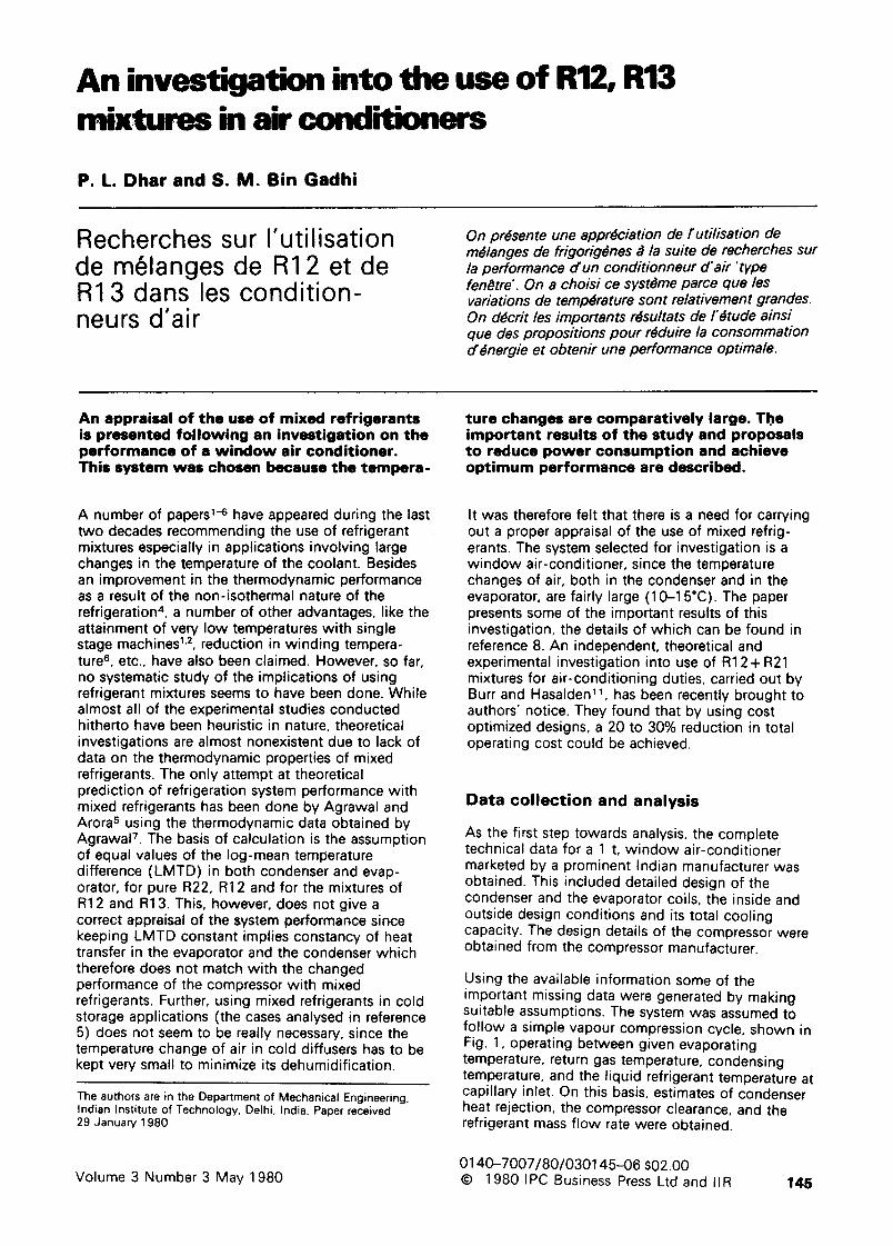
Using the available information some of the important missing data were generated by making suitable assumptions. The system was assumed to follow a simple vapour compression cycle, shown in Fig. 1, operating between given evaporating temperature, return gas temperature, condensing temperature, and the liquid refrigerant temperature at capillary inlet. On this basis, estimates of condenser heat rejection, the compressor clearance, and the refrigerant mass flow rate were obtained.
0140-7007/80/030145--06 $02.00 © 1980 IPC Business Press Ltd and IIR 145
Having obtained the magnitude of the heat transfer in the condenser, the value of the overall heat transfer coefficient in this crossflow heat exchanger is determined by the usual approach 9. Due to the lack of information about the sensible heat factor, and for the sake of simplicity, it is assumed that all the heat transfer in evaporator is 'sensible'. The evaporator is then analysed in the same manner as the condenser and an appropriate value of the 'effective', overall heat transfer coefficient has been determined.
Estimates of the U value for these two 'heat exchangers' have also been obtained from their known physical, design parameters and air f low rates fol lowing the procedures of Kays and London ~°. The U values obtained from graphical procedure of reference 10 differ only very slightly from those calculated using performance data. For the sake of consistency, however, the latter values have been used in further calculations.
System simulation with refrigerant mixtures
Simulation of the air-condit ioner wi th mixed refrigerants has been done fol lowing the graphical approach outlined by Stoecker 9. The refrigeration capacities obtained from the compressor, the evaporator and the condenser considered separately, are calculated at various possible combinations of evaporator and condenser pressures. The performance curves for each of these components are then plotted and suitably super- imposed to get the final operating conditions.
Q.
t3=46.10C
/ 4'
162.8
a 2 ~
I o
7 8 7 150.13 154.4
114.87
E~hell~, keel I~m-I
Fig. 1 A simple vapour compression cycle operating between a given evaporation temperature, return gas temperature, condensing temperature and liquid refrigerant temperature at the capillary inlet
Fig. 1 Cycle de compression de vapeur simple fonctionnant entre une temp#rature cr #vaporation, une temperature de gaz /'aspiration. une temp#rature de condensation et une temperature du frigong#ne liquide donn#es ~ /'entr#e des cap/I/aires
The heat transfer calculations fgr the evaporator and condenser are done using the effectiveness concept lo. Bqth of these are treated as crossflow heat exchangers with air as the unmixed fluid and the refrigerant mixture as the mixed fluid. Suitable assumptions have been made, to determine the effectiveness of these heat exchangers when operating with mixed refrigerants. Thus, the overall heat transfer coefficient values for both the evaporator and the condenser are taken as being the same as with pure R22. This is not really as serious an assumption, as it may appear prima facie, be- cause the U values for these equipment are primarily governed by the air side heat transfer coefficient.
The second assumption is regarding the calculation of the heat capacity ratio, CR, which is infinite for the case of pure refrigerants. Here, this is computed as:
C R = Cmixed/Cunmixed = Cref/Cai r
with Cref=m~efCpe
The effective specific heat, Cp~, is defined as:
Cpe= qo/ A T
where AT is the temperature range over which the heat transfer qo (boil ing or condensation) takes place with mixed refrigerants, Knowing the U value, the heat capacities of the two fluids and the surface area, the calculation of the heat exchanger effectiveness, and hence the heat transfer, is quite straight-forward 1°. While the heat transfer in the evaporator is directly the refrigeration capacity obtainable, the condenser heat transfer, Q~ond, is converted to equivalent refrigeration capacity, Qko, as:
Qko = (QoonJqk)qo
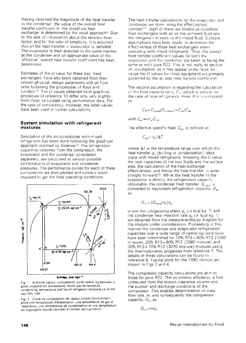
where the refrigerating effectqo (in kcal kg ~) and the condenser heat rejection rate qk (in kcal kg ~) are obtained from the pressure-enthalpy diagram for the mixture under consideration. Proceeding in this manner the condenser and evaporator refrigeration capacities over a wide range of operating condit ions have been determined for 10% R13+90% R12 (1090 mixture), 20% R13+80% R12 (2080 mixture) and 30% R13+70% R12 (3070 mixture) mixtures using the thermodynamic properties from reference 7. The details of these calculations can be found in reference 8. Typical plots for the 1 090 mixture are shown in Figs 2 and 4.
The compressor capacity calculations are akin to those for pure R22. The volumetric efficiency is first computed from the known clearance volume and the suction and discharge condit ions of the compressor. This enables determination of mass f low rate, m, and consequently the compressor capacity, Qoo as:
Oco=mqo
146 Revue lnternationale du Froid
Pk =18
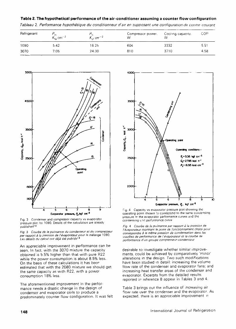
dependent on the condensing pressure which determines the initial temperature of the evaporating refrigerant. Consequently the operating point has to be suitably chosen so as to correspond to the same condensing pressure in the evaporator performance curves and the condensing unit performance curve (Fig. 4).
300( 16
"o
8
point
15
2000
. . . . 4 5 6 7 8
Evoporotor pressure, Po, kgf cm -2
Fig. 2 A typical condenser capacity vs evaporator pressure curve for a 1 090 refrigerant mixture 7.8
Fig. 2 Courbe d'une puissance de condenseur typique par rapport ~ /a pression de I'#vaporateur pour un m#lange de frigorig#nes 10907,8
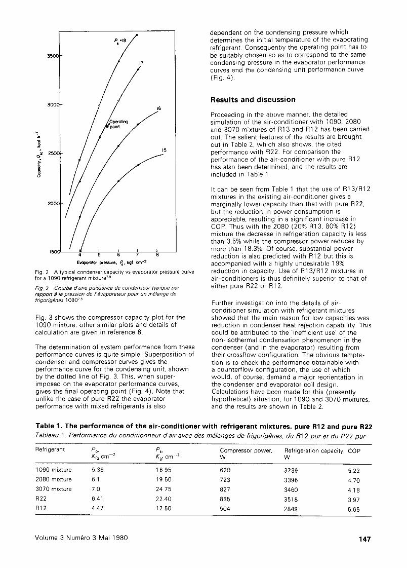
Fig. 3 shows the compressor capacity plot for the 1090 mixture; other similar plots and details of calculation are given in reference 8.
The determination of system performance from these performance curves is quite simple. Superposition of condenser and comlSressor curves gives the performance curve for the condensing unit, shown by the dotted line of Fig. 3. This, when super- imposed on the evaporator performance curves, gives the final operating point (Fig. 4). Note that unlike the case of pure R22 the evaporator performance with mixed refrigerants is also
Results and discussion
Proceeding in the above manner, the detailed simulation of the air-condit ioner wi th 1090, 2080 and 3070 mixtures of R13 and R12 has been carried out. The salient features of the results are brought out in Table 2, which also shows, the cited performance with R22. For comparison the performance of the air-condit ioner with pure R12 has also been determined, and the results are included in Table 1.
It can be seen from Table 1 that the use of R13/R12 mixtures in the existing air-condit ioner gives a marginally lower capacity than that with pure R22, but the reduction in power consumption is appreciable, resulting in a significant increase in COP. Thus with the 2080 (20% R13,80% R12) mixture the decrease in refrigeration capacity is less than 3.5% while the compressor power reduces by more than 1 8.3%. Of course, substantial power reduction is also predicted with R12 but this is accompanied with a highly undesirable 1 9% reduction in capacity. Use of R13/R12 mixtures in air-conditioners is thus definitely superior to that of either pure R22 or R12.
Further investigation into the details of air- condit ioner simulation with refrigerant mixtures showed that the main reason for low capacities was reduction in condenser heat rejection capability. This could be attributed to the "inefficient use' of the non-isothermal condensation phenomenon in the condenser (and in the evaporator) resulting from their crossftow configuration. The obvious tempta- tion is to check the performance obtainable wi th a counterf low configuration, the use of which would, of course, demand a major reorientation in the condenser and evaporator coil design. Calculations have been made for this (presently hypothetical) situation, for 1090 and 3070 mixtures, and the results are shown in Table 2.
Table 1. The performance of the air-conditioner with refrigerant mixtures, pure R12 and pure R22 Tableau 1. Performance du cond/tionneur d'air avec des m#langes de frigorig~nes, du R1 2 pur et du R22 pur
Refrigerant Po, Pk, Compressor power, Refrigeration capacity, COP Zfg cm -2 Kgf cm -2 W W
1090 mixture 5.36 1 6.95 620 3239 5.22
2080 mixture 6.1 19.50 723 3396 4.70
3070 mixture 7.0 24.75 827 3460 4.1 8
R22 6.41 22.40 885 351 8 3.97
R12 4.47 12.50 504 2849 5.65
Volume 3 Num~ro 3 Mai 1980 147
T a b l e 2 . T h e h y p o t h e t i c a l p e r f o r m a n c e o f t h e a i r - c o n d i t i o n e r a s s u m i n g a c o u n t e r f l o w c o n f i g u r a t i o n
Tableau 2. Pe r fo rmance h y p o t h ~ t i q u e du c o n d i t i o n n e u r d 'a i r en s u p p o s a n t une con f i gu ra t i on de c o n t r e - c o u r a n t
Refrigerant Po. Pk, Compressor power, Cooling capacity. COP Kfg cm -2 Kgf cm 2 W W
1090 5.42 1 6.25 604 3332 5.51
3070 7.05 24.00 81 0 3710 4.58
I . c
8
/ /
Pk = t8 I
t7
| 16 /
15
Ope~oting point
I I I I | I
4 5 6 7 8 9 E~porotor ixessure, Po,IRf cm -2
Fig. 3 Condenser and compressor capacity vs evaporator pressure plot for 1090. Details of the calculation are already published 7.8
Fig. 3 Courbe de la puJssance du condenseur et du compresseur par rapport ~ la pression de/'#vaporateur pour/e m#/ange 1090. Les ddtai/s du calcul ont d~/~ #t~ pub/i#s 7'8
An appreciable improvement in performance can be seen. In fact, w i th the 3070 mixture the capacity obta ined is 5.5% higher than that w i th pure R22 whi le the power consumpt ion is about 8.5% less. On the basis of these calculations it has been estimated that wi th the 2080 mixture we should get the same capacity as w i th R22, wi th a power consumpt ion 1 8% less.
The aforementioned improvement in the perfor- mance needs a drastic change in the design of condenser and evaporator coils to produce a predominately counter f low configurat ion. It was felt
i J¢
J I
4
Operoting conditions:-
= 536 ~ crn -~' Oe= 2785 I~ol h -I Pk = 16.95 kcol cm "=
I I Y I I 5 6 7 8 9
Evoporotor pressure, Pa, kgf cm -=
Fig. 4 Capacity vs evaporator pressure plot showing the operating point chosen to correspond to the same condensing pressure in the evaporator performance curves and the condensing unit performance curve
Fig 4 Courbe de/a puissance par rapport ~ /a presslon de f #vaporateur montrant le point de foncdonnement choisi pour correspondre # la m#me pression de condensation dans les courbes de performance de/'#vaporateur et la courbe de performance d'un groupe compresseur-condenseur
IO
desirable to investigate whether similar improve- ments, could be achieved by comparatively 'minor' alterations in the design. Two such modif icat ions have been studied in detail: increasing the volume f low rate of the condenser and evaporator fans; and increasing heat transfer areas of the condenser and evaporator. Excerpts from the detailed results reported in reference 8 appear in Tables 3 and 4.
Table 3 brings out the inf luence of increasing air f low rate over the condenser and the evaporator. As expected, there is an appreciable improvement in
148 International Journal of Refrigeration
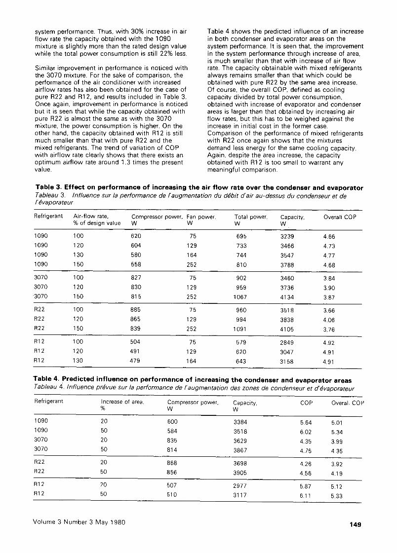
system performance. Thus, with 30% increase in air f low rate the capacity obtained with the 1090 mixture is slightly more than the rated design value while the total power consumption is still 22% less.
Similar improvement in performance is noticed with the 3070 mixture. For the sake of comparison, the performance of the air conditioner with increased airflow rates has also been obtained for the case of pure R22 and R12, and results included in Table 3. Once again, improvement in performance is noticed but it is seen that while the capacity obtained with pure R22 is almost the same as with the 3070 mixture, the power consumption is higher. On the other hand, the capacity obtained with R1 2 is still much smaller than that with pure R22 and the mixed refrigerants. The trend of variation of COP with airflow rate clearly shows that there exists an optimum airflow rate around 1.3 times the present value.
Table 4 shows the predicted influence of an increase in both condenser and evaporator areas on the system performance. It is seen that, the improvement in the system performance through increase of area, is much smaller than that with increase of air flow rate. The capacity obtainable with mixed refrigerants always remains smaller than that which could be obtained with pure R22 by the same area increase. Of course, the overall COP, defined as cooling capacity divided by total power consumption, obtained with increase of evaporator and condenser areas is larger than that obtained by increasing air f low rates, but this has to be weighed against the increase in initial cost in the former case. Comparison of the performance of mixed refrigerants with R22 once again shows that the mixtures demand less energy for the same cooling capacity. Again, despite the area increase, the capacity obtained with R12 is too small to warrant any meaningful comparison.
Table 3. Effect on per formance of increasing the air f low rate over the condenser and evaporator Tableau 3. Influence sur la performance de/'augmentation du d#bit of air au-dessus du condenseur et de I'#vaporateur
Refrigerant Air-flow r a t e , Compressor power, Fan power, Total power, Capacity, Overall COP % of design Value W W W W
1090 100 620 75 695 3239 4,66
1090 120 604 129 733 3466 4.73
1090 130 580 164 744 3547 4.77
1090 150 558 252 810 3788 4.68
3070 100 827 75 902 3460 3.84
3070 120 830 129 959 3736 3.90
3070 150 815 252 1067 4134 3.87
R22 100 885 75 960 3518 3.66
R22 120 865 129 994 3838 4.06
R22 150 839 252 1091 4105 3.76
R12 100 504 75 579 2849 4.92
R12 120 491 129 620 3047 4.91
R12 130 479 164 643 3158 4.91
Table 4. Predicted inf luence on per formance of increasing the condenser and evaporator areas Tableau 4. influence pr#vue sur /a performance de/'augmentation des zones de condenseur et d'#vaporateur
Refrigerant Increase of a r e a , Compressor power, Capacity, COP Overall COP % W W
1090 20 600 3384 5.64 5.01
1090 50 584 3518 6.02 5.34
3070 20 835 3629 4.35 3.99
3070 50 814 3867 4.75 4.35
R22 20 868 3698 4.26 3.92
R22 50 856 3905 4.56 4.19
R12 20 507 2977 5.87 5.12
R1 2 50 510 3117 6.11 5.33
Volume 3 Number 3 May 1980 149
C o n c l u s i o n
On the basis of the detailed simulation of air- condit ioners using mixtures of R13 and R12, the results of which have been presented above, the fo l lowing main conclusions can be drawn: it should be possible to effect a considerable reduction in power consumption of w indow air-condit ioners by a judicious switchover to R13, R12 mixtures; to achieve opt imum performance with these refrigerant mixtures in existing air-condit ioners, the volume f low rate of the condenser and evaporator fans should be suitably enhanced; and substantial improvement in performance wi th mixed refrigerants can be achieved by redesigning the evaporator and the condenser for a 'counterf low' configuration.
There is defini tely a great need for further in- vestigation into the use of mixed refrigerants. Thus the condensation and boil ing phenomena wi th mixed refrigerants should be studied to find out actual refrigerant side heat transfer coefficients to enable more realistic appraisals of the system performance. The simulation models could obviously be further refined and made more realistic especially by taking into consideration the effect of moisture condensation on evaporator coils. From the equipment design point of view, it is essential to investigate ful ly the effect of combining various proposed methods for maximum improvement in performance. Some other practical considerations which need investigation are: the influence of differing rates of diffusion of R12 and R13 through a 'leakage point' on the mixture composit ion and thence the system performance and the miscibi l i ty of compressor oil wi th these mixtures, etc Of course,
the final proof of the uti l i ty of these m~xtures would need long term performance testing of a properly designed prototype with mixed refrigerants
R e f e r e n c e s
1 Haselden, G. G., Klimek, K. The use of mixed refrigerants Proc Institute of Refrigeration (London) (1957-58)
2 Tachaikovski, V. F., Kuznetsov, B. P. Utilization of refrigerant mixtures in refrigerating compression machines XI Int Congress of Refrigeration. 1 (1963) 693-696
3 Tachaikovski, V. F., Arora, C. P. Using mixtures of refrigerants Journa/ of Institution of Engineers" (India) XLIV (Jan 1964) 128-134
4 Arora, C. P. Power savings and low temperatures m refrigerating machines using mixed refrigerants. PhD Thesis, Indian Institute of Technology, Delhi (1966)
5 Agrawal, R. S., Arora, C. P. Theoretical prediction of vapour compression refrigeration system performance using R12, R13 mixtures Proc Fourth National Symp on Refrigeration and Air conditioning liT, Delhi (1975) t75- 183
6 Bhalla, B. K. Investigation into the blending of Freon 12 in Freon 22 for use in window type air-conditioner M Tech Thesis, Mech Eng Dept, Indian Institute of Technology, Delhi (1971)
7 Agrawal, R. S. Vapour-liquid equilibrium and thermody namic properties of flurocarbon mixtures using Redlich Kwong equation of state, PhD Thesis, Indian Institute of Technology, Delhi (1975)
8 Gadhi, S. M. Bin Investigation of the use of R12 and R13 mixtures in air-conditioners. M Tech Thesis, Mech Eng Dept, Indian Institute of Technology, Delhi (1979)
9 Stoecker, W. F. Refrigeration and Air-conditioning McGraw Hill Book Co, New Yor k (1958)
10 Kays, W. M., London, A. L. Compact Heat Exchangers McGraw Hill Book Co, New York (1955)
11 Burr, P. S., Haselden, G. G. A non-isothermal mixed refrigerant cycle for air-conditioning duties Proc of the Institute of Refrigeration (UK) 71 (1974-5) 18-22
1,50 Revue Internationale du Froid