an introduction to symmetrical components, system modeling and · pdf file ·...
TRANSCRIPT
Symmetrical Components March 11, 2013
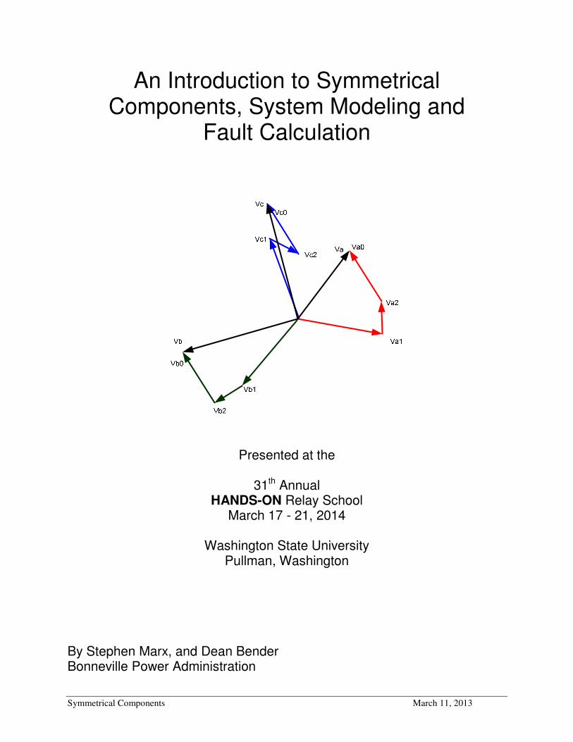
An Introduction to Symmetrical Components, System Modeling and
Fault Calculation
Presented at the
31th Annual HANDS-ON Relay School
March 17 - 21, 2014
Washington State University Pullman, Washington
By Stephen Marx, and Dean Bender Bonneville Power Administration


Symmetrical Components Page 1
Introduction
The electrical power system normally operates in a balanced three-phase sinusoidal steady-state
mode. However, there are certain situations that can cause unbalanced operations. The most
severe of these would be a fault or short circuit. Examples may include a tree in contact with a
conductor, a lightning strike, or downed power line.
In 1918, Dr. C. L. Fortescue wrote a paper entitled “Method of Symmetrical Coordinates
Applied to the Solution of Polyphase Networks.” In the paper Dr. Fortescue described how
arbitrary unbalanced 3-phase voltages (or currents) could be transformed into 3 sets of balanced
3-phase components, Fig I.1. He called these components “symmetrical components.” In the
paper it is shown that unbalanced problems can be solved by the resolution of the currents and
voltages into certain symmetrical relations.
C
B
C
B
Fig I.1
By the method of symmetrical coordinates, a set of unbalanced voltages (or currents) may be
resolved into systems of balanced voltages (or currents) equal in number to the number of phases
involved. The symmetrical component method reduces the complexity in solving for electrical
quantities during power system disturbances. These sequence components are known as
positive, negative and zero-sequence components, Fig I.2
Fig I.2

Symmetrical Components Page 2
The purpose of this paper is to explain symmetrical components and review complex algebra in
order to manipulate the components. Knowledge of symmetrical components is important in
performing mathematical calculations and understanding system faults. It is also valuable in
analyzing faults and how they apply to relay operations.
1. Complex Numbers
The method of symmetrical components uses the commonly used mathematical solutions applied
in ordinary alternating current problems. A working knowledge of the fundamentals of algebra
of complex numbers is essential. Consequently this subject will be reviewed first.
Any complex number, such as jba + , may be represented by a single point p, plotted on a
Cartesian coordinates, in which a is the abscissa on the x axis of real quantities and b the
ordinate on the y axis of imaginary quantities. This is illustrated in Fig. 1.1
θ
Fig. 1.1
Referring to Fig. 1.1, let r represent the length of the line connecting the point p to the origin
and θ the angle measured from the x-axis to the line r. It can be observed that
θcos⋅= ra (1.1)
θsin⋅= rb (1.2)
2. Properties of Phasors
A vector is a mathematical quantity that has both a magnitude and direction. Many quantities in
the power industry are vector quantities. The term phasor is used within the steady state
alternating linear system. It is used to avoid confusion with spatial vectors: the angular position
of the phasor represents position in time, not space. In this document, phasors will be used to
document various ac voltages, currents and impedances.
A phasor quantity or phasor, provides information about not only the magnitude but also the
direction or angle of the quantity. When using a compass and giving directions to a house, from
a given location, a distance and direction must be provided. For example one could say that a
house is 10 miles at an angle of 75 degrees (rotated in a clockwise direction from North) from
where I am standing. Just as we don’t say the other house is -10 miles away, the magnitude of

Symmetrical Components Page 3
the phasor is always a positive, or rather the absolute value of the “length of the phasor.”
Therefore giving directions in the opposite direction, one could say that a second house is 10
miles at an angle of 255 degrees. The quantity could be a potential, current, watts, etc.
Phasors are written in polar form as
θ∠= YY (2.1)
θθ sincos YjY += (2.2)
where Y is the phasor, Y is the amplitude, magnitude or absolute value and θ is the phase angle
or argument. Polar numbers are written with the magnitude followed by the ∠ symbol to
indicate angle, followed by the phase angle expressed in degrees. For example oZ 90110∠= .
This would be read as 110 at an angle of 90 degrees. The rectangular form is easily produced by
applying Eq. (2.2)
The phasor can be represented graphically as we have demonstrated in Fig. 1.1, with the real
components coinciding with the x axis.
When multiplying two phasors it is best to have the phasor written in the polar form. The
magnitudes are multiplied together and the phase angles are added together. Division, which is
the inverse of multiplication, can be accomplished in a similar manner. In division the
magnitudes are divided and the phase angle in the denominator is subtracted from the phase
angle in the numerator.
Example 2.1
Multiply BA ⋅ where oA 355∠= and o
B 453∠= .
Solution
( ) ( )ooooBA 453535453355 +∠⋅=∠⋅∠=⋅ o8015∠=
Example 2.2
Solve D
C where o
C 3515∠= and oD 503∠= .
Solution
( )oo
o
o
D
C5035
3
15
503
3515−∠
=
∠
∠=
o155 −∠=

Symmetrical Components Page 4
3. The j and a operator
Recall the operator j. In polar form, oj 901∠= . Multiplying by j has the effect of rotating a
phasor o90 without affecting the magnitude.
Table 3.1 - Properties of the vector j
0.00.11 j+= oj 901∠=
118012 −=∠= oj
jj o −=∠= 27013 oj 901 −∠=−
1−=j
Example 3.1
Compute jR where oR 6010∠= .
Solution
)6010(901 oojR ∠∠= o15010∠=
Notice that multiplication by the j operator rotated the Phasor R by o90 , but did not change the
magnitude. Refer to Fig. 3.1
R
(a) R
jR
R
(b) Rj
Fig. 3.1. j effects
Symmetrical Components Page 5
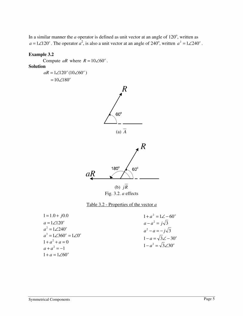
In a similar manner the a operator is defined as unit vector at an angle of 120o, written as
oa 1201∠= . The operator a
2, is also a unit vector at an angle of 240
o, written o
a 24012 ∠= .
Example 3.2
Compute aR where oR 6010∠= .
Solution
)6010(1201 ooaR ∠∠= o18010∠=
R
(a) A
aR
R
(b) Rj
Fig. 3.2. a effects
Table 3.2 - Properties of the vector a
0.00.11 j+= o
a 1201∠= o
a 24012 ∠= oo
a 0136013 ∠=∠=
01 2 =++ aa
12 −=+ aa o
a 6011 ∠=+
oa 6011 2 −∠=+
32 jaa =−
32 jaa −=−
oa 3031 −∠=−
oa 3031 2 ∠=−

Symmetrical Components Page 6
4. The three-phase System and the relationship of the 3
In a Wye connected system the voltage measured from line to line equals the square root
of three, 3 , times the voltage from line to neutral. See Fig. 4.1 and Eq. (4.1). The line
current equals the phase current, see Eq. (4.2)
Fig. 4.1
LNLL VV 3= (4.1)
Φ= IIL (4.2)
In a Delta connected system the voltage measured from line to line equals the phase
voltage. See Fig. 4.2 and Eq. (4.3). The line current will equal the square root of three,
3 , times the phase current, see Eq. (4.4)
VLL
IΦIΦ
IL
Fig. 4.2
Φ= VVLL (4.3)
Φ= IIL 3 (4.4)

Symmetrical Components Page 7
The power equation, for a three phase system, is
LLLIVS 3= (4.5a)
ψcos3 LLLIVP = (4.5b)
ψsin3 LLLIVQ = (4.5c)
where S is the apparent power or complex power in volt-amperes (VA). P is the real
power in Watts (W, kW, MW). Q is the reactive power in VARS (Vars, kVars, MVars).
5. The per-unit System 5.1 Introduction
In many engineering situations it is useful to scale, or normalize, dimensioned quantities.
This is commonly done in power system analysis. The standard method used is referred
to as the per-unit system. Historically, this was done to simplify numerical calculations
that were made by hand. Although this advantage is eliminated by the calculator, other
advantages remain.
• Device parameters tend to fall into a relatively narrow range, making erroneous
values conspicuous.
• Using this method all quantities are expressed as ratios of some base value or
values.
• The per-unit equivalent impedance of any transformer is the same when referred
to either the primary or the secondary side.
• The per-unit impedance of a transformer in a three-phase system is the same
regardless of the type of winding connections (wye-delta, delta-wye, wye-wye, or
delta-delta).
• The per-unit method is independent of voltage changes and phase shifts through
transformers where the base voltages in the winding are proportional to the
number of turns in the windings.
• Manufactures usually specify the impedance of equipment in per-unit or percent
on the base of its nameplate rating of power (usually kVA) and voltage (V or kV).
The per-unit system is simply a scaling method. The basic per-unit scaling equation is
valuebase
valueactualunitper
_
_=− (5.1)
The base value always has the same units as the actual value, forcing the per-unit value to
be dimensionless. The base value is always a real number, whereas the actual value may
be complex. The subscript pu will indicate a per-unit value. The subscript base will

Symmetrical Components Page 8
indicate a base value, and no subscript will indicate an actual value such as Amperes,
Ohms, or Volts.
Per-unit quantities are similar to percent quantities. The ratio in percent is 100 times the
ratio in per-unit. For example, a voltage of 70kV on a base of 100kV would be 70% of
the base voltage. This is equal to 100 times the per unit value of 0.7 derived above.
The first step in using per-unit is to select the base(s) for the system.
Sbase = power base, in VA. Although in principle Sbase may be selected arbitrarily, in
practice it is typically chosen to be 100 MVA.
Vbase = voltage base in V. Although in principle Vbase is also arbitrary, in practice Vbase is
equal to the nominal line-to-line voltage. The term nominal means the value at which the
system was designed to operate under normal balanced conditions.
From Eq. (4.5a) it follows that the base power equation for a three-phase system is:
basebasebase IVS 33 =Φ (5.2)
Solving for current:
base
baseV
SI base
3
3Φ=
Because S3Φbase can be written as kVA or MVA and voltage is usually expressed in kilo-
volts, or kV, current can be written as:
ampereskV
kVAI
base
basebase
3= (5.3)
Solving for base impedance:
base
base
base
basebase
S
V
I
VZ
2
==
ohmskVA
xkVZ
base
basebase
10002
= (5.4a)
or
ohmsMVA
kVZ
base
basebase
2
= (5.4b)
Symmetrical Components Page 9
Given the base values, and the actual values: IZV = , then dividing by the base we are
able to calculate the pu values
pupupu
basebasebase
ZIVZI
IZ
V
V=⇒=
After the base values have been selected or calculated, then the per-unit impedance
values for system components can be calculated using Eq. (5.4b)
)()(
2Ω⋅
=
Ω= Z
kV
MVA
Z
ZZ
base
base
base
pu (5.5a)
or
)(1000 2
Ω⋅
⋅= Z
kV
kVAZ
base
basepu (5.5b)
It is also a common practice to express per-unit values as percentages (i.e. 1 pu = 100%).
(Transformer impedances are typically given in % at the transformer MVA rating.) The
conversion is simple
100
_ valuepercentunitper =−
Then Eq. (5.5a) can be written as
( ) ( )22 10
100%
base
base
base
base
kV
ZkVA
kV
ZMVAZ
Ω=
Ω⋅= (5.6)
It is frequently necessary, particularly for impedance values, to convert from one (old)
base to another (new) base. The conversion is accomplished by two successive
application of Eq. (5.1), producing:
=
new
base
old
baseold
pu
new
puZ
ZZZ
Substituting for old
baseZ and new
baseZ and re-arranging the new impedance in per-unit equals:
2
=
new
base
old
base
old
base
new
baseold
pu
new
pukV
kV
kVA
kVAZZ (5.7)
In most cases the turns ratio of the transformer is equivalent to the system voltages, and
the equipment rated voltages are the same as the system voltages. This means that the
voltage-squared ratio is unity. Then Eq. (5.7) reduces to
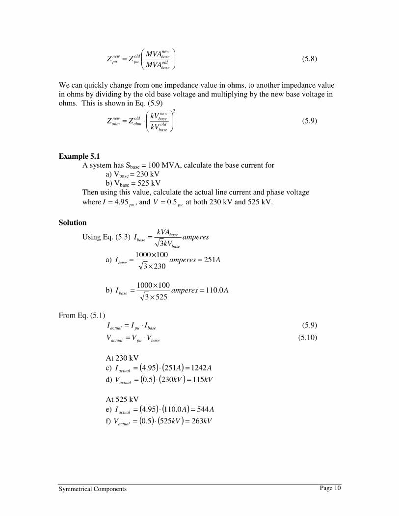
Symmetrical Components Page 10
=
old
base
new
baseold
pu
new
puMVA
MVAZZ (5.8)
We can quickly change from one impedance value in ohms, to another impedance value
in ohms by dividing by the old base voltage and multiplying by the new base voltage in
ohms. This is shown in Eq. (5.9) 2
⋅=
old
base
new
baseold
ohm
new
ohmkV
kVZZ (5.9)
Example 5.1
A system has Sbase = 100 MVA, calculate the base current for
a) Vbase = 230 kV
b) Vbase = 525 kV
Then using this value, calculate the actual line current and phase voltage
where puI 95.4= , and puV 5.0= at both 230 kV and 525 kV.
Solution
Using Eq. (5.3) ampereskV
kVAI
base
basebase
3=
a) AamperesIbase 2512303
1001000=
×
×=
b) AamperesI base 0.1105253
1001000=
×
×=
From Eq. (5.1)
basepuactual III ⋅= (5.9)
basepuactual VVV ⋅= (5.10)
At 230 kV
c) ( ) ( ) AAI actual 124225195.4 =⋅=
d) ( ) ( ) kVkVVactual 1152305.0 =⋅=
At 525 kV
e) ( ) ( ) AAI actual 5440.11095.4 =⋅=
f) ( ) ( ) kVkVVactual 2635255.0 =⋅=

Symmetrical Components Page 11
Example 5.2
A 900 MVA 525/241.5 autotransformer has a nameplate impedance of 10.14%
a) Determine the impedance in ohms, referenced to the 525 kV side.
b) Determine the impedance in ohms, referenced to the 241.5 kV side
Solution
First convert from % to pu.
1014.0100
%==
ZZpu
Arranging Eq. (5.5a) and solving for Zactual gives
base
basepu
MVA
kVZZ
2
)( =Ω ; therefore
a) 900
5251014.0
2
525 ×=kVZ
Ω= 05.31
b) 900
5.2411014.0
2
5.241 ×=kVZ
Ω= 57.6
A check can be made to see if the high-side impedance to the low-side impedance
equals the turns ratio squared.
726.457.6
05.31= 726.4
5.241
5252
=
5.1 Application of per-unit
Appling this to relay settings, a practical example can be shown in calculation of the
settings for a relay on a transmission line. For distance relays a common setting for zone
1 is 85% of the line impedance. Zone 2 should be set not less than 125% of the line, with
care to not over reach the zone 1 of the next line section. If this does then zone 2 will
need to be coordinated with the next line section zone 2.
Referring to Fig. 5.1 the line impedance for the 161 kV line is oZ 813.59 ∠= ohms.
Using the above criteria of 85% for zone 1 and 125 % for zone 2 the relays would be set
at
For zone 1
)8131.59%(85)(1
oZ ∠=Ω oZ 814.50)(1 ∠=Ω

Symmetrical Components Page 12
For zone 2
)8131.59%(125)(2
oZ ∠=Ω oZ 811.74)(2 ∠=Ω
Fig 5.1
For the relays on the 115 kV side of the transformer, the impedance of the transformer
needs to be calculated. From example 5.2 we see that
200
11506796.0
2
115 ×=kVZ
Ω= 494.4
Next the line impedance needs referenced to the 115 kV side of the transformer. Using
equation 5.9 2
⋅=
old
base
new
baseold
ohm
new
ohmkV
kVZZ (5.9)
Substituting, the line impedance equals
ohmsZ kV
ohm 3.30161
1153.59
2
115 =
⋅=
Adding this to the transformer, the impedance setting for the relays on the 115 kV side of
the transformer is oZ 828.34 ∠=
Using the same criteria for zone 1 and zone 2 reach.
For zone 1
)828.34%(85)(1
oZ ∠=Ω oZ 816.29)(1 ∠=Ω
For zone 2
)818.34%(125)(2
oZ ∠=Ω oZ 815.43)(2 ∠=Ω
Given these values, one can easily see that by ignoring the base values of the voltages the
relay settings would not be adequate. For example if the 161 kV settings were applied to
the 115 kV relays, zone 1 would over reach the remote terminal. Conversely, if the 115
Ia
xx
21
Ia
xx
21
161 kV
115 kV
|Z| = 59.3 @ 81o ohms
Z% = 6.796
200MVA 161/115kV
|Z| = 34.8 @ 81o ohms

Symmetrical Components Page 13
kV settings were applied to the 161 kV relays zone 2 would not reach past the remote
terminal and would thus not protect the full line.
Ia
xx
21
Ia
xx
21
161 kV
115 kV|Z| = 59.3 @ 81o ohms
Z% = 6.796
200MVA 161/115kV
|Z| = 34.8 @ 82o ohms
Z1 = 50.4 @ 81o
ohms
Z2 = 74.1 @ 81o
ohms
Z1 = 29.6 @ 82o
ohms
Z2 = 43.5 @ 82o
ohms
Fig. 5.2
5.2 Calculating actual values from per-unit
In the following sections we will discuss symmetrical faults. The analysis of the faults
uses the per-unit. A impedance and voltage of the system is express in per-unit. Then
the fault current and fault voltage is solved and that value will be given in per unit. Next
we need to convert from per-unit to actual amps and volts by using the base values.
Using the above equations it is easy to prove the following equations.
The MVA for a three phase fault is given as
PUZ
MVAMVA
Fault
BaseFault = (5.10)
Or
PUZMVA
Fault
Fault
100= for a 100 MVABase (5.11 a)
PUZ
II
Fault
Base
CurrentFault =_ (5.12)
Or
( ) ( )BaseFault
CurrentFaultkVPUZ
I3
000,100_
⋅= (5.12 a)
5.3 Converting per-unit
Before using the per-unit impedance of a transformer from a manufacture nameplate you
must first convert it to a per-unit value of your system. Typically the three-phase power
base of 100MVA is used. This is done by first converting the per unit impedance to an
actual impedance (in ohms) at 525kV and then converting the actual impedance to a per-
unit impedance on the new base. Repeat, this time converting the per unit impedance to

Symmetrical Components Page 14
an actual impedance (in ohms) at 241.5kV and then converting the actual impedance to a
per-unit impedance on the new base.
In the problem 3 at the end of this document, the transformer nameplate data is for a ratio
of 525/241.5kV or 2.174, whereas BPA’s ASPEN model uses nominal voltages of 525kV
and 230kV for a ratio of 2.283. Because BPA used a transformer ratio in ASPEN model
that was different than the transformer nameplate values, we have a discrepancy in the
per-unit impedance values that we obtained. The problem arises because when a
transformer is applied to the BPA system the transformer tap used will often be different
than the one used in the nameplate calculations.
What is the correct way to convert the per-unit impedance to the BPA base?
Because the actual impedance of the transformer will vary when different taps are used,
the most accurate way to model the impedance would be to actually measure the
impedance with the transformer on the tap that will normally be used on the BPA system.
This impedance would then be converted to a per-unit value on the BPA model base.
Since this isn’t normally possible, a close approximation can be made by assuming that
the per-unit impedance given on the nameplate will remain the same for the different tap
positions of the transformer. Find the transformer tap position that most closely matches
the ratio of the ASPEN model (2.283 for a 525/230kV transformer), then convert the
nameplate per-unit impedance to an actual value based on either the high- or low-side
voltage given for that tap position. This actual impedance is then converted to a per-unit
value on the BPA model base, using the high-side BPA voltage base if the high-side
voltage was used for the conversion to actual impedance, or using the low-side BPA
voltage base if the low-side voltage was used for the conversion to actual impedance.
See problem 4.
6. Sequence Networks
Refer to the basic three-phase system as shown in Fig. 6.1. There are four conductors to
be considered: a, b, c and neutral n.
anV bnV cnV
cI
bI
nI
aI
Fig. 6.1

Symmetrical Components Page 15
The phase voltages, pV , for the balanced 3Φ case with a phase sequence abc are
o
paan VVV 0∠== (6.1a)
o
pbbn VVV 120−∠== (6.1b)
o
ppccn VVVV 2401200 −∠=+∠== (6.1c)
The phase-phase voltages, LLV , are written as
o
LLbaab VVVV 30∠=−= (6.2a) o
LLcbbc VVVV 90−∠=−= (6.2b)
o
LLacca VVVV 150∠=−= (6.2c)
Equation (6.1) and (6.2) can be shown in phasor form in Fig. 6.2.
Ψ
Ψ
Ψ
Fig. 6.2
There are two balanced configurations of impedance connections within a power system.
For the wye case, as shown in Fig. 4.1, and with an impedance connection of Ψ∠Z , the
current can be calculated as
ψ−∠== o
Y
P
Y
aZ
V
Z
VI 0 (6.3)
Where Ψ is between o90− and + o90 . For Ψ greater than zero degrees the load would be
inductive ( aI lags aV ). For ψ less than zero degrees the load would be capacitive
( aI leads aV ).
Symmetrical Components Page 16
The phase currents in the balanced three-phase case are
ψ−∠= o
pa II 0 (6.4a)
ψ−−∠= o
pb II 120 (6.4b)
ψ−−∠= o
pc II 240 (6.4c)
See Fig. 6.2. for the phasor representation of the currents.
7. Symmetrical Components Systems
The electrical power system operates in a balanced three-phase sinusoidal operation.
When a tree contacts a line, a lightning bolt strikes a conductor or two conductors swing
into each other we call this a fault, or a fault on the line. When this occurs the system
goes from a balanced condition to an unbalanced condition. In order to properly set the
protective relays, it is necessary to calculate currents and voltages in the system under
such unbalanced operating conditions.
In Dr. C. L. Fortescue’s paper he described how symmetrical components can transform
an unbalanced condition into symmetrical components, compute the system response by
straight forward circuit analysis on simple circuit models, and transform the results back
into original phase variables. When a short circuit fault occurs the result can be a set of
unbalanced voltages and currents. The theory of symmetrical components resolves any
set of unbalanced voltages or currents into three sets of symmetrical balanced phasors.
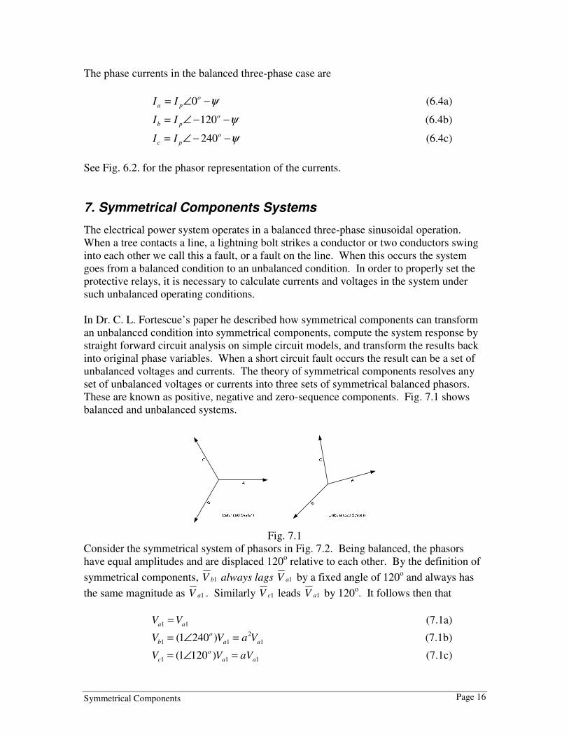
These are known as positive, negative and zero-sequence components. Fig. 7.1 shows
balanced and unbalanced systems.
B
Fig. 7.1
Consider the symmetrical system of phasors in Fig. 7.2. Being balanced, the phasors
have equal amplitudes and are displaced 120o relative to each other. By the definition of
symmetrical components, 1bV always lags 1aV by a fixed angle of 120o and always has
the same magnitude as 1aV . Similarly 1cV leads 1aV by 120o. It follows then that
11 aa VV = (7.1a)
1
2
11 )2401( aa
o
b VaVV =∠= (7.1b)
111 )1201( aa
o
c aVVV =∠= (7.1c)

Symmetrical Components Page 17
Where the subscript (1) designates the positive-sequence component. The system of
phasors is called positive-sequence because the order of the sequence of their maxima
occur abc.
Similarly, in the negative and zero-sequence components, we deduce
22 aa VV = (7.2a)
222 )1201( aa
o
b aVVV =∠= (7.2b)
2
2
22 )2401( aa
o
c VaVV =∠= (7.2c)
00 aa VV = (7.3a)
00 ab VV = (7.3b)
00 ac VV = (7.3c)
Where the subscript (2) designates the negative-sequence component and subscript (0)
designates zero-sequence components. For the negative-sequence phasors the order of
sequence of the maxima occur cba, which is opposite to that of the positive-sequence.
The maxima of the instantaneous values for zero-sequence occur simultaneously.
Fig.7.2
In all three systems of the symmetrical components, the subscripts denote the
components in the different phases. The total voltage of any phase is then equal to the
sum of the corresponding components of the different sequences in that phase. It is now
possible to write our symmetrical components in terms of three, namely, those referred to
the a phase (refer to section 3 for a refresher on the a operator).
210 aaaa VVVV ++= (7.4a)
210 bbbb VVVV ++= (7.4b)
210 cccc VVVV ++= (7.4c)

Symmetrical Components Page 18
We may further simplify the notation as follows; define
00 aVV = (7.5a)
11 aVV = (7.5b)
22 aVV = (7.5c)
Substituting their equivalent values
210 VVVVa ++= (7.6a)
21
2
0 aVVaVVb ++= (7.6b)
2
2
10 VaaVVVc ++= (7.6c)
These equations may be manipulated to solve for 0V , 1V , and 2V in terms of aV , bV , and
cV .
( )cba VVVV ++=3
10 (7.7a)
( )cba VaaVVV2
13
1++= (7.7b)
( )cba aVVaVV ++= 2
23
1 (7.7c)
It follows then that the phase currents are
210 IIIIa ++= (7.8a)
21
2
0 aIIaIIb ++= (7.8b)
2
2
10 IaaIIIc ++= (7.8c)
The sequence currents are given by
( )cba IIII ++=3
10 (7.9a)
( )cba IaaIII2
13
1++= (7.9b)
( )cba aIIaII ++= 2
23
1 (7.9c)
The unbalanced system is therefore defined in terms of three balanced systems. Eq. (7.6)
may be used to convert phase voltages (or currents) to symmetrical component voltages
(or currents) and vice versa [Eq. (7.7)].

Symmetrical Components Page 19
Example 7.1
Given o
aV 535∠= , o
bV 1647 −∠= , o
cV 1057∠= , find the symmetrical
components. The phase components are shown in the phasor form in Fig. 7.3
Va
Vb
Vc
Unbalanced condition
53o
105o
-164o
Fig. 7.3
Solution
Using Eq. (7.7a)
Solve for the zero-sequence component:
( )cbaa VVVV ++=3
10
( )ooo 105716475353
1∠+−∠+∠=
o1225.3 ∠=
From Eq. (7.3b) and (7.3c) o
bV 1225.30 ∠= o
cV 1225.30 ∠=
Solve for the positive-sequence component:
( )cbaa VaaVVV2
13
1++=
( ) ( )( )ooooo 10572401164712015353
1∠⋅∠+−∠⋅∠+∠=
o100.5 −∠=
From Eq. (7.1b) and (7.1c) o
bV 1300.51 −∠= o
cV 1100.51 ∠=
Solve for the negative-sequence component:
( )cbaa aVVaVV ++= 2
23
1

Symmetrical Components Page 20
( ) ( )( )ooooo 10571201164724015353
1∠⋅∠+−∠⋅∠+∠=
o929.1 ∠=
From Eq. (7.2b) and (7.2c) o
bV 1489.12 −∠= o
cV 289.12 −∠=
The sequence components can be shown in phasor form in Fig. 7.4.
Fig. 7.4
Using Eq. (7.6) the phase voltages can be reconstructed from the sequence components.
Example 7.2
Given oV 1225.30 ∠= , oV 100.51 −∠= , oV 929.12 ∠= , find the phase sequence
components. Shown in the phasor form in Fig. 7.4
Solution
Using Eq. (7.6)
Solve for the A-phase sequence component:
210 VVVVa ++= ooo 929.1100.51225.3 ∠+−∠+∠=
o530.5 ∠=
Solve for the B-phase sequence component:
21
2
0 aVVaVVb ++= ooo 1489.11300.51225.3 −∠+−∠+∠=
o1640.7 −∠=

Symmetrical Components Page 21
Solve for the C-phase sequence component:
2
2
10 VaaVVVc ++= ooo 289.11100.51225.3 −∠+∠+∠=
o1050.7 ∠=
This returns the original values given in Example 5.2.
This can be shown in phasor form in Fig. 7.5.
Vc2
Vc0
Vc1
Va2
Va1
Va0
Vb0
Vb2
Vb1
Va
Vb
Vc
Fig. 7.5
Notice in Fig. 7.5 that by adding up the phasors from Fig. 7.4, that the original phase, Fig.
7.3 quantities are reconstructed.
Understanding symmetrical components can aid us in trouble shooting problems. Some
relays measure positive sequence power. Modifying equation 7.7b for power, it follows
then that the positive sequence power is
( )cba PaaPPP2
13
1++= (7.10)
For a balanced system, at unity power factor the phase sequence power would shown in
phasor from in Fig 7.6

Symmetrical Components Page 22
Fig. 7.5
From equation 7.10, the positive sequence power equals, ( )cba PaaPPP2
13
1++= . Under
a balanced system this simplifies to aPP =1 .
Fig. 7.6
This is an approximation of the average of the A-phase, B-phase and C-phase power. Se
figure 7.6
Let’s assume that the B and C phase voltages were swapped. From a phasor diagram we
see that the B-phase power now leads A-phase by 120 degrees, and C-phase power lags
by 120 degrees. Figure 7.7
Fig. 7.7

Symmetrical Components Page 23
From equation 7.10, the positive sequence power equals, ( )cba PaaPPP2
13
1++= .
However, with the B-phase and C-phase voltage swapped, 01 =P .
Fig. 7.7
Figure 7.8 shows the phasor diagram
8. Balanced and Unbalanced Fault analysis
Let’s tie it together. Symmetrical components are used extensively for fault study
calculations. In these calculations the positive, negative and zero-sequence impedance
networks are either given by the manufacturer or are calculated by the user using base
voltages and base power for their system. Each of the sequence networks are then
connected together in various ways to calculate fault currents and voltages depending
upon the type of fault.

Symmetrical Components Page 24
Given a system, represented in Fig. 8.1, we can construct general sequence equivalent
circuits for the system. Such circuits are indicated in Fig. 8.2.
Fig. 8.1
The positive-sequence impedance system data for this example in per-unit is shown in
Fig. 8.2.
o01∠
o01∠
Fig. 8.2
Assuming the negative-sequence equals the positive-sequence, then the negative-
sequence is shown in Fig 8.3
Fig. 8.3
The zero-sequence impedance is greater then the positive and for our purpose is assumed
to be three times greater. Also because of the wye-delta transformer, zero-sequence from
the generator will not pass through the transformer. This will be shown in section 10.2.
Zero-sequence is shown in Fig 8.4

Symmetrical Components Page 25
Fig. 8.4
The Thevenin equivalents for each circuit is reduced and shown in Fig. 8.5
1I
1Vo01∠
2I
2V
0I
0V
Fig. 8.5
Each of the individual sequence may be considered independently. Since each of the
sequence networks involves symmetrical currents, voltages and impedances in the three
phases, each of the sequence networks may be solved by the single-phase method. After
converting the power system to the sequence networks, the next step is to determine the
type of fault desired and the connection of the impedance sequence network for that fault.
The network connections are listed in Table 8.1
Table 8.1 - Network Connection
• Three-phase fault - The positive-sequence impedance
network is only used in three-phase faults. Fig. 8.3
• Single Line-to-Ground fault - The positive, negative
and zero-sequence impedance networks are connected
in series. Fig. 8.5
• Line-to-line fault - The positive and negative-sequence
impedance networks are connected in parallel. Fig. 8.7
• Double Line-to-Ground fault - All three impedance
networks are connected in parallel. Fig. 8.9
Symmetrical Components Page 26
The system shown in Fig. 8.1 and simplified to the sequence network in Fig. 8.5 and will
be used throughout this section.
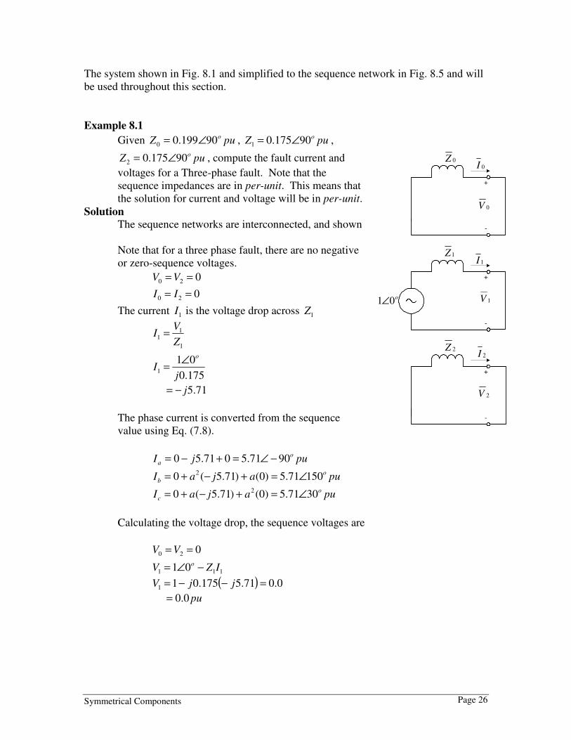
Example 8.1
Given puZo90199.00 ∠= , puZ o90175.01 ∠= ,
puZ o90175.02 ∠= , compute the fault current and
voltages for a Three-phase fault. Note that the
sequence impedances are in per-unit. This means that
the solution for current and voltage will be in per-unit.
Solution
The sequence networks are interconnected, and shown
Note that for a three phase fault, there are no negative
or zero-sequence voltages.
020 == VV
020 == II
The current 1I is the voltage drop across 1Z
1
11
Z
VI =
175.0
011
jI
o∠=
71.5j−=
The phase current is converted from the sequence
value using Eq. (7.8).
pujIo
a 9071.5071.50 −∠=+−=
puajaIo
b 15071.5)0()71.5(0 2 ∠=+−+=
puajaIo
c 3071.5)0()71.5(0 2 ∠=+−+=
Calculating the voltage drop, the sequence voltages are
020 == VV
111 01 IZV o −∠=
( ) 0.071.5175.011 =−−= jjV
pu0.0=
2I
+
-
2V
0I
+
-
0V
0Z
2Z
1I
+
-
1Vo01∠
1Z

Symmetrical Components Page 27
The phase voltages are converted from the sequence value using Eq. (7.6).
puVa 0.00.00.00.0 =++=
puaaVb 0.0)0.0()0.0(0.0 2 =++=
puaaVc 0.0)0.0()0.0(0.0 2 =++=
The per-unit value for the current and voltage
would now be converted to actual values using
Eq. (5.9) and Eq. (5.10) and knowing the base
power and voltage for the given system. See
example 5.1 for a reference.
The currents and voltages can be shown in phasor
form.
Example 8.2
Given puZo90199.00 ∠= , puZ o90175.01 ∠= ,
puZ o90175.02 ∠= , compute the fault current and
voltages for a Single line-to-ground fault. Note that
the sequence impedances are in per-unit. This
means that the results for current and voltage will
be in per-unit.
Solution
The sequence networks are interconnected in series,
as shown.
Because the sequence currents are in series, and
using ohms law.
210 III ==
)( 210
10
ZZZ
VI
++=
)175.0175.0199.0(
010
jjjI
o
++
∠=
puj 82.1−=
The phase currents are converted from the sequence
value using Eq. (7.8). Substituting 210 III == into
2I
+
-
2V
0I
+
-
0V
0Z
2Z
1I
+
-
1Vo01∠
1Z
Ic
Ia
Ib
VaVb
Vc

Symmetrical Components Page 28
Eq. (7.8) gives
0000 3IIIIIa =++=
000
2
0 =++= aIIaIIb
00
2
00 =++= IaaIIIc
Refer to Table 3.2: ( )01 2 =++ aa
Note that 03IIa = . This is the quantity that the relay “see’s” for a Single Line-to-
Ground fault.
Substituting pujI 82.10 −=
)82.1(303 jIIa −==
puj 46.5−=
Calculating the voltage drop, the sequence voltages are
000 IZV −=
111 IZVV −=
222 IZV −=
Substituting in the impedance and current from above
362.0)82.1(199.00 −=−−= jjV
( ) 681.082.1175.011 =−−= jjV
( ) 319.082.1175.02 −=−−= jjV
The phase voltages are converted from the sequence value using
Eq. (7.6).
0319.0681.0362.0 =−+−=aV
puaaVo
b 238022.1)319.0()681.0(362.0 2 ∠=−++−=
puaaVo
c 122022.1)319.0()681.0(362.0 2 ∠=−++−=
The per-unit value for the current and voltage would now be converted to actual
values using Eq. (5.9) and Eq. (5.10) and knowing the base power and voltage for
the given system. See example 5.1 for a reference.
The currents and voltages can be shown in phasor form.
Ia
Va
Vb
Vc

Symmetrical Components Page 29
Example 8.3
Given puZo90199.00 ∠= , puZ o90175.01 ∠= ,
puZ o90175.02 ∠= , compute the fault current and
voltages for a Line-to-Line fault. Note that the
sequence impedances are in per-unit. This means that
the solution for current and voltage will be in per-
unit.
Solution
The sequence networks are interconnected, as shown.
Because the sequence currents sum to one node, it
follows that
21 II −=
The current 1I is the voltage drop across 1Z in series
with 2Z
21
11
ZZ
VI
+=
175.0175.0
011
jjI
o
+
∠=
puj 86.2−=
pujI 86.22 +=
00 =I
The phase current is converted from the sequence value using Eq. (7.8).
pujjIa 086.286.20 =+−=
pujajaIb 95.4)86.2()86.2(0 2 −=+−+=
pujajaIc 95.4)86.2()86.2(0 2 =+−+=
Calculating the voltage drop, and referring to Fig. 8.7, the sequence voltages are
21 VV =
222 IZV −=
)86.2)(75.1( jj−=
pu5.0=
00 =V
2I
+
-
2V
0I
+
-
0V
0Z
2Z
1I
+
-
1Vo01∠
1Z

Symmetrical Components Page 30
The phase voltages are converted from the sequence value using Eq. (7.6).
puVa 0.15.05.00.0 =++=
puaaVb 5.0)5.0()5.0(0.0 2 −=++=
puaaVc 5.0)5.0()5.0(0.0 2 −=++=
The per-unit value for the current and
voltage would now be converted to actual
values using Eq. (5.9) and Eq. (5.10) and
knowing the base power and voltage for the
given system. See example 5.1 for a
reference.
The currents and voltages can be shown in phasor form.
Example 8.4
Given puZo90199.00 ∠= , puZ o90175.01 ∠= , puZ o90175.02 ∠= , compute the
fault current and voltages for a Double Line-to-Ground fault. Note that the
sequence impedances are in per-unit. This means that the solution for current and
voltage will be in per-unit.
Solution
The sequence networks are interconnected, as
shown in Fig. 8.9
Because the sequence currents sum to one node,
it follows that
)( 201 III +−=
The current 1I is the voltage drop across 1Z in
series with the parallel combination of 0Z and
2Z
++
=
20
201
11
ZZ
ZZZ
VI
Substituting in oV 011 ∠= , and 0Z , 1Z , and 2Z ,
then solving for 1I
2I
+
-
2V
0I
+
-
0V
0Z
2Z
1I
+
-
1Vo01∠
1Z
Ic
IbVaVb
Vc

Symmetrical Components Page 31
pujI 73.31 −=
1
20
20
)(I
ZZ
ZI
+=
75.1j+=
1
20
02
)(I
ZZ
ZI
+=
99.1j+=
The phase current is converted from the sequence value using Eq. (7.8).
pujjjIa 099.173.375.1 =+−=
pujajajIo
b 1.15260.5)99.1()73.3(75.1 2 ∠=+−+=
pujajajIo
c 9.2760.5)99.1()73.3(75.1 2 ∠=+−+=
Calculating the voltage drop, and referring to Fig. 8.9, the sequence voltages are
210 VVV ==
000 IZV −=
)199.0)(75.1( jj−=
pu348.0=
The phase voltages are converted from the sequence value using Eq. (7.6).
puVa 044.1348.0348.0348.0 =++=
puaaVb 0)348.0()348.0(348.0 2 =++=
puaaVc 0)348.0()348.0(348.0 2 =++=
Refer to Table 3.2: ( )01 2 =++ aa
The per-unit value for the current and voltage would
now be converted to actual values using Eq. (5.9) and
Eq. (5.10) and knowing the base power and voltage
for the given system. See example 5.1 for a
reference.
The currents and voltages can be shown in phasor
form.
IcIb
Va
IR

Symmetrical Components Page 32
9. Oscillograms and Phasors
Attached are four faults that were inputted into a relay and then captured using the relay
software.
Three-phase fault. Compare to example (8.1)
Fig 9.1a
Fig 9.1b Fig 9.1c

Symmetrical Components Page 33
Single Line-to-Ground fault. Compare to example (8.2)
Fig 9.2a
Fig 9.2b Fig 9.2c

Symmetrical Components Page 34
Line-to-Line fault. Compare to example (8.3)
Fig 9.3a
Fig 9.3b Fig 9.3c

Symmetrical Components Page 35
Double Line-to-Ground fault. Compare to example (8.4)
Fig 9.4a
Fig 9.4b Fig 9.4c

Symmetrical Components Page 36
10. Addition Symmetrical Components considerations
10.1 Symmetrical Components into a Relay
Using a directional ground distance relay it will be demonstrated how sequential
components are used in the line protection. To determine the direction of a fault, a
directional relay requires a reference against which the line current can be compared.
This reference is known as the polarizing quantity. Zero-sequence line current can be
referenced to either zero-sequence current or zero-sequence voltage, or both may be used.
The zero-sequence line current is obtained by summing the three-phase currents. See
Fig. 10.1
From Eq. (7.9)
( ) rcba IIIII ==++ 03 (10.1)
This is known as the residual current or simply 03I .
The zero-sequence voltage at or near the bus can be used for directional polarization.
The polarizing zero-sequence voltage is obtained by adding an auxiliary potential
transformer to the secondary voltage. The auxiliary transformer is wired as a broken-
delta and the secondary inputted to the relay. See Fig 10.2

Symmetrical Components Page 37
03V
aV
bV
cV
AV
BV
CV
ΦA ΦB ΦC
From Eq. (7.7a) the zero-sequence voltage equals
( )cba VVVV ++=3
10 (10.2a)
( )cba VVVV ++=03 (10.2a)
Example 10.1
Using the values obtained from example 8.2, calculate 03V .
Solution
0=aV
puVo
b 238022.1 ∠=
puVo
c 122022.1 ∠=
oo
V 122022.1238022.103 0 ∠+∠+=
puo18008.1 ∠=
The zero-sequence voltage is puo18008.1 ∠ . By connecting the value in the reverse
gives 03V− which equals puo008.1 ∠ . Plotting this, we can show in phasor form what
the relay see’s, Ia lagging 03V− by the line angle. In this case resistance is neglected,
therefore Ia lags by 90o. (see Fig 10.3).
Symmetrical Components Page 38
Ia
Va
Vb
Vc
3V0 -3V0
Fig 10.3
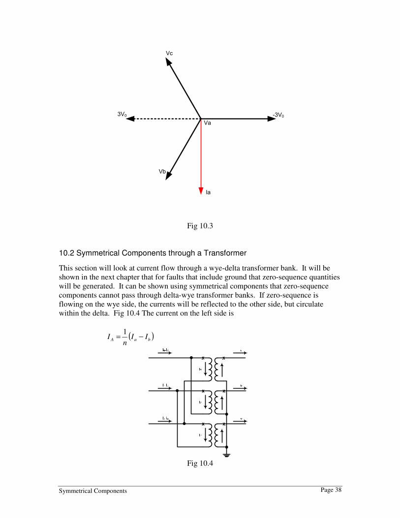
10.2 Symmetrical Components through a Transformer
This section will look at current flow through a wye-delta transformer bank. It will be
shown in the next chapter that for faults that include ground that zero-sequence quantities
will be generated. It can be shown using symmetrical components that zero-sequence
components cannot pass through delta-wye transformer banks. If zero-sequence is
flowing on the wye side, the currents will be reflected to the other side, but circulate
within the delta. Fig 10.4 The current on the left side is
( )baA IIn
I −=1
Fig 10.4

Symmetrical Components Page 39
From equation 7.2 we have
210 AAAA IIII ++= (10.3 a)
210 BBBB IIII ++= (10.3 b)
Substituting on the right side of the equation 8.1 gives
)( BA II − = )()()( 221100 BABABA IIIIII −+−+− (10.4)
The zero-sequence currents are in-phase, therefore equation 10.3 simplifies to
)( BA II − = )()( 2211 BABA IIII −+− (10.5)
Where o
ABA III 303)( 111 ∠=− and o
BBA III 303)( 222 −∠=−
)303()303(1
21
o
A
o
Aa IIn
I −∠+∠=
)3030(3
21
o
A
o
Aa IIn
I −∠+∠= (10.6)
In a balanced system where there is no negative or zero-sequence current then equation
10.6 reduces to
)30(3 o
Aa In
I ∠= (10.7)
As can be seen the current will shift by 30o
when transferring through a transformer
connected delta-wye. The same can be prove when looking at the voltages.
Now consider the connection in Fig 10.5.
anI
bnI
cnI
Fig 10.5
( )caA IInI −=

Symmetrical Components Page 40
Substituting equation 7.2 and reducing gives
)( CA II − = )()()( 221100 CACACA IIIIII −+−+− (10.8)
)303()303( 21
o
A
o
Aa IInI ∠+−∠=
)3030(3 21
o
A
o
Aa IInI ∠+−∠= (10.9)
As seen from the prior example equation 10.9 will reduce to
)30(3 o
Aa InI −∠=
if there is no negative or zero-sequence current, which is the case for a balanced system.
By inspection of the equations above for ANSI standard connected delta-wye transformer
banks if the positive-sequence current on one side leads the positive current on the other
side by 30o, the negative-sequence current correspondingly will lag by 30
o. Similarly if
the positive-sequence current lags in passing through the bank, the negative-sequence
quantities will lead 30o.
The direction of the phase shifts between the delta-connected winding and the wye-
connected winding depends on the winding connections of the transformer.
The winding configurations of a transformer will determine whether or not zero-sequence
currents can be transformed between windings. Because zero-sequence currents do not
add up to zero at a neutral point, they cannot flow in a neutral without a neutral conductor
or a ground connection. If the neutral has a neutral conductor or if it is grounded, the
zero-sequence currents from the phases will add together to equal 3I0 at the neutral point
and then flow through the neutral conductor or ground to make a complete path.
Following are some different transformer winding configurations and their effect on zero-
sequence currents
1. Transformers with at least two grounded wye windings
When a transformer has at least two grounded-wye windings, zero-sequence
current can be transformed between the grounded-wye windings. The I0 currents
will add up to 3I0 in the neutral and return through ground or the neutral
conductor. The I0 currents will be transformed into the secondary windings and
flow in the secondary circuit. Any impedance between the transformer neutral
points and ground must be represented in the zero-sequence network as three
times its value to correctly account for the zero-sequence voltage drop across it.
Below on the left is a three-phase diagram of a grounded-wye, grounded-wye
transformer connection with its zero-sequence network model on the right.
Notice the resistance in the neutral of the secondary winding is modeled by 3R in
the zero-sequence network model.

Symmetrical Components Page 41
2. Transformers with a grounded-wye winding and a delta winding
When a transformer has a grounded-wye winding and a delta winding, zero-
sequence currents will be able to flow through the grounded-wye winding of the
transformer. The zero-sequence currents will be transformed into the delta
winding where they will circulate in the delta without leaving the terminals of the
transformer. Because the zero-sequence current in each phase of the delta
winding is equal and in phase, current does not need to enter or exit the delta
winding. Below on the left is a three-phase diagram of a grounded-wye-delta
transformer connection with its zero-sequence network model on the right.
Reference Bus
Z0 3RP S
I0
I0
I0
3I03I0
R
I0
I0
I0
P S

Symmetrical Components Page 42
3. Autotransformers with a grounded neutral
Autotransformers can transform zero-sequence currents between the primary and
secondary windings if the neutral is grounded. Zero-sequence current will flow
through both windings and the neutral ground connection. Below on the left is a
three-phase diagram of a grounded neutral autotransformer with its zero-sequence
network model on the right.
4. Autotransformers with a delta tertiary
If an autotransformer has a delta tertiary, zero-sequence current can flow through
either the primary or secondary winding even if the other winding is open
circuited in the same manner that zero-sequence current can flow in a grounded-
wye-delta transformer. If the ground is removed from the neutral, zero-sequence
current can still flow between the primary and secondary windings, although there
will not be any transformation of currents between the primary and secondary
windings—only between the partial winding between the primary and secondary
terminals and the delta tertiary. This is not a normal condition though, so it will
not be analyzed here.
Note that when modeling three-winding transformers the impedance needs to be
broken into the impedance of the individual windings.

Symmetrical Components Page 43
5. Other transformers
Other transformer configurations, such as ungrounded wye-ungrounded wye,
grounded wye-ungrounded wye, ungrounded wye-delta, and delta-delta will not
allow zero-sequence currents to flow and will have an open path in the zero-
sequence network model. Some of these configurations are shown below with
their zero-sequence network models.
In the preceding transformer connection diagrams the values of I0 at the terminals of the
primary and secondary windings will be equal on a per-unit basis. They will also have
the same per-unit values within the wye and delta windings; however, the per-unit values
of current within the windings of an autotransformer are somewhat more difficult to
determine because part of the winding carries both primary and secondary currents. If
the magnitude of current within the winding of an autotransformer needs to be known, it
can be determined by equating the ampere turns of the primary winding to those of the
secondary winding and solving. If a tertiary is involved, it will need to be included in the
equation also.

Symmetrical Components Page 44
Magnitude of transformer zero-sequence impedance
The zero-sequence impedance of a single-phase transformer is equal to the positive-
sequence impedance. When three single-phase units are connected as a three-phase unit
in a configuration that will transform zero-sequence currents (grounded wye-grounded
wye, grounded wye-delta, etc.), the zero-sequence impedance of the three-phase unit will
normally be equal to the positive-sequence impedance.
In transformers built as three-phase units, i.e. with a three-phase core, in a configuration
capable of transforming zero-sequence currents, the zero-sequence impedance will be the
same as the positive-sequence impedance if the transformer core is of the shell type. If
the core is of the core type, the zero-sequence impedance will be different than the
positive-sequence impedance. This is because the zero-sequence excitation flux does not
sum to zero where the three legs of the core come together and is forced to travel outside
of the iron core, through the oil or the transformer tank where the magnetic permeability
is much less than the iron core. This results in a low impedance (high conductance) in
the magnetizing branch of the transformer model. The larger zero-sequence magnetizing
current results in a lower apparent zero-sequence impedance. Using a lower value of
zero-sequence impedance in the transformer zero-sequence model is sufficient for most
fault studies, but to obtain a highly accurate zero-sequence model of a three-phase core-
form transformer, the magnetizing branch can not be neglected.
11. System Modeling
11.1 System Modeling: Transmission Lines Transmission lines are represented on a one-line diagram as a simple line connecting
busses or other circuit elements such as generators, transformers etc.
Transmission lines are also represented by a simple line on impedance diagrams, but the
diagram will include the impedance of the line, in either ohm or per-unit values.
Sometimes the resistive element of the impedance is omitted because it is small
compared to the reactive element.
Here is an example of how a transmission line would be represented on an impedance
diagram with impedances shown in ohms:
In a balanced three-phase system the impedance of the lines and loads are the same, and
the source voltages are equal in magnitude. We can calculate the single-phase current,
but must take into account the voltage drop across the mutual impedance caused by the
other phase currents. From Fig 11.1, the voltage drop in A-phase is

Symmetrical Components Page 45
Zs
Zs
Zs
Zm
Zm
Zm
AΦ
BΦ
CΦ
Fig 11.1
CmBmASa IZIZIZV ++= (11.1a)
For the case of a balanced three-phase current ACB III −=+ )( . Therefore:
( ) AmSa IZZV −= (11.1b)
Dividing by IA shows the positive-sequence impedance of the line equals the self
impedance minus the mutual impedance.
( )mS
A
Aa ZZ
I
VZ −==
0
01 (11.2)
The negative-sequence current encounters a negative-sequence impedance which is equal
to the positive-sequence impedance
( )mS
A
Aa ZZ
I
VZ −==2 (11.3)
For the zero-sequence impedance, because Ia0, Ib0 and Ic0 are in phase with each other,
000 CBA III ==
then zero-sequence voltage drop is given in equation 11.4
( ) 000000 AmmASCmBmASa IZZIZIZIZIZV ++=++= (11.4a)
( ) 00 2 AmSa IZZV += (11.4b)
Dividing each side by IA0 give the zero-sequence impedance:
( )mS
A
Aa ZZ
I
VZ 2
0
00 +== (11.5)
The result gives the zero-sequence impedance as function of the self and mutual
impedance of the line. The zero-sequence impedance is always larger than the positive-
sequence because we are adding two times the mutual impedance to the self impedance,
instead of subtracting the mutual impedance from the self impedance.

Symmetrical Components Page 46
11.2 System Modeling: Subtransient, Transient, and Synchronous Reactance of Synchronous Generators
A synchronous generator is modeled by an internal voltage source in series with an
internal impedance.
Below is a typical one-line diagram symbol for a generator.
The circle represents the internal voltage source. The symbol to the left of the circle
indicates that the three phases of the generator are wye-connected and grounded through
a reactance. The symbol for a synchronous motor is the same as a synchronous generator.
A typical impedance diagram representation of a synchronous generator is shown in Fig.
11.2.
Xg Rg
VtEg
+
-
Fig. 11.2
When modeling the impedance of a synchronous generator (or motor), the resistive
component is usually omitted because it is small compared to the reactive component.
When a fault is applied to a power system supplied by a synchronous generator, the initial
current supplied by the generator will start at a larger value, and over a period of several
cycles it will decrease from its initial value to a steady state value.
The initial value of current is called the subtransient current or the initial symmetrical rms
current. Subtransient current decreases rapidly during the first few cycles after a fault is
initiated, but its value is defined as the maximum value that occurs at fault inception.
After the first few cycles of subtransient current, the current will continue to decrease for
several cycles, but at a slower rate. This current is called the transient current. Although,
like the subtransient current, it is continually changing, the transient current is defined as
its maximum value, which occurs after the first few cycles of subtransient current.
After several cycles of transient current, the current will reach a final steady state value.
This is called the steady state current or the synchronous current.
Symmetrical Components Page 47
The reason why the current supplied by the synchronous generator is changing after a
fault is because the increased current through the armature of the generator creates a flux
that counteracts the flux produced by the rotor. This results in a reduced flux through the
armature and therefore a reduced generated voltage. However, because the decrease in
flux takes time, the generator voltage will be initially higher and decrease over time.
We account for the changing generator voltage in our model by using different values of
reactance in series with the internal generator voltage.
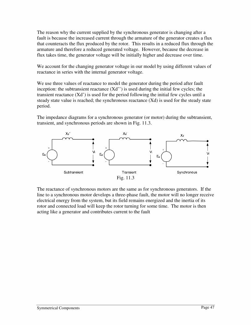
We use three values of reactance to model the generator during the period after fault
inception: the subtransient reactance (Xd’’) is used during the initial few cycles; the
transient reactance (Xd’) is used for the period following the initial few cycles until a
steady state value is reached; the synchronous reactance (Xd) is used for the steady state
period.
The impedance diagrams for a synchronous generator (or motor) during the subtransient,
transient, and synchronous periods are shown in Fig. 11.3.
Fig. 11.3
The reactance of synchronous motors are the same as for synchronous generators. If the
line to a synchronous motor develops a three-phase fault, the motor will no longer receive
electrical energy from the system, but its field remains energized and the inertia of its
rotor and connected load will keep the rotor turning for some time. The motor is then
acting like a generator and contributes current to the fault

Symmetrical Components Page 48
11.3 System Modeling: Transformers Transformers are represented in one-line diagrams by several symbols. Below are some typical ones.
The first is a two-winding transformer connected delta- grounded wye, and the second is a three-winding transformer connected grounded wye-delta-grounded wye. An impedance model of a practical two-winding transformer is shown in Fig. 11.4.
Fig. 11.4
In the model, a:1 represents the winding ratio of the ideal transformer shown by the two coupled coils, BL in parallel with G represents the magnetizing susceptance and conductance which make up the magnetizing branch, IE represents the excitation current, r1 and x1 represent the leakage impedance of winding 1,r2 and x2 represent the leakage impedance of winding 2, V1 and I1 represents the primary voltage and current respectively, and V2 and I2 represent the secondary voltage and current respectively. Because normal fault and load currents are very much larger than the magnetizing current, IE, we can omit the magnetizing branch from our model. We can also omit the ideal transformer if we refer the leakage impedances to either the primary- or secondary-side of the transformer. The leakage impedance of one side of the transformer can be referred to the other side of the transformer by multiplying it by the square of the turns ratio. Below is the simplified impedance diagram with the magnetizing branch removed and the leakage impedance of the secondary winding referred to the primary side of the transformer.

Symmetrical Components Page 49
Our impedance model can be further simplified by letting 2211 rarR +=
2211 xaxX +=
When using this simplified model, any impedances and voltages connected to the
secondary side of the circuit must now be referred to the primary side.
As an example, the following transformer model will be converted to the simplified
impedance model. The magnetizing branch and the leakage resistances have been omitted
to simplify the problem.
The secondary-side impedance is multiplied by the square of the turns ratio before being
transferred to the primary side.
j6.0 * 8.332 = j416.3Ω

Symmetrical Components Page 50
This is added to the high side to get an impedance of j50Ω + j416.3Ω = j466.3Ω
The simplified model is shown in Fig. 11.5
Fig. 11.5
11.4 Some additional points – DC Offset In a transmission network, the sudden occurrence of a short circuit will result in a
sinusoidal current that is initially larger and decreases due to the changing air gap flux in
the synchronous generators. We’ve seen that this is modeled by subtransient, transient,
and synchronous reactances in our generator model. In a circuit containing resistance and
inductance (RL circuit), such as in a transmission network, the sudden occurrence of a
short circuit will also result in DC offset in the current that occurs after a fault is applied.
Consider the RL circuit below:
If the switch is closed at time t=0, the voltage around the circuit is
Vmaxsin(ωt+φ) = Ri + Ldi/dt
Solving this differential equation for the instantaneous current, i, gives
i = Vmax [sin(ωt+φ-θ) – e-Rt/Lsin(φ-θ)] / Z
Where Z= √(R2 + (ωL)2 and θ = tan-1(ωL/R)

Symmetrical Components Page 51
The important thing to note from the solution is that there is a sinusoidal component that
represents the steady-state solution for the current (Vmax sin(ωt+φ-θ) / Z) and a
exponentially decaying component (-Vmax e-Rt/Lsin(φ-θ) / Z).
Some points to note about the exponentially decaying—or DC offset—component:
The initial value of the DC offset is determined by what point in the cycle the voltage
waveform is at when the fault occurs (the value of φ) and will range from 0 up to the
value of the steady state component.
The dc component will decrease with a time constant of L/R. The larger the ratio of
inductance to resistance in the circuit, the larger the time constant, and the slower the dc
component will decay.
Three time constants after the switch is closed, the dc offset will have decayed to 5% of
its initial value.
DC offset is an important consideration in sizing breakers.
Most modern microprocessor-based relays are immune to DC offset because after the
analog signals are converted to digital signals, they can be mathematically filtered to
remove the DC component. Therefore the DC component doesn’t need to be considered
in the relay settings.
Some electromechanical relays are immune to DC offset, and some aren’t. Clapper and
plunger type units are generally not immune, and DC offset will have to be allowed for in
the relay settings (one guideline is to set pickup at 160% of the desired ac pickup
current). Cylinder type units, used in distance relays, are immune to DC offset.
The different values of the AC fault current should be considered in the relay settings.
The subtransient fault current should be used in setting instantaneous current elements,
whereas the synchronous fault current should be used in current elements with long time
delays.

Symmetrical Components Page 52
Problems Problem 1
BPA’s system model uses a three-phase power base of 100MVA. The line-to-line
voltage base is 525kV for the 500 system, 230kV for the 230 system, and 115kV for the
115 system.
a) An undervoltage relay on the 115 system is set to pick up at 0.85 pu (per unit) of the
phase-to-ground voltage. What is the phase-to-ground voltage that the undervoltage relay
will pick up at?
b) A three-phase fault on the 500 system results in a fault current of 2750A. What is the
per unit value of this current?
c) What is the base impedance for the 500 system?
d) What is the base impedance for the 230 system?
e) What is the base impedance for the 115 system?
Problem 2
From our example 5.2, the percent impedance of a 525/241.5kV autotransformer is
10.14% based on its nameplate value of 900MVA. Suppose we need to model this
transformer in BPA’s ASPEN model which uses a 100MVA power base. What would
the per-unit impedance be?
Problem 3
From our example in 5.2, convert the per-unit impedance to a per-unit value in a three-
phase power base of 100MVA.
a) First convert the per unit impedance to an actual impedance (in ohms) at 525kV and
then convert the actual impedance to a per-unit impedance on the new base.
b) Repeat, this time converting the per unit impedance to an actual impedance (in ohms)
at 241.5kV and then converting the actual impedance to a per-unit impedance on the new
base
Problem 4
Convert the per-unit impedance of the transformer in the example to a per-unit value in
the BPA model with a three-phase power base of 100MVA by first converting the per
unit impedance to an actual impedance (in ohms) at 230 kV and then converting the
actual impedance to a per-unit impedance on the new base.

Symmetrical Components Page 53
Problem 5
V2
j6.0O
8.33:1
V1 = 66.4kV @ 0°
I2I1
j50.0O
50O
Using the transformer model convert from ohms to per-unit.
The voltage base for the primary side will be 115kV, and the voltage base for the
secondary side will be 13.8kV. The power base for both sides is 100MVA.
Problem 6
Below is a one line diagram of a partial power system.
The two generators are identical, each rated 13.8kV and 50MVA with a subtransient
reactance of Xd” = 15%. The two generators are tied to a common bus which is
connected to a transmission line with a delta-grounded wye transformer rated at
150MVA, 13.8kV/115kV and an impedance of 9.7%. The transmission line is 30 miles
long and has an impedance of 5.43 + j22.5Ω. At the end of the transmission line is a
grounded wye-grounded wye transformer, rated 225MVA, 115kV/230kV with an
impedance of 7.4% that connects the line to a 230kV bus. The remaining power system
connected to the 230kV bus is not shown.
From the above information, draw the impedance diagram with impedances shown in
their per-unit values. Use voltage bases of 13.8kV, 115kV, and 230kV for the
corresponding parts of the system, and use a power base of 100MVA for the whole
system.
Problem 7
From the impedance diagram, determine the per-unit and ampere values of subtransient
current in each generator and at the fault for a three-phase fault applied on the 230kV bus
with both generators operating at 1.0pu voltage.
Symmetrical Components Page 54
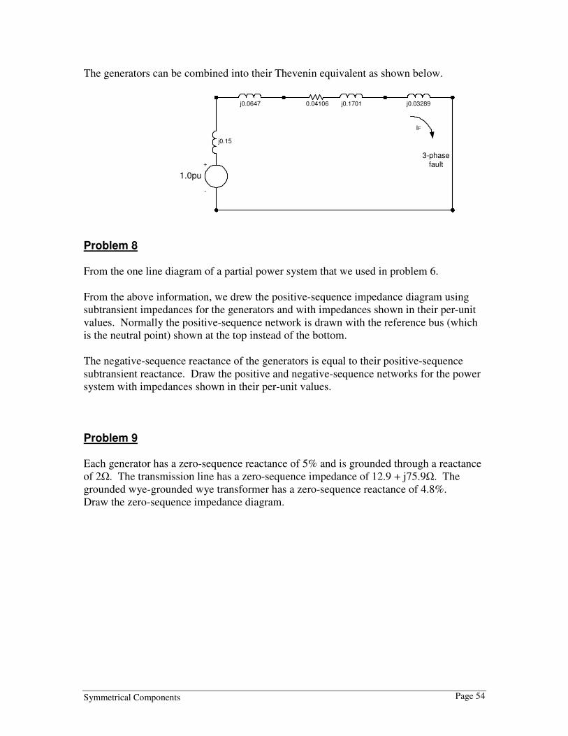
The generators can be combined into their Thevenin equivalent as shown below.
1.0pu
+
-
j0.15
j0.0647 j0.1701 j0.03289
3-phasefault
0.04106
IF
Problem 8
From the one line diagram of a partial power system that we used in problem 6.
From the above information, we drew the positive-sequence impedance diagram using
subtransient impedances for the generators and with impedances shown in their per-unit
values. Normally the positive-sequence network is drawn with the reference bus (which
is the neutral point) shown at the top instead of the bottom.
The negative-sequence reactance of the generators is equal to their positive-sequence
subtransient reactance. Draw the positive and negative-sequence networks for the power
system with impedances shown in their per-unit values.
Problem 9
Each generator has a zero-sequence reactance of 5% and is grounded through a reactance
of 2Ω. The transmission line has a zero-sequence impedance of 12.9 + j75.9Ω. The
grounded wye-grounded wye transformer has a zero-sequence reactance of 4.8%.
Draw the zero-sequence impedance diagram.

Symmetrical Components Page 55
Solutions Problem 1
a) V BL-G = V BL-L / √3
V BL-G = 115kV / √3 = 66.4kV
Z PU = ZA / ZB
ZA = ZPU*ZB
ZA = 0.85*66.4kV
ZA = 56.4kV
b) IB = PB3Φ / √3*VBL-L
IB = 100x106 / √3*525x10
3
IB = 110.0 A
IPU = IA / IB
IPU = 2750 A / 110 A
IPU = 25.0 pu
c) ZB = VBL-L2 / PB3Φ
ZB = (525x103)
2 / 100x10
6
ZB = 2756.25Ω
d) ZB = VBL-L2 / PB3Φ
ZB = (230x103)
2 / 100x10
6
ZB = 529.0Ω
e) ZB = VBL-L2 / PB3Φ
ZB = (115x103)
2/ 100x10
6
ZB = 132.25Ω
Problem 2
Zpu new = Zpu old *(VBL-L old / VBL-L new)2 * (PB3Φ new / PB3Φ old)
Zpu old = 10.14 / 100 = 0.1014
VBL-L old = 525kV, PB3Φ old = 900MVA
VBL-L new = 525kV, PB3Φ new =100MVA
Zpu new = 0.1014 *(525kV / 525kV)2 * (100MVA / 900MVA)
Zpu new = 0.1014 *1* (100 / 900)
Zpu new = 0.01127 pu

Symmetrical Components Page 56
Problem 3
ZPU = ZA / ZB
ZA = ZPU * ZB
ZB = VBL-L 2 / P B3Φ
a) Using the high-side voltage:
Z B old = 525,0002 / 900x10
6
Z B old = 306.25Ω
ZA = 0.1014 * 306.25
ZA = 31.05Ω
Converting to the 100MVA base:
ZB new = V BL-L new 2 / PB3Φ new
ZB new = 525,0002 / 100x10
6
ZB new = 2756.25Ω
ZPU new = ZA / ZB new
ZPU new = 31.05Ω / 2756.25Ω
ZPU new = 0.01127 pu
b) Using the low-side voltage:
ZB old = 241,5002 / 900x10
6
ZB old = 64.80Ω
ZA = 0.1014 * 64.80
ZA = 6.57Ω
Converting to the 100MVA base:
ZB new = V BL-L new 2 / P B3Φ new
ZB new = 230,0002 / 100x10
6
ZB new = 529.0Ω
ZPU new = ZA / ZB new
ZPU new = 6.57Ω / 529.0Ω
ZPU new = 0.01242 pu

Symmetrical Components Page 57
Problem 4
Repeat problem 3 assuming the transformer has a tap with a ratio of 525 /230 kV and
using the low side voltage.
Problem 5
Answer:
The base impedance of the secondary side is ZB = V BL-L2 / P B3Φ
ZB = (13.8*103)2 / 100*10
6
ZB = 1.904Ω
The per-unit impedance of the secondary leakage reactance is
X2 = j6.0 / 1.094 = j3.151 pu
The per-unit value of the load resistance is RL = 50 / 1.904 = 26.26 pu
The base impedance of the primary side is ZB = V BL-L2 / P B3Φ
ZB = (115*103)2 / 100*10
6
ZB = 132.25Ω
The per-unit impedance of the primary leakage reactance is
X1 = j50.0 / 132.25 = j0.3781 pu
The total per-unit impedance of our model can be obtained by simply adding together the
per-unit values of the primary and secondary impedances.
X = X1 + X2 = j0.3781 + j3.151 = j3.529 pu
V2 pu
j3.529 pu
I1 pu
V1 = 1.0 @ 0° pu 26.26 pu

Symmetrical Components Page 58
Problem 6
Answer:
Converting the impedances to per-unit on a 100MVA base using
Zpu new = Zpu old *(VBL-L old / VBL-L new)2 * (PB3Φ new / PB3Φ old)
Each generator subtransient reactance is Xd” = j0.15 * (13.8kV / 13.8kV)2 * (100MVA /
50MVA)
Xd” = j0.30 pu
The 13.8kV / 115kV transformer impedance is X = 0.097 * (13.8kV / 13.8kV)2 *
(100MVA / 150MVA)
X = j0.06467 pu
The base impedance for the 115kV line is ZB = V BL-L2 / P B3Φ
ZB = (115x103)2
/ 100x106 = 132.25Ω
The per-unit impedance of the 115kV transmission line is (5.43+j22.5) / 132.25 =
0.04106+j0.1701 pu
The 115kV / 230kV transformer impedance is X = 0.074 * (115kV / 115kV)2 *
(100MVA / 225MVA)
X = j0.03289 pu
The impedance diagram with the per-unit values of the impedances is shown below.
1.0pu
+
-
j0.30
j0.0647 j0.1701 j0.03289
1.0pu
+
-
3-phasefault
j0.30
0.04106

Symmetrical Components Page 59
Problem 7
Answer:
The fault current is
IF = 1.0 / (0.04106 + j0.15 + j0.0647 + j0.1701 + j0.03289)
IF = 1.0 / (0.04106 + j0.41769)
IF = 2.382 @ -84.4° pu
At the generators, the total fault current is I FGT = 2.382 * IB
IB = P B3Φ / √3*V BL-L = 100x106 / √3*13.8x10
3 = 4184 A
IFGT = 2.382 * 4184 = 9966 A
Each generator contributes half of this current
IFG = 9966 / 2 = 4983 A
At the fault, the total fault current is IF = 2.382 * IB
IB = P B3Φ / √3*V BL-L = 100x106 / √3*230x10
3 = 251.0 A
IF = 2.382 * 251.0 = 597.9 A
Problem 8
Ea = 1.0pu
+
-
j0.15
j0.0647 j0.1701 j0.032890.04106
Reference Bus
VA1
+
-
j0.15
j0.0647 j0.1701 j0.032890.04106
Reference Bus
VA2
+
-

Symmetrical Components Page 60
Problem 9
Answer:
The zero-sequence reactance of each generator is 5%, or 0.05pu on a 13.8kV, 50MVA
base. Converting this to a 100MVA base gives
Zpu new = j0.05 * (100 / 50) = j0.10 pu
Each generator is grounded through a reactance of 2Ω. The base impedance at 13.8kV,
100MVA is ZB = (13.8x10³)2 / (100x106) = 1.9044Ω. The per-unit impedance of each
grounding reactor is Zpu = j2.0 / 1.9044 = j1.05pu. The grounding reactances will need
to be multiplied by three for the zero-sequence network, giving a value of 3 * j1.05 =
j3.15pu.
Because a value is not given for the zero-sequence impedance of the delta-grounded wye
transformer, it can be assumed that the zero-sequence impedance is the same as the
positive-sequence impedance.
The zero-sequence impedance of the transmission line is 12.9 + j75.9Ω. The base
impedance at 115kV, 100MVA is ZB = (115x103)2 / (100x10
6) = 132.25Ω. Converting
the zero-sequence line impedance to a per-unit value gives ZL0 = (12.9 + j75.9) / 132.25 =
0.0975 + j0.574pu.
The zero-sequence impedance of the grounded wye-grounded wye transformer is 4.8%,
or j0.048pu on a base of 115kV, 225MVA. Converting to a 115kV, 100MVA base gives
Zpu new = j0.048 * (100 / 225) = j0.0213 pu
The zero-sequence network is shown below. Notice the interruption in the path caused
by the delta-wye transformer.
j0.10
j0.0647 j0.574 j0.0213
Reference Bus
j0.10
0.0975
j3.15 j3.15
VA0
+
-
Here is a simplified version of the zero-sequence network with the two generator
branches combined into an equivalent branch.

Symmetrical Components Page 61
j0.0647 j0.574 j0.0213
Reference Bus
j0.05
0.0975
j1.575
VA0
+
-

Symmetrical Components Page 62
Appendix Three Phase System
LLL IVS 3= , Θ= cos3 LLL IVP , Θ= sin3 LLL IVQ
Per-Unit First step in using per-unit is to select the base(s) for the system.
Sbase = Power base, in VA
Vbase = voltage base in V
Sbase = 100 MVA
Vbase = Nominal voltage rated line-
to-line
valuebase
valueactualunitper
_
_=−
100
_ valuepercentunitper =−
basebasebase ZI
IZ
V
V= pupupu ZIV =
ampereskV
kVAI
base
base
base3
= AamperesV
kVAI
base
base
base 251)230(3
100==
Ex: 230kV base, 100MVA base
PUZ
MVAMVA
Fault
Base
Fault = PUZ
II
Fault
Base
CurrentFault =_
ohmskVA
xkVZ
base
basebase
10002
= (in kVA) ohmsMVA
kVZ
base
basebase
2
= (in MVA)
100
2
base
base
VZ = (for a 100 MVA base)
base
puZ
ZZ
)(Ω= )(
2Ω⋅
= Z
kV
MVAZ
base
base
pu (in MVA)
( )2
100%
base
base
kV
ZMVAZ
Ω⋅= (percent in MVA)
2
⋅=
old
base
new
baseold
ohm
new
ohmkV
kVZZ (new impedance reflective through a transformer)
ohmsZ new
ohm 8.1230
1152.7
2
=
⋅=
Ex: 115kV line impedance on the 115kV side of a 230/115kV transformer

Symmetrical Components Page 63
Symmetrical Components
a Operator
oa 1201∠=
oa 24012 ∠=
13 =a
210 VVVVa ++=
21
2
0 aVVaVVb ++=
2
2
10 VaaVVVc ++=
( )cba VVVV ++=3
10
( )cba VaaVVV2
13
1++=
( )cba aVVaVV ++= 2
23
1
210 IIIIa ++=
21
2
0 aIIaIIb ++=
2
2
10 IaaIIIc ++=
( )cba IIII ++=3
10
( )cba IaaIII2
13
1++=
( )cba aIIaII ++= 2
23
1
( )cba IIII ++=03 (residual currents or sum of the three phase currents)

Symmetrical Components Page 64
Three-Phase fault
puZ
MVAMVA
Fault
BaseFault =
1
1Z
EI a=
002 == II
⋅
==
kV
kVA
ZII A
3
1001
1
1
AB IaI 2=
AB aII =
111 1 ZIE −=
002 == EE
0ne-line to ground fault
puZZZ
MVAMVA Base
Fault
021
3
++
⋅=
021
210
1
ZZZIII
++===
0210 3IIIII A =++=
0== cB II
111 1 ZIE −=
222 ZIE −=
000 ZIE −=
0Z
2Z
1Z
2I+
-
2V
0I+
-
0V
1I+
-
1Vo01∠
0Z
2Z
1Z
2I
+
-
2V
0I+
-
0V
1I+
-
1Vo01∠

Symmetrical Components Page 65
Line-Line fault, or Phase-to-phase fault
121
212
11
ZZZII =
+=−=
00 =I
0=AI
11
2
21
2
21
2
0 aIIaaIIaaIIaIIB +=+=++=
( )21
2
ZZ
EaaIB
+
−=
BC II −= when 21 ZZ =
111 1 ZIE −=
1222 EZIE =−=
00 =E
Double Line-Line fault, or Two phase to Ground fault
( )20
20
1
1
1
ZZ
ZZZ
I+
+=
102 III −=+
20
102
ZZ
IZI
+=
20
120
ZZ
IZI
+=
111 1 ZIE −=
1222 EZIE =−=
1000 EZIE =− 2I+
-
2V
0I+
-
0V
0Z
2Z
1I
+
-
1Vo01∠
1Z
0Z
2Z
1Z
2I+
-
2V
0I
+
-
0V
1I+
-
1Vo01∠

Symmetrical Components Page 66
References
Blackburn, J. L., Protective Relaying: Principles and Applications, Mercel Dekker, Inc., New
York, 1987
Gross, Charles A., Power System Analysis, John Wiley & Sons, Inc., 1986
ABB, Protective Relaying Theory and Applications, Mercel Dekker, Inc., New York, 2004
Wagner, C. F. and Evans, R. D., Symmetrical Components, Krieger Publishing Company,
Florida, 1933
Lantz, Martin J., Fault Calculations for Relay Engineers, Bonneville Power Administration, 1965