an introduction to computational modeling of lung …€¦ · an introduction to computational...
TRANSCRIPT
Aachen Institute for Advanced Study inComputational Engineering Science,
Faculty of Mechanical Engineering, RWTH Aachen
An Introduction toComputational Modeling of Lung Failure
and Current Approaches
Seminar Thesis
by
Katharina Immel
Supervisors:Prof. Roger A. Sauer, Ph.D.
Farshad Roobakhshan, M.Sc.
Aachen, Juli 1, 2016
Contents
1 Introduction 1
2 Medical Background 22.1 Anatomy of the Human Lung . . . . . . . . . . . . . . . . . . . . . . . . . . . . . . 2
2.1.1 Alveoli . . . . . . . . . . . . . . . . . . . . . . . . . . . . . . . . . . . . . 32.2 Respiration . . . . . . . . . . . . . . . . . . . . . . . . . . . . . . . . . . . . . . . 32.3 Lung Diseases and Lung Failure . . . . . . . . . . . . . . . . . . . . . . . . . . . . 4
3 Modeling of Alveolar Collapse 53.1 Tissue Model . . . . . . . . . . . . . . . . . . . . . . . . . . . . . . . . . . . . . . 53.2 Liquid Model and Collapse Mechanics . . . . . . . . . . . . . . . . . . . . . . . . . 7
3.2.1 Pressure Gradients . . . . . . . . . . . . . . . . . . . . . . . . . . . . . . . 73.2.2 Compliance . . . . . . . . . . . . . . . . . . . . . . . . . . . . . . . . . . . 73.2.3 Alveolar Surfactant and Surface Tension . . . . . . . . . . . . . . . . . . . . 83.2.4 Collapse . . . . . . . . . . . . . . . . . . . . . . . . . . . . . . . . . . . . 8
3.3 Numerical Methods . . . . . . . . . . . . . . . . . . . . . . . . . . . . . . . . . . . 9
4 Current Modeling Approaches 124.1 Review . . . . . . . . . . . . . . . . . . . . . . . . . . . . . . . . . . . . . . . . . 124.2 Drawbacks . . . . . . . . . . . . . . . . . . . . . . . . . . . . . . . . . . . . . . . 134.3 Example: Dynamic Liquid Membrane Model . . . . . . . . . . . . . . . . . . . . . 13
Bibliography I
i
1 Introduction
Lung diseases are some of the most common medical conditions in the world, affecting millions ofpeople every year. Smoking, infections, genetics, and accidents are responsible for most lung diseasesand injuries. Some of these diseases can lead to lung failure caused by the collapse of a lung or partsof it, especially the alveoli. Alveoli form the end of the respiratory tract and are responsible for thegas exchange of oxygen and carbon dioxide in the human body. In addition to diseases, artificialventilation which is often used in therapy of lung diseases, can cause lung failure as well.
Research concerning lung mechanics, collapse, and requiting aims to better understand the breath-ing process in healthy and diseased lungs in order to optimize treatment for lung diseases e.g. phar-maceuticals and artificial ventilation. As in vitro and in vivo experiments are very costly and com-plicated and can mostly only be realized with animal organs, computational simulation of respiratorymechanics seems to be a promising tool to analyze these processes and develop better treatments. Inmost mechanical engineering disciplines computational modeling, e.g. computational fluid dynamicsor structure mechanics, is already a well established tool to design, simulate and optimize proce-dures, machinery or simulate biological phenomena. However, lung collapse is a highly complicatedmulti-physics problem that still lacks a complete computational model that addresses all relevant phe-nomena. As it includes phenomena in different scales, tissue mechanics, structure mechanics, fluiddynamics, and biology it presents a number of unique challenges missing in more traditional compu-tational modeling applications. Most computational models so far only focus on one phenomena, suchas tissue damage or surfactant behavior, or use highly idealized parameters, e.g. simplified geometryand general models for tissue and surfactant behavior.
This thesis aims to give a short introduction into the modeling of lung collapse and describes thecurrent state of the art of numerical modeling of alveolus collapse. It puts special focus on the liquidlayer inside the alveolus and its effect on the collapse and reopening process. Chapter 2 providesthe necessary medical background of the lung, alveoli, and lung failure. Chapter 3 presents themathematical methods to describe the tissue mechanics, fluid layer, collapse, and numerical modeling.In Chapter 4, we present a review of current modeling approaches and their drawbacks. Finally, wepresent a recent example of a dynamic modeling approach for the liquid layer.
1

2 Medical Background
The lungs are the primary organs of respiration in humans and many other vertebrae. Their functionin the respiratory system is to extract oxygen from the air and transfer it into the bloodstream, and inreturn, release carbon dioxide from the bloodstream into the air.
2.1 Anatomy of the Human Lung
The respiratory system of humans is divided into two parts: the upper and the lower respiratory tract.The upper respiratory tract consists of the nose, mouth, and throat, while the lower part is formedby the windpipe (trachea) and the lungs. Humans have two lungs, a right and a left lung. They arelocated within the thoracic cavity of the chest (cf. Fig. 2.1). The lungs are enclosed within the pleuralsac, which divides each lung into sections called lobes. It protects the lungs and allows the lungs toexpand and deflate, without much friction.
Figure 2.1: Anatomy of a human lung [21].
The lung itself also consists of two parts: the leading air passages and the respiratory air passages.The leading air passages only transport the air deeper into the lungs and consist of the trachea andits main branches, the bronchi, and their subbranches, the bronchioles. The respiratory air passagesonly consist of the alveoli, which are situated at the end of the bronchioles [50]. Here, the actual gasexchange between air and blood takes place. All together, the lungs of an adult contain about 2,400kilometers of airways.
The lungs have two blood supplies: The pulmonary circulation sends deoxygenated blood fromthe right heart, for the purposes of receiving oxygen, and back to the left heart where the oxygenated
2
2 Medical Background
blood is pumped into the body. The bronchial circulation provides the lungs with oxygenated bloodfrom the left heart.
2.1.1 Alveoli
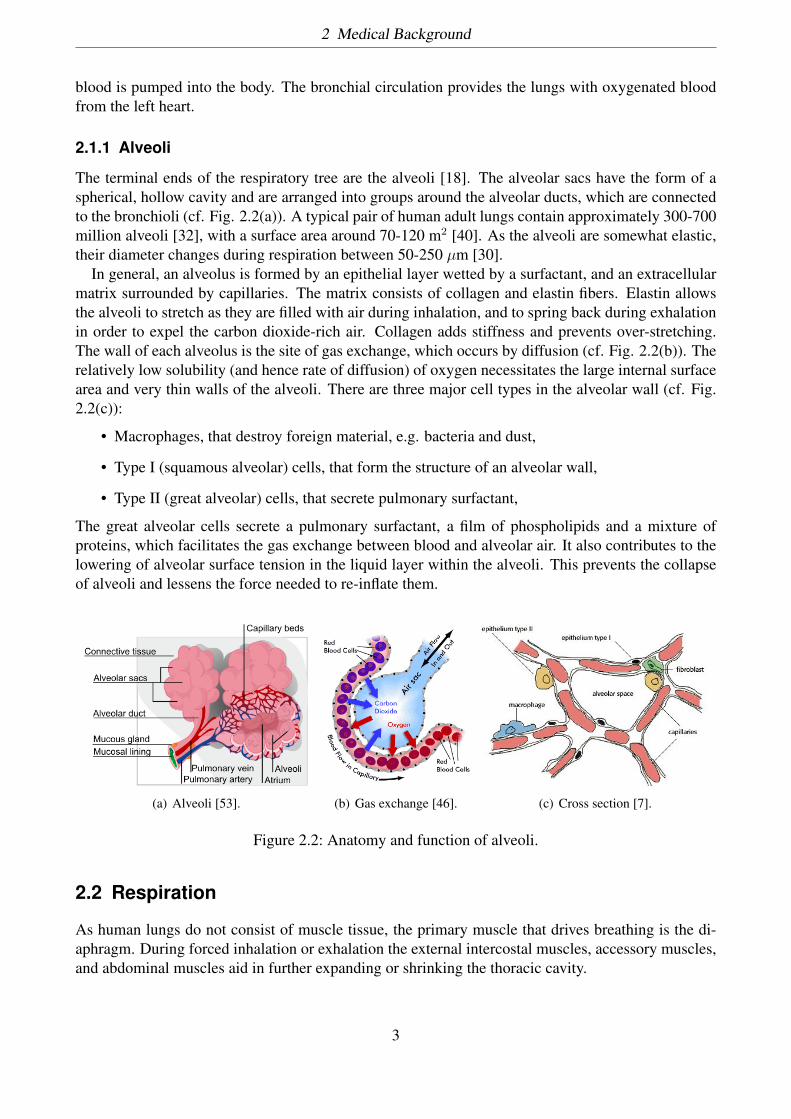
The terminal ends of the respiratory tree are the alveoli [18]. The alveolar sacs have the form of aspherical, hollow cavity and are arranged into groups around the alveolar ducts, which are connectedto the bronchioli (cf. Fig. 2.2(a)). A typical pair of human adult lungs contain approximately 300-700million alveoli [32], with a surface area around 70-120 m2 [40]. As the alveoli are somewhat elastic,their diameter changes during respiration between 50-250 µm [30].
In general, an alveolus is formed by an epithelial layer wetted by a surfactant, and an extracellularmatrix surrounded by capillaries. The matrix consists of collagen and elastin fibers. Elastin allowsthe alveoli to stretch as they are filled with air during inhalation, and to spring back during exhalationin order to expel the carbon dioxide-rich air. Collagen adds stiffness and prevents over-stretching.The wall of each alveolus is the site of gas exchange, which occurs by diffusion (cf. Fig. 2.2(b)). Therelatively low solubility (and hence rate of diffusion) of oxygen necessitates the large internal surfacearea and very thin walls of the alveoli. There are three major cell types in the alveolar wall (cf. Fig.2.2(c)):
• Macrophages, that destroy foreign material, e.g. bacteria and dust,
• Type I (squamous alveolar) cells, that form the structure of an alveolar wall,
• Type II (great alveolar) cells, that secrete pulmonary surfactant,
The great alveolar cells secrete a pulmonary surfactant, a film of phospholipids and a mixture ofproteins, which facilitates the gas exchange between blood and alveolar air. It also contributes to thelowering of alveolar surface tension in the liquid layer within the alveoli. This prevents the collapseof alveoli and lessens the force needed to re-inflate them.
(a) Alveoli [53]. (b) Gas exchange [46]. (c) Cross section [7].
Figure 2.2: Anatomy and function of alveoli.
2.2 Respiration
As human lungs do not consist of muscle tissue, the primary muscle that drives breathing is the di-aphragm. During forced inhalation or exhalation the external intercostal muscles, accessory muscles,and abdominal muscles aid in further expanding or shrinking the thoracic cavity.
3
2 Medical Background
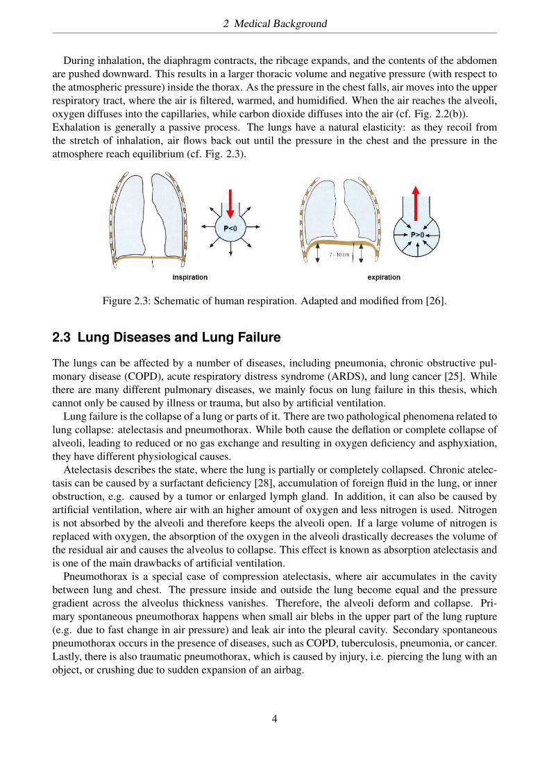
During inhalation, the diaphragm contracts, the ribcage expands, and the contents of the abdomenare pushed downward. This results in a larger thoracic volume and negative pressure (with respect tothe atmospheric pressure) inside the thorax. As the pressure in the chest falls, air moves into the upperrespiratory tract, where the air is filtered, warmed, and humidified. When the air reaches the alveoli,oxygen diffuses into the capillaries, while carbon dioxide diffuses into the air (cf. Fig. 2.2(b)).Exhalation is generally a passive process. The lungs have a natural elasticity: as they recoil fromthe stretch of inhalation, air flows back out until the pressure in the chest and the pressure in theatmosphere reach equilibrium (cf. Fig. 2.3).
Figure 2.3: Schematic of human respiration. Adapted and modified from [26].
2.3 Lung Diseases and Lung Failure
The lungs can be affected by a number of diseases, including pneumonia, chronic obstructive pul-monary disease (COPD), acute respiratory distress syndrome (ARDS), and lung cancer [25]. Whilethere are many different pulmonary diseases, we mainly focus on lung failure in this thesis, whichcannot only be caused by illness or trauma, but also by artificial ventilation.
Lung failure is the collapse of a lung or parts of it. There are two pathological phenomena related tolung collapse: atelectasis and pneumothorax. While both cause the deflation or complete collapse ofalveoli, leading to reduced or no gas exchange and resulting in oxygen deficiency and asphyxiation,they have different physiological causes.
Atelectasis describes the state, where the lung is partially or completely collapsed. Chronic atelec-tasis can be caused by a surfactant deficiency [28], accumulation of foreign fluid in the lung, or innerobstruction, e.g. caused by a tumor or enlarged lymph gland. In addition, it can also be caused byartificial ventilation, where air with an higher amount of oxygen and less nitrogen is used. Nitrogenis not absorbed by the alveoli and therefore keeps the alveoli open. If a large volume of nitrogen isreplaced with oxygen, the absorption of the oxygen in the alveoli drastically decreases the volume ofthe residual air and causes the alveolus to collapse. This effect is known as absorption atelectasis andis one of the main drawbacks of artificial ventilation.
Pneumothorax is a special case of compression atelectasis, where air accumulates in the cavitybetween lung and chest. The pressure inside and outside the lung become equal and the pressuregradient across the alveolus thickness vanishes. Therefore, the alveoli deform and collapse. Pri-mary spontaneous pneumothorax happens when small air blebs in the upper part of the lung rupture(e.g. due to fast change in air pressure) and leak air into the pleural cavity. Secondary spontaneouspneumothorax occurs in the presence of diseases, such as COPD, tuberculosis, pneumonia, or cancer.Lastly, there is also traumatic pneumothorax, which is caused by injury, i.e. piercing the lung with anobject, or crushing due to sudden expansion of an airbag.
4
3 Modeling of Alveolar Collapse
Since lung collapse can be caused by extrinsic and intrinsic effects, which can affect a single respi-ratory passage up to a whole lung, it is considered a multiscale problem. However, modeling andsimulating a complete lung with all its air passages and millions of alveoli is very complicated andtime consuming. In addition, most of the mechanisms are still not fully understood. It is also a highlycomplicated multiphysics problem: First of all, the geometry, tissue, and liquid lining have to bemodeled appropriately. Second, as we deal with collapse, we need to incorporate structure and con-tact mechanics. Last, due to the liquid lining, we have to model the fluid structure interaction (FSI)between the tissue and the fluid, as well as between the fluid and the air, which is essential for thecollapse and reopening process of alveoli. As a result of these complications most research groupsfocus on the modeling of one or just a few air passages or alveoli and only a few of the phenomenarelated to respiratory mechanics and collapse.
3.1 Tissue Model
This section will give a brief introduction in the necessary basics of nonlinear continuum mechanicsthat provide the governing equation of the structural part of the alveolus model [54]. For more detaileddescriptions refer to [20]. As an alveolus goes through large deformations, infinitesimal strain theorydoes not hold and finite strain or large strain theory should be used [41]. Nonlinearity occurs dueto the stress-strain behavior of the biological tissue and the geometrical variations, that significantlyaffect the load-deformation behavior.
We consider a material point with coordinates X in the reference configuration. As the point under-goes large deformation, it obtains coordinates x(X) in the deformed configuration. The correspondingdisplacement u and deformation gradient F are thus defined as
u(x) = x(X) − X, (3.1)
F = ∂x∂X
. (3.2)
The volume change
J ≡ detF (3.3)
should be positive, in order to keep the volumetric orientation of elements and is considered to beJ ≡ 1 for most biomaterials. The right and left Cauchy-Green deformation tensors are defined,respectively, as
C = FTF, (3.4)
b = FFT . (3.5)
Another relevant tensor is the material Green strain tensor E = 12(C − I), with the identity matrix I.
Constitutive behavior of elastic materials is a function of only the current state of deformation. For
5
3 Modeling of Alveolar Collapse
Lagrangian formulations, it is sufficient to only use the deformation gradient to calculate the Cauchystress at any material point, without considering other measures of strain:
σ = σ(F(X),X). (3.6)
Such a material is called Cauchy elastic. This model cannot describe hysteresis, stress softening,residual strains and other inelastic effects and is thus not suitable for biological tissues. For the caseof small deformations, this equation reduces to the classical Hooke’s law.
As a deformable body goes through a large deformation or if material does not behave linearly, aproper material model, e.g. hyperelasticity, is required. In the particular case of hyperelasticity, thematerial behavior does not depend on the deformation path. Thus, the work done by stresses onlydepends on the initial state in the reference configuration and current state in the deformed configu-ration. Consequently, a strain potential Ws per unit volume of undeformed body can be formulatedequal to work done by stresses during deformation, by
Ws = Ws(F(X),X) = Ws(C(X),X). (3.7)
A material is defined as Green elastic or hyperelastic, if the stress-strain relationship derives froma strain energy density function. The simplest example is the Saint-Venant-Kirchhoff model, whichextends the formulation for nonlinear behavior by
σ = 2J
F∂W
∂CFT , (3.8)
Ws = λ
4 (tr(C − I))2 + µ
2 tr((C − I)2). (3.9)
The Lamé parameters λ and µ can be expressed in terms of the Young’s modulus E and the Poissonratio ν as
µ = E
2(1 + ν) , (3.10)
λ = 1µν(1 − 2ν) . (3.11)
A special case of the hyperelastic material models is the compressible Neo-Hookean model
σ = λ
J(lnJ)I + µ
J(b − I), (3.12)
Ws = λ
2 (lnJ)2 + µ
2 (trC − 3) + µ(lnJ). (3.13)
Viscoelasticity is the property of materials that exhibit both viscous and elastic characteristics whenundergoing deformation. Viscous materials, like honey, resist shear flow and strain linearly with timewhen a stress is applied. Elastic materials strain when stretched and quickly return to their originalstate once the stress is removed. Viscoelastic materials have elements of both of these propertiesand, as such, exhibit time-dependent strain. Whereas elasticity is usually the result of bond stretchingalong crystallographic planes in an ordered solid, viscosity is the result of the diffusion of atoms ormolecules inside an amorphous material.
6
3 Modeling of Alveolar Collapse
As biological tissues are not homogeneous, but may consist of different cell types, layers, andfibers, one has to take into account material distribution and fiber orientation. Most biological tissuesare anisotropic, which means that their mechanical properties depend on the direction, in contrastto isotropy where material behavior is the same for all directions. One special case of anisotropy isorthotropy, which describes symmetry with respect to three mutually orthogonal planes, and can beused to describe arteries. Another is transverse isotropy, which describes material symmetry withrespect to only one axis.
3.2 Liquid Model and Collapse Mechanics
3.2.1 Pressure Gradients
Breathing is a mechanism caused by pressure gradients in the respiratory system. There are threedifferent pressure definitions which are of great importance in creating a pressure gradient in therespiratory system:
• Atmospheric pressure: air pressure at the input of system (mouth or nose)
• Alveolar pressure: pressure inside the alveolus
• Intra-pleural pressure: pressure inside the pleural space outside the lung
Across the alveolus wall, there is a transmural pressure gradient, also called transpulmonary pressure,which is defined as
Ptp = Palv − Pip, (3.14)
where Ptp, Palv and Pip are transpulmonary, alveolar and intrapulmonary pressure respectively. Thispressure gradient balances surface tension and elasticity of the tissue and therefore, keeps the alveoliopen during respiration.
3.2.2 Compliance
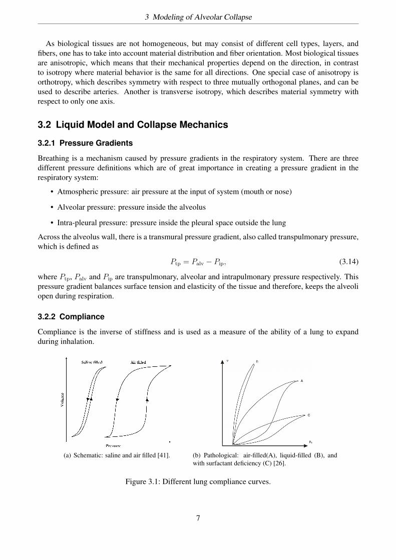
Compliance is the inverse of stiffness and is used as a measure of the ability of a lung to expandduring inhalation.
(a) Schematic: saline and air filled [41]. (b) Pathological: air-filled(A), liquid-filled (B), andwith surfactant deficiency (C) [26].
Figure 3.1: Different lung compliance curves.
7

3 Modeling of Alveolar Collapse
Analyzing the compliance curves of saline filled and air filled lungs, suggests that the hysteresiseffect due to the viscoelasticity of the lung tissue is negligible and surface tension plays a greater rolefor the overall compliance. In addition, different pulmonary diseases can effect the compliance curve(cf. Figure 3.1(b)). Therefore, the model of alveoli behavior highly depends on whether the lung is tobe considered normal and healthy or not and which species parameters are used (e.g. humans, pigs orrabbits).
3.2.3 Alveolar Surfactant and Surface Tension
Airways and alveoli are coated with a liquid layer, whose thickness is typically 2-4% of the airwaydiameter in healthy lungs [55] and up to 20% in diseased lungs [43]. The liquid layer in the airwaysis considered to be a two-layered, non-Newtonian fluid with viscoelastic [27] and shear-thinningcharacteristics and a considerable low yield stress [5]. However, alveolar surfactant is often modeledas a single layered, Newtonian fluid, primarily consisting of saltwater and surfactant [28]. Moredetails on the composition and mechanics of pulmonary surfactant can be found in [34].
One of the most important factors of alveolar stability and collapse is the surface tension of theliquid lining. The surface tension γ can be defined as
γ = ∆Π∆A, (3.15)
where ∆Π is the change in energy of the liquid and ∆A the change in the surface area. Duringthe respiratory cycle, this surface tension changes significantly. As the lung volume decreases, theliquid surface area declines and the concentration of surfactants increases, which results in a lowersurface tension. In normal, healthy lungs, pulmonary surfactant reduces the surface tension fromapproximately γ =72 mNm−1 to near zero [4] and reduces the Laplace pressure drop. This minimizesthe work during inspiration and prevents collapse during expiration. Capillary force, or Laplacepressure, describes the pressure difference that occurs across the curved interface of two fluids. TheYoung-Laplace equation describes this pressure with respect to the interface geometry, as
PLap = ∆P = γ ·( 1r1
+ 1r2
), (3.16)
with r1 and r2 as the principal radii of curvature and γ as the surface tension.
3.2.4 Collapse
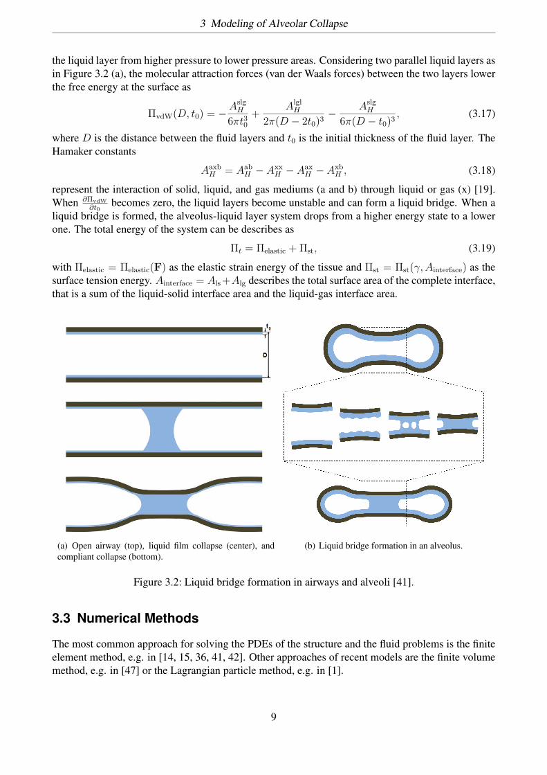
While collapse of airways occurs in healthy lungs as well [3], it poses a great threat for patients of lungdiseases and injuries, causing asphyxiation and death if not treated properly. In airways, three types ofcollapse can occur: complete collapse, film collapse (or capillary instability) and compliant collapse(or capillary-elastic instability) [24, 16, 17]. Complete collapse happens when the forces exerted onthe lung are so high that the airways are crushed. The other two collapse types are governed by thebehavior of the liquid lining. Film collapse occurs when the airways are too stiff and the surfacetension does not behave properly. Then, a liquid bridge can form and clog the airway. In this case,the Laplace pressure is not strong enough to deform the airway (cf. Fig. 3.2(a)).
Compliant collapse is more common in alveoli and describes the phenomenon where the tissueis elastic and the liquid bridge applies enough load to deform the alveolus walls. In both cases, thegoverning factor for meniscus formation is the Rayleigh instability. The Rayleigh instability describeshow the interface of two fluids becomes unstable under the force of surface tension and fluid flow of
8
3 Modeling of Alveolar Collapse
the liquid layer from higher pressure to lower pressure areas. Considering two parallel liquid layers asin Figure 3.2 (a), the molecular attraction forces (van der Waals forces) between the two layers lowerthe free energy at the surface as
ΠvdW(D, t0) = −AslgH
6πt30+ Algl
H
2π(D − 2t0)3 − AslgH
6π(D − t0)3 , (3.17)
where D is the distance between the fluid layers and t0 is the initial thickness of the fluid layer. TheHamaker constants
AaxbH = Aab
H − AxxH − Aax
H − AxbH , (3.18)
represent the interaction of solid, liquid, and gas mediums (a and b) through liquid or gas (x) [19].When ∂ΠvdW
∂t0becomes zero, the liquid layers become unstable and can form a liquid bridge. When a
liquid bridge is formed, the alveolus-liquid layer system drops from a higher energy state to a lowerone. The total energy of the system can be describes as
Πt = Πelastic + Πst, (3.19)
with Πelastic = Πelastic(F) as the elastic strain energy of the tissue and Πst = Πst(γ,Ainterface) as thesurface tension energy. Ainterface = Als +Alg describes the total surface area of the complete interface,that is a sum of the liquid-solid interface area and the liquid-gas interface area.
(a) Open airway (top), liquid film collapse (center), andcompliant collapse (bottom).
(b) Liquid bridge formation in an alveolus.
Figure 3.2: Liquid bridge formation in airways and alveoli [41].
3.3 Numerical Methods
The most common approach for solving the PDEs of the structure and the fluid problems is the finiteelement method, e.g. in [14, 15, 36, 41, 42]. Other approaches of recent models are the finite volumemethod, e.g. in [47] or the Lagrangian particle method, e.g. in [1].
9
3 Modeling of Alveolar Collapse
Geometry Representation
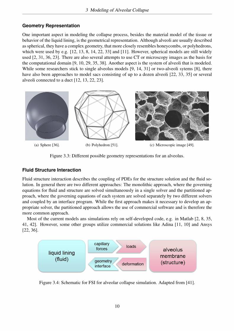
One important aspect in modeling the collapse process, besides the material model of the tissue orbehavior of the liquid lining, is the geometrical representation. Although alveoli are usually describedas spherical, they have a complex geometry, that more closely resembles honeycombs, or polyhedrons,which were used by e.g. [12, 13, 8, 14, 22, 33] and [11]. However, spherical models are still widelyused [2, 31, 36, 23]. There are also several attempts to use CT or microscopy images as the basis forthe computational domain [9, 10, 29, 35, 38]. Another aspect is the system of alveoli that is modeled.While some researchers stick to single alveolus models [9, 14, 31] or two-alveoli sytems [8], therehave also been approaches to model sacs consisting of up to a dozen alveoli [22, 33, 35] or severalalveoli connected to a duct [12, 13, 22, 23].
(a) Sphere [36]. (b) Polyhedron [51]. (c) Microscopic image [49].
Figure 3.3: Different possible geometry representations for an alveolus.
Fluid Structure Interaction
Fluid structure interaction describes the coupling of PDEs for the structure solution and the fluid so-lution. In general there are two different approaches: The monolithic approach, where the governingequations for fluid and structure are solved simultaneously in a single solver and the partitioned ap-proach, where the governing equations of each system are solved separately by two different solversand coupled by an interface program. While the first approach makes it necessary to develop an ap-propriate solver, the partitioned approach allows the use of commercial software and is therefore themore common approach.
Most of the current models ans simulations rely on self-developed code, e.g. in Matlab [2, 8, 35,41, 42]. However, some other groups utilize commercial solutions like Adina [11, 10] and Ansys[22, 36].
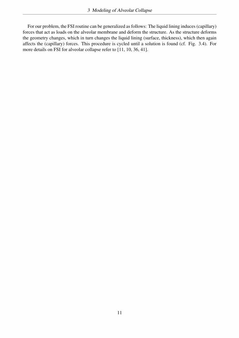
Figure 3.4: Schematic for FSI for alveolar collapse simulation. Adapted from [41].
10
3 Modeling of Alveolar Collapse
For our problem, the FSI routine can be generalized as follows: The liquid lining induces (capillary)forces that act as loads on the alveolar membrane and deform the structure. As the structure deformsthe geometry changes, which in turn changes the liquid lining (surface, thickness), which then againaffects the (capillary) forces. This procedure is cycled until a solution is found (cf. Fig. 3.4). Formore details on FSI for alveolar collapse refer to [11, 10, 36, 41].
11
4 Current Modeling Approaches
4.1 Review
This section introduces only a small selection of the most promising modeling approaches of the lastsix years. For more reviews of computational lung mechanics models focusing on surfactant behaviorrefer to [6, 28].
Current approaches in modeling lung behavior can generally be divided into four groups: collapsemodels including surfactant and tissue elasticity, collapse models without surfactant, lung tissue mod-els, and pulmonary surfactant models.
Andreassen et al. [2] presented one of the first models to combine tissue elasticity and dynamicsurfactant effects on alveolar stability. They assumed a spherical geometry for a single alveolus witha rigid ring as the opening to a duct. The model was implemented in MATLAB and used for dif-ferent sets of tissue and liquid configurations in order to understand the importance of tissue andfluid properties. Roobakhshan [41] also presented a combined model for a single, spherical alveolus,putting focus on the formation and rupture of liquid bridges in alveoli as a cause and effect of alveolarcollapse. The model was realized in MATLAB with plane strain and axisymmetric FEM. Anotherapproach was presented by Christley et al. [9], who utilized their own GPU algorithm to parallelizetheir collapse model, which incorporates tissue effects and surface tension. Bayesian inference wasused to quantify the uncertainty in model parameters for given experimental data. Fujioka et al. [14]presented another parallelized FEM approach to model the surfactant-induced parenchymal tether-ing of the alveoli. There, a model of over a thousand alveoli represented by truncated octahedrawas solved using displacement-based FEM. Lately, Chen et al [8] presented a micromechanical two-alveoli model including surfactant and surface tension effects and dynamic tissue response, backedby several experiments.
Wall, Rausch, and Wiechert [39, 38, 37, 48, 52, 51] have published several important works on themodeling of the alveolar geometry, tissue, and collapse, with special focus on strain and multiscalemodeling. Parameswaran et al. [33] modeled tissue destruction during collapse with different ideal-ized alveolar geometries, while Pidaparti et al. [36] compared FSI simulations with physiological andidealized alveolar models. Perlman and Wu [35] combined experimental and computational methodsin order to determine septal strain, stress and effective Young’s modulus.
Lastly, several groups focus on the detailed modeling of lung surfactant and its effects on breathing.Adami et. al [1] implemented a detailed multiphase surfactant model, including molecular dynamics,advection, and diffusion with coupled flow-field and surfactant dynamics. Another model was givenby Ganesan and Tobiska [15], who developed an ALE FEM for two-phase interface flow with solublesurfactants. The model was designed to solve evolution equations for the concentration of surfactantin the bulk phase and the interface, in addition to standard time-dependent Navier-Stokes equations.Saad et al. [45] proposed a dynamic surfactant model that incorporates adsorption and desorption, aswell as elasticity during compression and expansion.
12
4 Current Modeling Approaches
4.2 Drawbacks
While there has been a lot of progress in the last decade, there are still a number of drawbacks andlimitations. One general drawback is the validation. As there are still few experiments with humanlung tissue, reliable parameter sets for tissue and liquid are sparse and most numerical experimentscan not be verified properly. Therefore, most groups stick to parameter sets of animals. Anotherproblem is that most of the relevant mechanisms are coupled problems of fluid mechanics, tissuemechanics, biology and chemistry and thus, complete numerical models are not feasible. In addition,not all mechanisms concerning respiration and collapse are fully understood yet and therefore cannot be put into a reasonable mathematical description yet. While multi-scale approaches have alreadybeen realized, simulation of whole lung mechanics requires highly parallel algorithms and appropriatehardware.
Besides some simulations that use CT or microscopy images, most groups use simplified geome-try that highly affect the behavior of the alveoli, as the collapse mechanism depend on the area andthickness of the fluid layer and tissue, as well as the contact angle of the interfaces. In addition, thethicknesses of the media are not uniformly distributed inside the alveolus. Especially the liquid liningposes difficulties, as the surfactant and other components flow inside the interface, changing the localconcentration and therefore, the van-der-Waals forces and surface tension. Other common simplifi-cations are assumption of isotropic and elastic material behavior and Newtonian fluid behavior. Also,residual stresses and pre-stresses of lung tissue are usually neglected.
4.3 Example: Dynamic Liquid Membrane Model
As an example, we will discuss a dynamic model for the liquid layer in alveoli introduced by Roobakhshan[42]. The model consists of the compression-relaxation model (CRM) proposed by Saad et al. [45],which is used to extend the liquid membrane (LM) theory, proposed by R. A. Sauer [44], to accountfor dynamic surface tension.
Compression-Relaxation Model
The CR model introduces several important factors in the behavior of pulmonary surfactant, such assurface tension response to dynamic changes of surface area. This model incorporates several as-sumptions: First of all, there exists a maximum surfactant concentration to which the interface can bedynamically packed, resulting in a minimum surface tension γeq. Second, the transport of surfactantto the interface is adsorption limited, rather than diffusion limited. Third, the model considers fourfactors that affect the response of the dynamic surface tension: adsorption, described by the dynamicadsorption coefficient ka, relaxation (kr), elasticity during compression (εc), and elasticity duringexpansion (εe), defined by
k =
ka if γ ≥ γeq
kr if γ < γeq, (4.1)
ε =
εc if dsdt ≥ 0
εe if dsdt < 0
, (4.2)
where γeq is the equilibrium surface tension and s is the membrane area in the current configuration.Based on this model, an optimal lung surfactant should have fast adsorption rates, slower relaxation
13
4 Current Modeling Approaches
rates, and high elasticities. Combining these definitions, under the assumption that adsorption/desorp-tion and elasticity effects can happen simultaneously, gives us the time dependent change of surfacetension as
dγdt =
k(γeq − γ) + ε1s
dsdt if γ ≥ γmin
0 if γ < γmin. (4.3)
Liquid Membrane Theory
Sauer introduced a general computational formulation for liquid membranes [44]. It is applicable toboth, solid and liquid, membranes and addresses the quasi-static instability of the in-plane membranebehavior, as well as surface contact and contact angle.Here, the in-plane stress tensor can be written as
σ = σαβaα ⊗ aβ (4.4)
with
σαβ = γaαβ + σαβstab, (4.5)
where aαβ = aα · aβ is a component of the metric tensor and σαβstab is the stabilization parameter.As this formulation assumes surface tension to be fixed, we extend it to a dynamic liquid membrane(DLM) formulation to allow for changes in the surface tension. Considering 4.5 at time step tn givesus
(σαβ)n = γn(aαβ)n + (σαβstab)n. (4.6)
Now, both γn and (σαβstab)n depend on the history of deformation. Therefore, an evolution equationis needed to find surface tension changes from the quantities in the previous time step, in order todetermine γn.
Combined Formulation
In order to be able to use the compression-relaxation model, Eq. 4.3 has to be integrated, e.g. withthe implicit backward Euler method.
∆γδt
= 11 + k∆t
[γn−1 + kγeq∆t+ ε
(1 − sn−1
sn
)]. (4.7)
One can assume that the surface tension is constant over the whole membrane, i.e.
s =∫S
da =∫S0
JdA, (4.8)
with which Eq. 4.7 can be linearized in the current time step tn+1 as
∆γ = ε
1 + k∆tsn−1
(sn)2
∫S0
∆JdA. (4.9)
Another approach would be to assume a point-wise surface tension related to an infinitesimal areada = JdA that would give us
∆γ = ε
1 + k∆tJn−1
(Jn)2 ∆J. (4.10)
This can further be spatially discretized with the Galerkin finite element approach and solved with theNewton-Raphson method (see [42]).
14
4 Current Modeling Approaches
Results
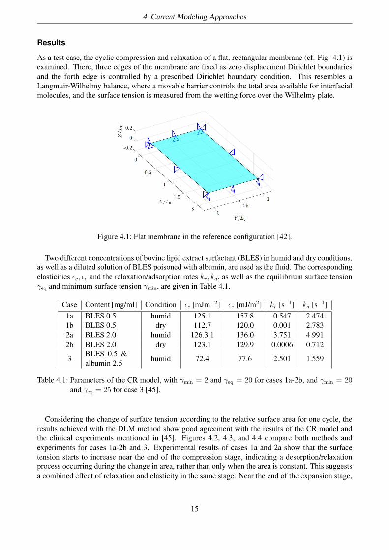
As a test case, the cyclic compression and relaxation of a flat, rectangular membrane (cf. Fig. 4.1) isexamined. There, three edges of the membrane are fixed as zero displacement Dirichlet boundariesand the forth edge is controlled by a prescribed Dirichlet boundary condition. This resembles aLangmuir-Wilhelmy balance, where a movable barrier controls the total area available for interfacialmolecules, and the surface tension is measured from the wetting force over the Wilhelmy plate.
Figure 4.1: Flat membrane in the reference configuration [42].
Two different concentrations of bovine lipid extract surfactant (BLES) in humid and dry conditions,as well as a diluted solution of BLES poisoned with albumin, are used as the fluid. The correspondingelasticities εc, εe and the relaxation/adsorption rates kr, ka, as well as the equilibrium surface tensionγeq and minimum surface tension γmin, are given in Table 4.1.
Case Content [mg/ml] Condition εc [mJm−2] εe [mJ/m2] kr [s−1] ka [s−1]1a BLES 0.5 humid 125.1 157.8 0.547 2.4741b BLES 0.5 dry 112.7 120.0 0.001 2.7832a BLES 2.0 humid 126.3.1 136.0 3.751 4.9912b BLES 2.0 dry 123.1 129.9 0.0006 0.712
3BLES 0.5 &albumin 2.5 humid 72.4 77.6 2.501 1.559
Table 4.1: Parameters of the CR model, with γmin = 2 and γeq = 20 for cases 1a-2b, and γmin = 20and γeq = 25 for case 3 [45].
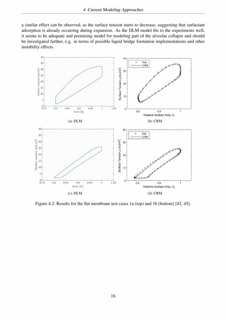
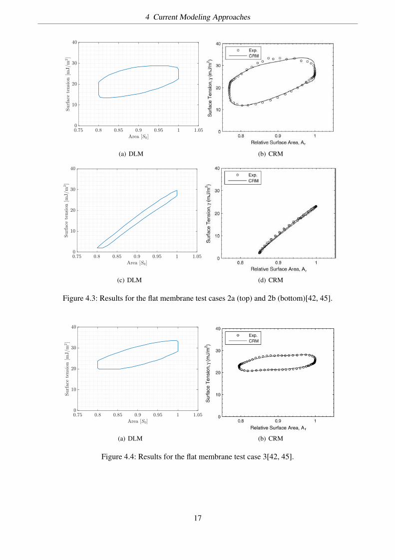
Considering the change of surface tension according to the relative surface area for one cycle, theresults achieved with the DLM method show good agreement with the results of the CR model andthe clinical experiments mentioned in [45]. Figures 4.2, 4.3, and 4.4 compare both methods andexperiments for cases 1a-2b and 3. Experimental results of cases 1a and 2a show that the surfacetension starts to increase near the end of the compression stage, indicating a desorption/relaxationprocess occurring during the change in area, rather than only when the area is constant. This suggestsa combined effect of relaxation and elasticity in the same stage. Near the end of the expansion stage,
15
4 Current Modeling Approaches
a similar effect can be observed, as the surface tension starts to decrease, suggesting that surfactantadsorption is already occurring during expansion. As the DLM model fits to the experiments well,it seems to be adequate and promising model for modeling part of the alveolar collapse and shouldbe investigated further, e.g. in terms of possible liquid bridge formation implementations and otherinstability effects.
Area [S0]0.75 0.8 0.85 0.9 0.95 1 1.05
Surfac
ete
nsion
[mJ/m
2]
0
5
10
15
20
25
30
35
40
(a) DLM (b) CRM
Area [S0]
0.75 0.8 0.85 0.9 0.95 1 1.05
Surface
tension
[mJ/m
2]
0
5
10
15
20
25
30
35
40
(c) DLM (d) CRM
Figure 4.2: Results for the flat membrane test cases 1a (top) and 1b (bottom) [42, 45].
16
4 Current Modeling Approaches
Area [S0]
0.75 0.8 0.85 0.9 0.95 1 1.05
Surface
tension
[mJ/m
2]
0
10
20
30
40
(a) DLM (b) CRM
Area [S0]
0.75 0.8 0.85 0.9 0.95 1 1.05
Surface
tension
[mJ/m
2]
0
10
20
30
40
(c) DLM (d) CRM
Figure 4.3: Results for the flat membrane test cases 2a (top) and 2b (bottom)[42, 45].
Area [S0]
0.75 0.8 0.85 0.9 0.95 1 1.05
Surface
tension
[mJ/m
2]
0
10
20
30
40
(a) DLM (b) CRM
Figure 4.4: Results for the flat membrane test case 3[42, 45].
17
Bibliography
[1] S. Adami, X.Y. Hu, and N.A. Adams. A conservative sph method for surfactant dynamics.Journal of Computational Physics, 229(5):1909–1926, 2010.
[2] S. Andreassen, K.L. Steimle, M.L. Mogensen, J.B. de la Serna, S. Rees, and D.S. Karbing.The effect of tissue elastic properties and surfactant on alveolar stability. Journal of appliedphysiology, 109(5):1369–1377, 2010.
[3] N.R. Anthonisen, J. Danson, P.C. Robertson, and W.R.D. Ross. Airway closure as a function ofage. Respiration physiology, 8(1):58–65, 1969.
[4] H. Bachofen and S. Schürch. Alveolar surface forces and lung architecture. Comparative Bio-chemistry and Physiology Part A: Molecular & Integrative Physiology, 129(1):183–193, 2001.
[5] P.J. Basser, T.A. McMahon, and P. Griffith. The mechanism of mucus clearance in cough.Journal of biomechanical engineering, 111(4):288–297, 1989.
[6] J.H.T. Bates, B.J. Smith, and G.B. Allen. Computational models of ventilator induced lunginjury and surfactant dysfunction. Drug Discovery Today: Disease Models, 15:17–22, 2015.
[7] The Southwest Environmental Health Sciences Center. Cross section through alveoli.
[8] Z. Chen, Y. Chen, and Z. Hu. A micromechanical model for estimating alveolar wall strainin mechanically ventilated edematous lungs. Journal of Applied Physiology, 117(6):586–592,2014.
[9] S. Christley, B. Emr, A. Ghosh, J. Satalin, L. Gatto, Y. Vodovotz, G.F. Niemann, and G. An.Bayesian inference of the lung alveolar spatial model for the identification of alveolar mechanicsassociated with acute respiratory distress syndrome. Physical biology, 10(3):036008, 2013.
[10] H.L. Dailey, L.M. Ricles, H.C. Yalcin, and S.N. Ghadiali. Image-based finite element model-ing of alveolar epithelial cell injury during airway reopening. Journal of Applied Physiology,106(1):221–232, 2009.
[11] H.L. Dailey, H.C. Yalcin, and S.N. Ghadiali. Fluid-structure modeling of flow-induced alveolarepithelial cell deformation. Computers & structures, 85(11):1066–1071, 2007.
[12] E. Denny and R.C. Schroter. The mechanical behavior of a mammalian lung alveolar ductmodel. Journal of biomechanical engineering, 117(3):254–261, 1995.
[13] E. Denny and R.C. Schroter. Viscoelastic behavior of a lung alveolar duct model. Journal ofbiomechanical engineering, 122(2):143–151, 2000.
[14] H. Fujioka, D. Halpern, and D.P. Gaver. A model of surfactant-induced surface tension effectson the parenchymal tethering of pulmonary airways. Journal of biomechanics, 46(2):319–328,2013.
I
Bibliography
[15] S. Ganesan and L. Tobiska. Arbitrary lagrangian–eulerian finite-element method for com-putation of two-phase flows with soluble surfactants. Journal of Computational Physics,231(9):3685–3702, 2012.
[16] D. Halpern and J.B. Grotberg. Fluid-elastic instabilities of liquid-lined flexible tubes. Journalof Fluid Mechanics, 244:615–632, 1992.
[17] D. Halpern and J.B. Grotberg. Surfactant effects on fluid-elastic instabilities of liquid-linedflexible tubes: a model of airway closure. Journal of biomechanical engineering, 115(3):271–277, 1993.
[18] J.E. Hansen, E.P. Ampaya, G.H. Bryant, and J.J Navin. Branching pattern of airways and airspaces of a single human terminal bronchiole. Journal of applied physiology, 38(6):983–989,1975.
[19] Hamaker H.C. The london-van der waals attraction between spherical particles. physica,4(10):1058–1072, 1937.
[20] G.A. Holzapfel. Nonlinear solid mechanics, volume 24. Wiley Chichester, 2000.
[21] Howshealth. Atelectasis: definition, causes, and treatment.
[22] E.M. Harding Jr. and R.J. Robinson. Flow in a terminal alveolar sac model with expanding wallsusing computational fluid dynamics. Inhalation toxicology, 22(8):669–678, 2010.
[23] K-Schirrmann, M. Mertens, U. Kertzscher, W.M. Kuebler, and K. Affeld. Theoretical modelingof the interaction between alveoli during inflation and deflation in normal and diseased lungs.Journal of biomechanics, 43(6):1202–1207, 2010.
[24] R.D. Kamm and R.C. Schroter. Is airway closure caused by a liquid film instability? Respirationphysiology, 75(2):141–156, 1989.
[25] S.S. Kenneth and M.P. Carol. Anatomy and physiology: The unity of form and function, 2006.
[26] M. Klaas and W. Schroeder. Bilogische und medizinische stroemungstechnik i. Lecture script.
[27] S.K. Lai, Y. Wang, D. Wirtz, and J. Hanes. Micro-and macrorheology of mucus. Advanced drugdelivery reviews, 61(2):86–100, 2009.
[28] R. Levy, D.B. Hill, M.G. Forest, and J.B. Grotberg. Pulmonary fluid flow challenges for ex-perimental and mathematical modeling. Integrative and comparative biology, 54(6):985–1000,2014.
[29] H.D. Litzlbauer, C. Neuhaeuser, A. Moell, S. Greschus, A. Breithecker, F.E. Franke, W. Kum-mer, and W.S. Rau. Three-dimensional imaging and morphometric analysis of alveolar tissuefrom microfocal x-ray-computed tomography. American Journal of Physiology-Lung Cellularand Molecular Physiology, 291(3):L535–L545, 2006.
[30] R.R. Mercer, M.L. Russell, and J.D. Crapo. Alveolar septal structure in different species. Jour-nal of Applied Physiology, 77(3):1060–1066, 1994.
II
Bibliography
[31] M. Muradoglu and G. Tryggvason. A front-tracking method for computation of interfacial flowswith soluble surfactants. Journal of computational physics, 227(4):2238–2262, 2008.
[32] M. Ochs, J.R. Nyengaard, A. Jung, L. Knudsen, M. Voigt, T. Wahlers, J. Richter, and H.J.G.Gundersen. The number of alveoli in the human lung. American journal of respiratory andcritical care medicine, 169(1):120–124, 2004.
[33] H. Parameswaran, A. Majumdar, and B. Suki. Linking microscopic spatial patterns of tissuedestruction in emphysema to macroscopic decline in stiffness using a 3d computational model.PLoS Comput Biol, 7(4):e1001125, 2011.
[34] E. Parra and J. Pérez-Gil. Composition, structure and mechanical properties define performanceof pulmonary surfactant membranes and films. Chemistry and physics of lipids, 185:153–175,2015.
[35] C.E. Perlman and Y. Wu. In situ determination of alveolar septal strain, stress and effectiveyoung’s modulus: an experimental/computational approach. American Journal of Physiology-Lung Cellular and Molecular Physiology, 307(4):L302–L310, 2014.
[36] R.M. Pidaparti, M. Burnette, R.L. Heise, and A. Reynolds. Analysis for stress environment inthe alveolar sac model. Journal of biomedical science and engineering, 6(9):901, 2013.
[37] S.M.K. Rausch. Computational and experimental Modeling of Lung parenchyma. PhD thesis,Technische Universitaet Muenchen, 2015.
[38] S.M.K. Rausch, D. Haberthür, M. Stampanoni, J.C. Schittny, and W.A. Wall. Local straindistribution in real three-dimensional alveolar geometries. Annals of biomedical engineering,39(11):2835–2843, 2011.
[39] S.M.K. Rausch, C. Martin, P.B. Bornemann, S. Uhlig, and W.A. Wall. Material model of lungparenchyma based on living precision-cut lung slice testing. Journal of the mechanical behaviorof biomedical materials, 4(4):583–592, 2011.
[40] M. Roberts, M. Reiss, and G. Monger. Gaseous exchange. Advanced Biology, page 167, 2000.
[41] F. Roobakhshan. Computational Modeling of Lung Failure at the Alveoli Level. Master thesis,RWTH Aachen University, Fakultät für Maschinenwesen, 2011.
[42] F. Roobakhshan and R.A. Sauer. Membrane fe analysis of pulmonary surface active agents.European Journal of Applied Mathematics, 20(4):363–397, 2016.
[43] M.A. Sackner and C.S. Kim. Phasic flow mechanisms of mucus clearance. European journal ofrespiratory diseases. Supplement, 153:159–164, 1986.
[44] R.A. Sauer. Stabilized finite element formulations for liquid membranes and their application todroplet contact. International Journal for Numerical Methods in Fluids, 75(7):519–545, 2014.
[45] A.W. Neumann S.M.I Saad and E.J. Acosta. A dynamic compression–relaxation model for lungsurfactants. Colloids and Surfaces A: Physicochemical and Engineering Aspects, 354(1):34–44,2010.
[46] Sphweb. Pulmonary alveolus.
III
Bibliography
[47] C.F. Tai, S. Bian, D. Halpern, Y. Zheng, M. Filoche, and J.B. Grotberg. Numerical study of flowfields in an airway closure model. Journal of Fluid Mechanics, 677:483–502, 2011.
[48] W.A. Wall, L. Wiechert, A. Comerford, and S.M.K. Rausch. Towards a comprehensive com-putational model for the respiratory system. International Journal for Numerical Methods inBiomedical Engineering, 26(7):807–827, 2010.
[49] E.R. Weibel. What makes a good lung. Swiss Med Wkly, 139(27-28):375–386, 2009.
[50] E.R. Weibel and D.M. Gomez. Architecture of the human lung use of quantitative meth-ods establishes fundamental relations between size and number of lung structures. Science,137(3530):577–585, 1962.
[51] L. Wiechert. Computational Modeling of Multi-Field and Multi-Scale Phenomena in Respira-tory Mechanics. PhD thesis, Technische Universitaet Muenchen, 2011.
[52] L. Wiechert, A. Comerford, S.M.K. Rausch, and W.A. Wall. Advanced multi-scale modelling ofthe respiratory system. In Fundamental Medical and Engineering Investigations on ProtectiveArtificial Respiration, pages 1–32. Springer, 2011.
[53] Wikipedia. Pulmonary alveolus.
[54] P. Wriggers. Nonlinear finite element methods. Springer Science & Business Media, 2008.
[55] D. Yager, T. Cloutier, H. Feldman, J. Bastacky, J.M. Drazen, and R.D. Kamm. Airway surfaceliquid thickness as a function of lung volume in small airways of the guinea pig. Journal ofApplied Physiology, 77(5):2333–2340, 1994.
IV