amphenol · cable length (in whole metres) cable specification omt for pan 6421 (711-6421) a –...
TRANSCRIPT
AmphenolAmphenolAmphenolAmphenol
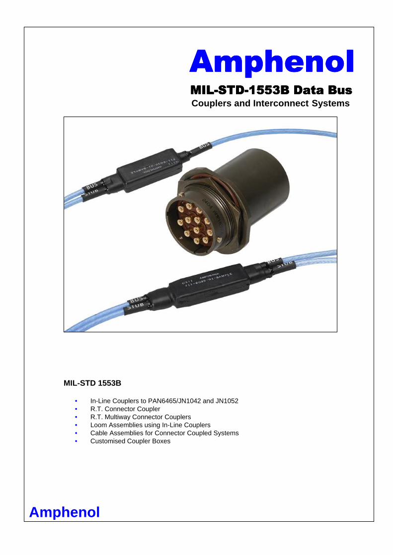
MILMILMILMIL----STDSTDSTDSTD----1553B Data Bus1553B Data Bus1553B Data Bus1553B Data Bus Couplers and Interconnect Systems
MIL-STD 1553B
• In-Line Couplers to PAN6465/JN1042 and JN1052 • R.T. Connector Coupler • R.T. Multiway Connector Couplers • Loom Assemblies using In-Line Couplers • Cable Assemblies for Connector Coupled Systems • Customised Coupler Boxes
Amphenol

Description
A wide range of R.T. Couplers providing transformer coupling between MIL-STD-1553 Def Stan 00-18 (Part 2) Data Bus and Single, Dual or Multiple Remote Terminals (RT). Coupling transformers and associated isolation resistors are contained in a continuous shield providing electro-magnetic and environmental shielding. Transformers used in the range of R.T. Couplers are fully compliant with the requirement of MIL-STD-1553B clauses 4.5.1.5.1.1. to 4.5.1.5.1.1.3, in respect of turns ratio, input impedance, waveform integrity and common mode rejection.
Transformers used are compatible with currently available transceivers and meet all
electrical requirements of Manchester Series II serial bi-phase data transmission, and are designed to meet the requirements of MIL-T-21038 Grades 5 and 7/Class S/Life X.
Amphenol provide a wide range of R.T. Couplers designed to meet the requirements of a large number of users. R.T. Couplers fitted with flying leads (e.g. 711-6116) are used where space and weight restrictions are critical, such as aircraft. R.T. Can Couplers are used in panels and control boxes where multiple couplers are required in a small area.
Electrical Characteristics
Transformer turns ratio 1:√2. Series resistors 57ohms. Characteristic Impedance 77.05ohms. R.T. Coupler units with alternative transformer characteristics to suit particular bus impedances are available. The wide range of R.T. Couplers are compliant with MIL-STD-1553B clauses 4.5.1.5.1.2 and 4.5.1.5.1.4 in respect of fault isolation, cable coupling, shielding coverage, signal waveform, frequency and modulation. Operating Conditions
Ambient temperature range –55oC to 125oC (3Kohms minimum impedance at 55oC)
R.T. Couplers – connector coupling are used in prototype or test harnesses where adaptability is required but space and weight are not major considerations. The ruggedised R.T. coupler has been designed for military applications such as fighting vehicles where robustness and intermateability with military connectors are required. The coupler mates with 38999 Series III and utilises Amphenol Ltds size 8 data bus contacts. Amphenol Ltd provides a full design and manufacturing facility and can supply inter-connection systems for specialised customer requirements
Applicable Specifications R.T. Couplers are designed to conform to the following documents:
- MIL-STD-1553B - Material Time Division Command / Response Multiplexed Data Bus - MIL-STD-4546 - Standard General Requirements for Electronic Equipment - MIL-STD-810C – Environmental Test Methods - MIL-E-6051 – Electromagnetic Compatibility Requirements Defence Standard 18 (Part 2) – Avionics Data Transmission Interface System
- BS9522 F0042 Single Way – Data Bus Connectors - BS9522 F0043 Multi Way – Data Bus Connectors
- 2 -

In Line Couplers Single Way Data Bus Micro Coupler – 711-6030-XX / JN 1 042-XX Two Way Data Bus Micro Coupler – 711-6025-XX
Features Include:
• The 711-6025-XX and 711-6030-XX are designed for use on Eurofighter Typhoon as JN1052 and JN1042 respectively
• Complies with the requirements of MIL-STD-1553B • Fully environmentally sealed • Fully adaptable using Amphenol Ltd’s range of 711 Series connectors • Can be manufactured into complex multi-coupler looms up to 32 stub • Lightweight and compact – ideal for use in aircraft systems • Full fluid resistance to aviation fuels, hydraulic and brake fluids, lubricants and ancillary fluids • EMI screened • Eurofighter JN Approved
CABLE LENGTH
3.346 MAX
(84.99)
.394 MAX
(10.01)
.591
MA
X
(15.
01)
- 3 -

711 Series Multiway R.T. Can Couplers Multiway Flange Mtg. Coupler Receptacle – 02AC/JN11 68BC
Shell Size
Bi ±0.38
(±0.015) C Sq Max
D1 dia. ±0.05
(±.002)
D2 dia. ±0.13
(±.005)
E ±0.41
(±.016) F Max M1 dia.
Max P Max. V Min. W dia. ±0.13
(±.005)
X Sq. ±0.13
(±.005) 11.33 28.98 3.18 3.25 1.57 49.00 22.25 2.21 33.15 25.12 23.01
14 (0.446) (1.141) (0.125) (0.128) (0.062) (1.929) (0.876) (0.087) (1.305) (0.989) (0.906) 11.33 31.34 3.18 3.25 1.57 57.00 25.43 2.21 37.85 28.27 24.61
16 (0.446) (1.234) (0.125) (0.128) (0.062) (2.244) (1.001) (0.087) (1.490) (1.113) (0.969) 11.33 33.73 3.18 3.25 1.57 60.00 28.60 2.21 40.64 31.45 26.97
18 (0.446) (1.328) (0.125) (0.128) (0.062) (2.362) (1.126) (0.087) (1.600) (1.238) (1.062) 14.50 36.91 3.18 3.25 2.39 64.00 31.78 5.38 43.81 34.62 29.36
20 (0.571) (1.453) (0.125) (0.128) (0.094) (2.520) (1.251) (0.212) (1.725) (1.363) (1.156) 14.50 40.08 3.18 3.25 2.39 64.00 34.95 5.38 46.61 37.80 31.75
22 (0.571) (1.578) (0.125) (0.128) (0.094) (2.520) (1.376) (0.212) (1.835) (1.488) (1.250) 15.37 43.26 3.86 3.94 2.39 64.50 38.13 5.38 49.78 41.02 34.92
24 (0.605) (1.703) (0.152) (0.155) (0.094) (2.539) (1.501) (0.212) (1.960) (1.615) (1.375)
Multiway Single Hole Mtg. Coupler Receptacle – 03AC/ JN1168AC
P Panel Thickness Shell Size B Max. D Sq. E Max. F Max. K A/F
Max. M Max.
dia. Max. Min. V Min.
W dia ±0.13
(±.005)
Z1 ±0.13
(±.005)
Z1 ±0.13
(±.005) 17.96 35.33 2.87 49.00 30.61 22.25 4.75 1.57 36.82 25.65 23.80 24.08
14 (0.707) (1.391) (0.113) (1.929) (1.205) (0.876) (0.187) (0.062) (1.430) (1.010) (0.937) (0.948) 17.96 38.51 2.87 57.00 33.76 25.43 4.75 1.57 39.88 28.83 26.95 27.23
16 (0.707) (1.516) (0.113) (2.244) (1.329) (1.001) (0.187) (0.062) (1.570) (1.135) (1.061) (1.072) 17.96 41.68 2.87 66.50 36.96 28.60 4.75 1.57 43.69 32.00 30.12 30.40
18 (0.707) (1.641) (0.113) (2.618) (1.455) (1.126) (0.187) (0.062) (1.720) (1.260) (1.186) (1.197) 19.61 46.43 3.76 69.00 40.11 31.78 6.35 1.57 47.37 35.18 33.30 33.58
20 (0.772) (1.828) (0.148) (2.716) (1.579) (1.251) (0.250) (0.062) (1.865) (1.385) (1.311) (1.322) 19.61 49.63 3.76 69.00 43.31 34.95 6.35 1.57 50.93 38.35 36.47 36.75
22 (0.772) (1.954) (0.148) (2.716) (1.705) (1.376) (0.250) (0.062) (2.005) (1.510) (1.436) (1.447) 19.61 52.78 3.76 69.00 46.46 38.13 5.56 1.57 54.61 41.53 39.65 39.93
24 (0.772) (2.078) (3.76) (2.716) (1.829) (1.501) (0.219) (0.062) (2.150) (1.635) (1.561) (1.572)
F
M1 DIA
E
P2 PANEL THICKNESS
P1 PANEL THICKNESS
C SQ
d1 DIA
X SQ
V
D2 DIA W
PANEL PIERCING
E B
M DIA Z1 FLAT
K A/F
D SQ
W DIA
Z2
V
PANEL PIERCING
- 4 -

Multiway Insert Circuit Configurations Lettering of Inserts shown here corresponds to view s of Front (Mating) Surface of Pin Inserts
Technical Data Standard product available as shown. Planforms up to 24-12 can be supplied to customer specification. 711 Series R.T. Can Couplers have been designed to give a larger coupler capability in a small package. They utilise the design concepts of Amphenol Ltd’s widely accepted and proven 711 series Multiway connectors. Features Include:
• Qualified to Eurofighter Specification J64.520 (JN1168) • Complies with the requirements of MIL-STD-1553B • Utilises ceramic substrate technology • Compact design • Fully potted for sealing purposes and rigidity • Box or panel mounted • Intermateable with Amphenol Ltd 711 Multiway connectors • EMI screened
- 5 -
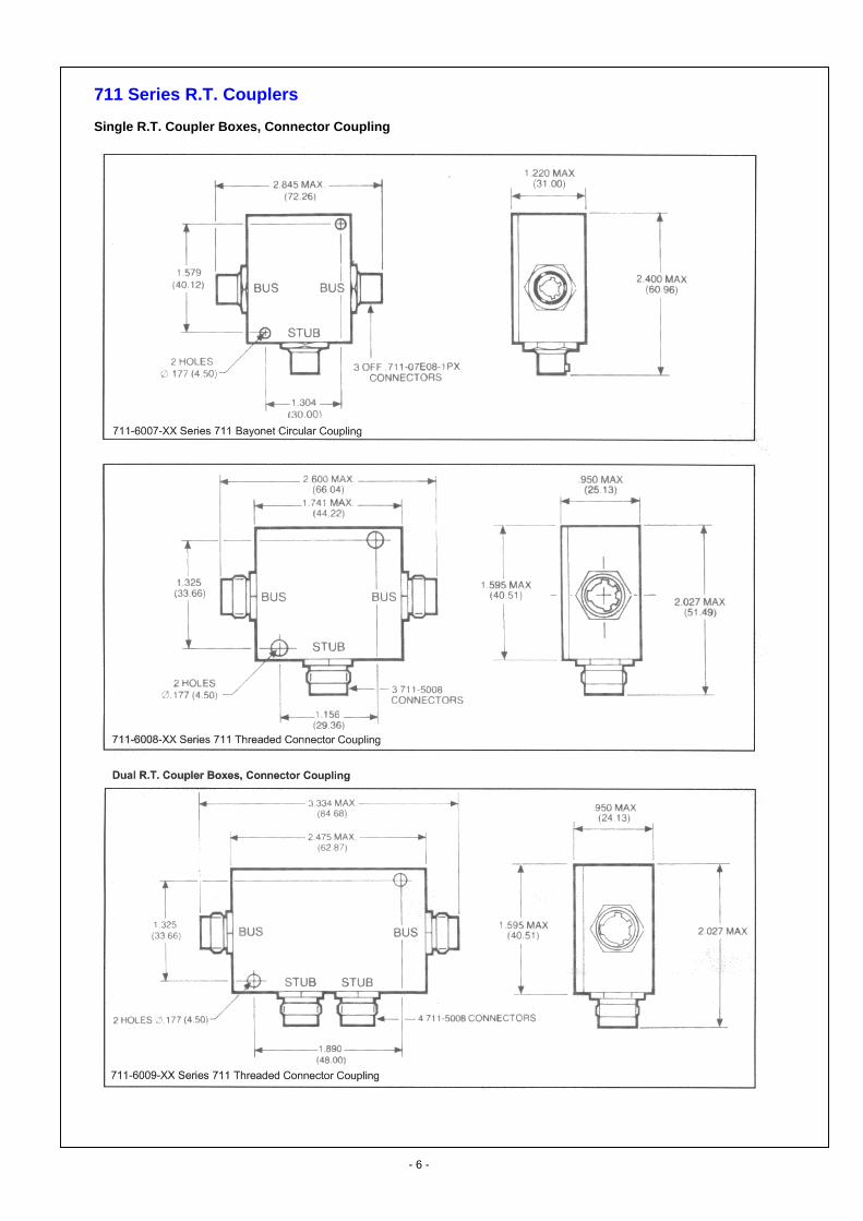
711 Series R.T. Couplers Single R.T. Coupler Boxes, Connector Coupling
- 6 -
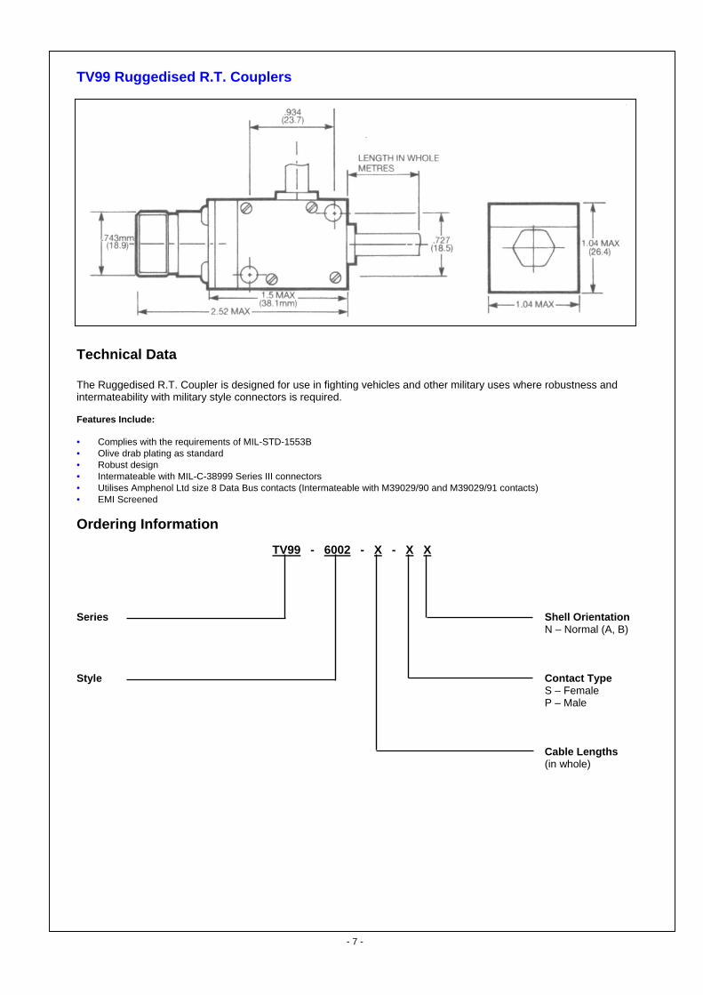
TV99 Ruggedised R.T. Couplers
Technical Data The Ruggedised R.T. Coupler is designed for use in fighting vehicles and other military uses where robustness and intermateability with military style connectors is required. Features Include: • Complies with the requirements of MIL-STD-1553B • Olive drab plating as standard • Robust design • Intermateable with MIL-C-38999 Series III connectors • Utilises Amphenol Ltd size 8 Data Bus contacts (Intermateable with M39029/90 and M39029/91 contacts) • EMI Screened
Ordering Information
TV99 - 6002 - X - X X
Series Shell Orientation N – Normal (A, B) Style Contact Type S – Female P – Male Cable Lengths (in whole)
- 7 -

711 Series R.T. Couplers R.T. Couplers, Flying Lead Termination Technical Data The 711-6000-X and 711-6001-X R.T. Couplers conform to the requirements of MIL-STD-1553B. Features Include: • Fully adaptable using Amphenol Ltd range of 711 Series connectors • Box or wall mounting • Robust design • EMI Screened
Ordering Information
711-600X- A Cable Length (in whole metres) Cable Specification OMT for PAN 6421 (711-6421) A – 10613 B – EPD 29474D
711-6000-X Single R.T. Coupler Box
711-6001-X Dual R.T. Coupler Box
- 8 -

711/715 Series R.T. Couplers Multi R.T. Coupler Boxes, Connector Coupling Technical Data Amphenol Ltd produce a range of connector coupling R.T. boxes. These range from single R.T. Couplers to 5-Stub bus terminating devices. Features Include • Complies to the requirements of MIL-STD-1553B. • Wall mounted, robust design. • Adaptable for use in prototype and test looms. • Fully intermateable with Amphenol Ltd 711 series single or multiway connectors • Fully potted for sealing purposes and rigidity
In Line Mechanical Splice
Features Include: Ordering Information: • Provides a low cost repair solution Part Number 711-5034 (462) • Utilises standard #10 Data Bus crimp contacts • Uses standard tooling • Environmentally Sealed
1.900 NOMINAL (48.26)
7/16 A/F
- 9 -
711-6010-X Multi Stub R.T. Couplers For deviation code (X) and information regarding applicable connectors, please consult Amphenol Ltd
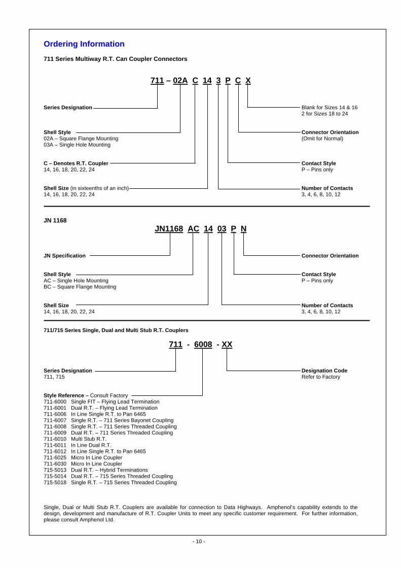
Ordering Information 711 Series Multiway R.T. Can Coupler Connectors
711 – 02A C 14 3 P C X
Series Designation Blank for Sizes 14 & 16 2 for Sizes 18 to 24 Shell Style Connector Orientation 02A – Square Flange Mounting (Omit for Normal) 03A – Single Hole Mounting C – Denotes R.T. Coupler Contact Style 14, 16, 18, 20, 22, 24 P – Pins only Shell Size (in sixteenths of an inch) Number of Contacts 14, 16, 18, 20, 22, 24 3, 4, 6, 8, 10, 12 JN 1168
JN1168 AC 14 03 P N
JN Specification Connector Orientation Shell Style Contact Style AC – Single Hole Mounting P – Pins only BC – Square Flange Mounting Shell Size Number of Contacts 14, 16, 18, 20, 22, 24 3, 4, 6, 8, 10, 12 711/715 Series Single, Dual and Multi Stub R.T. Cou plers
711 - 6008 - XX Series Designation Designation Code 711, 715 Refer to Factory Style Reference – Consult Factory 711-6000 Single FIT – Flying Lead Termination 711-6001 Dual R.T. – Flying Lead Termination 711-6006 In Line Single R.T. to Pan 6465 711-6007 Single R.T. – 711 Series Bayonet Coupling 711-6008 Single R.T. – 711 Series Threaded Coupling 711-6009 Dual R.T. – 711 Series Threaded Coupling 711-6010 Multi Stub R.T. 711-6011 In Line Dual R.T. 711-6012 In Line Single R.T. to Pan 6465 711-6025 Micro In Line Coupler 711-6030 Micro In Line Coupler 715-5013 Dual R.T. – Hybrid Terminations 715-5014 Dual R.T. – 715 Series Threaded Coupling 715-5018 Single R.T. – 715 Series Threaded Coupling Single, Dual or Multi Stub R.T. Couplers are available for connection to Data Highways. Amphenol’s capability extends to the design, development and manufacture of R.T. Coupler Units to meet any specific customer requirement. For further information, please consult Amphenol Ltd.
- 10 -

Notice: Products are sold subject to Amphenol’s conditions of sale (“the standard conditions”). All specifications and statements contained herein are believed to be correct at the time of printing but no representation or warranty, express or implied, is given as to any specification or statement contained herein. Product specifications including performance characteristics are typical only and subject to deviation. Specifications are also subject to change without notice. Users should not assume that all safety measures are indicated or that other measures may not be required. No representation or warranty, express or implied, is given that any use of products (including any stated or suggested use) does not infringe any patent, registered design or other third party rights and no stated or suggested use of products can be taken to recommend any such infringement.
Amphenol Thanet Way, Whitstable, Kent. CT5 3JF Tel: 01227 773200 Fax: 01227 276571