alu loadbalancingsolution emcta v5.1
DESCRIPTION
ALU LoadBalancingSolution EMCTA v5.1TRANSCRIPT
Alcatel-Lucent
End-To-End
Alcatel-Lucent solution for load balancing
between 2G, 3G, LTE and Wifi
JULY 2011
V5.1
E N D - T O - E N D L T E S O L U T I O N S � � � � � � � � � � � � � � � � � � � � � � � � � � � � � � � � � � � � � � � � � � � � � � � � � � � � � � � � � � � � � � � � � � � � � � � � � � � � � � � � � � � � � � � � � �
Load balancing solution between LTE, 2G, 3G.
Alcatel-Lucent Proprietary and Confidential © 2011 All Rights Reserved 2
CONTENTS
1 INTRODUCTION ................................................................................................ 5
2 STANDARDS PERSPECTIVE ................................................................................... 6
2.1 RADIO LOAD BALANCING ........................................................................................ 6
2.2 RADIO LOAD BALANCING IN 3GPP RELEASE 9 .................................................................... 8
3 ALCATEL-LUCENT SOLUTION FOR LOAD BALANCING ................................................... 9
3.1 THE EMCTA FUNCTION .......................................................................................10
3.1.1 Criteria used by eMCTA for the definition of the operator strategy for service allocation on
available carriers .............................................................................................11
3.1.2 Criteria used by eMCTA related to the UE context ..........................................13
3.2 LOAD BALANCING BY ADAPTING MOBILITY PARAMETERS ...........................................................14
3.3 TRAFFIC LOAD BALANCING BETWEEN RATS .....................................................................16
3.4 LOAD BALANCING ON THE WDCMA METRO CELL ...............................................................17
3.4.1 WCDMA Metro Cell Overload ....................................................................17
3.4.2 Reselection from WCMA to LTE and SIB 19 Support..........................................18
3.4.3 Load Measurements of the WCDMA Macro ....................................................18
3.4.4 Load Measurements of the WCDMA Metro ....................................................18
4 ALCATEL-LUCENT WLAN OFFLOAD SOLUTION ......................................................... 19
5 ALCATEL-LUCENT KEY DIFFERENTIATORS .............................................................. 20
6 CONCLUSION ................................................................................................. 21
7 ACRONYMS .................................................................................................... 22
Load balancing solution between LTE, 2G, 3G.
Alcatel-Lucent Proprietary and Confidential © 2011 All Rights Reserved 3
LIST OF FIGURES
Figure 1: Load Indication ...................................................................................................... 7
Figure 2: Resource Status Reporting Initiation .............................................................................. 8
Figure 3: Load information exchange between RAT of different types ................................................. 9
Figure 4: The eMCTA function ................................................................................................ 10
Figure 5: Examples of eMCTA applications based on load, priority and services ...................................... 14
Figure 6: Load balancing by adapting handover parameters ............................................................. 15
Load balancing solution between LTE, 2G, 3G.
Alcatel-Lucent Proprietary and Confidential © 2011 All Rights Reserved 4
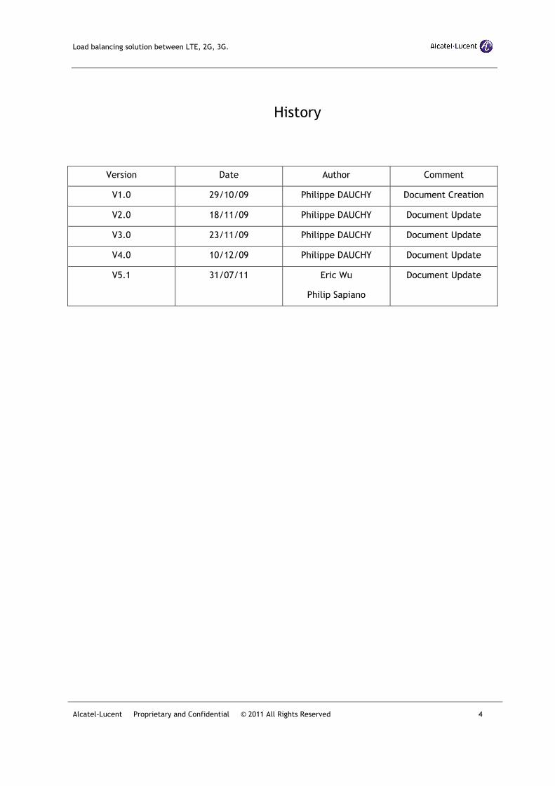
History
Version Date Author Comment
V1.0 29/10/09 Philippe DAUCHY Document Creation
V2.0 18/11/09 Philippe DAUCHY Document Update
V3.0 23/11/09 Philippe DAUCHY Document Update
V4.0 10/12/09 Philippe DAUCHY Document Update
V5.1 31/07/11 Eric Wu
Philip Sapiano
Document Update
Load balancing solution between LTE, 2G, 3G.
Alcatel-Lucent Proprietary and Confidential © 2011 All Rights Reserved 5
1 INTRODUCTION
LTE is being deployed in the areas where traffic demand justifies the investments. Such areas
are typically already served by 2G and 3G networks. Therefore the result will be a multilayer
network composed of both 2G, 3G and LTE layers, including traditional macro cells as well as
small cells (Metro Cells).
The challenge in a multilayer network is to intelligently distribute the load on the different
available layers to optimize the network resource usage while guaranteeing the quality of
service (QoS) of the different active connections and minimizing unnecessary redirections
between layers.
This is the task of a load balancing solution which aims at handling uneven distribution of the
traffic load over multiple cells. The purpose of load balancing is thus to influence the load
distribution in such a manner that radio resources remain highly utilized and the QoS of in-
progress sessions is maintained to the greatest extent possible and call dropping probabilities
are kept sufficiently small. Load balancing algorithms may result in handover or cell
reselection decisions with the purpose of redistributing traffic from highly loaded cells to
under-utilized cells.
Alcatel-Lucent believes that load balancing will play a key role in optimizing radio network
resources and will contribute to a high end user experience while retaining high revenue for
the service provider. Alcatel-Lucent is one of the top three leaders at the 3GPP
standardization body on load balancing related topics.
This document describes the Alcatel-Lucent load balancing solution for optimizing the system
capacity of a multilayer network composed of 2G, 3G and LTE cells. It is structured as follows:
o Section 2 presents the 3GPP mechanisms relevant for a load balancing solution.
o Section 3 presents the Alcatel-Lucent load balancing solution.
o Section 4 presents Alcatel-Lucent’s WLAN offload solution
o Section 5 presents the key differentiators of the Alcatel-Lucent load balancing
solution and
o Section 6 concludes the document.
Features related to the load balancing solution are listed in Section Error! Reference source
not found. “Annex”.
Load balancing solution between LTE, 2G, 3G.
Alcatel-Lucent Proprietary and Confidential © 2011 All Rights Reserved 6
2 STANDARDS PERSPECTIVE
3GPP standards applicable to the load balancing are listed in the table below:
Standard Specification Description
TS 23.401 General Packet Radio Service (GPRS) enhancements for Evolved Universal
Terrestrial Radio Access Network (E-UTRAN) access (Release 9)
TS 36.423 Evolved Universal Terrestrial Radio Access Network (E-UTRAN); X2 application
protocol (X2AP) (Release 9)
TR 36.902 Evolved Universal Terrestrial Radio Access Network (E-UTRAN); Self-configuring
and self-optimizing use cases and solutions (Release 9)
3GPP release 8 introduced several procedures allowing load balancing between network
elements of the LTE networks:
o Between eNodeB two procedures are defined to exchange cell load information:
“Load Indication” and “Resource Status Reporting Initiation”.
o Between eNodeB and MME the standard defines the mechanisms allowing to direct a
UE to an appropriate MME of a given MME pool area to achieve load balancing
between MMEs. This is achieved by setting a weight factor for each MME of the MME
pool area, such that the probability of the eNodeB selecting an MME is proportional to
its weight factor. The weight factor is typically set according to the capacity of an
MME node relative to other MME nodes.
o Load balancing between available SGWs can also be performed by the MME when
selecting a given SGW to serve the UE.
3GPP release 9 adds more sophisticated mechanisms to support load balancing in LTE
networks and between LTE and other RATs (e.g. GERAN, UTRAN). 3GPP release 10 will add
mechanisms for heterogeneous networks including small cells, such as enhanced inter-cell
interference coordination.
In this release this document focuses on radio load balancing and will not address MME or SGW
load balancing solutions.
2.1 Radio load balancing
As mentioned above, 3GPP introduces two procedures for exchanging load information
between eNodeB. They are described below.
Load Indication
The purpose of the load indication procedure is to transfer load and interference co-
ordination information between eNodeBs controlling intra-frequency neighboring cells. This is
needed to support the Inter-cell Interference Coordination function (ICIC) and enhanced ICIC
(eICIC).
Load balancing solution between LTE, 2G, 3G.
Alcatel-Lucent Proprietary and Confidential © 2011 All Rights Reserved 7
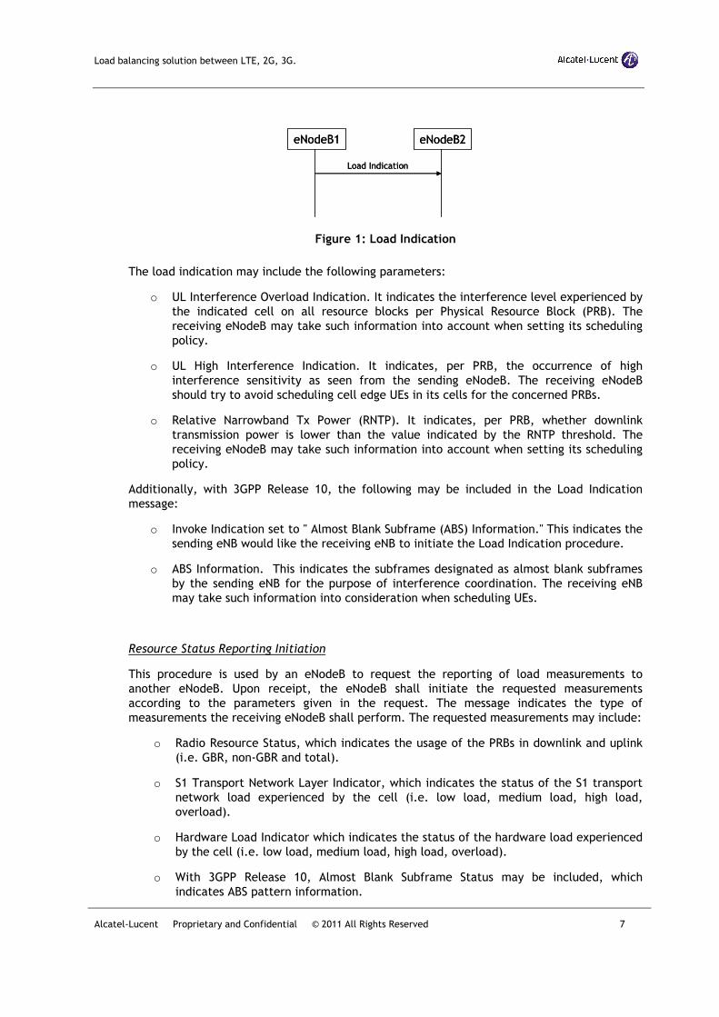
Figure 1: Load Indication
The load indication may include the following parameters:
o UL Interference Overload Indication. It indicates the interference level experienced by
the indicated cell on all resource blocks per Physical Resource Block (PRB). The
receiving eNodeB may take such information into account when setting its scheduling
policy.
o UL High Interference Indication. It indicates, per PRB, the occurrence of high
interference sensitivity as seen from the sending eNodeB. The receiving eNodeB
should try to avoid scheduling cell edge UEs in its cells for the concerned PRBs.
o Relative Narrowband Tx Power (RNTP). It indicates, per PRB, whether downlink
transmission power is lower than the value indicated by the RNTP threshold. The
receiving eNodeB may take such information into account when setting its scheduling
policy.
Additionally, with 3GPP Release 10, the following may be included in the Load Indication
message:
o Invoke Indication set to " Almost Blank Subframe (ABS) Information." This indicates the
sending eNB would like the receiving eNB to initiate the Load Indication procedure.
o ABS Information. This indicates the subframes designated as almost blank subframes
by the sending eNB for the purpose of interference coordination. The receiving eNB
may take such information into consideration when scheduling UEs.
Resource Status Reporting Initiation
This procedure is used by an eNodeB to request the reporting of load measurements to
another eNodeB. Upon receipt, the eNodeB shall initiate the requested measurements
according to the parameters given in the request. The message indicates the type of
measurements the receiving eNodeB shall perform. The requested measurements may include:
o Radio Resource Status, which indicates the usage of the PRBs in downlink and uplink
(i.e. GBR, non-GBR and total).
o S1 Transport Network Layer Indicator, which indicates the status of the S1 transport
network load experienced by the cell (i.e. low load, medium load, high load,
overload).
o Hardware Load Indicator which indicates the status of the hardware load experienced
by the cell (i.e. low load, medium load, high load, overload).
o With 3GPP Release 10, Almost Blank Subframe Status may be included, which
indicates ABS pattern information.
eNodeB1 eNodeB2
Load Indication
eNodeB1 eNodeB2
Load Indication
Load balancing solution between LTE, 2G, 3G.
Alcatel-Lucent Proprietary and Confidential © 2011 All Rights Reserved 8
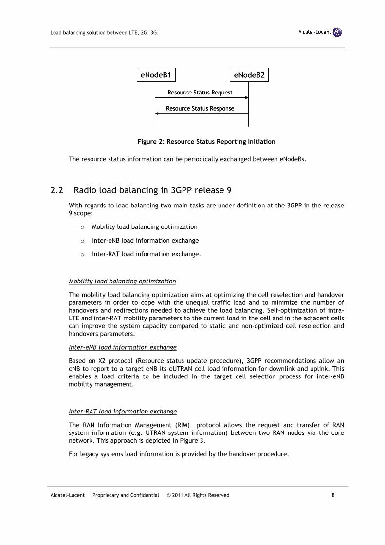
Figure 2: Resource Status Reporting Initiation
The resource status information can be periodically exchanged between eNodeBs.
2.2 Radio load balancing in 3GPP release 9
With regards to load balancing two main tasks are under definition at the 3GPP in the release
9 scope:
o Mobility load balancing optimization
o Inter-eNB load information exchange
o Inter-RAT load information exchange.
Mobility load balancing optimization
The mobility load balancing optimization aims at optimizing the cell reselection and handover
parameters in order to cope with the unequal traffic load and to minimize the number of
handovers and redirections needed to achieve the load balancing. Self-optimization of intra-
LTE and inter-RAT mobility parameters to the current load in the cell and in the adjacent cells
can improve the system capacity compared to static and non-optimized cell reselection and
handovers parameters.
Inter-eNB load information exchange
Based on X2 protocol (Resource status update procedure), 3GPP recommendations allow an
eNB to report to a target eNB its eUTRAN cell load information for downlink and uplink. This
enables a load criteria to be included in the target cell selection process for inter-eNB
mobility management.
Inter-RAT load information exchange
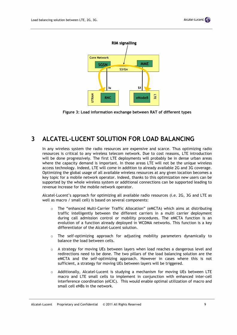
The RAN Information Management (RIM) protocol allows the request and transfer of RAN
system information (e.g. UTRAN system information) between two RAN nodes via the core
network. This approach is depicted in Figure 3.
For legacy systems load information is provided by the handover procedure.
eNodeB1 eNodeB2
Resource Status Request
Resource Status Response
eNodeB1 eNodeB2
Resource Status Request
Resource Status Response
Load balancing solution between LTE, 2G, 3G.
Alcatel-Lucent Proprietary and Confidential © 2011 All Rights Reserved 9
Figure 3: Load information exchange between RAT of different types
3 ALCATEL-LUCENT SOLUTION FOR LOAD BALANCING
In any wireless system the radio resources are expensive and scarce. Thus optimizing radio
resources is critical to any wireless telecom network. Due to cost reasons, LTE introduction
will be done progressively. The first LTE deployments will probably be in dense urban areas
where the capacity demand is important. In those areas LTE will not be the unique wireless
access technology. Indeed, LTE will come in addition to already available 2G and 3G coverage.
Optimizing the global usage of all available wireless resources at any given location becomes a
key topic for a mobile network operator. Indeed, thanks to this optimization new users can be
supported by the whole wireless system or additional connections can be supported leading to
revenue increase for the mobile network operator.
Alcatel-Lucent’s approach for optimizing all available radio resources (i.e. 2G, 3G and LTE as
well as macro / small cell) is based on several components:
o The “enhanced Multi-Carrier Traffic Allocation” (eMCTA) which aims at distributing
traffic intelligently between the different carriers in a multi carrier deployment
during call admission control or mobility procedures. The eMCTA function is an
evolution of a function already deployed in WCDMA networks. This function is a key
differentiator of the Alcatel-Lucent solution.
o The self-optimizing approach for adjusting mobility parameters dynamically to
balance the load between cells.
o A strategy for moving UEs between layers when load reaches a dangerous level and
redirections need to be done. The two pillars of the load balancing solution are the
eMCTA and the self-optimizing approach. However in cases where this is not
sufficient, a strategy for moving UEs between layers will be triggered.
o Additionally, Alcatel-Lucent is studying a mechanism for moving UEs between LTE
macro and LTE small cells to implement in conjunction with enhanced inter-cell
interference coordination (eICIC). This would enable optimal utilization of macro and
small cell eNBs in the network.
Iu
Core Network
S1
UTRAN L
TERNC eNodeB
MMESGSNS3/Gn
RIM signalling
Iu
Core Network
S1
UTRAN L
TERNCRNC eNodeBeNodeB
MMESGSNS3/Gn
RIM signalling
Load balancing solution between LTE, 2G, 3G.
Alcatel-Lucent Proprietary and Confidential © 2011 All Rights Reserved 10
This section starts with a description of the eMCTA function. Then the self-optimizing
approach for adjusting mobility parameters is described. To conclude the strategy for moving
UEs between layers is explained.
3.1 The eMCTA function
The eMCTA function aims at allocating traffic intelligently across multiple carriers during call
admission and mobility procedures. It applies to mobility management for both intra-LTE and inter-
RAT cases: Intra-LTE inter-frequency; LTE to GERAN; LTE to WCDMA; LTE to CDMA (TBC).
Two types of criteria can be used by the eMCTA function to take its decision:
o Criteria used for the definition of the operator strategy for service allocation on
available carriers
o Criteria related to the UE context as defined in 3GPP TS 36.413.
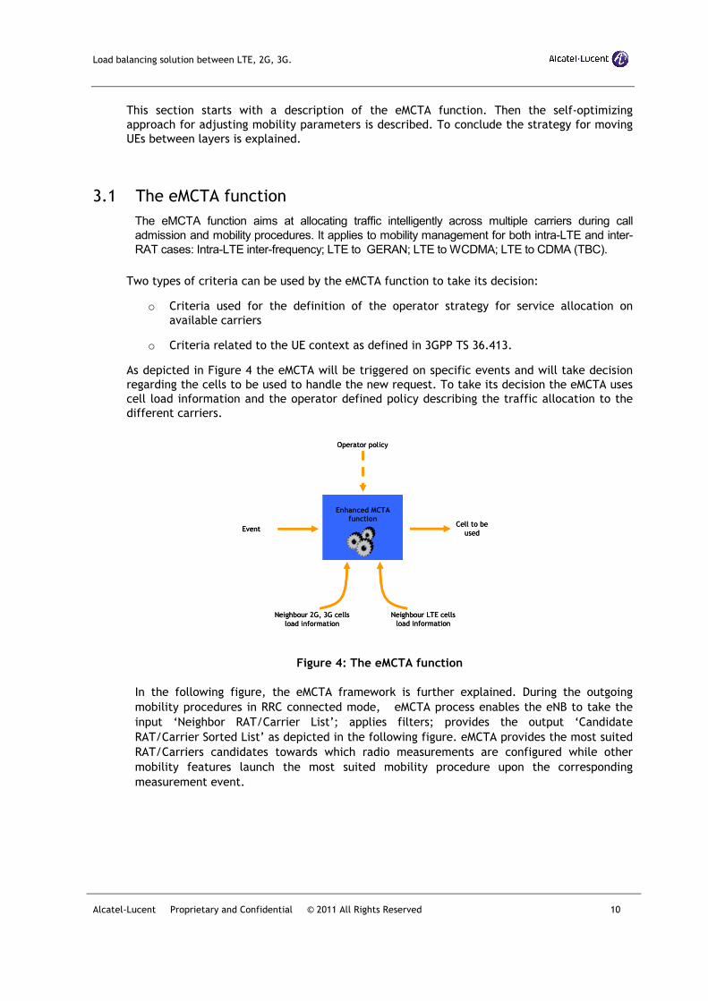
As depicted in Figure 4 the eMCTA will be triggered on specific events and will take decision
regarding the cells to be used to handle the new request. To take its decision the eMCTA uses
cell load information and the operator defined policy describing the traffic allocation to the
different carriers.
Figure 4: The eMCTA function
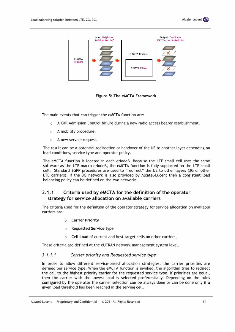
In the following figure, the eMCTA framework is further explained. During the outgoing
mobility procedures in RRC connected mode, eMCTA process enables the eNB to take the
input ‘Neighbor RAT/Carrier List’; applies filters; provides the output ‘Candidate
RAT/Carrier Sorted List’ as depicted in the following figure. eMCTA provides the most suited
RAT/Carriers candidates towards which radio measurements are configured while other
mobility features launch the most suited mobility procedure upon the corresponding
measurement event.
Enhanced MCTA
function
Neighbour LTE cells
load information
Neighbour 2G, 3G cells
load information
EventCell to be
used
Operator policy
Enhanced MCTA
function
Neighbour LTE cells
load information
Neighbour 2G, 3G cells
load information
EventCell to be
used
Operator policy
Load balancing solution between LTE, 2G, 3G.
Alcatel-Lucent Proprietary and Confidential © 2011 All Rights Reserved 11
Figure 5: The eMCTA Framework
The main events that can trigger the eMCTA function are:
o A Call Admission Control failure during a new radio access bearer establishment.
o A mobility procedure.
o A new service request.
The result can be a potential redirection or handover of the UE to another layer depending on
load conditions, service type and operator policy.
The eMCTA function is located in each eNodeB. Because the LTE small cell uses the same
software as the LTE macro eNodeB, the eMCTA function is fully supported on the LTE small
cell. Standard 3GPP procedures are used to “redirect” the UE to other layers (3G or other
LTE carriers). If the 3G network is also provided by Alcatel-Lucent then a consistent load
balancing policy can be defined on the two networks.
3.1.1 Criteria used by eMCTA for the definition of the operator
strategy for service allocation on available carriers
The criteria used for the definition of the operator strategy for service allocation on available
carriers are:
o Carrier Priority
o Requested Service type
o Cell Load of current and best target cells on other carriers,
These criteria are defined at the eUTRAN network management system level.
3.1.1.1 Carrier priority and Requested service type
In order to allow different service-based allocation strategies, the carrier priorities are
defined per service type. When the eMCTA function is invoked, the algorithm tries to redirect
the call to the highest priority carrier for the requested service type. If priorities are equal,
then the carrier with the lowest load is selected preferentially. Depending on the rules
configured by the operator the carrier selection can be always done or can be done only if a
given load threshold has been reached in the serving cell.
Load balancing solution between LTE, 2G, 3G.
Alcatel-Lucent Proprietary and Confidential © 2011 All Rights Reserved 12
The following table presents an example of a possible configuration in which:
o When available, LTE is preferred whatever the service
o UTRAN is preferred as a second choice
o GERAN is used as a third choice only.
LTE UTRAN GERAN
VoIP 0 (highest) 1 N/A
Video 0 (highest) 1 2 (lowest)
Best Effort 0 (highest) 1 2 (lowest)
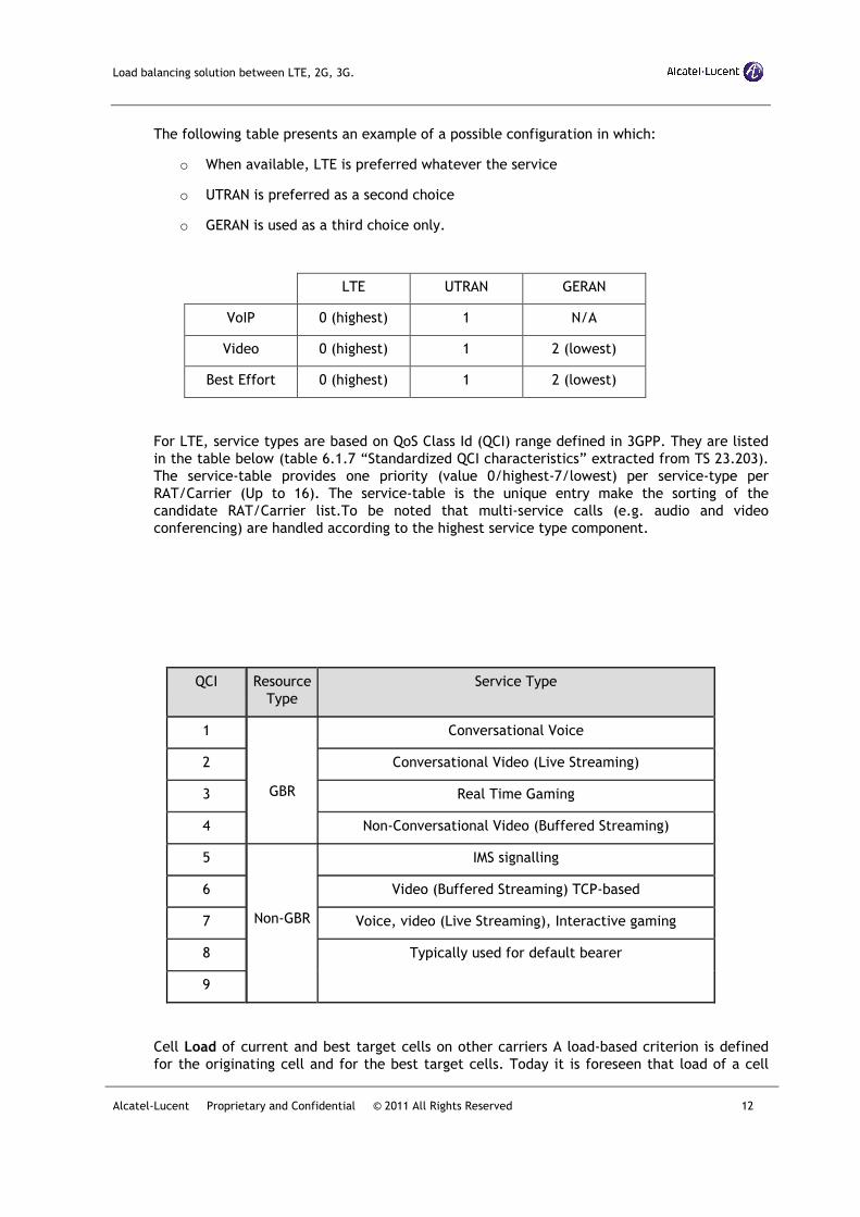
For LTE, service types are based on QoS Class Id (QCI) range defined in 3GPP. They are listed
in the table below (table 6.1.7 “Standardized QCI characteristics” extracted from TS 23.203).
The service-table provides one priority (value 0/highest-7/lowest) per service-type per
RAT/Carrier (Up to 16). The service-table is the unique entry make the sorting of the
candidate RAT/Carrier list.To be noted that multi-service calls (e.g. audio and video
conferencing) are handled according to the highest service type component.
QCI Resource
Type
Service Type
1
GBR
Conversational Voice
2 Conversational Video (Live Streaming)
3 Real Time Gaming
4 Non-Conversational Video (Buffered Streaming)
5
Non-GBR
IMS signalling
6 Video (Buffered Streaming) TCP-based
7 Voice, video (Live Streaming), Interactive gaming
8 Typically used for default bearer
9
Cell Load of current and best target cells on other carriers A load-based criterion is defined
for the originating cell and for the best target cells. Today it is foreseen that load of a cell
Load balancing solution between LTE, 2G, 3G.
Alcatel-Lucent Proprietary and Confidential © 2011 All Rights Reserved 13
will be defined by the concept of “cell colour” (as already the case in 3G). Three colours will
probably be defined to reflect the cell load; green, yellow and red.
When the serving cell radio resource is congested or in a heavily loaded condition, eMCTA will
trigger mobility behavior to neighbor cells.
The target cell load criterion is a new eMCTA filter. It applies when eMCTA is triggered upon
bad radio conditions, Alarm, preventive load control and reactive load control. A target cell
may have several load information (several IE on X2 and S1). The target load criteria applying
to neighboring cell located on the serving eNB will be based on load information with X2
format.
Based on 3GPP Rel9 definition:
RIM doesn’t allow exchanging load information between two eNB which may not have
an X2 interface.
Load information exchanged over X2 may only be done in a periodic mode. Multi cell
reporting may apply. Max period value is 10 sec.
Load information exchange over S1 may only be done in mono reporting mode. Mono
cell reporting applies.
3GPP doesn’t define event mode on S1 and X2 in order to refresh load information state.
In the originating cell, the load level is used to define the level of load above which the
eMCTA function is triggered. The originating cell eMCTA can be always triggered (i.e. cell is
green) or can be triggered only if the cell becomes loaded (i.e. cell is yellow) or congested
(i.e. cell is red).
In the target cell, the load level is used to avoid redirection to an overloaded cell.
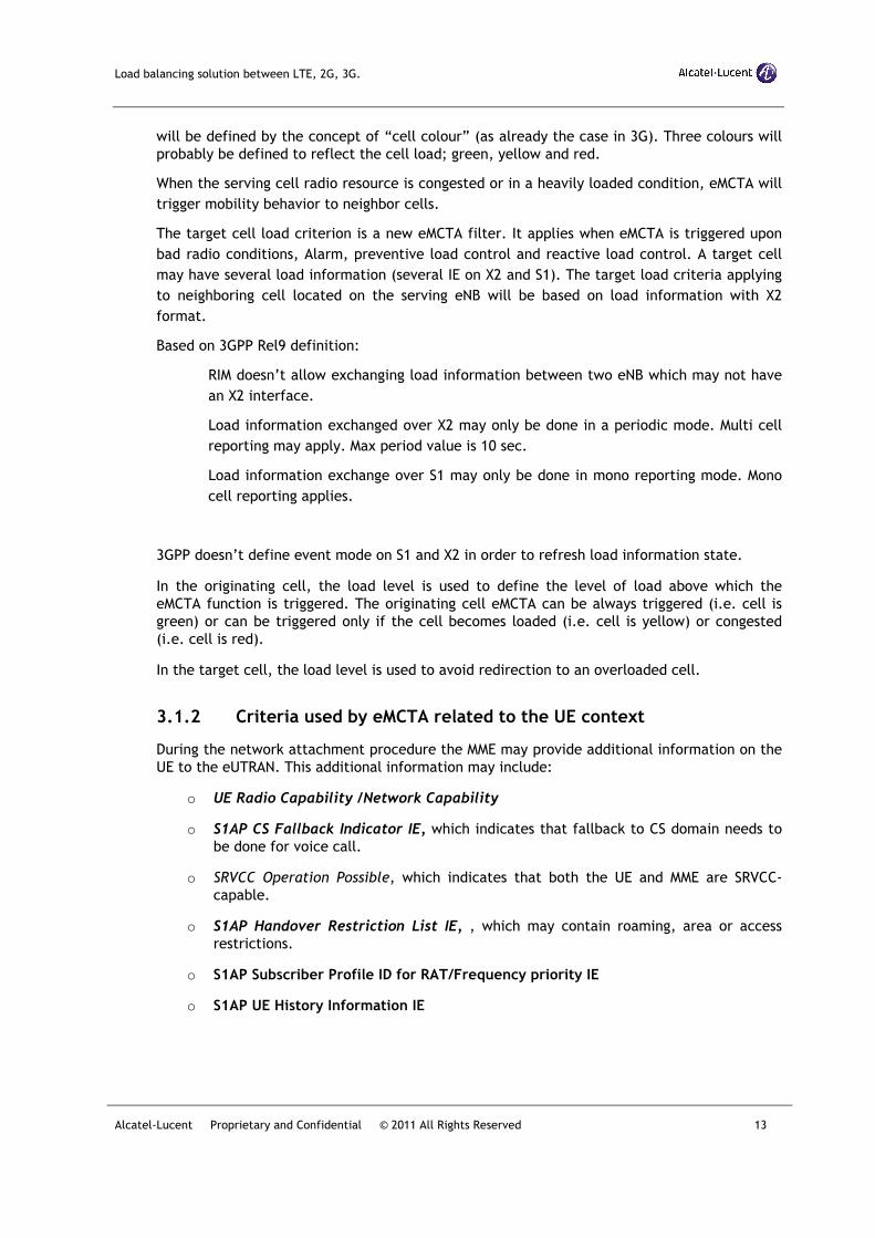
3.1.2 Criteria used by eMCTA related to the UE context
During the network attachment procedure the MME may provide additional information on the
UE to the eUTRAN. This additional information may include:
o UE Radio Capability /Network Capability
o S1AP CS Fallback Indicator IE, which indicates that fallback to CS domain needs to
be done for voice call.
o SRVCC Operation Possible, which indicates that both the UE and MME are SRVCC-
capable.
o S1AP Handover Restriction List IE, , which may contain roaming, area or access
restrictions.
o S1AP Subscriber Profile ID for RAT/Frequency priority IE
o S1AP UE History Information IE
Load balancing solution between LTE, 2G, 3G.
Alcatel-Lucent Proprietary and Confidential © 2011 All Rights Reserved 14
The MME may also include the UE History Information IE in each handover request, which
contains information about cells that a UE has been served by in active state prior to the
target cell and in particular the duration of the time the UE stayed in the cell in seconds.
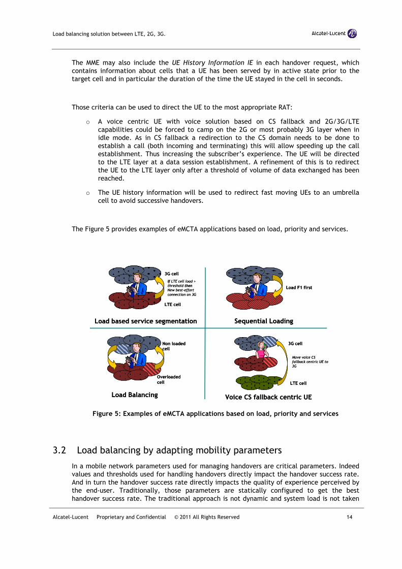
Those criteria can be used to direct the UE to the most appropriate RAT:
o A voice centric UE with voice solution based on CS fallback and 2G/3G/LTE
capabilities could be forced to camp on the 2G or most probably 3G layer when in
idle mode. As in CS fallback a redirection to the CS domain needs to be done to
establish a call (both incoming and terminating) this will allow speeding up the call
establishment. Thus increasing the subscriber’s experience. The UE will be directed
to the LTE layer at a data session establishment. A refinement of this is to redirect
the UE to the LTE layer only after a threshold of volume of data exchanged has been
reached.
o The UE history information will be used to redirect fast moving UEs to an umbrella
cell to avoid successive handovers.
The Figure 5 provides examples of eMCTA applications based on load, priority and services.
Figure 5: Examples of eMCTA applications based on load, priority and services
3.2 Load balancing by adapting mobility parameters
In a mobile network parameters used for managing handovers are critical parameters. Indeed
values and thresholds used for handling handovers directly impact the handover success rate.
And in turn the handover success rate directly impacts the quality of experience perceived by
the end-user. Traditionally, those parameters are statically configured to get the best
handover success rate. The traditional approach is not dynamic and system load is not taken
Load based service segmentation
LTE cell
3G cell
Copyrig
ht ©
1996 N
orth
ern
Tele
com
Sequential Loading
Load F1 first
Copyrig
ht ©
1996 N
orth
ern
Tele
com
Load Balancing
Overloaded
cell
Copyrig
ht ©
1996 N
orth
ern
Tele
com
Non loaded cell
3G cell
LTE cell
Copyright ©
1996 N
orther
n T
elec
om
Voice CS fallback centric UE
If LTE cell load > threshold thenNew best-effort
connection on 3G
Move voice CS
fallback centric UE to
3G
Load balancing solution between LTE, 2G, 3G.
Alcatel-Lucent Proprietary and Confidential © 2011 All Rights Reserved 15
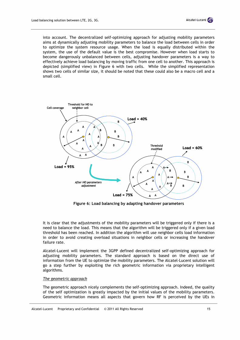
into account. The decentralized self-optimizing approach for adjusting mobility parameters
aims at dynamically adjusting mobility parameters to balance the load between cells in order
to optimize the system resource usage. When the load is equally distributed within the
system, the use of the default value is the best compromise. However when load starts to
become dangerously unbalanced between cells, adjusting handover parameters is a way to
effectively achieve load balancing by moving traffic from one cell to another. This approach is
depicted (simplified view) in Figure 6 with two cells. While the simplified representation
shows two cells of similar size, it should be noted that these could also be a macro cell and a
small cell.
Figure 6: Load balancing by adapting handover parameters
It is clear that the adjustments of the mobility parameters will be triggered only if there is a
need to balance the load. This means that the algorithm will be triggered only if a given load
threshold has been reached. In addition the algorithm will use neighbor cells load information
in order to avoid creating overload situations in neighbor cells or increasing the handover
failure rate.
Alcatel-Lucent will implement the 3GPP defined decentralized self-optimizing approach for
adjusting mobility parameters. The standard approach is based on the direct use of
information from the UE to optimize the mobility parameters. The Alcatel-Lucent solution will
go a step further by exploiting the rich geometric information via proprietary intelligent
algorithms.
The geometric approach
The geometric approach nicely complements the self-optimizing approach. Indeed, the quality
of the self optimization is greatly impacted by the initial values of the mobility parameters.
Geometric information means all aspects that govern how RF is perceived by the UEs in
Cell coverage
Threshold for HO to
neighbor cell
AA
A
A
A
A
A
AA
A
A
B
B
B
B
B
B
Load = 95%
Load = 40%
A
A
A
AA
A
A
A
A
A
AA
A
A
B
B
B
B
B
B
Load = 75%
Load = 60%
A
A
A
After HO parameters
adjustment
Threshold
modified
Cell coverage
Threshold for HO to
neighbor cell
AA
A
A
A
A
A
AA
A
A
B
B
B
B
B
B
Load = 95%
Load = 40%
A
A
A
AA
A
A
A
A
A
AA
A
A
B
B
B
B
B
B
Load = 75%
Load = 60%
A
A
A
After HO parameters
adjustment
Threshold
modified
Load balancing solution between LTE, 2G, 3G.
Alcatel-Lucent Proprietary and Confidential © 2011 All Rights Reserved 16
different geometrical locations. Therefore, the term geometry involves location information
of eNodeBs, antenna height and azimuth and frequency band. Alcatel-Lucent has developed an
extensive set of algorithms that addresses local geometrical challenges while exploiting local
opportunities to prescribe good initial parameter values based on geometry information. This
means that the decentralized self-optimizing approach for adjusting mobility parameters will
start off with an already good initial set of values to provide improved performance. Alcatel-
Lucent sees these geometric algorithms as a strong differentiator for any type of deployment.
Inter RAT context
It should be noted that the approach described above aiming at adapting dynamically the
mobility parameters could be extended to an inter RAT context. The approach will aim at
dynamically updating in a consistent manner the 3G and LTE mobility parameters to move UEs
between the 3G and the LTE layer when needed. However, supporting such an approach is
subject to standardization.
3.3 Traffic load balancing between RATs
As mentioned in the previous sections the Alcatel-Lucent load balancing solution is composed
of several components aiming at balancing the traffic between carriers. In most cases the use
of both the eMCTA function and the dynamic adjustments of mobility parameters will be
enough to balance the load between available carriers.
However in cases where this is not sufficient, a strategy for moving UEs between layers will be
triggered to solve dangerous unbalanced situations.
The general strategy is:
1. To support both intra-LTE and inter-RAT load balancing.
2. When an inter-RAT load balancing is needed to select first the UEs with best-
effort connections before UEs with QoS sensitive connections.
Intra-LTE load balancing
This will be achieved by triggering the self-optimizing approach for adjusting mobility
parameters described in section 3.2.
For intra-frequency LTE cells the inter-cell interference coordination (ICIC) function is a
powerful technique to improve the performances at cell edge. Indeed, in case of intra-
frequency LTE cells as the radio signal conditions are rather difficult at the border region
between two cells (i.e. reuse-1 and no scrambling gain) it is anticipated that the margin for
the variation of the handover threshold between two cells without impacting the handover
failure rate will be rather small. In this context ICIC is a technique that can improve the intra-
frequency intra-LTE load balancing by a more efficient usage of the radio resources between
involved cells. The load itself is not moved away from heavily loaded cells but resources are
conceptually moved into the heavily loaded cells by managing interference on physical
resource blocks.
Load balancing solution between LTE, 2G, 3G.
Alcatel-Lucent Proprietary and Confidential © 2011 All Rights Reserved 17
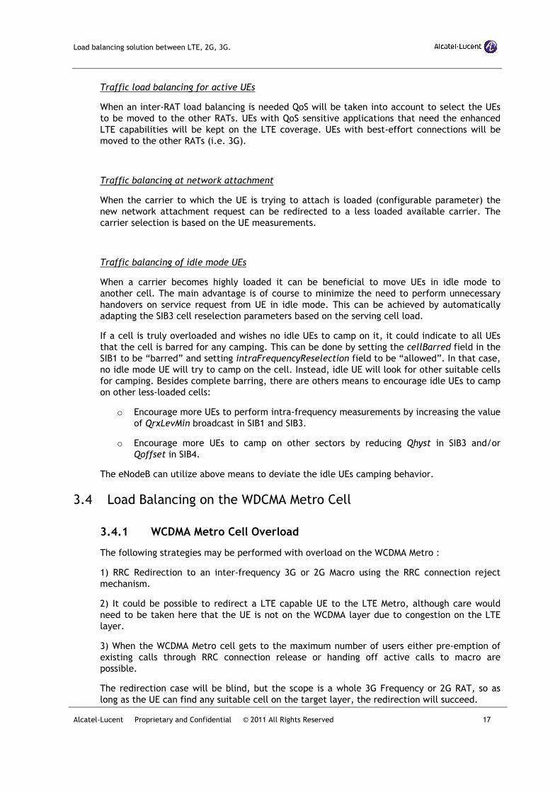
Traffic load balancing for active UEs
When an inter-RAT load balancing is needed QoS will be taken into account to select the UEs
to be moved to the other RATs. UEs with QoS sensitive applications that need the enhanced
LTE capabilities will be kept on the LTE coverage. UEs with best-effort connections will be
moved to the other RATs (i.e. 3G).
Traffic balancing at network attachment
When the carrier to which the UE is trying to attach is loaded (configurable parameter) the
new network attachment request can be redirected to a less loaded available carrier. The
carrier selection is based on the UE measurements.
Traffic balancing of idle mode UEs
When a carrier becomes highly loaded it can be beneficial to move UEs in idle mode to
another cell. The main advantage is of course to minimize the need to perform unnecessary
handovers on service request from UE in idle mode. This can be achieved by automatically
adapting the SIB3 cell reselection parameters based on the serving cell load.
If a cell is truly overloaded and wishes no idle UEs to camp on it, it could indicate to all UEs
that the cell is barred for any camping. This can be done by setting the cellBarred field in the
SIB1 to be “barred” and setting intraFrequencyReselection field to be “allowed”. In that case,
no idle mode UE will try to camp on the cell. Instead, idle UE will look for other suitable cells
for camping. Besides complete barring, there are others means to encourage idle UEs to camp
on other less-loaded cells:
o Encourage more UEs to perform intra-frequency measurements by increasing the value
of QrxLevMin broadcast in SIB1 and SIB3.
o Encourage more UEs to camp on other sectors by reducing Qhyst in SIB3 and/or
Qoffset in SIB4.
The eNodeB can utilize above means to deviate the idle UEs camping behavior.
3.4 Load Balancing on the WDCMA Metro Cell
3.4.1 WCDMA Metro Cell Overload
The following strategies may be performed with overload on the WCDMA Metro :
1) RRC Redirection to an inter-frequency 3G or 2G Macro using the RRC connection reject
mechanism.
2) It could be possible to redirect a LTE capable UE to the LTE Metro, although care would
need to be taken here that the UE is not on the WCDMA layer due to congestion on the LTE
layer.
3) When the WCDMA Metro cell gets to the maximum number of users either pre-emption of
existing calls through RRC connection release or handing off active calls to macro are
possible.
The redirection case will be blind, but the scope is a whole 3G Frequency or 2G RAT, so as
long as the UE can find any suitable cell on the target layer, the redirection will succeed.
Load balancing solution between LTE, 2G, 3G.
Alcatel-Lucent Proprietary and Confidential © 2011 All Rights Reserved 18
The handover case can make use of mobile assisted measurements to guide the handover.
4) Service based handover - it is possible to dedicate the Metro Cell to data only to take the
highest resource consuming users (PS Data) onto the Metro cell, and leave lower resource
consuming services such a voice on the Macro.
In an isolated Metro cell it can be possible to shrink coverage as the cell starts to get to full
load to avoid attracting too many UEs.
In a mesh scenario, any coverage reduction to avoid overload should take into account the
necessary coverage overlap between small cells to avoid making coverage holes. Whitepaper
B3_5 provides further details on this.
3.4.2 Reselection from WCMA to LTE and SIB 19 Support
Generally a UE will be expected to camp and reselect directly on the LTE Metro layer.
However, in the case that the UE is on the WCDMA metro cell e.g. redirected to the WCDMA
metro from the LTE Metro, or in the case where the footprints are different, SIB 19 broadcast
allows the UE to reselect to the LTE Metro layer.
In the case that the LTE Metro layer is overloaded, it is possible to prevent reselection to that
cell from the WCDMA Metro Cell by indicating that it is blacklisted in the system information
broadcast.
3.4.3 Load Measurements of the WCDMA Macro
The loading of the WCDMA macro cell could be used to determine the optimal layer to
handover to or redirect to from the Metro Cell. It is not simple to get the information
transferred between the two technologies due to the following considerations :
1) The RAN Information Management (RIM) could be used to pass load information using the
SON Transfer RIM application through the Core Network. However, 48.018, section 8c.6.4
limits this procedure to inter-RAT exchange. This means that intra-system load information
sharing through the CN is against the current versions of 3GPP standards.
In addition, any information transfer through the CN would involve CN loading, and rapid
updates for many cells could be intensive for both the RNC and the CN.
2) The 3GPP standard allows cell load information to be passed through an Iur link. The Iur
link would require a new interface from the Metro Gateway to the RNC.
If such an interface were developed, the RNC would need to expect many more common
measurements than normally supported. The Metro Gateway would need to act as a
concentrator for the measurements and request one set of measurements to pass to the
relevant Metro Cells which see the Macro cells as neighbours.
3.4.4 Load Measurements of the WCDMA Metro
The mechanisms for the WCDMA Macro to determine WCDMA Metro load are the same as for
the WCDMA Metro to determine WCDMA Macro load, but with the additional considerations :
If there is PSC reuse on the Metro Cell, the Macro will not know which cell is applicable to a
UE being handed over from the Macro to the Metro, and makes the load information
ambiguous (See Incoming HO Whitepaper).
Load balancing solution between LTE, 2G, 3G.
Alcatel-Lucent Proprietary and Confidential © 2011 All Rights Reserved 19
It is therefore doubtful whether the WCDMA macro could make good use of such load
measurements.
4 ALCATEL-LUCENT WLAN OFFLOAD SOLUTION
The Alcatel-Lucent solution for load balancing with WiFi is provided using the Access Network
Discovery and Selection Function (ANDSF). This provides a 3GPP standardized mechanism to
aid the UE in access network discover and selection. Operator provided information, includes:
� Inter-system mobility policy (pre-IFOM UEs) - provides guidance according to access
technology, network ID, etc.
� Access network discovery information – provides list of access networks in the
vicinity of the UE, including access technologies, frequencies, & validity conditions
(eg: location)
� Inter-System Routing Policy – per-flow or per-APN polices for routing packet flows
for UEs that are capable of routing IP traffic simultaneously over multiple radio
access interfaces. It is also used to support Non-seamless WLAN offload.
ANDSF function is defined in 3GPP 23.402. ANDSF supplies the UE with information for
discovering and selecting appropriate access networks according to service provider policies.
It implements a new standardized interface (S14) between a network server and the UE.
Different phases are currently planned:
� Phase 1 provides the basic functionality on the server and UE ANDSF functionality.
It includes support for the S14 interface, security mechanisms as required by 3GPP
33.402, and server provisioned inter-system mobility and network discovery policies.
UE Access is via 3GPP.
� Phase 2 adds inter-working with the Network Assisted WLAN off-load feature to
provide real-time intelligence to assist with network selection decisions.
� Phase 3 adds support for per-APN and per-flow policies to support MAPCON and
IFOM. This includes S14 support for Untrusted Non-3GPP Access via secure tunnels
to the EPC. Interworking with Intelligent Presence is provided for service provider
policy driven guidance of network connections on a per-application basis.
ALU Network Assisted WLAN off-load provides network intelligence to ANDSF so better
decisions may be made in selecting the network priorities communicated to the UE. For 3GPP
R8, Network Assisted WLAN off-load formulates the inter-system mobility policy by
incorporating information from several sources, including the UE, network probes, the
HSS/SPR, provisioned operator policy and subscriber preferences. Factors that may be
considered in assessing network priorities include, expected performance on WLAN APs, UE
mobility, subscriber subscription level, access to operator services and current subscriber data
usage. This allows tailoring of the mobility policy to maximize the QoE for individual
subscribers while taking into account the impact those subscriber have on the mobility
network.
For 3GPP R8, Network Assisted WLAN off-load provides a prioritized list that can be
communicated using the standard ANDSF S14 interface. In addition ALU provides enhanced
functions available with an extended S14 interface supported with partner ANDSF clients. The
enhancements provide:
Load balancing solution between LTE, 2G, 3G.
Alcatel-Lucent Proprietary and Confidential © 2011 All Rights Reserved 20
1. Communication of Wifi Access Point performance information to an ALU Reputation
Database. The information in the database is used to determine whether UEs will
receive better service on WiFi or the mobility network.
2. Dynamic queries that allow for relative QoE assessment between Wifi and the mobility
network, taking into account mobility network congestion and expected Wifi access
point performance. Prior to attaching to an access point based on Inter-system
mobility policy received via the standard S14 interface, the UE sends an additional
query containing the results of WLAN scan. This information, combined with
information received from the Reputation Database, and mobility network congestion
information, is used to select the best access option, which is then communicated to
the UE.
5 ALCATEL-LUCENT KEY DIFFERENTIATORS
The Alcatel-Lucent load balancing solution key differentiators are:
1. The eMCTA feature. This feature aims at intelligently distributing the load between
the different layers in a multi layers deployment. This feature is an evolution of a
feature already available in 3G. The eMCTA function provides the operator with a
flexible approach for defining its strategy in terms of carrier priority and service
allocation on available carriers. The benefits are a higher success rate in case of
alarm or call admission control failure and a better load balancing between LTE, 3G
and 2G carriers. This feature can also be utilized in a Heterogeneous Network
(HetNET) when operator starts to include small cells into the wireless network.
2. Alcatel-Lucent will go further than what will be defined in the 3GPP standard release
10 for self-optimization of mobility parameters by exploiting the rich geometric
information via proprietary intelligent algorithms. This approach will allow prescribing
good initial parameter values based on geometry information. The decentralized self-
optimizing approach for adjusting mobility parameters will start off with an already
good initial set of values to provide improved performances.
3. 3GPPdefine ANDSF provides a standardized mechanism to communicate network
policies and node discovery information associated with WLAN access. Alcatel-
Lucent’s offering enhances the standardized Network<->UE communication channel
provided by ANDSF with Network Assisted WLAN off-load. Network Assisted WLAN
off-load adds network intelligence to the network selection decision process, changing
the dynamic for network selection from one that involves a binary interaction
between a subscriber and their device, to a three way decision process that exploits
network intelligence. The goal of the process is always pick the best connection for
the device, taking into account service provider policies, network congestion, Wifi AP
performance, UE mobility, data usage patterns, subscribed services and other factors
known to the network.
Load balancing solution between LTE, 2G, 3G.
Alcatel-Lucent Proprietary and Confidential © 2011 All Rights Reserved 21
6 CONCLUSION
LTE will be deployed in areas already covered by 2G and 3G networks. The result will be a
multilayer network composed of both 2G, 3G and LTE layers, and even small cells, as well as
WiFi. Balancing the load between all available layers will be an important feature to optimize
the system capacity. Alcatel-Lucent load balancing solution is composed of several
components described in this document. Those components aim at intelligently distributing
the load between available carriers and offering the operator the tools to fully define its load
sharing strategy to better address its needs.
Load balancing solution between LTE, 2G, 3G.
Alcatel-Lucent Proprietary and Confidential © 2011 All Rights Reserved 22
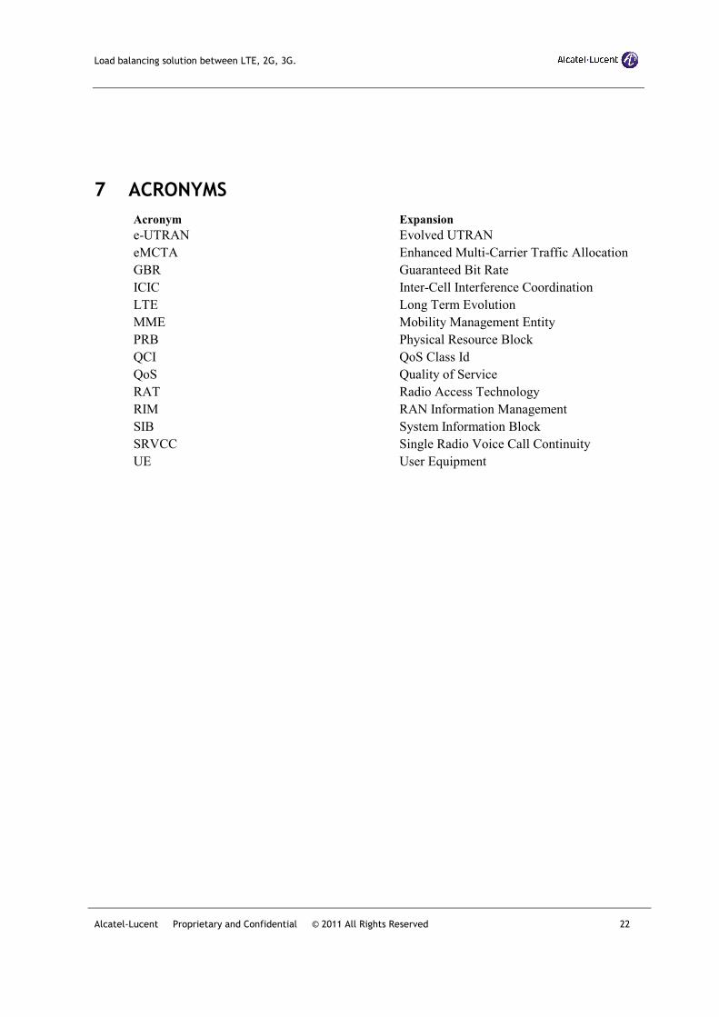
7 ACRONYMS
Acronym Expansion
e-UTRAN Evolved UTRAN
eMCTA Enhanced Multi-Carrier Traffic Allocation
GBR Guaranteed Bit Rate
ICIC Inter-Cell Interference Coordination
LTE Long Term Evolution
MME Mobility Management Entity
PRB Physical Resource Block
QCI QoS Class Id
QoS Quality of Service
RAT Radio Access Technology
RIM RAN Information Management
SIB System Information Block
SRVCC Single Radio Voice Call Continuity
UE User Equipment