alternating current electricity
DESCRIPTION
Alternating Current Electricity. NCEA A.S 3.6 Text Chapters 18-19. Why AC?. It can be produced directly from generators It can be controlled by a wide range of components eg resistors,capacitors and inductors. The max voltage can be changed easily using a transformer - PowerPoint PPT PresentationTRANSCRIPT

Alternating Current Alternating Current ElectricityElectricity
NCEA A.S 3.6NCEA A.S 3.6
Text Chapters 18-19Text Chapters 18-19

Why AC?Why AC?
It can be produced directly from It can be produced directly from generatorsgenerators
It can be controlled by a wide range of It can be controlled by a wide range of components eg resistors,capacitors and components eg resistors,capacitors and inductors.inductors.
The max voltage can be changed easily The max voltage can be changed easily using a transformerusing a transformer
The frequency of the AC can be used for The frequency of the AC can be used for timingtiming

AC CurrentAC Current

AC VoltageAC Voltage

AC AC PowerPowerP=VxIP=VxI
Multiplying Multiplying the graphs the graphs gives us a gives us a graph graph where the where the power is power is always always positivepositive

AC PowerAC Power
The average voltage in ac is zero since The average voltage in ac is zero since there is an equal amount of positive and there is an equal amount of positive and negative voltage.negative voltage.
Same for currentSame for current
The average value of the power used in ac The average value of the power used in ac is is halfhalf that of the peak power that of the peak power

RMS ValuesRMS Values
Since voltage and current are always Since voltage and current are always changing we need some way of averaging changing we need some way of averaging out their effect.out their effect.
We use r.m.s values (root-mean-square)We use r.m.s values (root-mean-square)
The r.m.s values are the DC values which The r.m.s values are the DC values which give the same average power outputgive the same average power output

RMS ValuesRMS ValuesAC Voltage DC Voltage
(with same power output)
Vrms
Vmax

RMS ValuesRMS Values
2maxV
Vrms
2maxI
I rms (See text pg 295-296 for derivations of these formulae)

AC in CapacitorsAC in Capacitors
In a DC circuit, the current flows until the cap is In a DC circuit, the current flows until the cap is fully charged and then stops.fully charged and then stops.In an AC circuit, the current can continue to flow, In an AC circuit, the current can continue to flow, as the plates become alternately charged as the plates become alternately charged positively and negatively positively and negatively
~~

ReactanceReactance
For both AC and DC circuits, the voltage For both AC and DC circuits, the voltage across the resistor is related to the current across the resistor is related to the current by V=IRby V=IRA similar relationship exists for a capacitor:A similar relationship exists for a capacitor:
Where XWhere Xcc is the is the reactancereactance of the capacitor of the capacitor
~~
cc IXV

ReactanceReactance
Reactance is a measure of how a Reactance is a measure of how a capacitor can limit alternating currentcapacitor can limit alternating current
Unit: OhmsUnit: Ohms
It is It is similarsimilar to resistance but differs in that to resistance but differs in that it is dependent on the it is dependent on the frequencyfrequency of the ac of the ac supply.supply.
It also depends on the size of the It also depends on the size of the capacitor.capacitor.

ReactanceReactance
Explanations:Explanations:
Higher f means cap never gets full before Higher f means cap never gets full before current direction changes, so never limits current direction changes, so never limits current, so low Xcurrent, so low X
Higher C means that it takes more charge to fill Higher C means that it takes more charge to fill it, so never fills before current direction changes, it, so never fills before current direction changes, so never limits current, so low Xso never limits current, so low X
fCX c 2
1

Phase RelationshipPhase RelationshipIn a DC circuit the voltage across In a DC circuit the voltage across components connected in series will add components connected in series will add up to the supply voltageup to the supply voltage
In AC circuits this does not happenIn AC circuits this does not happen
Eg. Eg.
~~
VS
VCVR
RCS
R
C
S
VVV
VV
VV
VV
8
6
12

Phase RelationshipPhase Relationship
Reasons:Reasons: The meters used to measure the voltage will The meters used to measure the voltage will
give rms values, not actual voltages at a give rms values, not actual voltages at a point in timepoint in time
The voltages across the resistor and capacitor The voltages across the resistor and capacitor are out of phase with each other ie they do are out of phase with each other ie they do not both reach maxs and mins at the same not both reach maxs and mins at the same time.time.

Phase RelationshipPhase RelationshipThe current in the circuit will always be in The current in the circuit will always be in phase with Vphase with VR R (Reason: because R is constant (Reason: because R is constant
so bigger V gives bigger I)so bigger V gives bigger I)
This can be shown on a phasor diagram:This can be shown on a phasor diagram:
VR
VR
It
Iω VR
Phase RelationshipPhase Relationship
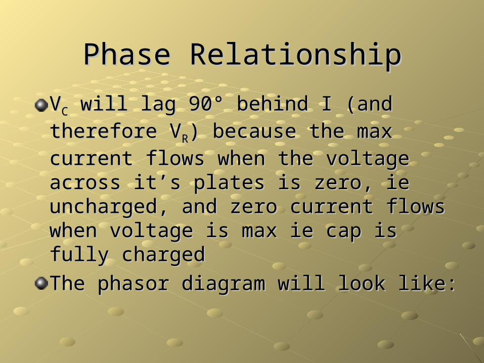
VVCC will lag 90 will lag 90° behind I (and therefore V° behind I (and therefore VRR) )
because the max current flows when the because the max current flows when the voltage across it’s plates is zero, ie voltage across it’s plates is zero, ie uncharged, and zero current flows when uncharged, and zero current flows when voltage is max ie cap is fully chargedvoltage is max ie cap is fully charged
The phasor diagram will look like:The phasor diagram will look like:

Phase RelationshipPhase Relationship
The voltage phasors are not necessarily the The voltage phasors are not necessarily the same size, but are always 90same size, but are always 90°out of phase°out of phase
VR
It
Iω
VC
VR
VC

RC CircuitsRC CircuitsThe total voltage in the circuit can be The total voltage in the circuit can be found by adding the Vfound by adding the VRR and V and VCC phasors phasors
together together
VR
tω
VCVR
VC
Vs
VS
222CRS VVV
ImpedanceImpedance
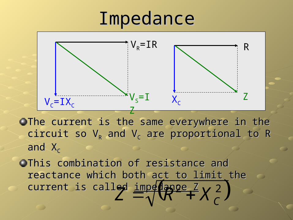
The current is the same everywhere in the circuit The current is the same everywhere in the circuit so Vso VRR and V and VCC are proportional to R and X are proportional to R and XCC
This combination of resistance and reactance This combination of resistance and reactance which both act to limit the current is called which both act to limit the current is called impedance Zimpedance Z
VR=IR
VC=IXCVS=IZ
R
XCZ
22CXRZ

AC in InductorsAC in InductorsIn a DC circuit an inductor produces an In a DC circuit an inductor produces an opposing voltage whenever the current opposing voltage whenever the current changes.changes.In an AC circuit, the current is always In an AC circuit, the current is always changing so the inductor is always changing so the inductor is always producing an opposing voltage so is producing an opposing voltage so is always limiting the amount of current that always limiting the amount of current that can flowcan flow ~~

ReactanceReactance
For both AC and DC circuits, the voltage For both AC and DC circuits, the voltage across the resistor is related to the current across the resistor is related to the current by V=IRby V=IRA similar relationship exists for an inductor:A similar relationship exists for an inductor:
Where XWhere XLL is the is the reactancereactance of the inductor of the inductor
LL IXV ~~

ReactanceReactance
It measures how well an inductor can limit It measures how well an inductor can limit alternating currentalternating current
It depends on the It depends on the frequencyfrequency of the ac of the ac supply.supply.
It depends on the size of the inductor.It depends on the size of the inductor.

ReactanceReactance
Explanations:Explanations:
Higher f means faster rate of change of current, Higher f means faster rate of change of current, so more back e.m.f, so less current, so higher Xso more back e.m.f, so less current, so higher XLL
Higher L means more back e.m.f, so less Higher L means more back e.m.f, so less current, so higher Xcurrent, so higher XLL
fLX L 2

Phase RelationshipPhase Relationship
VVLL will lead will lead I (and therefore VI (and therefore VRR) by ) by 9090° °
because the greatest back e.m.f occurs because the greatest back e.m.f occurs when the current is changing most rapidly, when the current is changing most rapidly, which is when it is passing through zero. which is when it is passing through zero. When the current has reached it’s max, it When the current has reached it’s max, it is not changing as rapidly so there is no is not changing as rapidly so there is no back e.m.f back e.m.f
The phasor diagram will look like:The phasor diagram will look like:

Phase RelationshipPhase Relationship
Again the voltages may be different sizes Again the voltages may be different sizes but will always be 90but will always be 90° out of phase° out of phase
VR
It
Iω
VL
VR
VL

LR CircuitsLR CircuitsThe total voltage in the circuit can be The total voltage in the circuit can be found by adding the Vfound by adding the VRR and V and VLL phasors phasors
together together
VR
tω
VLVR
VL VsVS
222LRS VVV

ImpedanceImpedance
The The impedance Z impedance Z is found by adding R and Xis found by adding R and XLL
VR=IR
VL=IXLVS=IZ
R
XLZ
22LXRZ

LCR CircuitsLCR Circuits
This can be an extremely useful circuit set-This can be an extremely useful circuit set-up, as the current and voltages can up, as the current and voltages can change considerably as the frequency is change considerably as the frequency is changedchanged
~~

LCR CircuitsLCR Circuits
The combined phasor diagram now looks like:The combined phasor diagram now looks like:
t
VR
ω
VL
VR
VLVs
VS
VC
VC
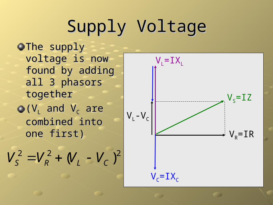
Supply VoltageSupply VoltageThe supply The supply voltage is now voltage is now found by adding found by adding all 3 phasors all 3 phasors togethertogether
(V(VLL and V and VCC are are
combined into one combined into one first)first)
VR=IR
VL=IXL
VS=IZ
VC=IXC
VL-VC
222 )( CLRS VVVV
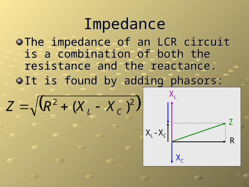
ImpedanceImpedanceThe impedance of an LCR circuit is a The impedance of an LCR circuit is a combination of both the resistance and the combination of both the resistance and the reactance.reactance.It is found by adding phasors:It is found by adding phasors:
R
XL
Z
XC
XL-XC
22 )( CL XXRZ

ResonanceResonance
At low f, VAt low f, VCC>V>VLL
so Vso VR R (and (and
therefore I) is therefore I) is small.small.
ie. Capacitors ie. Capacitors limit the current limit the current better at low better at low frequenciesfrequencies
VR
VL
VS
VC

ResonanceResonance
At high f, VAt high f, VLL>V>VCC
so Vso VR R (and (and
therefore I) is therefore I) is small.small.
ie. Inductors limit ie. Inductors limit the current the current better at high better at high frequenciesfrequencies
VR
VL
VS
VC

ResonanceResonance
At resonance, At resonance, VVLL=V=VCC and they and they
cancel each cancel each other out. So other out. So VVSS=V=VR R and if V and if VRR
is at max then I is at max then I is at max.is at max.
VR
VL
VS
VC
ResonanceResonance
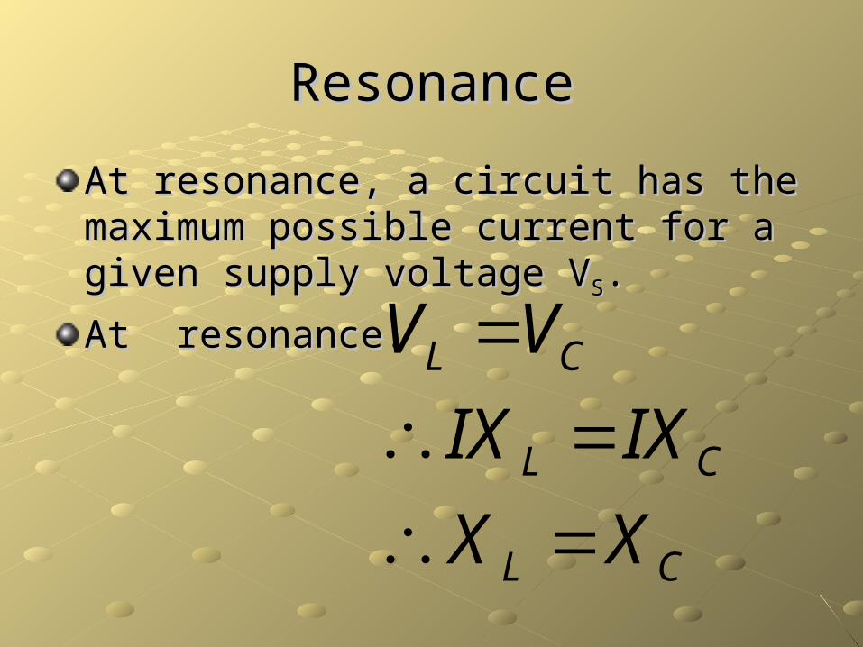
At resonance, a circuit has the maximum At resonance, a circuit has the maximum possible current for a given supply voltage possible current for a given supply voltage VVSS..
At resonance:At resonance:
CL
CL
CL
XX
IXIX
VV

Resonant FrequencyResonant Frequency
A circuit will have A circuit will have a resonant a resonant frequency ffrequency f00
which depends which depends on L and C:on L and C:
LCf
LCf
CfLf
XX CL
2
14
1
2
12
0
220
00

Rectifying ACRectifying AC
Rectifying – turning AC into DCRectifying – turning AC into DC
Putting a diode into the circuit will do this:Putting a diode into the circuit will do this:
t

Rectifying ACRectifying AC
A bridge rectifier will do this:A bridge rectifier will do this:
t

Rectifying ACRectifying AC
A bridge rectifier circuit looks like this:A bridge rectifier circuit looks like this:
240V AC in
12V AC out
12V DC(smoothing
cap)
Rectifying ACRectifying AC
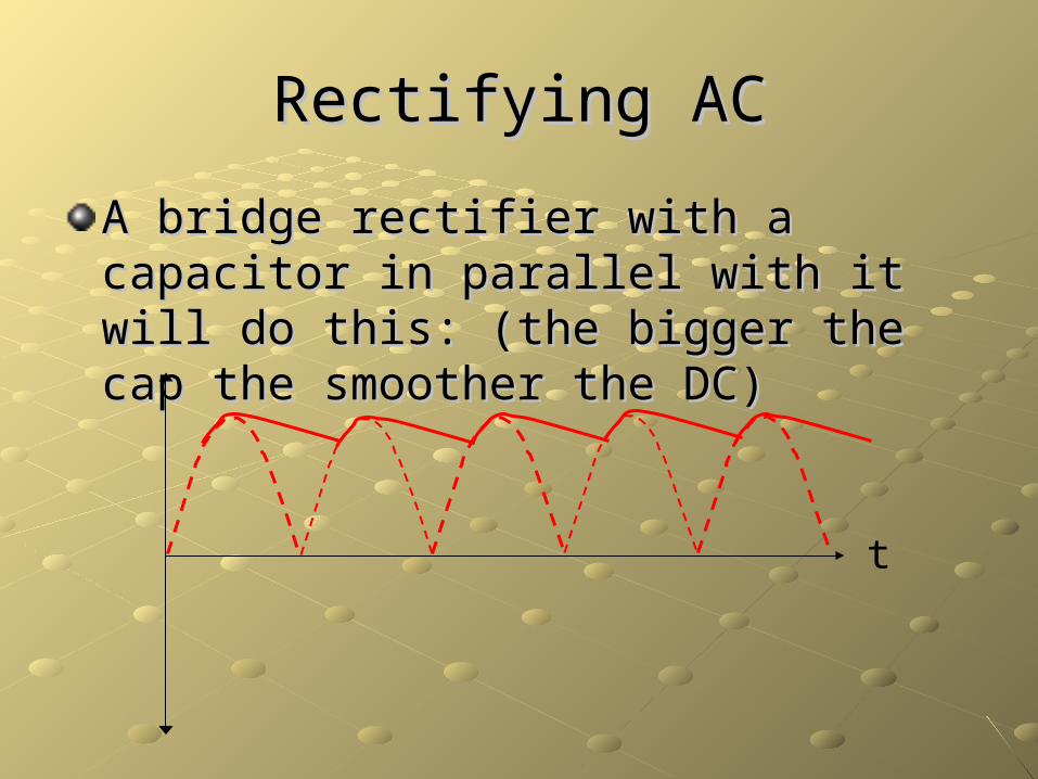
A bridge rectifier with a capacitor in A bridge rectifier with a capacitor in parallel with it will do this: (the bigger the parallel with it will do this: (the bigger the cap the smoother the DC)cap the smoother the DC)
t