alternating current circuits - wordpress.com · alternating current circuits answers to questions...
TRANSCRIPT

33
CHAPTER OUTLINE
33.1 AC Sources33.2 Resistors in an AC Circuit33.3 Inductors in an AC Circuit33.4 Capacitors in an AC Circuit33.5 The RLC Series Circuit33.6 Power in an AC Circuit33.7 Resonance in a Series RLC Circuit33.8 The Transformer and Power Transmission33.9 Rectifiers and Filters
Alternating Current Circuits
ANSWERS TO QUESTIONS
Q33.1 If the current is positive half the time and negative half thetime, the average current can be zero. The rms current is notzero. By squaring all of the values of the current, they allbecome positive. The average (mean) of these positive values isalso positive, as is the square root of the average.
Q33.2 ∆∆
VV
avg =max
2, ∆
∆V
Vrms =
max
2
Q33.3 AC ammeters and voltmeters read rms values. With anoscilloscope you can read a maximum voltage, or test whetherthe average is zero.
Q33.4 Suppose the voltage across an inductor varies sinusoidally.Then the current in the inductor will have its instantaneous
peak positive value 14
cycle after the voltage peaks. The voltage
is zero and going positive 14
cycle (90°) before the current is
zero and going positive.
Q33.5 If it is run directly from the electric line, a fluorescent light tube can dim considerably twice in everycycle of the AC current that drives it. Looking at one sinusoidal cycle, the voltage passes throughzero twice. We don’t notice the flickering due to a phenomenon called retinal imaging. We do notnotice that the lights turn on and off since our retinas continue to send information to our brainsafter the light has turned off. For example, most TV screens refresh at between 60 to 75 times persecond, yet we do not see the evening news flickering. Home video cameras record information atfrequencies as low as 30 frames per second, yet we still see them as continuous action. A vividdisplay of retinal imaging is that persistent purple spot you see after someone has taken a picture ofyou with a flash camera.
Q33.6 The capacitive reactance is proportional to the inverse of the frequency. At higher and higherfrequencies, the capacitive reactance approaches zero, making a capacitor behave like a wire. As thefrequency goes to zero, the capacitive reactance approaches infinity—the resistance of an opencircuit.
Q33.7 The second letter in each word stands for the circuit element. For an inductor L, the emf ε leads thecurrent I—thus ELI. For a capacitor C, the current leads the voltage across the device. In a circuit inwhich the capacitive reactance is larger than the inductive reactance, the current leads the sourceemf—thus ICE.
265

266 Alternating Current Circuits
Q33.8 The voltages are not added in a scalar form, but in a vector form, as shown in the phasor diagramsthroughout the chapter. Kirchhoff’s loop rule is true at any instant, but the voltages across differentcircuit elements are not simultaneously at their maximum values. Do not forget that an inductor caninduce an emf in itself and that the voltage across it is 90° ahead of the current in the circuit in phase.
Q33.9 In an RLC series circuit, the phase angle depends on the source frequency. At very low frequencythe capacitor dominates the impedance and the phase angle is near –90°. The phase angle is zero atthe resonance frequency, where the inductive and capacitive reactances are equal. At very highfrequencies φ approaches + °90 .
Q33.10 − °≤ ≤ °90 90φ . The extremes are reached when there is no significant resistance in the circuit.
Q33.11 The resistance remains unchanged, the inductive resistance doubles, and the capacitive reactance isreduced by one half.
Q33.12 The power factor, as seen in equation 33.29, is the cosine of the phase angle between the current andapplied voltage. Maximum power will be delivered if ∆V and I are in phase. If ∆V and I are 90° outof phase, the source voltage drives a net current of zero in each cycle and the average power is zero.
Q33.13 The person is doing work at a rate of P = Fv cosθ . One can consider the emf as the “force” thatmoves the charges through the circuit, and the current as the “speed” of the moving charges. Thecosθ factor measures the effectiveness of the cause in producing the effect. Theta is an angle in realspace for the vacuum cleaner and phi is the analogous angle of phase difference between the emfand the current in the circuit.
Q33.14 As mentioned in Question 33.5, lights that are powered by alternating current flicker or get slightlybrighter and dimmer at twice the frequency of the AC power source. Even if you tried using twobanks of lights, one driven by AC 180° of phase from the other, you would not have a stable lightsource, but one that exhibits a “ripple” in intensity.
Q33.15 In 1881, an assassin shot President James Garfield. The bullet was lost in his body. AlexanderGraham Bell invented the metal detector in an effort to save the President’s life. The coil is preservedin the Smithsonian Institution. The detector was thrown off by metal springs in Garfield’s mattress, anew invention itself. Surgeons went hunting for the bullet in the wrong place and Garfield died.
Q33.16 As seen in Example 33.8, it is far more economical to transmit at high voltage than at low voltage, asthe I R2 loss on the transmission line is significantly lower. Transmitting power at high voltagepermits the use of step-down transformers to make “low” voltages and high currents available to theend user.
Q33.17 Insulation and safety limit the voltage of a transmission line. For an underground cable, thethickness and dielectric strength of the insulation between the conductors determines the maximumvoltage that can be applied, just as with a capacitor. For an overhead line on towers, the designermust consider electrical breakdown of the surrounding air, possible accidents, sparking across theinsulating supports, ozone production, and inducing voltages in cars, fences, and the roof gutters ofnearby houses. Nuisance effects include noise, electrical noise, and a prankster lighting a hand-heldfluorescent tube under the line.
Q33.18 No. A voltage is only induced in the secondary coil if the flux through the core changes in time.

Chapter 33 267
Q33.19 This person needs to consider the difference between the power delivered by a power plant andI R2 losses in transmission lines. At lower voltages, transmission lines must carry higher currents totransmit the same power, as seen in Example 33.8. The high transmitted current at low voltageactually results in more internal energy production than a lower current at high voltage. In his
formula ∆V
Ra f2
, the ∆V does not represent the line voltage but the potential difference between the
ends of one conductor. This is very small when the current is small.
Q33.20 The Q factor determines the selectivity of the radio receiver. For example, a receiver with a very lowQ factor will respond to a wide range of frequencies and might pick up several adjacent radiostations at the same time. To discriminate between 102.5 MHz and 102.7 MHz requires a high-Qcircuit. Typically, lowering the resistance in the circuit is the way to get a higher quality resonance.
Q33.21 Both coils are wrapped around the same core so that nearly all of the magnetic flux created by theprimary passes through the secondary coil, and thus induces current in the secondary when thecurrent in the primary changes.
Q33.22 The frequency of a DC signal is zero, making the capacitive reactance at DC infinite. The capacitorthen acts as an open switch. An AC signal has a non-zero frequency, and thus the capacitivereactance is finite, allowing a signal to pass from Circuit A to Circuit B.
SOLUTIONS TO PROBLEMS
Section 33.1 AC Sources
Section 33.2 Resistors in an AC Circuit
P33.1 ∆ ∆ ∆v t V t V t t ta f b g b g a f a f a f= = = =max sin sin sin sinω ω π2 200 2 2 100 283 628rms V
P33.2 ∆Vrms V2
V= =170
120
(a) P = → = =∆
ΩV
RRrms V
W
b g a f2 212075 0
193.
(b) R = =120100
1442 V
W
a fΩ
P33.3 Each meter reads the rms value.
∆
∆Ω
V
IVR
rms
rmsrms
V2
V
V24.0
A
= =
= = =
10070 7
70 72 95
.
..
FIG. P33.3

268 Alternating Current Circuits
P33.4 (a) ∆ ∆v V tR = max sinω
∆ ∆v VR = 0 250. maxb g, so sin .ω t = 0 250 , or ω t = −sin .1 0 250a f.The smallest angle for which this is true is ω t = 0 253. rad Thus, if t = 0 010 0. s ,
ω = =0 253
25 3.
. rad
0.010 0 s rad s .
(b) The second time when ∆ ∆v VR = 0 250. maxb g, ω t = −sin .1 0 250a f again. For this occurrence,ω πt = − =0 253 2 89. . rad rad (to understand why this is true, recall the identitysin sinπ θ θ− =a f from trigonometry). Thus,
t = =2 89
0 114.
. rad
25.3 rad s s .
P33.5 i I tR = max sinω becomes 0 600 0 007 00. sin .= ωb g .Thus, 0 007 00 0 600 0 6441. sin . .b g a fω = =−
and ω π= =91 9 2. rad s f so f = 14 6. Hz .
P33.6 P = I Vrms rms∆b g and ∆Vrms V= 120 for each bulb (parallel circuit), so:
I IV1 2
1 1501 25= = = =
P∆ rms
W120 V
A. , and RVI
R11
2120
96 0= = = =∆
Ωrms V1.25 A
.
IV3
3 1000 833= = =
P∆ rms
W120 V
A. , and RVI3
3
120144= = =
∆Ωrms V
0.833 A .
P33.7 ∆Vmax .= 15 0 V and Rtotal = + =8 20 10 4 18 6. . .Ω Ω Ω
IV
RI
I R
maxmax .
.
.. .
= = = =
= =FHG
IKJ =
∆Ω
Ω
totalrms
speaker rms2
speaker
V18.6
A
A2
W
15 00 806 2
0 80610 4 3 38
2
P a f
Section 33.3 Inductors in an AC Circuit
P33.8 For Imax .= 80 0 mA , Irms mA2
mA= =80 0
56 6.
.
XVI
X fL LX
f
L
LL
b g
a f
min
.
.
= = =
= → = ≥ ≥
rms
rms
V0.056 6 A
2 20.0
H
50 0884
22
8847 03
Ω
Ωπ
π π
Chapter 33 269
P33.9 (a) XVIL = = =∆
Ωmax
max ..
1007 50
13 3
LXL= = = =ω π
13 32 50 0
0 042 4 42 4.
.. .a f H mH
(b) XVIL = = =∆
Ωmax
max ..
1002 50
40 0
ω = =×
=−XL
L 40 042 4 10
9423.
. rad s
P33.10 At 50.0 Hz, X LX
LL= =
FHG
IKJ = =2 50 0 2 50 0
2 60 050 060 0
54 0 45 060 0π ππ
. ..
.
.. .. Hz Hz
Hz Hza f a f a f a fΩ Ω
IVX
V
XL Lmax
max
..= = = =
∆ ∆
Ω
2 2 10045 0
3 14rms V
Ab g a f
.
P33.11 i tV
LtL a f
a f a fb gb ge j
= −FHGIKJ =
−
× −
∆ max sin. sin . .
. .ωω
π π π
π2
80 0 65 0 0 015 5 2
65 0 70 0 10 3
V
rad s H
i tL a f a f a f= =5 60 1 59 5 60. sin . . A rad A
P33.12 ω π π= = =2 2 60 0 377f . s rad sb gX L
IVX
I I
i t I t
U Li
L
L
= = ⋅ =
= = =
= = =
= = ⋅FHG
IKJ = °=
= = ⋅ =
ω
ωπ
377 0 020 0 7 54
12015 9
2 2 15 9 22 5
22 52 60 0
22 5 120 19 5
12
12
0 020 0 19 5 3 802 2
s V s A
V7.54
A
A A
As
1 s180
A A
V s A A J
rmsrms
rms
b gb g
a fa f a f a f a f
b ga f
. .
.
. .
sin . sin.
. sin .
. . .
max
max
Ω
∆Ω
P33.13 LN
IB=
Φ where ΦB is the flux through each turn. N LI
X V
XBL L
LΦ
∆, max max
, max= =
ωd i
NV
fBL
Φ∆
, .. max
, rms 2 V s2
T C mN s
N mJ
JV C
T m= =⋅ ⋅ ⋅
⋅FHG
IKJ
⋅FHGIKJ ⋅FHGIKJ = ⋅
2
2120
60 00 450
d ia fπ π
.

270 Alternating Current Circuits
Section 33.4 Capacitors in an AC Circuit
P33.14 (a) Xf CC =
12π
: 1
2 22 0 10175
6π f . ×<
−e j Ω
1
2 22 0 10 1756π . ×<
−e ja ff f > 41 3. Hz
(b) XCC ∝1
, so X X4412
22a f a f= : XC < 87 5. Ω
P33.15 I IV
XV f C
Cmax = = =2
22 2rms
rmsrms
∆∆
b g b g π
(a) Imax . .= × =−2 120 2 60 0 2 20 10 1416 V s C V mAa f b ge jπ
(b) Imax . .= × =−2 240 2 50 0 2 20 10 2356 V s F mAa f b ge jπ
P33.16 Q C V C V C Vmax max= = =∆ ∆ ∆b g b g b g2 2rms rms
P33.17 I V Cmax max . . .= = × =− −∆b g a fa fe je jω π48 0 2 90 0 3 70 10 1001 6 V s F mA
P33.18 XCC = =
×=
−
1 1
2 60 0 1 00 102 65
3ω π . ..
s C V b ge jΩ
v t V tC a f = ∆ max sinω , to be zero at t = 0
iVX
tCC
= + = + °LNM
OQP= °+ ° = −
−
−∆
Ωmax sin
.sin . . sin . .ω φ πb g a f a f a f2 120
2 652
60180
90 0 64 0 120 90 0 32 01
1
V
s s
A A
Section 33.5 The RLC Series Circuit
P33.19 (a) X LL = = × =−ω π2 50 0 400 10 1263.a fe j Ω
XC
Z R X X
V I Z
C
L C
= =×
=
= + − = + − =
= = × =
−
−
1 1
2 50 0 4 43 10719
500 126 719 776
250 10 776 194
6
2 2 2 2
3
ω π . .
max max
a fe jb g a fe ja f
V
Ω
Ω
∆ FIG. P33.19
(b) φ =−F
HGIKJ =
−FHG
IKJ = − °− −tan tan .1 1 126 719
50049 9
X XR
L C . Thus, the Current leads the voltage.
P33.20 ωω
ωLC LC
= → = =× ×
= ×− −
1 1 1
57 0 10 57 0 101 75 10
6 6
4
. ..
e je j rad s
f = =ωπ2
2 79. kHz

Chapter 33 271
P33.21 (a) X LL = = × =− −ω π2 50 0 250 10 78 51 3. . s H e je j Ω
(b) XCC = = × =− − −1
2 50 0 2 00 10 1 591 61
ωπ . . . s F ke je j Ω
(c) Z R X XL C= + − =2 2 1 52b g . kΩ
(d) IVZmaxmax= =
×=
∆Ω
210138
V1.52 10
mA3
(e) φ =−L
NMOQP = − = − °− −tan tan . .1 1 10 1 84 3
X XR
L C a f
P33.22 (a) Z R X XL C= + − = + − =2 2 2 268 0 16 0 101 109b g a f. . Ω
X L
XC
L
C
= = =
= =×
=−
ω
ω
100 0 160 16 01 1
100 99 0 10101
6
a fa f
a fe j
. .
.
Ω
Ω
(b) IVZmaxmax .
.= = =∆
Ω40 0
0 367 V
109 A
(c) tan.
..φ =
−=
−= −
X XR
L C 16 0 10168 0
1 25 :
φ = − = − °0 896 51 3. . rad
Imax .= 0 367 A ω = 100 rad s φ = − = − °0 896 51 3. . rad
P33.23 X f LL = = =2 2 60 0 0 460 173π π . .a fa f Ω
Xf CC = =
×=
−
12
1
2 60 0 21 0 10126
6π π . .a fe j Ω
(a) tan .φ =−
=−
=X X
RL C 173 126
0 314 150 Ω Ω
Ωφ = = °0 304 17 4. . rad
(b) Since X XL C> , φ is positive; so voltage leads the current .
*P33.24 For the source-capacitor circuit, the rms source voltage is ∆V Xs C= 25 1. mAa f . For the circuit with
resistor, ∆V R X Xs C C= + =15 7 25 12 2. . mA mAa f a f . This gives R XC= 1 247. . For the circuit with idealinductor, ∆V X X Xs L C C= − =68 2 25 1. . mA mAa f a f . So X X XL C C− = 0 368 0. . Now for the full circuit
∆V I R X X
X I X X
I
s L C
C C C
= + −
= +
=
2 2
2 225 1 1 247 0 368
19 3
b ga f b g b g. . .
.
mA
mA

272 Alternating Current Circuits
P33.25 Xf CC = =
×= ×
−
12
1
2 60 0 20 0 101 33 10
128
π π . ..
Hz F a fe jΩ
Z
IVZ
V I R
= × + × ≈ ×
= =×
= ×
= = × × =
−
−
50 0 10 1 33 10 1 33 10
5 0003 77 10
3 77 10 50 0 10 1 88
3 2 8 2 8
5
5 3
. . .
.
. . .
V1.33 10
A
A V
rmsrms
8
rms body rms body
Ω Ω Ω
∆Ω
∆ Ω
e j e j
b g e je j
P33.26 XCC = =
×=
−
1 1
2 50 0 65 0 1049 0
6ω π . ..a fe j
Ω
X L
Z R X X
IVZ
L
L C
= = × =
= + − = + − =
= = =
−ω π2 50 0 185 10 58 1
40 0 58 1 49 0 41 0
15041 0
3 66
3
2 2 2 2
. .
. . . .
..max
a fe jb g a f a f
Amax
Ω
Ω
∆
(a) ∆V I RR = = =max .3 66 40 146a fa f V
(b) ∆V I XL L= = = =max . . .3 66 58 1 212 5 212a fa f V
(c) ∆V I XC C= = = =max . . .3 66 49 0 179 1 179a fa f V V
(d) ∆ ∆V VL C− = − =212 5 179 1 33 4. . . V
FIG. P33.26
P33.27 R = 300 Ω
X LL = = FHGIKJ =−ω π
π2
5000 200 2001 s H .a f Ω
XCC = = F
HGIKJ ×
LNM
OQP =− −−
12
50011 0 10 90 91 6
1
ωπ
π s F . .e j Ω
Z R X XL C= + − =2 2 319b g Ω and
φ =−F
HGIKJ = °−tan .1 20 0
X XR
L C
XL = 200 Ω
XC = 90.9 ΩR = 300 Ω
φ
ZXL - XC = 109 Ω
FIG. P33.27
*P33.28 Let Xc represent the initial capacitive reactance. Moving the plates to half their original separation
doubles the capacitance and cuts XCC =
1ω
in half. For the current to double, the total impedance
must be cut in half: Z Zi f= 2 , R X X R XX
L C LC2 2 2
2
22
+ − = + −FHGIKJb g ,
R R X R RX
R RX X R RX X
X R
CC
C C C C
C
2 2 22
2 2 2 2
42
2 2 8 4
3
+ − = + −FHGIKJ
FHG
IKJ
− + = − +
=
b g

Chapter 33 273
P33.29 (a) XL = = ×2 100 20 5 1 29 104π Hz H a fa f. . Ω
ZVI
X X Z R
X XC
C
L C
L C
= = =
− = − = −
− = × − = ± =
∆Ω
Ω Ω
Ω Ω
rms
rms
V4.00 A
HznF or 124 nF
20050 0
50 0 35 0
1 29 101
2 10035 7 123
2 2 2 2 2
4
.
. .
. .
b g b g b g
b gπ
(b) ∆ ΩV I XL L, . . . rms rms A kV= = × =4 00 1 29 10 51 54a fe jNotice that this is a very large voltage!
FIG. P33.29
Section 33.6 Power in an AC Circuit
P33.30 X LL = = =ω 1 000 0 050 0 50 0s H b gb g. . Ω
XC
Z R X X
Z
C
L C
= = × =
= + −
= + − =
− −11 000 50 0 10 20 0
40 0 50 0 20 0 50 0
6 1
2 2
2 2
ωs F
b ge j
b ga f a f
. .
. . . .
Ω
Ω FIG. P33.30
(a) IVZrmsrms V
50.0 = =
∆
Ωb g 100
I
X XR
L C
rms A
40.0
=
=−F
HGIKJ
= = °
2 00
30 036 9
.
arctan
arctan.
.
φ
φ ΩΩ
(b) P = = °=∆V Irms rms V 2.00 A Wb g a fcos cos .φ 100 36 9 160
(c) PR I R= = =rms2 A W2 00 40 0 1602. .a f Ω
P33.31 ω = 1 000 rad s , R = 400 Ω , C = × −5 00 10 6. F , L = 0 500. H
∆Vmax = 100 V , ω L = 500 Ω ,1
200ωCFHGIKJ = Ω
Z R LC
IVZ
= + −FHG
IKJ = + =
= = =
22
2 21400 300 500
100500
0 200
ωω
A
Ω
∆max
max .
The average power dissipated in the circuit is P = =FHGIKJI R
IRrms
2 max2
2.
P = =0 200
2400 8 00
2..
A W
a f a fΩ

274 Alternating Current Circuits
P33.32 Z R X XL C= + −2 2b g or X X Z RL C− = −b g 2 2
X X
X XR
IVZ
V I
L C
L C
− = − =
=−F
HGIKJ =
FHG
IKJ = °
= = =
= = ° =
− −
b g a f a f
b g a fa f a f
75 0 45 0 60 0
60 053 1
2102 80
210 2 80 53 1 353
2 2
1 1
. . .
tan tan.
.
.
cos . cos .
45.0
V75.0
A
V A W
rmsrms
rms rms
Ω Ω Ω
ΩΩ
∆Ω
∆
φ
φP
P33.33 (a) P = = − ° = ×I Vrms rms W∆b g a f a fcos . cos . .φ 9 00 180 37 0 1 29 103
P = I Rrms2 so 1 29 10 9 003 2. .× = a f R and R = 16 0. Ω .
(b) tanφ =−X XR
L C becomes tan .− ° =−
37 016
a f X XL C : so X XL C− = −12 0. Ω .
P33.34 X LL = = =ω π2 60 0 0 025 0 9 42. . .s H b gb g Ω
Z R X XL C= + − = + =2 2 2 220 0 9 42 22 1b g a f a f. . . Ω Ω
(a) IVZrmsrms V
22.1 A= = =
∆Ω
1205 43.
(b) φ = FHGIKJ = °−tan
..
.1 9 4220 0
25 2 so power factor = =cos .φ 0 905 .
(c) We require φ = 0 . Thus, X XL C= : 9 421
2 60 0 1.
.
sΩ =
−π e jCand C = 281 Fµ .
(d) P Pb d= or ∆∆
V IV
Rb b bd
rms rmsrmsb g b g b g
cosφ =2
∆ ∆ ΩV R V Id b b brms rms rms V A Vb g b g b g a fa fa fa f= = =cos . . .φ 20 0 120 5 43 0 905 109
P33.35 Consider a two-wire transmission line:
IVrms
rms=
P∆
and power loss = =I Rrms2
lineP
100.
Thus, P P
∆VR
rms
FHG
IKJ =
2
12100
b g or RV
1
2
200=
∆ rmsb gP
Rd
AV
1
2
200= =ρ ∆ rmsb g
Por A
r d
V= =π ρ2
42002
2
a fb g
P
∆ rms
and the diameter is 2800
2rd
V=
ρ
π
P
∆a f .
R1
R1
RL∆Vrms
FIG. P33.35

Chapter 33 275
P33.36 One-half the time, the left side of the generator is positive, the topdiode conducts, and the bottom diode switches off. The powersupply sees resistance
12
12
1
R RR+LNM
OQP =−
and the power is ∆V
Rrmsb g2
.
The other half of the time the right side of the generator is positive,the upper diode is an open circuit, and the lower diode has zeroresistance. The equivalent resistance is then
R RR R
Req = + +LNM
OQP =−1
31 7
4
1
and P = =∆ ∆V
RV
Rrms
eq
rmsb g b g2 247
.
~V∆
RR R
R2
FIG. P33.36
The overall time average power is:∆ ∆ ∆V R V R V
R
rms rms rmsb g b g b g2 2 24 7
211
14
+= .
Section 33.7 Resonance in a Series RLC Circuit
P33.37 ω π06 82 99 7 10 6 26 10
1= × = × =. .e j rad s
LC
CL
= =× ×
=−
1 1
6 26 10 1 40 101 82
02 8 2 6ω . .
.e j e j
pF
P33.38 At resonance, 1
22
ππ
f Cf L= and
1
22π f L
Cb g
= .
The range of values for C is 46 5. pF to 419 pF .
*P33.39 (a) fLC
=1
2π
Cf L
= =×
FHGIKJ = ×
−
−14
1
4 10 400 106 33 102 2 2 10 2 12
13
π π
A
s Vs
CAs
Fe j
.
(b) CA
d d=
∈=
∈κ κ0 02
=∈FHGIKJ =
× ×× ×
FHG
IKJ = ×
− −
−−Cd
κ 0
1 2 13 3
12
1 236 33 10 10
108 46 10
..
F mm1 8.85 F
m
(c) X f LL = = × × × =−2 2 10 400 10 25 110 12π π s Vs A . Ω

276 Alternating Current Circuits
P33.40 L = 20 0. mH , C = × −1 00 10 7. , R = 20 0. Ω , ∆Vmax = 100 V
(a) The resonant frequency for a series –RLC circuit is fLC
= =1
21
3 56π
. kHz .
(b) At resonance, IVRmaxmax .= =
∆5 00 A .
(c) From Equation 33.38, QL
R= =ω 0 22 4. .
(d) ∆V X I LIL L, max max . max kV= = =ω 0 2 24
P33.41 The resonance frequency is ω 01
=LC
. Thus, if ω ω= 2 0 ,
X LLC
LLCL = =
FHGIKJ =ω
22 and X
CLCC
LCC = = =
12
12ω
Z R X X RLCL C= + − = + FHGIKJ
2 2 2 2 25b g . so IVZ
V
R L Crms
rms rms= =+
∆ ∆2 2 25. b g
and the energy delivered in one period is E t= P ∆ :
EV R
R L C
V RC
R C LLC
V RC LC
R C L=
+FHGIKJ = +
=+
∆ ∆ ∆rms rms rmsb gb g
b g e j b g2
2
2
2
2
22 252
2 25
4
4 9 00. . .πω
ππ
.
With the values specified for this circuit, this gives:
E =× ×
× + ×=
− −
− −
4 50 0 10 0 100 10 10 0 10
4 10 0 100 10 9 00 10 0 10242
2 6 3 2 3 1 2
2 6 3
π . . .
. . .
V F H
F H mJ
a f a fe j e ja f e j e j
Ω
Ω.
P33.42 The resonance frequency is ω 01
=LC
. Thus, if ω ω= 2 0 ,
X LLC
LLCL = =
FHGIKJ =ω
22 and X
CLCC
LCC = = =
12
12ω
.
Then Z R X X RLCL C= + − = + FHGIKJ
2 2 2 2 25b g . so IVZ
V
R L Crms
rms rms= =+
∆ ∆2 2 25. b g
and the energy delivered in one period is
E tV R
R L C
V RC
R C LLC
V RC LC
R C L= =
+FHGIKJ = +
=+
P∆∆ ∆ ∆rms rms rmsb gb g
b g e j b g2
2
2
2
2
22 252
2 25
4
4 9 00. . .πω
ππ
.

Chapter 33 277
P33.43 For the circuit of Problem 22, ω 03 6
1 1
160 10 99 0 10251= =
× ×=
− −LC H F rad s
e je j.
QL
R= =
×=
−ω 0
3251 160 10
68 00 591
rad s H
b ge j.
.Ω
.
For the circuit of Problem 23, QL
RL
R LC RLC
= = = =××
=−
−ω 0
3
61 1
150460 10
100 987
H
21.0 FΩ. .
The circuit of Problem 23 has a sharper resonance.
Section 33.8 The Transformer and Power Transmission
P33.44 (a) ∆V21
13120 9 23, rms V V= =a f .
(b) ∆ ∆V I V I1 1 2 2, , , , rms rms rms rms=
120 0 350 9 23 2 V A V , rmsa fa f a f. .= I
I242 0
4 55,.
. rms W
9.23 V A= = for a transformer with no energy loss.
(c) P = 42 0. W from part (b).
P33.45 ∆ ∆VNN
Vout in V Vb g b g a fmax max= = FHG
IKJ =2
1
2 000350
170 971
∆Vout rms
V Vb g a f
= =971
2687
P33.46 (a) ∆ ∆VNN
V22
11, rms , rmsd i d i= N2
2 200 80
1101 600= =
b ga f windings
(b) I V I V1 1 2, rms , rms , rms 2, rms∆ ∆d i d i= I1, rms A= =1 50 2 200
11030 0
..
a fb g
(c) 0 950 1 2. I V I V, rms 1, rms , rms 2, rms∆ ∆d i d i= I11 20 2 200
110 0 95025 3,
.
.. rms A= =
a fb ga f

278 Alternating Current Circuits
P33.47 The rms voltage across the transformer primary is
NN
V1
2∆ 2, rmsd i
so the source voltage is ∆ ∆V I RNN
Vs s, rms , rms , rms= +11
22d i .
The secondary current is ∆V
RL
2, rmsd i, so the primary current is
NN
V
RI
L
2
1
21
∆ , rms, rms
d i= .
FIG. P33.47
Then ∆∆ ∆
VN V R
N R
N V
Nss
L, rms
, rms , rms= +
2 2
1
1 2
2
d i d i
and RN R
N VV
N V
NsL
s= −FHGG
IKJJ= −
FHG
IKJ =
1
2 2
1 2
2
5 50 02 25 0
80 05 25 0
287 5
∆∆
∆ ΩΩ
, rms, rms
rms V
V V
d id i a f
a fa f, .
..
.. .
P33.48 (a) ∆ ∆VNN
V22
11, rms , rms= d i N
N
V
V2
1
2
1
310 0 1083 3= =
×=
∆
∆,
,
.. rms
rms
V120 V
(b) I V I V2 2 0 900, rms , rms 1, rms 1, rms∆ ∆d i d i= .
I2, rms V V
24.0 V10 0 10 0 900
1201203. .× = F
HGIKJe j a f
ΩI2, rms mA= 54 0.
(c) ZV
I22
2
310 0 10185= =
×=
∆Ω, rms
, rms
V0.054 A
k.
P33.49 (a) R = × × =−4 50 10 6 44 10 2904 5. . M m Ω Ωe je j and IVrms
rms5 W
5.00 10 V A= =
××
=P
∆5 00 10
10 06.
.
Ploss rms2 A kW= = =I R 10 0 290 29 02. .a f a fΩ
(b)PPloss =
××
= × −2 90 105 00 10
5 80 104
63.
..
(c) It is impossible to transmit so much power at such low voltage. Maximum power transferoccurs when load resistance equals the line resistance of 290 Ω , and is
4 50 10
2 2 29017 5
3 2.
.×
⋅=
V
kW
e ja fΩ far below the required 5 000 kW.

Chapter 33 279
Section 33.9 Rectifiers and Filters
*P33.50 (a) Input power = 8 W
Useful output power = = =I V∆ 0 3 2 7. . A 9 V Wa fefficiency = = = =
useful outputtotal input
W8 W
2 70 34 34%
..
(b) Total input power = Total output power
8 2 7
5 3
W W wasted power
wasted power W
= +
=
.
.
(c) E t= = FHG
IKJFHGIKJ = ×
×
FHG
IKJ =P ∆ 8 31
86 4001 29 10 88 W 6 d
s1 d
1 J1 Ws
J$0.135
3.6 10 J6a fa f . $4.
*P33.51 (a) The input voltage is ∆V IZ I R X I RCCin = = + = +FHGIKJ
2 2 22
1ω
. The output voltage is
∆V IRout = . The gain ratio is ∆∆VV
IR
I R C
R
R C
out
in=
+=
+2 2 2 21 1ω ωb g b g.
(b) As ω → 0 , 1
ωC→∞ and
∆∆VV
out
in→ 0
As ω →∞ , 1
0ωC
→ and ∆∆VV
RR
out
in→ = 1
(c)12 12 2=
+
R
R Cωb g
RC
R22 2
214+ =
ωω 2 2
21
3C
R= ω π= =2
13
fRC
fRC
=1
2 3π
P33.52 (a) The input voltage is ∆V IZ I R X I R CCin = = + = +2 2 2 21 ωb g . The output voltage is
∆V IXICCout = =
ω. The gain ratio is
∆∆VV
I C
I R C
C
R C
out
in=
+=
+
ω
ω
ω
ω2 2 2 21
1
1b g b g.
(b) As ω → 0 , 1
ωC→∞ and R becomes negligible in comparison. Then
∆∆VV
CC
out
in→ =
11
1ωω
. As
ω →∞ , 1
0ωC
→ and ∆∆VV
out
in→ 0 .
(c)12
1
12 2=
+
ω
ω
C
R Cb gR
C C2
2
2 21 4
+FHGIKJ =
ω ωR C2 2 2 3ω = ω π= =2
3f
RC
fRC
=3
2π

280 Alternating Current Circuits
P33.53 For this RC high-pass filter, ∆∆VV
R
R XC
out
in=
+2 2.
(a) When ∆∆VV
out
in= 0 500. ,
then 0 500
0 5002 2
..
0.500
Ω
Ωa f +=
XC
or XC = 0 866. Ω .
If this occurs at f = 300 Hz, the capacitance is
Cf XC
= = = × =−12
12 300 0 866
6 13 10 6134
π πµ
Hz F Fa fa f.
.Ω
.
(b) With this capacitance and a frequency of 600 Hz,
XC =×
=−
1
2 600 6 13 100 433
4π Hz F a fe j.
. Ω
∆∆
Ω
Ω Ω
VV
R
R XC
out
in
0.500 =
+=
+=
2 2 2 2
0 500
0 4330 756
.
..
a f a f.
FIG. P33.53
P33.54 For the filter circuit, ∆∆VV
X
R XC
C
out
in=
+2 2.
(a) At f = 600 Hz, Xf CC = =
×= ×
−
12
1
2 600 8 00 103 32 10
94
π π Hz F a fe j.
. Ω
and∆∆
Ω
Ω Ω
VV
out
in
90.0 =
×
+ ×≈
3 32 10
3 32 101 00
4
2 4 2
.
..
a f e j.
(b) At f = 600 kHz , Xf CC = =
× ×=
−
12
1
2 600 10 8 00 1033 2
3 9π π Hz F
e je j.. Ω
and∆∆
Ω
Ω Ω
VV
out
in
90.0 .2 =
+=
33 2
330 346
2 2
..
a f a f.
Chapter 33 281
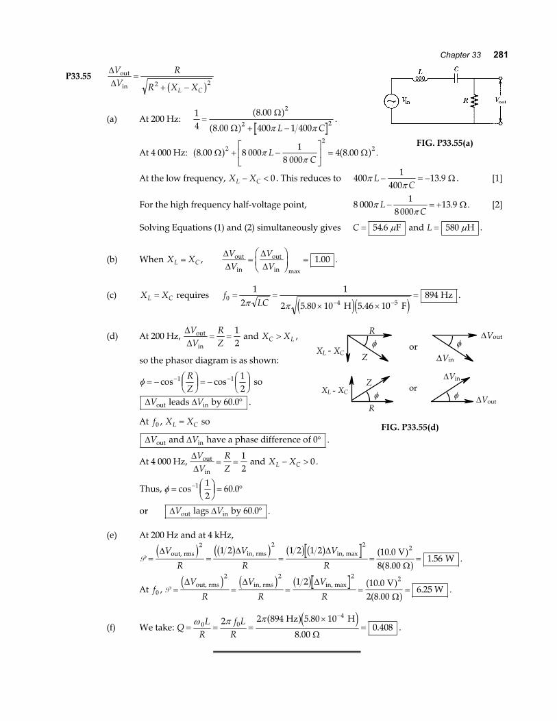
P33.55∆∆VV
R
R X XL C
out
in=
+ −2 2b g
(a) At 200 Hz:14
8 00
8 00 400 1 400
2
2 2=+ −
.
.
Ω
Ω
a fa f π πL C
.
At 4 000 Hz: 8 00 8 0001
8 0004 8 002
22. . Ω Ωa f a f+ −
LNM
OQP
=ππ
LC
.FIG. P33.55(a)
At the low frequency, X XL C− < 0 . This reduces to 4001
40013 9π
πL
C− = − . Ω . [1]
For the high frequency half-voltage point, 8 0001
8 00013 9π
πL
C− = + . Ω . [2]
Solving Equations (1) and (2) simultaneously gives C = 54 6. Fµ and L = 580 Hµ .
(b) When X XL C= ,∆∆
∆∆
VV
VV
out
in
out
in=FHGIKJ =
max
.1 00 .
(c) X XL C= requires fLC0
4 5
12
1
2 5 80 10 5 46 10894= =
× ×=
− −π π . . H F Hz
e je j.
(d) At 200 Hz, ∆∆VV
RZ
out
in= =
12
and X XC L> ,
so the phasor diagram is as shown:
φ = − FHGIKJ = −
FHGIKJ
− −cos cos1 1 12
RZ
so
∆ ∆V Vout in leads by 60.0° .
At f0 , X XL C= so
R
ZXL - XC
φ or φ∆Vout
∆Vin
R
ZXL - XC φ
orφ ∆Vout
∆Vin
FIG. P33.55(d)∆ ∆V Vout in and have a phase difference of 0° .
At 4 000 Hz, ∆∆VV
RZ
out
in= =
12
and X XL C− > 0 .
Thus, φ = FHGIKJ = °−cos .1 1
260 0
or ∆ ∆V Vout in lags by 60.0° .
(e) At 200 Hz and at 4 kHz,
P = = = = =∆ ∆ ∆
Ω
V
R
V
R
V
Rout, rms in, rms in, max V
W
d i b gd i b g b g a fa f
2 2 2 21 2 1 2 1 2 10 08 8 00
1 56..
. .
At f0 , P = = = = =∆ ∆ ∆
Ω
V
R
V
R
V
Rout, rms in, rms in, max V
.25 W
d i d i b g a fa f
2 2 2 21 2 10 02 8 00
6..
.
(f) We take: QL
Rf L
R= = =
×=
−ω π π
0 04
2 2 894 5 80 10
8 000 408
Hz H
a fe j.
..
Ω.

282 Alternating Current Circuits
Additional Problems
P33.56 The equation for ∆v ta f during the first period (using y mx b= + ) is:
∆∆
∆
∆ ∆∆
v tV tT
V
vT
v t dtV
T Tt dt
T T
a f b g
a f a f b g= −
= = −LNMOQPz z
2
1 212 2
0
2 2
0
maxmax
max
ave FIG. P33.56
∆∆ ∆ ∆
∆ ∆∆ ∆
vV
TT t T V V
V vV V
t
t T
a f b g b g a f a f b g
a f b g
22 3
0
23 3
2
22
2
2 1
3 61 1
3
3 3
ave
rmsave
max
= FHGIKJ
−= + − − =
= = =
=
=
max max max
max
P33.57 ω 06
11 1
0 050 0 5 00 102 000= =
×=
−
−
LC . . H F s
b ge jso the operating angular frequency of the circuit is
ωω
= = −0 1
21 000 s .
Using Equation 33.37, P =+ −
∆V R
R L
rmsb ge j
2 2
2 2 2 202 2
ω
ω ω ω
P =+ − ×
=400 8 00 1 000
8 00 1 000 0 050 0 1 00 4 00 1056 7
2 2
2 2 2 6 2
a f a fb ga f b g b g a f
.
. . . .. W .
Q ≈ 12 5.b g
FIG. P33.57
*P33.58 The angular frequency is ω π= =2 60 377s s . When S is open, R, L, and C are in series with thesource:
R X XVIL C
s2 22 2
4201 194 10+ − = FHG
IKJ = FHG
IKJ = ×b g ∆
Ω V
0.183 A 2. . (1)
When S is in position 1, a parallel combination of two R’s presents equivalent resistance R2
, in series
with L and C:
RX XL C2
204 504 10
22
23F
HGIKJ + − = FHG
IKJ = ×b g V
0.298 A 2. Ω . (2)
When S is in position 2, the current by passes the inductor. R and C are in series with the source:
R XC2 2
2420
2 131 10+ = FHGIKJ = ×
V0.137 A
2. Ω . (3)
Take equation (1) minus equation (2):
34
7 440 102 3R = ×. 2Ω R = 99 6. Ω
continued on next page

Chapter 33 283
(only the positive root is physical.) Now equation (3) gives
XCC = × − = =2 131 10 99 6 106 7
14 2 1 2. . .a f Ω Ω
ω (only the positive root is physical.)
C X CC= = = × =− − −ωb g b g1 1 5377 106 7 2 49 10s F. .Ω .
Now equation (1) gives
X X
X L
LX
L
L C
L
L
− = ± × − = ±
= + = =
= = =
1 194 10 99 6 44 99
106 7 44 99 61 74
0 164
4 2 1 2. . .
. . .
.
a f
or 151.7
H or 0.402 H
Ω Ω
Ω Ω Ω Ω ω
ω
P33.59 The resistance of the circuit is RVI
= = =∆
Ω12 0
19 0.
. V
0.630 A .
The impedance of the circuit is ZVI
= = =∆
Ωrms
rms
V0.570 A
24 0
42 1.
. .
Z R L
L Z R
2 2 2 2
2 2 2 21 1377
42 1 19 0 99 6
= +
= − = − =
ω
ω. . .a f a f mH
*P33.60 The lowest-frequency standing-wave state is NAN. The distance between the clamps we represent
as L d= =NNλ2
. The speed of transverse waves on the string is v fT
f L= = =λµ
2 . The magnetic
force on the wire oscillates at 60 Hz, so the wire will oscillate in resonance at 60 Hz.
TL
0 01960 4
2 2
. kg ms= b g T L= 274 2 kg ms2e j
Any values of T and L related according to this expression will work, includingif m NL T= =0 200 10 9. . . We did not need to use the value of the current and magnetic field. If
we assume the subsection of wire in the field is 2 cm wide, we can find the rms value of themagnetic force:
F I B TB = = °=sin . . sin .θ 9 0 02 0 015 3 90 2 75 A m mNa fa fb g .
So a small force can produce an oscillation of noticeable amplitude if internal friction is small.
P33.61 (a) When ω L is very large, the bottom branch carries negligible current. Also, 1
ωC will be
negligible compared to 200 Ω and 45 0
225. V
200 mA
Ω= flows in the power supply and the
top branch.
(b) Now 1
ωC→∞ and ω L→ 0 so the generator and bottom branch carry 450 mA .

284 Alternating Current Circuits
P33.62 (a) With both switches closed, the current goes only through generatorand resistor.
i tVR
ta f = ∆ max cosω
(b) P =12
2∆V
Rmaxb g
(c) i tV
R Lt
LR
a f =+
+ FHGIKJ
LNM
OQP
∆ max cos arctan2 2 2ω
ωω
FIG. P33.62
(d) For 010 0= =
−FHG
IKJφ
ω ωarctan
L C
Rb g
.
We require ωω0
0
1L
C= , so C
L=
1
02ω
.
(e) At this resonance frequency, Z R= .
(f) U C V CI XC C= =12
12
2 2 2∆b g
U CI X CV
R C
V L
RCmax maxmax max= = =
12
12
12
2 22
202 2
2
2
∆ ∆b g b gω
(g) U LI LV
Rmax maxmax= =
12
12
22
2
∆b g
(h) Now ω ω= =22
0 LC.
So φω ω
=−F
HGIKJ =
−FHG
IKJ=
FHG
IKJarctan arctan arctan
L C
R
L C L C
R RLC
1 2 1 2 32
b g b g.
(i) Now ωω
LC
=12
1ω
ω= =
12 2
0
LC.
P33.63 (a) IVRR , . rmsrms V
80.0 A= = =
∆Ω
1001 25
(b) The total current will lag the applied voltage as seen in the phasor
diagram at the right.
IVXL
L, rms
rms V
2 60.0 s H A= = =
−
∆ 100
0 2001 33
1π e ja f..
Thus, the phase angle is: φ =FHG
IKJ =
FHG
IKJ = °− −tan tan
..,1 1 1 33
46 7I
IL
R
rms
, rms
A1.25 A
.
φ
IR
IL
∆V
I
FIG. P33.63

Chapter 33 285
P33.64 Suppose each of the 20 000 people uses an average power of 500 W. (This means 12 kWh per day, or$36 per 30 days at 10¢ per kWh). Suppose the transmission line is at 20 kV. Then
IVrms
rms
W
V A= =
P∆
20 000 500
20 000103b ga f
~ .
If the transmission line had been at 200 kV, the current would be only ~102 A .
P33.65 R = 200 Ω , L = 663 mH , C = 26 5. Fµ , ω = −377 1 s , ∆Vmax .= 50 0 V
ω L = 250 Ω , 1
100ωCFHGIKJ = Ω , Z R X XL C= + − =2 2 250b g Ω
(a) IVZmaxmax .
.= = =∆
Ω50 0
0 200 V
250 A
φ =−F
HGIKJ = °−tan .1 36 8
X XR
L C ( ∆V leads I)
(b) ∆V I RR , max V= =max .40 0 at φ = °0
(c) ∆VI
CC ,max . max V= =ω
20 0 at φ = − °90 0. (I leads ∆V )
(d) ∆V I LL , max . max V= =ω 50 0 at φ = + °90 0. ( ∆V leads I)
P33.66 L = 2 00. H , C = × −10 0 10 6. F , R = 10 0. Ω , ∆v t ta f b g= 100 sinω
(a) The resonant frequency ω 0 produces the maximum current and thus the maximum powerdelivery to the resistor.
ω 06
1 1
2 00 10 0 10224= =
×=
−LC . .a fe j rad s
(b) P = = =∆V
Rmax
.b g a f
a f2 2
2100
2 10 0500 W
(c) IVZ
V
R L Crms
rms rms= =+ −
∆ ∆
2 21ω ωb gd i
and IVRrmsrmsb gmax
=∆
I R I Rrms2
rms2=
12 e jmax
or∆ ∆V
ZR
V
RRrms rmsb g b g2
2
2
212
= .
This occurs where Z R2 22= : R LC
R22
212+ −
FHG
IKJ =ω
ω
ω ω ω4 2 2 2 2 2 22 1 0L C L C R C− − + = or L C LC R C2 2 4 2 2 22 1 0ω ω− + + =e j2 00 10 0 10 2 2 00 10 0 10 10 0 10 0 10 1 02 6 2 4 6 2 6 2 2. . . . . .a f e j a fe j a f e j×LNM
OQP − × + ×LNM
OQP + =− − −ω ω .
Solving this quadratic equation, we find that ω 2 51 130= , or 48 894
ω 1 48 894 221= = rad s and ω 2 51 130 226= = rad s .

286 Alternating Current Circuits
P33.67 (a) From Equation 33.41,NN
VV
1
2
1
2=∆∆
.
Let input impedance ZVI1
1
1=∆
and the output impedance ZVI2
2
2=∆
so thatNN
Z IZ I
1
2
1 1
2 2= . But from Eq. 33.42,
II
VV
NN
1
2
2
1
2
1= =∆∆
.
So, combining with the previous result we have NN
ZZ
1
2
1
2= .
(b)NN
ZZ
1
2
1
2
8 0008 00
31 6= = =.
.
P33.68 P I RVZ
R= = FHGIKJrms
2 rms∆ 2
, so 250120
40 02
2 W V
=a f a f
Z. Ω : Z R L
C= + −
FHG
IKJ
22
1ω
ω
250120 40 0
40 0 2 0 185 1 2 65 0 10
2
2 62=
+ − × −
a f a fa f a f e j
.
. . .π πf fand 250
576 000
1 600 1 162 4 2 448 5
2
2 2 2=+ −
f
f f. .e j
12 304
1 600 1 351 1 5 692 3 5 995 300
2
2 4 2=+ − +
ff f f. .
so 1 351 1 6 396 3 5 995 300 04 2. .f f− + =
f 226 396 3 6 396 3 4 1 351 1 5 995 300
2 1 351 13 446 5 1 287 4=
± −=
. . .
.. .
b g b gb gb g or
f = 58 7. Hz or 35.9 Hz
P33.69 IVRR =
∆ rms ; IV
LL =∆ rms
ω; I
V
CC = −
∆ rms
ωb g 1
(a) I I I I VR
CLR C Lrms rms= + − = F
HGIKJ + −FHG
IKJ
2 22
21 1b g ∆ ω
ω
(b) tanφ =−
= −LNM
OQPFHG
IKJ
I II
VX X V R
C L
R C L∆
∆rmsrms
1 1 1
tanφ = −LNM
OQP
RX XC L
1 1FIG. P33.69

Chapter 33 287
P33.70 (a) I VR
CLrms rms= + −
FHG
IKJ∆
1 12
2
ωω
∆ ∆V Vrms rms→ b gmax when ω
ωC
L=
1
fLC
= =× ×
=− −
12
1
2 200 10 0 150 10919
3 6π π H F Hz
.e j
(b) IVRR = = =
∆Ω
rms V80.0
A120
1 50.
IV
LL = = =−
∆ rms V
374 s H A
ω120
0 2001 60
1e ja f..
I V CC = = × =− −∆ rms V s F mAωb g a fe je j120 374 0 150 10 6 731 6. .
(c) I I I IR C Lrms A= + − = + − =2 2 2 21 50 0 006 73 1 60 2 19b g a f b g. . . .
(d) φ =−L
NMOQP=
−LNM
OQP = − °− −tan tan
. ..
.1 1 0 006 73 1 601 50
46 7I I
IC L
R
The current is lagging the voltage .
FIG. P33.70
P33.71 (a) X XL C= = 1 884 Ω when f = 2 000 Hz
LX
fL= = =
21 884
0 150π π
4 000 rad s
HΩ
. and
Cf XC
= = =1
21
4 000 1 88442 2
π πb g b gb g rad s nF
Ω.
X fL = 2 0 150π . Ha f Xf
C =× −
1
2 4 22 10 8πb ge j. F
Z X XL C= + −40 0 2 2. Ωa f b g
f X X ZL C (Hz) 300600800
1 0001 5002 0003 0004 0006 000
10 000
283565754942
1 4101 8802 8303 7705 6509 420
12 6006 2804 7103 7702 5101 8801 260
942628377
1 23005 7203 9602 8301 100
401 5702 8305 0209 040
( ) ( ) ( )Ω Ω Ω
(b) Impedence, Ω
FIG. P33.71(b)

288 Alternating Current Circuits
P33.72 ω 061
1 00 10= = ×LC
. rad s
For each angular frequency, we find
Z R L C= + −2 21ω ωb g
then IZ
=1 00. V
and P = I 2 1 00. Ωa f .The full width at half maximum is:
∆∆
∆
f
f
= =−
=×
=−
ωπ
ωπ
π
2
1 000 5 0 999 5
21 00 10
2159
0
3 1
. .
.
b g
s Hz
while
RL2
1 00159
3π π=
×=
−
.
2 1.00 10 H Hz
Ω
e j.
ωω
ωω0
2LC
Z P I R 1
W
0.99900.99910.99930.99950.99970.99991.00001.00011.00031.00051.00071.00091.0010
999.0 999.1 999.3 999.5 999.7 999.910001000.11000.31000.51000.71000.91001
1001.01000.91000.71000.51000.31000.11000.0 999.9 999.7 999.5 999.3 999.1 999.0
2.242.061.721.411.171.021.001.021.171.411.722.062.24
0.199840.235690.337680.499870.735240.961531.000000.961540.735350.500120.337990.236010.20016
Ω Ω Ωa f a f a f a f=
1.0
0.8
0.6
0.4
0.2
0.00.996 0.998 1 1.002 1.004
I R2
(W)
ω/ω 0
FIG. P33.72
P33.73∆∆VV
R
R C
R
R f C
out
in=
+=
+2 2 2 21 1 2ω πb g b g
(a)∆∆VV
out
in=
12
when 1
3ωC
R= .
Hence, fRC
= = =ωπ π2
12 3
1 84. kHz .
∆Vin R
C
∆Vout
FIG. P33.73
continued on next page

Chapter 33 289
(b) Log Gain versus Log Frequency
–4
–3
–2
–1
0
0 1 2 3 4 5 6
Log f
Log ∆Vout/∆Vin
FIG. P33.73(b)
ANSWERS TO EVEN PROBLEMS
P33.2 (a) 193 Ω ; (b) 144 Ω P33.32 353 W
P33.34 (a) 5 43. A; (b) 0 905. ; (c) 281 Fµ ; (d) 109 VP33.4 (a) 25.3 rad/s; (b) 0.114 s
P33.3611
14
2∆VRrmsb gP33.6 1 25. A and 96 0. Ω for bulbs 1 and 2;
0 833. A and 144 Ω for bulb 3
P33.8 7 03. H or more P33.38 46 5. pF to 419 pF
P33.10 3 14. A P33.40 (a) 3 56. kHz; (b) 5 00. A ; (c) 22 4. ;(d) 2 24. kV
P33.12 3.80 J
P33.424
4 9
2
2
π ∆V RC LC
R C Lrmsb g
+P33.14 (a) greater than 41 3. Hz ;
(b) less than 87 5. Ω
P33.44 (a) 9 23. V ; (b) 4 55. A ; (c) 42 0. WP33.16 2C V∆ rmsb g
P33.46 (a) 1 600 turns ; (b) 30 0. A ; (c) 25 3. AP33.18 –32.0 A
P33.48 (a) 83 3. ; (b) 54 0. mA; (c) 185 kΩP33.20 2 79. kHz
P33.50 (a) 0.34; (b) 5.3 W; (c) $4.8P33.22 (a) 109 Ω ; (b) 0 367. A ; (c) Imax .= 0 367 A ,
ω = 100 rad s, φ = −0 896. rad P33.52 (a) see the solution; (b) 1; 0; (c) 3
2π RCP33.24 19.3 mA
P33.54 (a) 1.00; (b) 0.346P33.26 (a) 146 V ; (b) 212 V ; (c) 179 V ; (d) 33 4. V
P33.56 see the solutionP33.28 X RC = 3
P33.58 R = 99 6. Ω , C = 24 9. Fµ , L = 164 mH or402 mHP33.30 (a) 2 00. A; (b) 160 W; (c) see the solution

290 Alternating Current Circuits
P33.60 L = 0 200. m and T = 10 9. N , or any valuesrelated by T L= 274 2 kg ms2e j
P33.64 ~103 A
P33.66 (a) 224 rad s ; (b) 500 W ;(c) 221 rad s and 226 rad s
P33.62 (a) i tVR
ta f = ∆ max cosω ; (b) P =∆V
Rmaxb g22
;P33.68 either 58 7. Hz or 35.9 Hz
(c) i tV
R Lt
LR
a f =+
+ FHGIKJ
LNM
OQP
−∆ max cos tan2 2 2
1
ωω
ω;
P33.70 (a) 919 Hz ;(b) IR = 1 50. A, IL = 1 60. A , IC = 6 73. mA ;
(d) CL
=1
02ω
; (e) Z R= ; (f) ∆V L
Rmaxb g2
22; (c) 2 19. A ; (d) − °46 7. ; current lagging
(g) ∆V L
Rmaxb g2
22; (h) tan− F
HGIKJ
1 32R
LC
;P33.72 see the solution
(i) 1
2LC