allen bradley 1756-cnb controlnet bridge module - burn only (103 pages)
TRANSCRIPT
User ManualControlLogix ControlNet Interface Module(Cat. No. 1756-CNB, -CNBR)
Allen-Bradley
Important User Information Because of the variety of uses for the products described in this publication, those responsible for the application and use of this control equipment must satisfy themselves that all necessary steps have been taken to assure that each application and use meets all performance and safety requirements, including any applicable laws, regulations, codes and standards.
The illustrations, charts, sample programs and layout examples shown in this guide are intended solely for purposes of example. Since there are many variables and requirements associated with any particular installation, Allen-Bradley does not assume responsibility or liability (to include intellectual property liability) for actual use based upon the examples shown in this publication.
Allen-Bradley publication SGI-1.1, Safety Guidelines for the Application, Installation and Maintenance of Solid-State Control (available from your local Allen-Bradley office), describes some important differences between solid-state equipment and electromechanical devices that should be taken into consideration when applying products such as those described in this publication.
Reproduction of the contents of this copyrighted publication, in whole or part, without written permission of Rockwell Automation, is prohibited.
Throughout this manual we use notes to make you aware of safety considerations:
Attention statements help you to:
• identify a hazard
• avoid a hazard
• recognize the consequences
Important: Identifies information that is critical for successful application and understanding of the product.
ControlLogix and PLC-5 are trademarks of Rockwell Automation.
ControlNet is a trademark of ControlNet International, Ltd.
RSLogix5, RSLogix5000, and RSNetWorx are trademarks of Rockwell Software, Inc.
Windows 95 and Windows NT are trademarks of Microsoft Corporation.
!ATTENTION: Identifies information about practices or circumstances that can lead to personal injury or death, property damage or economic loss
l
l
,
s n
in an
European Communities (EC) Directive Compliance
If this product has the CE mark, it is approved for installation within the European Union and EEA regions and has been designed and tested to meet the following directives.
EMC Directive
This product is tested to meet the Council Directive 89/336/EC Electromagnetic Compatibility (EMC) by applying the following standards, in whole or in part, documented in a technical construction file:
• EN 50081-2 EMC — Generic Emission Standard, Part 2 — IndustriaEnvironment
• EN 50082-2 EMC — Generic Immunity Standard, Part 2 — IndustriaEnvironment
This product is intended for use in an industrial environment.
Low Voltage Directive
This product is tested to meet Council Directive 73/23/EEC Low Voltageby applying the safety requirements of EN 61131-2 Programmable Controllers, Part 2 - Equipment Requirements and Tests. For specific information required by EN 61131-2, see the appropriate sections in thipublication, as well as the Allen-Bradley publication Industrial AutomatioWiring and Grounding Guidelines For Noise Immunity, publication 1770-4.1.
This equipment is classified as open equipment and must be mounted enclosure during operation to provide safety protection.

e
d s f
llers
Preface
Using This Manual
What the Preface Contains This manual describes how to use the 1756-CNB or 1756-CNBR
ControlNet interface modules(1) to communicate over a ControlNet network. This preface explains how to use this manual most effectively.
Who Should Use This Manual Use this manual if you are knowledgeable about ControlLogix products, but need information about integrating them into a ControlNet network. You should:
• be familiar with Microsoft® Windows® NT and with terms that describwhat you should be doing when working in Windows NT, e.g., doubleclick, dialog box, radio button.
• understand basic networking concepts.
• be familiar with Logix5550 and PLC-5C controllers and ladder logic programming using RSLogix5 and RSLogix5000 software.
If you are not familiar with these products and concepts or would like additional information, refer to the documentation listed on page P-5 orcontact your Rockwell Automation representative for information about available training.
How To Use This Manual Chapter 1 of this manual provides an overview of ControlNet communications. Chapter 2 describes how to install the ControlLogix anPLC-5C modules and connect them to the network. Chapter 12 provideinformation on troubleshooting the 1756-CNB module. The remainder othis manual (chapters 3 through 11) presents example applications of scheduled and unscheduled communications among Logix5550 controand PLC-5C controllers, and between a local Logix5550 controller and remote I/O.
(1) Unless noted otherwise, for the rest of this manual 1756-CNB refers to both of these modules.
For information about See page
Who Should Use This Manual P-1
How To Use This Manual P-1
About the Example Applications P-2
System Components P-3
Common Techniques Used in This Manual P-4
Where to Find More Information P-5
Rockwell Automation Support P-5
1756-6.5.3 - December 1999
P-2
The example applications are intended to provide you with enough information to get your own network up and running. We recommend that you set up and run the example applications and use them as a guide for setting up your own system.
About the Example Applications
The example applications presented in this manual are as follows:
• Logix5550 controller to Logix5550 controller:
– unscheduled messaging (chapter 3)
– scheduled communications (chapter 4)
• Logix5550 controller to PLC-5C:
– unscheduled messaging (chapter 5)
– scheduled communications (chapter 6)
• PLC-5C to Logix5550 controller:
– unscheduled messaging (chapter 7)
– scheduled communications (chapter 8)
• Bridging unscheduled messages from a PLC-5C on one ControlNet network to a PLC-5C on another ControlNet network (chapter 9)
• Controlling I/O (chapter 10)
• Adding I/O to an existing network (chapter 11)
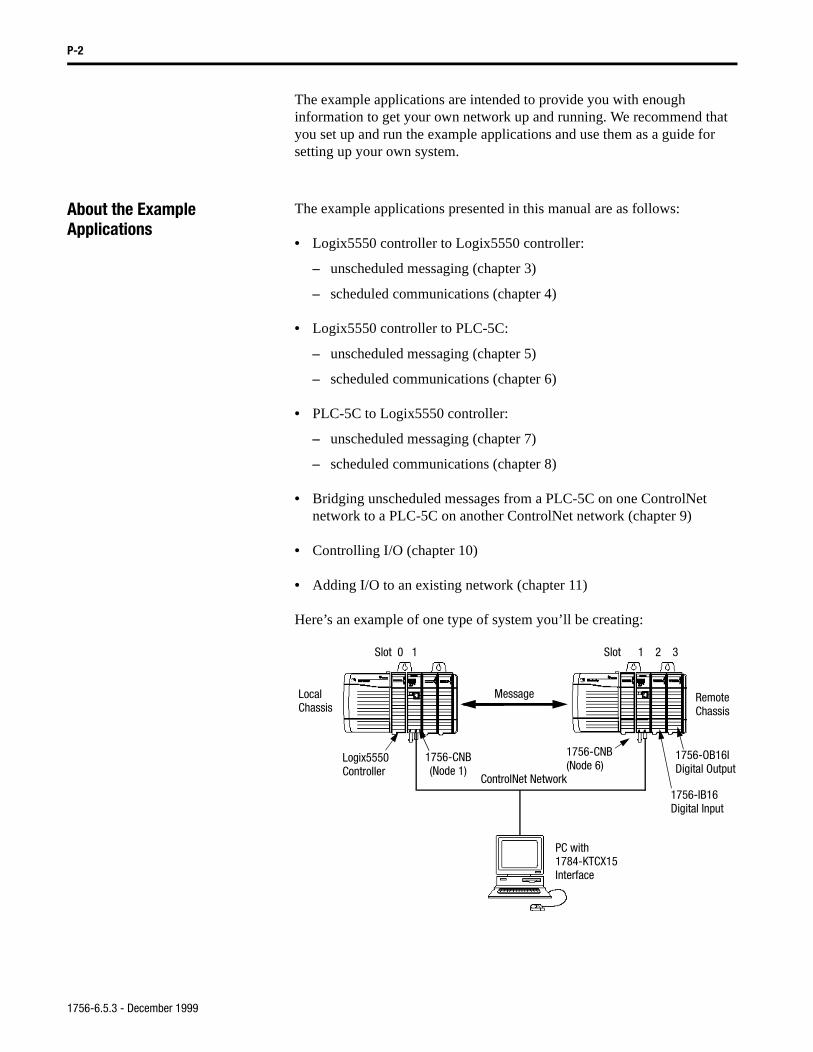
Here’s an example of one type of system you’ll be creating:
ControlNet Network
Logix5550 1756-CNB(Node 1)
1756-CNB(Node 6)
LocalChassis
RemoteChassis
PC with1784-KTCX15Interface
Message
Slot 0 1 Slot 1 2 3
1756-IB16Digital Input
1756-OB16IDigital OutputController
1756-6.5.3 - December 1999
P-3
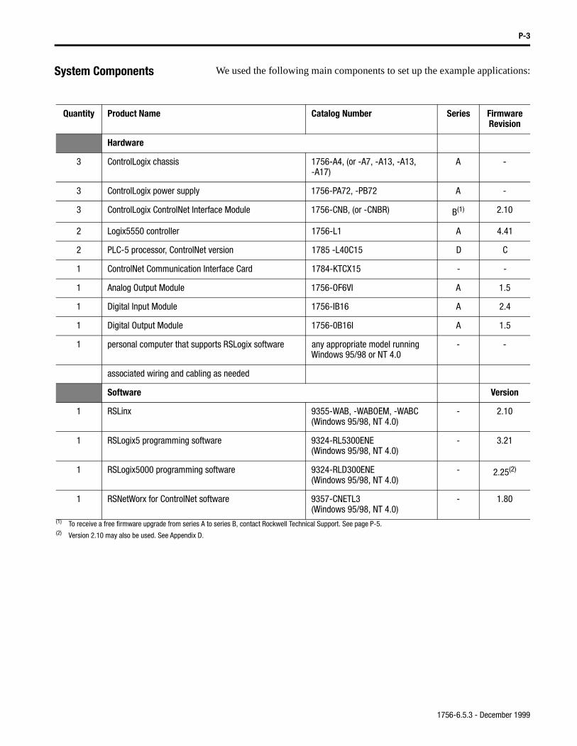
System Components We used the following main components to set up the example applications:
Quantity Product Name Catalog Number Series FirmwareRevision
Hardware
3 ControlLogix chassis 1756-A4, (or -A7, -A13, -A13, -A17)
A -
3 ControlLogix power supply 1756-PA72, -PB72 A -
3 ControlLogix ControlNet Interface Module 1756-CNB, (or -CNBR) B(1) 2.10
2 Logix5550 controller 1756-L1 A 4.41
2 PLC-5 processor, ControlNet version 1785 -L40C15 D C
1 ControlNet Communication Interface Card 1784-KTCX15 - -
1 Analog Output Module 1756-OF6VI A 1.5
1 Digital Input Module 1756-IB16 A 2.4
1 Digital Output Module 1756-0B16I A 1.5
1 personal computer that supports RSLogix software any appropriate model running Windows 95/98 or NT 4.0
- -
associated wiring and cabling as needed
Software Version
1 RSLinx 9355-WAB, -WABOEM, -WABC(Windows 95/98, NT 4.0)
- 2.10
1 RSLogix5 programming software 9324-RL5300ENE(Windows 95/98, NT 4.0)
- 3.21
1 RSLogix5000 programming software 9324-RLD300ENE(Windows 95/98, NT 4.0)
- 2.25(2)
1 RSNetWorx for ControlNet software 9357-CNETL3(Windows 95/98, NT 4.0)
- 1.80
(1) To receive a free firmware upgrade from series A to series B, contact Rockwell Technical Support. See page P-5.(2) Version 2.10 may also be used. See Appendix D.
1756-6.5.3 - December 1999
P-4
Common Techniques Usedin This Manual
The following conventions are used throughout this manual:
• Numbered lists provide sequential steps.
• Bulleted lists provide information, not procedural steps.
• Text in bold font indicates words or phrases you should type, programming windows, and menu selections.
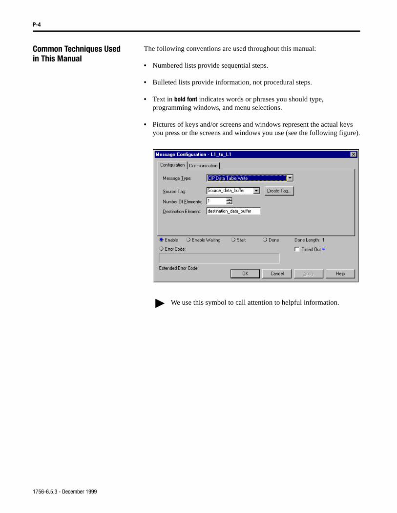
• Pictures of keys and/or screens and windows represent the actual keys you press or the screens and windows you use (see the following figure).
We use this symbol to call attention to helpful information.
1756-6.5.3 - December 1999
P-5
Where to Find More Information
Refer to the following publications as needed for additional help when setting up and using your ControlNet network:
Rockwell Automation Support Rockwell Automation offers support services worldwide, with over 75 sales/support offices, 512 authorized distributors, and 260 authorized systems integrators located throughout the United States alone, plus Rockwell Automation representatives in every major country in the world.
Local Product Support
Contact your local Rockwell Automation representative for:
• sales and order support
• product technical training
• warranty support
• support service agreements
0RUH
For information about See this publication Publication numbernetwork cabling and wiring ControlNet Cable Planning and Installation Guide 1786-6.2.1the ControlLogix ControlNet Interface Module ControlLogix ControlNet Bridge Installation Instructions 1756-5.71the ControlLogix Chassis ControlLogix Chassis Installation instructions 1756-5.2ControlLogix power supplies ControlLogix Power Supplies Installation Instructions 1756-5.1Logix5550 programmable controllers Logix5550 Controller User Manual 1756-6.5.12PLC-5 programmable controllers Enhanced PLC-5 Programmable Controller Quick Start 1785-10.4
ControlNet PLC-5 Programmable Controller Quick Start 1785-10.7 ControlNet PLC-5 Programmable Controller User Manual 1785-6.5.22
ControlLogix Analog I/O modules ControlLogix Analog I/O Users Manual 1756-6.5.9ControlLogix Digital I/O modules ControlLogix Digital I/O Users Manual 1756-6.5.8PC communication interface cards 1784-KTX15 Communication Interface Card User Manual 1784-6.5.22RSLogix5 programming software Getting Results with RSLogix5 9399-RL53GRRSLogix5000 programming software Getting Results with RSLogix5000 9399-RLD300GRRSNetWorx for ControlNet software Getting Results with RSLogix with RSNetWorx for ControlNet 9399-RWCNTGRRSLinx Lite software RSLinx Lite User’s Guide 9399-WAB32LUGcurrent Allen-Bradley documentation, including ordering instructions
Allen-Bradley Publication Index SD499
terms and definitions Allen-Bradley Industrial Automation Glossary AG-7.1
Many of these manuals are available online from the Automation Bookstore, http://www.theautomationbookstore.com.
For more information on Rockwell Software products, visit the Rockwell Software internet site, http://www.software.rockwell.com.
1756-6.5.3 - December 1999
P-6
Technical Product Assistance
If you need to contact Rockwell Automation for technical assistance, call your local Rockwell Automation representative.
Your Questions or Comments about This Manual
If you find a problem with this manual, please notify us of it on the enclosed Publication Problem Report (at the back of this manual).
If you have any suggestions about how we can make this manual more useful to you, please contact us at the following address:
Rockwell Automation, Allen-Bradley Company, Inc. Control and Information GroupTechnical Communication1 Allen-Bradley DriveMayfield Heights, OH 44124-6118
Telephone Number: 1 440 646-6800
1756-6.5.3 - December 1999
Table of Contents
Chapter 1ControlNetCommunication Basics
What This Chapter Contains. . . . . . . . . . . . . . . . . . . . . . . . . . . . . 1-1Module Versions. . . . . . . . . . . . . . . . . . . . . . . . . . . . . . . . . . . . . . 1-1
Before you go any further . . .. . . . . . . . . . . . . . . . . . . . . . . . . 1-1Module Features . . . . . . . . . . . . . . . . . . . . . . . . . . . . . . . . . . . . . . 1-2
Support for up to 64 Bidirectional Connections . . . . . . . . . . . 1-2Bridging Unscheduled Data . . . . . . . . . . . . . . . . . . . . . . . . . . 1-3
Understanding the Producer/Consumer Model . . . . . . . . . . . . . . 1-4Processing Produced and Consumed Tags . . . . . . . . . . . . . . . 1-5Control of Scheduled I/O Communications . . . . . . . . . . . . . . 1-6
Understanding the Control and Information Protocol . . . . . . . . . 1-6Understanding the Network Keeper . . . . . . . . . . . . . . . . . . . . . . . 1-7
Network Update Time (NUT) . . . . . . . . . . . . . . . . . . . . . . . . 1-7Requested Packet Interval (RPI). . . . . . . . . . . . . . . . . . . . . . . 1-7Actual Packet Interval (API) . . . . . . . . . . . . . . . . . . . . . . . . . 1-8Rack Optimized and Direct Connections . . . . . . . . . . . . . . . . 1-8
Default Parameters . . . . . . . . . . . . . . . . . . . . . . . . . . . . . . . . . . . 1-10
Chapter 2Installing theControlNet Network
What this Chapter Contains . . . . . . . . . . . . . . . . . . . . . . . . . . . . . 2-1Installing the 1784-KTCX15 Communication Interface Card . . . 2-2
Configuring the 1784-KTCX15 Card. . . . . . . . . . . . . . . . . . . 2-3Installing the ControlLogix Modules . . . . . . . . . . . . . . . . . . . . . . 2-5Connecting the ControlNet Network . . . . . . . . . . . . . . . . . . . . . . 2-7Installing the PLC-5C Controllers . . . . . . . . . . . . . . . . . . . . . . . . 2-9Required Software . . . . . . . . . . . . . . . . . . . . . . . . . . . . . . . . . . . 2-10
Chapter 3Logix5550 to Logix5550 Controller: Unscheduled Messaging
About the Example Application . . . . . . . . . . . . . . . . . . . . . . . . . . 3-1Set Up the Example Application . . . . . . . . . . . . . . . . . . . . . . . . . 3-1Create the Example Application. . . . . . . . . . . . . . . . . . . . . . . . . . 3-2
Create the Controller Tags for the Write Message Program . 3-3Create the Write Message Ladder Program . . . . . . . . . . . . . . 3-4Download and Run the Program . . . . . . . . . . . . . . . . . . . . . . 3-6
Test the Example Application . . . . . . . . . . . . . . . . . . . . . . . . . . . 3-6Create the Controller Tags for the Test Program . . . . . . . . . . 3-7Download the Test Program . . . . . . . . . . . . . . . . . . . . . . . . . . 3-9Test the Communications . . . . . . . . . . . . . . . . . . . . . . . . . . . 3-10
Chapter 4Logix5550 to Logix5550 Controller: Scheduled Communication
About the Example Application . . . . . . . . . . . . . . . . . . . . . . . . . . 4-1Set Up the Example Application . . . . . . . . . . . . . . . . . . . . . . . . . 4-1Create the Producer Application. . . . . . . . . . . . . . . . . . . . . . . . . . 4-2
Create the Producer Tags . . . . . . . . . . . . . . . . . . . . . . . . . . . . 4-3Create the Producer Ladder Program . . . . . . . . . . . . . . . . . . . 4-5Download to the Producer . . . . . . . . . . . . . . . . . . . . . . . . . . . 4-5
1756-6.5.3 - December 1999
ii
Chapter 4 (continued)Configure the Consumer Logix5550 Controller . . . . . . . . . . . . . . 4-6
Add the Producer to the I/O Configuration of the Consumer . 4-6Create the Consumer Tags . . . . . . . . . . . . . . . . . . . . . . . . . . 4-12Download to the Consumer. . . . . . . . . . . . . . . . . . . . . . . . . . 4-15
Schedule the Network Using RSNetWorx for ControlNet . . . . . 4-16Verify the Network Properties . . . . . . . . . . . . . . . . . . . . . . . 4-17
Test the Communications . . . . . . . . . . . . . . . . . . . . . . . . . . . . . . 4-20
Chapter 5Logix5550 Controller to PLC-5C:Unscheduled Messaging
About the Example Application . . . . . . . . . . . . . . . . . . . . . . . . . . 5-1Set Up the Example Application. . . . . . . . . . . . . . . . . . . . . . . . . . 5-1Create the Example Application . . . . . . . . . . . . . . . . . . . . . . . . . . 5-2
Create the Controller Tags for the Write Message Program. . 5-3Create the Write Message Ladder Program . . . . . . . . . . . . . . 5-4Download the Write Message Program . . . . . . . . . . . . . . . . . 5-6
Test the Example Application. . . . . . . . . . . . . . . . . . . . . . . . . . . . 5-7
Chapter 6Logix5550 Controller to PLC-5C:Scheduled Communications
About the Example Application . . . . . . . . . . . . . . . . . . . . . . . . . . 6-1Set Up the Example Application. . . . . . . . . . . . . . . . . . . . . . . . . . 6-1Create the Logix5550 Producer Application . . . . . . . . . . . . . . . . 6-2
Create the Producer Tags . . . . . . . . . . . . . . . . . . . . . . . . . . . . 6-3Create the Producer Ladder Program . . . . . . . . . . . . . . . . . . . 6-5Download and Run the Program. . . . . . . . . . . . . . . . . . . . . . . 6-6
Schedule the Network Using RSNetWorx for ControlNet . . . . . . 6-7Verify the Network Properties . . . . . . . . . . . . . . . . . . . . . . . . 6-9Survey the Network for Connected Devices. . . . . . . . . . . . . 6-10Configure the PLC-5C to Receive Scheduled Messages . . . 6-11
Test the Communications . . . . . . . . . . . . . . . . . . . . . . . . . . . . . . 6-14
Chapter 7PLC-5C to Logix5550 Controller:Unscheduled Messaging
About the Example Application . . . . . . . . . . . . . . . . . . . . . . . . . . 7-1Set Up the Example Application. . . . . . . . . . . . . . . . . . . . . . . . . . 7-1Create the Example Application . . . . . . . . . . . . . . . . . . . . . . . . . . 7-2
Create the PLC-5C Program . . . . . . . . . . . . . . . . . . . . . . . . . . 7-3Download the PLC-5C Program. . . . . . . . . . . . . . . . . . . . . . . 7-5
Test the Example Application. . . . . . . . . . . . . . . . . . . . . . . . . . . . 7-7Create the Controller Tags for the Logix5550 Controller. . . . 7-8Download the Logix5550 Program. . . . . . . . . . . . . . . . . . . . 7-10Verify the Message . . . . . . . . . . . . . . . . . . . . . . . . . . . . . . . . 7-11
Chapter 8PLC-5C to Logix5550 Controller:Scheduled Communications
About the Example Application . . . . . . . . . . . . . . . . . . . . . . . . . . 8-1Set Up the Example Application. . . . . . . . . . . . . . . . . . . . . . . . . . 8-1Configure the Network Using RSNetWorx for ControlNet . . . . . 8-2
Verify the Network Properties . . . . . . . . . . . . . . . . . . . . . . . . 8-4
1756-6.5.3 - December 1999
iii
Chapter 8 (continued)Survey the Network for Connected Devices . . . . . . . . . . . . . 8-5Configure the PLC-5C Processor . . . . . . . . . . . . . . . . . . . . . . 8-6
Configure the Consumer Logix5550 Controller. . . . . . . . . . . . . . 8-9Add the Producer to the I/O Configuration . . . . . . . . . . . . . 8-10Create the Consumer Tags . . . . . . . . . . . . . . . . . . . . . . . . . . 8-13Download the Logix5550 Program . . . . . . . . . . . . . . . . . . . 8-17
Create the Producer Application. . . . . . . . . . . . . . . . . . . . . . . . . 8-18Create the PLC-5C Program. . . . . . . . . . . . . . . . . . . . . . . . . 8-19Download the PLC-5C Program. . . . . . . . . . . . . . . . . . . . . . 8-19
Schedule the Network. . . . . . . . . . . . . . . . . . . . . . . . . . . . . . . . . 8-22Verify the Message . . . . . . . . . . . . . . . . . . . . . . . . . . . . . . . . . . . 8-23
Chapter 9PLC-5C to PLC-5C Unscheduled Messaging Over Two ControlNet Networks
About the Example Application . . . . . . . . . . . . . . . . . . . . . . . . . . 9-1Set Up the Example Application . . . . . . . . . . . . . . . . . . . . . . . . . 9-1Create the Example Application. . . . . . . . . . . . . . . . . . . . . . . . . . 9-2
Create the Ladder Program. . . . . . . . . . . . . . . . . . . . . . . . . . . 9-3Download the Program. . . . . . . . . . . . . . . . . . . . . . . . . . . . . . 9-5
Test the Example Application . . . . . . . . . . . . . . . . . . . . . . . . . . . 9-6
Chapter 10Controlling I/O Over a ControlNet Network
About the Example Application . . . . . . . . . . . . . . . . . . . . . . . . . 10-1Set Up the Example Application . . . . . . . . . . . . . . . . . . . . . . . . 10-2Create the Example Application. . . . . . . . . . . . . . . . . . . . . . . . . 10-2
Add the Local CNB Module to the I/O Configuration . . . . . 10-3Add the Remote CNB Module to the I/O Configuration . . . 10-4Add the Remote I/O Modules to the I/O Configuration . . . . 10-7Edit the Controller Tags . . . . . . . . . . . . . . . . . . . . . . . . . . . 10-11Create the Ladder Logic Program . . . . . . . . . . . . . . . . . . . 10-12Download the Program. . . . . . . . . . . . . . . . . . . . . . . . . . . . 10-12
Schedule the Network Using RSNetWorx for ControlNet. . . . 10-13Verify the Network Properties . . . . . . . . . . . . . . . . . . . . . . 10-15Survey the Network for Connected Devices . . . . . . . . . . . 10-16Schedule the Network and Save the Configuration . . . . . . 10-17
Test the Example Application . . . . . . . . . . . . . . . . . . . . . . . . . 10-18
Chapter 11Adding an I/O Chassis to an Existing ControlNet Network
About the Example Application . . . . . . . . . . . . . . . . . . . . . . . . . 11-1Set Up the Example Application . . . . . . . . . . . . . . . . . . . . . . . . 11-2Create the Example Application. . . . . . . . . . . . . . . . . . . . . . . . . 11-2
Add the Second Remote 1756-CNB Moduleto the I/O Configuration . . . . . . . . . . . . . . . . . . . . . . . . . . . . 11-3Add the Remote Analog I/O Moduleto the I/O Configuration . . . . . . . . . . . . . . . . . . . . . . . . . . . . 11-5Edit the Controller Tags . . . . . . . . . . . . . . . . . . . . . . . . . . . . 11-9Modify the Ladder Program . . . . . . . . . . . . . . . . . . . . . . . . 11-10
1756-6.5.3 - December 1999
iv
Chapter 11 (continued)Download the Program . . . . . . . . . . . . . . . . . . . . . . . . . . . . 11-10
Schedule the Network Using RSNetWorx for ControlNet . . . . 11-11Verify the Network Properties . . . . . . . . . . . . . . . . . . . . . . 11-13Survey the Network for Connected Devices. . . . . . . . . . . . 11-14Schedule the Network and Save the Configuration . . . . . . 11-15
Test the Example Application. . . . . . . . . . . . . . . . . . . . . . . . . . 11-16Adding 1756-CNB Modules to Expand the Network. . . . . . . . 11-17
Chapter 12Troubleshooting Module Status Indicator and Display . . . . . . . . . . . . . . . . . . 12-1
ControlNet Network Status Indicators . . . . . . . . . . . . . . . . . 12-3
Appendix AAllocating Communication Connections
What This Appendix Contains . . . . . . . . . . . . . . . . . . . . . . . . . . . A-1How the ControlLogix System Uses Connections . . . . . . . . . . . . A-1Determining Connections for I/O Modules . . . . . . . . . . . . . . . . . A-2
Direct connections for I/O modules . . . . . . . . . . . . . . . . . . . . A-2Rack optimized connections for I/O modules. . . . . . . . . . . . . A-3Combining direct and rack optimized connections. . . . . . . . . A-5
Determining Connections for Produced and Consumed Tags . . . A-6Connections for produced tags . . . . . . . . . . . . . . . . . . . . . . . . A-6Optimizing produced tags . . . . . . . . . . . . . . . . . . . . . . . . . . . . A-7Connections for consumed tags . . . . . . . . . . . . . . . . . . . . . . . A-7
Determining Connections for Messaging . . . . . . . . . . . . . . . . . . . A-8Determining Total Connection Requirements . . . . . . . . . . . . . . . A-9
Appendix BCreating Produced and Consumed Tags
What This Appendix Contains . . . . . . . . . . . . . . . . . . . . . . . . . . . B-1Produced Tags. . . . . . . . . . . . . . . . . . . . . . . . . . . . . . . . . . . . . . . . B-1Consumed Tags. . . . . . . . . . . . . . . . . . . . . . . . . . . . . . . . . . . . . . . B-3Producing a tag from a Logix5550 Controllerto a ControlNet PLC-5 Processor . . . . . . . . . . . . . . . . . . . . . . . . . B-5Consuming a tag from a ControlNet PLC-5 Processorto a Logix5550 Controller. . . . . . . . . . . . . . . . . . . . . . . . . . . . . . . B-5
Appendix CElectronic Keying Specifying Electronic Keying . . . . . . . . . . . . . . . . . . . . . . . . . . . . C-1
Appendix DSetting Paths for Downloads in RSLogix5000, Version 2.10
Communications Path . . . . . . . . . . . . . . . . . . . . . . . . . . . . . . . . . . D-1
Index
1756-6.5.3 - December 1999
Chapter 1
ControlNet Communication Basics
What This Chapter Contains This chapter provides an overview of the primary features and requirements of ControlNet communication using the 1756-CNB module.
Module Versions The ControlLogix ControlNet interface module is available in redundant (1756-CNBR) and non-redundant (1756-CNB) configurations. Either version may be used in the example applications, but for simplicity, we refer to both as the 1756-CNB module.
Before you go any further . . .
The example applications use series B (firmware version 2.10) 1756-CNB modules. If you currently have series A modules, you can obtain free firmware upgrades to series B by contacting Rockwell Technical Support. See page P-6.
For information about See page
Module Versions 1-1
Support for up to 64 Bidirectional Connections 1-2
Bridging Unscheduled Data 1-3
Understanding the Producer/Consumer Model 1-4
Processing Produced and Consumed Tags 1-5
Control of Scheduled I/O Communications 1-6
Understanding the Control and Information Protocol 1-6
Understanding the Network Keeper 1-7
Network Update Time (NUT) 1-7
Requested Packet Interval (RPI) 1-7
Actual Packet Interval (API) 1-8
Rack Optimized and Direct Connections 1-8
Default Parameters 1-10
For further information on the differences between using the redundant and non-redundant versions of the 1756-CNB module in your network, refer to the ControlNet Cable Planning and Installation Manual, publication 1786-6.2.1.
1756-6.5.3 - December 1999
1-2 ControlNet Communication Basics
Module Features The 1756-CNB module performs two primary tasks:
1. control of I/O data in conjunction with a Logix5550 controller (scheduled data)
2. support of messaging data for configuration and programming information (unscheduled data)
The 1756-CNB module has these primary features:
• support for a maximum of 64 bidirectional connections with other ControlNet devices
• support of up to 20 buffers for unconnected messages
• bridging of unscheduled data (messaging and programming information)
• control of scheduled I/O and scheduled data (in conjunction with a Logix5550 controller)
Support for up to 64 Bidirectional Connections
A connection is an open communication path between the data producer and the data consumer on the network. The connection includes information about the location of the consumer that significantly decreases the data overhead. By contrast, an unconnected message is a traditional message that uses the network address of the target device and the data address within the target.
The 1756-CNB module supports a maximum of 64 bidirectional connections. These connections can be any mix of unscheduled and scheduled connections. If your application requires more connections, you can place additional 1756-CNB modules in the same chassis and on the same network as the first module to provide additional connections.
Important: The number of connections that can actually be supported on a network is dependent upon the network configuration. For example, only 10 to 12 connections can be supported at an RPI (requested packet interval) of 5ms, and only 4 at an RPI of 2ms.
Important: If you choose to use additional modules to provide additional connections, be sure to partition your application so that it best uses the additional modules. See page 11-17 for an example network.
1756-6.5.3 - December 1999
ControlNet Communication Basics 1-3
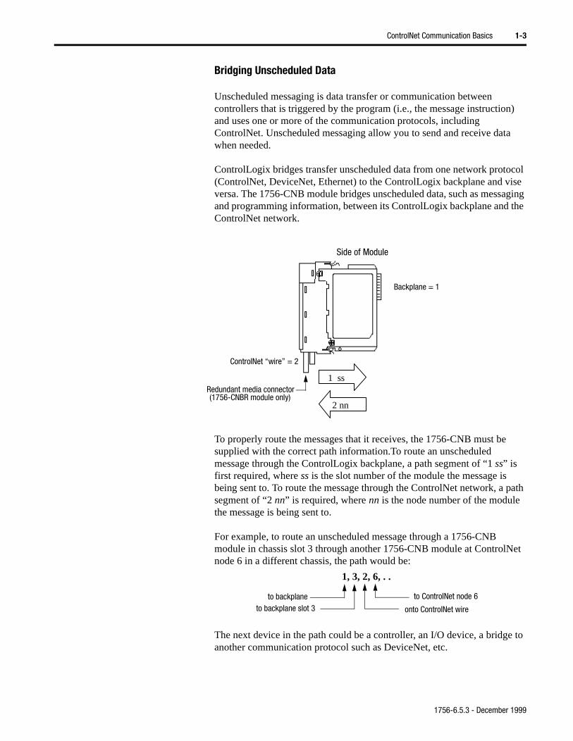
path
et
e to
Bridging Unscheduled Data
Unscheduled messaging is data transfer or communication between controllers that is triggered by the program (i.e., the message instruction) and uses one or more of the communication protocols, including ControlNet. Unscheduled messaging allow you to send and receive data when needed.
ControlLogix bridges transfer unscheduled data from one network protocol (ControlNet, DeviceNet, Ethernet) to the ControlLogix backplane and vise versa. The 1756-CNB module bridges unscheduled data, such as messaging and programming information, between its ControlLogix backplane and the ControlNet network.
To properly route the messages that it receives, the 1756-CNB must be supplied with the correct path information.To route an unscheduled message through the ControlLogix backplane, a path segment of “1 ss” is first required, where ss is the slot number of the module the message is being sent to. To route the message through the ControlNet network, a segment of “2 nn” is required, where nn is the node number of the module the message is being sent to.
For example, to route an unscheduled message through a 1756-CNB module in chassis slot 3 through another 1756-CNB module at ControlNnode 6 in a different chassis, the path would be:
The next device in the path could be a controller, an I/O device, a bridganother communication protocol such as DeviceNet, etc.
2 nn
1 ss
Side of Module
Backplane = 1
ControlNet “wire” = 2
Redundant media connector(1756-CNBR module only)
to backplaneto backplane slot 3 onto ControlNet wire
to ControlNet node 6
1, 3, 2, 6, . .
1756-6.5.3 - December 1999
1-4 ControlNet Communication Basics
ata
e
The the
d
With the RSLogix5000 programming software the path is configured using the Communication tab in the Message Configuration window. See page 3-5 for an example.
Understanding the Producer/Consumer Model
In traditional I/O systems, controllers poll input modules to obtain their input status. Digital input modules in the ControlLogix system are not polled by a controller. Instead, the modules produce (“multicast”) their deither upon a change of state or periodically. The frequency of update depends upon the options chosen during configuration and where on thnetwork the input module resides. The input module, therefore, is a producer of input data and the controller is a consumer of the data.
The controller can also produce data for other controllers to consume. produced and consumed data is accessible by multiple controllers overControlBus backplane and over the ControlNet network. This data exchange conforms to the producer/consumer model.
This manual provides examples of the producer/consumer model as it applies to ControlLogix and PLC-5C controllers.
Note that PLC-5 terminology differs slightly from that used by ControlLogix. A PLC-5C “send scheduled message” is functionally equivalent to a ControlLogix “produced tag.” A PLC5 “receive schedulemessage” is functionally equivalent to a ControlLogix “consumed tag.”
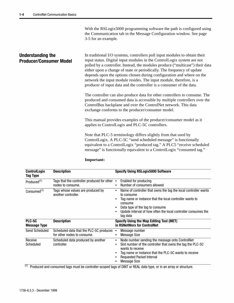
Important:
ControlLogixTag Type
Description Specify Using RSLogix5000 Software
Produced(1) Tags that the controller produced for other nodes to consume.
• Enabled for producing• Number of consumers allowed
Consumed(1) Tags whose values are produced by another controller.
• Name of controller that owns the tag the local controller wants to consume
• Tag name or instance that the local controller wants to consume
• Data type of the tag to consume• Update interval of how often the local controller consumes the
tag dataPLC-5CMessage Type
Description Specify Using the Map Editing Tool (MET)in RSNetWorx for ControlNet
Send Scheduled Scheduled data that the PLC-5C produces for other nodes to consume.
• Message number• Message Size
Receive Scheduled
Scheduled data produced by another controller.
• Node number sending the message onto ControlNet• Slot number of the controller that owns the tag the PLC-5C
wants to receive• Tag name or instance that the PLC-5C wants to receive• Requested Packet Interval• Message Size
(1) Produced and consumed tags must be controller-scoped tags of DINT or REAL data type, or in an array or structure.
1756-6.5.3 - December 1999
ControlNet Communication Basics 1-5
See the chapters on scheduled communications for examples of creating produced/consumed tags and send/receive scheduled messages.
Processing Produced and Consumed Tags
In the producer/consumer model, the consumer is the connection originator (it opens the connection). When several consumers are trying to open the connection to the same tag, the connection will be opened to transfer data at the rate of the consumer with the smallest API (see Actual Packet Interval on page 1-8).
The producer and consumer must be configured correctly for the specified data to be shared. To produce for several consumers, the producer must be configured for this using the RSLogix5000 software for the Logix5550 controller. For the PLC-5C send and receive scheduled messages are configured using the Map Editing Tool in RSNetWorx for ControlNet.
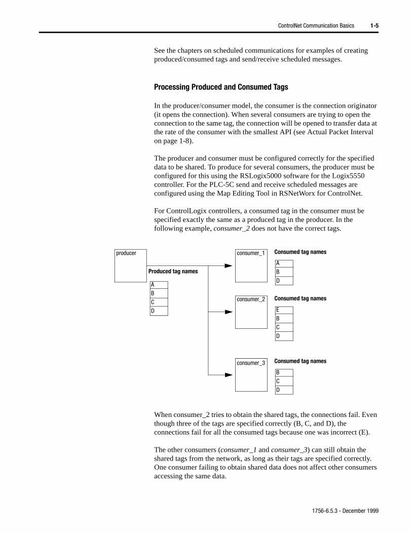
For ControlLogix controllers, a consumed tag in the consumer must be specified exactly the same as a produced tag in the producer. In the following example, consumer_2 does not have the correct tags.
When consumer_2 tries to obtain the shared tags, the connections fail. Even though three of the tags are specified correctly (B, C, and D), the connections fail for all the consumed tags because one was incorrect (E).
The other consumers (consumer_1 and consumer_3) can still obtain the shared tags from the network, as long as their tags are specified correctly. One consumer failing to obtain shared data does not affect other consumers accessing the same data.
A
B
C
D
Produced tag names
producer consumer_1
consumer_2
consumer_3
E
B
C
D
Consumed tag names
B
C
D
Consumed tag names
A
B
D
Consumed tag names
1756-6.5.3 - December 1999
1-6 ControlNet Communication Basics
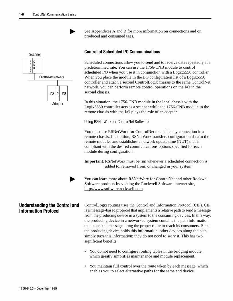
Control of Scheduled I/O Communications
Scheduled connections allow you to send and to receive data repeatedly at a predetermined rate. You can use the 1756-CNB module to control scheduled I/O when you use it in conjunction with a Logix5550 controller. When you place the module in the I/O configuration list of a Logix5550 controller and attach a second ControlLogix chassis to the same ControlNet network, you can perform remote control operations on the I/O in the second chassis.
In this situation, the 1756-CNB module in the local chassis with the Logix5550 controller acts as a scanner while the 1756-CNB module in the remote chassis with the I/O plays the role of an adapter.
Using RSNetWorx for ControlNet Software
You must use RSNetWorx for ControlNet to enable any connection in a remote chassis. In addition, RSNetWorx transfers configuration data to the remote modules and establishes a network update time (NUT) that is compliant with the desired communications options specified for each module during configuration.
Important: RSNetWorx must be run whenever a scheduled connection is added to, removed from, or changed in your system.
Understanding the Control and Information Protocol
ControlLogix routing uses the Control and Information Protocol (CIP). CIP is a message-based protocol that implements a relative path to send a message from the producing device in a system to the consuming devices. In this way, the producing device in a networked system contains the path information that steers the message along the proper route to reach its consumers. Since the producing device holds this information, other devices along the path simply pass this information; they do not need to store it. This has two significant benefits:
• You do not need to configure routing tables in the bridging module, which greatly simplifies maintenance and module replacement.
• You maintain full control over the route taken by each message, which enables you to select alternative paths for the same end device.
See Appendices A and B for more information on connections and on produced and consumed tags.
I/O I/O
CNB
L5550
CNB
Scanner
Adaptor
ControlNet Network
You can learn more about RSNetWorx for ControlNet and other Rockwell Software products by visiting the Rockwell Software internet site, http://www.software.rockwell.com.
1756-6.5.3 - December 1999
ControlNet Communication Basics 1-7
it
On egal
.
ake
ons
test
ata
r, to the
I)
CNB ber
Understanding the Network Keeper
Every ControlNet network requires at least one module that is able to store programmed parameters for the network and configure the network with those parameters upon start-up. This module is called a “keeper” sincekeeps the network configuration. The keeper is configured by running RSNetWorx for ControlNet software.
Series B 1756-CNB modules (firmware version 2.10) are multi-keepers.a multi-keeper network, any CNB module can keep the network at any lnode address (01 to 99). In a multi-keeper network, the multi-keeper capable node with the lowest node address becomes the active keeper
If the active keeper is taken off the network, an alternative keeper can tover for it and continue to act as keeper. As long as at least one valid multi-keeper device is present on the network, new scheduled connectican be established.
Network Update Time (NUT)
The network update time (NUT) is the smallest repetitive time interval inwhich data can be sent on the ControlNet network. It represents the faspossible update rate for scheduled data transfers on that network. For example, a network that runs with a 5ms NUT cannot send scheduled dat a rate faster than 5ms. It can, however, send data at a slower rate.
Requested Packet Interval (RPI)
The RPI is the update rate specified for a particular piece of data on thenetwork. When you add a module to the I/O configuration of a controlleyou must enter the RPI as a parameter. This value specifies how often produce the data for that module. For example, if you specify an RPI of50ms, it means that every 50ms the I/O module should send its data tocontroller or that the controller should send its data to the I/O module.
When you run RSNetWorx for ControlNet an Actual Packet Interval (APwill be calculated. The API will be equal to or faster than the RPI.
RPIs are only used for modules that produce data. For example a local module does not require an RPI because it is not a data-producing memof the system; it is used only as a bridge to remote racks.
Important: You cannot set the RPI to a rate faster than the NUT. The network cannot send data at a rate that is faster than NUT.
1756-6.5.3 - December 1999
1-8 ControlNet Communication Basics
es end
rk I of
ler ces.
I/O
eded ng
Actual Packet Interval (API)
The API is the actual update rate for a particular piece of data on the network. ControlNet will set this rate equal to or faster than the RPI, based upon the binary multiple of the NUT which is the next fastest rate at which a module can send data. If this can not be done, ControlNet will provide feedback that the configuration can not be supported.
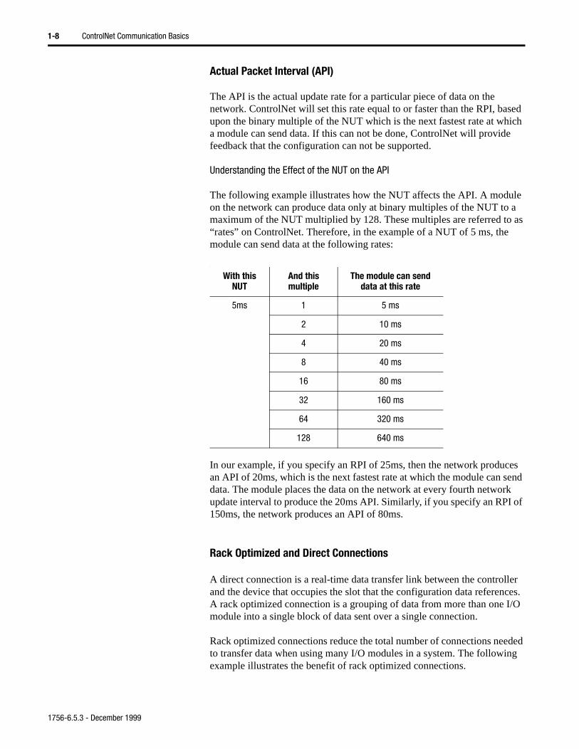
Understanding the Effect of the NUT on the API
The following example illustrates how the NUT affects the API. A module on the network can produce data only at binary multiples of the NUT to a maximum of the NUT multiplied by 128. These multiples are referred to as “rates” on ControlNet. Therefore, in the example of a NUT of 5 ms, themodule can send data at the following rates:
:
In our example, if you specify an RPI of 25ms, then the network producan API of 20ms, which is the next fastest rate at which the module can sdata. The module places the data on the network at every fourth netwoupdate interval to produce the 20ms API. Similarly, if you specify an RP150ms, the network produces an API of 80ms.
Rack Optimized and Direct Connections
A direct connection is a real-time data transfer link between the controland the device that occupies the slot that the configuration data referenA rack optimized connection is a grouping of data from more than one module into a single block of data sent over a single connection.
Rack optimized connections reduce the total number of connections neto transfer data when using many I/O modules in a system. The followiexample illustrates the benefit of rack optimized connections.
With this NUT
And this multiple
The module can send data at this rate
5ms 1 5 ms
2 10 ms
4 20 ms
8 40 ms
16 80 ms
32 160 ms
64 320 ms
128 640 ms
1756-6.5.3 - December 1999
ControlNet Communication Basics 1-9
ction 64 rces.
o
Assume you have set up a system that contains 10 discrete I/O modules in a remote ControlNet chassis. If you used direct connections to transfer data to each of the these I/O modules, you would need 11 connections to transfer all of the data (one connection to the communication module and 1 connection to each of the ten I/O modules). If you used a rack-optimized connection to transfer the data, you would only need a single connection – the conneto the communication module. Since the 1756-CNB module is limited toconnections, using rack-optimized connections can save valuable resou
Important: Although rack optimized connections offer an efficient way tuse resources, there are a few limitations on their use:
• You can only use rack optimized connections to send data to and from discrete digital I/O modules. Analog I/O requires direct connections.
• Rack optimized connections can contain I/O data and status information only. Additional module information, such as diagnostics, is not available through a rack-optimized connection.
• You must use a consistent RPI for all data in a single rack-optimized connection. Since you are using a single connection to send the data, all of the data will be transferred in the same message at a uniform rate.
Mixing Communication Formats
When multiple I/O modules exist in the same chassis, the user can mix Comm Formats for the different I/O modules. I/O modules set up to use Rack Optimization will communicate at the rate of the RPI configured for the 1756-CNB module. I/O modules configured for direct communication will communicate at their set RPI and ignore the CNB RPI.
Important: After the proper I/O configuration is set up in RSLogix5000, I/O communication on ControlNet is not established until RSNetWorx for ControlNet software is run. RSNetWorx is used to set up the network parameters of a ControlNet network.
See Appendix A for more information on connections.
1756-6.5.3 - December 1999
1-10 ControlNet Communication Basics
Default Parameters When a ControlNet network is powered on for the first time, it comes up with a default set of ControlNet parameters capable of sending only unscheduled data. The default set of network parameters in the 1756-CNB, as well as all ControlNet devices, is:
• Network Update Time (NUT) of 100ms
• Scheduled Maximum Node Address (SMAX) of 0
The SMAX is the highest network address of a node that can use the scheduled service.
• Unscheduled Maximum Node Address (UMAX) of 99
The UMAX is the highest network address of a node that can communicate on the ControlNet network. The UMAX must be set equal to or higher than the SMAX.
• Assumed maximum cable lengths and maximum number of repeaters
With this default ControlNet network, you can communicate between the various devices on the network by using such packages as RSNetWorx for ControlNet, RSLogix5000, and the ControlLogix Gateway Tool (1756-GTWY).
If used in this default state, optimum performance may not be achieved. However, the default network can be commissioned (tuned) for optimum performance, as described later in this manual.
Important: The ControlNet network should be configured using RSNetWorx for ControlNet to improve performance.
At a minimum, we recommend that the Unscheduled Maximum Node Address (UMAX) be set equal to the highest node address on the network. Leaving this parameter at the default value of 99 will waste bandwidth and reduce system performance.
We also recommend setting the Scheduled Maximum Node Address (SMAX) to a value 3 or 4 above the highest scheduled node address to allow for future expandability.
1756-6.5.3 - December 1999
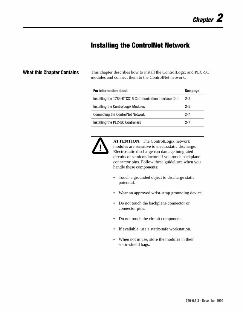
Chapter 2
Installing the ControlNet Network
What this Chapter Contains This chapter describes how to install the ControlLogix and PLC-5C modules and connect them to the ControlNet network.
For information about See page
Installing the 1784-KTCX15 Communication Interface Card 2-2
Installing the ControlLogix Modules 2-5
Connecting the ControlNet Network 2-7
Installing the PLC-5C Controllers 2-7
!ATTENTION: The ControlLogix network modules are sensitive to electrostatic discharge. Electrostatic discharge can damage integrated circuits or semiconductors if you touch backplane connector pins. Follow these guidelines when you handle these components:
• Touch a grounded object to discharge static potential.
• Wear an approved wrist-strap grounding device.
• Do not touch the backplane connector or connector pins.
• Do not touch the circuit components.
• If available, use a static-safe workstation.
• When not in use, store the modules in their static-shield bags.
1756-6.5.3 - December 1999
2-2 Installing the ControlNet Network
.
h
e ings
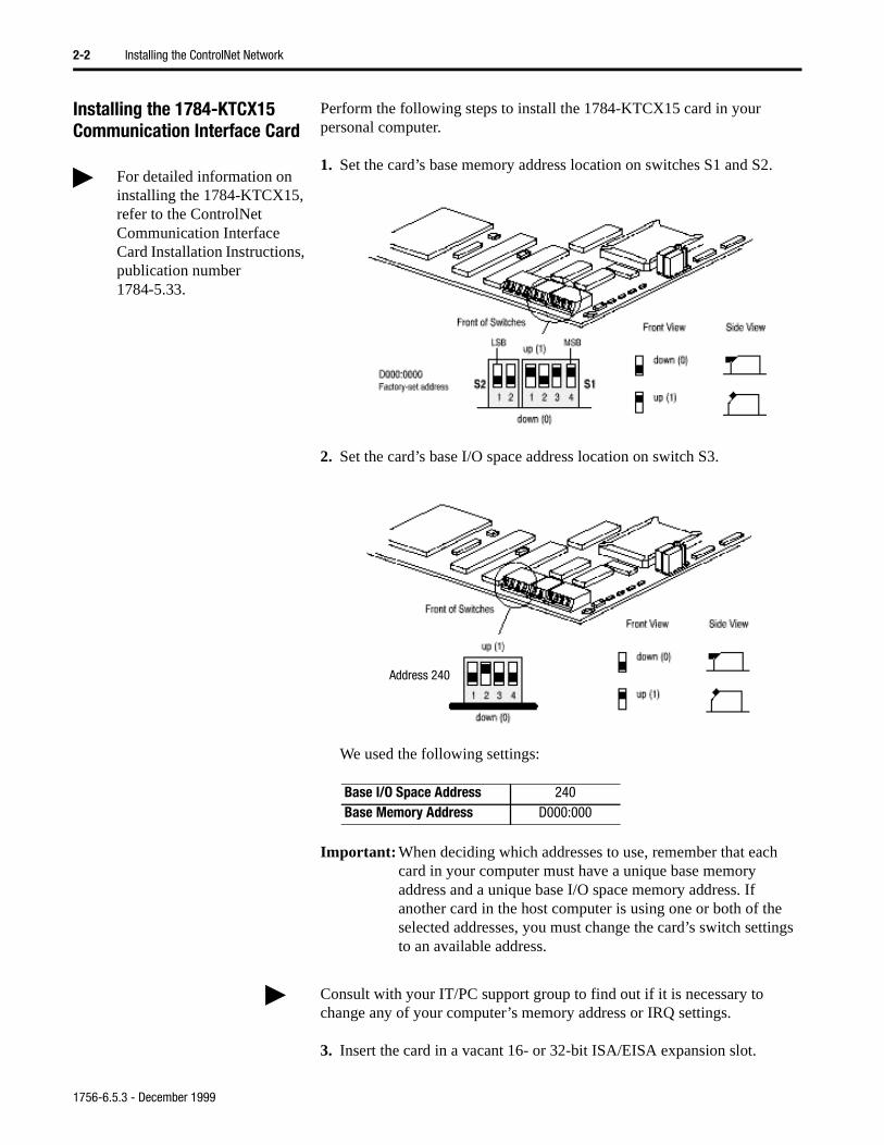
Installing the 1784-KTCX15 Communication Interface Card
Perform the following steps to install the 1784-KTCX15 card in your personal computer.
1. Set the card’s base memory address location on switches S1 and S2
2. Set the card’s base I/O space address location on switch S3.
We used the following settings:
Important: When deciding which addresses to use, remember that eaccard in your computer must have a unique base memory address and a unique base I/O space memory address. If another card in the host computer is using one or both of thselected addresses, you must change the card’s switch settto an available address.
3. Insert the card in a vacant 16- or 32-bit ISA/EISA expansion slot.
For detailed information on installing the 1784-KTCX15, refer to the ControlNet Communication Interface Card Installation Instructions, publication number 1784-5.33.
Base I/O Space Address 240Base Memory Address D000:000
Address 240
Consult with your IT/PC support group to find out if it is necessary to change any of your computer’s memory address or IRQ settings.
1756-6.5.3 - December 1999
Installing the ControlNet Network 2-3
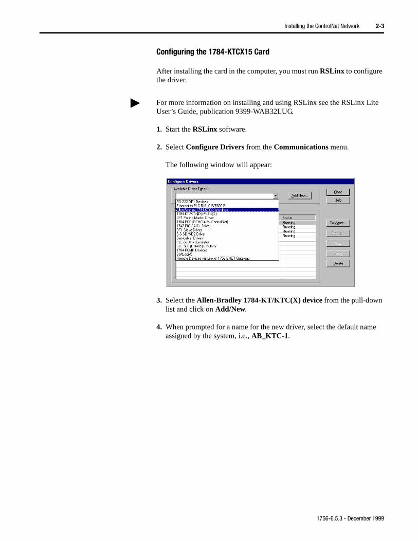
Configuring the 1784-KTCX15 Card
After installing the card in the computer, you must run RSLinx to configure the driver.
1. Start the RSLinx software.
2. Select Configure Drivers from the Communications menu.
The following window will appear:
3. Select the Allen-Bradley 1784-KT/KTC(X) device from the pull-down list and click on Add/New.
4. When prompted for a name for the new driver, select the default name assigned by the system, i.e., AB_KTC-1.
For more information on installing and using RSLinx see the RSLinx Lite User’s Guide, publication 9399-WAB32LUG.
1756-6.5.3 - December 1999
2-4 Installing the ControlNet Network
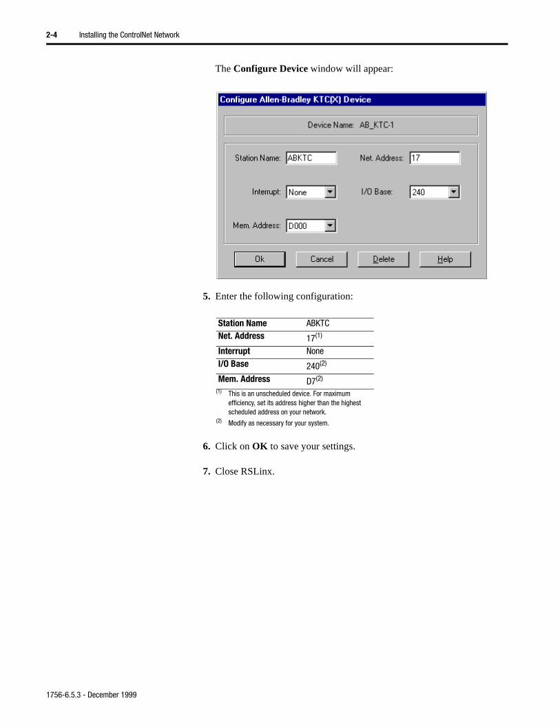
The Configure Device window will appear:
5. Enter the following configuration:
6. Click on OK to save your settings.
7. Close RSLinx.
Station Name ABKTCNet. Address 17(1)
(1) This is an unscheduled device. For maximum efficiency, set its address higher than the highest scheduled address on your network.
Interrupt NoneI/O Base 240(2)
(2) Modify as necessary for your system.
Mem. Address D7(2)
1756-6.5.3 - December 1999
Installing the ControlNet Network 2-5
B ded
Installing the ControlLogix Modules
Important: These instructions assume that you have installed your ControlLogix chassis and power supplies. If you have not installed these components, install them now in accordance with the following instructions:
• ControlLogix Chassis Installation Instructions, publication number 1756-5.2
• ControlLogix Power Supplies Installation Instructions, publication number 1756-5.1
1. Before installing a 1756-CNB module in its chassis, set the module’snode address switches.
Important: You must select a unique node address of 01 to 99 for eachmodule. 00 is invalid.
For the example applications, set the node address of one 1756-CNmodule to 1 and another to 6. In the last example (chapter 11), we ada third module at node address 3.
20926
top of CNB module
front
of m
odul
e
side of CNB module
This module’s network address is 23.
front
1756-6.5.3 - December 1999
2-6 Installing the ControlNet Network
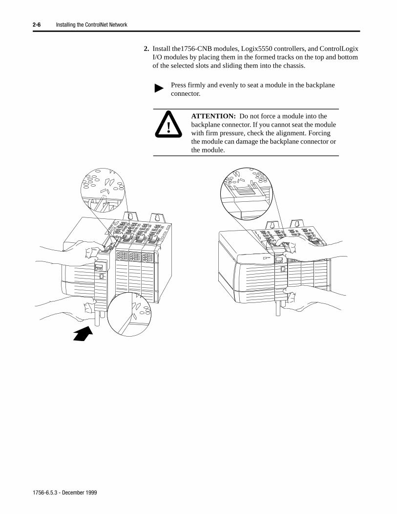
2. Install the1756-CNB modules, Logix5550 controllers, and ControlLogix I/O modules by placing them in the formed tracks on the top and bottom of the selected slots and sliding them into the chassis.
Press firmly and evenly to seat a module in the backplane connector.
!ATTENTION: Do not force a module into the backplane connector. If you cannot seat the module with firm pressure, check the alignment. Forcing the module can damage the backplane connector or the module.
1756-6.5.3 - December 1999
Installing the ControlNet Network 2-7
Important: You can install or remove a module while chassis power is applied.
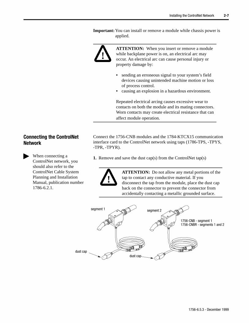
Connecting the ControlNet Network
Connect the 1756-CNB modules and the 1784-KTCX15 communication interface card to the ControlNet network using taps (1786-TPS, -TPYS, -TPR, -TPYR).
1. Remove and save the dust cap(s) from the ControlNet tap(s)
.
!ATTENTION: When you insert or remove a module while backplane power is on, an electrical arc may occur. An electrical arc can cause personal injury or property damage by:
• sending an erroneous signal to your system’s field devices causing unintended machine motion or loss of process control.
• causing an explosion in a hazardous environment.
Repeated electrical arcing causes excessive wear to contacts on both the module and its mating connectors. Worn contacts may create electrical resistance that can affect module operation.
When connecting a ControlNet network, you should also refer to the ControlNet Cable System Planning and Installation Manual, publication number 1786-6.2.1.
!ATTENTION: Do not allow any metal portions of the tap to contact any conductive material. If you disconnect the tap from the module, place the dust cap back on the connector to prevent the connector from accidentally contacting a metallic grounded surface.
segment 1 segment 2
dust capdust cap
1756-CNB - segment 11756-CNBR - segments 1 and 2
1756-6.5.3 - December 1999
2-8 Installing the ControlNet Network
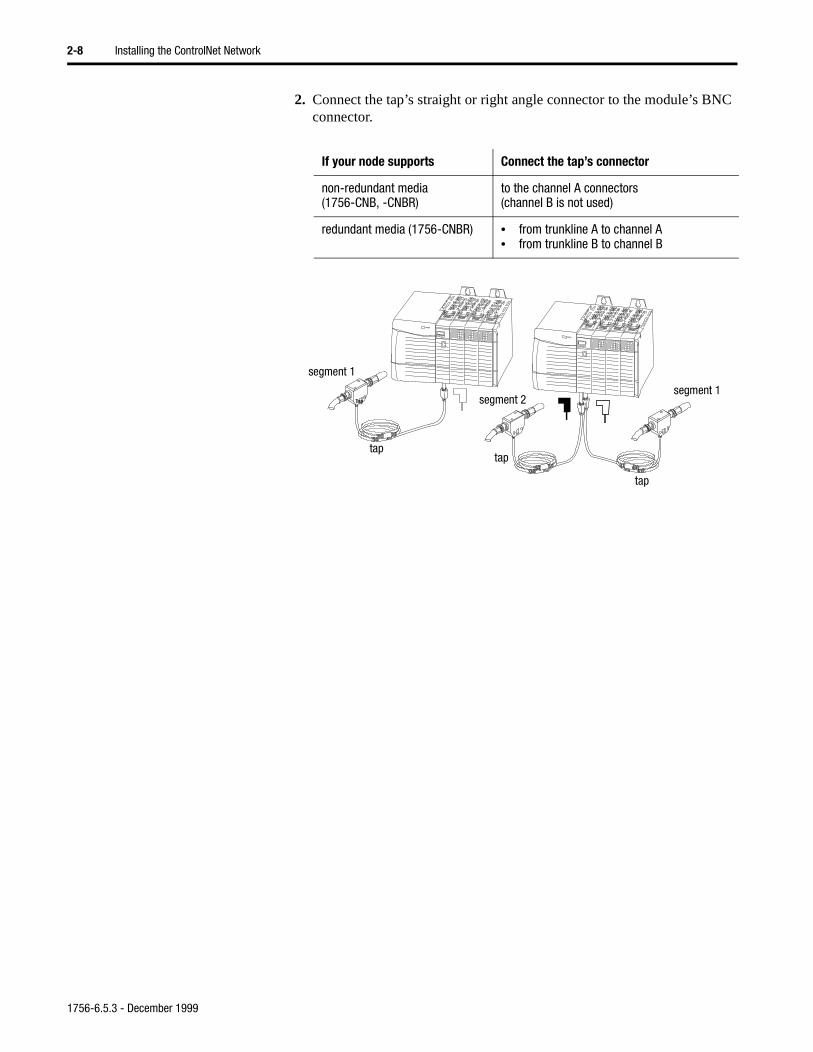
NC
2. Connect the tap’s straight or right angle connector to the module’s Bconnector..
If your node supports Connect the tap’s connector
non-redundant media (1756-CNB, -CNBR)
to the channel A connectors(channel B is not used)
redundant media (1756-CNBR) • from trunkline A to channel A• from trunkline B to channel B
Tap segment 2
taptap
tap
segment 1
segment 1
20956
1756-6.5.3 - December 1999
Installing the ControlNet Network 2-9
tary
Installing the PLC-5C Controllers
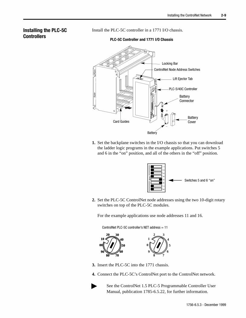
Install the PLC-5C controller in a 1771 I/O chassis.
1. Set the backplane switches in the I/O chassis so that you can download the ladder logic programs in the example applications. Put switches 5 and 6 in the “on” position, and all of the others in the “off” position.
2. Set the PLC-5C ControlNet node addresses using the two 10-digit roswitches on top of the PLC-5C modules.
For the example applications use node addresses 11 and 16.
3. Insert the PLC-5C into the 1771 chassis.
4. Connect the PLC-5C’s ControlNet port to the ControlNet network.
See the ControlNet 1.5 PLC-5 Programmable Controller User Manual, publication 1785-6.5.22, for further information.
Card Guides
Battery
Battery
Battery
PLC-5/40C Controller
Lift Ejector Tab
Locking Bar
Connector
Cover
ControlNet Node Address Switches
PLC-5C Controller and 1771 I/O Chassis
12
34
56
78
OPEN
Switches 5 and 6 “on”
ControlNet PLC-5C controller’s NET address = 11
3040
50
607080
90
00
1020 3
4
5
6 7 8
9
0
1 230
40
50
607080
90
00
1020
1756-6.5.3 - December 1999
2-10 Installing the ControlNet Network
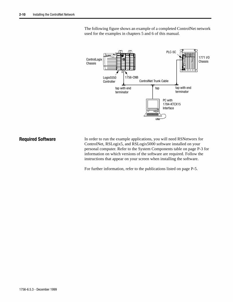
The following figure shows an example of a completed ControlNet network used for the examples in chapters 5 and 6 of this manual.
Required Software In order to run the example applications, you will need RSNetworx for ControlNet, RSLogix5, and RSLogix5000 software installed on your personal computer. Refer to the System Components table on page P-3 for information on which versions of the software are required. Follow the instructions that appear on your screen when installing the software.
For further information, refer to the publications listed on page P-5.
ControlNet Trunk CableLogix5550 1756-CNB
PLC-5C
ControlLogixChassis
1771 I/OChassis
PC with1784-KTCX15Interface
Controller
tap tap with endterminator
tap with endterminator
1756-6.5.3 - December 1999
Chapter 3
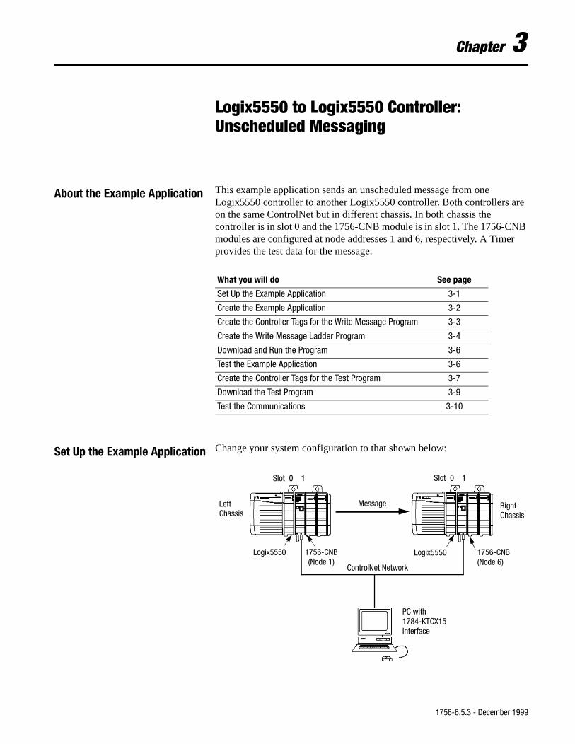
Logix5550 to Logix5550 Controller: Unscheduled Messaging
About the Example Application This example application sends an unscheduled message from one Logix5550 controller to another Logix5550 controller. Both controllers are on the same ControlNet but in different chassis. In both chassis the controller is in slot 0 and the 1756-CNB module is in slot 1. The 1756-CNB modules are configured at node addresses 1 and 6, respectively. A Timer provides the test data for the message.
Set Up the Example Application Change your system configuration to that shown below:
What you will do See page
Set Up the Example Application 3-1
Create the Example Application 3-2
Create the Controller Tags for the Write Message Program 3-3
Create the Write Message Ladder Program 3-4
Download and Run the Program 3-6
Test the Example Application 3-6
Create the Controller Tags for the Test Program 3-7
Download the Test Program 3-9
Test the Communications 3-10
ControlNet Network
Logix5550 1756-CNB(Node 1)
1756-CNB(Node 6)
Logix5550
LeftChassis
RightChassis
PC with1784-KTCX15Interface
Message
Slot 0 1 Slot 0 1
1756-6.5.3 - December 1999
3-2 Logix5550 to Logix5550 Controller: Unscheduled Messaging
g.”
• Verify that the Logix5550 controllers and the 1756-CNB modules are in slots 0 and 1 in each ControlLogix chassis, as shown.
• Verify that the node addresses for the 1756-CNB modules are 1 and 6 as shown.
• Verify that the KTCX15 driver card is configured as described on page 2-3.
• Verify that all wiring and cabling is properly connected.
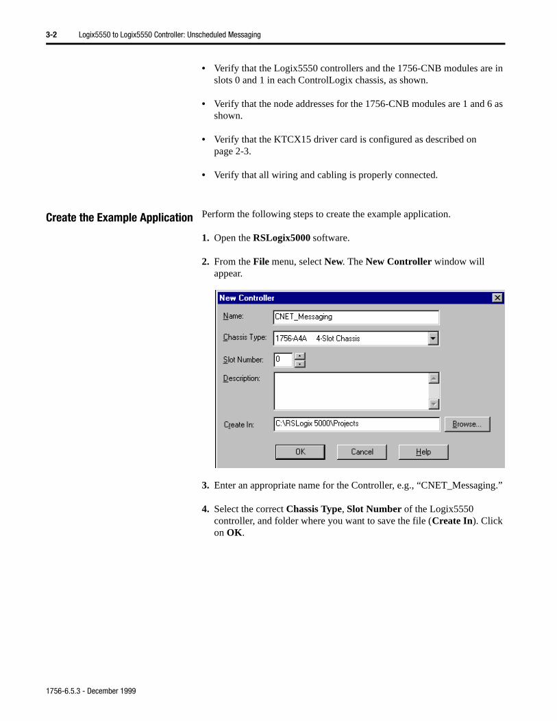
Create the Example Application Perform the following steps to create the example application.
1. Open the RSLogix5000 software.
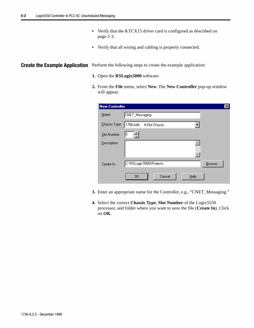
2. From the File menu, select New. The New Controller window will appear.
3. Enter an appropriate name for the Controller, e.g., “CNET_Messagin
4. Select the correct Chassis Type, Slot Number of the Logix5550 controller, and folder where you want to save the file (Create In). Click on OK.
1756-6.5.3 - December 1999
Logix5550 to Logix5550 Controller: Unscheduled Messaging 3-3
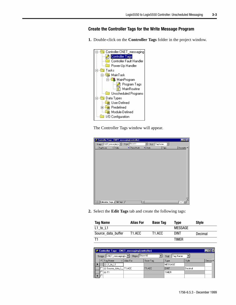
Create the Controller Tags for the Write Message Program
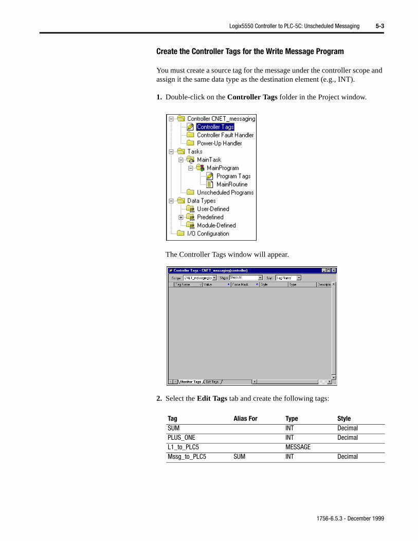
1. Double-click on the Controller Tags folder in the project window.
The Controller Tags window will appear.
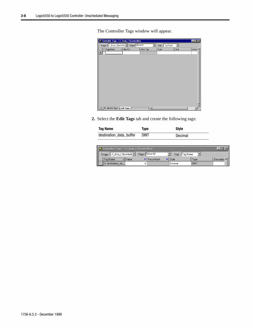
2. Select the Edit Tags tab and create the following tags:
Tag Name Alias For Base Tag Type StyleL1_to_L1 MESSAGESource_data_buffer T1.ACC T1.ACC DINT Decimal
T1 TIMER
1756-6.5.3 - December 1999
3-4 Logix5550 to Logix5550 Controller: Unscheduled Messaging
nd pe.
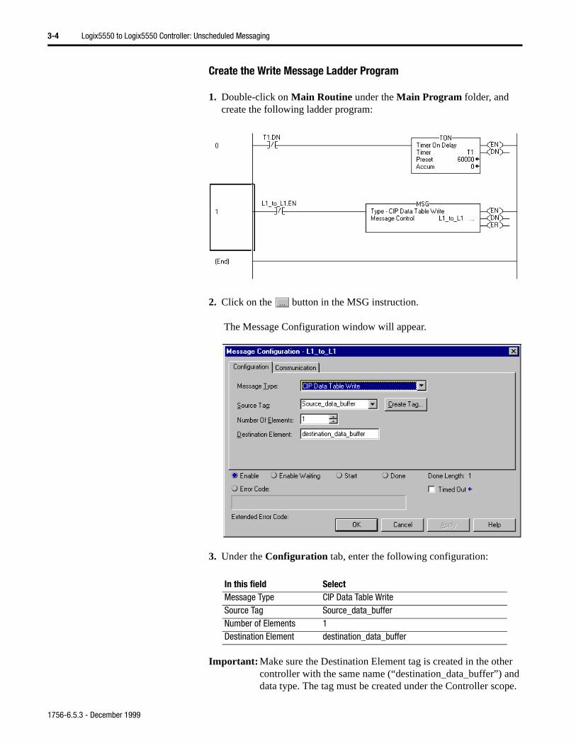
Create the Write Message Ladder Program
1. Double-click on Main Routine under the Main Program folder, and create the following ladder program:
2. Click on the button in the MSG instruction.
The Message Configuration window will appear.
3. Under the Configuration tab, enter the following configuration:
Important: Make sure the Destination Element tag is created in the other controller with the same name (“destination_data_buffer”) adata type. The tag must be created under the Controller sco
In this field SelectMessage Type CIP Data Table WriteSource Tag Source_data_bufferNumber of Elements 1Destination Element destination_data_buffer
1756-6.5.3 - December 1999
Logix5550 to Logix5550 Controller: Unscheduled Messaging 3-5
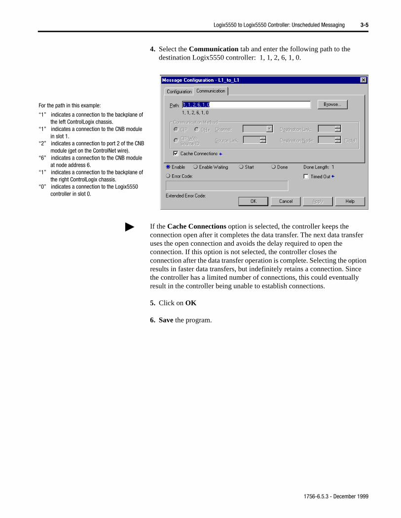
4. Select the Communication tab and enter the following path to the destination Logix5550 controller: 1, 1, 2, 6, 1, 0.
5. Click on OK
6. Save the program.
For the path in this example:
“1” indicates a connection to the backplane of the left ControlLogix chassis.
“1” indicates a connection to the CNB module in slot 1.
“2” indicates a connection to port 2 of the CNB module (get on the ControlNet wire).
“6” indicates a connection to the CNB module at node address 6.
“1” indicates a connection to the backplane of the right ControlLogix chassis.
“0” indicates a connection to the Logix5550 controller in slot 0.
If the Cache Connections option is selected, the controller keeps the connection open after it completes the data transfer. The next data transfer uses the open connection and avoids the delay required to open the connection. If this option is not selected, the controller closes the connection after the data transfer operation is complete. Selecting the option results in faster data transfers, but indefinitely retains a connection. Since the controller has a limited number of connections, this could eventually result in the controller being unable to establish connections.
1756-6.5.3 - December 1999
3-6 Logix5550 to Logix5550 Controller: Unscheduled Messaging
Download and Run the Program(1)
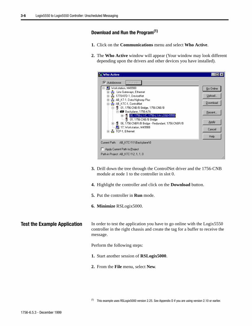
1. Click on the Communications menu and select Who Active.
2. The Who Active window will appear (Your window may look different depending upon the drivers and other devices you have installed).
3. Drill down the tree through the ControlNet driver and the 1756-CNB module at node 1 to the controller in slot 0.
4. Highlight the controller and click on the Download button.
5. Put the controller in Run mode.
6. Minimize RSLogix5000.
Test the Example Application In order to test the application you have to go online with the Logix5550 controller in the right chassis and create the tag for a buffer to receive the message.
Perform the following steps:
1. Start another session of RSLogix5000.
2. From the File menu, select New.
(1) This example uses RSLogix5000 version 2.25. See Appendix D if you are using version 2.10 or earlier.
1756-6.5.3 - December 1999
Logix5550 to Logix5550 Controller: Unscheduled Messaging 3-7
The New Controller window will appear.
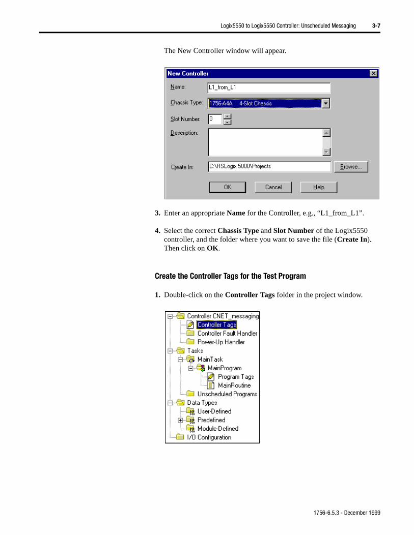
3. Enter an appropriate Name for the Controller, e.g., “L1_from_L1”.
4. Select the correct Chassis Type and Slot Number of the Logix5550 controller, and the folder where you want to save the file (Create In). Then click on OK.
Create the Controller Tags for the Test Program
1. Double-click on the Controller Tags folder in the project window.
1756-6.5.3 - December 1999
3-8 Logix5550 to Logix5550 Controller: Unscheduled Messaging
The Controller Tags window will appear.
2. Select the Edit Tags tab and create the following tags:
Tag Name Type Style
destination_data_buffer DINT Decimal
1756-6.5.3 - December 1999
Logix5550 to Logix5550 Controller: Unscheduled Messaging 3-9
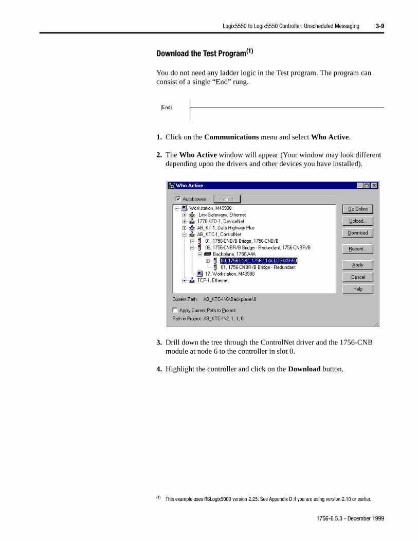
Download the Test Program(1)
You do not need any ladder logic in the Test program. The program can consist of a single “End” rung.
1. Click on the Communications menu and select Who Active.
2. The Who Active window will appear (Your window may look different depending upon the drivers and other devices you have installed).
3. Drill down the tree through the ControlNet driver and the 1756-CNB module at node 6 to the controller in slot 0.
4. Highlight the controller and click on the Download button.
(1) This example uses RSLogix5000 version 2.25. See Appendix D if you are using version 2.10 or earlier.
1756-6.5.3 - December 1999
3-10 Logix5550 to Logix5550 Controller: Unscheduled Messaging
Test the Communications
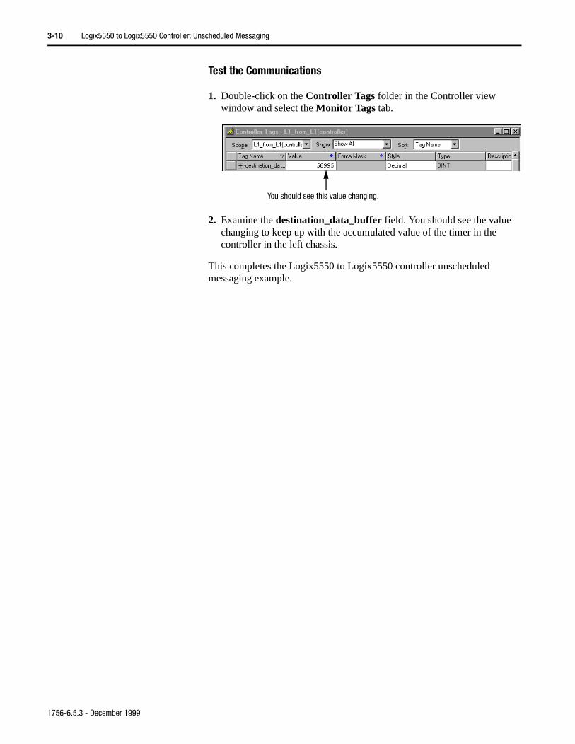
1. Double-click on the Controller Tags folder in the Controller view window and select the Monitor Tags tab.
2. Examine the destination_data_buffer field. You should see the value changing to keep up with the accumulated value of the timer in the controller in the left chassis.
This completes the Logix5550 to Logix5550 controller unscheduled messaging example.
You should see this value changing.
1756-6.5.3 - December 1999
Chapter 4
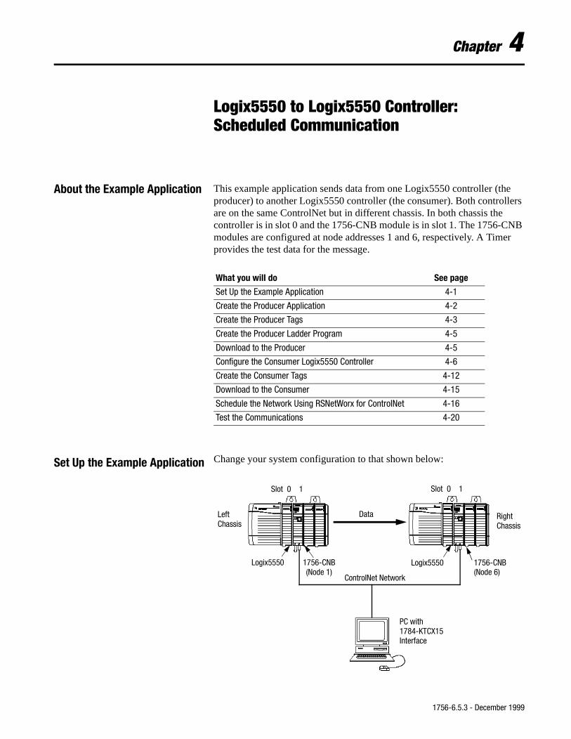
Logix5550 to Logix5550 Controller: Scheduled Communication
About the Example Application This example application sends data from one Logix5550 controller (the producer) to another Logix5550 controller (the consumer). Both controllers are on the same ControlNet but in different chassis. In both chassis the controller is in slot 0 and the 1756-CNB module is in slot 1. The 1756-CNB modules are configured at node addresses 1 and 6, respectively. A Timer provides the test data for the message.
Set Up the Example Application Change your system configuration to that shown below:
What you will do See page
Set Up the Example Application 4-1
Create the Producer Application 4-2
Create the Producer Tags 4-3
Create the Producer Ladder Program 4-5
Download to the Producer 4-5
Configure the Consumer Logix5550 Controller 4-6
Create the Consumer Tags 4-12
Download to the Consumer 4-15
Schedule the Network Using RSNetWorx for ControlNet 4-16
Test the Communications 4-20
ControlNet Network
Logix5550 1756-CNB(Node 1)
1756-CNB(Node 6)
Logix5550
LeftChassis
RightChassis
PC with1784-KTCX15Interface
Data
Slot 0 1 Slot 0 1
1756-6.5.3 - December 1999
4-2 Logix5550 to Logix5550 Controller: Scheduled Communication
• Verify that the Logix5550 controllers and the 1756-CNB modules are in slots 0 and 1 in each ControlLogix chassis, as shown.
• Verify that the node addresses for the 1756-CNB modules are 1 and 6 as shown.
• Verify that the KTCX15 driver card is configured as described on page 2-3.
• Verify that all wiring and cabling is properly connected.
Create the Producer Application
Perform the following steps to create the producer application.
1. Open the RSLogix5000 software.
2. From the File menu, select New. The New Controller window will appear.
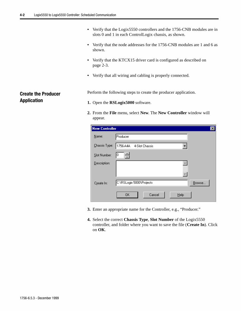
3. Enter an appropriate name for the Controller, e.g., “Producer.”
4. Select the correct Chassis Type, Slot Number of the Logix5550 controller, and folder where you want to save the file (Create In). Click on OK.
1756-6.5.3 - December 1999
Logix5550 to Logix5550 Controller: Scheduled Communication 4-3
Create the Producer Tags
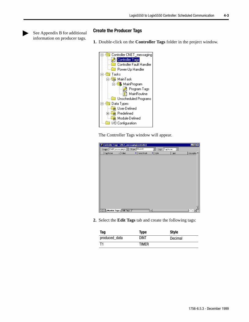
1. Double-click on the Controller Tags folder in the project window.
The Controller Tags window will appear.
2. Select the Edit Tags tab and create the following tags:
Tag Type Styleproduced_data DINT Decimal
T1 TIMER
See Appendix B for additional information on producer tags.
1756-6.5.3 - December 1999
4-4 Logix5550 to Logix5550 Controller: Scheduled Communication
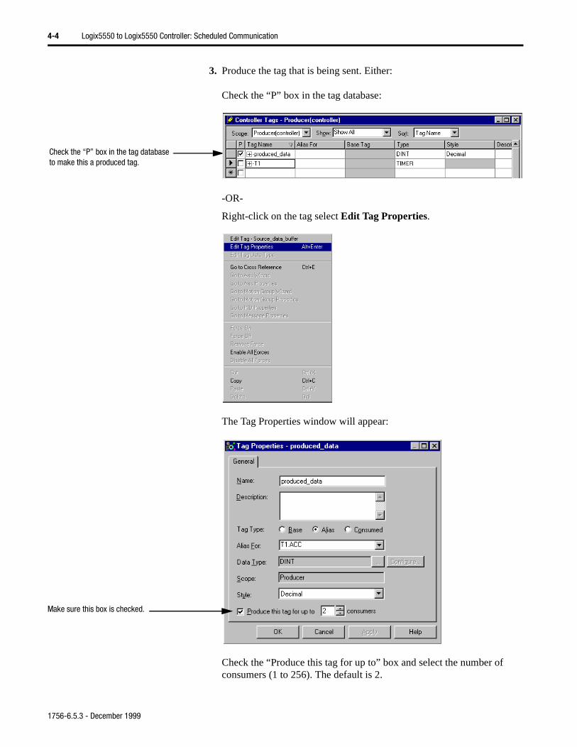
3. Produce the tag that is being sent. Either:
Check the “P” box in the tag database:
-OR-
Right-click on the tag select Edit Tag Properties.
The Tag Properties window will appear:
Check the “Produce this tag for up to” box and select the number of consumers (1 to 256). The default is 2.
Check the “P” box in the tag database to make this a produced tag.
Make sure this box is checked.
1756-6.5.3 - December 1999
Logix5550 to Logix5550 Controller: Scheduled Communication 4-5
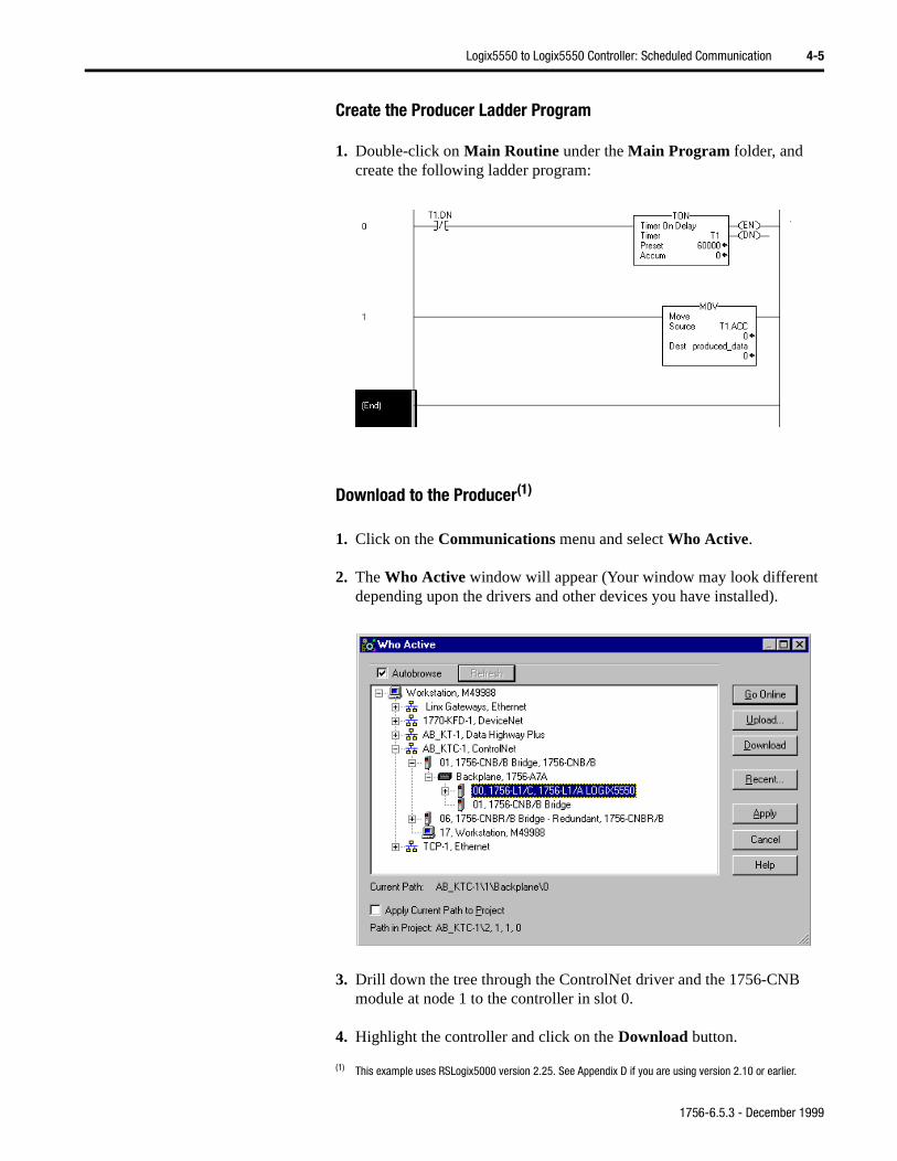
Create the Producer Ladder Program
1. Double-click on Main Routine under the Main Program folder, and create the following ladder program:
Download to the Producer(1)
1. Click on the Communications menu and select Who Active.
2. The Who Active window will appear (Your window may look different depending upon the drivers and other devices you have installed).
3. Drill down the tree through the ControlNet driver and the 1756-CNB module at node 1 to the controller in slot 0.
4. Highlight the controller and click on the Download button.
(1) This example uses RSLogix5000 version 2.25. See Appendix D if you are using version 2.10 or earlier.
1756-6.5.3 - December 1999
4-6 Logix5550 to Logix5550 Controller: Scheduled Communication
NB
a
5. Put the controller in Run mode.
6. Minimize RSLogix5000.
Configure the Consumer Logix5550 Controller
In order to test the application you have to create a consumer controller, add the producer controller to the I/O configuration of the consumer controller, and create a consumed tag to receive the data.
Perform the following steps to create the consumer controller:
1. Start another session of RSLogix5000.
2. From the File menu, select New.
The New Controller window will appear.
3. Enter an appropriate Name for the Controller, e.g., “Consumer.”
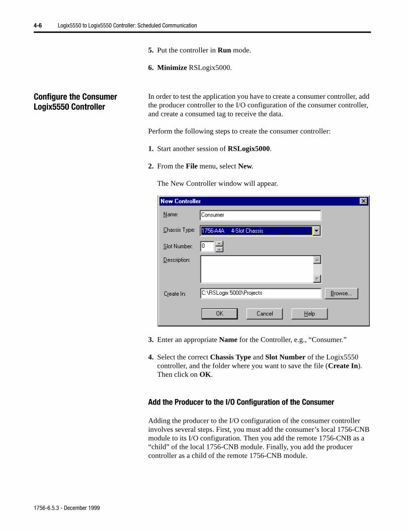
4. Select the correct Chassis Type and Slot Number of the Logix5550 controller, and the folder where you want to save the file (Create In). Then click on OK.
Add the Producer to the I/O Configuration of the Consumer
Adding the producer to the I/O configuration of the consumer controllerinvolves several steps. First, you must add the consumer’s local 1756-Cmodule to its I/O configuration. Then you add the remote 1756-CNB as“child” of the local 1756-CNB module. Finally, you add the producer controller as a child of the remote 1756-CNB module.
1756-6.5.3 - December 1999
Logix5550 to Logix5550 Controller: Scheduled Communication 4-7
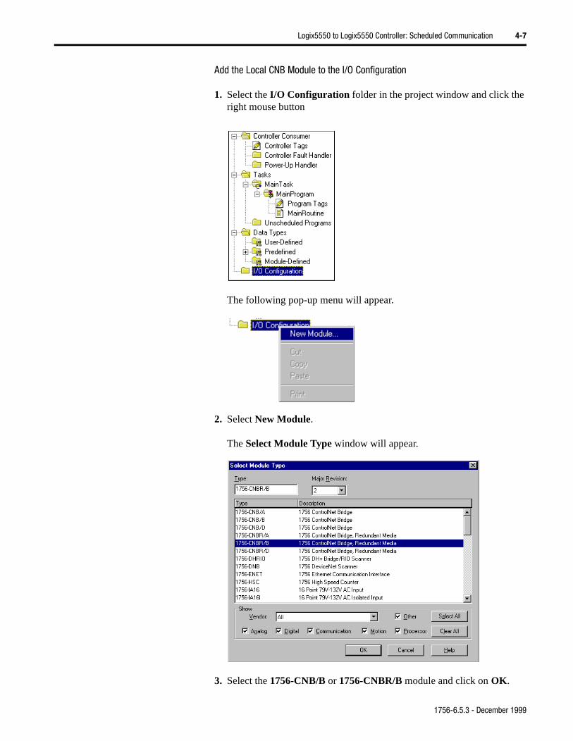
Add the Local CNB Module to the I/O Configuration
1. Select the I/O Configuration folder in the project window and click the right mouse button
The following pop-up menu will appear.
2. Select New Module.
The Select Module Type window will appear.
3. Select the 1756-CNB/B or 1756-CNBR/B module and click on OK.
1756-6.5.3 - December 1999
4-8 Logix5550 to Logix5550 Controller: Scheduled Communication
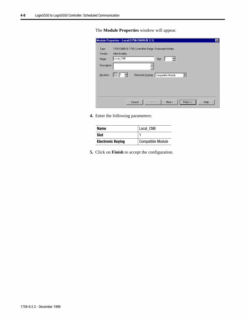
The Module Properties window will appear.
4. Enter the following parameters:
5. Click on Finish to accept the configuration.
Name Local_CNB
Slot 1
Electronic Keying Compatible Module
1756-6.5.3 - December 1999
Logix5550 to Logix5550 Controller: Scheduled Communication 4-9
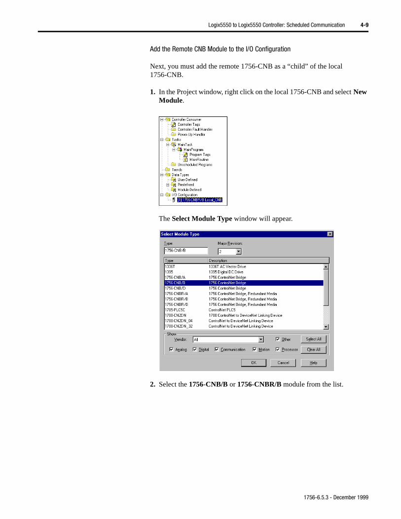
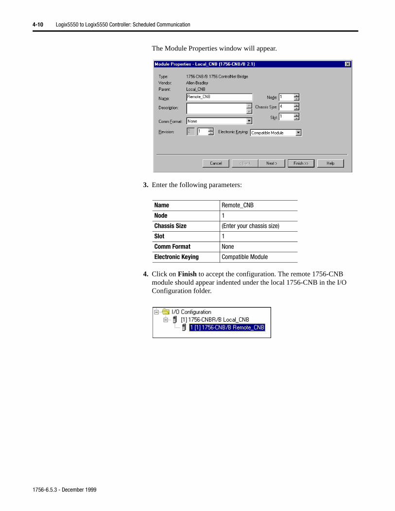
Add the Remote CNB Module to the I/O Configuration
Next, you must add the remote 1756-CNB as a “child” of the local 1756-CNB.
1. In the Project window, right click on the local 1756-CNB and select New Module.
The Select Module Type window will appear.
2. Select the 1756-CNB/B or 1756-CNBR/B module from the list.
1756-6.5.3 - December 1999
4-10 Logix5550 to Logix5550 Controller: Scheduled Communication
The Module Properties window will appear.
3. Enter the following parameters:
4. Click on Finish to accept the configuration. The remote 1756-CNB module should appear indented under the local 1756-CNB in the I/O Configuration folder.
Name Remote_CNB
Node 1
Chassis Size (Enter your chassis size)
Slot 1
Comm Format None
Electronic Keying Compatible Module
1756-6.5.3 - December 1999
Logix5550 to Logix5550 Controller: Scheduled Communication 4-11
Add the Remote Controller to the I/O Configuration
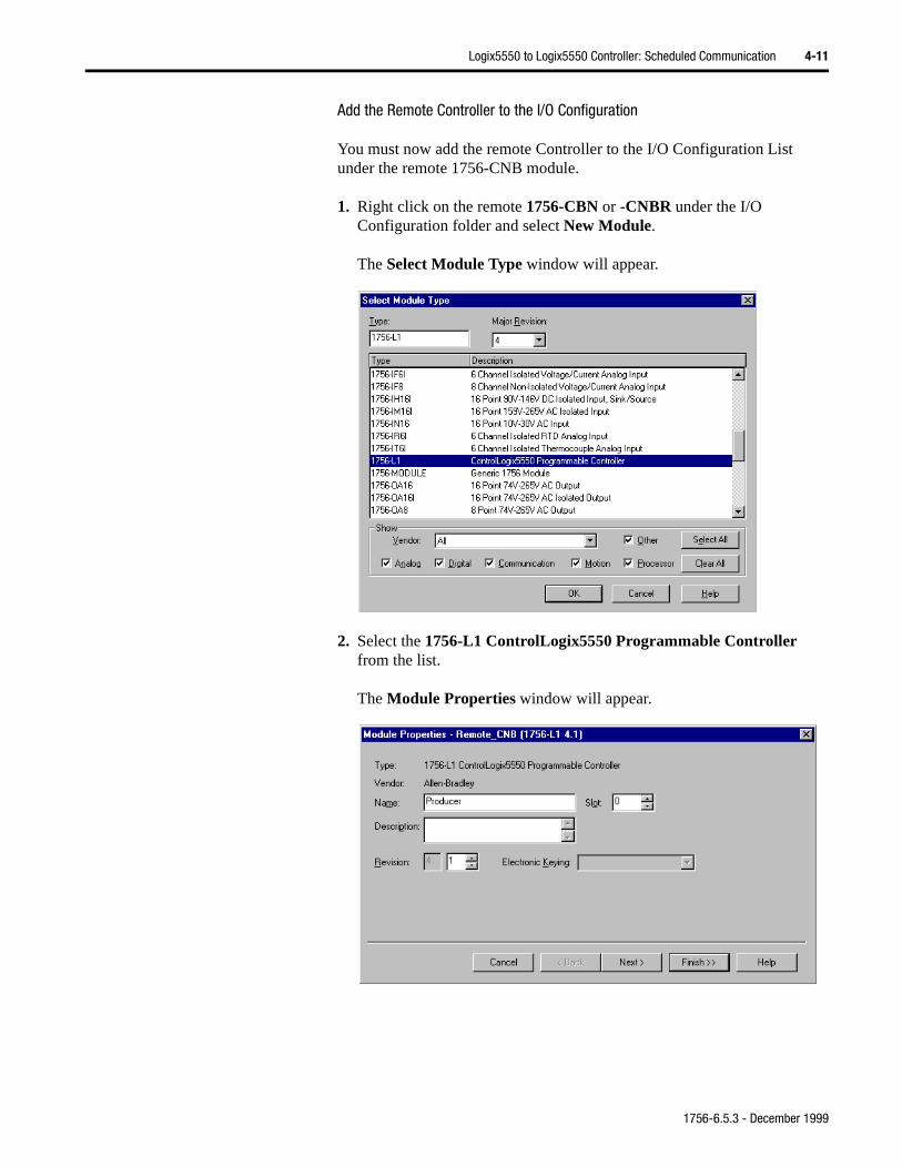
You must now add the remote Controller to the I/O Configuration List under the remote 1756-CNB module.
1. Right click on the remote 1756-CBN or -CNBR under the I/O Configuration folder and select New Module.
The Select Module Type window will appear.
2. Select the 1756-L1 ControlLogix5550 Programmable Controller from the list.
The Module Properties window will appear.
1756-6.5.3 - December 1999
4-12 Logix5550 to Logix5550 Controller: Scheduled Communication
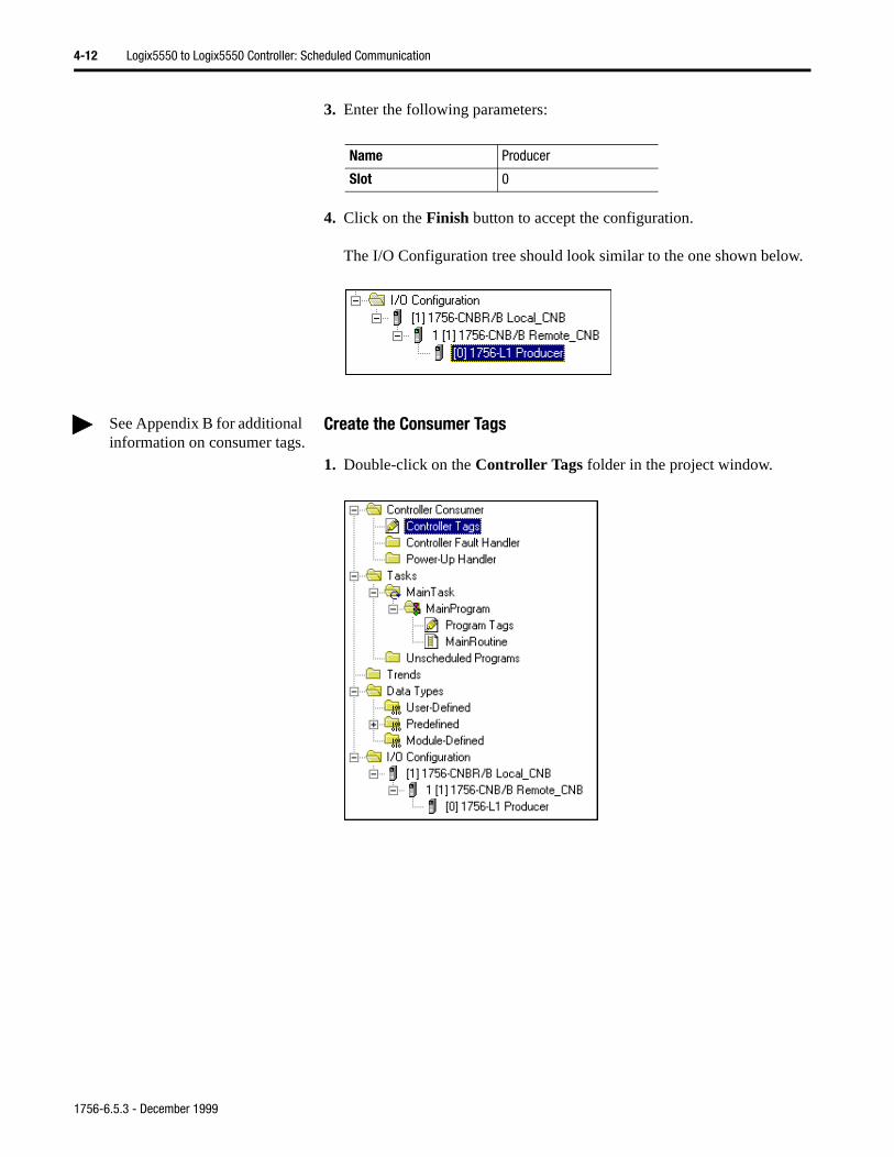
3. Enter the following parameters:
4. Click on the Finish button to accept the configuration.
The I/O Configuration tree should look similar to the one shown below.
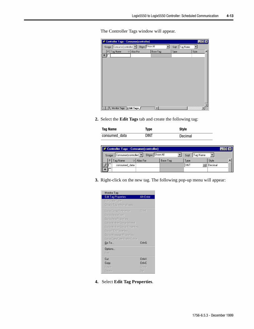
Create the Consumer Tags
1. Double-click on the Controller Tags folder in the project window.
Name Producer
Slot 0
See Appendix B for additional information on consumer tags.
1756-6.5.3 - December 1999
Logix5550 to Logix5550 Controller: Scheduled Communication 4-13
The Controller Tags window will appear.
2. Select the Edit Tags tab and create the following tag:
3. Right-click on the new tag. The following pop-up menu will appear:
4. Select Edit Tag Properties.
Tag Name Type Style
consumed_data DINT Decimal
1756-6.5.3 - December 1999
4-14 Logix5550 to Logix5550 Controller: Scheduled Communication
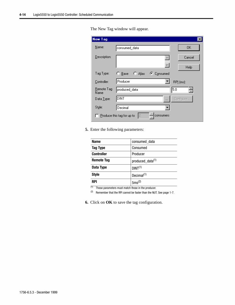
The New Tag window will appear.
5. Enter the following parameters:
6. Click on OK to save the tag configuration.
Name consumed_data
Tag Type Consumed
Controller Producer
Remote Tag produced_data(1)
(1) These parameters must match those in the producer.
Data Type DINT(1)
Style Decimal(1)
RPI 5ms(2)
(2) Remember that the RPI cannot be faster than the NUT. See page 1-7.
1756-6.5.3 - December 1999
Logix5550 to Logix5550 Controller: Scheduled Communication 4-15
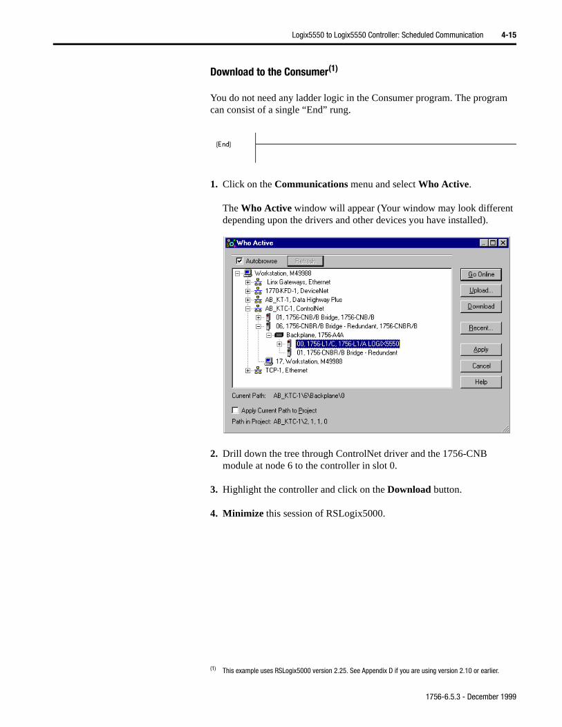
Download to the Consumer(1)
You do not need any ladder logic in the Consumer program. The program can consist of a single “End” rung.
1. Click on the Communications menu and select Who Active.
The Who Active window will appear (Your window may look different depending upon the drivers and other devices you have installed).
2. Drill down the tree through ControlNet driver and the 1756-CNB module at node 6 to the controller in slot 0.
3. Highlight the controller and click on the Download button.
4. Minimize this session of RSLogix5000.
(1) This example uses RSLogix5000 version 2.25. See Appendix D if you are using version 2.10 or earlier.
1756-6.5.3 - December 1999
4-16 Logix5550 to Logix5550 Controller: Scheduled Communication
Schedule the Network Using RSNetWorx for ControlNet
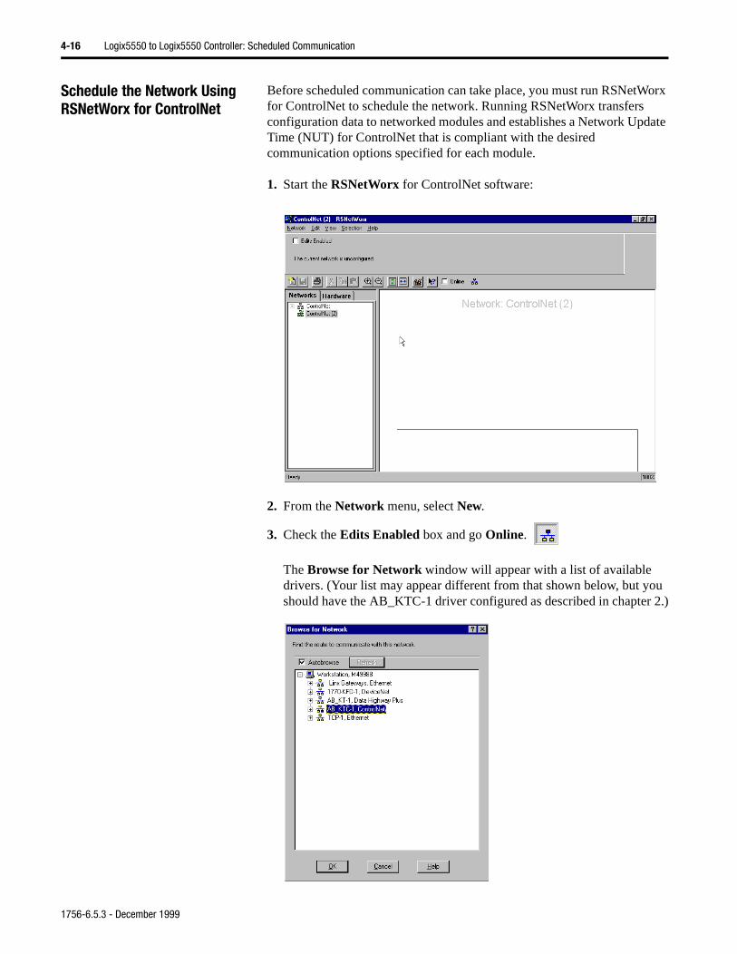
Before scheduled communication can take place, you must run RSNetWorx for ControlNet to schedule the network. Running RSNetWorx transfers configuration data to networked modules and establishes a Network Update Time (NUT) for ControlNet that is compliant with the desired communication options specified for each module.
1. Start the RSNetWorx for ControlNet software:
2. From the Network menu, select New.
3. Check the Edits Enabled box and go Online.
The Browse for Network window will appear with a list of available drivers. (Your list may appear different from that shown below, but you should have the AB_KTC-1 driver configured as described in chapter 2.)
1756-6.5.3 - December 1999
Logix5550 to Logix5550 Controller: Scheduled Communication 4-17
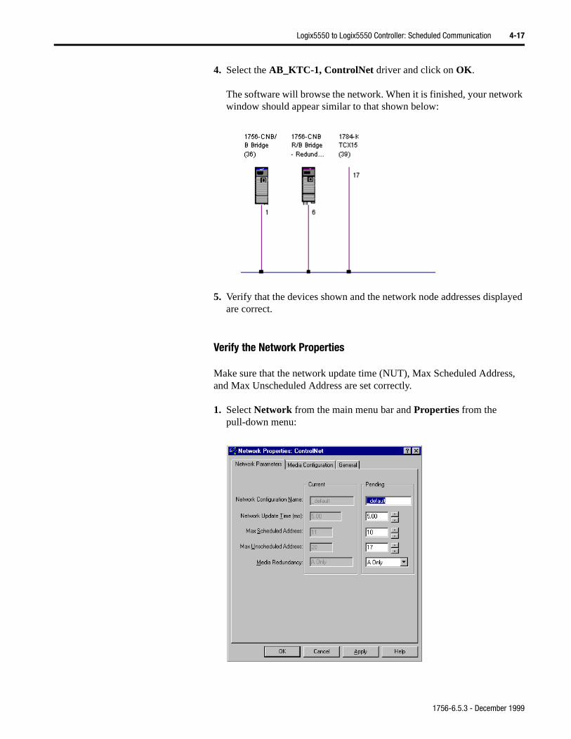
4. Select the AB_KTC-1, ControlNet driver and click on OK.
The software will browse the network. When it is finished, your network window should appear similar to that shown below:
5. Verify that the devices shown and the network node addresses displayed are correct.
Verify the Network Properties
Make sure that the network update time (NUT), Max Scheduled Address, and Max Unscheduled Address are set correctly.
1. Select Network from the main menu bar and Properties from the pull-down menu:
1756-6.5.3 - December 1999
4-18 Logix5550 to Logix5550 Controller: Scheduled Communication
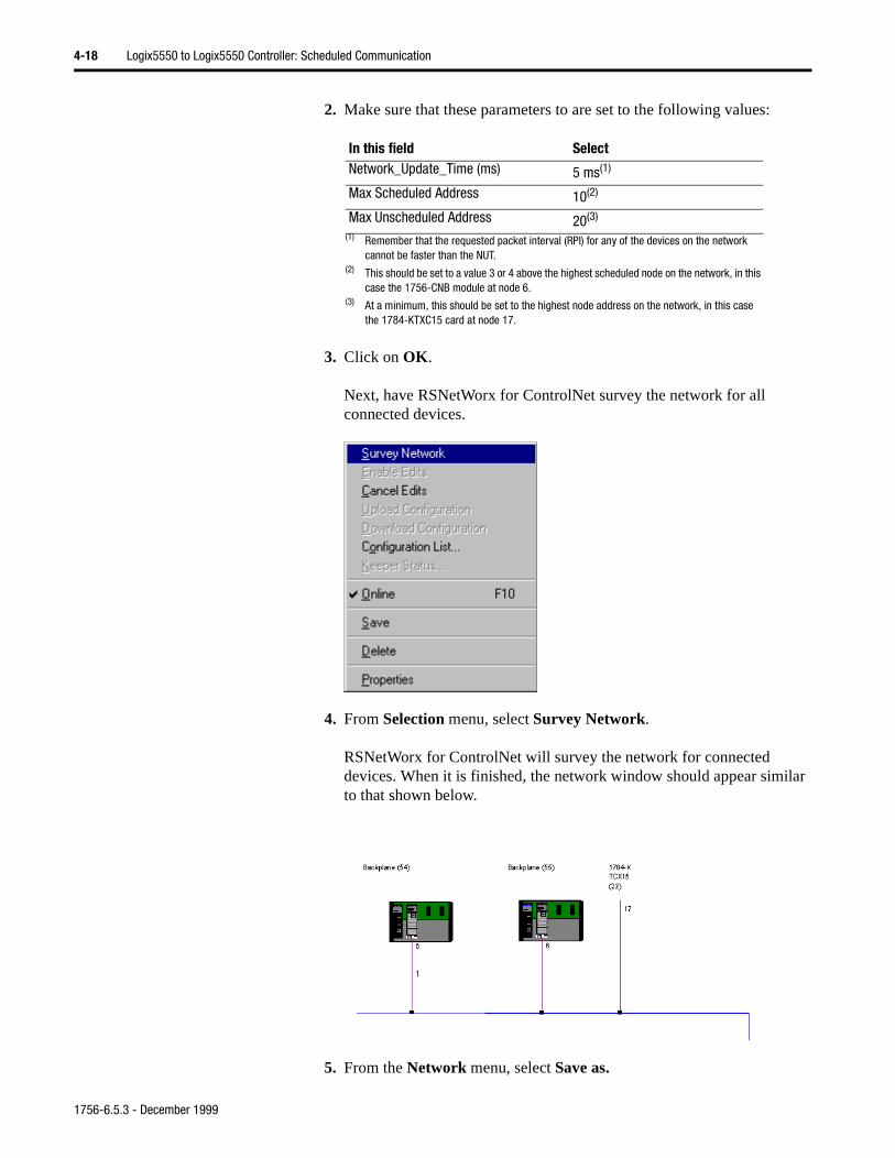
2. Make sure that these parameters to are set to the following values:
3. Click on OK.
Next, have RSNetWorx for ControlNet survey the network for all connected devices.
4. From Selection menu, select Survey Network.
RSNetWorx for ControlNet will survey the network for connected devices. When it is finished, the network window should appear similar to that shown below.
5. From the Network menu, select Save as.
In this field SelectNetwork_Update_Time (ms) 5 ms(1)
(1) Remember that the requested packet interval (RPI) for any of the devices on the network cannot be faster than the NUT.
Max Scheduled Address 10(2)
(2) This should be set to a value 3 or 4 above the highest scheduled node on the network, in this case the 1756-CNB module at node 6.
Max Unscheduled Address 20(3)
(3) At a minimum, this should be set to the highest node address on the network, in this case the 1784-KTXC15 card at node 17.
1
1756-6.5.3 - December 1999
Logix5550 to Logix5550 Controller: Scheduled Communication 4-19
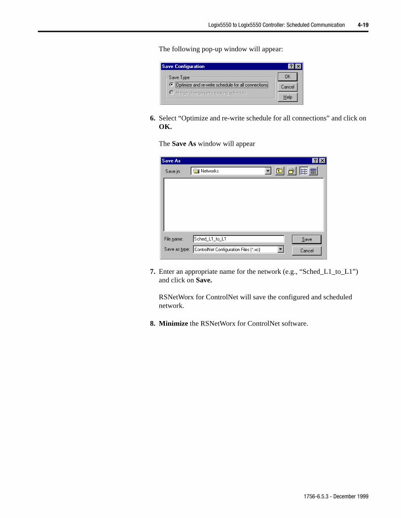
on
The following pop-up window will appear:
6. Select “Optimize and re-write schedule for all connections” and click OK.
The Save As window will appear
7. Enter an appropriate name for the network (e.g., “Sched_L1_to_L1”)and click on Save.
RSNetWorx for ControlNet will save the configured and scheduled network.
8. Minimize the RSNetWorx for ControlNet software.
1756-6.5.3 - December 1999
4-20 Logix5550 to Logix5550 Controller: Scheduled Communication
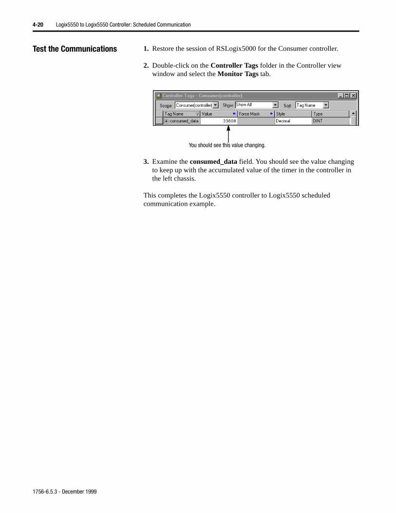
Test the Communications 1. Restore the session of RSLogix5000 for the Consumer controller.
2. Double-click on the Controller Tags folder in the Controller view window and select the Monitor Tags tab.
3. Examine the consumed_data field. You should see the value changing to keep up with the accumulated value of the timer in the controller in the left chassis.
This completes the Logix5550 controller to Logix5550 scheduled communication example.
You should see this value changing.
1756-6.5.3 - December 1999
Chapter 5
Logix5550 Controller to PLC-5C:Unscheduled Messaging
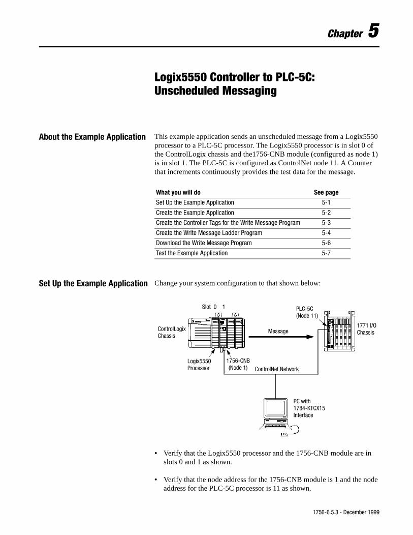
About the Example Application This example application sends an unscheduled message from a Logix5550 processor to a PLC-5C processor. The Logix5550 processor is in slot 0 of the ControlLogix chassis and the1756-CNB module (configured as node 1) is in slot 1. The PLC-5C is configured as ControlNet node 11. A Counter that increments continuously provides the test data for the message.
Set Up the Example Application Change your system configuration to that shown below:
• Verify that the Logix5550 processor and the 1756-CNB module are in slots 0 and 1 as shown.
• Verify that the node address for the 1756-CNB module is 1 and the node address for the PLC-5C processor is 11 as shown.
What you will do See page
Set Up the Example Application 5-1
Create the Example Application 5-2
Create the Controller Tags for the Write Message Program 5-3
Create the Write Message Ladder Program 5-4
Download the Write Message Program 5-6
Test the Example Application 5-7
ControlNet NetworkLogix5550 1756-CNB
(Node 1)
PLC-5C
ControlLogixChassis
1771 I/OChassis
PC with1784-KTCX15Interface
Message
Slot 0 1
(Node 11)
Processor
1756-6.5.3 - December 1999
5-2 Logix5550 Controller to PLC-5C: Unscheduled Messaging
g.”
• Verify that the KTCX15 driver card is configured as described on page 2-3.
• Verify that all wiring and cabling is properly connected.
Create the Example Application Perform the following steps to create the example application:
1. Open the RSLogix5000 software.
2. From the File menu, select New. The New Controller pop-up window will appear.
3. Enter an appropriate name for the Controller, e.g., “CNET_Messagin
4. Select the correct Chassis Type, Slot Number of the Logix5550 processor, and folder where you want to save the file (Create In). Click on OK.
1756-6.5.3 - December 1999
Logix5550 Controller to PLC-5C: Unscheduled Messaging 5-3
Create the Controller Tags for the Write Message Program
You must create a source tag for the message under the controller scope and assign it the same data type as the destination element (e.g., INT).
1. Double-click on the Controller Tags folder in the Project window.
The Controller Tags window will appear.
2. Select the Edit Tags tab and create the following tags:
Tag Alias For Type StyleSUM INT DecimalPLUS_ONE INT DecimalL1_to_PLC5 MESSAGEMssg_to_PLC5 SUM INT Decimal
1756-6.5.3 - December 1999
5-4 Logix5550 Controller to PLC-5C: Unscheduled Messaging
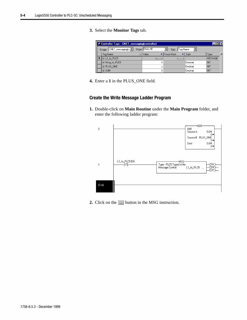
3. Select the Monitor Tags tab.
4. Enter a 1 in the PLUS_ONE field.
Create the Write Message Ladder Program
1. Double-click on Main Routine under the Main Program folder, and enter the following ladder program:
2. Click on the button in the MSG instruction.
1756-6.5.3 - December 1999
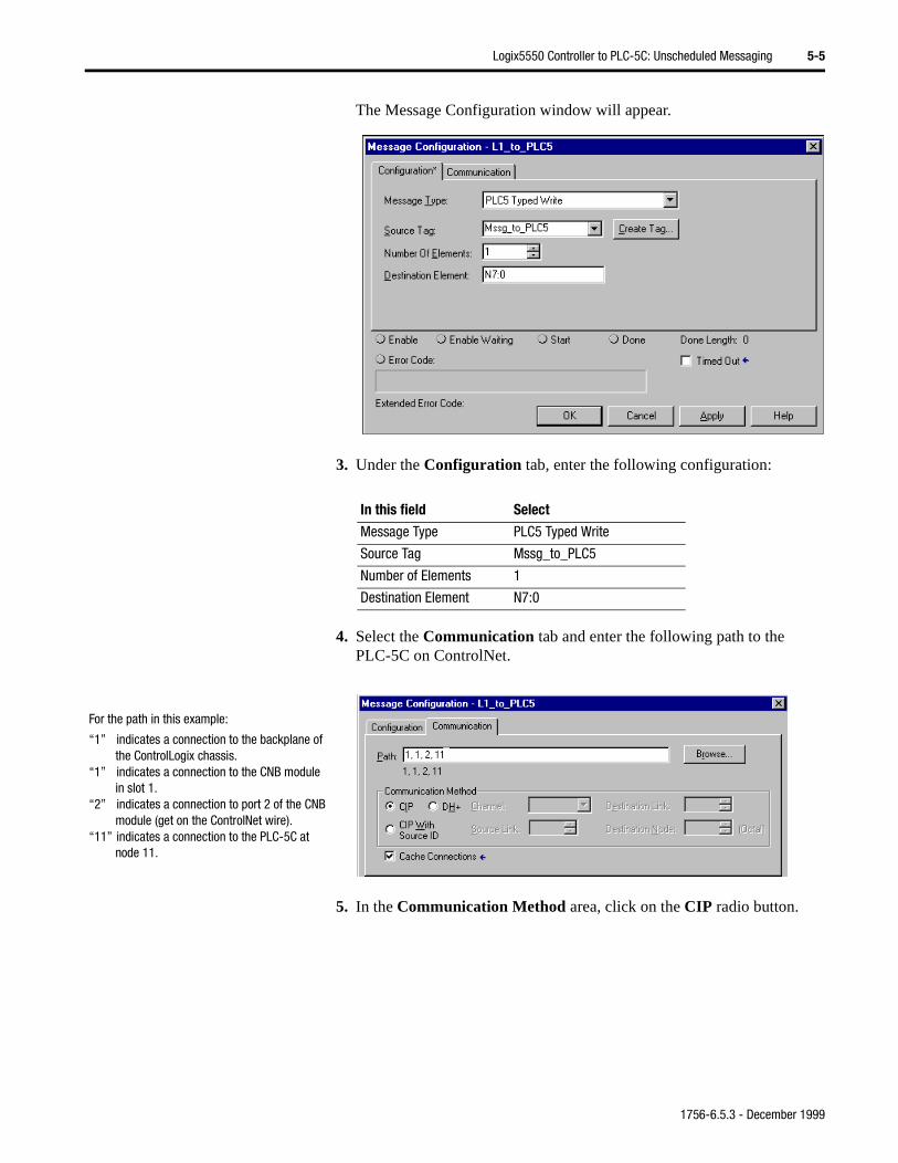
Logix5550 Controller to PLC-5C: Unscheduled Messaging 5-5
The Message Configuration window will appear.
3. Under the Configuration tab, enter the following configuration:
4. Select the Communication tab and enter the following path to the PLC-5C on ControlNet.
5. In the Communication Method area, click on the CIP radio button.
In this field Select
Message Type PLC5 Typed Write
Source Tag Mssg_to_PLC5
Number of Elements 1
Destination Element N7:0
For the path in this example:
“1” indicates a connection to the backplane of the ControlLogix chassis.
“1” indicates a connection to the CNB module in slot 1.
“2” indicates a connection to port 2 of the CNB module (get on the ControlNet wire).
“11” indicates a connection to the PLC-5C at node 11.
1756-6.5.3 - December 1999
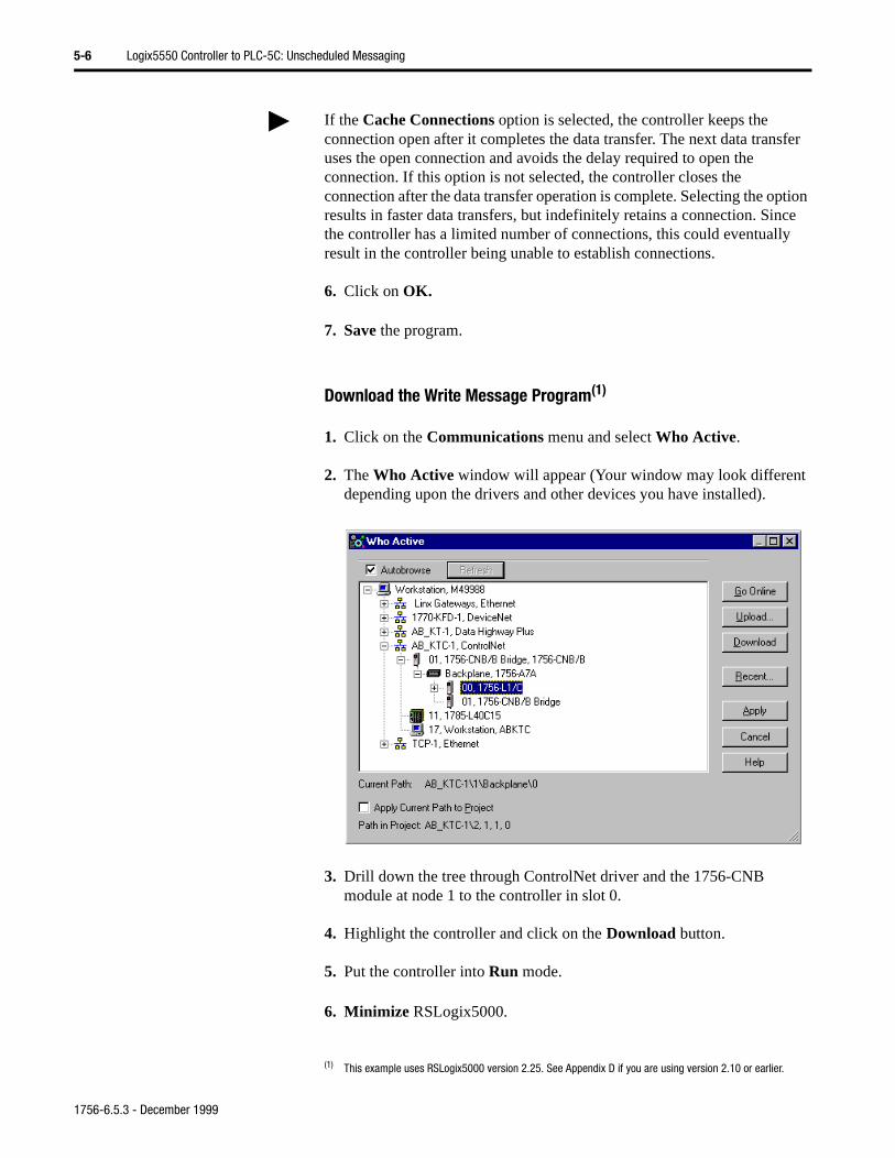
5-6 Logix5550 Controller to PLC-5C: Unscheduled Messaging
6. Click on OK.
7. Save the program.
Download the Write Message Program(1)
1. Click on the Communications menu and select Who Active.
2. The Who Active window will appear (Your window may look different depending upon the drivers and other devices you have installed).
3. Drill down the tree through ControlNet driver and the 1756-CNB module at node 1 to the controller in slot 0.
4. Highlight the controller and click on the Download button.
5. Put the controller into Run mode.
6. Minimize RSLogix5000.
If the Cache Connections option is selected, the controller keeps the connection open after it completes the data transfer. The next data transfer uses the open connection and avoids the delay required to open the connection. If this option is not selected, the controller closes the connection after the data transfer operation is complete. Selecting the option results in faster data transfers, but indefinitely retains a connection. Since the controller has a limited number of connections, this could eventually result in the controller being unable to establish connections.
(1) This example uses RSLogix5000 version 2.25. See Appendix D if you are using version 2.10 or earlier.
1756-6.5.3 - December 1999
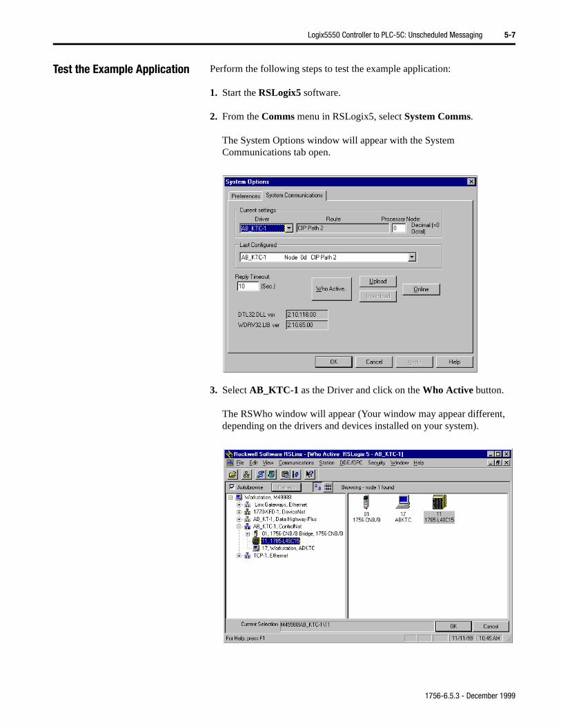
Logix5550 Controller to PLC-5C: Unscheduled Messaging 5-7
Test the Example Application Perform the following steps to test the example application:
1. Start the RSLogix5 software.
2. From the Comms menu in RSLogix5, select System Comms.
The System Options window will appear with the System Communications tab open.
3. Select AB_KTC-1 as the Driver and click on the Who Active button.
The RSWho window will appear (Your window may appear different, depending on the drivers and devices installed on your system).
1756-6.5.3 - December 1999
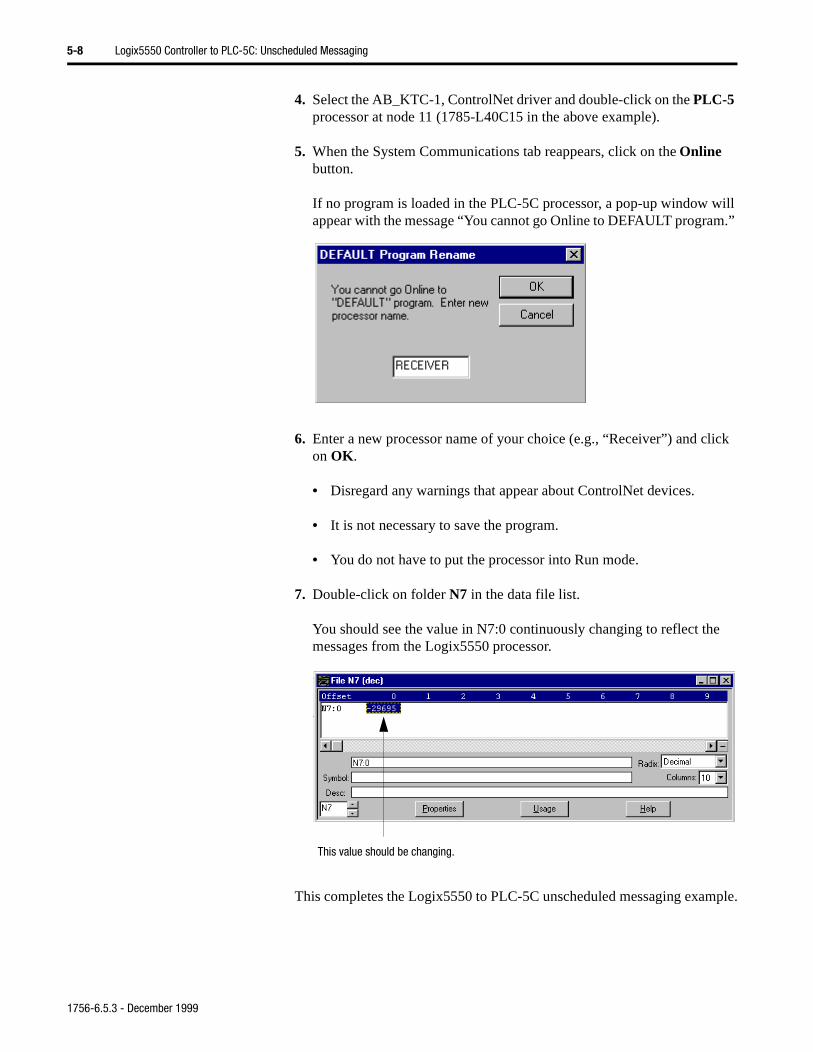
5-8 Logix5550 Controller to PLC-5C: Unscheduled Messaging
m.”
ick
4. Select the AB_KTC-1, ControlNet driver and double-click on the PLC-5 processor at node 11 (1785-L40C15 in the above example).
5. When the System Communications tab reappears, click on the Online button.
If no program is loaded in the PLC-5C processor, a pop-up window will appear with the message “You cannot go Online to DEFAULT progra
6. Enter a new processor name of your choice (e.g., “Receiver”) and clon OK.
• Disregard any warnings that appear about ControlNet devices.
• It is not necessary to save the program.
• You do not have to put the processor into Run mode.
7. Double-click on folder N7 in the data file list.
You should see the value in N7:0 continuously changing to reflect the messages from the Logix5550 processor.
This completes the Logix5550 to PLC-5C unscheduled messaging example.
This value should be changing.
1756-6.5.3 - December 1999
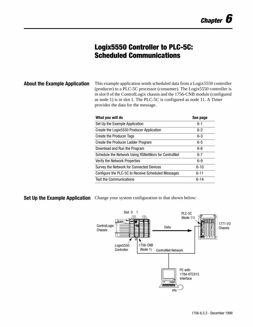
Chapter 6
Logix5550 Controller to PLC-5C:Scheduled Communications
About the Example Application This example application sends scheduled data from a Logix5550 controller (producer) to a PLC-5C processor (consumer). The Logix5550 controller is in slot 0 of the ControlLogix chassis and the 1756-CNB module (configured as node 1) is in slot 1. The PLC-5C is configured as node 11. A Timer provides the data for the message.
Set Up the Example Application Change your system configuration to that shown below:
What you will do See page
Set Up the Example Application 6-1
Create the Logix5550 Producer Application 6-2
Create the Producer Tags 6-3
Create the Producer Ladder Program 6-5
Download and Run the Program 6-6
Schedule the Network Using RSNetWorx for ControlNet 6-7
Verify the Network Properties 6-9
Survey the Network for Connected Devices 6-10
Configure the PLC-5C to Receive Scheduled Messages 6-11
Test the Communications 6-14
ControlNet NetworkLogix5550 1756-CNB
(Node 1)
PLC-5C
ControlLogixChassis
1771 I/OChassis
PC with1784-KTCX15Interface
Data
Slot 0 1
(Node 11)
Controller
1756-6.5.3 - December 1999
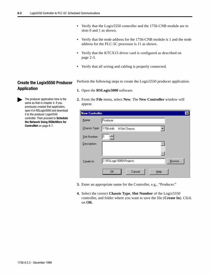
6-2 Logix5550 Controller to PLC-5C: Scheduled Communications
• Verify that the Logix5550 controller and the 1756-CNB module are in slots 0 and 1 as shown.
• Verify that the node address for the 1756-CNB module is 1 and the node address for the PLC-5C processor is 11 as shown.
• Verify that the KTCX15 driver card is configured as described on page 2-3.
• Verify that all wiring and cabling is properly connected.
Create the Logix5550 Producer Application
Perform the following steps to create the Logix5550 producer application.
1. Open the RSLogix5000 software.
2. From the File menu, select New. The New Controller window will appear.
3. Enter an appropriate name for the Controller, e.g., “Producer.”
4. Select the correct Chassis Type, Slot Number of the Logix5550 controller, and folder where you want to save the file (Create In). Click on OK.
The producer application here is the same as that in chapter 4. If you previously created that application, open it in RSLogix5000 and download it to the producer Logix5550 controller. Then proceed to Schedule the Network Using RSNetWorx for ControlNet on page 6-7.
1756-6.5.3 - December 1999
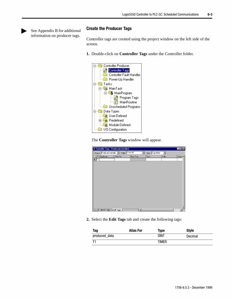
Logix5550 Controller to PLC-5C: Scheduled Communications 6-3
Create the Producer Tags
Controller tags are created using the project window on the left side of the screen.
1. Double-click on Controller Tags under the Controller folder.
The Controller Tags window will appear.
2. Select the Edit Tags tab and create the following tags:
Tag Alias For Type Styleproduced_data DINT Decimal
T1 TIMER
See Appendix B for additional information on producer tags.
1756-6.5.3 - December 1999
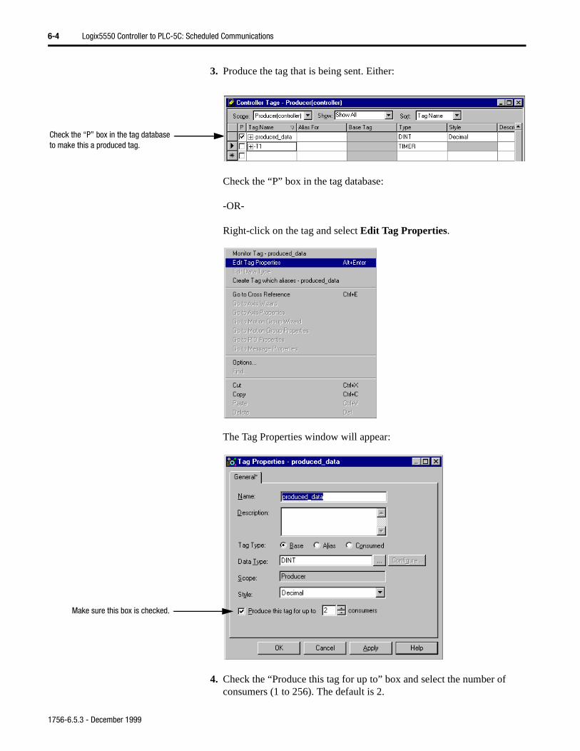
6-4 Logix5550 Controller to PLC-5C: Scheduled Communications
3. Produce the tag that is being sent. Either:
Check the “P” box in the tag database:
-OR-
Right-click on the tag and select Edit Tag Properties.
The Tag Properties window will appear:
4. Check the “Produce this tag for up to” box and select the number of consumers (1 to 256). The default is 2.
Check the “P” box in the tag database to make this a produced tag.
Make sure this box is checked.
1756-6.5.3 - December 1999
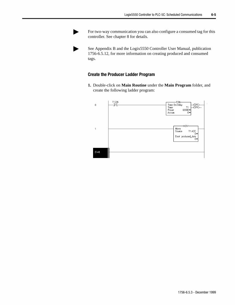
Logix5550 Controller to PLC-5C: Scheduled Communications 6-5
Create the Producer Ladder Program
1. Double-click on Main Routine under the Main Program folder, and create the following ladder program:
For two-way communication you can also configure a consumed tag for this controller. See chapter 8 for details.
See Appendix B and the Logix5550 Controller User Manual, publication 1756-6.5.12, for more information on creating produced and consumed tags.
1756-6.5.3 - December 1999
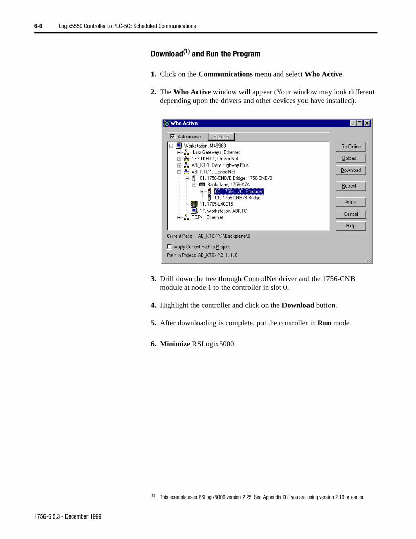
6-6 Logix5550 Controller to PLC-5C: Scheduled Communications
Download(1) and Run the Program
1. Click on the Communications menu and select Who Active.
2. The Who Active window will appear (Your window may look different depending upon the drivers and other devices you have installed).
3. Drill down the tree through ControlNet driver and the 1756-CNB module at node 1 to the controller in slot 0.
4. Highlight the controller and click on the Download button.
5. After downloading is complete, put the controller in Run mode.
6. Minimize RSLogix5000.
(1) This example uses RSLogix5000 version 2.25. See Appendix D if you are using version 2.10 or earlier.
1756-6.5.3 - December 1999
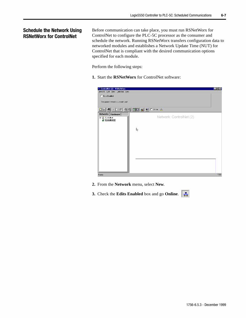
Logix5550 Controller to PLC-5C: Scheduled Communications 6-7
Schedule the Network Using RSNetWorx for ControlNet
Before communication can take place, you must run RSNetWorx for ControlNet to configure the PLC-5C processor as the consumer and schedule the network. Running RSNetWorx transfers configuration data to networked modules and establishes a Network Update Time (NUT) for ControlNet that is compliant with the desired communication options specified for each module.
Perform the following steps:
1. Start the RSNetWorx for ControlNet software:
2. From the Network menu, select New.
3. Check the Edits Enabled box and go Online.
1756-6.5.3 - December 1999
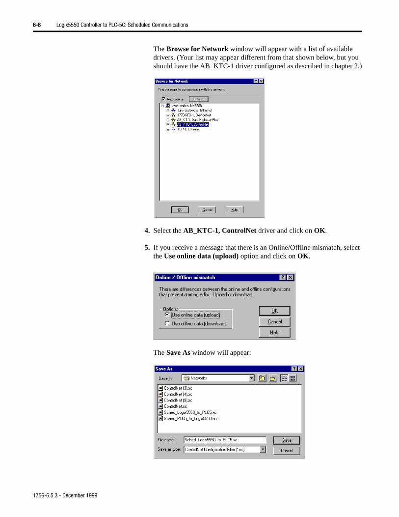
6-8 Logix5550 Controller to PLC-5C: Scheduled Communications
The Browse for Network window will appear with a list of available drivers. (Your list may appear different from that shown below, but you should have the AB_KTC-1 driver configured as described in chapter 2.)
4. Select the AB_KTC-1, ControlNet driver and click on OK.
5. If you receive a message that there is an Online/Offline mismatch, select the Use online data (upload) option and click on OK.
The Save As window will appear:
1756-6.5.3 - December 1999
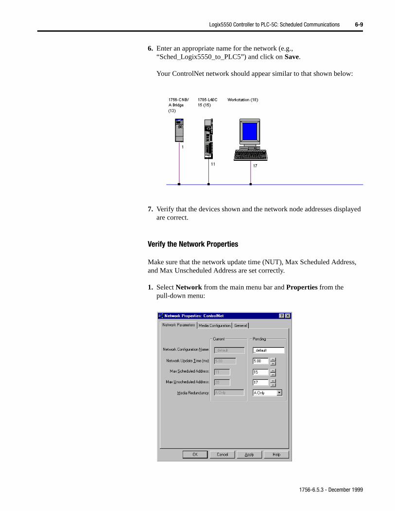
Logix5550 Controller to PLC-5C: Scheduled Communications 6-9
yed
s,
6. Enter an appropriate name for the network (e.g., “Sched_Logix5550_to_PLC5”) and click on Save.
Your ControlNet network should appear similar to that shown below:
7. Verify that the devices shown and the network node addresses displaare correct.
Verify the Network Properties
Make sure that the network update time (NUT), Max Scheduled Addresand Max Unscheduled Address are set correctly.
1. Select Network from the main menu bar and Properties from the pull-down menu:
1756-6.5.3 - December 1999
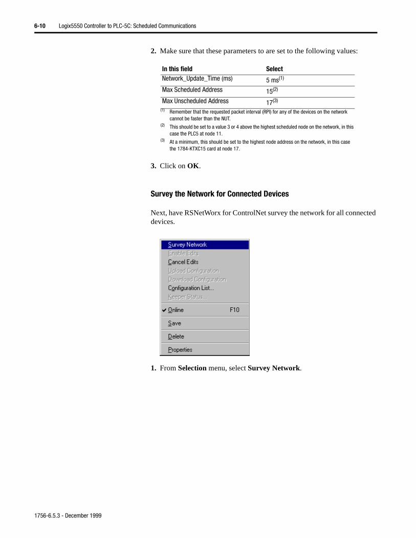
6-10 Logix5550 Controller to PLC-5C: Scheduled Communications
2. Make sure that these parameters to are set to the following values:
3. Click on OK.
Survey the Network for Connected Devices
Next, have RSNetWorx for ControlNet survey the network for all connected devices.
1. From Selection menu, select Survey Network.
In this field SelectNetwork_Update_Time (ms) 5 ms(1)
(1) Remember that the requested packet interval (RPI) for any of the devices on the network cannot be faster than the NUT.
Max Scheduled Address 15(2)
(2) This should be set to a value 3 or 4 above the highest scheduled node on the network, in this case the PLC5 at node 11.
Max Unscheduled Address 17(3)
(3) At a minimum, this should be set to the highest node address on the network, in this case the 1784-KTXC15 card at node 17.
1756-6.5.3 - December 1999
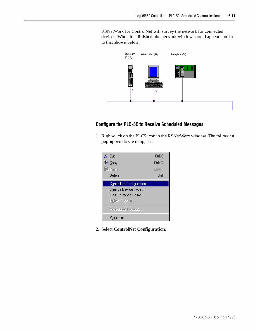
Logix5550 Controller to PLC-5C: Scheduled Communications 6-11
RSNetWorx for ControlNet will survey the network for connected devices. When it is finished, the network window should appear similar to that shown below.
Configure the PLC-5C to Receive Scheduled Messages
1. Right-click on the PLC5 icon in the RSNetWorx window. The following pop-up window will appear:
2. Select ControlNet Configuration.
1756-6.5.3 - December 1999
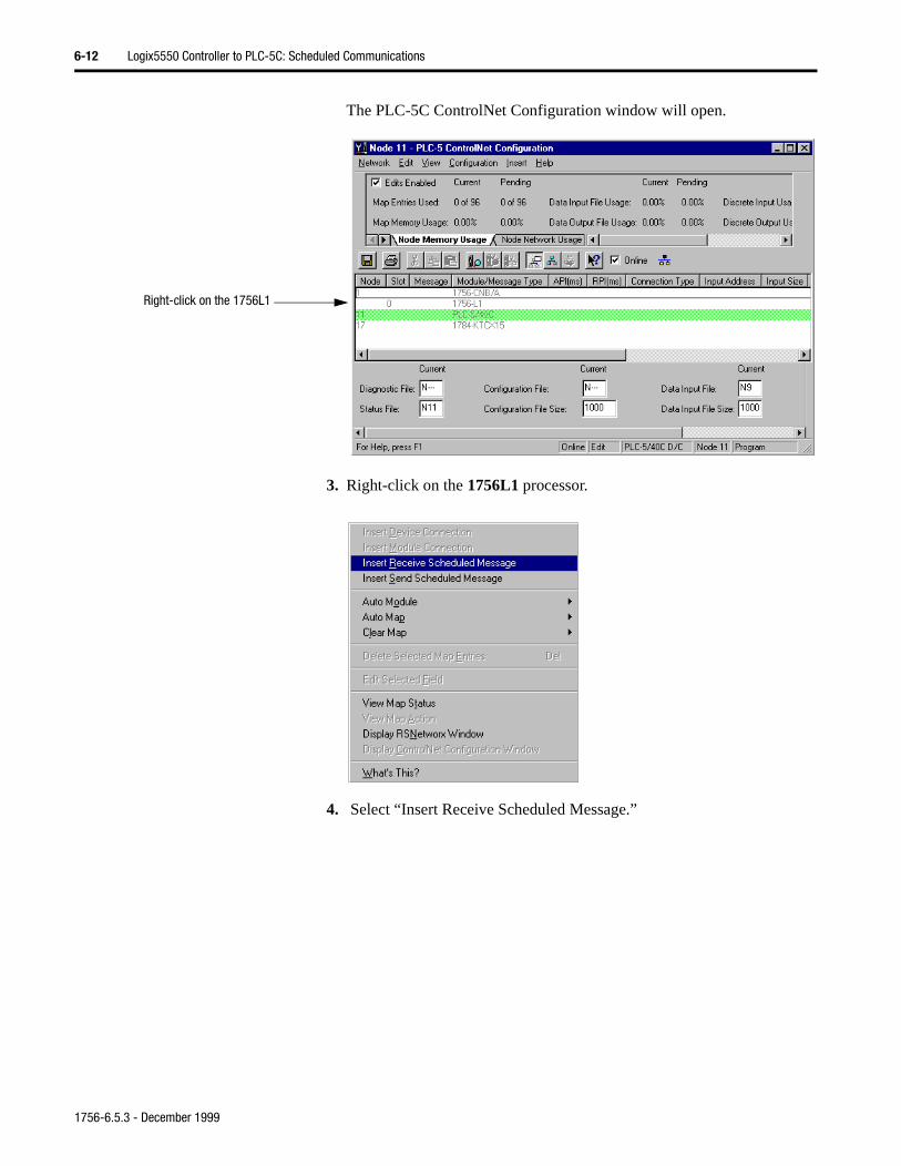
6-12 Logix5550 Controller to PLC-5C: Scheduled Communications
The PLC-5C ControlNet Configuration window will open.
3. Right-click on the 1756L1 processor.
4. Select “Insert Receive Scheduled Message.”
Right-click on the 1756L1
1756-6.5.3 - December 1999
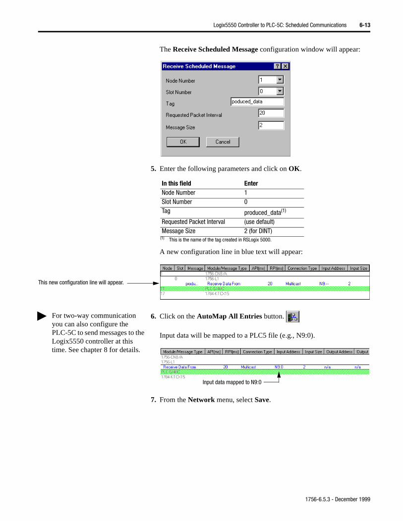
Logix5550 Controller to PLC-5C: Scheduled Communications 6-13
The Receive Scheduled Message configuration window will appear:
5. Enter the following parameters and click on OK.
A new configuration line in blue text will appear:
6. Click on the AutoMap All Entries button.
Input data will be mapped to a PLC5 file (e.g., N9:0).
7. From the Network menu, select Save.
In this field EnterNode Number 1Slot Number 0Tag produced_data(1)
(1) This is the name of the tag created in RSLogix 5000.
Requested Packet Interval (use default)Message Size 2 (for DINT)
This new configuration line will appear.
For two-way communication you can also configure the PLC-5C to send messages to the Logix5550 controller at this time. See chapter 8 for details.
Input data mapped to N9:0
1756-6.5.3 - December 1999
6-14 Logix5550 Controller to PLC-5C: Scheduled Communications
to
The following pop-up window will appear:
8. Select “Optimize and re-write schedule for all connections” and clickon OK.
9. Close the PLC-5 ControlNet Configuration window and Minimize theRSNetWorx for ControlNet software.
Test the Communications You now have the ControlNet network commissioned. Your last task is go online with the PLC-5C to test the communications.
1. Start the RSLogix5 software.
2. From the Comms menu, select System Comms.
The System Options window will appear with the System Communications tab open.
3. Select AB_KTC-1 as the Driver and click on the Who Active button.
1756-6.5.3 - December 1999
Logix5550 Controller to PLC-5C: Scheduled Communications 6-15
.”
d
The RSWho window will appear (Your window may appear different, depending on the drivers and devices installed on your system).
4. Double-click on the PLC-5C processor at node 11 (1785-L40C15 in this example).
5. When the System Communications tab reappears, click on the Online button.
If no program is loaded in the PLC-5C processor, a pop-up window will appear with the message “You cannot go Online to DEFAULT program
6. Enter a new processor name of your choice (e.g., “CONSUMER”) anclick on OK.
1756-6.5.3 - December 1999
6-16 Logix5550 Controller to PLC-5C: Scheduled Communications
ick
You you will receive the following warning:
This warning is telling you that you need to tell RSLogix5 which RSNetWorx for ControlNet project file is associated with this PLC-5 so that the two packages can exchange information about the I/O. You will take care of this shortly.
7. Click on OK.
8. Save the program.
9. Enter an appropriate file name (e.g., “Sched_PLC5_from_L1”) and clon Save.
1756-6.5.3 - December 1999
Logix5550 Controller to PLC-5C: Scheduled Communications 6-17
10.Double-click on Controller Properties in the Project tree.
The Controller Properties window will appear:
11.Verify/Enter the following parameters:
12.Click on the Browse button and Open the RSNetWorx for ControlNet project file created previously (e.g., “Sched_Logix5550_toPLC5.xc”).
13.Click on Apply. Then click on OK.
In this field EnterProcessor Name CONSUMERPLC ControlNet Node 11
1756-6.5.3 - December 1999
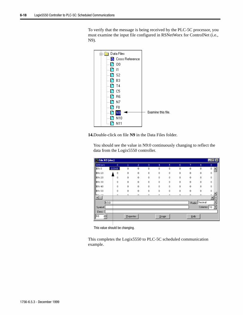
6-18 Logix5550 Controller to PLC-5C: Scheduled Communications
To verify that the message is being received by the PLC-5C processor, you must examine the input file configured in RSNetWorx for ControlNet (i.e., N9).
14.Double-click on file N9 in the Data Files folder.
You should see the value in N9:0 continuously changing to reflect the data from the Logix5550 controller.
This completes the Logix5550 to PLC-5C scheduled communication example.
Examine this file.
This value should be changing.
1756-6.5.3 - December 1999
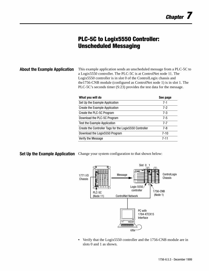
Chapter 7
PLC-5C to Logix5550 Controller:Unscheduled Messaging
About the Example Application This example application sends an unscheduled message from a PLC-5C to a Logix5550 controller. The PLC-5C is at ControlNet node 11. The Logix5550 controller is in slot 0 of the ControlLogix chassis and the1756-CNB module (configured as ControlNet node 1) is in slot 1. The PLC-5C’s seconds timer (S:23) provides the test data for the message.
Set Up the Example Application Change your system configuration to that shown below:
• Verify that the Logix5550 controller and the 1756-CNB module are inslots 0 and 1 as shown.
What you will do See page
Set Up the Example Application 7-1
Create the Example Application 7-2
Create the PLC-5C Program 7-3
Download the PLC-5C Program 7-5
Test the Example Application 7-7
Create the Controller Tags for the Logix5550 Controller 7-8
Download the Logix5550 Program 7-10
Verify the Message 7-11
ControlNet Network
1756-CNB(Node 1)
PLC-5C
ControlLogixChassis
PC with1784-KTCX15Interface
Message
Slot 0 1
(Node 11)
1771 I/OChassis
Logix 5550controller
1756-6.5.3 - December 1999
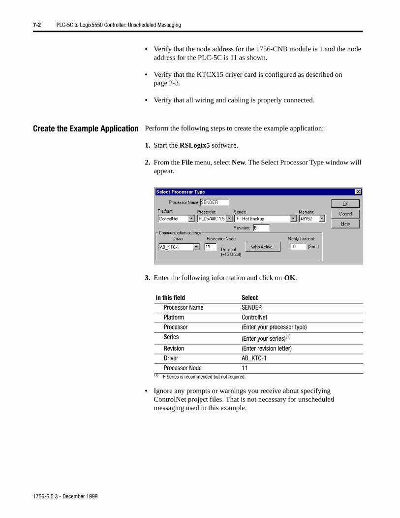
7-2 PLC-5C to Logix5550 Controller: Unscheduled Messaging
• Verify that the node address for the 1756-CNB module is 1 and the node address for the PLC-5C is 11 as shown.
• Verify that the KTCX15 driver card is configured as described on page 2-3.
• Verify that all wiring and cabling is properly connected.
Create the Example Application Perform the following steps to create the example application:
1. Start the RSLogix5 software.
2. From the File menu, select New. The Select Processor Type window will appear.
3. Enter the following information and click on OK.
• Ignore any prompts or warnings you receive about specifying ControlNet project files. That is not necessary for unscheduled messaging used in this example.
In this field Select
Processor Name SENDER
Platform ControlNet
Processor (Enter your processor type)
Series (Enter your series)(1)
(1) F Series is recommended but not required.
Revision (Enter revision letter)
Driver AB_KTC-1
Processor Node 11
1756-6.5.3 - December 1999
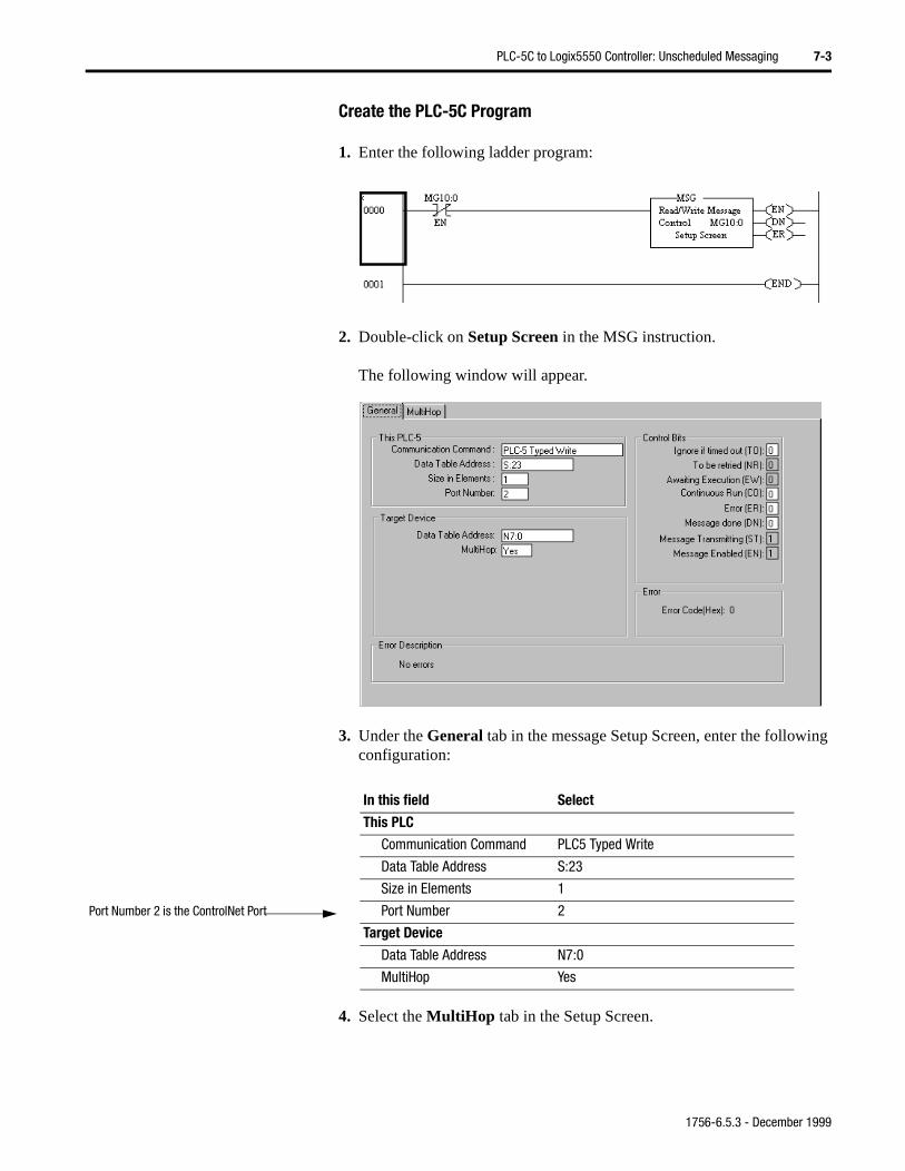
PLC-5C to Logix5550 Controller: Unscheduled Messaging 7-3
Create the PLC-5C Program
1. Enter the following ladder program:
2. Double-click on Setup Screen in the MSG instruction.
The following window will appear.
3. Under the General tab in the message Setup Screen, enter the following configuration:
4. Select the MultiHop tab in the Setup Screen.
In this field Select
This PLC
Communication Command PLC5 Typed Write
Data Table Address S:23
Size in Elements 1
Port Number 2
Target Device
Data Table Address N7:0
MultiHop Yes
Port Number 2 is the ControlNet Port
1756-6.5.3 - December 1999
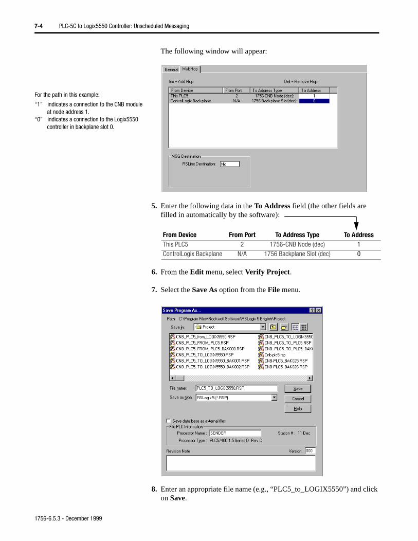
7-4 PLC-5C to Logix5550 Controller: Unscheduled Messaging
ck
The following window will appear:
5. Enter the following data in the To Address field (the other fields are filled in automatically by the software):
6. From the Edit menu, select Verify Project.
7. Select the Save As option from the File menu.
8. Enter an appropriate file name (e.g., “PLC5_to_LOGIX5550”) and clion Save.
For the path in this example:
“1” indicates a connection to the CNB module at node address 1.
“0” indicates a connection to the Logix5550 controller in backplane slot 0.
From Device From Port To Address Type To AddressThis PLC5 2 1756-CNB Node (dec) 1ControlLogix Backplane N/A 1756 Backplane Slot (dec) 0
1756-6.5.3 - December 1999
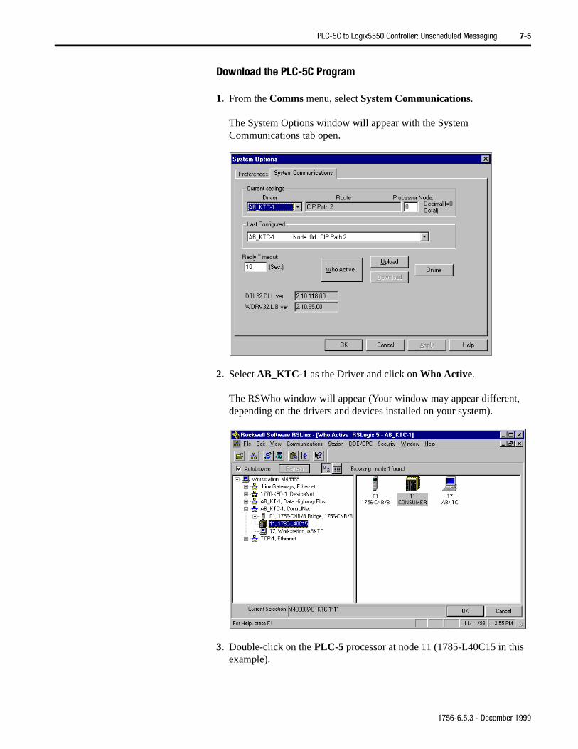
PLC-5C to Logix5550 Controller: Unscheduled Messaging 7-5
Download the PLC-5C Program
1. From the Comms menu, select System Communications.
The System Options window will appear with the System Communications tab open.
2. Select AB_KTC-1 as the Driver and click on Who Active.
The RSWho window will appear (Your window may appear different, depending on the drivers and devices installed on your system).
3. Double-click on the PLC-5 processor at node 11 (1785-L40C15 in this example).
1756-6.5.3 - December 1999
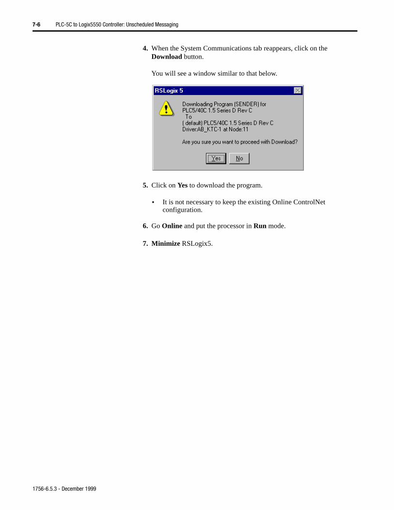
7-6 PLC-5C to Logix5550 Controller: Unscheduled Messaging
4. When the System Communications tab reappears, click on the Download button.
You will see a window similar to that below.
5. Click on Yes to download the program.
• It is not necessary to keep the existing Online ControlNet configuration.
6. Go Online and put the processor in Run mode.
7. Minimize RSLogix5.
1756-6.5.3 - December 1999
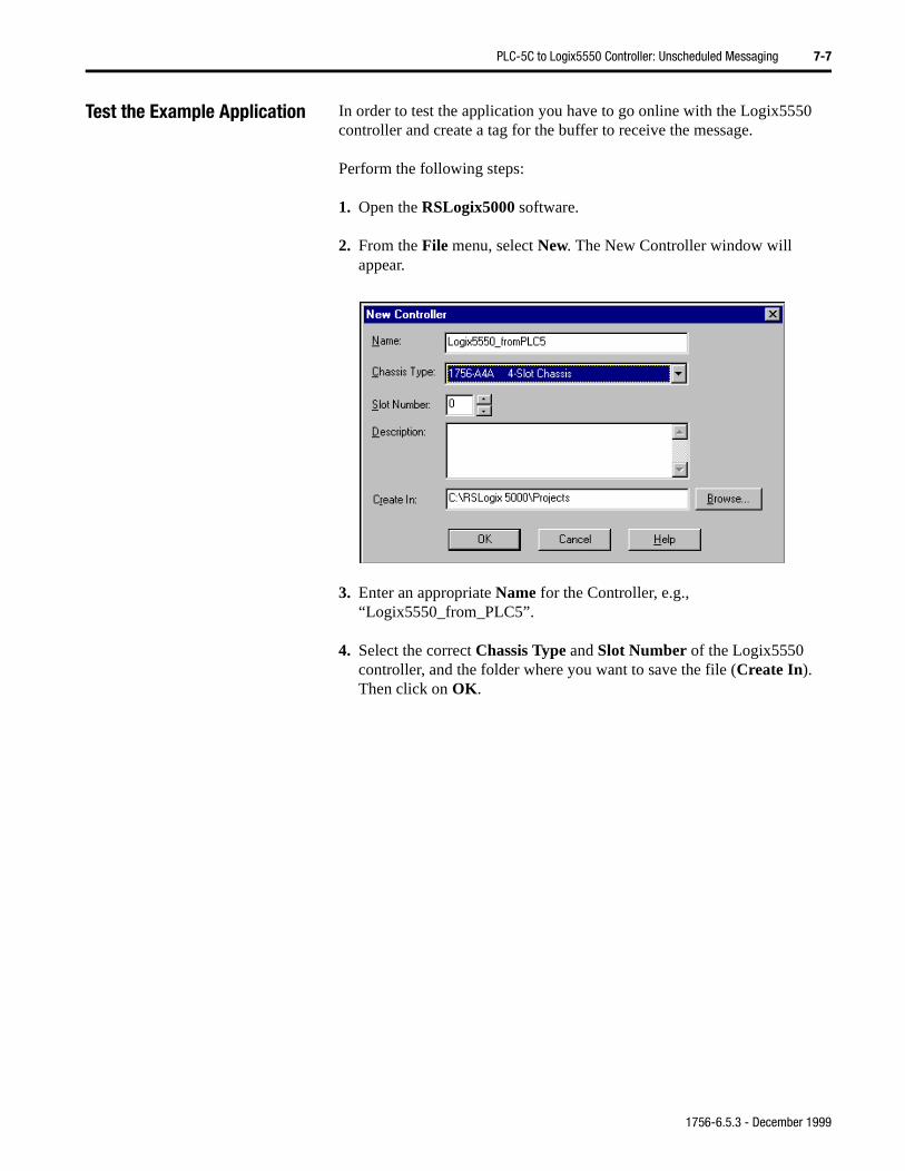
PLC-5C to Logix5550 Controller: Unscheduled Messaging 7-7
Test the Example Application In order to test the application you have to go online with the Logix5550 controller and create a tag for the buffer to receive the message.
Perform the following steps:
1. Open the RSLogix5000 software.
2. From the File menu, select New. The New Controller window will appear.
3. Enter an appropriate Name for the Controller, e.g., “Logix5550_from_PLC5”.
4. Select the correct Chassis Type and Slot Number of the Logix5550 controller, and the folder where you want to save the file (Create In). Then click on OK.
1756-6.5.3 - December 1999
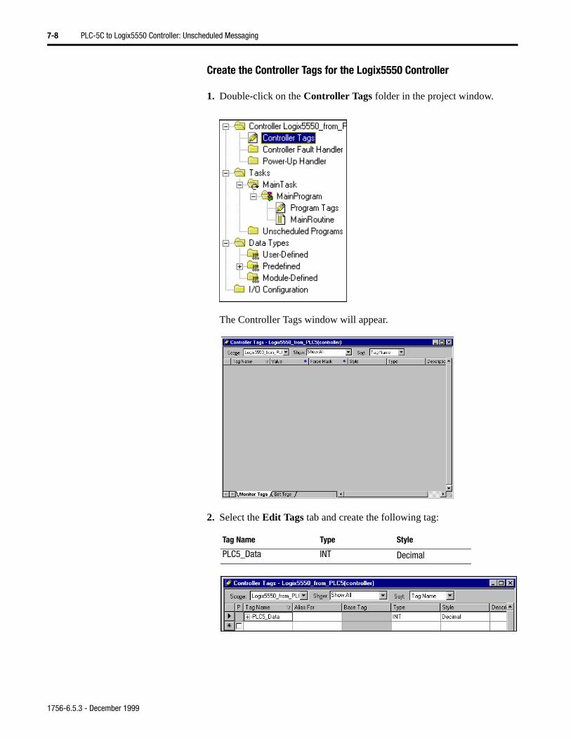
7-8 PLC-5C to Logix5550 Controller: Unscheduled Messaging
Create the Controller Tags for the Logix5550 Controller
1. Double-click on the Controller Tags folder in the project window.
The Controller Tags window will appear.
2. Select the Edit Tags tab and create the following tag:
Tag Name Type Style
PLC5_Data INT Decimal
1756-6.5.3 - December 1999
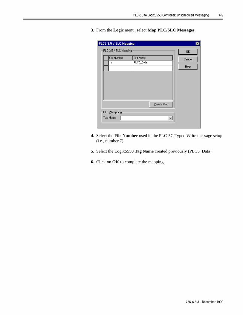
PLC-5C to Logix5550 Controller: Unscheduled Messaging 7-9
3. From the Logic menu, select Map PLC/SLC Messages.
4. Select the File Number used in the PLC-5C Typed Write message setup (i.e., number 7).
5. Select the Logix5550 Tag Name created previously (PLC5_Data).
6. Click on OK to complete the mapping.
1756-6.5.3 - December 1999
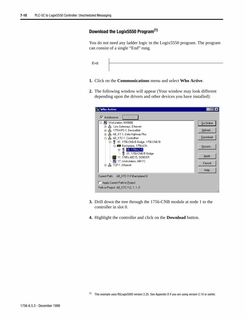
7-10 PLC-5C to Logix5550 Controller: Unscheduled Messaging
Download the Logix5550 Program(1)
You do not need any ladder logic in the Logix5550 program. The program can consist of a single “End” rung.
1. Click on the Communications menu and select Who Active.
2. The following window will appear (Your window may look different depending upon the drivers and other devices you have installed):
3. Drill down the tree through the 1756-CNB module at node 1 to the controller in slot 0.
4. Highlight the controller and click on the Download button.
(1) This example uses RSLogix5000 version 2.25. See Appendix D if you are using version 2.10 or earlier.
1756-6.5.3 - December 1999
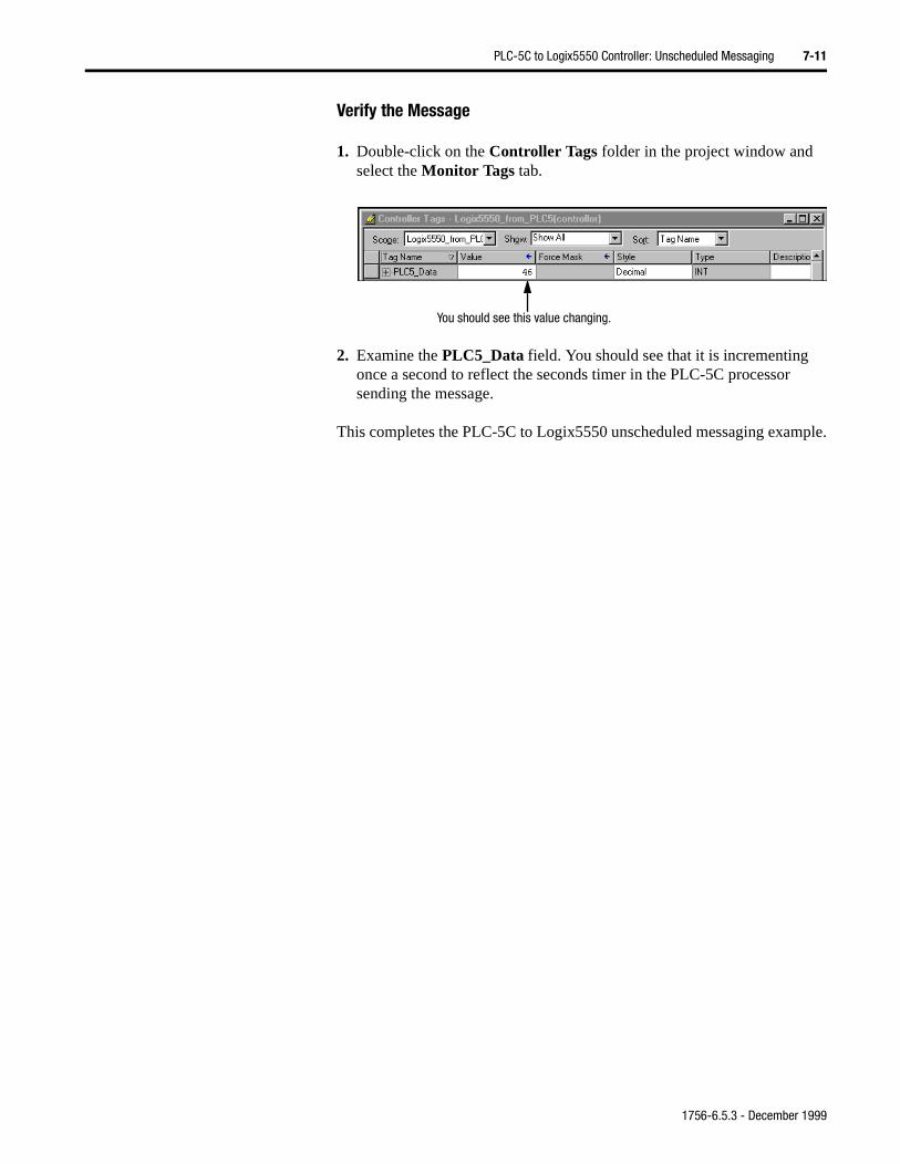
PLC-5C to Logix5550 Controller: Unscheduled Messaging 7-11
Verify the Message
1. Double-click on the Controller Tags folder in the project window and select the Monitor Tags tab.
2. Examine the PLC5_Data field. You should see that it is incrementing once a second to reflect the seconds timer in the PLC-5C processor sending the message.
This completes the PLC-5C to Logix5550 unscheduled messaging example.
You should see this value changing.
1756-6.5.3 - December 1999

7-12 PLC-5C to Logix5550 Controller: Unscheduled Messaging
1756-6.5.3 - December 1999
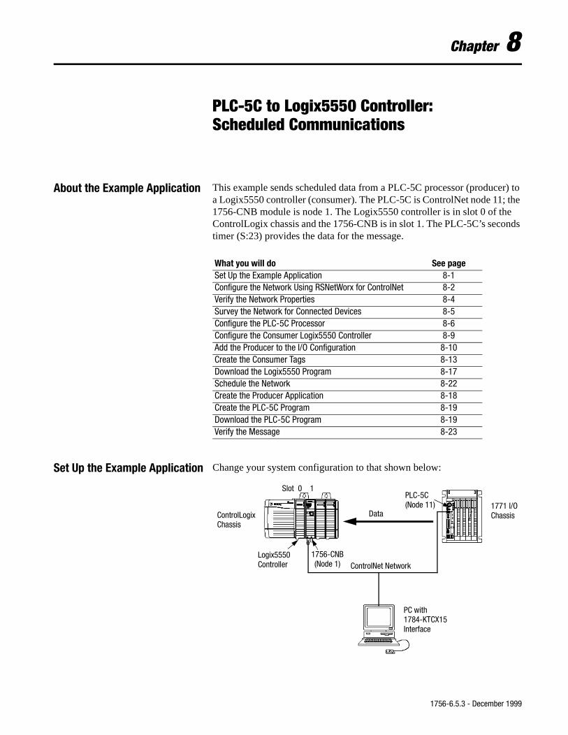
nds
Chapter 8
PLC-5C to Logix5550 Controller:Scheduled Communications
About the Example Application This example sends scheduled data from a PLC-5C processor (producer) to a Logix5550 controller (consumer). The PLC-5C is ControlNet node 11; the 1756-CNB module is node 1. The Logix5550 controller is in slot 0 of the ControlLogix chassis and the 1756-CNB is in slot 1. The PLC-5C’s secotimer (S:23) provides the data for the message.
Set Up the Example Application Change your system configuration to that shown below:
What you will do See pageSet Up the Example Application 8-1Configure the Network Using RSNetWorx for ControlNet 8-2Verify the Network Properties 8-4Survey the Network for Connected Devices 8-5Configure the PLC-5C Processor 8-6Configure the Consumer Logix5550 Controller 8-9Add the Producer to the I/O Configuration 8-10Create the Consumer Tags 8-13Download the Logix5550 Program 8-17Schedule the Network 8-22Create the Producer Application 8-18Create the PLC-5C Program 8-19Download the PLC-5C Program 8-19Verify the Message 8-23
ControlNet NetworkLogix5550 1756-CNB
(Node 1)
PLC-5C
ControlLogixChassis
1771 I/OChassis
PC with1784-KTCX15Interface
Data
Slot 0 1
(Node 11)
Controller
1756-6.5.3 - December 1999
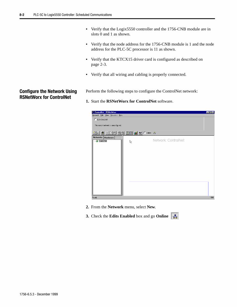
8-2 PLC-5C to Logix5550 Controller: Scheduled Communications
• Verify that the Logix5550 controller and the 1756-CNB module are in slots 0 and 1 as shown.
• Verify that the node address for the 1756-CNB module is 1 and the node address for the PLC-5C processor is 11 as shown.
• Verify that the KTCX15 driver card is configured as described on page 2-3.
• Verify that all wiring and cabling is properly connected.
Configure the Network Using RSNetWorx for ControlNet
Perform the following steps to configure the ControlNet network:
1. Start the RSNetWorx for ControlNet software.
2. From the Network menu, select New.
3. Check the Edits Enabled box and go Online
1756-6.5.3 - December 1999
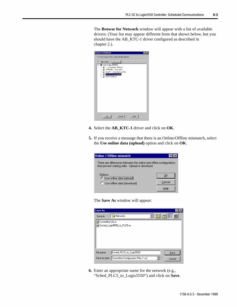
PLC-5C to Logix5550 Controller: Scheduled Communications 8-3
The Browse for Network window will appear with a list of available drivers. (Your list may appear different from that shown below, but you should have the AB_KTC-1 driver configured as described in chapter 2.).
4. Select the AB_KTC-1 driver and click on OK.
5. If you receive a message that there is an Online/Offline mismatch, select the Use online data (upload) option and click on OK.
The Save As window will appear:
6. Enter an appropriate name for the network (e.g., “Sched_PLC5_to_Logix5550”) and click on Save.
1756-6.5.3 - December 1999
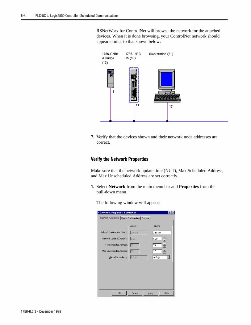
8-4 PLC-5C to Logix5550 Controller: Scheduled Communications
RSNetWorx for ControlNet will browse the network for the attached devices. When it is done browsing, your ControlNet network should appear similar to that shown below:
7. Verify that the devices shown and their network node addresses are correct.
Verify the Network Properties
Make sure that the network update time (NUT), Max Scheduled Address, and Max Unscheduled Address are set correctly.
1. Select Network from the main menu bar and Properties from the pull-down menu.
The following window will appear:
1756-6.5.3 - December 1999
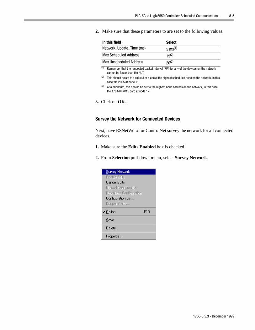
PLC-5C to Logix5550 Controller: Scheduled Communications 8-5
2. Make sure that these parameters to are set to the following values:
3. Click on OK.
Survey the Network for Connected Devices
Next, have RSNetWorx for ControlNet survey the network for all connected devices.
1. Make sure the Edits Enabled box is checked.
2. From Selection pull-down menu, select Survey Network.
In this field SelectNetwork_Update_Time (ms) 5 ms(1)
(1) Remember that the requested packet interval (RPI) for any of the devices on the network cannot be faster than the NUT.
Max Scheduled Address 15(2)
(2) This should be set to a value 3 or 4 above the highest scheduled node on the network, in this case the PLC5 at node 11.
Max Unscheduled Address 20(3)
(3) At a minimum, this should be set to the highest node address on the network, in this case the 1784-KTXC15 card at node 17.
1756-6.5.3 - December 1999
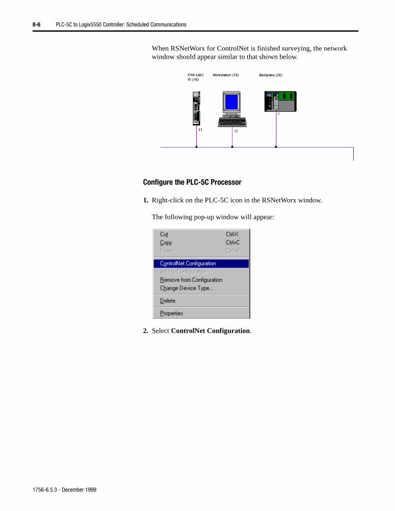
8-6 PLC-5C to Logix5550 Controller: Scheduled Communications
When RSNetWorx for ControlNet is finished surveying, the network window should appear similar to that shown below.
Configure the PLC-5C Processor
1. Right-click on the PLC-5C icon in the RSNetWorx window.
The following pop-up window will appear:
2. Select ControlNet Configuration.
1756-6.5.3 - December 1999
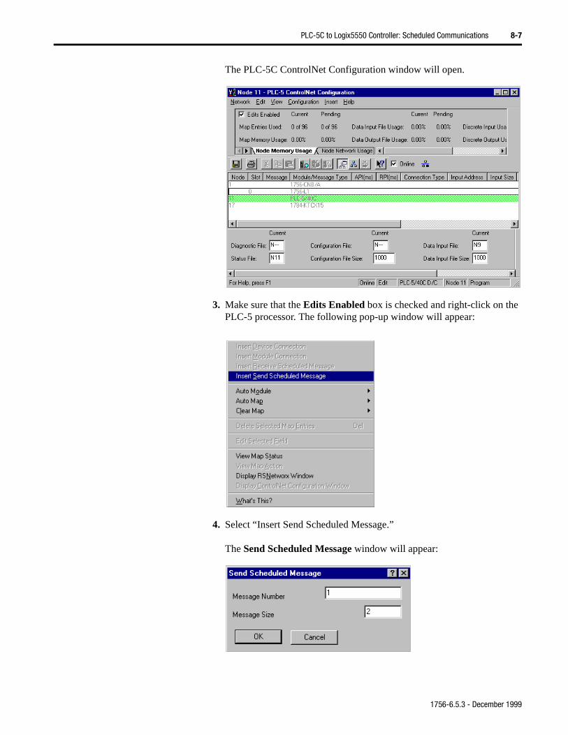
PLC-5C to Logix5550 Controller: Scheduled Communications 8-7
The PLC-5C ControlNet Configuration window will open.
3. Make sure that the Edits Enabled box is checked and right-click on the PLC-5 processor. The following pop-up window will appear:
4. Select “Insert Send Scheduled Message.”
The Send Scheduled Message window will appear:
1756-6.5.3 - December 1999
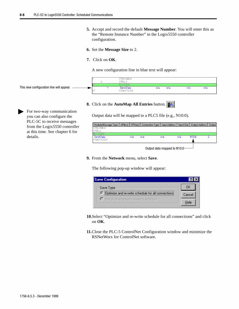
8-8 PLC-5C to Logix5550 Controller: Scheduled Communications
5. Accept and record the default Message Number. You will enter this as the “Remote Instance Number” in the Logix5550 controller configuration.
6. Set the Message Size to 2.
7. Click on OK.
A new configuration line in blue text will appear:
8. Click on the AutoMap All Entries button.
Output data will be mapped to a PLC5 file (e.g., N10:0).
9. From the Network menu, select Save.
The following pop-up window will appear:
10.Select “Optimize and re-write schedule for all connections” and clickon OK.
11.Close the PLC-5 ControlNet Configuration window and minimize theRSNetWorx for ControlNet software.
This new configuration line will appear.
For two-way communication you can also configure the PLC-5C to receive messages from the Logix5550 controller at this time. See chapter 6 for details.
Output data mapped to N10:0
1756-6.5.3 - December 1999
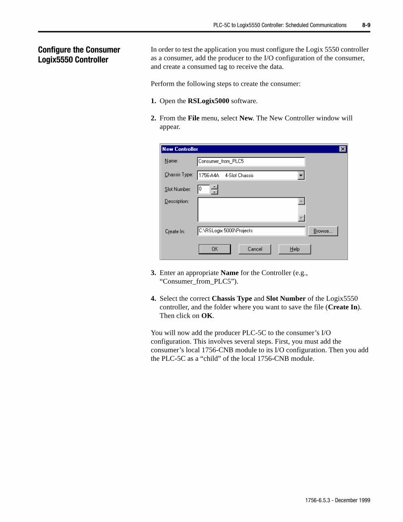
PLC-5C to Logix5550 Controller: Scheduled Communications 8-9
dd
Configure the Consumer Logix5550 Controller
In order to test the application you must configure the Logix 5550 controller as a consumer, add the producer to the I/O configuration of the consumer, and create a consumed tag to receive the data.
Perform the following steps to create the consumer:
1. Open the RSLogix5000 software.
2. From the File menu, select New. The New Controller window will appear.
3. Enter an appropriate Name for the Controller (e.g., “Consumer_from_PLC5”).
4. Select the correct Chassis Type and Slot Number of the Logix5550 controller, and the folder where you want to save the file (Create In). Then click on OK.
You will now add the producer PLC-5C to the consumer’s I/O configuration. This involves several steps. First, you must add the consumer’s local 1756-CNB module to its I/O configuration. Then you athe PLC-5C as a “child” of the local 1756-CNB module.
1756-6.5.3 - December 1999
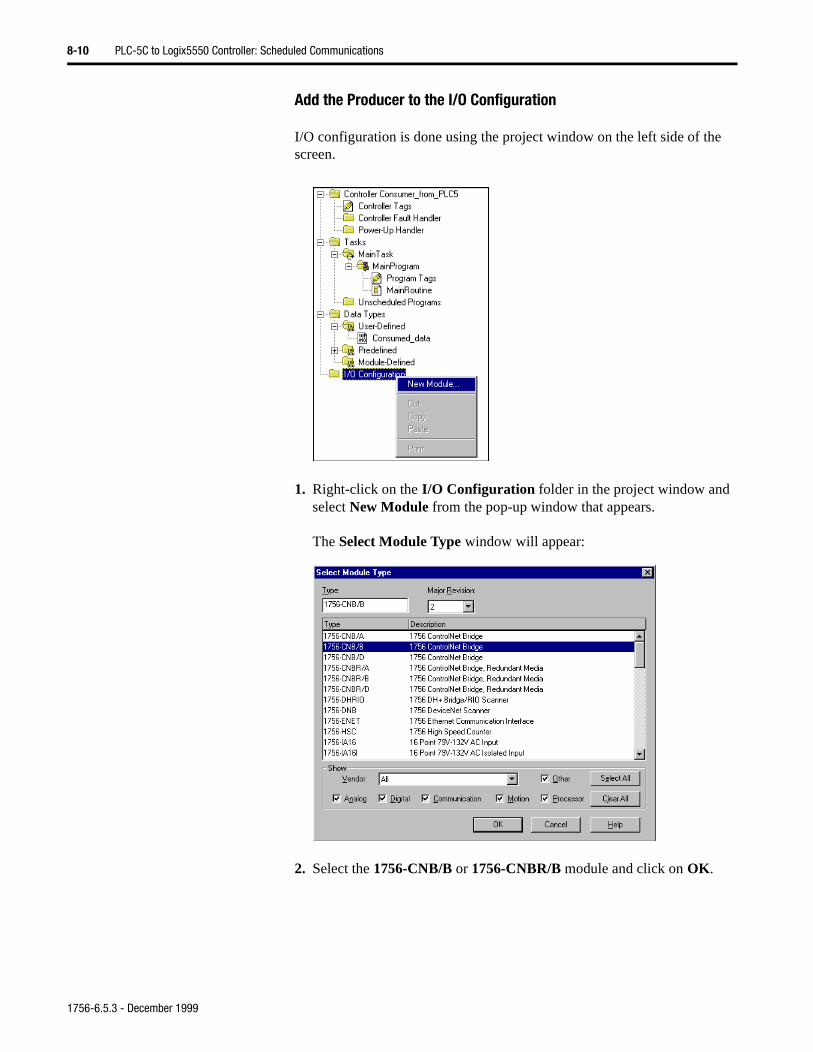
8-10 PLC-5C to Logix5550 Controller: Scheduled Communications
Add the Producer to the I/O Configuration
I/O configuration is done using the project window on the left side of the screen.
1. Right-click on the I/O Configuration folder in the project window and select New Module from the pop-up window that appears.
The Select Module Type window will appear:
2. Select the 1756-CNB/B or 1756-CNBR/B module and click on OK.
1756-6.5.3 - December 1999
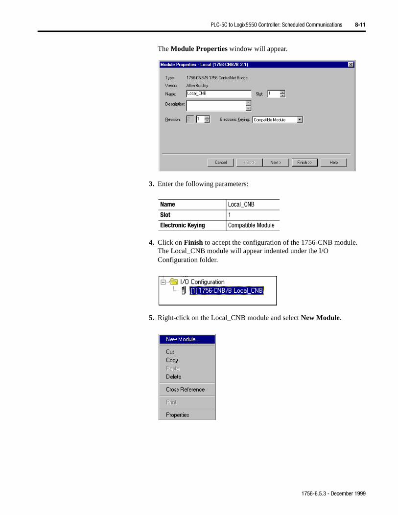
PLC-5C to Logix5550 Controller: Scheduled Communications 8-11
The Module Properties window will appear.
3. Enter the following parameters:
4. Click on Finish to accept the configuration of the 1756-CNB module. The Local_CNB module will appear indented under the I/O Configuration folder.
5. Right-click on the Local_CNB module and select New Module.
Name Local_CNB
Slot 1
Electronic Keying Compatible Module
1756-6.5.3 - December 1999
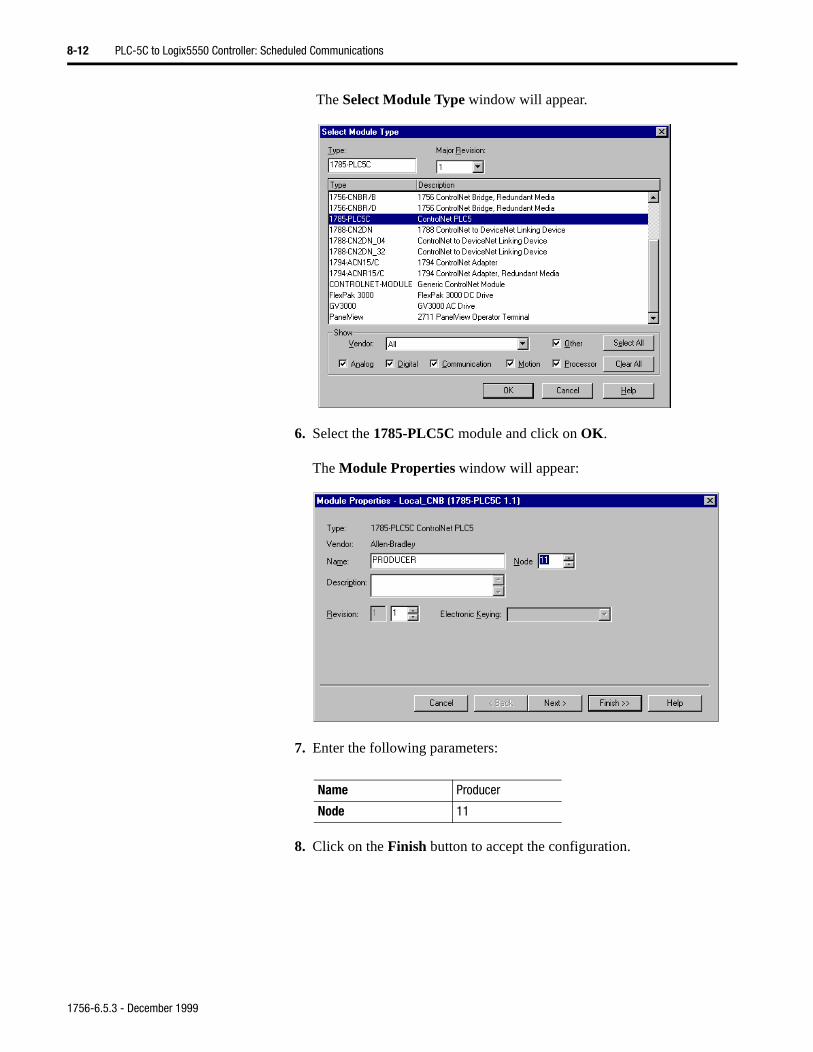
8-12 PLC-5C to Logix5550 Controller: Scheduled Communications
The Select Module Type window will appear.
6. Select the 1785-PLC5C module and click on OK.
The Module Properties window will appear:
7. Enter the following parameters:
8. Click on the Finish button to accept the configuration.
Name Producer
Node 11
1756-6.5.3 - December 1999
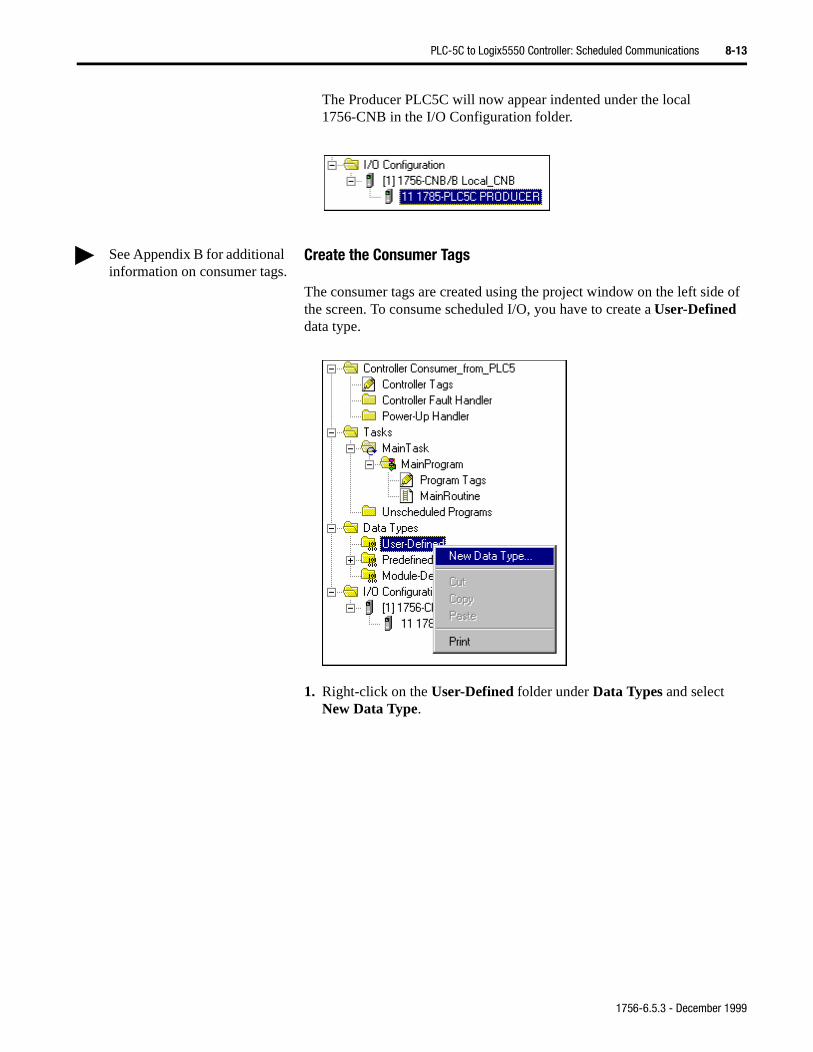
PLC-5C to Logix5550 Controller: Scheduled Communications 8-13
The Producer PLC5C will now appear indented under the local 1756-CNB in the I/O Configuration folder.
Create the Consumer Tags
The consumer tags are created using the project window on the left side of the screen. To consume scheduled I/O, you have to create a User-Defined data type.
1. Right-click on the User-Defined folder under Data Types and select New Data Type.
See Appendix B for additional information on consumer tags.
1756-6.5.3 - December 1999
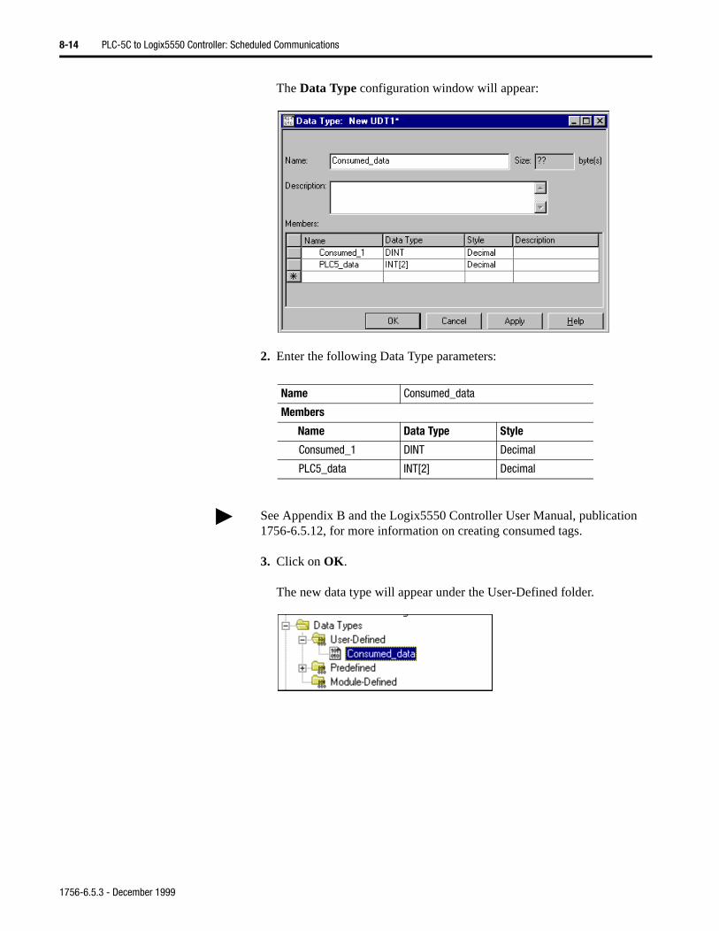
8-14 PLC-5C to Logix5550 Controller: Scheduled Communications
The Data Type configuration window will appear:
2. Enter the following Data Type parameters:
3. Click on OK.
The new data type will appear under the User-Defined folder.
Name Consumed_data
Members
Name Data Type Style
Consumed_1 DINT Decimal
PLC5_data INT[2] Decimal
See Appendix B and the Logix5550 Controller User Manual, publication 1756-6.5.12, for more information on creating consumed tags.
1756-6.5.3 - December 1999
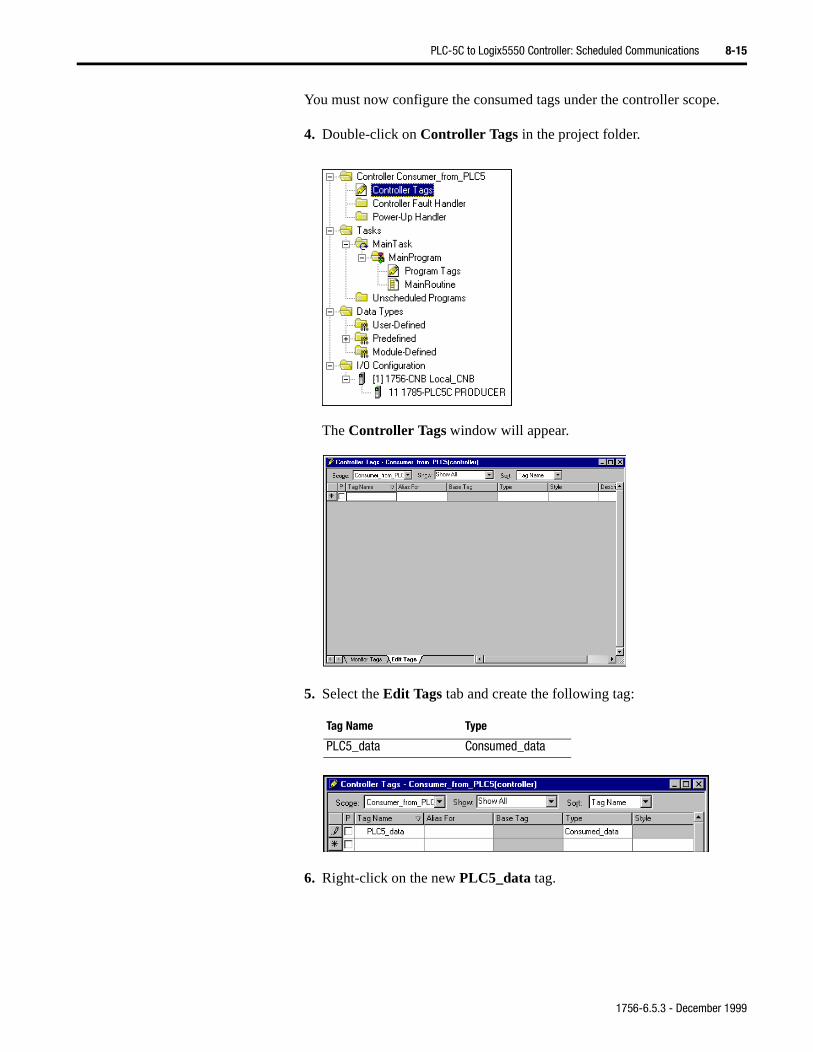
PLC-5C to Logix5550 Controller: Scheduled Communications 8-15
You must now configure the consumed tags under the controller scope.
4. Double-click on Controller Tags in the project folder.
The Controller Tags window will appear.
5. Select the Edit Tags tab and create the following tag:
6. Right-click on the new PLC5_data tag.
Tag Name Type
PLC5_data Consumed_data
1756-6.5.3 - December 1999
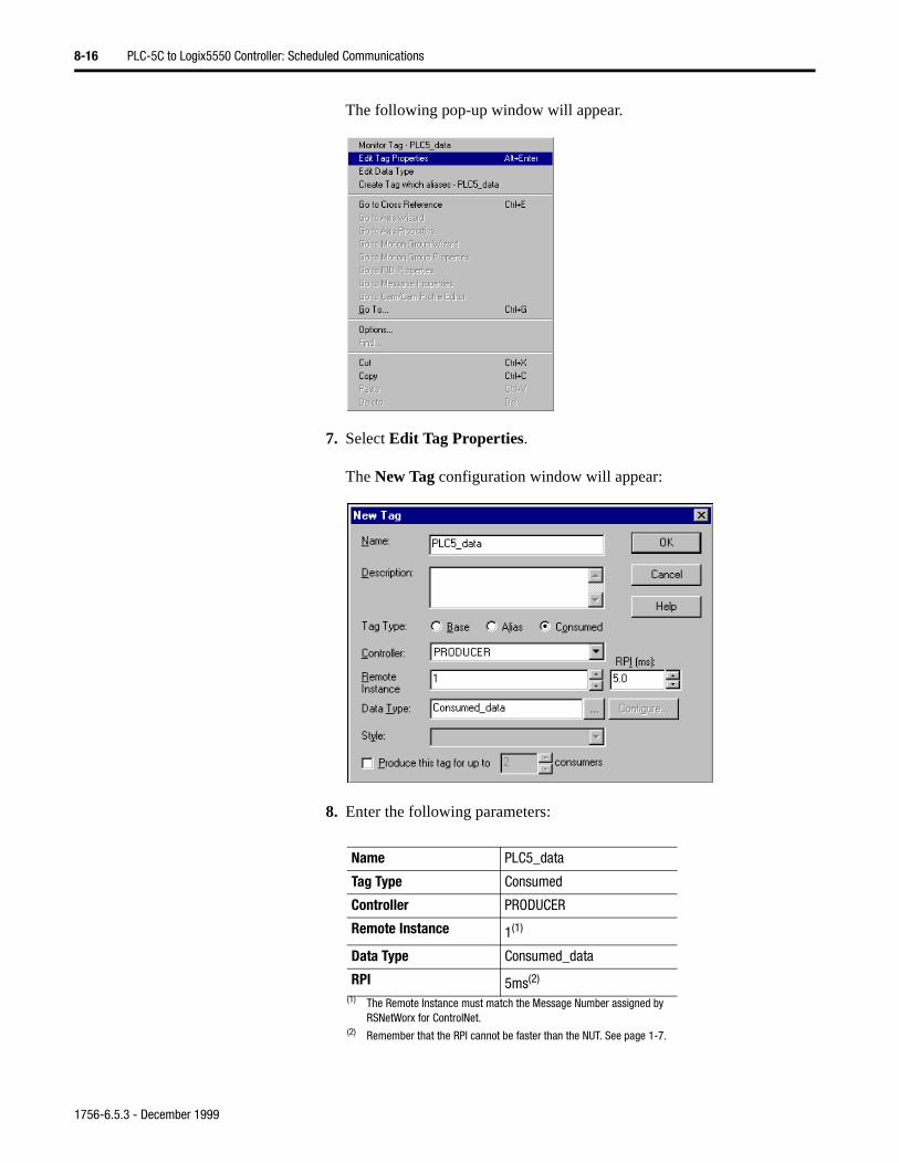
8-16 PLC-5C to Logix5550 Controller: Scheduled Communications
The following pop-up window will appear.
7. Select Edit Tag Properties.
The New Tag configuration window will appear:
8. Enter the following parameters:
Name PLC5_data
Tag Type Consumed
Controller PRODUCER
Remote Instance 1(1)
(1) The Remote Instance must match the Message Number assigned by RSNetWorx for ControlNet.
Data Type Consumed_data
RPI 5ms(2)
(2) Remember that the RPI cannot be faster than the NUT. See page 1-7.
1756-6.5.3 - December 1999
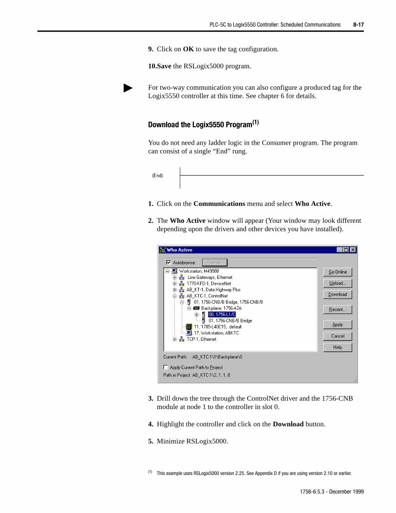
PLC-5C to Logix5550 Controller: Scheduled Communications 8-17
the
9. Click on OK to save the tag configuration.
10.Save the RSLogix5000 program.
Download the Logix5550 Program(1)
You do not need any ladder logic in the Consumer program. The program can consist of a single “End” rung.
1. Click on the Communications menu and select Who Active.
2. The Who Active window will appear (Your window may look different depending upon the drivers and other devices you have installed).
3. Drill down the tree through the ControlNet driver and the 1756-CNB module at node 1 to the controller in slot 0.
4. Highlight the controller and click on the Download button.
5. Minimize RSLogix5000.
For two-way communication you can also configure a produced tag for Logix5550 controller at this time. See chapter 6 for details.
(1) This example uses RSLogix5000 version 2.25. See Appendix D if you are using version 2.10 or earlier.
1756-6.5.3 - December 1999
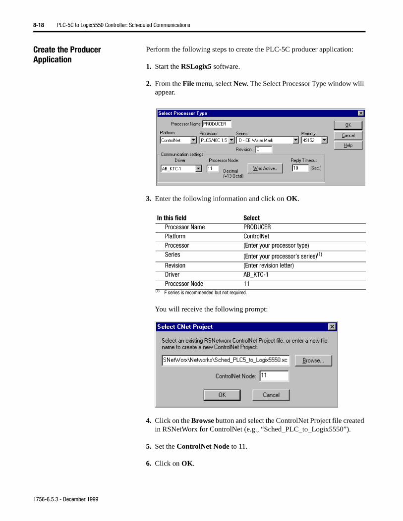
8-18 PLC-5C to Logix5550 Controller: Scheduled Communications
Create the Producer Application
Perform the following steps to create the PLC-5C producer application:
1. Start the RSLogix5 software.
2. From the File menu, select New. The Select Processor Type window will appear.
3. Enter the following information and click on OK.
You will receive the following prompt:
4. Click on the Browse button and select the ControlNet Project file created in RSNetWorx for ControlNet (e.g., “Sched_PLC_to_Logix5550”).
5. Set the ControlNet Node to 11.
6. Click on OK.
In this field SelectProcessor Name PRODUCERPlatform ControlNetProcessor (Enter your processor type)Series (Enter your processor’s series)(1)
(1) F series is recommended but not required.
Revision (Enter revision letter)Driver AB_KTC-1Processor Node 11
1756-6.5.3 - December 1999
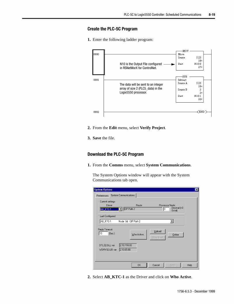
PLC-5C to Logix5550 Controller: Scheduled Communications 8-19
Create the PLC-5C Program
1. Enter the following ladder program:
2. From the Edit menu, select Verify Project.
3. Save the file.
Download the PLC-5C Program
1. From the Comms menu, select System Communications.
The System Options window will appear with the System Communications tab open.
2. Select AB_KTC-1 as the Driver and click on Who Active.
N10 is the Output File configuredin RSNetWorX for ControlNet.
The data will be sent to an integerarray of size 2 (PLC5_data) in theLogix5550 processor.
1756-6.5.3 - December 1999
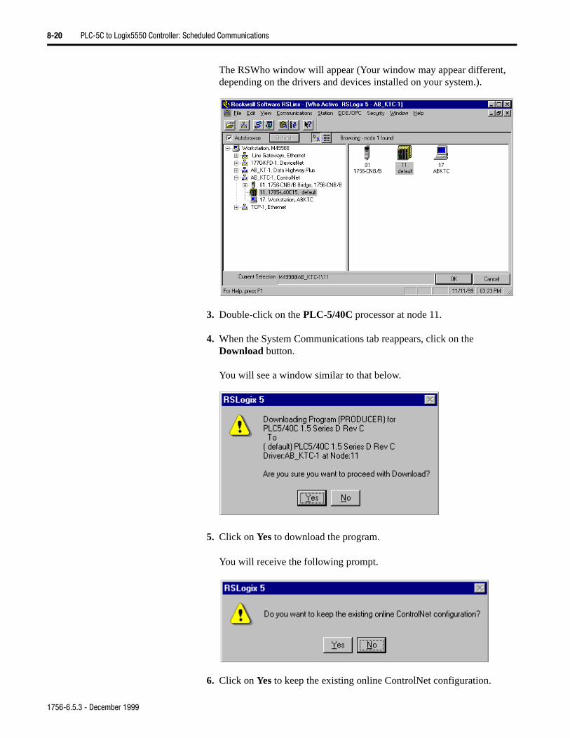
8-20 PLC-5C to Logix5550 Controller: Scheduled Communications
The RSWho window will appear (Your window may appear different, depending on the drivers and devices installed on your system.).
3. Double-click on the PLC-5/40C processor at node 11.
4. When the System Communications tab reappears, click on the Download button.
You will see a window similar to that below.
5. Click on Yes to download the program.
You will receive the following prompt.
6. Click on Yes to keep the existing online ControlNet configuration.
1756-6.5.3 - December 1999
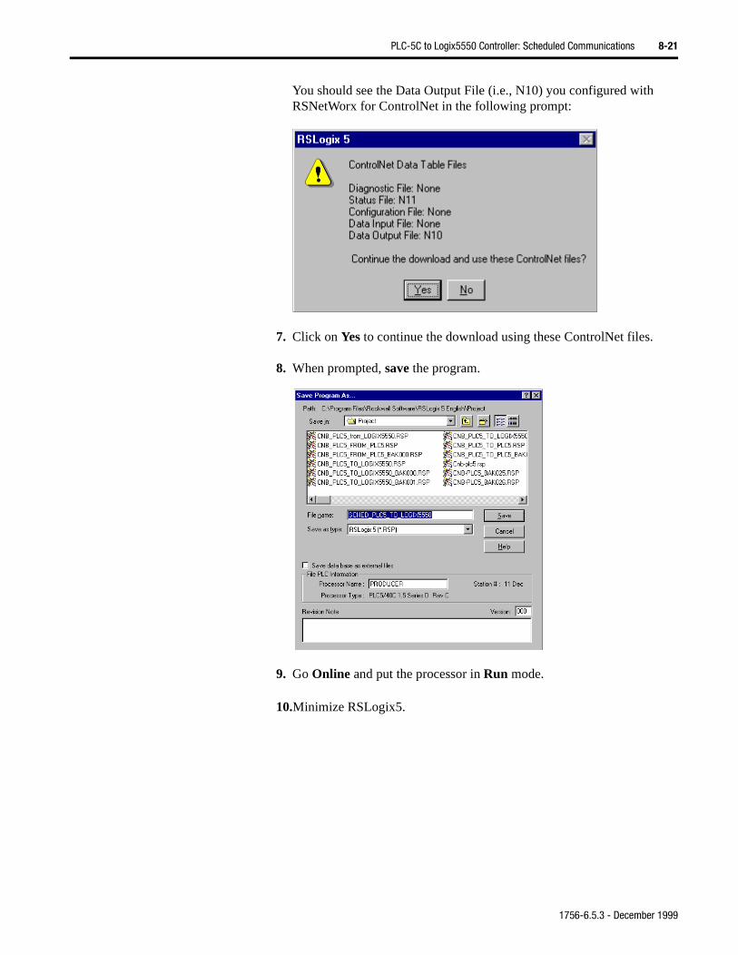
PLC-5C to Logix5550 Controller: Scheduled Communications 8-21
You should see the Data Output File (i.e., N10) you configured with RSNetWorx for ControlNet in the following prompt:
7. Click on Yes to continue the download using these ControlNet files.
8. When prompted, save the program.
9. Go Online and put the processor in Run mode.
10.Minimize RSLogix5.
1756-6.5.3 - December 1999
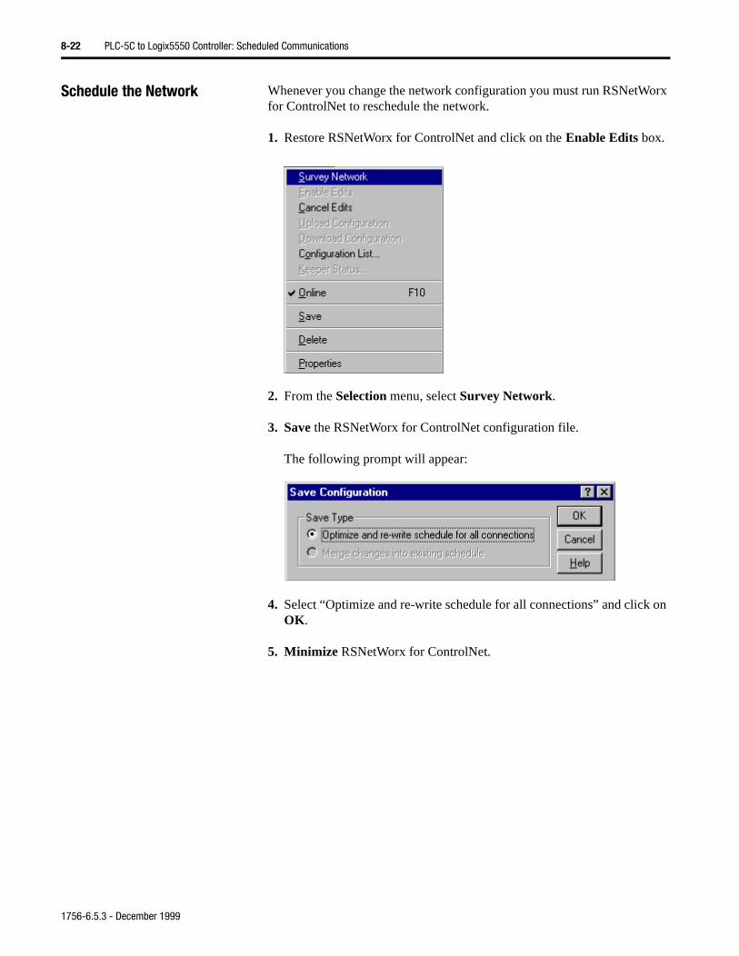
8-22 PLC-5C to Logix5550 Controller: Scheduled Communications
on
Schedule the Network Whenever you change the network configuration you must run RSNetWorx for ControlNet to reschedule the network.
1. Restore RSNetWorx for ControlNet and click on the Enable Edits box.
2. From the Selection menu, select Survey Network.
3. Save the RSNetWorx for ControlNet configuration file.
The following prompt will appear:
4. Select “Optimize and re-write schedule for all connections” and click OK.
5. Minimize RSNetWorx for ControlNet.
1756-6.5.3 - December 1999
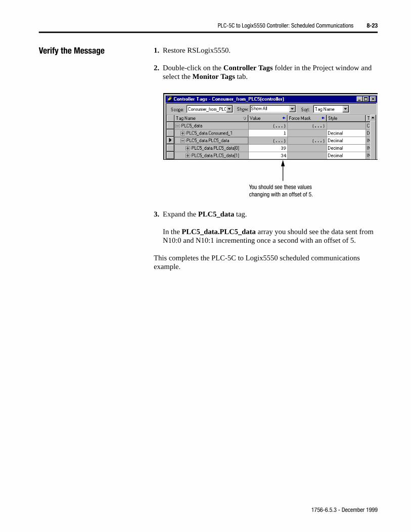
PLC-5C to Logix5550 Controller: Scheduled Communications 8-23
Verify the Message 1. Restore RSLogix5550.
2. Double-click on the Controller Tags folder in the Project window and select the Monitor Tags tab.
3. Expand the PLC5_data tag.
In the PLC5_data.PLC5_data array you should see the data sent from N10:0 and N10:1 incrementing once a second with an offset of 5.
This completes the PLC-5C to Logix5550 scheduled communications example.
You should see these valueschanging with an offset of 5.
1756-6.5.3 - December 1999

8-24 PLC-5C to Logix5550 Controller: Scheduled Communications
1756-6.5.3 - December 1999
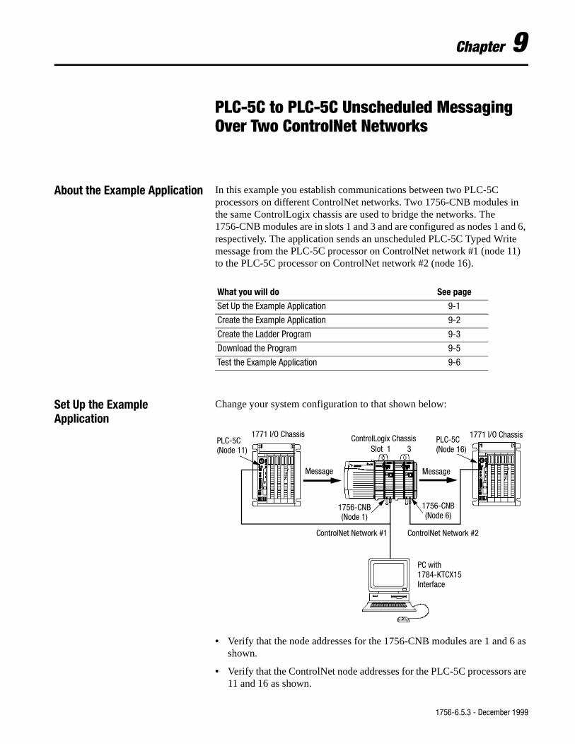
Chapter 9
PLC-5C to PLC-5C Unscheduled Messaging Over Two ControlNet Networks
About the Example Application In this example you establish communications between two PLC-5C processors on different ControlNet networks. Two 1756-CNB modules in the same ControlLogix chassis are used to bridge the networks. The 1756-CNB modules are in slots 1 and 3 and are configured as nodes 1 and 6, respectively. The application sends an unscheduled PLC-5C Typed Write message from the PLC-5C processor on ControlNet network #1 (node 11) to the PLC-5C processor on ControlNet network #2 (node 16).
Set Up the ExampleApplication
Change your system configuration to that shown below:
• Verify that the node addresses for the 1756-CNB modules are 1 and 6 as shown.
• Verify that the ControlNet node addresses for the PLC-5C processors are 11 and 16 as shown.
What you will do See page
Set Up the Example Application 9-1
Create the Example Application 9-2
Create the Ladder Program 9-3
Download the Program 9-5
Test the Example Application 9-6
ControlNet Network #1
1756-CNB(Node 1)
PLC-5C ControlLogix Chassis
PC with1784-KTCX15Interface
Message
Slot 1 3(Node 11)
1756-CNB(Node 6)
PLC-5C(Node 16)
Message
ControlNet Network #2
1771 I/O Chassis 1771 I/O Chassis
1756-6.5.3 - December 1999
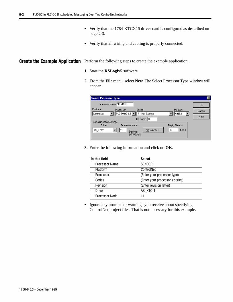
9-2 PLC-5C to PLC-5C Unscheduled Messaging Over Two ControlNet Networks
• Verify that the 1784-KTCX15 driver card is configured as described on page 2-3.
• Verify that all wiring and cabling is properly connected.
Create the Example Application Perform the following steps to create the example application:
1. Start the RSLogix5 software
2. From the File menu, select New. The Select Processor Type window will appear.
3. Enter the following information and click on OK.
• Ignore any prompts or warnings you receive about specifying ControlNet project files. That is not necessary for this example.
In this field SelectProcessor Name SENDERPlatform ControlNetProcessor (Enter your processor type)Series (Enter your processor’s series)Revision (Enter revision letter)Driver AB_KTC-1Processor Node 11
1756-6.5.3 - December 1999
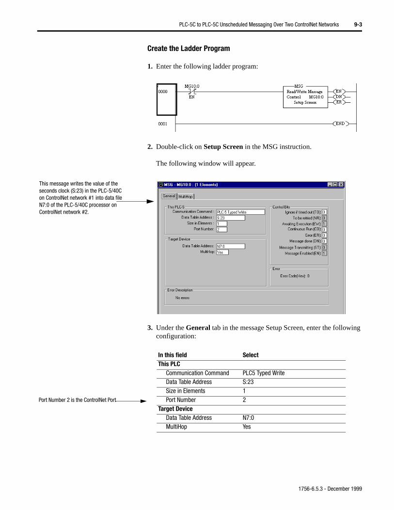
PLC-5C to PLC-5C Unscheduled Messaging Over Two ControlNet Networks 9-3
Create the Ladder Program
1. Enter the following ladder program:
2. Double-click on Setup Screen in the MSG instruction.
The following window will appear.
3. Under the General tab in the message Setup Screen, enter the following configuration:
This message writes the value of the seconds clock (S:23) in the PLC-5/40C on ControlNet network #1 into data file N7:0 of the PLC-5/40C processor on ControlNet network #2.
In this field SelectThis PLC
Communication Command PLC5 Typed WriteData Table Address S:23Size in Elements 1Port Number 2
Target DeviceData Table Address N7:0MultiHop Yes
Port Number 2 is the ControlNet Port
1756-6.5.3 - December 1999
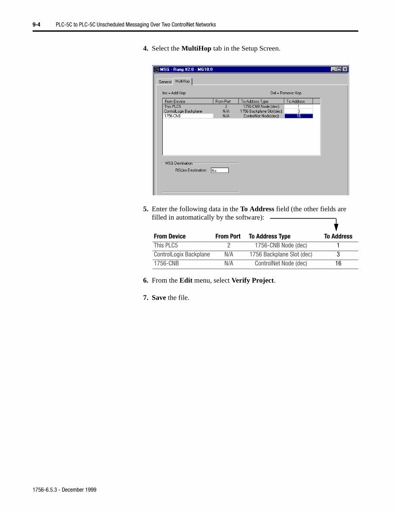
9-4 PLC-5C to PLC-5C Unscheduled Messaging Over Two ControlNet Networks
4. Select the MultiHop tab in the Setup Screen.
5. Enter the following data in the To Address field (the other fields are filled in automatically by the software):
6. From the Edit menu, select Verify Project.
7. Save the file.
From Device From Port To Address Type To AddressThis PLC5 2 1756-CNB Node (dec) 1ControlLogix Backplane N/A 1756 Backplane Slot (dec) 31756-CNB N/A ControlNet Node (dec) 16
1756-6.5.3 - December 1999
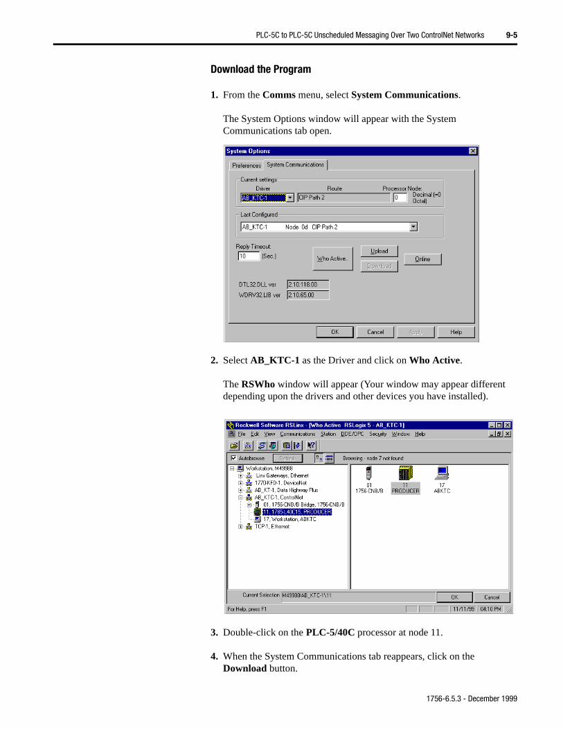
PLC-5C to PLC-5C Unscheduled Messaging Over Two ControlNet Networks 9-5
Download the Program
1. From the Comms menu, select System Communications.
The System Options window will appear with the System Communications tab open.
2. Select AB_KTC-1 as the Driver and click on Who Active.
The RSWho window will appear (Your window may appear different depending upon the drivers and other devices you have installed).
3. Double-click on the PLC-5/40C processor at node 11.
4. When the System Communications tab reappears, click on the Download button.
1756-6.5.3 - December 1999
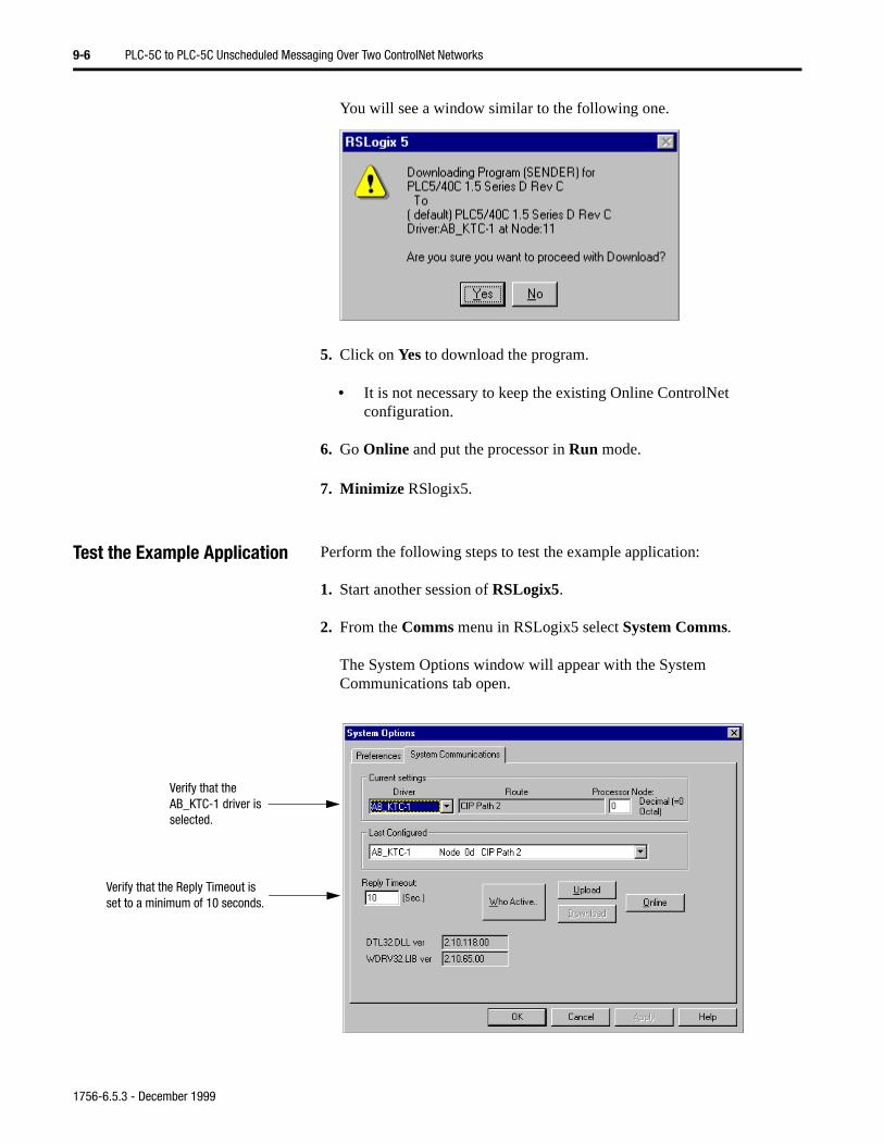
9-6 PLC-5C to PLC-5C Unscheduled Messaging Over Two ControlNet Networks
You will see a window similar to the following one.
5. Click on Yes to download the program.
• It is not necessary to keep the existing Online ControlNet configuration.
6. Go Online and put the processor in Run mode.
7. Minimize RSlogix5.
Test the Example Application Perform the following steps to test the example application:
1. Start another session of RSLogix5.
2. From the Comms menu in RSLogix5 select System Comms.
The System Options window will appear with the System Communications tab open.
Verify that the AB_KTC-1 driver is selected.
Verify that the Reply Timeout is set to a minimum of 10 seconds.
1756-6.5.3 - December 1999
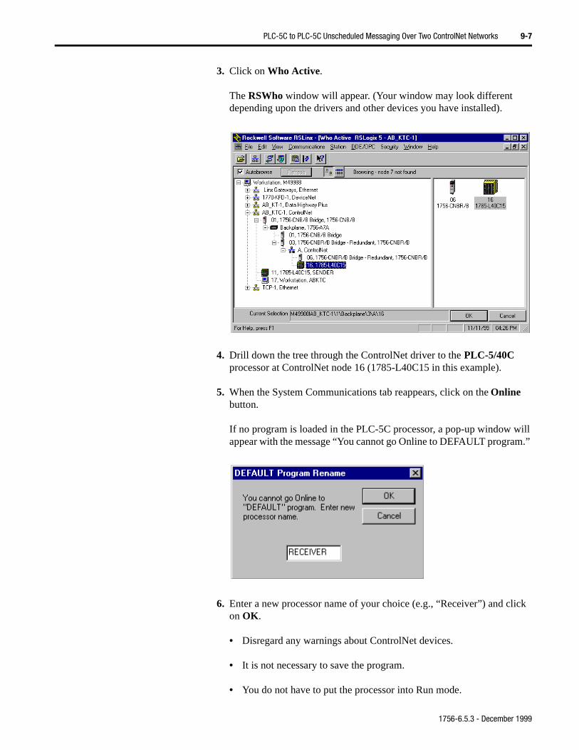
PLC-5C to PLC-5C Unscheduled Messaging Over Two ControlNet Networks 9-7
.”
ick
3. Click on Who Active.
The RSWho window will appear. (Your window may look different depending upon the drivers and other devices you have installed).
4. Drill down the tree through the ControlNet driver to the PLC-5/40C processor at ControlNet node 16 (1785-L40C15 in this example).
5. When the System Communications tab reappears, click on the Online button.
If no program is loaded in the PLC-5C processor, a pop-up window will appear with the message “You cannot go Online to DEFAULT program
6. Enter a new processor name of your choice (e.g., “Receiver”) and clon OK.
• Disregard any warnings about ControlNet devices.
• It is not necessary to save the program.
• You do not have to put the processor into Run mode.
1756-6.5.3 - December 1999
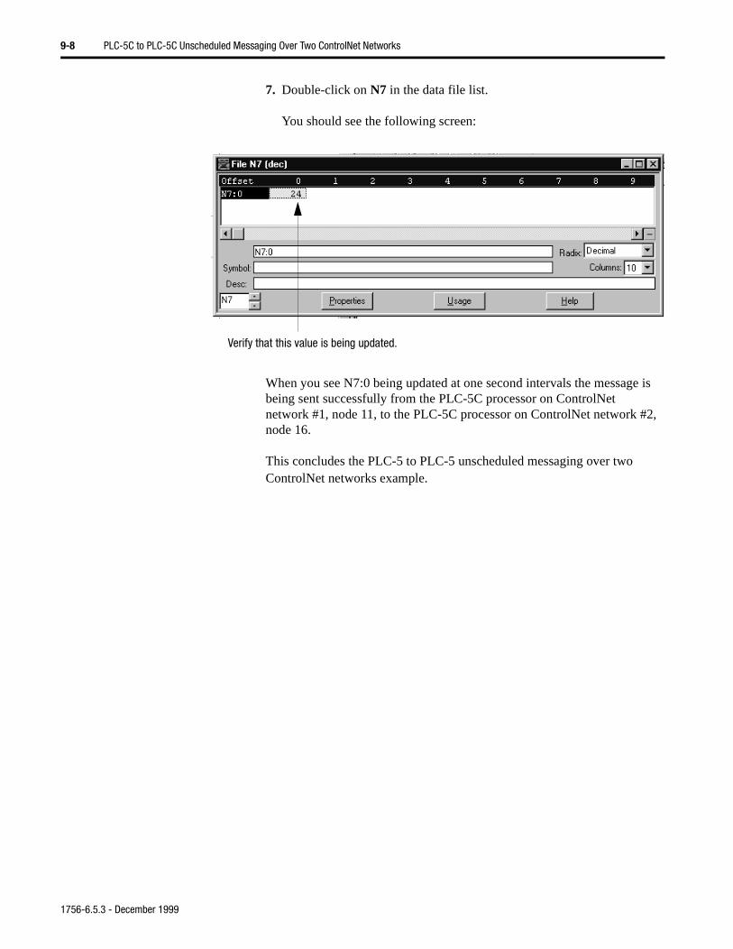
9-8 PLC-5C to PLC-5C Unscheduled Messaging Over Two ControlNet Networks
7. Double-click on N7 in the data file list.
You should see the following screen:
When you see N7:0 being updated at one second intervals the message is being sent successfully from the PLC-5C processor on ControlNet network #1, node 11, to the PLC-5C processor on ControlNet network #2, node 16.
This concludes the PLC-5 to PLC-5 unscheduled messaging over two ControlNet networks example.
Verify that this value is being updated.
1756-6.5.3 - December 1999
e e 6) ne
and
Chapter 10
Controlling I/O Over a ControlNet Network
About the Example Application This example application uses scheduled communications to read data from a remote digital input module and send data to a remote digital output module. The example simulates a parts counter operation.
The local ControlLogix chassis contains the Logix5550 controller in slot 0 and the “parent” 1756-CNB module (configured as node 1) in slot 1. Thremote chassis contains a “child” 1756-CNB module (configured as nodin slot 1 and the I/O modules in slots 2 and 3. Network scheduling is dousing RSNetworx for ControlNet software.
The basic procedure given in this example can also be used to configureschedule FLEX I/O on a ControlNet network.
What you will do See page
Set Up the Example Application 10-2
Create the Example Application 10-2
Add the Local CNB Module to the I/O Configuration 10-3
Add the Remote CNB Module to the I/O Configuration 10-4
Add the Remote I/O Modules to the I/O Configuration 10-7
Edit the Controller Tags 10-11
Create the Ladder Logic Program 10-12
Download the Program 10-12
Schedule the Network Using RSNetWorx for ControlNet 10-13
Test the Example Application 10-18
1756-6.5.3 - December 1999
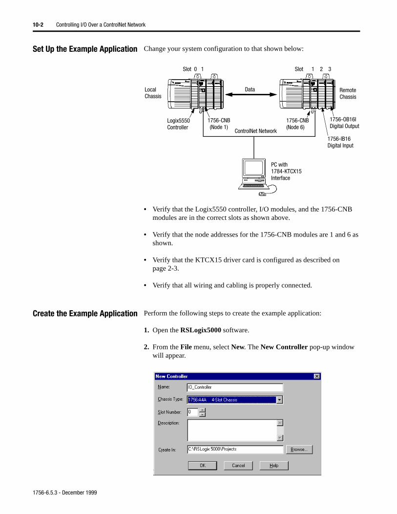
10-2 Controlling I/O Over a ControlNet Network
Set Up the Example Application Change your system configuration to that shown below:
• Verify that the Logix5550 controller, I/O modules, and the 1756-CNB modules are in the correct slots as shown above.
• Verify that the node addresses for the 1756-CNB modules are 1 and 6 as shown.
• Verify that the KTCX15 driver card is configured as described on page 2-3.
• Verify that all wiring and cabling is properly connected.
Create the Example Application Perform the following steps to create the example application:
1. Open the RSLogix5000 software.
2. From the File menu, select New. The New Controller pop-up window will appear.
ControlNet Network
Logix5550 1756-CNB(Node 1)
1756-CNB(Node 6)
LocalChassis
RemoteChassis
PC with1784-KTCX15Interface
Data
Slot 0 1 Slot 1 2 3
1756-IB16Digital Input
1756-OB16IDigital OutputController
1756-6.5.3 - December 1999
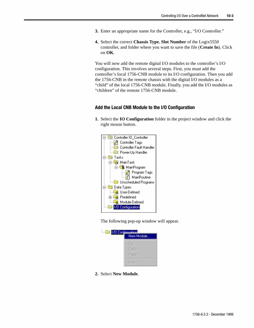
Controlling I/O Over a ControlNet Network 10-3
dd
as
3. Enter an appropriate name for the Controller, e.g., “I/O Controller.”
4. Select the correct Chassis Type, Slot Number of the Logix5550 controller, and folder where you want to save the file (Create In). Click on OK.
You will now add the remote digital I/O modules to the controller’s I/O configuration. This involves several steps. First, you must add the controller’s local 1756-CNB module to its I/O configuration. Then you athe 1756-CNB in the remote chassis with the digital I/O modules as a “child” of the local 1756-CNB module. Finally, you add the I/O modules “children” of the remote 1756-CNB module.
Add the Local CNB Module to the I/O Configuration
1. Select the IO Configuration folder in the project window and click the right mouse button.
The following pop-up window will appear.
2. Select New Module.
1756-6.5.3 - December 1999
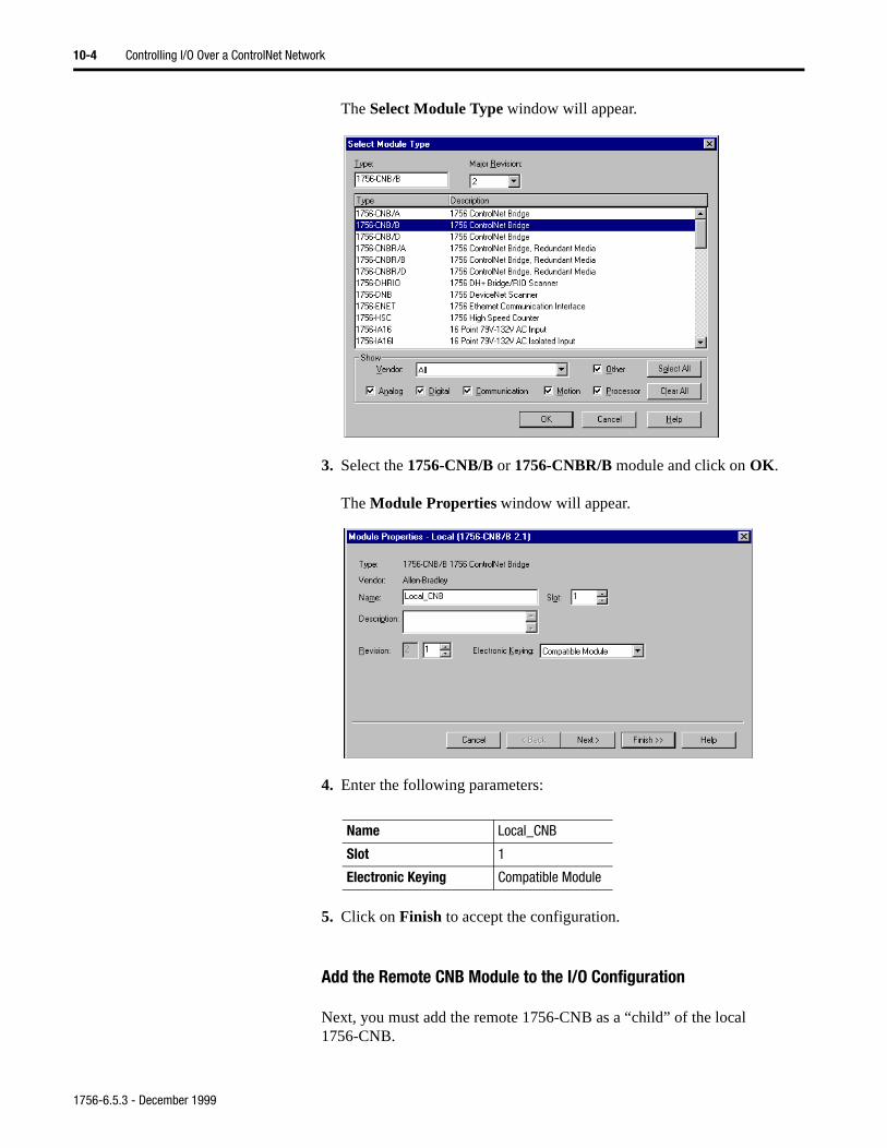
10-4 Controlling I/O Over a ControlNet Network
The Select Module Type window will appear.
3. Select the 1756-CNB/B or 1756-CNBR/B module and click on OK.
The Module Properties window will appear.
4. Enter the following parameters:
5. Click on Finish to accept the configuration.
Add the Remote CNB Module to the I/O Configuration
Next, you must add the remote 1756-CNB as a “child” of the local 1756-CNB.
Name Local_CNB
Slot 1
Electronic Keying Compatible Module
1756-6.5.3 - December 1999
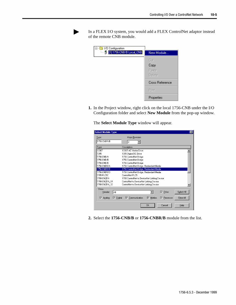
Controlling I/O Over a ControlNet Network 10-5
1. In the Project window, right click on the local 1756-CNB under the I/O Configuration folder and select New Module from the pop-up window.
The Select Module Type window will appear.
2. Select the 1756-CNB/B or 1756-CNBR/B module from the list.
In a FLEX I/O system, you would add a FLEX ControlNet adaptor instead of the remote CNB module.
1756-6.5.3 - December 1999
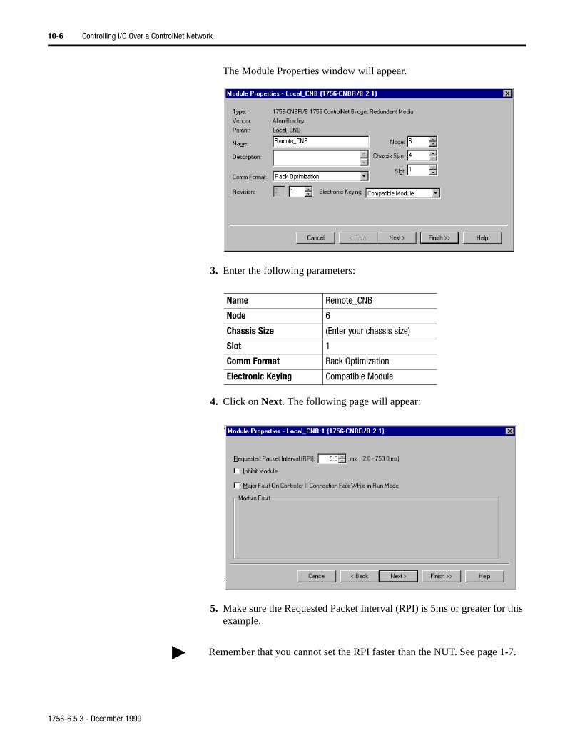
10-6 Controlling I/O Over a ControlNet Network
The Module Properties window will appear.
3. Enter the following parameters:
4. Click on Next. The following page will appear:
5. Make sure the Requested Packet Interval (RPI) is 5ms or greater for this example.
Name Remote_CNB
Node 6
Chassis Size (Enter your chassis size)
Slot 1
Comm Format Rack Optimization
Electronic Keying Compatible Module
Remember that you cannot set the RPI faster than the NUT. See page 1-7.
1756-6.5.3 - December 1999
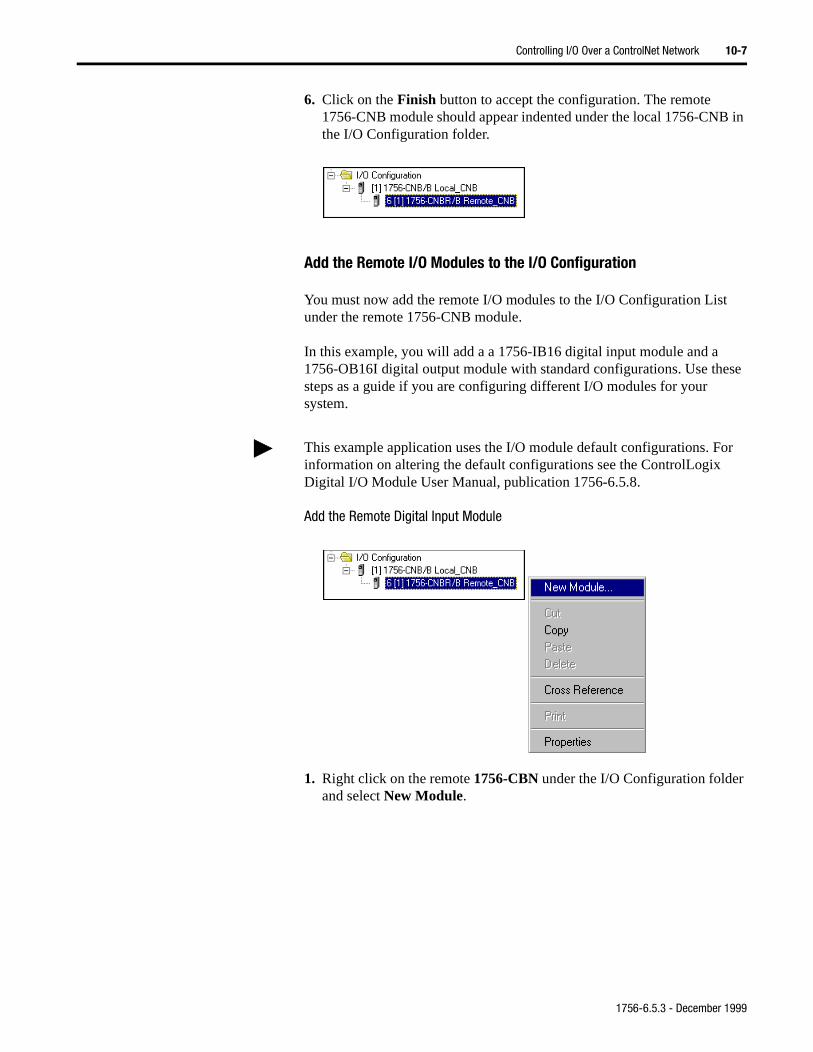
Controlling I/O Over a ControlNet Network 10-7
6. Click on the Finish button to accept the configuration. The remote 1756-CNB module should appear indented under the local 1756-CNB in the I/O Configuration folder.
Add the Remote I/O Modules to the I/O Configuration
You must now add the remote I/O modules to the I/O Configuration List under the remote 1756-CNB module.
In this example, you will add a a 1756-IB16 digital input module and a 1756-OB16I digital output module with standard configurations. Use these steps as a guide if you are configuring different I/O modules for your system.
Add the Remote Digital Input Module
1. Right click on the remote 1756-CBN under the I/O Configuration folder and select New Module.
This example application uses the I/O module default configurations. For information on altering the default configurations see the ControlLogix Digital I/O Module User Manual, publication 1756-6.5.8.
1756-6.5.3 - December 1999
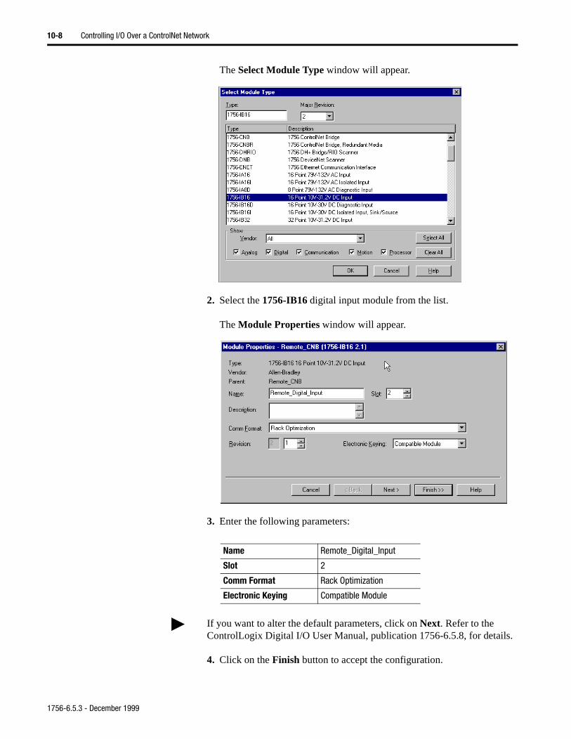
10-8 Controlling I/O Over a ControlNet Network
The Select Module Type window will appear.
2. Select the 1756-IB16 digital input module from the list.
The Module Properties window will appear.
3. Enter the following parameters:
4. Click on the Finish button to accept the configuration.
Name Remote_Digital_Input
Slot 2
Comm Format Rack Optimization
Electronic Keying Compatible Module
If you want to alter the default parameters, click on Next. Refer to the ControlLogix Digital I/O User Manual, publication 1756-6.5.8, for details.
1756-6.5.3 - December 1999
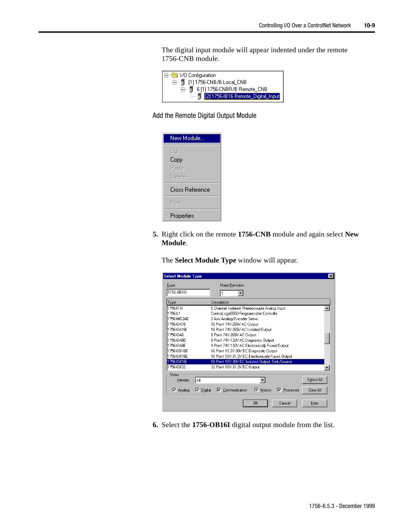
Controlling I/O Over a ControlNet Network 10-9
The digital input module will appear indented under the remote 1756-CNB module.
Add the Remote Digital Output Module
5. Right click on the remote 1756-CNB module and again select New Module.
The Select Module Type window will appear.
6. Select the 1756-OB16I digital output module from the list.
1756-6.5.3 - December 1999
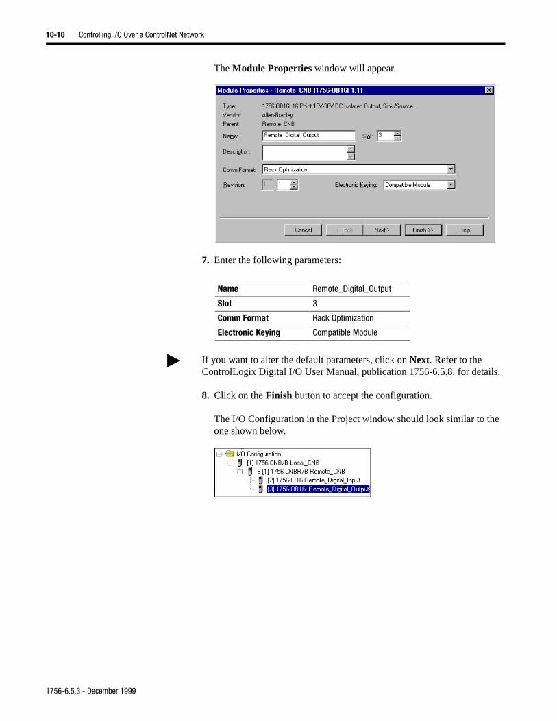
10-10 Controlling I/O Over a ControlNet Network
The Module Properties window will appear.
7. Enter the following parameters:
8. Click on the Finish button to accept the configuration.
The I/O Configuration in the Project window should look similar to the one shown below.
Name Remote_Digital_Output
Slot 3
Comm Format Rack Optimization
Electronic Keying Compatible Module
If you want to alter the default parameters, click on Next. Refer to the ControlLogix Digital I/O User Manual, publication 1756-6.5.8, for details.
1756-6.5.3 - December 1999
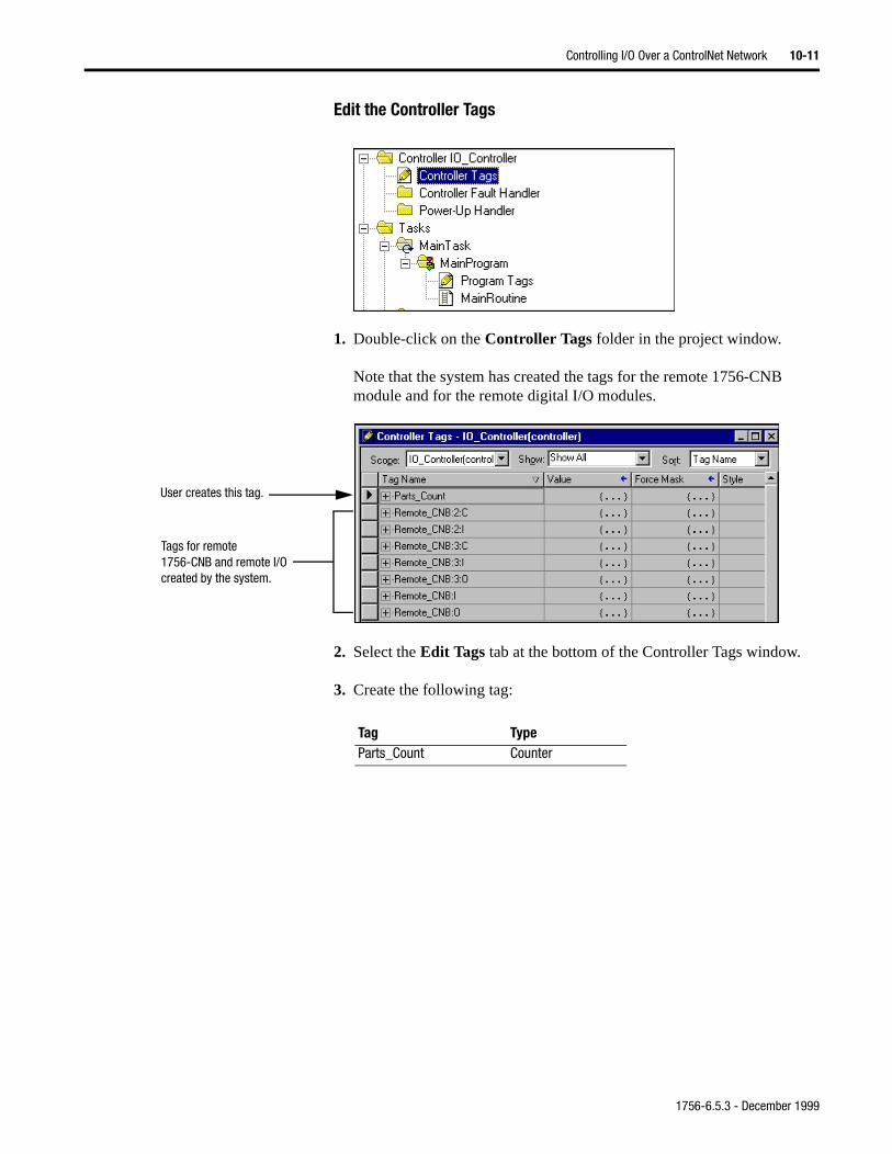
Controlling I/O Over a ControlNet Network 10-11
Edit the Controller Tags
1. Double-click on the Controller Tags folder in the project window.
Note that the system has created the tags for the remote 1756-CNB module and for the remote digital I/O modules.
2. Select the Edit Tags tab at the bottom of the Controller Tags window.
3. Create the following tag:
Tags for remote 1756-CNB and remote I/O created by the system.
User creates this tag.
Tag TypeParts_Count Counter
1756-6.5.3 - December 1999
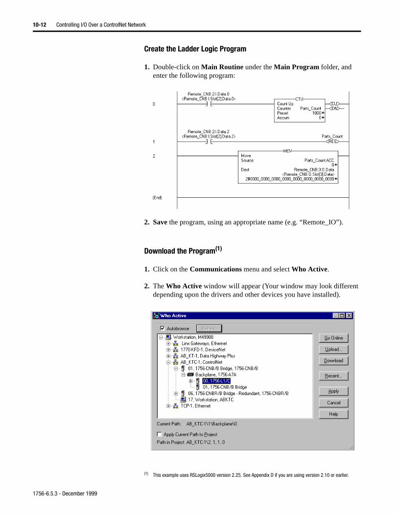
10-12 Controlling I/O Over a ControlNet Network
Create the Ladder Logic Program
1. Double-click on Main Routine under the Main Program folder, and enter the following program:
2. Save the program, using an appropriate name (e.g. “Remote_IO”).
Download the Program(1)
1. Click on the Communications menu and select Who Active.
2. The Who Active window will appear (Your window may look differentdepending upon the drivers and other devices you have installed).
(1) This example uses RSLogix5000 version 2.25. See Appendix D if you are using version 2.10 or earlier.
1756-6.5.3 - December 1999
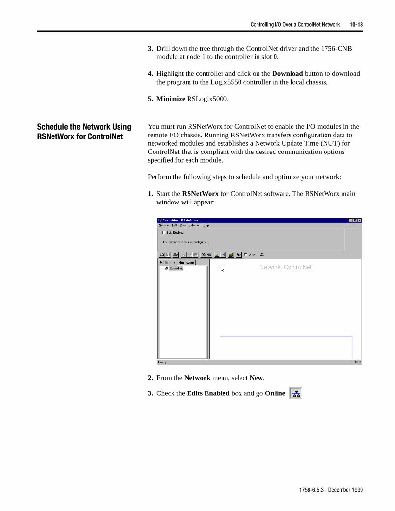
Controlling I/O Over a ControlNet Network 10-13
3. Drill down the tree through the ControlNet driver and the 1756-CNB module at node 1 to the controller in slot 0.
4. Highlight the controller and click on the Download button to download the program to the Logix5550 controller in the local chassis.
5. Minimize RSLogix5000.
Schedule the Network Using RSNetWorx for ControlNet
You must run RSNetWorx for ControlNet to enable the I/O modules in the remote I/O chassis. Running RSNetWorx transfers configuration data to networked modules and establishes a Network Update Time (NUT) for ControlNet that is compliant with the desired communication options specified for each module.
Perform the following steps to schedule and optimize your network:
1. Start the RSNetWorx for ControlNet software. The RSNetWorx main window will appear:
2. From the Network menu, select New.
3. Check the Edits Enabled box and go Online
1756-6.5.3 - December 1999
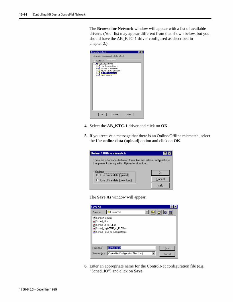
10-14 Controlling I/O Over a ControlNet Network
The Browse for Network window will appear with a list of available drivers. (Your list may appear different from that shown below, but you should have the AB_KTC-1 driver configured as described in chapter 2.).
4. Select the AB_KTC-1 driver and click on OK.
5. If you receive a message that there is an Online/Offline mismatch, select the Use online data (upload) option and click on OK.
The Save As window will appear:
6. Enter an appropriate name for the ControlNet configuration file (e.g., “Sched_IO”) and click on Save.
1756-6.5.3 - December 1999
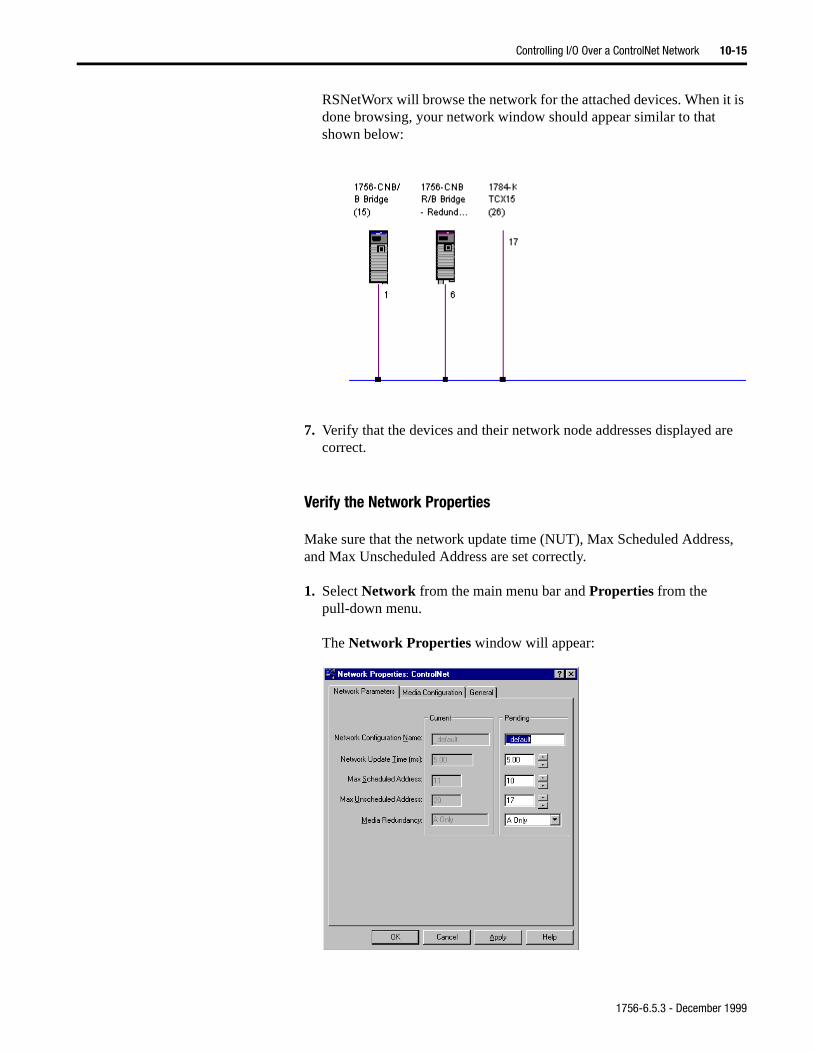
Controlling I/O Over a ControlNet Network 10-15
RSNetWorx will browse the network for the attached devices. When it is done browsing, your network window should appear similar to that shown below:
7. Verify that the devices and their network node addresses displayed are correct.
Verify the Network Properties
Make sure that the network update time (NUT), Max Scheduled Address, and Max Unscheduled Address are set correctly.
1. Select Network from the main menu bar and Properties from the pull-down menu.
The Network Properties window will appear:
1756-6.5.3 - December 1999
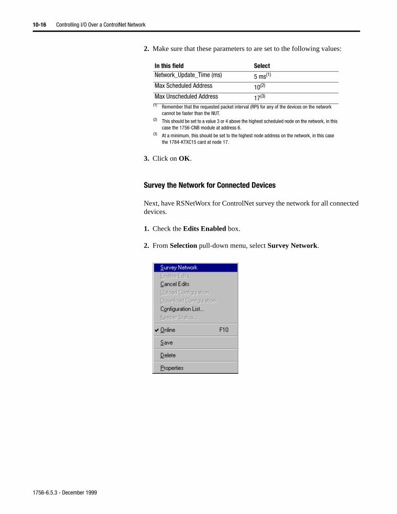
10-16 Controlling I/O Over a ControlNet Network
2. Make sure that these parameters to are set to the following values:
3. Click on OK.
Survey the Network for Connected Devices
Next, have RSNetWorx for ControlNet survey the network for all connected devices.
1. Check the Edits Enabled box.
2. From Selection pull-down menu, select Survey Network.
In this field SelectNetwork_Update_Time (ms) 5 ms(1)
(1) Remember that the requested packet interval (RPI) for any of the devices on the network cannot be faster than the NUT.
Max Scheduled Address 10(2)
(2) This should be set to a value 3 or 4 above the highest scheduled node on the network, in this case the 1756-CNB module at address 6.
Max Unscheduled Address 17(3)
(3) At a minimum, this should be set to the highest node address on the network, in this case the 1784-KTXC15 card at node 17.
1756-6.5.3 - December 1999
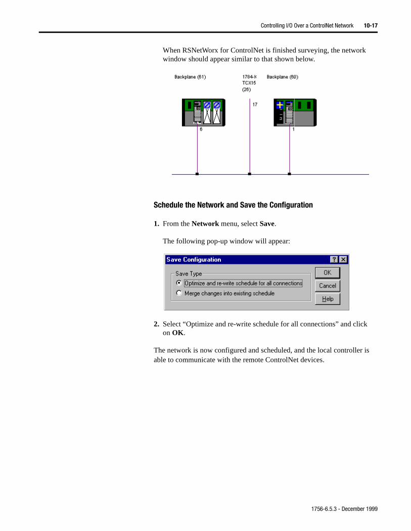
Controlling I/O Over a ControlNet Network 10-17
is
When RSNetWorx for ControlNet is finished surveying, the network window should appear similar to that shown below.
Schedule the Network and Save the Configuration
1. From the Network menu, select Save.
The following pop-up window will appear:
2. Select “Optimize and re-write schedule for all connections” and clickon OK.
The network is now configured and scheduled, and the local controller able to communicate with the remote ControlNet devices.
1756-6.5.3 - December 1999
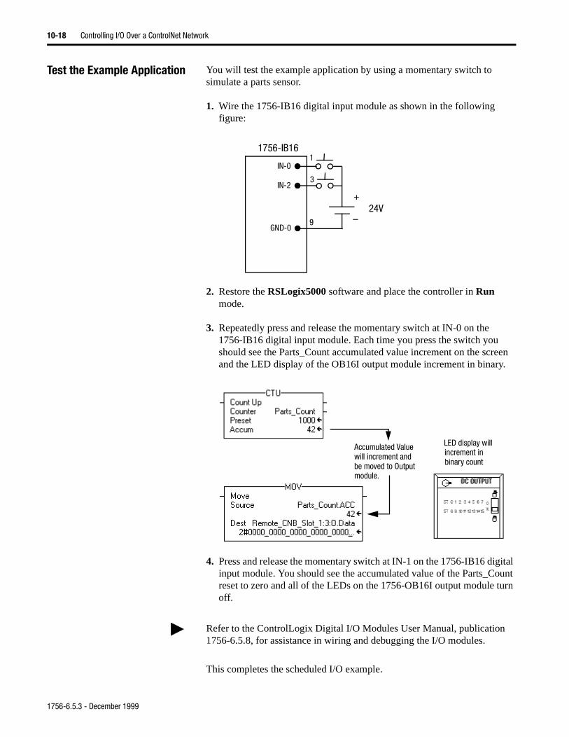
10-18 Controlling I/O Over a ControlNet Network
Test the Example Application You will test the example application by using a momentary switch to simulate a parts sensor.
1. Wire the 1756-IB16 digital input module as shown in the following figure:
2. Restore the RSLogix5000 software and place the controller in Run mode.
3. Repeatedly press and release the momentary switch at IN-0 on the 1756-IB16 digital input module. Each time you press the switch you should see the Parts_Count accumulated value increment on the screen and the LED display of the OB16I output module increment in binary.
4. Press and release the momentary switch at IN-1 on the 1756-IB16 digital input module. You should see the accumulated value of the Parts_Count reset to zero and all of the LEDs on the 1756-OB16I output module turn off.
This completes the scheduled I/O example.
IN-0
IN-2
GND-0
1
3
9
+
–
1756-IB16
24V
Accumulated Valuewill increment andbe moved to Outputmodule.
LED display will increment inbinary count
Refer to the ControlLogix Digital I/O Modules User Manual, publication 1756-6.5.8, for assistance in wiring and debugging the I/O modules.
1756-6.5.3 - December 1999
as ram the ation
Chapter 11
Adding an I/O Chassis to an Existing ControlNet Network
About the Example Application Each 1756-CNB interface module can support up to 64 bidirectional connections. This example application expands the ControlNet network from the previous chapter by adding another remote I/O chassis. The new remote chassis contains another “child” 1756-CNB module (configurednode 3) in slot 0 and an analog output module in slot 1. The ladder progof the previous chapter is modified to produce a varying signal at one ofanalog output channels. Note that these changes do not affect the operof the digital I/O modules in the first remote chassis.
What you will do See page
Set Up the Example Application 11-2
Create the Example Application 11-2
Add the Second Remote 1756-CNB Module to the I/O Configuration
11-3
Add the Remote Analog I/O Module to the I/O Configuration
11-5
Edit the Controller Tags 11-9
Modify the Ladder Program 11-10
Download the Program 11-10
Schedule the Network Using RSNetWorx for ControlNet 11-11
Test the Example Application 11-16
1756-6.5.3 - December 1999
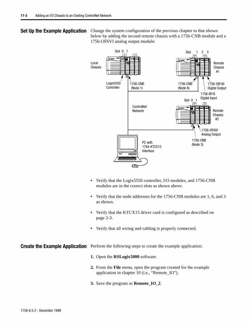
11-2 Adding an I/O Chassis to an Existing ControlNet Network
Set Up the Example Application Change the system configuration of the previous chapter to that shown below by adding the second remote chassis with a 1756-CNB module and a 1756-OF6VI analog output module:
• Verify that the Logix5550 controller, I/O modules, and 1756-CNB modules are in the correct slots as shown above.
• Verify that the node addresses for the 1756-CNB modules are 1, 6, and 3 as shown.
• Verify that the KTCX15 driver card is configured as described on page 2-3.
• Verify that all wiring and cabling is properly connected.
Create the Example Application Perform the following steps to create the example application:
1. Open the RSLogix5000 software.
2. From the File menu, open the program created for the example application in chapter 10 (i.e., “Remote_IO”).
3. Save the program as Remote_IO_2.
ControlNet
Logix5550 1756-CNB(Node 1)
1756-CNB(Node 6)
LocalChassis
RemoteChassis
PC with1784-KTCX15Interface
Slot 0 1 Slot 1 2 3
1756-IB16Digital Input
1756-OB16IDigital OutputController
Network
#1
RemoteChassis
#2
1756-CNB(Node 3)
1756-OF6VIAnalog Output
Slot 0 1
1756-6.5.3 - December 1999
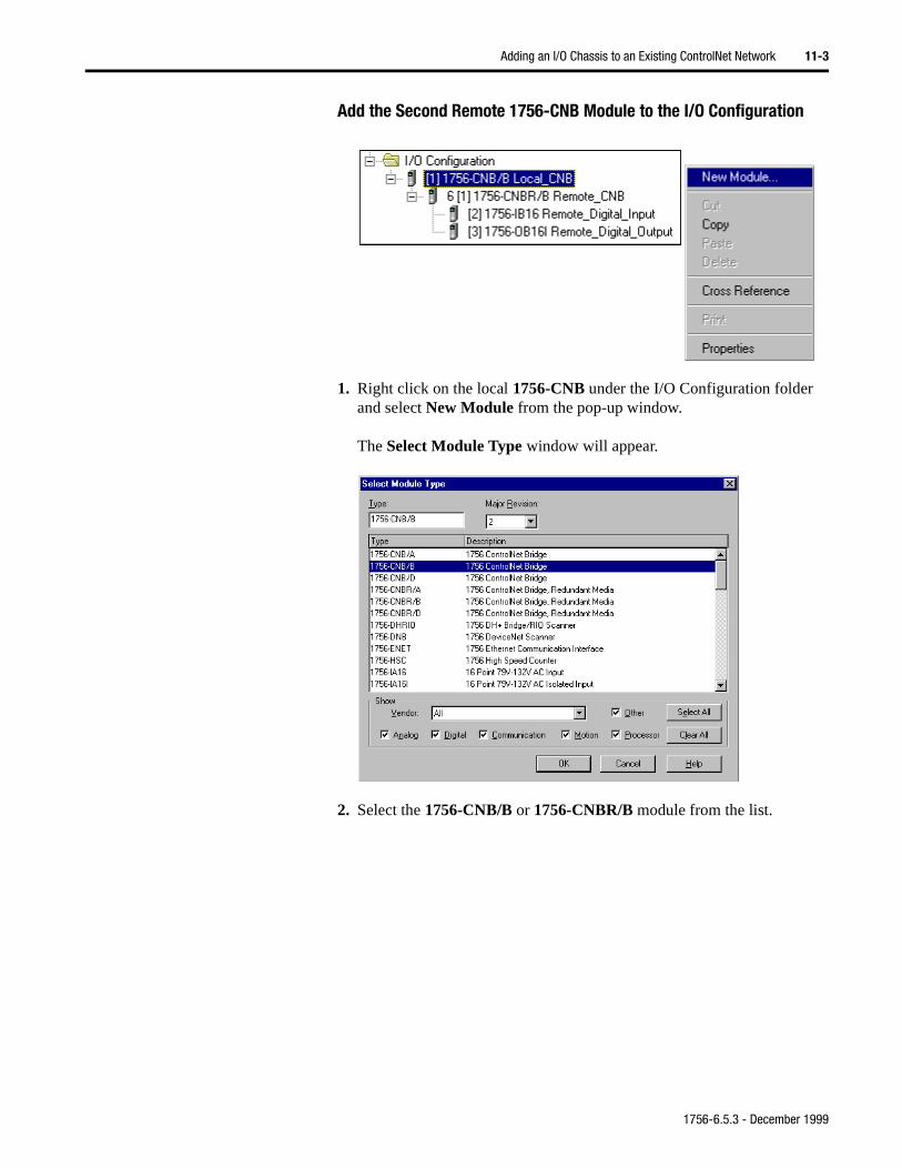
Adding an I/O Chassis to an Existing ControlNet Network 11-3
Add the Second Remote 1756-CNB Module to the I/O Configuration
1. Right click on the local 1756-CNB under the I/O Configuration folder and select New Module from the pop-up window.
The Select Module Type window will appear.
2. Select the 1756-CNB/B or 1756-CNBR/B module from the list.
1756-6.5.3 - December 1999
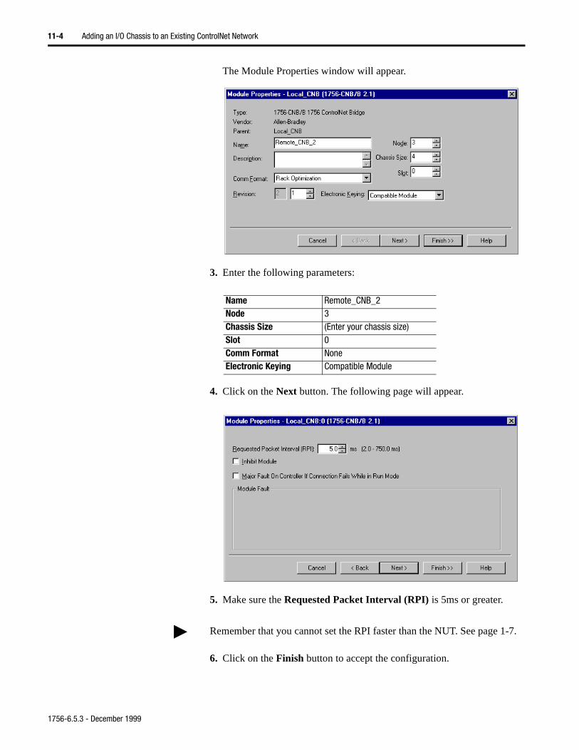
11-4 Adding an I/O Chassis to an Existing ControlNet Network
The Module Properties window will appear.
3. Enter the following parameters:
4. Click on the Next button. The following page will appear.
5. Make sure the Requested Packet Interval (RPI) is 5ms or greater.
6. Click on the Finish button to accept the configuration.
Name Remote_CNB_2Node 3Chassis Size (Enter your chassis size)Slot 0Comm Format NoneElectronic Keying Compatible Module
Remember that you cannot set the RPI faster than the NUT. See page 1-7.
1756-6.5.3 - December 1999
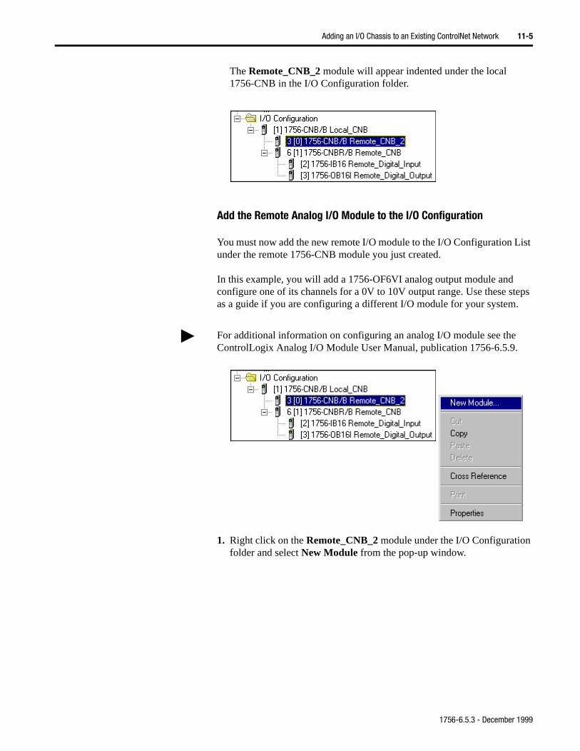
Adding an I/O Chassis to an Existing ControlNet Network 11-5
The Remote_CNB_2 module will appear indented under the local 1756-CNB in the I/O Configuration folder.
Add the Remote Analog I/O Module to the I/O Configuration
You must now add the new remote I/O module to the I/O Configuration List under the remote 1756-CNB module you just created.
In this example, you will add a 1756-OF6VI analog output module and configure one of its channels for a 0V to 10V output range. Use these steps as a guide if you are configuring a different I/O module for your system.
1. Right click on the Remote_CNB_2 module under the I/O Configuration folder and select New Module from the pop-up window.
For additional information on configuring an analog I/O module see the ControlLogix Analog I/O Module User Manual, publication 1756-6.5.9.
1756-6.5.3 - December 1999

11-6 Adding an I/O Chassis to an Existing ControlNet Network
The Select Module Type window will appear.
2. Select the 1756-OF6VI analog output module from the list.
The Module Properties window will appear.
3. Enter the following parameters:
You will now configure the channel settings of the I/O module. When you do this a series of pages will appear in the Module Properties window.
Name Remote_Analog_OutputSlot 1Comm Format Float Data (default)Electronic Keying Compatible Module
For a detailed explanation of the following pages, see the ControlLogix Analog I/O User Manual, publication 1756-6.5.9.
1756-6.5.3 - December 1999
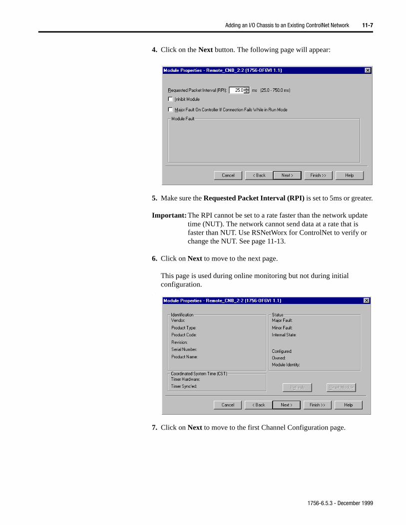
Adding an I/O Chassis to an Existing ControlNet Network 11-7
4. Click on the Next button. The following page will appear:
5. Make sure the Requested Packet Interval (RPI) is set to 5ms or greater.
Important: The RPI cannot be set to a rate faster than the network update time (NUT). The network cannot send data at a rate that is faster than NUT. Use RSNetWorx for ControlNet to verify or change the NUT. See page 11-13.
6. Click on Next to move to the next page.
This page is used during online monitoring but not during initial configuration.
.
7. Click on Next to move to the first Channel Configuration page.
1756-6.5.3 - December 1999
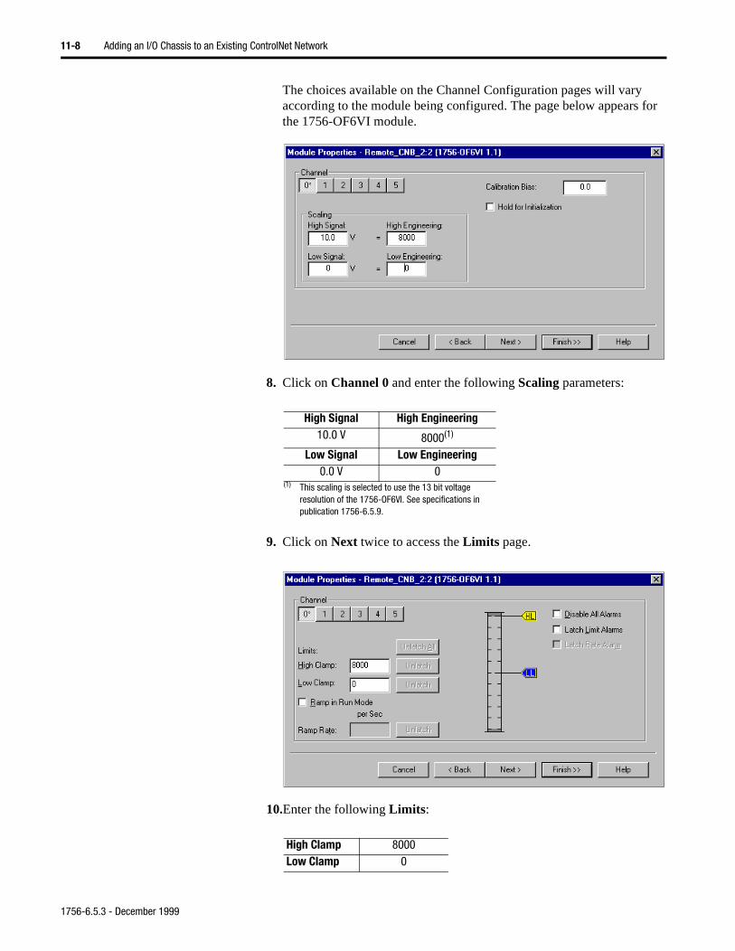
11-8 Adding an I/O Chassis to an Existing ControlNet Network
The choices available on the Channel Configuration pages will vary according to the module being configured. The page below appears for the 1756-OF6VI module.
8. Click on Channel 0 and enter the following Scaling parameters:
9. Click on Next twice to access the Limits page.
10.Enter the following Limits:
High Signal High Engineering10.0 V 8000(1)
(1) This scaling is selected to use the 13 bit voltage resolution of the 1756-OF6VI. See specifications in publication 1756-6.5.9.
Low Signal Low Engineering0.0 V 0
High Clamp 8000Low Clamp 0
1756-6.5.3 - December 1999
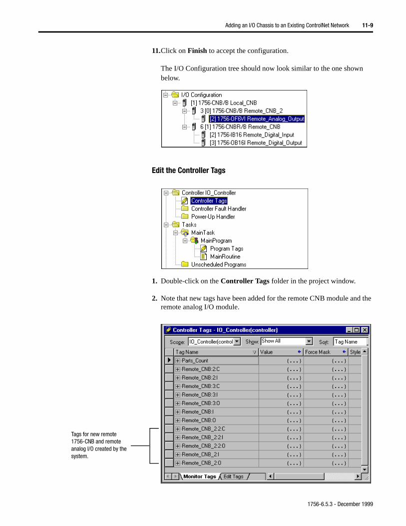
Adding an I/O Chassis to an Existing ControlNet Network 11-9
11.Click on Finish to accept the configuration.
The I/O Configuration tree should now look similar to the one shown below.
Edit the Controller Tags
1. Double-click on the Controller Tags folder in the project window.
2. Note that new tags have been added for the remote CNB module and the remote analog I/O module.
Tags for new remote 1756-CNB and remote analog I/O created by the system.
1756-6.5.3 - December 1999
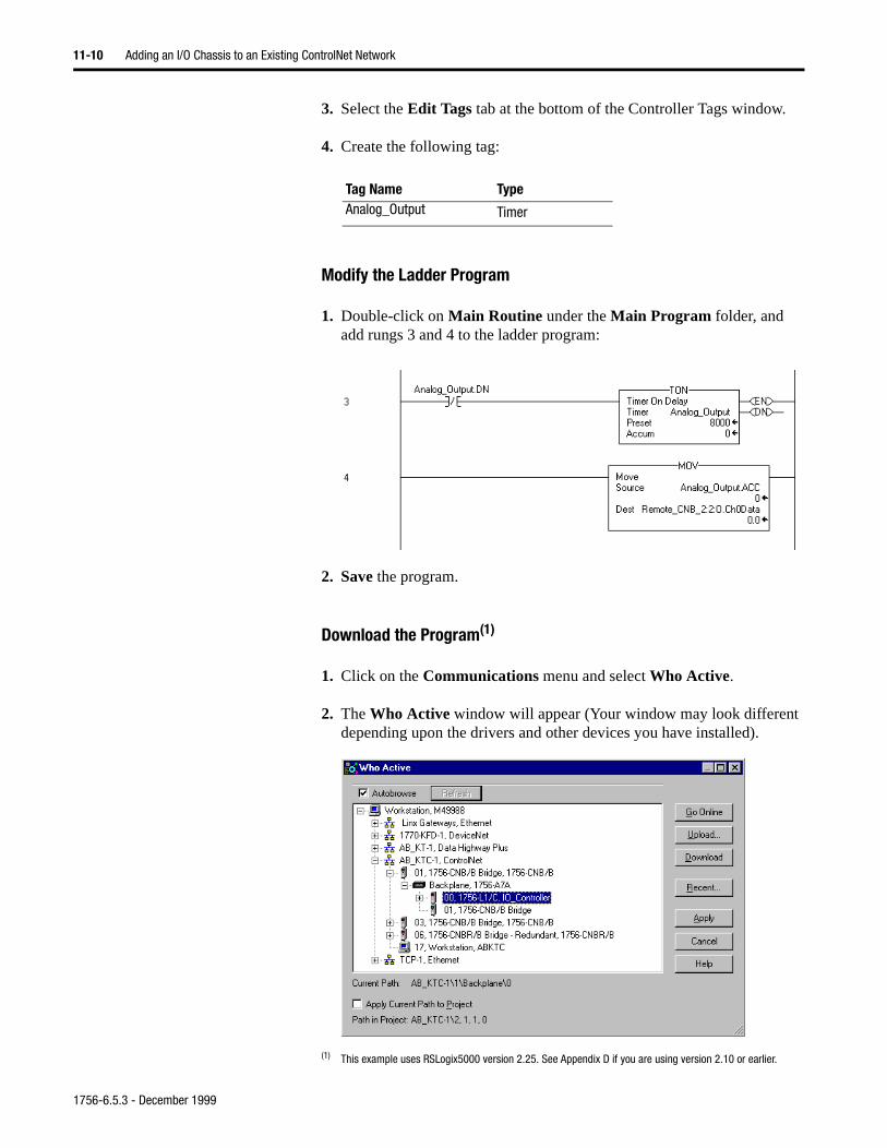
11-10 Adding an I/O Chassis to an Existing ControlNet Network
3. Select the Edit Tags tab at the bottom of the Controller Tags window.
4. Create the following tag:
Modify the Ladder Program
1. Double-click on Main Routine under the Main Program folder, and add rungs 3 and 4 to the ladder program:
2. Save the program.
Download the Program(1)
1. Click on the Communications menu and select Who Active.
2. The Who Active window will appear (Your window may look different depending upon the drivers and other devices you have installed).
Tag Name TypeAnalog_Output Timer
(1) This example uses RSLogix5000 version 2.25. See Appendix D if you are using version 2.10 or earlier.
1756-6.5.3 - December 1999
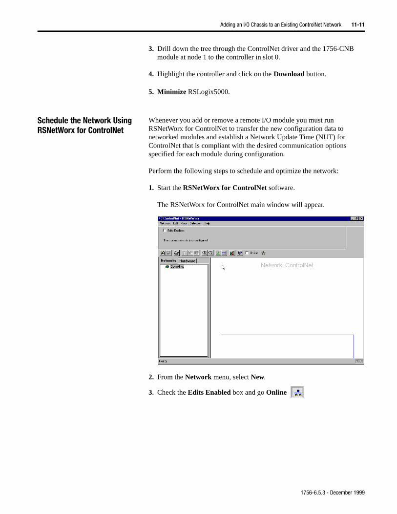
Adding an I/O Chassis to an Existing ControlNet Network 11-11
3. Drill down the tree through the ControlNet driver and the 1756-CNB module at node 1 to the controller in slot 0.
4. Highlight the controller and click on the Download button.
5. Minimize RSLogix5000.
Schedule the Network Using RSNetWorx for ControlNet
Whenever you add or remove a remote I/O module you must run RSNetWorx for ControlNet to transfer the new configuration data to networked modules and establish a Network Update Time (NUT) for ControlNet that is compliant with the desired communication options specified for each module during configuration.
Perform the following steps to schedule and optimize the network:
1. Start the RSNetWorx for ControlNet software.
The RSNetWorx for ControlNet main window will appear.
2. From the Network menu, select New.
3. Check the Edits Enabled box and go Online
1756-6.5.3 - December 1999
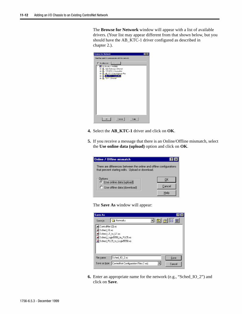
11-12 Adding an I/O Chassis to an Existing ControlNet Network
The Browse for Network window will appear with a list of available drivers. (Your list may appear different from that shown below, but you should have the AB_KTC-1 driver configured as described in chapter 2.).
4. Select the AB_KTC-1 driver and click on OK.
5. If you receive a message that there is an Online/Offline mismatch, select the Use online data (upload) option and click on OK.
The Save As window will appear:
6. Enter an appropriate name for the network (e.g., “Sched_IO_2”) andclick on Save.
1756-6.5.3 - December 1999
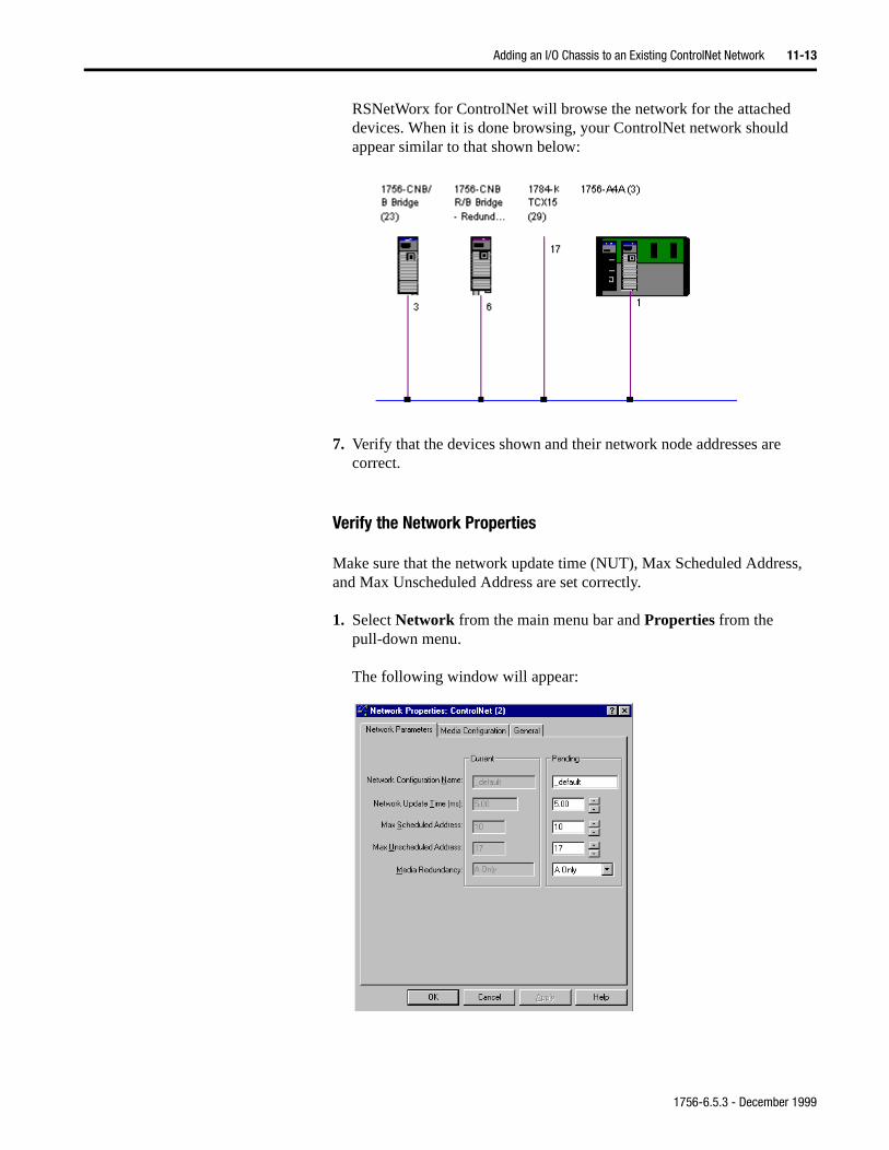
Adding an I/O Chassis to an Existing ControlNet Network 11-13
RSNetWorx for ControlNet will browse the network for the attached devices. When it is done browsing, your ControlNet network should appear similar to that shown below:
7. Verify that the devices shown and their network node addresses are correct.
Verify the Network Properties
Make sure that the network update time (NUT), Max Scheduled Address, and Max Unscheduled Address are set correctly.
1. Select Network from the main menu bar and Properties from the pull-down menu.
The following window will appear:
1756-6.5.3 - December 1999
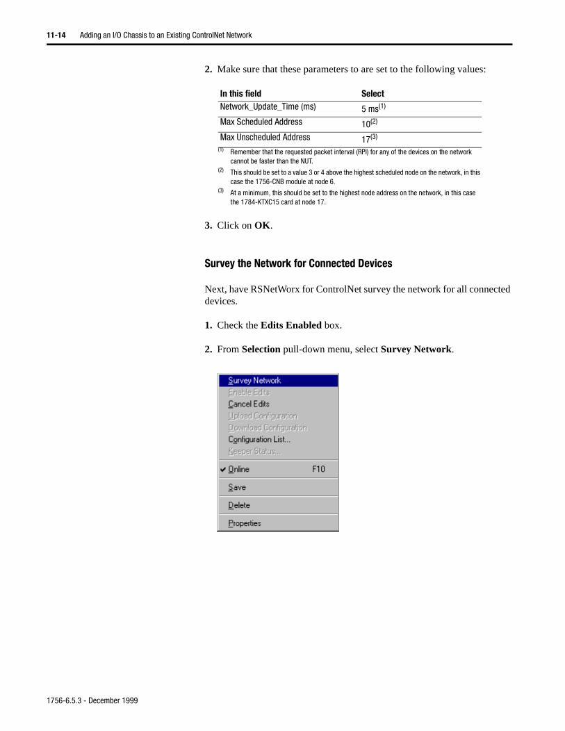
11-14 Adding an I/O Chassis to an Existing ControlNet Network
2. Make sure that these parameters to are set to the following values:
3. Click on OK.
Survey the Network for Connected Devices
Next, have RSNetWorx for ControlNet survey the network for all connected devices.
1. Check the Edits Enabled box.
2. From Selection pull-down menu, select Survey Network.
In this field SelectNetwork_Update_Time (ms) 5 ms(1)
(1) Remember that the requested packet interval (RPI) for any of the devices on the network cannot be faster than the NUT.
Max Scheduled Address 10(2)
(2) This should be set to a value 3 or 4 above the highest scheduled node on the network, in this case the 1756-CNB module at node 6.
Max Unscheduled Address 17(3)
(3) At a minimum, this should be set to the highest node address on the network, in this case the 1784-KTXC15 card at node 17.
1756-6.5.3 - December 1999
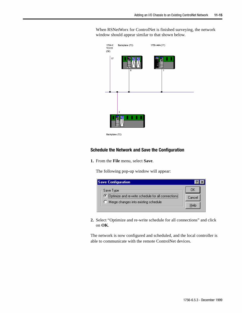
Adding an I/O Chassis to an Existing ControlNet Network 11-15
is
When RSNetWorx for ControlNet is finished surveying, the network window should appear similar to that shown below.
Schedule the Network and Save the Configuration
1. From the File menu, select Save.
The following pop-up window will appear:
2. Select “Optimize and re-write schedule for all connections” and clickon OK.
The network is now configured and scheduled, and the local controller able to communicate with the remote ControlNet devices.
1756-6.5.3 - December 1999
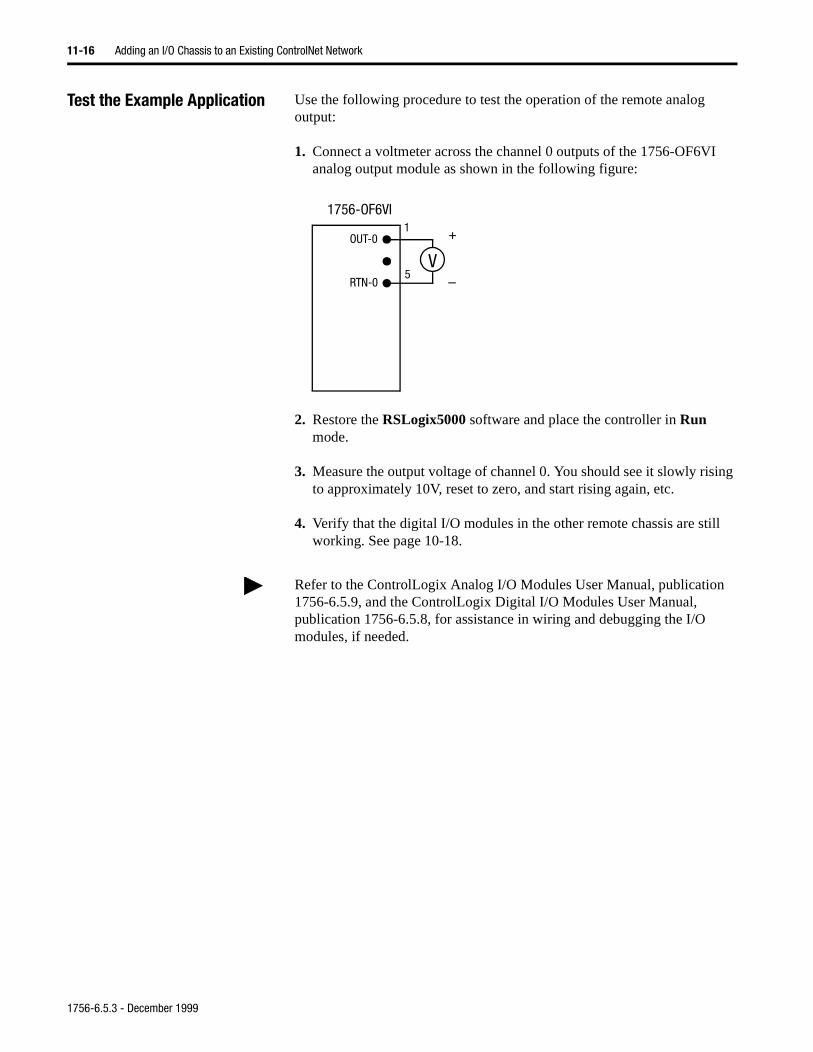
11-16 Adding an I/O Chassis to an Existing ControlNet Network
Test the Example Application Use the following procedure to test the operation of the remote analog output:
1. Connect a voltmeter across the channel 0 outputs of the 1756-OF6VI analog output module as shown in the following figure:
2. Restore the RSLogix5000 software and place the controller in Run mode.
3. Measure the output voltage of channel 0. You should see it slowly rising to approximately 10V, reset to zero, and start rising again, etc.
4. Verify that the digital I/O modules in the other remote chassis are still working. See page 10-18.
OUT-0
RTN-0
1
5
1756-OF6VI
V
+
–
Refer to the ControlLogix Analog I/O Modules User Manual, publication 1756-6.5.9, and the ControlLogix Digital I/O Modules User Manual, publication 1756-6.5.8, for assistance in wiring and debugging the I/O modules, if needed.
1756-6.5.3 - December 1999
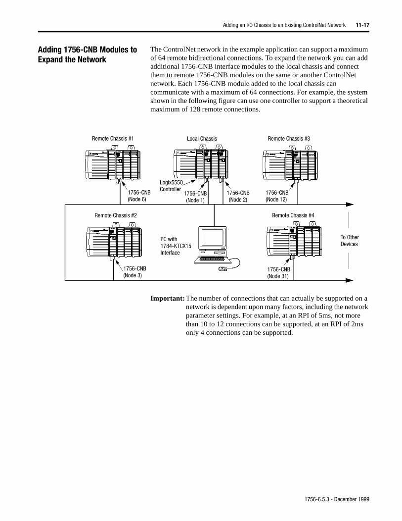
Adding an I/O Chassis to an Existing ControlNet Network 11-17
Adding 1756-CNB Modules to Expand the Network
The ControlNet network in the example application can support a maximum of 64 remote bidirectional connections. To expand the network you can add additional 1756-CNB interface modules to the local chassis and connect them to remote 1756-CNB modules on the same or another ControlNet network. Each 1756-CNB module added to the local chassis can communicate with a maximum of 64 connections. For example, the system shown in the following figure can use one controller to support a theoretical maximum of 128 remote connections.
Important: The number of connections that can actually be supported on a network is dependent upon many factors, including the network parameter settings. For example, at an RPI of 5ms, not more than 10 to 12 connections can be supported, at an RPI of 2ms only 4 connections can be supported.
Logix5550
1756-CNB(Node 1)
1756-CNB(Node 12)
Local Chassis Remote Chassis #3
PC with1784-KTCX15Interface
Controller
Remote Chassis #4
1756-CNB(Node 31)
1756-CNB(Node 6)
Remote Chassis #1
1756-CNB(Node 3)
1756-CNB(Node 2)
To OtherDevices
Remote Chassis #2
1756-6.5.3 - December 1999
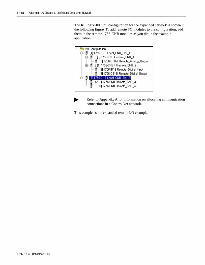
11-18 Adding an I/O Chassis to an Existing ControlNet Network
The RSLogix5000 I/O configuration for the expanded network is shown in the following figure. To add remote I/O modules to the configuration, add them to the remote 1756-CNB modules as you did in the example application.
This completes the expanded remote I/O example.
Refer to Appendix A for information on allocating communication connections in a ControlNet network.
1756-6.5.3 - December 1999
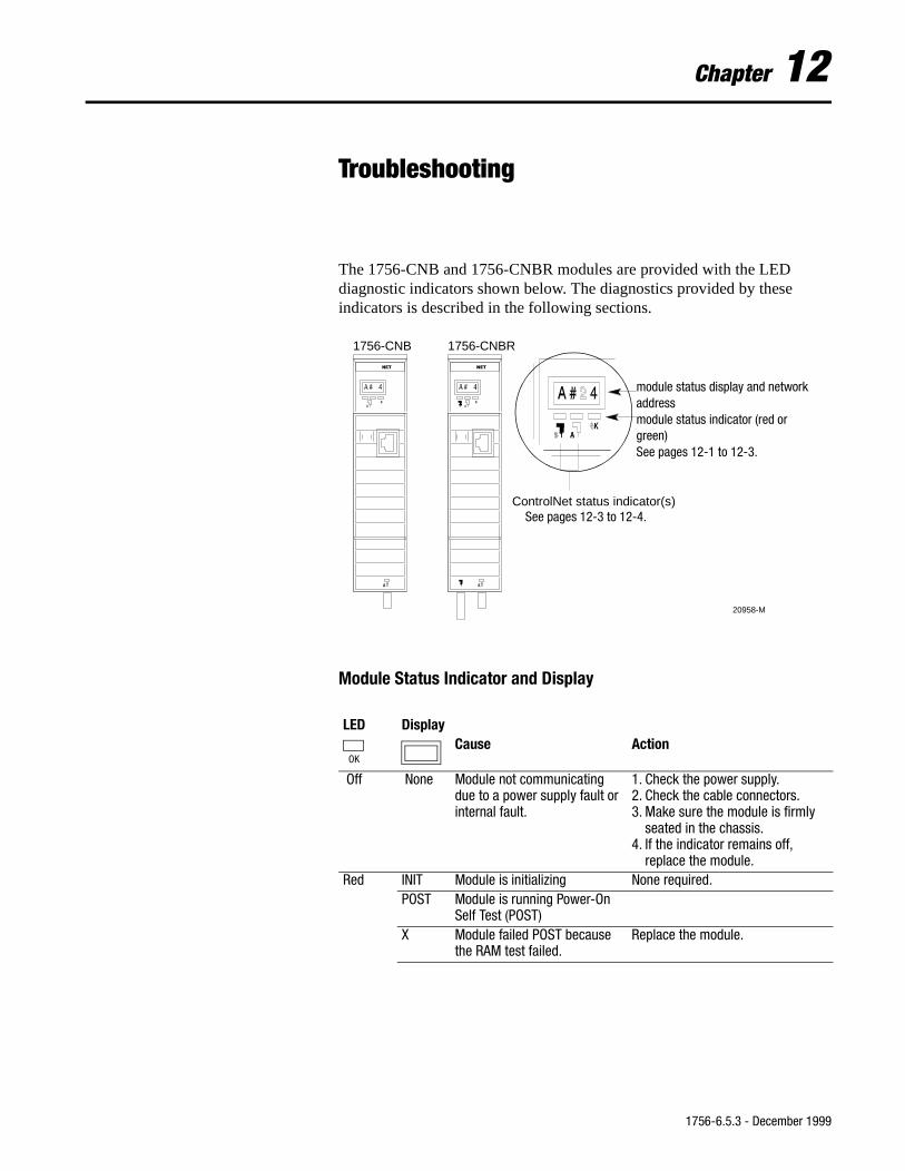
Chapter 12
Troubleshooting
The 1756-CNB and 1756-CNBR modules are provided with the LED diagnostic indicators shown below. The diagnostics provided by these indicators is described in the following sections.
Module Status Indicator and Display
LED DisplayCause Action
Off None Module not communicating due to a power supply fault or internal fault.
1. Check the power supply.2. Check the cable connectors.3. Make sure the module is firmly
seated in the chassis.4. If the indicator remains off,
replace the module.Red INIT Module is initializing None required.
POST Module is running Power-On Self Test (POST)
X Module failed POST because the RAM test failed.
Replace the module.
1756-CNB 1756-CNBR
20958-M
ControlNet status indicator(s)
module status display and network addressdescribed on page 14 module status indicator(red or green)described on page 11
module status display and network address module status indicator (red or green)See pages 12-1 to 12-3.
See pages 12-3 to 12-4.
OK
1756-6.5.3 - December 1999
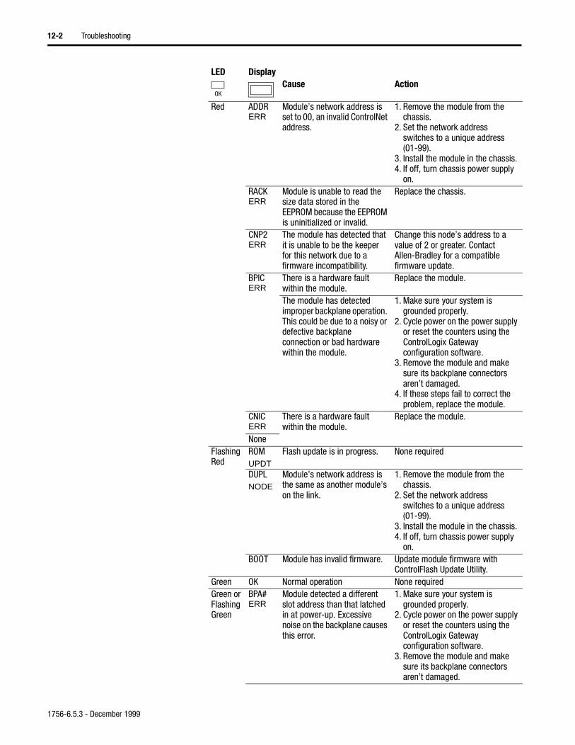
12-2 Troubleshooting
Red ADDR ERR
Module’s network address is set to 00, an invalid ControlNet address.
1. Remove the module from the chassis.
2. Set the network address switches to a unique address (01-99).
3. Install the module in the chassis.4. If off, turn chassis power supply
on.RACK ERR
Module is unable to read the size data stored in the EEPROM because the EEPROM is uninitialized or invalid.
Replace the chassis.
CNP2 ERR
The module has detected that it is unable to be the keeper for this network due to a firmware incompatibility.
Change this node’s address to a value of 2 or greater. Contact Allen-Bradley for a compatible firmware update.
BPICERR
There is a hardware fault within the module.
Replace the module.
The module has detected improper backplane operation. This could be due to a noisy or defective backplane connection or bad hardware within the module.
1. Make sure your system is grounded properly.
2. Cycle power on the power supply or reset the counters using the ControlLogix Gateway configuration software.
3. Remove the module and make sure its backplane connectors aren’t damaged.
4. If these steps fail to correct the problem, replace the module.
CNICERR
There is a hardware fault within the module.
Replace the module.
NoneFlashing Red
ROMUPDT
Flash update is in progress. None required
DUPLNODE
Module’s network address is the same as another module’s on the link.
1. Remove the module from the chassis.
2. Set the network address switches to a unique address (01-99).
3. Install the module in the chassis.4. If off, turn chassis power supply
on.BOOT Module has invalid firmware. Update module firmware with
ControlFlash Update Utility.Green OK Normal operation None requiredGreen or Flashing Green
BPA#ERR
Module detected a different slot address than that latched in at power-up. Excessive noise on the backplane causes this error.
1. Make sure your system is grounded properly.
2. Cycle power on the power supply or reset the counters using the ControlLogix Gateway configuration software.
3. Remove the module and make sure its backplane connectors aren’t damaged.
LED DisplayCause Action
OK
1756-6.5.3 - December 1999
Troubleshooting 12-3
ControlNet Network Status Indicators
• steady - indicator is on continuously in the defined state.
• alternating - the two indicators alternate between the two defined states at the same time (applies to both indicators viewed together). The two indicators are always in opposite states, out of phase.
• flashing - the indicator alternates between the two defined states (applies to each indicator viewed independent of the other). If both indicators are flashing, they must flash together, in phase.
Green or Flashing Green
BPRXERR
Too many CRC errors being generated by the multicast backplane receiver, so the backplane multicast receivers have been shut off.
Cycle power on the module or send a reset to the module. If condition persists, replace the module. (This error is caused by a module hardware fault or noisy backplane.)
KPRERR
The configured keeper object within the module is unable to operate on the attached network.
1. Verify that this module is attached to the correct network.
2. Rerun RSNetworx on this network to update the module’s keeper object.
BWXCED
Module is receiving too much network traffic and connections are timing out. The network bandwidth has been exceeded.
None required (temporary condition).If this happens frequently, add another 1756-CNB or -CNBR and split the traffic between them.
SWERR
Module’s network address has been changed since module power-up.
1. Optional, see page.)Turn chassis power supply off.
2. Remove the module from the chassis.
3. Set the network address switches to a unique address (01-99).
4. Install the module in the chassis.5. If off, turn chassis power supply
on.Flashing Green
NETERR
Network cabling error or no other nodes on network.
Re-check your network cabling and make sure another node on the network is active (online).
Cause Action
Off No power None or power up.Steady red Faulted unit Cycle power or reset unit
If fault persists, contact A-B representative or distributor.
Alternating red/green
Self-test None
LED DisplayCause Action
OK
andA B
1756-6.5.3 - December 1999
12-4 Troubleshooting
Alternating red/off Incorrect node configuration Check network address and other ControlNet configuration parameters.
Off Channel disabled Program network for redundant media, if required.
Steady green Normal operation None.Flashing green/off Temporary errors None; unit will self-correct.
Node is not configured to go on line
Make sure the Keeper node is present and working.(1)
Flashing red/off Media fault Check media for broken cables, loose connectors, missing terminators, etc.
No other nodes present on network
Add other nodes to the network.
Flashing red/green Incorrect network configuration
Cycle power or reset unit.If fault persists, contact A-B representative or distributor.
(1) The Keeper node is the node responsible for distributing ControlNet configuration data to all nodes on the network.
Cause Actionand
A B
1756-6.5.3 - December 1999
Appendix A
Allocating Communication Connections
What This Appendix Contains This appendix describes how to determine the connection requirements for a ControlLogix system.
How the ControlLogix System Uses Connections
The ControlLogix system uses a connection to establish a communication link between two devices. This includes Logix5550 controllers, communication modules, input/output modules, produced/consumed tags, and messages. Connections take many forms:
• Logix5550 controller direct to local I/O or local communication module• Logix5550 controller direct to remote I/O or remote communication
module• Logix5550 controller to remote chassis (rack optimized)• produced and consumed tags• messaging, including block-transfers
You indirectly determine the number of connections that the Logix5550 controller requires by configuring the controller to communicate with other devices in the system.
Each module in the ControlLogix system supports a limited number of active connections. Take these connection limits into account when designing your system.
For information about See page
How the ControlLogix system uses connections A-1
Determining I/O connection requirements A-2
Determining connections for produced and consumed tags
A-6
Determining connections for messaging A-8
Determining total connection requirements A-9
1756-6.5.3 - December 1999
A-2 Allocating Communication Connections
These modules support the following number of connections:
Determining Connectionsfor I/O Modules
All I/O modules can have a direct, bidirectional connection to the Logix5550 controller. A 1756-CNB ControlNet interface module supports the ability to organize a chassis of digital I/O modules into one bidirectional connection (rack connection), rather than requiring a direct bidirectional connection for each individual I/O module.
You can configure these types of connections to these modules:
Direct connections for I/O modules
A direct connection is a real-time, data transfer link between the Logix5550 controller and an I/O module. The Logix5550 controller maintains and monitors the connection between the controller and the I/O module. Any break in the connection, such as a module fault or the removal of a module from the chassis while under power, causes the controller to set fault status bits in the data area associated with the module.
If a Logix5550 controller has a module configuration that references a slot in the control system, the controller periodically checks for the presence of a device in that slot. When a device’s presence is detected there, the controller automatically sends the module configuration.
Device Description Connections1756-L1 Logix5550 Controller 250 connections1756 I/O modules ControlLogix I/O modules 16 connections1756-CNB1756-CNBR
ControlLogix ControlNet Interface module
64 connections
1756-ENET ControlLogix Ethernet Bridge 64 TCP/IP connections48 ControlLogix connections maximum per 1 TCP/IP connection128 ControlLogix connections maximum per module
The Ethernet module also supports 128 in and 128 out unscheduled ControlLogix connections. Unscheduled connections within a TCP/IP connection do not count toward the total of 48 possible ControlLogix connections.
1756-DHRIO ControlLogix DH+ Bridge and Remote I/O Scanner
32 connections per DH+ channel32 rack connections and 16 block-transfer connections per remote I/O channel
1756-DNB ControlLogix DeviceNet Bridge 2 connections
A Logix5550 connection to Can use this connection typelocal I/O direct connection onlyremote I/O direct connection
orrack optimized connection
1756-6.5.3 - December 1999
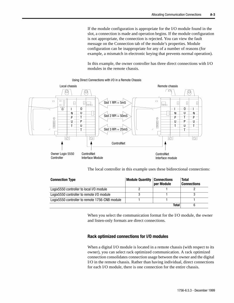
Allocating Communication Connections A-3
n).
I/O
s:
er
o its
igital ions
If the module configuration is appropriate for the I/O module found in the slot, a connection is made and operation begins. If the module configuration is not appropriate, the connection is rejected. You can view the fault message on the Connection tab of the module’s properties. Module configuration can be inappropriate for any of a number of reasons (for example, a mismatch in electronic keying that prevents normal operatio
In this example, the owner controller has three direct connections with modules in the remote chassis.
The local controller in this example uses these bidirectional connection
When you select the communication format for the I/O module, the ownand listen-only formats are direct connections.
Rack optimized connections for I/O modules
When a digital I/O module is located in a remote chassis (with respect towner), you can select rack optimized communication. A rack optimized connection consolidates connection usage between the owner and the dI/O in the remote chassis. Rather than having individual, direct connectfor each I/O module, there is one connection for the entire chassis.
Using Direct Connections with I/O in a Remote Chassis
Owner Logix 5550 ControlNet
Slot 1 RPI = 5mS
Slot 2 RPI = 50mS
Slot 3 RPI = 25mS
ControlNet
Local chassis Remote chassis
INPUT
INPUT
OUTPUT
ControlNet
INPUT
OUTPUT
Interface moduleInterface ModuleController
Connection Type Module Quantity Connections per Module
Total Connections
Logix5550 controller to local I/O module 2 1 2
Logix5550 controller to remote I/O module 3 1 3
Logix5550 controller to remote 1756-CNB module 1 1 1
Total 6
1756-6.5.3 - December 1999
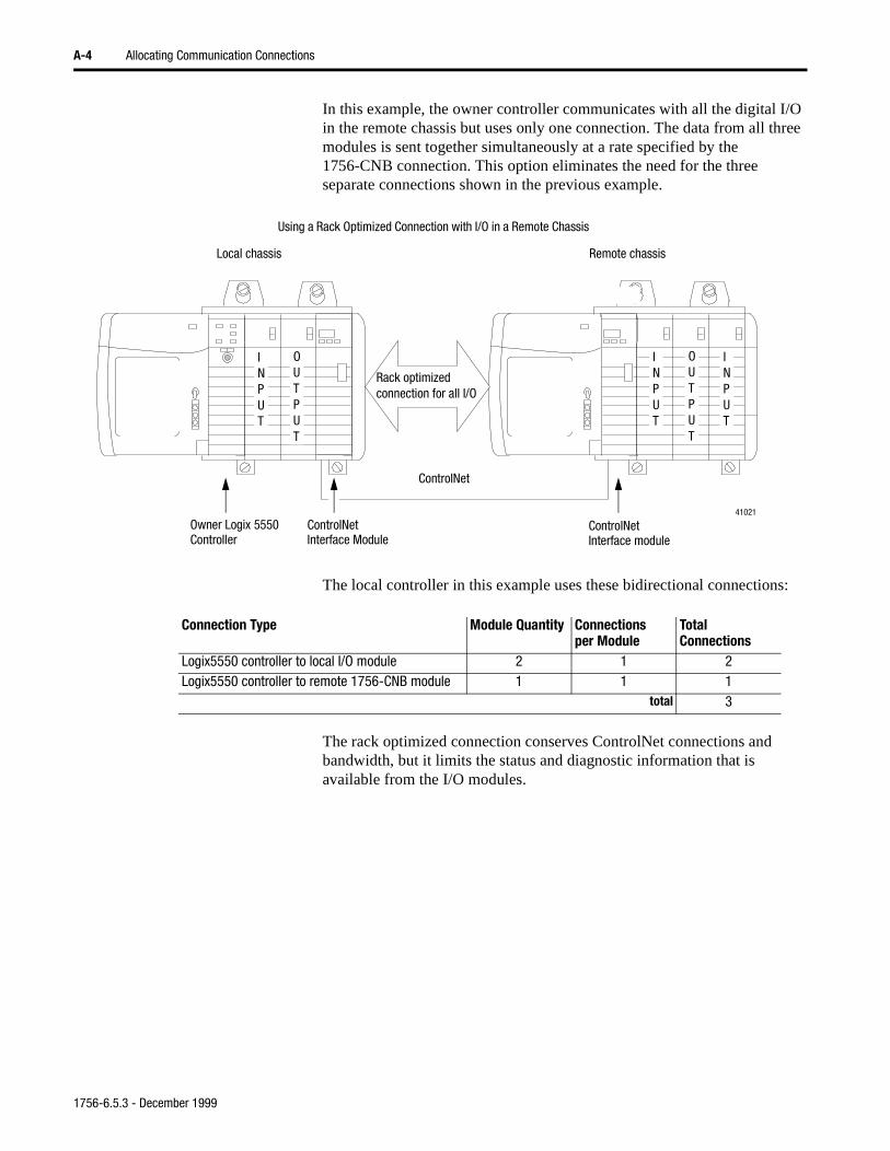
A-4 Allocating Communication Connections
In this example, the owner controller communicates with all the digital I/O in the remote chassis but uses only one connection. The data from all three modules is sent together simultaneously at a rate specified by the 1756-CNB connection. This option eliminates the need for the three separate connections shown in the previous example.
The local controller in this example uses these bidirectional connections:
The rack optimized connection conserves ControlNet connections and bandwidth, but it limits the status and diagnostic information that is available from the I/O modules.
Using a Rack Optimized Connection with I/O in a Remote Chassis
Local chassis Remote chassis
INPUT
INPUT
OUTPUT
Rack optimized connection for all I/O
ControlNet
41021
INPUT
OUTPUT
Owner Logix 5550 ControlNet ControlNetInterface moduleInterface ModuleController
Connection Type Module Quantity Connections per Module
Total Connections
Logix5550 controller to local I/O module 2 1 2Logix5550 controller to remote 1756-CNB module 1 1 1
total 3
1756-6.5.3 - December 1999
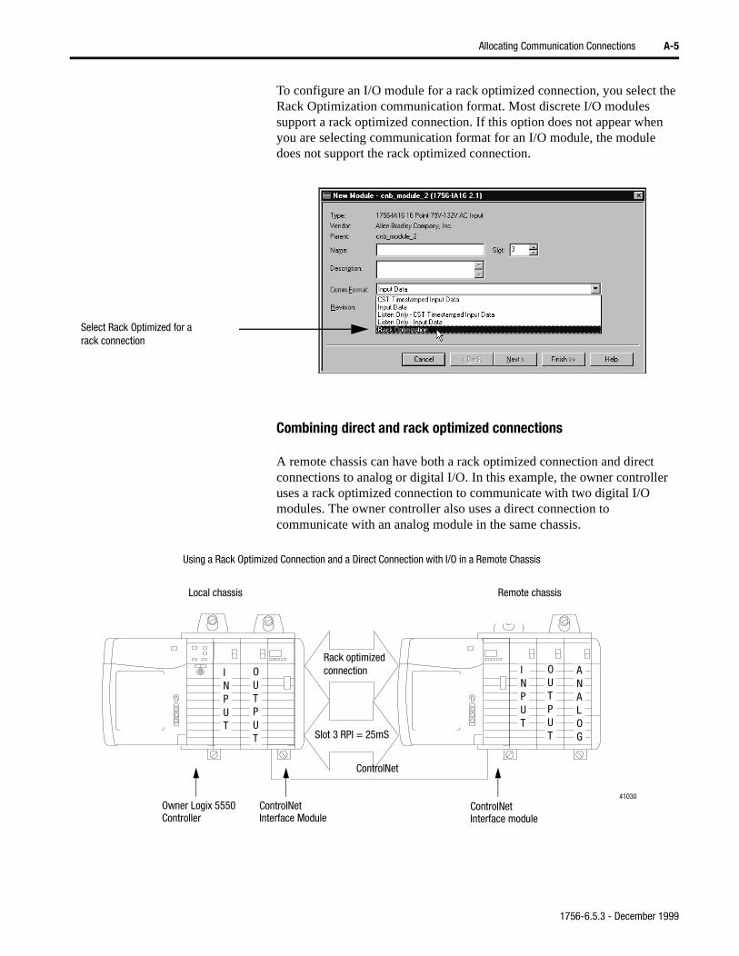
Allocating Communication Connections A-5
To configure an I/O module for a rack optimized connection, you select the Rack Optimization communication format. Most discrete I/O modules support a rack optimized connection. If this option does not appear when you are selecting communication format for an I/O module, the module does not support the rack optimized connection.
Combining direct and rack optimized connections
A remote chassis can have both a rack optimized connection and direct connections to analog or digital I/O. In this example, the owner controller uses a rack optimized connection to communicate with two digital I/O modules. The owner controller also uses a direct connection to communicate with an analog module in the same chassis.
Select Rack Optimized for a rack connection
Using a Rack Optimized Connection and a Direct Connection with I/O in a Remote Chassis
Local chassis Remote chassis
INPUT
ANALOG
OUTPUT
ControlNet
41030
Rack optimized connection
Slot 3 RPI = 25mS
INPUT
OUTPUT
Owner Logix 5550 ControlNet ControlNetInterface moduleInterface ModuleController
1756-6.5.3 - December 1999
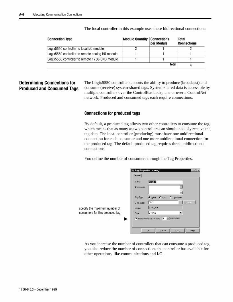
A-6 Allocating Communication Connections
The local controller in this example uses these bidirectional connections:
Determining Connections for Produced and Consumed Tags
The Logix5550 controller supports the ability to produce (broadcast) and consume (receive) system-shared tags. System-shared data is accessible by multiple controllers over the ControlBus backplane or over a ControlNet network. Produced and consumed tags each require connections.
Connections for produced tags
By default, a produced tag allows two other controllers to consume the tag, which means that as many as two controllers can simultaneously receive the tag data. The local controller (producing) must have one unidirectional connection for each consumer and one more unidirectional connection for the produced tag. The default produced tag requires three unidirectional connections.
You define the number of consumers through the Tag Properties.
As you increase the number of controllers that can consume a produced tag, you also reduce the number of connections the controller has available for other operations, like communications and I/O.
Connection Type Module Quantity Connections per Module
Total Connections
Logix5550 controller to local I/O module 2 1 2Logix5550 controller to remote analog I/O module 1 1 1Logix5550 controller to remote 1756-CNB module 1 1 1
total 4
specify the maximum number of consumers for this produced tag
1756-6.5.3 - December 1999
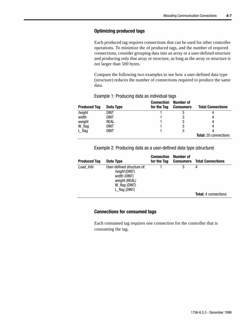
Allocating Communication Connections A-7
Optimizing produced tags
Each produced tag requires connections that can be used for other controller operations. To minimize the of produced tags, and the number of required connections, consider grouping data into an array or a user-defined structure and producing only that array or structure, as long as the array or structure is not larger than 500 bytes.
Compare the following two examples to see how a user-defined data type (structure) reduces the number of connections required to produce the same data.
Example 1: Producing data as individual tags
Example 2: Producing data as a user-defined data type (structure)
Connections for consumed tags
Each consumed tag requires one connection for the controller that is consuming the tag.
Produced Tag Data TypeConnection for the Tag
Number of Consumers Total Connections
heightwidthweightW_flagL_flag
DINTDINTREALDINTDINT
11111
33333
44444
Total: 20 connections
Produced Tag Data TypeConnection for the Tag
Number of Consumers Total Connections
Load_Info User-defined structure of:height (DINT)width (DINT)weight (REAL)W_flag (DINT)L_flag (DINT)
1 3 4
Total: 4 connections
1756-6.5.3 - December 1999
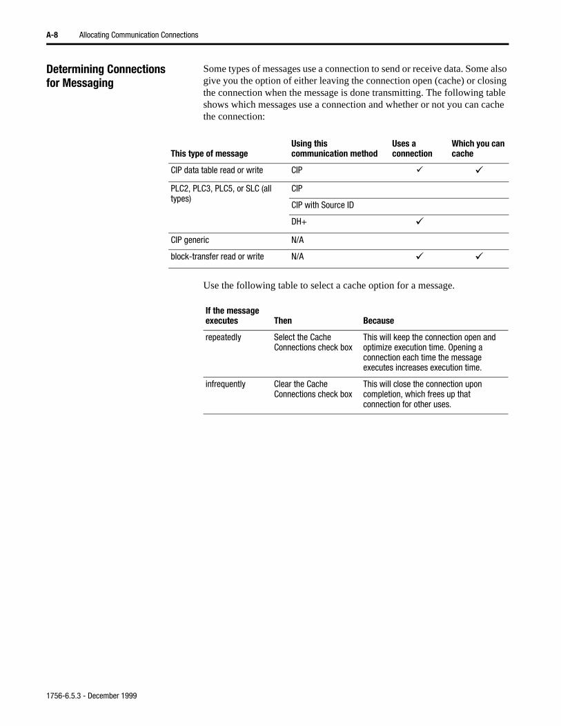
A-8 Allocating Communication Connections
Determining Connections for Messaging
Some types of messages use a connection to send or receive data. Some also give you the option of either leaving the connection open (cache) or closing the connection when the message is done transmitting. The following table shows which messages use a connection and whether or not you can cache the connection:
Use the following table to select a cache option for a message.
This type of messageUsing thiscommunication method
Uses a connection
Which you can cache
CIP data table read or write CIP á á
PLC2, PLC3, PLC5, or SLC (all types)
CIP
CIP with Source ID
DH+ á
CIP generic N/A
block-transfer read or write N/A á á
If the message executes Then Because
repeatedly Select the Cache Connections check box
This will keep the connection open and optimize execution time. Opening a connection each time the message executes increases execution time.
infrequently Clear the Cache Connections check box
This will close the connection upon completion, which frees up that connection for other uses.
1756-6.5.3 - December 1999
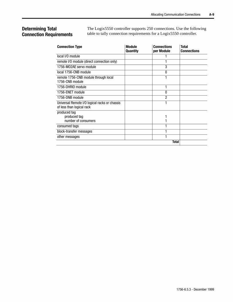
Allocating Communication Connections A-9
Determining Total Connection Requirements
The Logix5550 controller supports 250 connections. Use the following table to tally connection requirements for a Logix5550 controller.
Connection Type ModuleQuantity
Connections per Module
Total Connections
local I/O module 1remote I/O module (direct connection only) 11756-MO2AE servo module 3local 1756-CNB module 0remote 1756-CNB module through local 1756-CNB module
1
1756-DHRIO module 11756-ENET module 01756-DNB module 2Universal Remote I/O logical racks or chassisof less than logical rack
1
produced tagproduced tagnumber of consumers
11
consumed tags 1block-transfer messages 1other messages 1
Total
1756-6.5.3 - December 1999

A-10 Allocating Communication Connections
1756-6.5.3 - December 1999
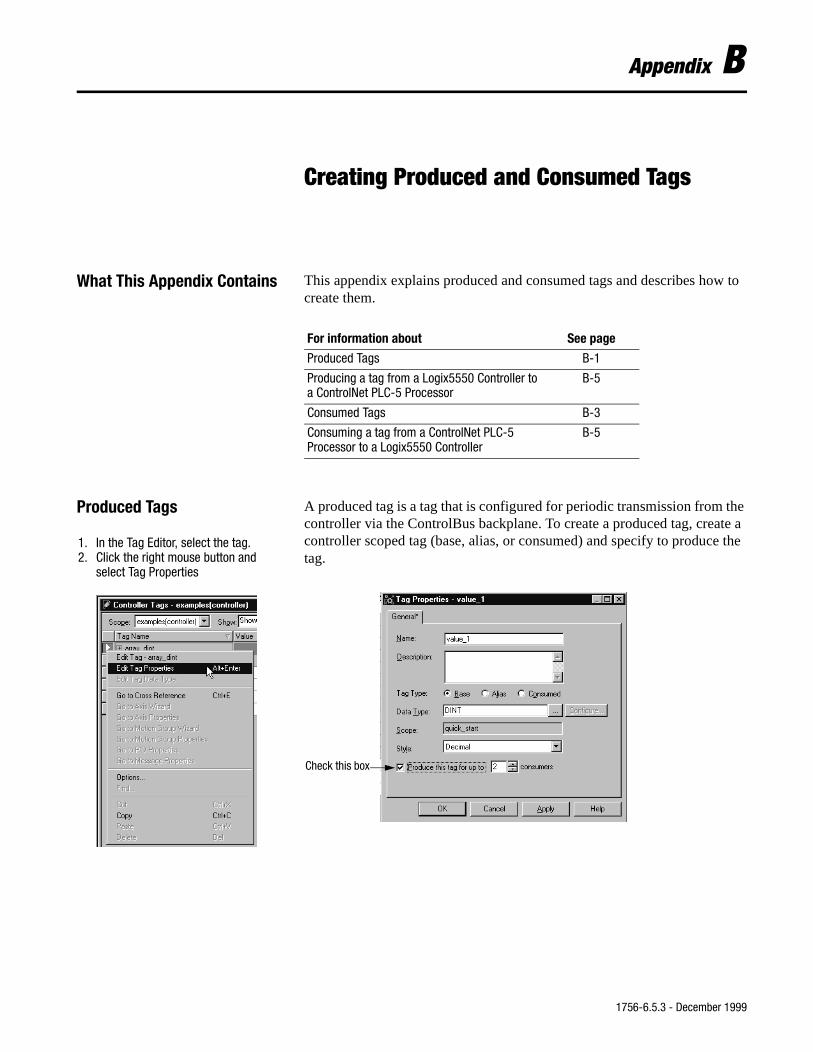
Appendix B
Creating Produced and Consumed Tags
What This Appendix Contains This appendix explains produced and consumed tags and describes how to create them.
Produced Tags A produced tag is a tag that is configured for periodic transmission from the controller via the ControlBus backplane. To create a produced tag, create a controller scoped tag (base, alias, or consumed) and specify to produce the tag.
For information about See page
Produced Tags B-1
Producing a tag from a Logix5550 Controller to a ControlNet PLC-5 Processor
B-5
Consumed Tags B-3
Consuming a tag from a ControlNet PLC-5 Processor to a Logix5550 Controller
B-5
1. In the Tag Editor, select the tag.2. Click the right mouse button and
select Tag Properties
Check this box
1756-6.5.3 - December 1999
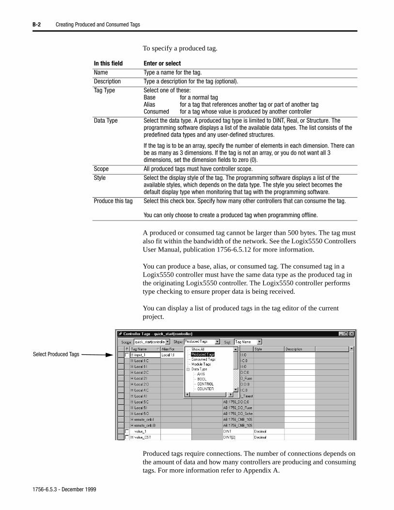
B-2 Creating Produced and Consumed Tags
To specify a produced tag.
A produced or consumed tag cannot be larger than 500 bytes. The tag must also fit within the bandwidth of the network. See the Logix5550 Controllers User Manual, publication 1756-6.5.12 for more information.
You can produce a base, alias, or consumed tag. The consumed tag in a Logix5550 controller must have the same data type as the produced tag in the originating Logix5550 controller. The Logix5550 controller performs type checking to ensure proper data is being received.
You can display a list of produced tags in the tag editor of the current project.
Produced tags require connections. The number of connections depends on the amount of data and how many controllers are producing and consuming tags. For more information refer to Appendix A.
In this field Enter or selectName Type a name for the tag.Description Type a description for the tag (optional).Tag Type Select one of these:
Base for a normal tagAlias for a tag that references another tag or part of another tagConsumed for a tag whose value is produced by another controller
Data Type Select the data type. A produced tag type is limited to DINT, Real, or Structure. The programming software displays a list of the available data types. The list consists of the predefined data types and any user-defined structures.
If the tag is to be an array, specify the number of elements in each dimension. There can be as many as 3 dimensions. If the tag is not an array, or you do not want all 3 dimensions, set the dimension fields to zero (0).
Scope All produced tags must have controller scope.Style Select the display style of the tag. The programming software displays a list of the
available styles, which depends on the data type. The style you select becomes the default display type when monitoring that tag with the programming software.
Produce this tag Select this check box. Specify how many other controllers that can consume the tag.
You can only choose to create a produced tag when programming offline.
Select Produced Tags
1756-6.5.3 - December 1999
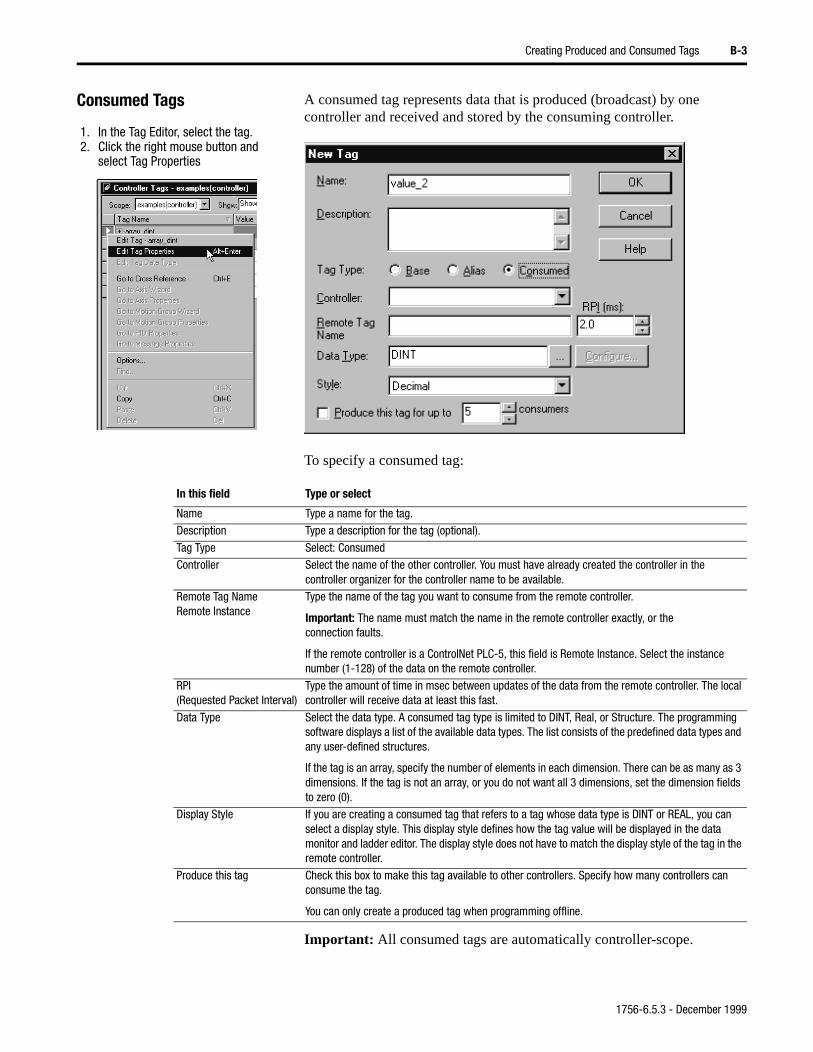
Creating Produced and Consumed Tags B-3
Consumed Tags A consumed tag represents data that is produced (broadcast) by one controller and received and stored by the consuming controller.
To specify a consumed tag:
Important: All consumed tags are automatically controller-scope.
1. In the Tag Editor, select the tag.2. Click the right mouse button and
select Tag Properties
In this field Type or select
Name Type a name for the tag.Description Type a description for the tag (optional).
Tag Type Select: ConsumedController Select the name of the other controller. You must have already created the controller in the
controller organizer for the controller name to be available.Remote Tag NameRemote Instance
Type the name of the tag you want to consume from the remote controller.
Important: The name must match the name in the remote controller exactly, or the connection faults.
If the remote controller is a ControlNet PLC-5, this field is Remote Instance. Select the instance number (1-128) of the data on the remote controller.
RPI(Requested Packet Interval)
Type the amount of time in msec between updates of the data from the remote controller. The local controller will receive data at least this fast.
Data Type Select the data type. A consumed tag type is limited to DINT, Real, or Structure. The programming software displays a list of the available data types. The list consists of the predefined data types and any user-defined structures.
If the tag is an array, specify the number of elements in each dimension. There can be as many as 3 dimensions. If the tag is not an array, or you do not want all 3 dimensions, set the dimension fields to zero (0).
Display Style If you are creating a consumed tag that refers to a tag whose data type is DINT or REAL, you can select a display style. This display style defines how the tag value will be displayed in the data monitor and ladder editor. The display style does not have to match the display style of the tag in the remote controller.
Produce this tag Check this box to make this tag available to other controllers. Specify how many controllers can consume the tag.
You can only create a produced tag when programming offline.
1756-6.5.3 - December 1999
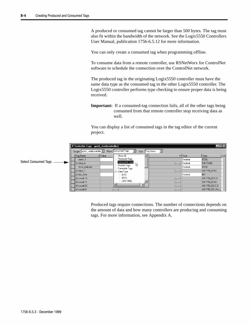
B-4 Creating Produced and Consumed Tags
A produced or consumed tag cannot be larger than 500 bytes. The tag must also fit within the bandwidth of the network. See the Logix5550 Controllers User Manual, publication 1756-6.5.12 for more information.
You can only create a consumed tag when programming offline.
To consume data from a remote controller, use RSNetWorx for ControlNet software to schedule the connection over the ControlNet network.
The produced tag in the originating Logix5550 controller must have the same data type as the consumed tag in the other Logix5550 controller. The Logix5550 controller performs type checking to ensure proper data is being received.
Important: If a consumed-tag connection fails, all of the other tags being consumed from that remote controller stop receiving data as well.
You can display a list of consumed tags in the tag editor of the current project.
Produced tags require connections. The number of connections depends on the amount of data and how many controllers are producing and consuming tags. For more information, see Appendix A.
Select Consumed Tags
1756-6.5.3 - December 1999
Creating Produced and Consumed Tags B-5
Producing a tag from a Logix5550 Controller to a ControlNet PLC-5 Processor
To produce a tag that a ControlNet PLC-5 processor can consume, follow the steps below. Refer to chapter 6 for an example.
1. Open the RSLogix5000 project.
2. Create a produced tag in the Logix5550 controller.
3. Open the RSNetWorx for ControlNet software.
4. In the ControlNet configuration for the target PLC-5 processor, create a Receive Scheduled Message.
The input size of the scheduled message must match the number of bytes in the Logix5550 tag. A produced tag in the Logix5550 controller is always a multiple of 32 bits (DINT, REAL, or structure).
5. Reschedule (save) the network in RSNetWorx for ControlNet.
The ControlNet PLC-5 controller does not perform type checking. Make sure the PLC-5 data type can correctly receive the Logix5550 produced tag to ensure proper data is being received.
Consuming a tag from a ControlNet PLC-5 Processor to a Logix5550 Controller
To consume a tag from a ControlNet PLC-5 processor, follow the steps below. Refer to chapter 8 for an example.
1. Open the RSNetWorx for ControlNet software.
2. In the ControlNet configuration for the PLC-5 processor, create a Send Scheduled Message.
Specify an output size of at least 2 (for a 32 bit double word). The size must be a multiple of 32 bit double words (specify 2, 4, 6, etc.).
3. Open the RSLogix5000 software.
4. In the controller organizer, add the PLC-5C processor to the I/O configuration.
5. Create a user-defined structure. The first member is a DINT. The second member is an INT array. The size of the INT array should match the output size entered in RSNetWorx.
6. Create a consumed tag of this user-defined type.
• Specify the instance of the Send Scheduled Data entry as the Remote Instance of the tag.
• The requested packet interval (RPI) can be as low as the network update time (NUT).
7. Reschedule (save) the network in RSNetWorx for ControlNet.
1756-6.5.3 - December 1999

B-6 Creating Produced and Consumed Tags
1756-6.5.3 - December 1999
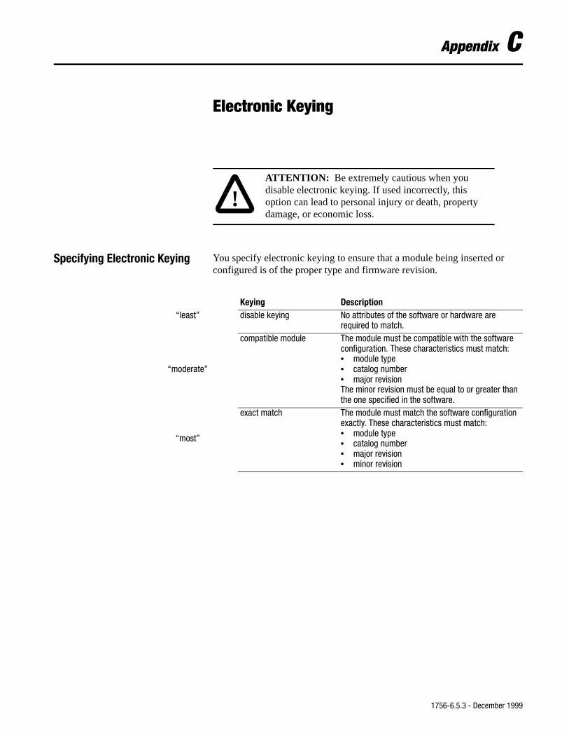
Appendix C
Electronic Keying
Specifying Electronic Keying You specify electronic keying to ensure that a module being inserted or configured is of the proper type and firmware revision.
!ATTENTION: Be extremely cautious when you disable electronic keying. If used incorrectly, this option can lead to personal injury or death, property damage, or economic loss.
Keying Description“least” disable keying No attributes of the software or hardware are
required to match.
“moderate”
compatible module The module must be compatible with the software configuration. These characteristics must match:• module type• catalog number• major revisionThe minor revision must be equal to or greater than the one specified in the software.
“most”
exact match The module must match the software configuration exactly. These characteristics must match:• module type• catalog number• major revision• minor revision
1756-6.5.3 - December 1999

C-2 Electronic Keying
1756-6.5.3 - December 1999
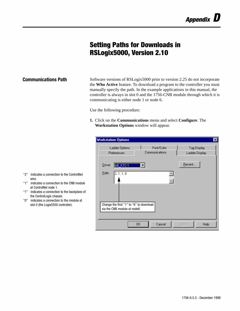
Appendix D
Setting Paths for Downloads in RSLogix5000, Version 2.10
Communications Path Software versions of RSLogix5000 prior to version 2.25 do not incorporate the Who Active feature. To download a program to the controller you must manually specify the path. In the example applications in this manual, the controller is always in slot 0 and the 1756-CNB module through which it is communicating is either node 1 or node 6.
Use the following procedure:
1. Click on the Communications menu and select Configure. The Workstation Options window will appear.
“2” indicates a connection to the ControlNet wire.
“1” indicates a connection to the CNB module at ControlNet node 1.
“1” indicates a connection to the backplane of the ControlLogix chassis.
“0” indicates a connection to the module at slot 0 (the Logix5550 controller). Change the first “1” to “6” to download
via the CNB module at node6.
1756-6.5.3 - December 1999
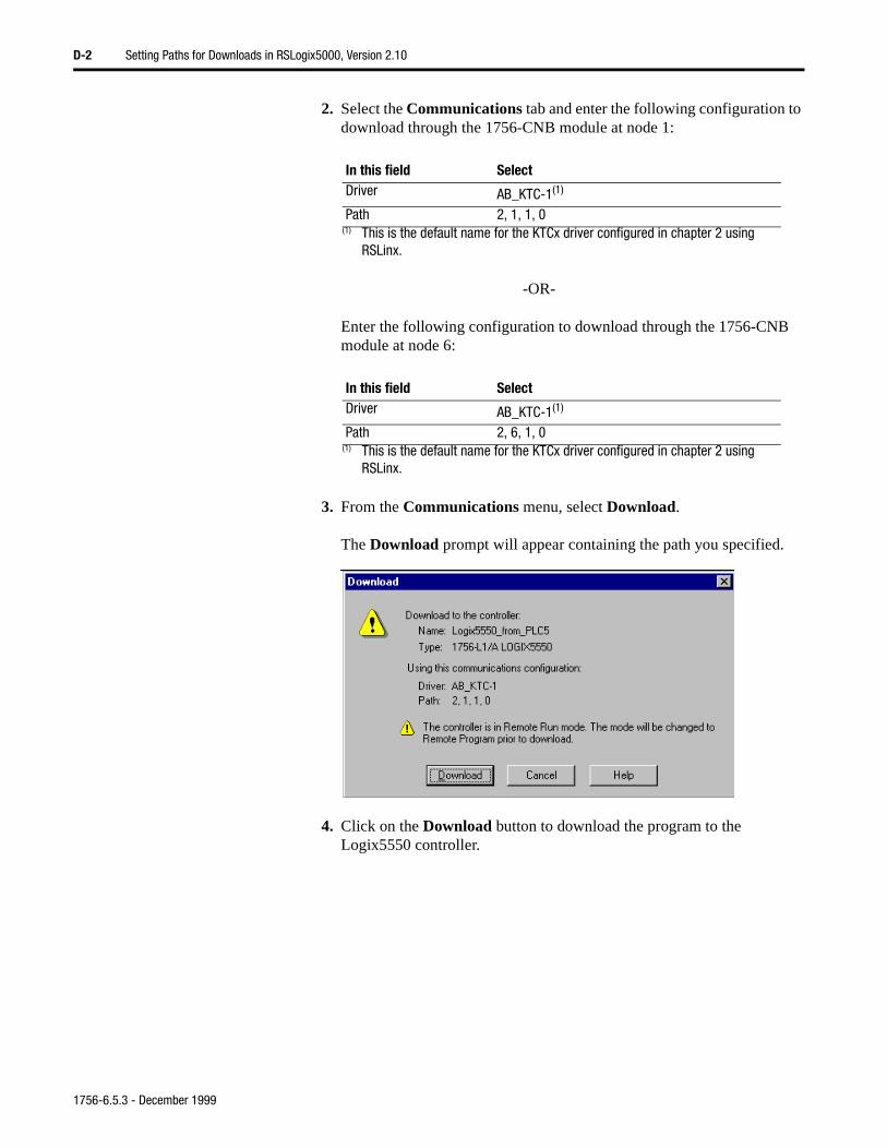
D-2 Setting Paths for Downloads in RSLogix5000, Version 2.10
2. Select the Communications tab and enter the following configuration to download through the 1756-CNB module at node 1:
-OR-
Enter the following configuration to download through the 1756-CNB module at node 6:
3. From the Communications menu, select Download.
The Download prompt will appear containing the path you specified.
4. Click on the Download button to download the program to the Logix5550 controller.
In this field SelectDriver AB_KTC-1(1)
(1) This is the default name for the KTCx driver configured in chapter 2 using RSLinx.
Path 2, 1, 1, 0
In this field SelectDriver AB_KTC-1(1)
(1) This is the default name for the KTCx driver configured in chapter 2 using RSLinx.
Path 2, 6, 1, 0
1756-6.5.3 - December 1999
Index
Aallocating communication connections
A-1 to A-9audience P-1
Ccommon techniques used in this manual
P-4configuring the 1784-KTCX15
communication interface card 2-3 to 2-4
connecting the network 2-7 to 2-8connections
allocating communication connections A-1 to A-9
combining direct and rack optimized connections A-5 to A-6
determining total connection requirements A-9
direct connections A-2 to A-3for I/O modules A-2 to A-6for messaging A-8for produced and consumed tags A-6
to A-7how ControlLogix uses connections
A-1 to A-2rack optimized A-3 to A-5
consumed tags 1-4 to 1-6creating B-1 to B-5
ControlLogix module installation 2-5 to 2-7
conventions used in this manual P-4creating produced and consumed tags
B-1 to B-5creating the system P-3customer services and support P-5
Ddirect connections A-2 to A-3
Eelectronic keying C-1, D-1example applications
about the example applications P-2expanding the network 11-1 to 11-18Logix5550 to Logix5550 scheduled
communications 4-1 to 4-20
Logix5550 to Logix5550 unscheduled message 3-1 to 3-10
Logix5550 to PLC-5C scheduled communications 6-1 to 6-18
Logix5550 to PLC-5C unscheduled message 5-1 to 5-8
PLC-5C to Logix5550 scheduled communications 8-1 to 8-23
PLC-5C to Logix5550 unscheduled message 7-1 to 7-11
PLC-5C to PLC-5C unscheduled message 9-1 to 9-8
scheduled I/O communications 10-1 to 10-18
expanding the network 11-1 to 11-18about the example application 11-1add remote 1756-CNB to I/O
configuration 11-3 to 11-5add remote analog I/O to
configuration 11-5 to 11-9adding 1756-CNB modules to
expand the network 11-17 to 11-18
create the example application 11-2 to 11-11
download the program 11-10 to 11-11
edit the controller tags 11-9 to 11-10modify the ladder logic program
11-10schedule the network 11-11 to 11-15set up the example application 11-2test the example application 11-16
Ffinding more information P-5
Iinstalling the ControlNet network 2-1 to
2-10connecting the network 2-7 to 2-8ControlLogix modules 2-5 to 2-7PLC-5 processor 2-91784-KTCX15 communication
interface card 2-2 to 2-4
Llocal product support P-5
1756-6.5.3 - December 1999
I-2
Logix5550 to Logix5550 scheduled communications 4-1 to 4-20
create consumer tags 4-12 to 4-13create producer tags 4-3create the producer application 4-2
to 4-6create the producer program 4-5download to the consumer 4-15download to the producer 4-5 to 4-6set up the example application 4-1test the communications 4-20
Logix5550 to Logix5550 unscheduled message 3-1 to 3-10
about the example application 3-1create controller tags 3-3, 3-7 to 3-8create the example application 3-2 to
3-6create the ladder program 3-4 to 3-5download the message program 3-6download the test program 3-9set up the example application 3-1test the example application 3-6 to
3-10Logix5550 to PLC-5C scheduled
communications 6-1 to 6-18about the example application 6-1configure PLC-5C 6-11 to 6-14create producer ladder program 6-5create producer tags 6-3create the producer application 6-2
to 6-6download the program 6-6schedule the network 6-7 to 6-14set up the example application 6-1test the communications 6-14 to 6-18test the example application 6-18
Logix5550 to PLC-5C unscheduled message 5-1 to 5-8
about the example application 5-1create controller tags 5-3 to 5-4create the example application 5-2 to
5-6create the ladder program 5-4 to 5-6download the program 5-6set up the example application 5-1test the example application 5-7 to
5-8
Mmaking comments P-6
mapping PLC-5C file to Logix5550 tag 7-9
messagingconnections A-8
MultiHop 7-3
Ppaths for downloads D-2PLC-5 processor installation 2-9PLC-5 terminology 1-4PLC-5C to Logix5550 scheduled
communications 8-1 to 8-23about the example application 8-1add local CNB to I/O configuration
8-10 to 8-11add producer to I/O configuration
8-10 to 8-13create consumer tags 8-13 to 8-17create the example application 8-18
to 8-21create the PLC-5C program 8-19download the Logix5550 program
8-17download the PLC-5C program 8-19
to 8-20set up the example application 8-1test the example application 8-23
PLC-5C to Logix5550 unscheduled message 7-1 to 7-11
about the example application 7-1create controller tags 7-8create the example application 7-2 to
7-6create the PLC-5C program 7-3 to
7-4download the Logix5550 program
7-10download the PLC-5C program 7-5
to 7-6map PLC-5C file to Logix5550 tag
7-9set up the example application 7-1test the example application 7-7 to
7-11PLC-5C to PLC-5C unscheduled
message 9-1 to 9-8about the example application 9-1create the example application 9-2 to
9-6create the ladder program 9-3 to 9-4download the program 9-5 to 9-6
1756-6.5.3 - December 1999
I-3
set up the example application 9-1test the example application 9-6 to
9-8produced tags 1-4 to 1-6
creating B-1 to B-5optimizing A-7
producer/consumer model 1-4 to 1-6
Rrack optimized connections A-3 to A-5related publications P-5RSNetWorx for ControlNet 4-16 to
4-19, 6-7 to 6-14, 8-2 to 8-8, 10-13 to 10-17, 11-11 to 11-15
Sscheduled communications
add producer to consumer I/O configuration 4-6 to 4-12
add remote CNB to I/O configuration 4-9 to 4-11
add remote controller to I/O configuration 4-11 to 4-12
Logix5550 to Logix5550 4-1 to 4-20scheduled I/O communications 10-1 to
10-18about the example application 10-1add local CNB to I/O configuration
10-3 to 10-4add remote CNB to I/O configuration
10-4 to 10-7add remote digital input module 10-7
to 10-9add remote digital output module
10-7 to 10-10
add remote I/O modules to configuration 10-7 to 10-11
control of 1-6create the example application 10-1
to 10-13create the ladder program 10-12download the program 10-12 to
10-13edit controller tags 10-11schedule the network 10-13 to 10-17set up the example application 10-2test the example application 10-18
1784-KTCX15 installation 2-2 to 2-4status indicator and display, module 12-1
to 12-3status indicators, network 12-3 to 12-4suggestions P-6support P-5system components P-3
Ttags
see consumed tags, produced tagstechnical product assistance P-6troubleshooting 12-1 to 12-4
status indicator and display, module 12-1 to 12-3
status indicators, network 12-3 to 12-4
Uusing this manual P-1 to P-6
Wwhere to go for questions P-6
1756-6.5.3 - December 1999

I-4
1756-6.5.3 - December 1999
Allen-BradleyPublication Problem ReportIf you find a problem with our documentation, please complete and return this form.
Pub. Title/Type
ControlLogix ControlNet Interface Module/User Manual
Cat. No. 1756-CNB, -CNBR Pub. No. 1756-6.5.3 Pub. Date December 1999 Part No. 955127-21
Check Problem(s) Type: Describe Problem(s) Internal Use Only
Technical Accuracy text illustration
Completeness procedure/step illustration definition info in manual
What information is example guideline feature (accessibility)
explanation other info not in
Clarity
What is unclear?
Sequence
What is not in the right
Other Comments
Use back for more
Your Name Location/Phone
Return to: Marketing Communications, Allen-Bradley., 1 Allen-Bradley Drive, Mayfield Hts., OH 44124-6118Phone:(440) 646-3176FAX:(440) 646-4320
Publication 1756-6.5.3- December 1999 PN 955127-21
Other
PLEASE FOLD HERE
NO POSTAGE NECESSARY IF MAILED
IN THE UNITED STATES
BUSINESS REPLY FIRST-CLASS MAIL PERMIT NO. 18235
POSTAGE WILL BE PAID BY THE
1 ALLEN-BRADLEY DRMAYFIELD HEIGHTS OH 44124-9705
PLEASE FASTEN HERE (DO NOT
PL
EA
SE

1756-6.5.3 - December 1999

Publication 1756-6.5.3 - December 1999 PN 955127-21©1999 Rockwell International Corporation. Printed in the U.S.A.
Back Cover

Allen-BradleyControlLogix ControlNet Interface M
oduleUser M
anual