alfalfa production manual - agriculture...
TRANSCRIPT
ALFALFAPRODUCTIONMANUAL
USING SUBSURFACE DRIP IRRIGATION
N E T A F I M U S A
WWW.NETAFIMUSA.COM

2 • NETAFIM USA ALFALFA PRODUCTION MANUAL
NETAFIM USA ALFALFA PRODUCTION MANUAL • 3
TABLE OF CONTENTSALFALFA PRODUCTION USING SUBSURFACE DRIP IRRIGATION Overview............................................................... 5Drip System Components ...................................6SDI Layout and Design for Alfalfa ...................10Field Preparation ................................................12Soil Fertility..........................................................12Alfalfa Stand Establishment .............................13SDI System Start-Up..........................................15System Pressure and Flow Rate .....................15Monitoring Your Drip System ...........................15Irrigation Scheduling .........................................17Fertilization of Alfalfa ........................................25Essential Plant Nutrients .................................25Correcting Nutrient Deficiencies ...................26Fertigation ..........................................................29Drip System Maintenance ...............................31Chlorine Injection ...............................................35Acid Injection .....................................................37Iron Control System ..........................................39
RODENT MANAGEMENT STRATEGIESIntroduction ........................................................41Management Plan .............................................41Habitat Modification ..........................................41Proper DripLine Installation Practices to Reduce Rodent Damage ..................................42Trapping and Removal ......................................42Biological Controls ............................................43Protec-T™ ..........................................................44Extermination .....................................................44Rodent Management Action Plan ...................45Rodent Management References ...................46Pocket Gopher Management Supplies ..........47

4 • NETAFIM USA ALFALFA PRODUCTION MANUAL
NETAFIM USA ALFALFA PRODUCTION MANUAL • 5
OVERVIEWAlfalfa is a deep-rooted perennial forage crop that is mainly planted for hay production or grazing. When compared to other forage crops, alfalfa has a very high yield potential and responds very well to subsurface drip irrigation (SDI). A key benefit of irrigating alfalfa with SDI is the ability to irrigate during and immediately following harvest allowing for rapid re-growth which can result in more cuts and higher yields.
Subsurface drip irrigation on alfalfa is used in a number of areas in the arid west. Experience on medium textured soils has shown that driplines with 24 inch dripper spacing, rows positioned 40-60 inches apart and buried 12 to 18 inches deep result in very even growth over the total soil surface area. Dripper flow rate and spacing are determined by the soil properties and water availability. The common method for the scheduling of irrigation is based on crop water use. Commercial yields of up to 15 tons dry material per acre have been achieved. These yields are the same or better than surface irrigation methods. SDI can be managed to reduce water usage and runoff by closely matching crop requirements with irrigation application rates.
Subsurface drip irrigation is a management tool that allows precise control over the root zone environment of your alfalfa crop. This control can be used to increase yields, reduce water needs and runoff or better manage crop quality. But with any management tool there are trade-offs. Many growers find they can obtain one to three extra harvests per year using the same amount of water as with their previous irrigation system. Others can reduce water consumption but do not experience greater harvests. The intent of this manual is to describe the layout, installation, operation and maintenance of a SDI system on alfalfa. It should also serve as a guide to help in the decision-making process to convert to drip technology as well as how to manage this technology to obtain the desired results.
WHY SUBSURFACE DRIP IRRIGATION ON ALFALFA?Of the common agronomic crops, alfalfa consumes the largest amount of water. Its consumptive use can exceed 46 inches of water per year. The main reason growers are interested in using drip irrigation on alfalfa comes from the desire to better manage this increasingly expensive crop input.
ADVANTAGES OF SUBSURFACE DRIP IRRIGATION ON ALFALFA
• More rapid re-growth following harvest. Alfalfa irrigated with SDI can be watered immediately following and even during harvest. The crop re-grows faster which can result in one or more additional harvests per year.
• Better fertilizer management. Application of fertilizer directly to the root zone results in a healthier crop which may remain productive longer and yield higher quality hay.
• Runoff from the field can be more easily managed and significantly reduced by employing SDI.
• In general, drip systems require less irrigation labor than flood irrigated crops. Experience has shown a 50% reduction in irrigation labor is possible.
• SDI allows for better stand management. Ground compaction and weeds are reduced because the soil surface is kept dry. SDI can be managed to produce healthier root systems improving stand longevity.
CRITICAL ASPECTS THAT NEED TO BE CONSIDERED WHEN CONVERTING TO SDI
• Although the establishment of Alfalfa is sometimes achieved with the drip system, it is recommended that sprinklers or flood irrigation be used for soil preparation and emergence.
• SDI system requires consistent, periodic maintenance to ensure it is performing to specifications.
• SDI is more than a watering device it is a root-zone management tool. To get the most out of it requires careful records of crop and system activity.
• SDI systems have been in continuous use for over 20 years. Given the potential long life and cost of the system crop rotation and cultivation practices such as deep cultivation and re-establishment must be considered.
• Rodents not only reduce alfalfa yields but can devastate a drip system. A rodent management plan must be implemented. We provide an outline for such a plan in this manual.
6 • NETAFIM USA ALFALFA PRODUCTION MANUAL
DRIP SYSTEM COMPONENTS
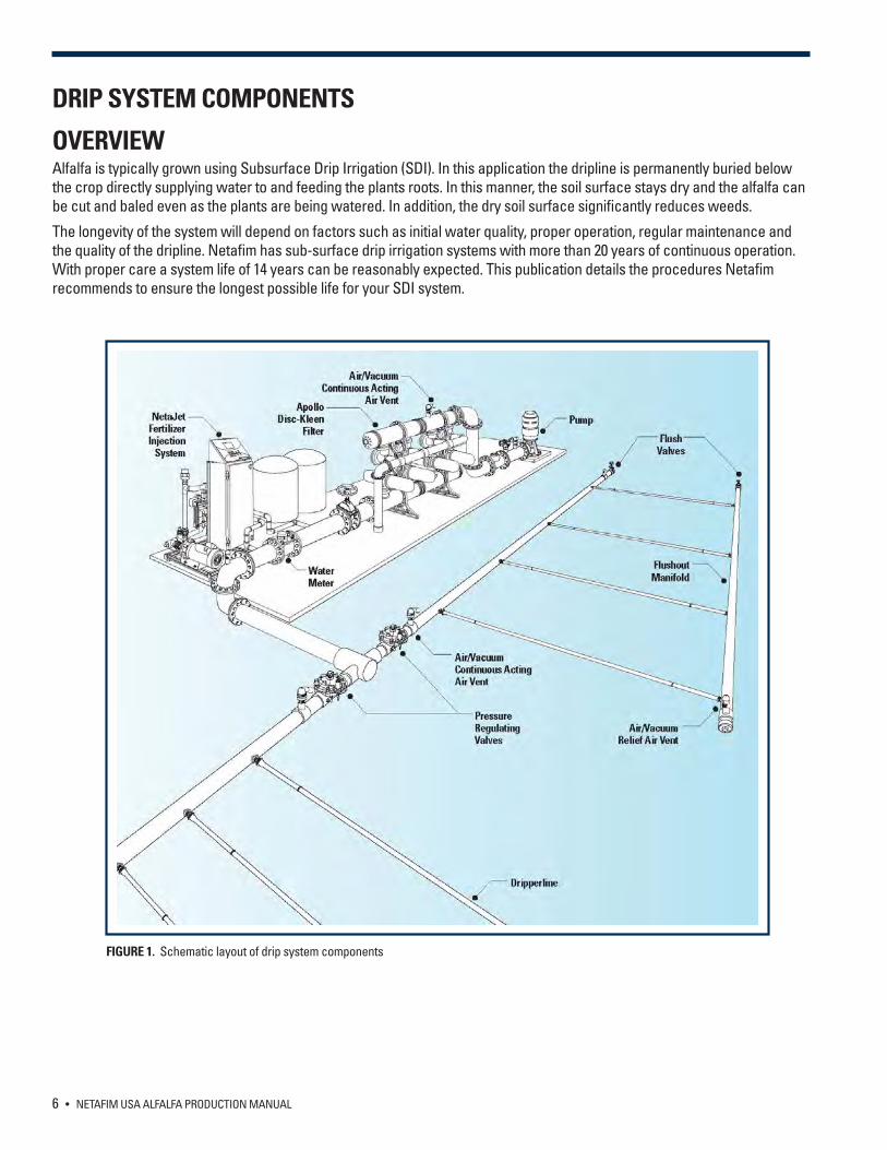
OVERVIEWAlfalfa is typically grown using Subsurface Drip Irrigation (SDI). In this application the dripline is permanently buried below the crop directly supplying water to and feeding the plants roots. In this manner, the soil surface stays dry and the alfalfa can be cut and baled even as the plants are being watered. In addition, the dry soil surface significantly reduces weeds.
The longevity of the system will depend on factors such as initial water quality, proper operation, regular maintenance and the quality of the dripline. Netafim has sub-surface drip irrigation systems with more than 20 years of continuous operation. With proper care a system life of 14 years can be reasonably expected. This publication details the procedures Netafim recommends to ensure the longest possible life for your SDI system.
FIGURE 1. Schematic layout of drip system components
NETAFIM USA ALFALFA PRODUCTION MANUAL • 7
WATERThe chemical composition of the irrigation water to be used must be analyzed in a certified laboratory to determine its suitability for drip irrigated alfalfa production. High levels of chlorine and sodium can be harmful to crop production and possibly decrease the maximum yield potential. When irrigating, the soil will be influenced by the chemical composition of the irrigation water. Build-up of sodium can lead to poor permeability affecting the distribution of water within the soil. Iron, manganese and the formation of lime or gypsum can potentially damage the emitters. These elements can be controlled through proper water treatment. System design may be affected by the need for water treatment. Maintenance procedures
may also need to be adjusted for specific water conditions.
BASIC SYSTEM LAYOUTFigure 1 on the previous page is a schematic layout of the components which make up an SDI system:
• Dripline - the heart of the system (depending upon the field conditions) can be either pressure compensating (hilly terrain) or non-pressure compensating (flat terrain).
• Filters (typically a disc or media filtration system) is the best choice to protect the dripline. • Fertilizer Injector – injects fertilizer chemicals into the system for maximum crop performance and to maintain the
dripline over the long term.• Pipeline headers, control and air release vents complete the system.
Our intent is not to describe the process of system design in detail. Your Netafim USA Dealer is trained to design and install quality SDI systems. It is important to understand how the system is put together and why certain design elements are specified.
DRIPLINE SPECIFICATIONSThe following dripline recommendations are meant as guidelines only - soil type, topography and water quality will affect the final design. Your Netafim USA Dealer is familiar with the local conditions and will recommend a dripline that is appropriate for your area. The dripline should be installed with a GPS where possible so that its position can be determined as necessary. Depending upon local conditions the dripline can either have pressure compensating (Netafim DripNet PC or UniRam) or non-compensating drippers (Netafim Typhoon or Streamline). Factors such as length of run, topography, zone size and water quality play an important role in choosing the right dripper. Regardless of the type of dripper used there are several basic guidelines to follow:
1. The distance between driplines is determined by the crop. For alfalfa crops with rows every 40 inches the typical spacing between rows of driplines is 80 inches, with the dripline located in the furrow and one dripline in every other row. With this layout one dripline irrigates two rows with one irrigated row followed by a dry row. This arrangement has implications for measuring the moisture content of the soil. The measurement should never be taken in the dry row. Some growers have been increasing the density of their plantings by moving to 20 inches rows and in this case the dripline is placed on 40 inches centers. In all cases the water application rate is set by design to meet the crop needs given the water availability.
2. Driplines are generally buried at a depth of 12 inches to 18 inches. The crop being grown, the soil texture and the presence of rodents are the main considerations for determining the burial depth of the dripline. Sandy soils generally require a more shallow burial. In areas with a large rodent population, deeper burial of the dripline is less likely to cross paths with rodent’s teeth. In general, rodents are not fond of sandy soil so the shallower depth is not a concern. However, deeper placement may make it difficult to germinate the crop with the drip system unless there is sufficient residual moisture in the soil. The following should be taken into consideration when designing the SDI system:
• The distance between drippers and the dripper flow rate - selected to achieve the appropriate application rate given the water availability.
• Dripline wall thickness - 13 to 35 mil is usually recommended, with 15 to 25 mil most commonly used.
8 • NETAFIM USA ALFALFA PRODUCTION MANUAL
PUMP REQUIREMENTSThe volume output of the pumping station dictates the amount of area that can be irrigated. A simple formula has been derived converting the maximum required evapotranspiration rate (ET) in inches of water per day per acre into gallons per minute per acre.
ET (inches/day/acre) *18.86 (conversion factor) = GPM/acre
Using this formula - an ET of 0.25 inches per 24 hours per acre would require 4.72 GPM/acre.
This calculation is for a pump running 24 hours. More commonly as a safety factor, systems are sized for 20 hours of operation. To accomplish this use the following formula:
24 (hours in a day)/ (number of hours desired for irrigation) X (GPM/acre)24/20 X 4.72 = 5.66 GPM/acre
On flat land the pressure output required of the pump stations is mainly dictated by the flushing requirements of the filters and pipes. On hilly terrain the pressure required to lift water to the highest point must also be considered. Most automatic filters require a minimum of 30 psi to self-clean properly. This is generally the pump’s minimum operating pressure to operate a drip system.
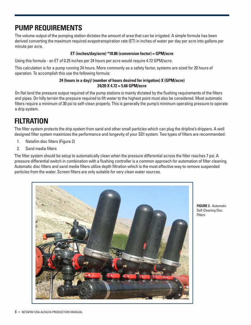
FILTRATIONThe filter system protects the drip system from sand and other small particles which can plug the dripline’s drippers. A well designed filter system maximizes the performance and longevity of your SDI system. Two types of filters are recommended:
1. Netafim disc filters (Figure 2)
2. Sand media filters
The filter system should be setup to automatically clean when the pressure differential across the filter reaches 7 psi. A pressure differential switch in combination with a flushing controller is a common approach for automation of filter cleaning. Automatic disc filters and sand media filters utilize depth filtration which is the most effective way to remove suspended particles from the water. Screen filters are only suitable for very clean water sources.
FIGURE 2. Automatic Self-Cleaning Disc Filters
NETAFIM USA ALFALFA PRODUCTION MANUAL • 9
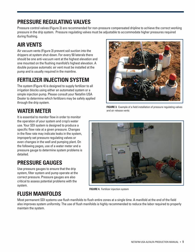
PRESSURE REGULATING VALVESPressure control valves (Figure 3) are recommended for non-pressure compensated dripline to achieve the correct working pressure in the drip system. Pressure regulating valves must be adjustable to accommodate higher pressures required during flushing.
AIR VENTSAir vacuum vents (Figure 3) prevent soil suction into the drippers at system shut-down. For every 50 laterals there should be one anti-vacuum vent at the highest elevation and one mounted on the flushing manifold’s highest elevation. A double purpose automatic air vent must be installed at the pump and is usually required in the mainline.
FERTILIZER INJECTION SYSTEM The system (Figure 4) is designed to supply fertilizer to all irrigation blocks using either an automated system or a simple injection pump. Please consult your Netafim USA Dealer to determine which fertilizers may be safely applied through the drip system.
WATER METERIt is essential to monitor flow in order to monitor the operation of your system and crop’s water use. Your SDI system is designed to produce a specific flow rate at a given pressure. Changes in the flow rate may indicate leaks in the system, improperly set pressure regulating valves or even changes in the well and pumping plant. On the following pages, use of a water meter and a pressure gauge to determine system problems is detailed.
PRESSURE GAUGESUse pressure gauges to ensure that the drip system, filter system and pump operate at the correct pressure. Pressure gauges are also critical to assess potential problems with the system.
FLUSH MANIFOLDSMost permanent SDI systems use flush manifolds to flush entire zones at a single time. A manifold at the end of the field also improves system uniformity. The use of flush manifolds is highly recommended to reduce the labor required to properly maintain the system.
FIGURE 3. Example of a field installation of pressure regulating valves and air release vents
FIGURE 4. Fertilizer injection system
10 • NETAFIM USA ALFALFA PRODUCTION MANUAL
TYPICAL SYSTEM LAYOUTA typical SDI system for alfalfa will have the dripline rows spaced 40 inches apart, buried at a depth of 12 to 18 inches. The 40 inch spacing between the rows will result in even watering and a uniform stand in most soils. The 16 inch planting depth adequately supply water and nutrients to deep rooted alfalfa while keeping the soil surface dry allowing equipment to work the fields even during watering. The 16 inch depth is also below the active region of most gophers helping to reduce rodent damage to the dripline.
At a given row spacing, the flow out of each dripper and the spacing between drippers will determine the application rate. The application rate desired is dependent on water requirements, water availability and cultural practices. A common system may use 0.16 GPH Typhoon emitters spaced 24 inches apart. This will give an application rate of 0.038 inches/hour or 0.91 inches in a 24 hour period. Factors that affect dripline spacing, emitter flow rate and spacing, and dripline depth of placement include soil type, cropping system and crop rotation.
SDI LAYOUT AND DESIGN FOR ALFALFA
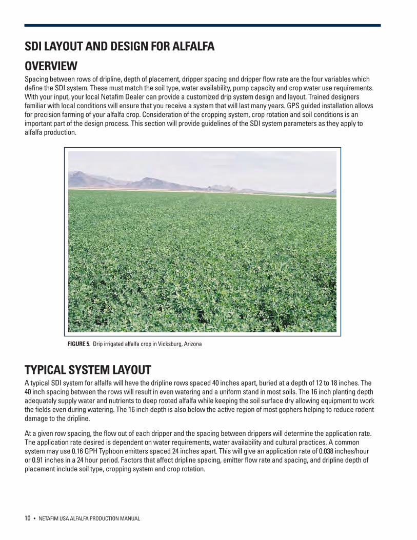
OVERVIEWSpacing between rows of dripline, depth of placement, dripper spacing and dripper flow rate are the four variables which define the SDI system. These must match the soil type, water availability, pump capacity and crop water use requirements. With your input, your local Netafim Dealer can provide a customized drip system design and layout. Trained designers familiar with local conditions will ensure that you receive a system that will last many years. GPS guided installation allows for precision farming of your alfalfa crop. Consideration of the cropping system, crop rotation and soil conditions is an important part of the design process. This section will provide guidelines of the SDI system parameters as they apply to alfalfa production.
FIGURE 5. Drip irrigated alfalfa crop in Vicksburg, Arizona
NETAFIM USA ALFALFA PRODUCTION MANUAL • 11
DRIPLINE SPACINGThe main consideration for dripline spacing is uniformity of application. Both experimental results and practical experience has shown that a 40 inch row spacing between driplines gives excellent crop uniformity and yields in most soils. To reduce system cost it is common to try to widen this spacing. It is typical at wider spacing to see bands of better performing plants under the driplines. Early results suggest that yields can be good under these conditions but it is not known if they are as good as the 40 inch spaced system. Please realize that wider spacing will require closer dripper spacing and possibly higher dripper flow rates which may exceed the infiltration rate of heavier soils. A conservative, closer, row spacing is advisable for those new to drip irrigation on alfalfa.
Soil type is the main determinant of the optimum as well as the maximum allowable spacing between driplines. Lateral distribution takes place in the capillary soil pores and is influenced by soil texture, clay, silt and fine sand fraction. Soils with more than 10% clay or silt and a high fine sand fraction have a width to depth water distribution ratio of 1.5 or larger and are therefore ideal for SDI at 40 inch spacing between driplines. In soils with less than 10% clay that has medium to coarse sand, it may be necessary to install the driplines closer to each other
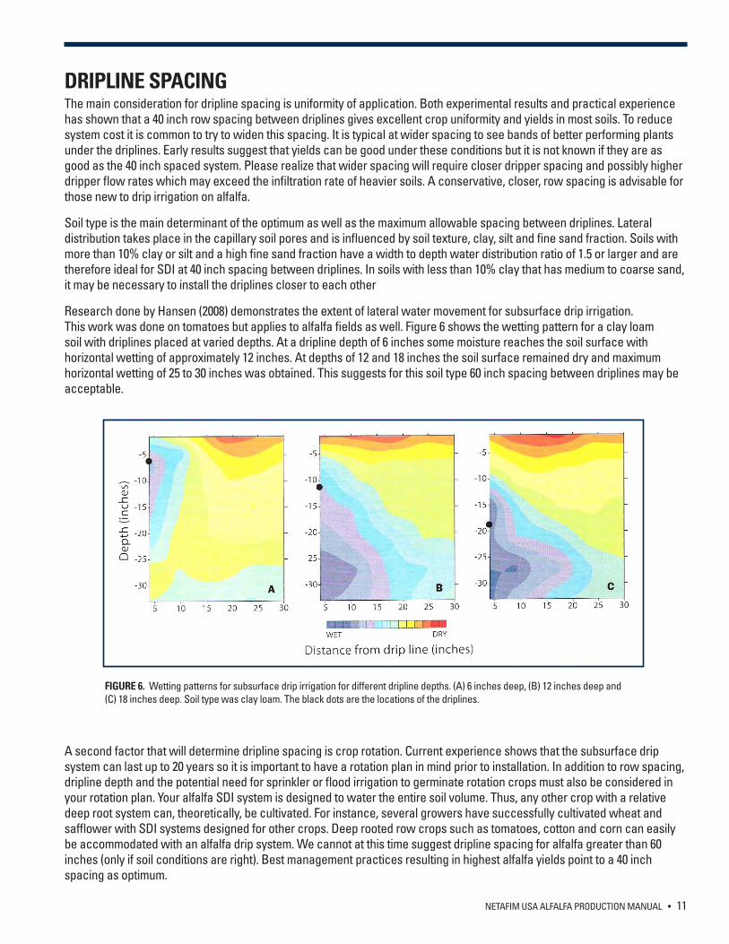
Research done by Hansen (2008) demonstrates the extent of lateral water movement for subsurface drip irrigation. This work was done on tomatoes but applies to alfalfa fields as well. Figure 6 shows the wetting pattern for a clay loam soil with driplines placed at varied depths. At a dripline depth of 6 inches some moisture reaches the soil surface with horizontal wetting of approximately 12 inches. At depths of 12 and 18 inches the soil surface remained dry and maximum horizontal wetting of 25 to 30 inches was obtained. This suggests for this soil type 60 inch spacing between driplines may be acceptable.
A second factor that will determine dripline spacing is crop rotation. Current experience shows that the subsurface drip system can last up to 20 years so it is important to have a rotation plan in mind prior to installation. In addition to row spacing, dripline depth and the potential need for sprinkler or flood irrigation to germinate rotation crops must also be considered in your rotation plan. Your alfalfa SDI system is designed to water the entire soil volume. Thus, any other crop with a relative deep root system can, theoretically, be cultivated. For instance, several growers have successfully cultivated wheat and safflower with SDI systems designed for other crops. Deep rooted row crops such as tomatoes, cotton and corn can easily be accommodated with an alfalfa drip system. We cannot at this time suggest dripline spacing for alfalfa greater than 60 inches (only if soil conditions are right). Best management practices resulting in highest alfalfa yields point to a 40 inch spacing as optimum.
FIGURE 6. Wetting patterns for subsurface drip irrigation for different dripline depths. (A) 6 inches deep, (B) 12 inches deep and (C) 18 inches deep. Soil type was clay loam. The black dots are the locations of the driplines.
12 • NETAFIM USA ALFALFA PRODUCTION MANUAL
DRIPLINE DEPTHIt is possible to place the dripline in an alfalfa field at any depth but there is little reason to place it shallower than 12 inches. The ability to irrigate immediately following or even during harvest is an important factor in the rapid re-growth and potentially higher yields of drip irrigated alfalfa. Dripline placed at 12 inches or deeper results in little moisture reaching the soil surface so equipment may be run on the field even during irrigation (see Hansen extent of lateral water movement on page 11). A shallow dripline will result in a wet surface which limits the entrance of equipment and encourages weed growth. In areas with severe rodent pressure dripline placement at a depth of 15 to even 24 inches will help reduce rodent damage - below the depth of the majority of gopher activity.
Recent feedback concerning subsurface drip irrigation shows that it leads to less soil compaction. Alfalfa has a strong root system, which lessens soil compaction or the necessity of follow-up deep cultivations. It is not foreseen that follow-up soil preparation for rotation crops needs to be deeper than 10 inches. Still if the system is installed using GPS rotation crops can be easily planted relative to the dripline and deep cultivations can be accomplished between the driplines.
DRIPPER SPACING AND FLOW RATEDripper spacing and flow rate along with row spacing determine the water application rate. These are designed to supply adequate water to satisfy the peak water use for your crop (ETc) usually expressed as inches/day. In the U.S. peak ETc usually occurs in July and ranges from 0.25 inches/day to over 0.5 inches per day. The precise peak water use depends upon the climate in your specific area and can be obtained from your local extension service. If you have poor quality water or soil, a leaching factor needs to be added to the system so that the additional water is available as needed. The section on irrigation and scheduling include more information on ET.
FIELD PREPARATIONDrip systems are typically installed on fields intended for new plantings. It is possible to install an SDI system on an existing alfalfa plot but the plant damage probably does not justify this approach. The SDI system can be expected to last 20 years. In addition, given proper care it is possible that the economic yields of your alfalfa crop can be maintained for 7 or more years. It is necessary to consider this extended life when preparing the soil.
The success of drip irrigation on alfalfa is dependent on sufficient rooting depth. A site should provide a minimum of 3 feet of unrestricted rooting depth. This can only be achieved by removing all root impeding soil layers through soil tillage. If the expectation is for a long-lived crop, then care must be taken during the soil preparation phase. The SDI system is not just a watering tool but it also allows for fertilization over the course of the crop. This is critical to maintaining economic yields over an extended period of time. Still the soil should be properly amended at the time of initial land preparation. Soil samples should be taken and analyzed before establishment to determine what chemical ameliorations are required.
Alfalfa performs best when the soil is in a pH range from 6.3 to 7.5. Soils with a pH of 6.0 or lower must be limed. Soils with a pH above 8.2 indicate excess sodium and must be reclaimed. Excess salts in your soil or water can significantly reduce yield. Salinity levels above 3.4 mmho/cm are the threshold above which yields are reduced. In high salinity areas it is necessary to design the drip system so it can provide adequate leaching. Consult your local extension service for more information on problematic soils in your area. When dealing with problematic soils it is necessary to allow sufficient time for the reclamation process to take effect before planting. Your local Netafim Dealer can provide guidance on proper field preparation prior to installation which will make installation go smoothly.
SOIL FERTILITYFertile soil is fundamental to stand establishment. Even though SDI allows for the application of fertilizers directly to the root zone while the crop is growing it is important to start out with the right fertility in the seedbed. Have a soil sample analyzed prior to planting. Follow the recommendations of your local laboratory or extension service to prepare your field for planting. Of particular concern is phosphorous. This nutrient is quite immobile in the soil and an effective pre-plant will start your crop out right. This fertilizer can be broadcast and disked or harrowed. Banding phosphorous with or below the seed has worked well. This method places the phosphorous where it is readily available to the alfalfa and not the weeds. See the section on fertilization for more information on the fertilizer needs of alfalfa.
NETAFIM USA ALFALFA PRODUCTION MANUAL • 13
ALFALFA STAND ESTABLISHMENTProfitable alfalfa production is contingent on establishment of a dense vigorous stand. Mistakes made during stand establishment are difficult to correct later. The following offers some guidelines for establishing alfalfa under drip conditions. It is not meant as a comprehensive guide for stand establishment, that can be obtained from your local extension service.
For fall planted alfalfa you should plan on using sprinklers or flood irrigation to establish your crop. A spring crop may be able to take advantage of existing moisture and spring rains. However even a spring crop may need additional sprinkler or flood irrigation. Alfalfa seeds are very small and prefer a fine seedbed and shallow sowing depth within ½ inch from the soil surface. The soil profile must preferably be at field capacity during emergence. Following this, it need not be necessary to irrigate for a few weeks. This will ensure that a well-established deep root system develops and it will also hinder the emergence of weeds.
It may be possible to germinate alfalfa seeds using your drip system but it is not recommended. Only growers with experience with an established SDI system under their soil conditions should try this. In most new installations the capillary soil pores are disturbed during dripline installation, causing the water not to move to the surface even after a long irrigation. Lighter soils also present a problem because water will not necessarily move to the surface. The grower should plan on using sprinklers or flood irrigation to ensure good emergence.
Drip irrigated alfalfa fields can be seeded using either broadcasting or drilling. The most important consideration being the cropping system chosen and its relation to the drip system as outlined in the chapter on system design and layout. A plant density of 20 plants per ft² is the aim. Because typical germination rates for alfalfa are at best 60%, drilled seed is usually applied at 15 to 20 pounds per acre and broadcast seed at 20 to 25 pounds per acre.
It is best to apply only 2 to 3 irrigations before the alfalfa is cut for the first time. This will require long irrigation times which will help form a deep well-established and strong root system. Alfalfa is generally allowed to flower at the end of the first season in order to build up root reserves. The highest yields are obtained by withholding the crop cutting for as long as possible. Quality however, begins to decrease when plants start to bloom. As a rule of thumb the best balance between yield and quality is found when cuttings are made at 10% bloom. As with all crops the market environment plays a large role in the economics of quality versus yield.
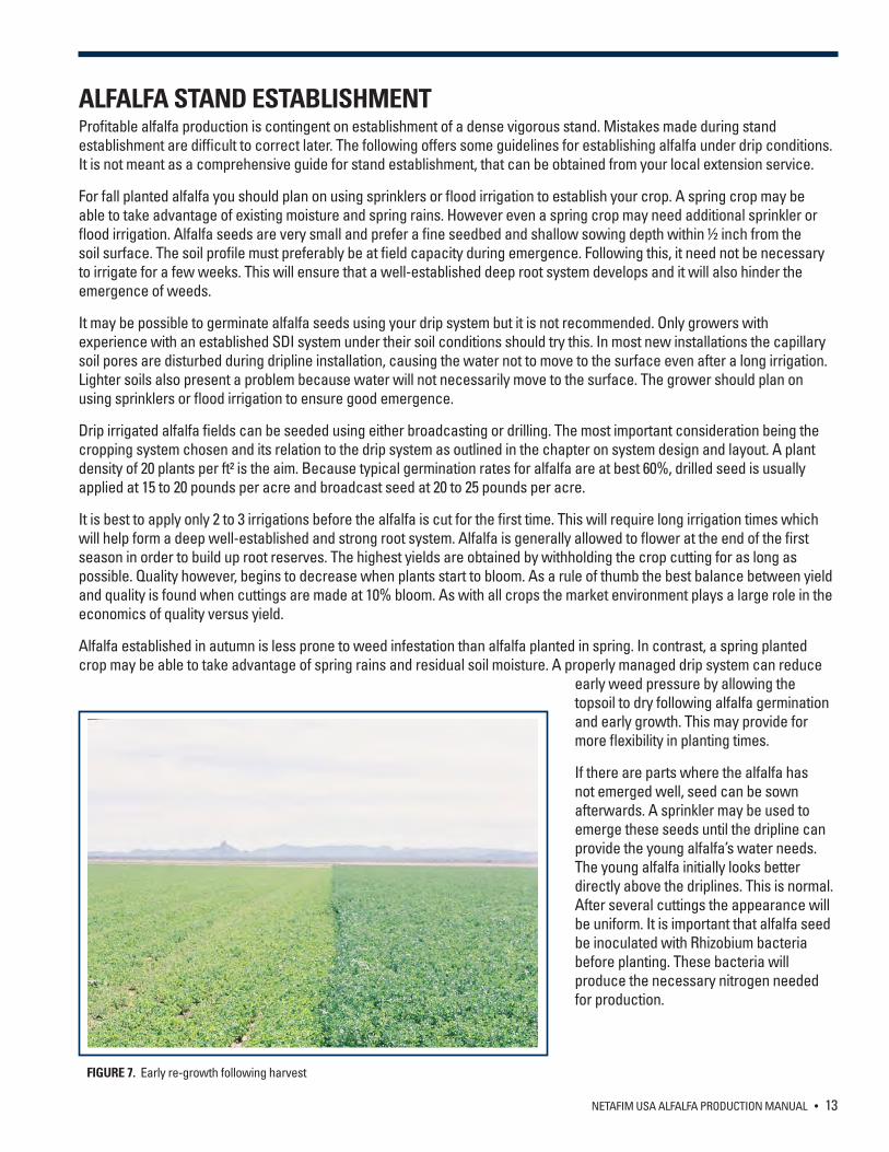
Alfalfa established in autumn is less prone to weed infestation than alfalfa planted in spring. In contrast, a spring planted crop may be able to take advantage of spring rains and residual soil moisture. A properly managed drip system can reduce
early weed pressure by allowing the topsoil to dry following alfalfa germination and early growth. This may provide for more flexibility in planting times.
If there are parts where the alfalfa has not emerged well, seed can be sown afterwards. A sprinkler may be used to emerge these seeds until the dripline can provide the young alfalfa’s water needs. The young alfalfa initially looks better directly above the driplines. This is normal. After several cuttings the appearance will be uniform. It is important that alfalfa seed be inoculated with Rhizobium bacteria before planting. These bacteria will produce the necessary nitrogen needed for production.
FIGURE 7. Early re-growth following harvest
14 • NETAFIM USA ALFALFA PRODUCTION MANUAL
SDI SYSTEM START-UP
OVERVIEW This section offers guidelines for the successful startup and operational testing of your SDI system. Many times your Netafim Dealer will conduct initial start-up and testing of your system. However, during the course of operation there may come times when the system needs to be started after a shutdown such as the off-season or following repairs. These procedures should be followed after any extended shutdown of your system. All drip system owners should make themselves familiar with the process of start-up and testing of their drip system.
SYSTEM STARTUPWhether you have just installed a new system or are starting the system up after sitting through the off season, these simple steps, taken before irrigation will help to ensure optimum system performance.
1. Flush the well before operation through the filter. A new well or one that has been sitting during the off-season, may discharge sand at startup. This ‘plug’ of particles can overwhelm the filtration system causing it to repeatedly trigger an unproductive backflush cycle. If the well discharges sand on a regular basis it may be necessary to install a sand separator before the regular filtration system. Consult your Netafim USA Dealer for more information on sand separators.
2. Thoroughly flush the laterals and mains before system operation. In new systems, during installation, it is possible that dirt and PVC pieces accumulated in the system - these need to be flushed out properly. During the season, systems need to be flushed on a regular basis. Filters do not filter 100% of particles, often fine silt enters. This will settle in lines and must be flushed especially from the driplines. Debris also can get into the lines after a break has occurred and should be flushed after any repairs.
3. Check for leaks in dripline laterals. Laterals are occasionally damaged during installation. System start-up is the right time to check for leaks, before the crop canopy expands making repairs difficult.
STARTUP PROCEDURE The following steps are meant as general guidelines for seasonal or periodic maintenance startup procedures and may not be applicable every time the system is started.
1. Open all the valves to the field as would be done to run an irrigation set. If multiple sets, start with set 1. 2. Based upon water quality, you may need to run the pump on initial startup to a flush pond or ditch. This allows the
water to clear up prior to diverting into the irrigation system. 3. Allow irrigation system to reach design operating pressure and flow rate. 4. Open mainline flush valves and close as many submain valves as required to properly flush the mainline. Consult the
Netafim irrigation dealer for the proper sequence. 5. Flush each drip zone. Consult with the irrigation dealer for proper sequence of flush manifold valve and or number of
laterals to be sequentially flushed. It’s very important to know the proper amount of time to flush the manifold valves and or individual laterals which is why we recommend consulting a Netafim irrigation dealer for timing guidelines. Continue through the entire irrigation system.
6. Return to the pump station and confirm the proper operating pressure and flow are achieved. 7. Check the system for leaks and repair. 8. Re-flush individual lines after leaks are repaired. If laterals are connected to a common flush manifold, do not re-flush
the entire zone. 9. Check for proper operation of all system components; pumps, controllers, valves, air vents, pressure regulators,
gauges, flow meters, filter system and chemical injectors. 10. Record readings from all pressure gauges and flow meters and check on the frequency of backflush cycle of the
filters. The filter backflush frequency can change dramatically with water quality. Consult the Netafim irrigation dealer for proper advice on equipment management.
NETAFIM USA ALFALFA PRODUCTION MANUAL • 15
SYSTEM PRESSURE AND FLOW TESTSUpon initial startup it is best to evaluate the uniformity of your drip system. This is accomplished by:
1. Measuring the pressure in the system at various points and comparing this to the design pressure.2. Reading the water meter or calculating the system flow and comparing the result to the designed flow rate.
These evaluations should be conducted as part of system startup and as an ongoing part of system maintenance. Consult the maintenance section of this manual for a complete program for system care.
SYSTEM PRESSURE EVALUATIONDrip systems are typically designed to operate between 10 and 15 psi. Measuring the pressure at several points in your drip system is the simplest way to evaluate the performance. A good evaluation will include pressure measurements at a minimum of three points along the header end of the field and three points at the far end of the field. Pressure measurements at more points in the field including along the length of the laterals will give a more complete picture of system uniformity but are usually not necessary if the end pressures are within one psi of the header pressure.
SYSTEM FLOW RATEA flow meter is an important component of every drip system. It gives the operator a quick indication of the operational performance of their system and is used to determine proper water application rates. Every new system should be designed with a flow meter. Older systems without flow-meters should be retrofitted with one. The system design should include an estimated system flow rate and the measured flow rate should be within +/- 5% of the designed rate. To calculate the flow rate expected for each zone use the following formula:
Flow rate (GPM) = (0.2) X total length of dripline (ft) in zone X dripper flow rate (GPH) / dripper spacing (in)
CONVERTING SYSTEM FLOW RATE TO INCHES OF APPLIED WATER Irrigation schedules are usually based on evapotranspiration (ET) rates which are expressed in inches of water evaporated over a given time period, usually a day or week. It is simple to convert a flow rate in GPM, either read from a meter or calculate as outlined on previous page, to inches of water applied per hour by using the following formula.
Inches of water applied per hour = (0.00221) X (flow rate, in GPM) / (# acres)
For example, a typical SDI system on alfalfa will have 40 inch spacing between dripline rows with 0.16 GPH drippers spaced at 24 inches. One acre of the above system has 62 rows each, 208 feet long for a total of 12,896 feet. This gives a flow rate of 17.19 GPM.
(.00221) X 17.19/ 1 = 0.038 inches per hour which equals 0.456 inches in 12 hours
MONITORING YOUR DRIP SYSTEM To achieve the highest yields and water savings possible with a drip irrigation system, it is necessary to monitor your system and make adjustments. In addition, regular system monitoring may give advance warning of potential problems.
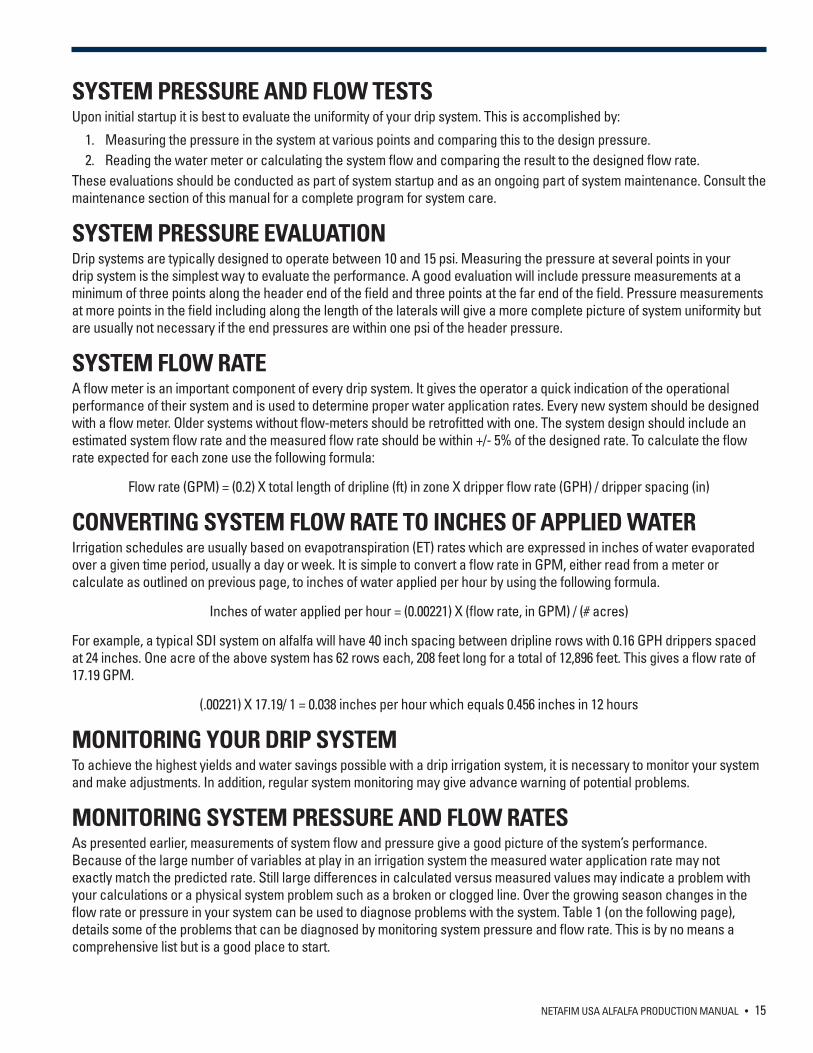
MONITORING SYSTEM PRESSURE AND FLOW RATESAs presented earlier, measurements of system flow and pressure give a good picture of the system’s performance. Because of the large number of variables at play in an irrigation system the measured water application rate may not exactly match the predicted rate. Still large differences in calculated versus measured values may indicate a problem with your calculations or a physical system problem such as a broken or clogged line. Over the growing season changes in the flow rate or pressure in your system can be used to diagnose problems with the system. Table 1 (on the following page), details some of the problems that can be diagnosed by monitoring system pressure and flow rate. This is by no means a comprehensive list but is a good place to start.
16 • NETAFIM USA ALFALFA PRODUCTION MANUAL
INDICATION POSSIBLE PROBLEM
Gradual decrease in flow rate Dripper plugging Possible pump wear (check pressure)
Sudden decrease in flow rate Stuck control valve Water supply failure
Gradual increase in flow rate Incremental damage to dripperline by pests
Sudden increase in flow rate Broken lateral, submain, main line Pressure regulator failure
Large pressure drop across filters Debris buildup in filters Inadequate flushing of filters
Gradual pressure decrease at filter inlet Pump wear or water supply problems
Sudden pressure decrease at filter outlet Broken lateral, submain, main line Pressure regulator or water supply failure
Gradual pressure increase at filter outlet Dripper plugging
Sudden pressure increase at filter outlet Stuck control valve Other flow restrictions
Sudden pressure decrease at submain Damaged or broken lateral
TABLE 1. Problems diagnosed from system flow rates and pressures
NETAFIM USA ALFALFA PRODUCTION MANUAL • 17
IRRIGATION SCHEDULING
INTRODUCTION Subsurface drip irrigation (SDI) will keep the soil closer to the optimum water content, can be applied immediately following cutting and requires less labor than sprinkler or flood irrigation. All of these factors attribute to the higher economic yield possible from using SDI to irrigate alfalfa. Irrigation management has probably the greatest impact on alfalfa yields than any other input. In addition proper irrigation practices will maximize the benefits of other crop inputs such as fertilizer and pest control. No irrigation system gives as much control over water and fertilizer management as SDI.
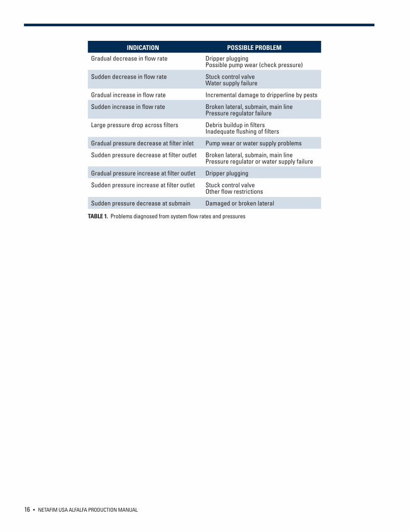
The alfalfa yield response to applied irrigation is similar to most crops. As irrigation increases, so does alfalfa yield, but only to the point where crop needs are met (Figure 8). Applying water over and above crop requirements does not improve yield and only adds to the cost of production. Moreover, excess water may increase pest and disease problems and shorten the life of your alfalfa stand.
The actual shape of the yield response curve varies from location to location and from year to year. The minimum yield without irrigation, the optimum irrigation level and the maximum potential yield vary based on soil type rainfall and seasonal temperatures. For any given set of conditions SDI allows for precise control over root zone moisture and higher yield compared to other irrigation systems.
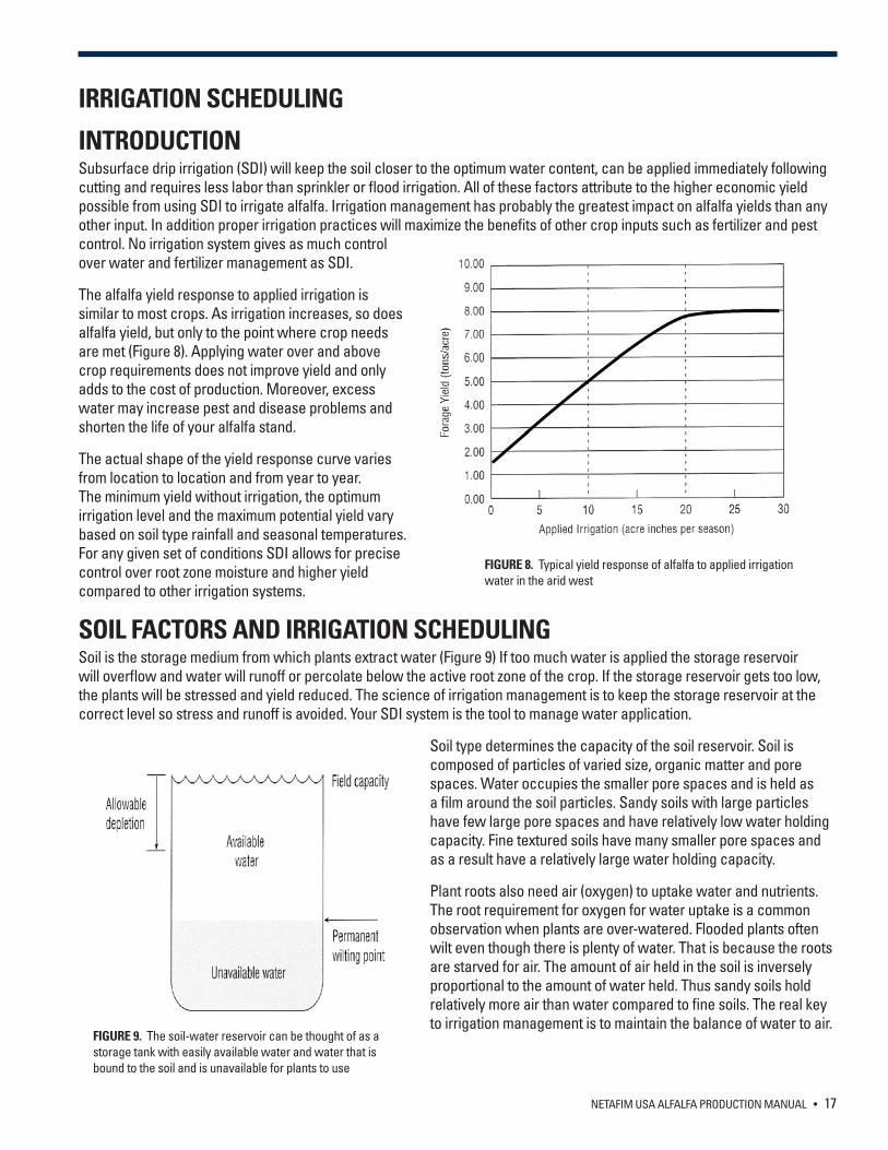
SOIL FACTORS AND IRRIGATION SCHEDULING Soil is the storage medium from which plants extract water (Figure 9) If too much water is applied the storage reservoir will overflow and water will runoff or percolate below the active root zone of the crop. If the storage reservoir gets too low, the plants will be stressed and yield reduced. The science of irrigation management is to keep the storage reservoir at the correct level so stress and runoff is avoided. Your SDI system is the tool to manage water application.
Soil type determines the capacity of the soil reservoir. Soil is composed of particles of varied size, organic matter and pore spaces. Water occupies the smaller pore spaces and is held as a film around the soil particles. Sandy soils with large particles have few large pore spaces and have relatively low water holding capacity. Fine textured soils have many smaller pore spaces and as a result have a relatively large water holding capacity.
Plant roots also need air (oxygen) to uptake water and nutrients. The root requirement for oxygen for water uptake is a common observation when plants are over-watered. Flooded plants often wilt even though there is plenty of water. That is because the roots are starved for air. The amount of air held in the soil is inversely proportional to the amount of water held. Thus sandy soils hold relatively more air than water compared to fine soils. The real key to irrigation management is to maintain the balance of water to air.
FIGURE 8. Typical yield response of alfalfa to applied irrigation water in the arid west
FIGURE 9. The soil-water reservoir can be thought of as a storage tank with easily available water and water that is bound to the soil and is unavailable for plants to use
18 • NETAFIM USA ALFALFA PRODUCTION MANUAL
The water status of the soil can be described in the following manner:
Saturation – The soil is essentially flooded. All pores in the soil contain water. This situation takes place when the rate of water applied exceeds the rate of gravity influenced movement in the soil. This usually occurs immediately after heavy rain or when irrigating using flood and sprinkler systems. The water flow in saturated soil is through the large pores under the influence of gravity.
Field capacity – Gravity has pulled all the water from the largest pores. The smallest pores hold the water against gravity, while the larger pores are filled with air. This is the optimal condition for crop development; the water is held at a force that is easily overcome by the uptake power of the roots, whereas at the same time the soil is sufficiently ventilated to enable the roots to breathe.
Wilting point – Not all the water in the soil is available to the plants. The water held in the film around soil particle or in very small pores is held too tight for the plants to remove it. Plants can be observed to wilt even if the soil feels damp. The wilting point is where the water absorption power of the crop cannot overcome the holding power of the soil. Unlike saturation and field capacity which are primarily influenced by the soil, the wilting point is crop dependent as some crops wilt much more easily than others.
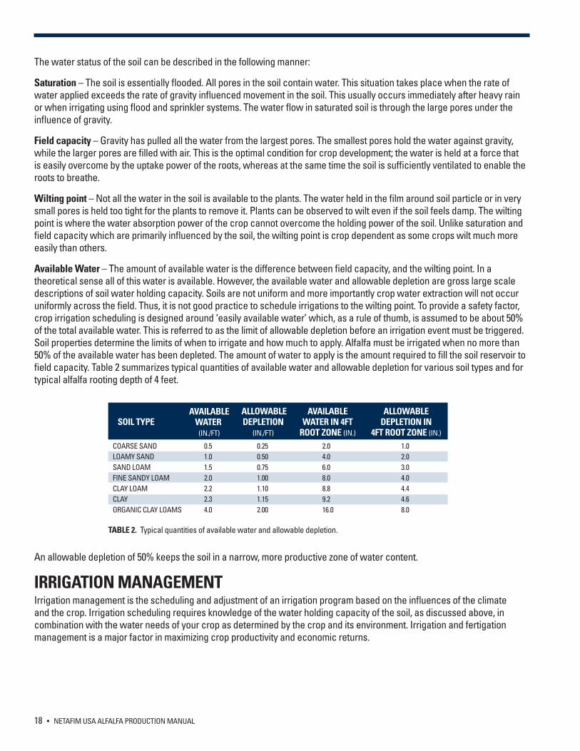
Available Water – The amount of available water is the difference between field capacity, and the wilting point. In a theoretical sense all of this water is available. However, the available water and allowable depletion are gross large scale descriptions of soil water holding capacity. Soils are not uniform and more importantly crop water extraction will not occur uniformly across the field. Thus, it is not good practice to schedule irrigations to the wilting point. To provide a safety factor, crop irrigation scheduling is designed around ‘easily available water’ which, as a rule of thumb, is assumed to be about 50% of the total available water. This is referred to as the limit of allowable depletion before an irrigation event must be triggered. Soil properties determine the limits of when to irrigate and how much to apply. Alfalfa must be irrigated when no more than 50% of the available water has been depleted. The amount of water to apply is the amount required to fill the soil reservoir to field capacity. Table 2 summarizes typical quantities of available water and allowable depletion for various soil types and for typical alfalfa rooting depth of 4 feet.
An allowable depletion of 50% keeps the soil in a narrow, more productive zone of water content.
IRRIGATION MANAGEMENT Irrigation management is the scheduling and adjustment of an irrigation program based on the influences of the climate and the crop. Irrigation scheduling requires knowledge of the water holding capacity of the soil, as discussed above, in combination with the water needs of your crop as determined by the crop and its environment. Irrigation and fertigation management is a major factor in maximizing crop productivity and economic returns.
COARSE SANDLOAMY SANDSAND LOAMFINE SANDY LOAMCLAY LOAMCLAYORGANIC CLAY LOAMS
0.51.01.52.02.22.34.0
0.250.500.751.001.101.152.00
2.04.06.08.08.89.216.0
1.02.03.04.04.44.68.0
SOIL TYPEAVAILABLE
WATER (IN./FT)
ALLOWABLEDEPLETION
(IN./FT)
AVAILABLE WATER IN 4FT
ROOT ZONE (IN.)
ALLOWABLE DEPLETION IN
4FT ROOT ZONE (IN.)
TABLE 2. Typical quantities of available water and allowable depletion.
NETAFIM USA ALFALFA PRODUCTION MANUAL • 19
IRRIGATION SCHEDULING The goal of irrigation scheduling is to determine an irrigation duration and frequency that keeps the root zone below field capacity and above the allowable depletion. At this point the crops roots are exposed to an ample supply of easily available water with sufficient oxygen to promote healthy root growth.
Because drip systems apply water directly to the roots with thousands of water sources throughout the field they are forgiving of poor irrigation scheduling, however, a little time taken to develop and apply an appropriate irrigation schedule will allow your drip system to operate at maximum efficiency.
Two principle methods are used to schedule irrigations in alfalfa fields. One method is called water budgeting and it involves estimating crop water needs based on the evaporative demand of the environment; the other technique relies on soil-based measurements. Both methods have there limitations. The water budgeting method looks at gross water demand and does not specifically look at your crop or soil. Factors are used to adjust for your specific growing conditions. The measurement of soil moisture is limited to the specific areas where measurement devices are placed. If the location of the device is not representative of the entire field the information can be misleading. The best approach is use a combination of both techniques. Most common irrigations are scheduled using water budgeting and verified by measuring soil moisture at select points in the field.
WATER BUDGETING Water budgeting involves tracking additions and losses and balancing them. The losses are due to crop water use, any leach requirements and inefficiencies in the irrigation system. The additions are due to irrigation and rainfall. The objective of the water budget method is to maintain soil moisture near the optimum level by keeping track of crop water use and then irrigating to replace the water used. Knowledge of crop water use is essential to using the water budget approach.
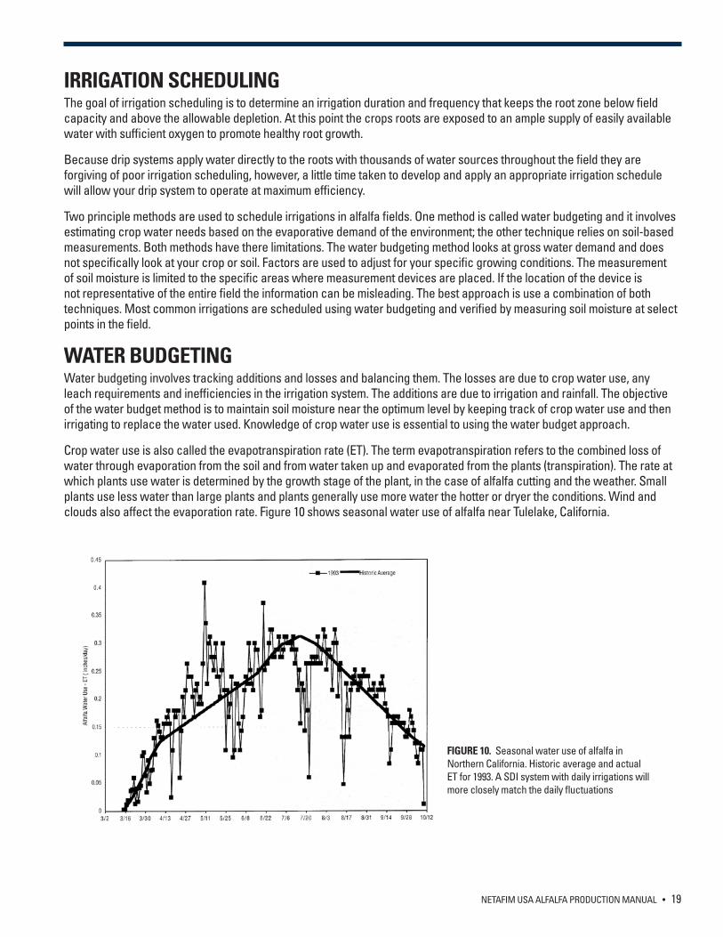
Crop water use is also called the evapotranspiration rate (ET). The term evapotranspiration refers to the combined loss of water through evaporation from the soil and from water taken up and evaporated from the plants (transpiration). The rate at which plants use water is determined by the growth stage of the plant, in the case of alfalfa cutting and the weather. Small plants use less water than large plants and plants generally use more water the hotter or dryer the conditions. Wind and clouds also affect the evaporation rate. Figure 10 shows seasonal water use of alfalfa near Tulelake, California.
FIGURE 10. Seasonal water use of alfalfa in Northern California. Historic average and actual ET for 1993. A SDI system with daily irrigations will more closely match the daily fluctuations
20 • NETAFIM USA ALFALFA PRODUCTION MANUAL
The reference evapotranspiration rate (ETo) can be calculated from weather data or measured as evaporation from a calibrated pan of water. Both methods give a close approximation of the environmentally induced evaporation rate from a given area of soil. Real pan evaporators are still used in many parts of the country and it is simple to construct your own pan evaporator (see the end of this section). However, more frequently the ETo is estimated from weather data which includes, temperature, relative humidity, wind velocity and solar radiation using a modified version of the Pennman equation which relates these variables to evaporation rate. A discussion of the Pennman equation is beyond the scope of this manual. Suffice it to say that the ETo for your area is commonly available from a variety of local sources.
Actual crop water usage is usually not exactly the same as the reference evaporation rate (ETo). First, plants regulate how much water they require by closing or opening stomata (small pores in their leaves used to maintain appropriate water levels in the plant). The difference between the actual peak crop water use and the pan evaporation rate is referred to as the crop factor (Kc). The ET of your crop expressed as ETc can be calculated from the ETo using the following formula. The following is an example of the calculation of the required irrigation time according to reference evaporation:
ETc = ETo x Kc
The crop coefficient (Kc) for alfalfa is 1.15 for a fully leafed out crop. If the ETo either measured from a pan or calculated is 0.4 inches/day then your alfalfa crop will be using:
ETc = 0.4 x 1.15 = 0.46 inches/day (3.22 inches/week) for a fully leafed out crop
Under these conditions, for fine sandy loam or heavier soils, irrigations must be scheduled no less frequently than once a week. Sandier soils will need a minimum of two irrigations per week. Your SDI system can be easily set to provide even daily irrigations with little labor input. More frequent irrigations will keep the soil moisture easily available to your plants and increase the speed of re-growth following cutting. During peak ET periods daily irrigations should be considered.
The water budget system for irrigation is relatively straightforward, but alfalfa cutting and harvesting operations complicate the practical application of this technique. After cutting the alfalfa, the water requirement is reduced. Many publications suggest that the water requirement drops to zero but this is not true as re-growth begins immediately and re-growth requires water. More sophisticated analysis suggests the Kc drops to 0.4 immediately following cutting and rises back to 1.15 after 10 days. Experience has shown that irrigating with your SDI system immediately following harvest results in more rapid re-growth compared to flood or sprinkler irrigations which must wait 5 to 7 days following cutting to be applied.
Relative to sprinkler and flood irrigation scheduling of your irrigation using SDI is much simpler. There is no need to interrupt irrigations due to harvest and curing. Soil wetness is a small issue and under most conditions equipment can enter the fields even during irrigation. Operating labor is much more efficient allowing for more focus on crop management as setting up and managing the system. In short an SDI system allows you to focus on maximizing yield and not managing the system.
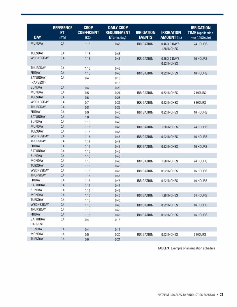
PRACTICAL EXAMPLE OF IRRIGATION SCHEDULING An example should help clarify the preceding discussion on watering frequency and quantity. This example is based on a hypothetical alfalfa crop on a 28 day harvest cycle. This is only an example and must be adjusted for your local conditions. Using an ETo of 0.4 inches per day and a crop coefficient of 1.15 for a fully developed crop and 0.4 for a crop that has just been cut we can construct a 30 day irrigation program. The program is based on 3 irrigations a week on Monday, Wednesday and Friday.
The first step is to calculate the number of irrigation hours to return the water that was consumed by the crop. A common hourly application rate for an SDI system is 0.056 inches/hour. Using this application rate the required irrigation time would be as follows:
Irrigation time = daily water needs / hourly rate = (0.46/0.057) 8 hrs for a mature crop
We then construct an irrigation table. For simplicity we will use the same reference ET (ETo) for every day we adjust the crop coefficient for harvest.
NETAFIM USA ALFALFA PRODUCTION MANUAL • 21
MONDAY
TUESDAYWEDNESDAY
THURSDAYFRIDAYSATURDAY(HARVEST)SUNDAYMONDAYTUESDAYWEDNESDAYTHURSDAYFRIDAYSATURDAYSUNDAYMONDAYTUESDAYWEDNESDAYTHURSDAYFRIDAYSATURDAYSUNDAYMONDAYTUESDAYWEDNESDAYTHURSDAYFRIDAYSATURDAYSUNDAYMONDAYTUESDAYWEDNESDAYTHURSDAYFRIDAYSATURDAYHARVESTSUNDAYMONDAYTUESDAY
0.4
0.40.4
0.40.40.4
0.40.40.40.40.40.40.40.40.40.40.40.40.40.40.40.40.40.40.40.40.40.40.40.40.40.40.40.4
0.40.40.4
1.15
1.151.15
1.151.150.4
0.40.50.60.70.80.91.01.151.151.151.151.151.151.151.151.151.151.151.151.151.151.151.151.151.151.151.150.4
0.40.50.6
0.46
0.460.46
0.460.460.160.160.200.240.280.320.360.400.460.460.460.460.460.460.460.460.460.460.460.460.460.460.460.460.460.460.460.460.460.16
0.160.200.24
IRRIGATION
IRRIGATION
IRRIGATION
IRRIGATION
IRRIGATION
IRRIGATION
IRRIGATION
IRRIGATION
IRRIGATION
IRRIGATION
IRRIGATION
IRRIGATION
IRRIGATION
IRRIGATION
IRRIGATION
IRRIGATION
DAY
REFERENCEET
(ETo)
CROPCOEFFICIENT
(KC)
DAILY CROPREQUIREMENT
ETc (in./day) IRRIGATION
EVENTS0.46 X 3 DAYS1.38 INCHES
0.46 X 2 DAYS0.92 INCHES
0.92 INCHES
0.52 INCHES
0.52 INCHES
0.92 INCHES
1.38 INCHES
0.92 INCHES
0.92 INCHES
1.38 INCHES
0.92 INCHES
0.92 INCHES
1.38 INCHES
0.92 INCHES
0.92 INCHES
0.52 INCHES
IRRIGATIONAMOUNT (in.)
24 HOURS
16 HOURS
16 HOURS
7 HOURS
8 HOURS
16 HOURS
24 HOURS
16 HOURS
16 HOURS
24 HOURS
16 HOURS
16 HOURS
24 HOURS
16 HOURS
16 HOURS
7 HOURS
IRRIGATIONTIME (Application
rate 0.057in./hr)
TABLE 3. Example of an irrigation schedule
22 • NETAFIM USA ALFALFA PRODUCTION MANUAL
In practice a simple spreadsheet can be employed to calculate the ETc and the irrigation required to fill up the soil reservoir. In the above example it takes 8 hours to apply the daily ETc. The plant water needs would be satisfied with an eight hour irrigation each day. In practice 3 fields could be irrigated with this water supply with each field being irrigated for 8 hours per day. When irrigating multiple fields it is a good idea to schedule irrigations so that the same field is not irrigated at the same time each day. In the above example each of the three fields could be irrigated for 2 hours so that all three fields are irrigated during the day or at night. While it would be possible to set irrigation at a lower frequency, experience has shown that more frequent irrigations give better results.
INFLUENCE OF RAINFALL ON IRRIGATION In many regions there is rainfall during the irrigation season. It is necessary to consider the quantity of water provided by the rainfall based on the soil condition and crop. The agronomical term ‘Effective Rainfall’ refers to that part of rainfall that is considered as available water.
If the rainfall provides less than ¼ inch and is the first rain, there is no need to consider this amount as a water contribution to the soil. Stronger rainfall providing ½ inch or more must be taken in account according to the specific circumstances.
It is difficult to predict which part of rainfall is the effective rain. However, in the case of strong rainfall providing up to 2 inches, the effective rain may be no more than 60% of the total quantity. If a rainfall provides 2 inches or more, only 1½ inch will be considered as effective rain and the rest will be runoff.
It is obvious that these calculations require a certain amount of interpretation. Hence, it is highly recommended to check the status of the water in the soil in the active root zone using the hands, soil drill or tensiometers before resuming irrigation. The use of tensiometer may provide valuable information, since the readings will indicate the presence of water in the root zone.
MONITORING SOIL MOISTURE Measuring the soil moisture content is a good way to check and make adjustments to your irrigation schedule. In areas that receive significant rainfall soil moisture measurements are critical in assessing the amount of useful water received in a rain event.
There are several practical ways to assess soil moisture content. Experience irrigation specialists can use the ‘look and feel’ method where the moisture level is determined by handling a soil sample. This is an excellent way to confirm the measurements given by more sophisticated equipment
Tensiometers measure the tension which the soil is holding onto the water (soil metric potential). Tension is a measure of the work a plant must do to remove water from the soil. The higher the tension the harder the plant must work to remove water from the soil. Tension is usually expressed in bar or centibar (1 bar = 100 centibar). The drier the soil, the more tightly the soil holds onto the water and the higher the tension measurement. The main drawback to tensiometers is that they require a certain skill to set-up and operate properly.
There a numerous sensors that measure the moisture content of the soil. The most common are gypsum blocks but new sensors such as capacitance and resistance sensors are being developed all the time. Moisture content is a measurement of the water contained in the soil as a percentage of the volume of the entire soil solution. In general, sensors do not measure the moisture content directly but use an electronic calculation to infer the water content of the soil. Measurements expressed as moisture content can directly indicate how much water you need to apply to bring the soil to field capacity. The main drawback to these sensors it that they are sensitive to salts in the soil and water. Newer models do a good job of correcting for salt concentration but they may need to be calibrated more often than you think.
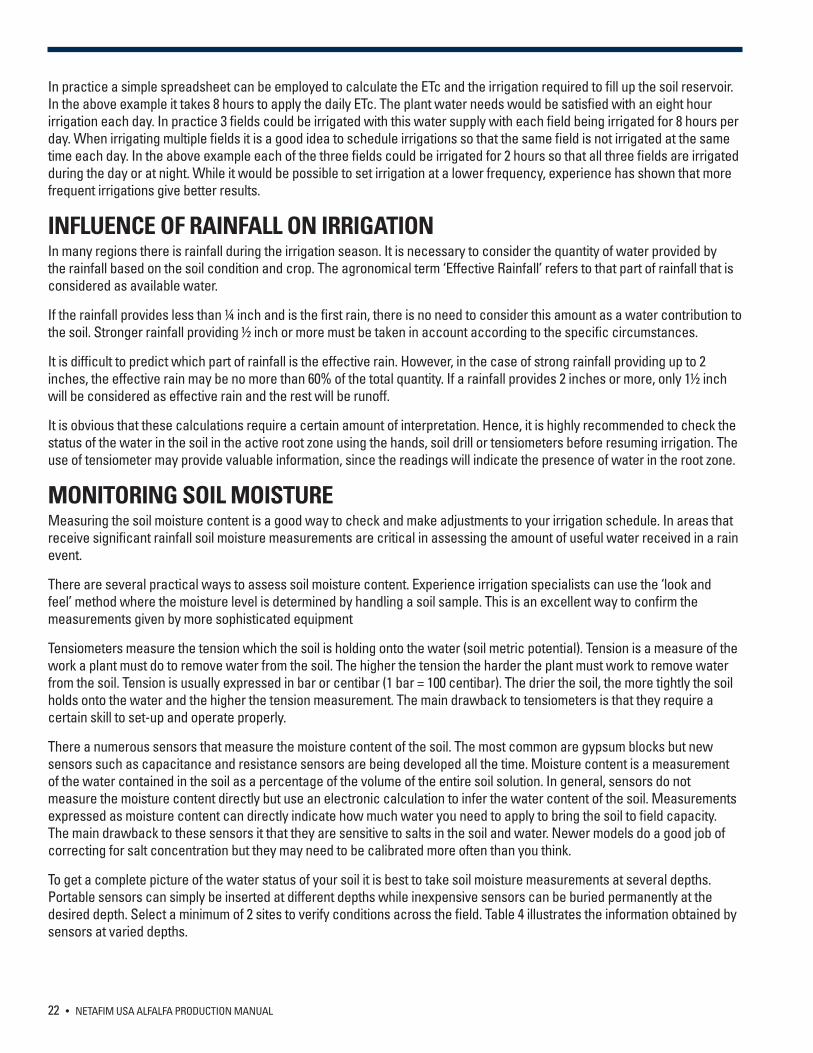
To get a complete picture of the water status of your soil it is best to take soil moisture measurements at several depths. Portable sensors can simply be inserted at different depths while inexpensive sensors can be buried permanently at the desired depth. Select a minimum of 2 sites to verify conditions across the field. Table 4 illustrates the information obtained by sensors at varied depths.
NETAFIM USA ALFALFA PRODUCTION MANUAL • 23
MONITORING SOIL SALINITY Even with low salinity water, salt can accumulate in the soil unless some leaching occurs. In addition to the salts that are in the soil and are a part of almost all irrigation water, fertilizers can add to the salt content. It is best practice to send irrigation water and soil samples to a lab for analysis. In problem areas consider purchasing an EC sensor which will give instantaneous read outs of water and soil salt conditions. If salt levels are found to be increasing over time it is necessary to include a leach factor to your irrigation system.
IRRIGATION SCHEDULING – EFFECT OF CROP GROWTH STAGE BEFORE SOWING A common practice is to fill the soil profile with water prior to sowing seed. There are advantages to wetting a deep soil profile before sowing:
• The crop is developed at the first stage without irrigation. • All crop cultivation, such as weed treatment and shallow ripping, take place between germination and first irrigation,
which is an optimal situation since the topsoil is not wet. • The soil wetness enables the development of deep roots, which support the crop. • Deep soil wetness serves like a water conservation tank. In emergency situations, such as pumping and dam problems
or power cuts, the crop could use this water until the problem is solved with minimal damage. The calculation for the amount of water required to fill the soil profile is the same as that for the calculation of total available water given earlier.
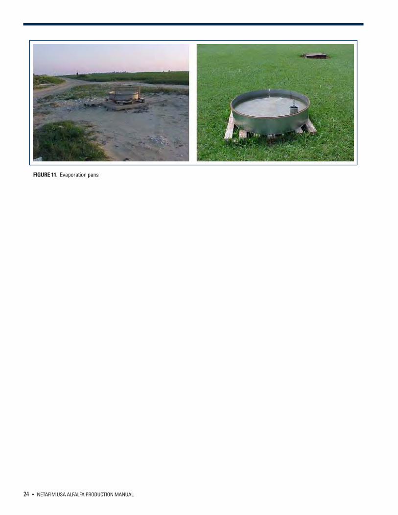
CONSTRUCTING YOUR OWN PAN EVAPORATOR It is possible to construct your own pan evaporator. The pan is round-shaped with a diameter of 48 inches and a depth of 10 inches. It is fabricated from galvanized steel and coated with aluminum paint and installed on a wooden platform. A pallet works great. The pan base must be at least 2 inches above the ground. The pan is filled with water to about 2 inches under the brim. The pan must be placed in an open space. There should not be any tall objects such as buildings or trees that could cast a shadow on the pan or obstruct the wind at a radius of 175 feet. There should not be weeds around the pan at a radius of 75 feet. Level reading must be performed daily at the same time, usually in the early morning. The reading will display the evaporation value of the previous day. If a reading is not taken during the weekend, it is possible to take the reading after the weekend and to calculate the average for each day. It is a good idea to keep permanent records because these readings could serve as a valuable tool for planning the water quantities required for irrigation in different seasons.
NOTE: Deficit irrigation, an irrigation schedule that deliberately keeps soil moisture below field capacity, can be used to conserve water during times of interrupted supply. Recent research has shown that deficit irrigation used at correct times during the growing season can result in significant water savings with little effect on yield. Because entire sections of the field are irrigated uniformly, drip irrigation is better suited than all other irrigation systems for precise deficit irrigation.
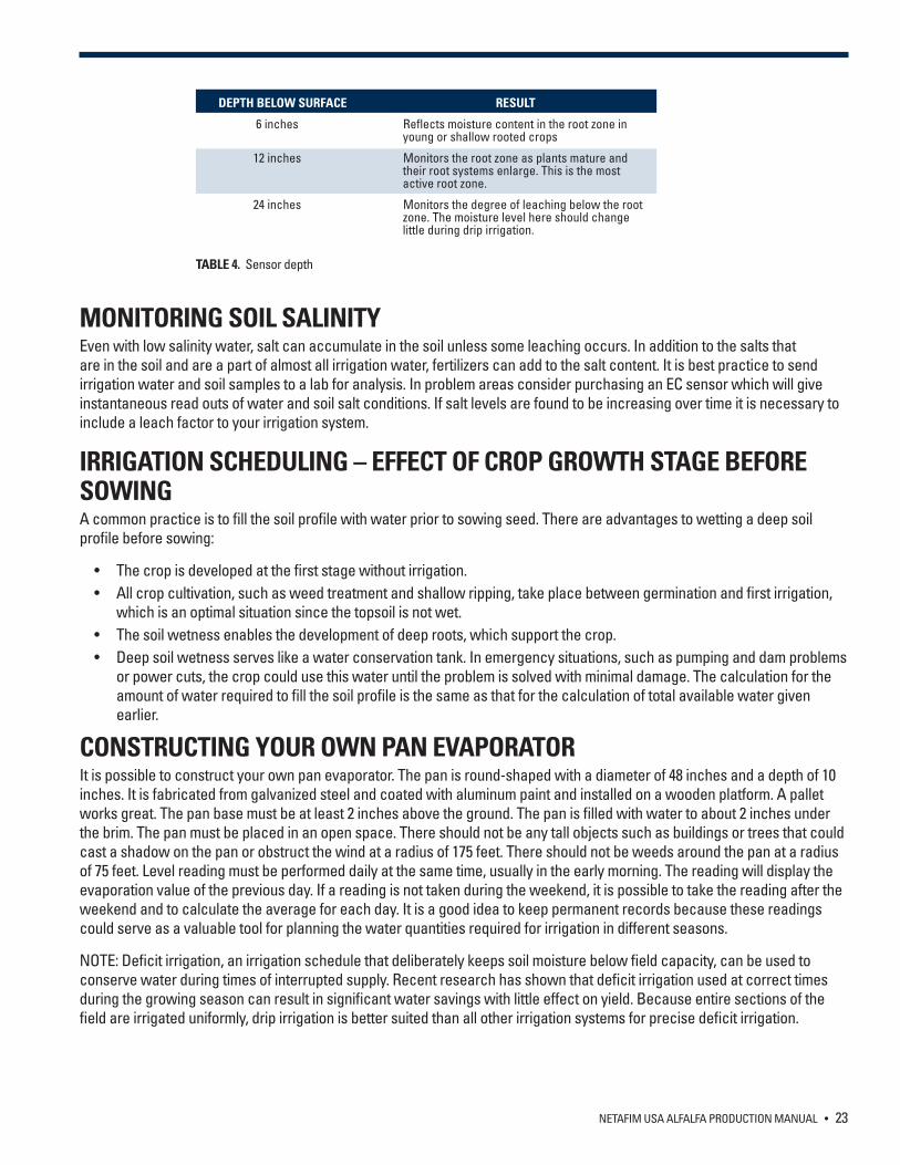
DEPTH BELOW SURFACE RESULT
6 inches Reflects moisture content in the root zone in young or shallow rooted crops
12 inches Monitors the root zone as plants mature and their root systems enlarge. This is the most active root zone.
24 inches Monitors the degree of leaching below the root zone. The moisture level here should change little during drip irrigation.
TABLE 4. Sensor depth
24 • NETAFIM USA ALFALFA PRODUCTION MANUAL
FIGURE 11. Evaporation pans
NETAFIM USA ALFALFA PRODUCTION MANUAL • 25
FERTILIZATION OF ALFALFA Subsurface drip irrigation applies fertilizer directly to the root zone (Nutrigation). This is the most efficient method to deliver fertilizer to a permanent crop such as alfalfa. The ability to use the SDI system for delivering fertilizer means that the interval between fertilizer applications can be reduced without a large labor input. As a result it is possible to maintain a near optimum level of nutrients in the soil helping boost the vigor and longevity of your alfalfa crop. In addition, applying fertilizer directly to the root zone results in less waste which may reduce the fertilizer required per pound of yield.
ESSENTIAL PLANT NUTRIENTS Fourteen mineral elements are needed in varying amounts for plant growth. In the case of alfalfa, thirteen are supplied by the soil and one, nitrogen, from bacteria in root nodules. To fix nitrogen these bacterium also require cobalt, which is not needed by green plants. Growth slows or stops when one of these nutrients are in short supply. Thus all nutrients must be available in adequate amounts during the growing season.
Evaluating the nutrient status of your crop and soil is a key aspect of designing a fertilizer program for your alfalfa crop. This evaluation can be done by visual observation, soil analysis and plant tissue testing. Using all three provides the best results. Nutrient deficiencies may exhibit visual plant symptoms such as obvious stunting or yellowing. Consult you local extension for visual guides for each of the nutrient deficiencies. Unfortunately visual symptoms can often be confused with insect injury, diseases and restricted root growth. In addition, once a deficiency results in a visual symptom there has already been a yield reduction. Therefore it is good to be familiar with deficiency symptoms in the odd case they are manifested during growth but more emphasis should be place on soil and tissue samples.
Soils tests provide an estimate of nutrient availability for uptake by plants. Soil tests must be taken prior to planting and the soil amended based on the laboratories recommendations for alfalfa. Some growers rely solely on soil testing to determine their fertilizer regime during the life of the crop, however, it is more common to use tissue tests for this purpose. The objective of soil testing is to get a fertility map of the field. Samples should be taken from areas that are troublesome as well as productive regions often referred to as benchmark areas. The benchmark areas should be chosen so that they can be located year after year.
Taking soil samples from a drip irrigated field is slightly different than sprinkler or flood irrigated fields. The drip system creates a wetted area in the soil profile. Nutrients injected through the drip system are only found in this wetted area. It is important to sample within this wetted area to get a good assessment of the fertility of the soil. The goal is to test near the dripline but not to hit it. This can be tricky. It is a good idea to develop some type of marker system so you can find an appropriate spot.
Plant tissue testing is by far the most precise method of determining the nutrient needs of alfalfa. Such tests are the best reflection of what nutrients the plant has taken up and are far more accurate than soil tests, particularly for sulphur, boron and molybdenum. Plant tissue tests give rapid feedback on the current fertility status of the plants and the effectiveness of fertilization.
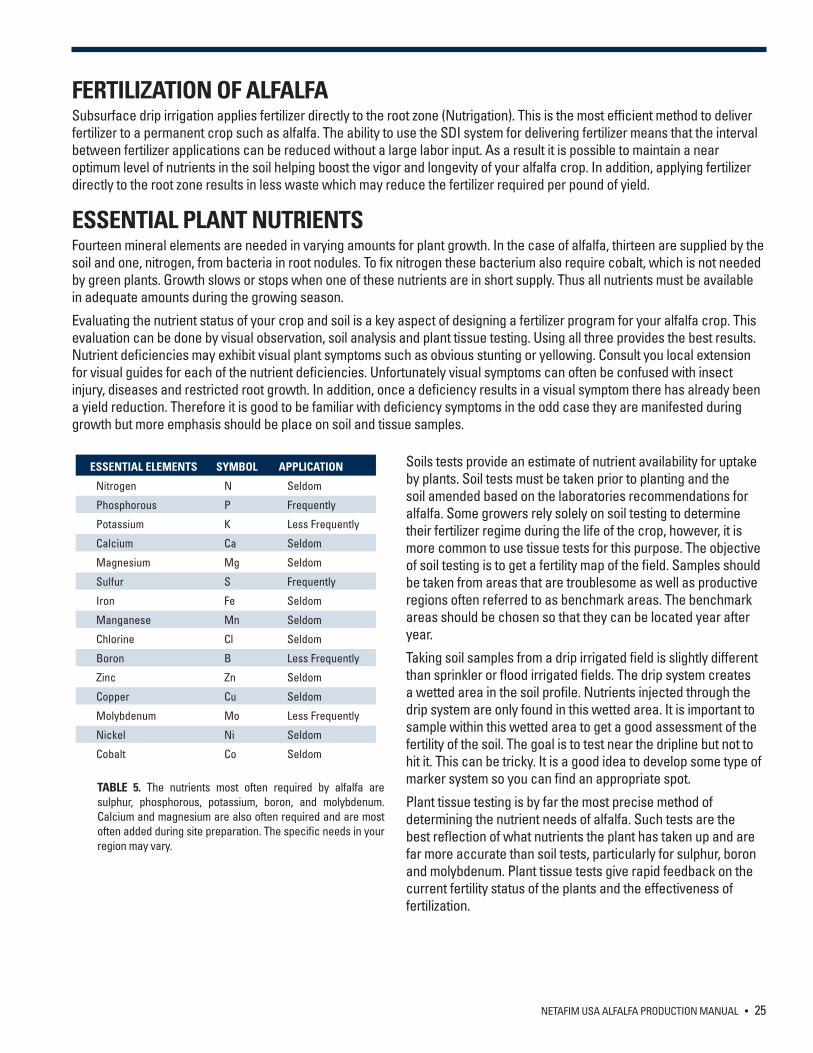
ESSENTIAL ELEMENTS SYMBOL APPLICATION
Nitrogen N Seldom
Phosphorous P Frequently
Potassium K Less Frequently
Calcium Ca Seldom
Magnesium Mg Seldom
Sulfur S Frequently
Iron Fe Seldom
Manganese Mn Seldom
Chlorine Cl Seldom
Boron B Less Frequently
Zinc Zn Seldom
Copper Cu Seldom
Molybdenum Mo Less Frequently
Nickel Ni Seldom
Cobalt Co Seldom
TABLE 5. The nutrients most often required by alfalfa are sulphur, phosphorous, potassium, boron, and molybdenum. Calcium and magnesium are also often required and are most often added during site preparation. The specific needs in your region may vary.
26 • NETAFIM USA ALFALFA PRODUCTION MANUAL
The best time to take tissue tests is when the plant is in the 1/10th bloom stage. When alfalfa is cut prior to the 1/10th bloom (bud stage) tissue nutrient concentrations should be about 10% higher than when sampled at the 1/10th bloom. Samples are best collected at first cutting to catch deficiencies, particularly sulfur, early. Collect 40 to 60 stems from at least 30 plants in each benchmark area.
Different parts of the plant are analyzed for different nutrients. Follow the instructions of your local laboratory. In general, the top third of the plant (stems and leaves) are analyzed for Boron, Molybdenum and Copper. The middle one-third of the stem is used to assess Phosphorous and Potassium and the middle one-third of the leaves are used to assess Sulfur. The lower one-third of the stem is not used.
Tissue tests can determine only the single most limiting nutrient, the tissue concentration of other nutrients even if in short supply may appear to be normal because of reduced growth. Therefore after a deficiency is corrected another tissue sample should be taken and analyzed to see if other elements are limiting growth. Also low nutrient concentrations in plant tissue may not mean a deficiency in the soil. A problem affecting plant roots such as nematodes will reduce nutrient uptake. This is a good reason to use a combination of tissue and soil analyses.
CORRECTING NUTRIENT DEFICIENCIES The strategy for correcting nutrient deficiencies in fields with SDI are to first incorporate appropriate levels of fertilizer according to soil tests to achieve adequate levels in the soil. Second, during the growth of the crop the SDI system is used to supply nutrients as necessary to maintain vigor and maximize yield. Depending upon soil type, fertigation should be done a minimum of one to three months.
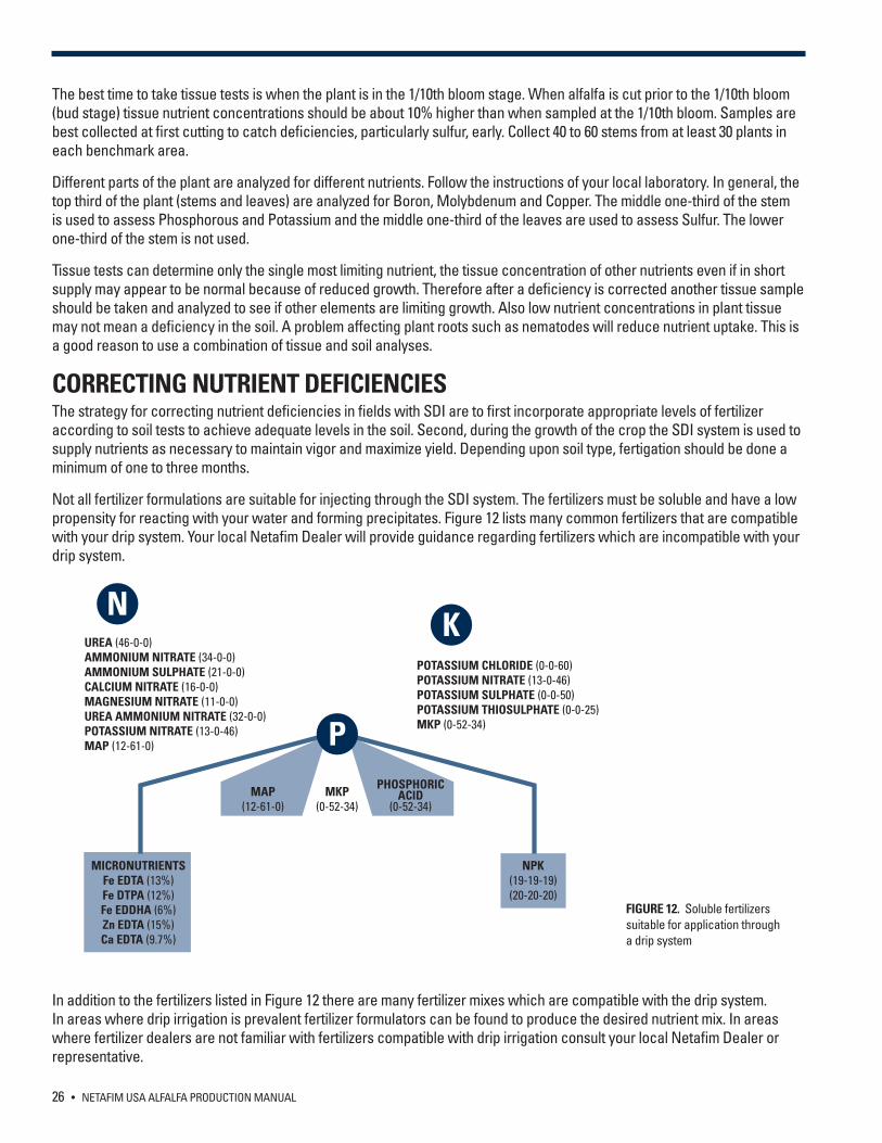
Not all fertilizer formulations are suitable for injecting through the SDI system. The fertilizers must be soluble and have a low propensity for reacting with your water and forming precipitates. Figure 12 lists many common fertilizers that are compatible with your drip system. Your local Netafim Dealer will provide guidance regarding fertilizers which are incompatible with your drip system.
In addition to the fertilizers listed in Figure 12 there are many fertilizer mixes which are compatible with the drip system. In areas where drip irrigation is prevalent fertilizer formulators can be found to produce the desired nutrient mix. In areas where fertilizer dealers are not familiar with fertilizers compatible with drip irrigation consult your local Netafim Dealer or representative.
FIGURE 12. Soluble fertilizers suitable for application through a drip system
P
MAP(12-61-0)
MICRONUTRIENTSFe EDTA (13%)Fe DTPA (12%)Fe EDDHA (6%)Zn EDTA (15%)Ca EDTA (9.7%)
MKP(0-52-34)
PHOSPHORICACID
(0-52-34)
NPK(19-19-19)(20-20-20)
KPOTASSIUM CHLORIDE (0-0-60)POTASSIUM NITRATE (13-0-46)POTASSIUM SULPHATE (0-0-50)POTASSIUM THIOSULPHATE (0-0-25)MKP (0-52-34)
NUREA (46-0-0)AMMONIUM NITRATE (34-0-0)AMMONIUM SULPHATE (21-0-0)CALCIUM NITRATE (16-0-0)MAGNESIUM NITRATE (11-0-0)UREA AMMONIUM NITRATE (32-0-0)POTASSIUM NITRATE (13-0-46)MAP (12-61-0)
NETAFIM USA ALFALFA PRODUCTION MANUAL • 27
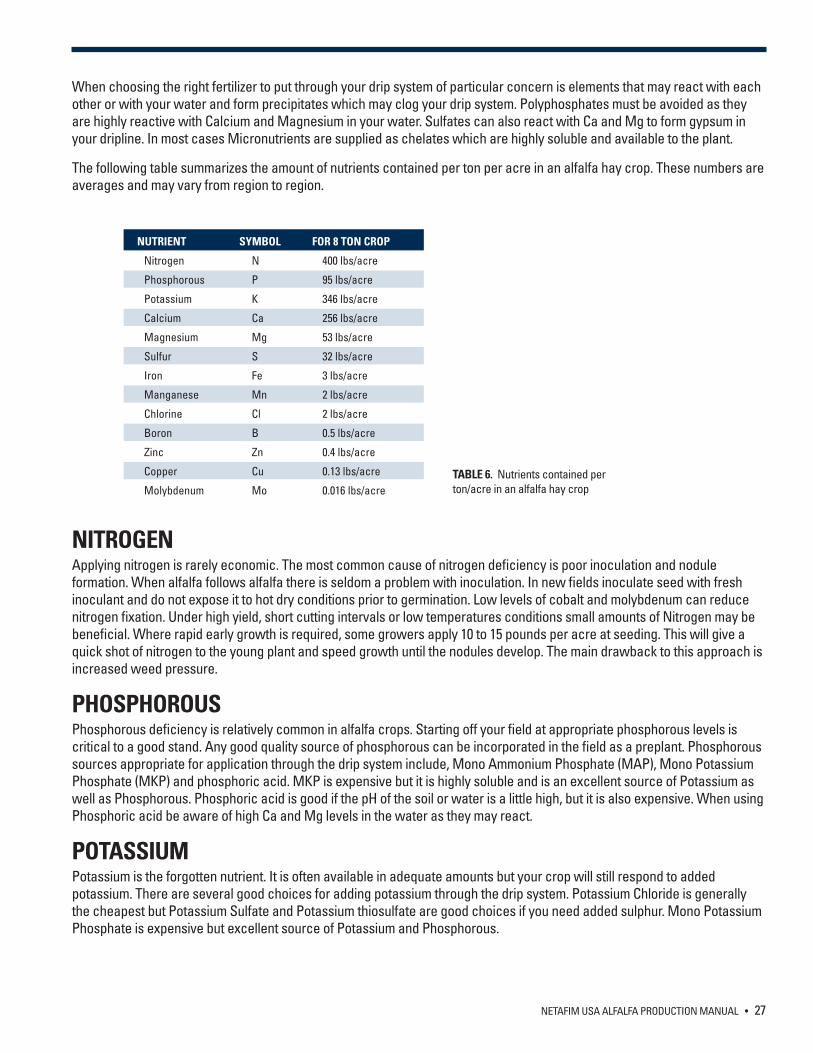
When choosing the right fertilizer to put through your drip system of particular concern is elements that may react with each other or with your water and form precipitates which may clog your drip system. Polyphosphates must be avoided as they are highly reactive with Calcium and Magnesium in your water. Sulfates can also react with Ca and Mg to form gypsum in your dripline. In most cases Micronutrients are supplied as chelates which are highly soluble and available to the plant.
The following table summarizes the amount of nutrients contained per ton per acre in an alfalfa hay crop. These numbers are averages and may vary from region to region.
NITROGEN Applying nitrogen is rarely economic. The most common cause of nitrogen deficiency is poor inoculation and nodule formation. When alfalfa follows alfalfa there is seldom a problem with inoculation. In new fields inoculate seed with fresh inoculant and do not expose it to hot dry conditions prior to germination. Low levels of cobalt and molybdenum can reduce nitrogen fixation. Under high yield, short cutting intervals or low temperatures conditions small amounts of Nitrogen may be beneficial. Where rapid early growth is required, some growers apply 10 to 15 pounds per acre at seeding. This will give a quick shot of nitrogen to the young plant and speed growth until the nodules develop. The main drawback to this approach is increased weed pressure.
PHOSPHOROUS Phosphorous deficiency is relatively common in alfalfa crops. Starting off your field at appropriate phosphorous levels is critical to a good stand. Any good quality source of phosphorous can be incorporated in the field as a preplant. Phosphorous sources appropriate for application through the drip system include, Mono Ammonium Phosphate (MAP), Mono Potassium Phosphate (MKP) and phosphoric acid. MKP is expensive but it is highly soluble and is an excellent source of Potassium as well as Phosphorous. Phosphoric acid is good if the pH of the soil or water is a little high, but it is also expensive. When using Phosphoric acid be aware of high Ca and Mg levels in the water as they may react.
POTASSIUM Potassium is the forgotten nutrient. It is often available in adequate amounts but your crop will still respond to added potassium. There are several good choices for adding potassium through the drip system. Potassium Chloride is generally the cheapest but Potassium Sulfate and Potassium thiosulfate are good choices if you need added sulphur. Mono Potassium Phosphate is expensive but excellent source of Potassium and Phosphorous.
NUTRIENT SYMBOL FOR 8 TON CROP
Nitrogen N 400 lbs/acre
Phosphorous P 95 lbs/acre
Potassium K 346 lbs/acre
Calcium Ca 256 lbs/acre
Magnesium Mg 53 lbs/acre
Sulfur S 32 lbs/acre
Iron Fe 3 lbs/acre
Manganese Mn 2 lbs/acre
Chlorine Cl 2 lbs/acre
Boron B 0.5 lbs/acre
Zinc Zn 0.4 lbs/acre
Copper Cu 0.13 lbs/acre
Molybdenum Mo 0.016 lbs/acreTABLE 6. Nutrients contained per ton/acre in an alfalfa hay crop

28 • NETAFIM USA ALFALFA PRODUCTION MANUAL
SULFUR It is important to have an adequate level of sulfur in the soil prior to planting. However, soil tests are not a reliable method for predicting sulfur deficiency in a growing crop. The best approach is to determine if there is a history of sulfur efficiency in your area. If Sulfur is needed, the most economical practice is to apply and incorporate elemental sulfur at 200 to 300 pounds per acre. At this rate elemental sulfur can last 4 to 7 years. The elemental sulfur will be gradually converted to the phytoactive sulphate form. To ensure a long slow release the particle size of the sulfur should range from 10 percent 100 mesh to 60 percent 6 mesh. The finer 100 mesh particles will convert to sulphate faster than the larger particles.
After the crop is established, tissue testing must be used to confirm a sulfur deficiency. In this case sulfur can be applied through the drip system. Potassium sulphate and potassium thiosulphate are expensive but rapid acting sulfur sources which also supply potassium. Fine gypsum can be applied through the drip system but this must be done in a controlled manner or it can clog the drip system. Consult you Netafim Dealer before applying gypsum through your system. Ammonium sulphate can be used as well as sulfuric acid. These are not common choices as the former supplies unneeded nitrogen and the latter is dangerous to handle.
IRON Iron deficiency must be confirmed with a tissue test. Chelated Iron is the best choice for application through the drip system.
BORON AND MOLYBDENUM Alfalfa is a Boron-tolerant crop. If your rotation includes Boron sensitive crops such as cereals then boron should be supplied in low doses through the drip system. Molybdenum deficiency is not common. Tissue tests should be used to confirm either Boron or Molybdenum deficiency. Boron and Molybdenum are both available in soluble form which can be applied through the drip system as a foliar spray. It is common to apply a micronutrient combination on a regular basis to the alfalfa crop.
CALCIUM AND MAGNESIUM Calcium and Magnesium deficiencies are not common in alfalfa. The levels of these nutrients in the soil should be adjusted prior to planting. Alkaline water or soil can contain a lot of calcium and magnesium in comparison to potassium, which makes it important to apply maintenance potassium even if the soil analyses show adequate potassium levels. Gypsum and magnesium sulphate are good sources for these nutrients.
NETAFIM USA ALFALFA PRODUCTION MANUAL • 29
FERTIGATION Fertigation is the application of liquid or dissolved water-soluble fertilizer through the irrigation system in a controlled and efficient manner. The best way to maximize the performance of alfalfa is to install a fertigation unit that will accurately inject fertilizers into the water supply for uptake by the crop.
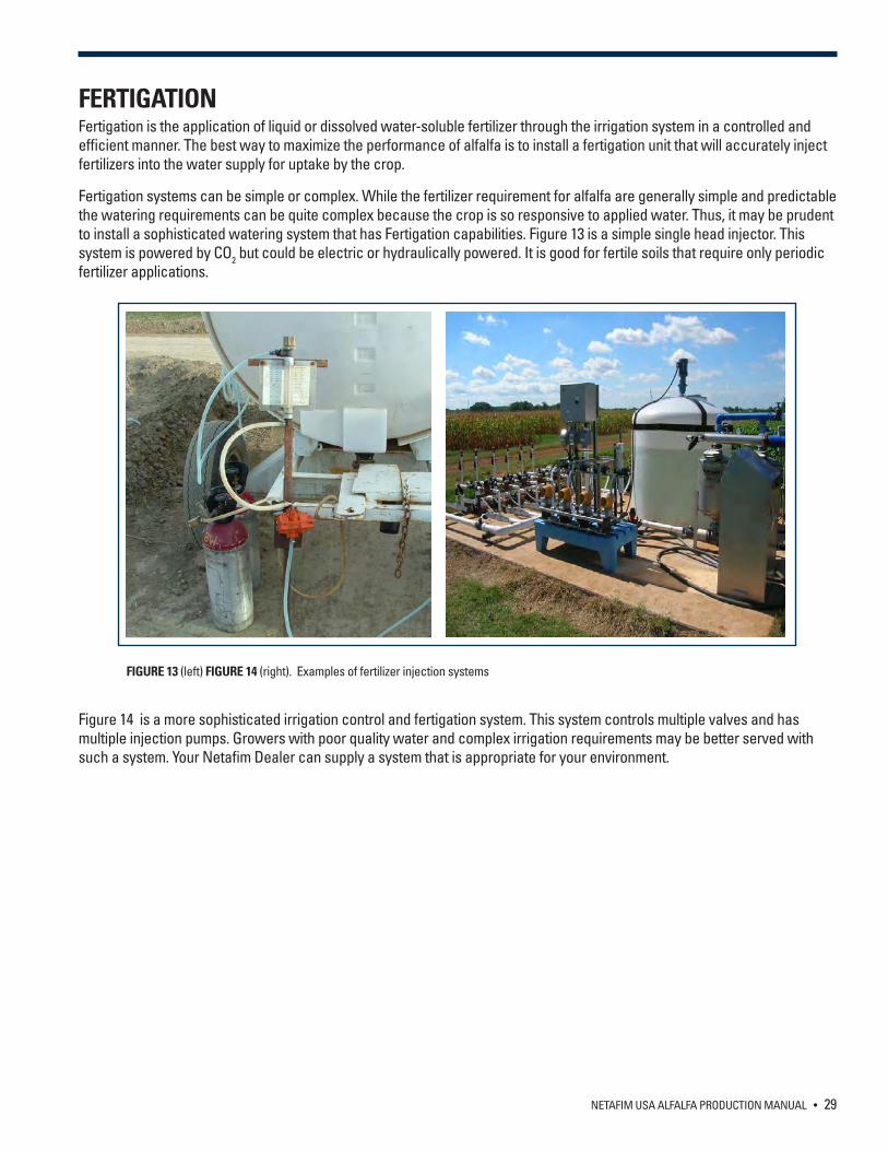
Fertigation systems can be simple or complex. While the fertilizer requirement for alfalfa are generally simple and predictable the watering requirements can be quite complex because the crop is so responsive to applied water. Thus, it may be prudent to install a sophisticated watering system that has Fertigation capabilities. Figure 13 is a simple single head injector. This system is powered by CO2 but could be electric or hydraulically powered. It is good for fertile soils that require only periodic fertilizer applications.
Figure 14 is a more sophisticated irrigation control and fertigation system. This system controls multiple valves and has multiple injection pumps. Growers with poor quality water and complex irrigation requirements may be better served with such a system. Your Netafim Dealer can supply a system that is appropriate for your environment.
FIGURE 13 (left) FIGURE 14 (right). Examples of fertilizer injection systems
30 • NETAFIM USA ALFALFA PRODUCTION MANUAL
DRIP SYSTEM MAINTENANCEThe maintenance of your SDI system centers on identification of the factors which can lead to reduction of the performance of your drip system and procedures to mitigate these negative impacts. Factors that can slow or stop flow through the drip system include: suspended material, chemical precipitation, biological growth, root intrusion, soil ingestion and crimping of the dripline. To ensure maximum system life reduce or eliminate the impact of the negative factors (Table 1, page 18). This may require water treatment and a systematic program for regular maintenance. In this section we outline the various potential issues that can adversely affect the drip system and offer procedures to mitigate the potential damage.
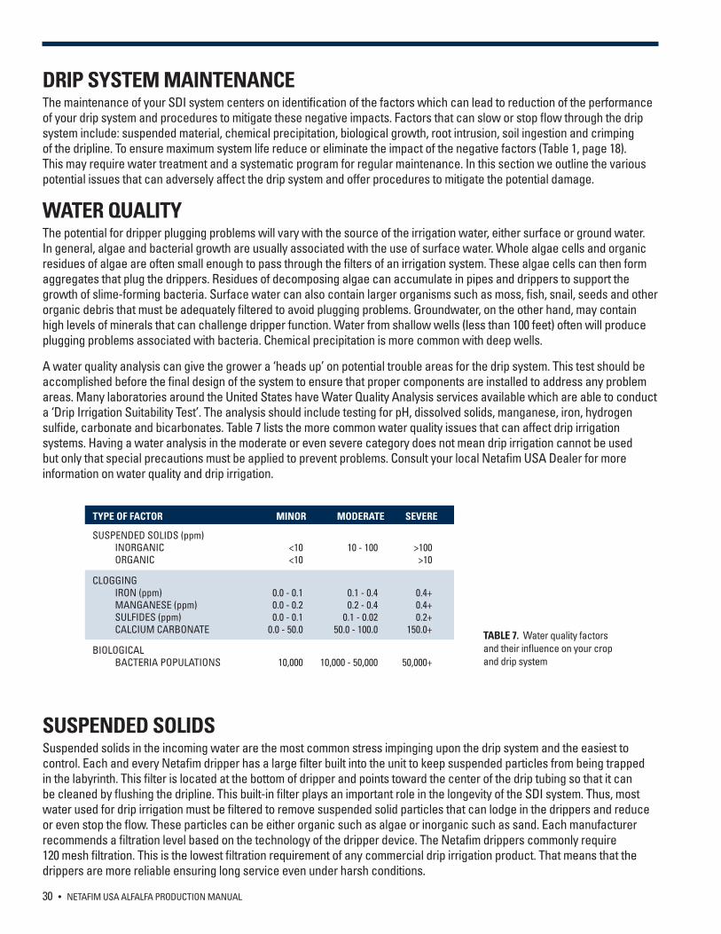
WATER QUALITYThe potential for dripper plugging problems will vary with the source of the irrigation water, either surface or ground water. In general, algae and bacterial growth are usually associated with the use of surface water. Whole algae cells and organic residues of algae are often small enough to pass through the filters of an irrigation system. These algae cells can then form aggregates that plug the drippers. Residues of decomposing algae can accumulate in pipes and drippers to support the growth of slime-forming bacteria. Surface water can also contain larger organisms such as moss, fish, snail, seeds and other organic debris that must be adequately filtered to avoid plugging problems. Groundwater, on the other hand, may contain high levels of minerals that can challenge dripper function. Water from shallow wells (less than 100 feet) often will produce plugging problems associated with bacteria. Chemical precipitation is more common with deep wells.
A water quality analysis can give the grower a ‘heads up’ on potential trouble areas for the drip system. This test should be accomplished before the final design of the system to ensure that proper components are installed to address any problem areas. Many laboratories around the United States have Water Quality Analysis services available which are able to conduct a ‘Drip Irrigation Suitability Test’. The analysis should include testing for pH, dissolved solids, manganese, iron, hydrogen sulfide, carbonate and bicarbonates. Table 7 lists the more common water quality issues that can affect drip irrigation systems. Having a water analysis in the moderate or even severe category does not mean drip irrigation cannot be used but only that special precautions must be applied to prevent problems. Consult your local Netafim USA Dealer for more information on water quality and drip irrigation.
SUSPENDED SOLIDS Suspended solids in the incoming water are the most common stress impinging upon the drip system and the easiest to control. Each and every Netafim dripper has a large filter built into the unit to keep suspended particles from being trapped in the labyrinth. This filter is located at the bottom of dripper and points toward the center of the drip tubing so that it can be cleaned by flushing the dripline. This built-in filter plays an important role in the longevity of the SDI system. Thus, most water used for drip irrigation must be filtered to remove suspended solid particles that can lodge in the drippers and reduce or even stop the flow. These particles can be either organic such as algae or inorganic such as sand. Each manufacturer recommends a filtration level based on the technology of the dripper device. The Netafim drippers commonly require 120 mesh filtration. This is the lowest filtration requirement of any commercial drip irrigation product. That means that the drippers are more reliable ensuring long service even under harsh conditions.
TYPE OF FACTOR MINOR MODERATE SEVERE
SUSPENDED SOLIDS (ppm) INORGANIC <10 10 - 100 >100 ORGANIC <10 >10
CLOGGING IRON (ppm) 0.0 - 0.1 0.1 - 0.4 0.4+ MANGANESE (ppm) 0.0 - 0.2 0.2 - 0.4 0.4+ SULFIDES (ppm) 0.0 - 0.1 0.1 - 0.02 0.2+ CALCIUM CARBONATE 0.0 - 50.0 50.0 - 100.0 150.0+
BIOLOGICAL BACTERIA POPULATIONS 10,000 10,000 - 50,000 50,000+
TABLE 7. Water quality factors and their influence on your crop and drip system
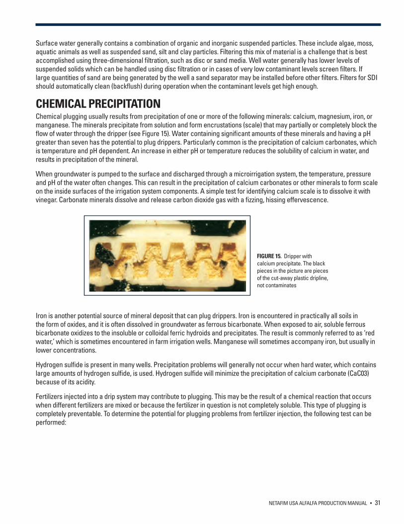
NETAFIM USA ALFALFA PRODUCTION MANUAL • 31
Surface water generally contains a combination of organic and inorganic suspended particles. These include algae, moss, aquatic animals as well as suspended sand, silt and clay particles. Filtering this mix of material is a challenge that is best accomplished using three-dimensional filtration, such as disc or sand media. Well water generally has lower levels of suspended solids which can be handled using disc filtration or in cases of very low contaminant levels screen filters. If large quantities of sand are being generated by the well a sand separator may be installed before other filters. Filters for SDI should automatically clean (backflush) during operation when the contaminant levels get high enough.
CHEMICAL PRECIPITATIONChemical plugging usually results from precipitation of one or more of the following minerals: calcium, magnesium, iron, or manganese. The minerals precipitate from solution and form encrustations (scale) that may partially or completely block the flow of water through the dripper (see Figure 15). Water containing significant amounts of these minerals and having a pH greater than seven has the potential to plug drippers. Particularly common is the precipitation of calcium carbonates, which is temperature and pH dependent. An increase in either pH or temperature reduces the solubility of calcium in water, and results in precipitation of the mineral.
When groundwater is pumped to the surface and discharged through a microirrigation system, the temperature, pressure and pH of the water often changes. This can result in the precipitation of calcium carbonates or other minerals to form scale on the inside surfaces of the irrigation system components. A simple test for identifying calcium scale is to dissolve it with vinegar. Carbonate minerals dissolve and release carbon dioxide gas with a fizzing, hissing effervescence.
Iron is another potential source of mineral deposit that can plug drippers. Iron is encountered in practically all soils in the form of oxides, and it is often dissolved in groundwater as ferrous bicarbonate. When exposed to air, soluble ferrous bicarbonate oxidizes to the insoluble or colloidal ferric hydroids and precipitates. The result is commonly referred to as ‘red water,’ which is sometimes encountered in farm irrigation wells. Manganese will sometimes accompany iron, but usually in lower concentrations.
Hydrogen sulfide is present in many wells. Precipitation problems will generally not occur when hard water, which contains large amounts of hydrogen sulfide, is used. Hydrogen sulfide will minimize the precipitation of calcium carbonate (CaC03) because of its acidity.
Fertilizers injected into a drip system may contribute to plugging. This may be the result of a chemical reaction that occurs when different fertilizers are mixed or because the fertilizer in question is not completely soluble. This type of plugging is completely preventable. To determine the potential for plugging problems from fertilizer injection, the following test can be performed:
FIGURE 15. Dripper with calcium precipitate. The black pieces in the picture are pieces of the cut-away plastic dripline, not contaminates
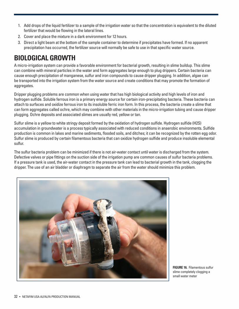
32 • NETAFIM USA ALFALFA PRODUCTION MANUAL
1. Add drops of the liquid fertilizer to a sample of the irrigation water so that the concentration is equivalent to the diluted fertilizer that would be flowing in the lateral lines.
2. Cover and place the mixture in a dark environment for 12 hours. 3. Direct a light beam at the bottom of the sample container to determine if precipitates have formed. If no apparent
precipitation has occurred, the fertilizer source will normally be safe to use in that specific water source.
BIOLOGICAL GROWTHA micro-irrigation system can provide a favorable environment for bacterial growth, resulting in slime buildup. This slime can combine with mineral particles in the water and form aggregates large enough to plug drippers. Certain bacteria can cause enough precipitation of manganese, sulfur and iron compounds to cause dripper plugging. In addition, algae can be transported into the irrigation system from the water source and create conditions that may promote the formation of aggregates.
Dripper plugging problems are common when using water that has high biological activity and high levels of iron and hydrogen sulfide. Soluble ferrous iron is a primary energy source for certain iron-precipitating bacteria. These bacteria can attach to surfaces and oxidize ferrous iron to its insoluble ferric iron form. In this process, the bacteria create a slime that can form aggregates called ochre, which may combine with other materials in the micro-irrigation tubing and cause dripper plugging. Ochre deposits and associated slimes are usually red, yellow or tan.
Sulfur slime is a yellow to white stringy deposit formed by the oxidation of hydrogen sulfide. Hydrogen sulfide (H2S) accumulation in groundwater is a process typically associated with reduced conditions in anaerobic environments. Sulfide production is common in lakes and marine sediments, flooded soils, and ditches; it can be recognized by the rotten egg odor. Sulfur slime is produced by certain filamentous bacteria that can oxidize hydrogen sulfide and produce insoluble elemental sulfur.
The sulfur bacteria problem can be minimized if there is not air-water contact until water is discharged from the system. Defective valves or pipe fittings on the suction side of the irrigation pump are common causes of sulfur bacteria problems. If a pressure tank is used, the air-water contact in the pressure tank can lead to bacterial growth in the tank, clogging the dripper. The use of an air bladder or diaphragm to separate the air from the water should minimize this problem.
FIGURE 16. Filamentous sulfur slime completely clogging a small water meter
NETAFIM USA ALFALFA PRODUCTION MANUAL • 33
ROOT INTRUSIONPlant roots tend to grow toward soil areas with the highest water content. Because of this tendency, roots can clog SDI systems by growing into the dripper openings. Plant roots tend to ‘hunt’ for water when it is in short supply thus, the problem seems to be more acute when irrigation is not sufficient for the plant needs. This is a particular problem in systems that are left unused for part of the season. Several strategies can be employed to reduce the possibility of root intrusion:
1. Short frequent irrigations keep adequate water in the root zone so the roots have no need to look for water.2. Acid injection that lowers the pH to less than four will discourage root growth and can be used to clean roots out of
drippers with small amounts of root intrusion. High concentrations of chlorine (100 to 400 ppm), N-pHURIC, phosphoric or metam sodium (Vapam) will also destroy roots in the drippers.
3. In areas where it is allowed, trifluralin is an effective inhibitor of root growth and can be used to prevent root intrusion.4. Seamed dripline encourages roots to grow along the seam and into the dripper. Netafim Products are designed
without a seam to discourage this intrusion.
SOIL INGESTIONSoil ingestion is not a problem in properly designed SDI systems. Soil injection occurs when soil is sucked into the drip tube. When a drip system is shut off the water continues to flow to the low end of the field creating a vacuum at the higher end, sucking saturated soil into the line. A properly designed drip system will minimize this potential problem. The supply manifold must be equipped with vacuum relief valves, these valves allow air to flow into the driplines when the system is shut off. Netafim air/vacuum relief valves will allow sufficient air into the system. Insufficient air will create a vacuum (similar to not using valves). This is not a good place to skimp.
CRIMPING OF THE DRIPLINECrimping of the dripline can occur as the result of soil disturbance by equipment or drying out. Because it is difficult to correct crimping in an SDI system many alfalfa growers are setting up their system so there is minimum traffic on the driplines. The lines are installed using GPS and the field is laid with specific traffic rows.
MAINTENANCE PROCEDURESFILTER MAINTENANCE Follow the standard instructions for the maintenance of your filter system. Filters are the first line of protection for your drip system and they need regular maintenance to operate at a high level. On a biweekly basis observe the system as it completes a backflush cycle. Make sure all pressures are within the system limits before and after backflushing. Check the operation of backflush valves, pressure differential switches and controller. Make sure you clean the command filter. At the end of the season check the media level in media tanks. Scum can build up on disc filters and the discs may need to be cleaned with acid. In areas that experience a freeze drain all water from the filter, valves and command system.
DRIPLINE FLUSHINGTo minimize sediment build up, regular flushing of drip irrigation pipelines is recommended. The system design should be such that a minimum flush rate of 1.5 ft/sec can be obtained in the lines. Valves large enough to allow sufficient velocity of flow should be installed at the ends of mains, submains and manifolds. Also, allowances for flushing should be made at the ends of lateral lines. Flushing of the drip lateral lines should continue until clean water runs from the flushed line for at least two minutes. A regular maintenance program of inspection and flushing will help significantly in preventing dripper plugging. At shutdown it is best to flush all fertilizer from the lateral lines prior to shutting the irrigation system down.
CHEMICAL TREATMENTChemical treatment is often required to prevent dripper plugging due to microbial growth and/or mineral precipitation. The attachment of inorganic particles to microbial slime is a significant source of dripper plugging. Chlorination is an effective measure against microbial activity. Use chlorine and all other chemicals only according to label directions. Acid injection can remove scale deposits, reduce or eliminate mineral precipitation and create an environment unsuitable for microbial growth.
34 • NETAFIM USA ALFALFA PRODUCTION MANUAL
CHLORINE INJECTIONOVERVIEWChlorination is the most common method for treating organic contaminants. Active chlorine is a strong oxidizer and is useful in achieving the following:
A. Prevent clogging and sedimentation of organic substances.B. Destroy and decompose sulfur and iron bacteria, as well as accumulated bacterial slime in the system.C. Improve performance of filtration systems while reducing backflush water.D. Clean systems of organic sediments. (Chlorine has no effect on scale deposits.)
If the micro-irrigation system water source is not chlorinated, it is a good practice to equip the system to inject chlorine to suppress microbial growth. Since bacteria can grow within filters, chlorine injection should occur prior to filtration.
Liquid sodium hypochlorite (NaOCl)--laundry bleach--is available at several chlorine concentrations. The higher concentrations are often more economical. It is the easiest form of chlorine to handle and is most often used in drip irrigation systems. Powdered calcium hypochlorite (CaCOCl2), also called High Test Hypochlorite (HTH), is not recommended for injection into micro-irrigation systems since it can produce precipitates that can plug drippers, especially at high pH levels. The following are several possible chlorine injection schemes:
• Inject continuously at a low level to obtain one to two ppm of free chlorine at the ends of the laterals. • Inject at intervals (once at the end of each irrigation cycle) at concentrations of 20 ppm and for a duration long enough
to reach the last dripper in the system. • Inject a slug treatment in high concentrations (50 ppm) weekly at the end of an irrigation cycle and for a duration
sufficient to distribute the chlorine through the entire piping system. The method used will depend on the growth potential of microbial organisms, the injection method and equipment and the scheduling of injection of other chemicals.
When chlorine is injected, a test kit should be used to check to see that the injection rate is sufficient. Color test kits (D.P.D.) that measure ‘free residual’ chlorine, which is the primary bactericidal agent, should be used. The orthotolidine-type test kit, which is often used to measure total chlorine content in swimming pools, is not satisfactory for this purpose. D.P.D. test kits can be purchased from irrigation equipment dealers. Check the water at the outlet farthest from the injection pump. There should be a residual chlorine concentration of one to two ppm at that point. Irrigation system flow rates should be closely monitored, and action taken (chlorination) if flow rates decline.
Chlorination for bacterial control is relatively ineffective above pH 7.5, so acid additions may be necessary to lower the pH to increase the biocidal action of chlorine for more alkaline waters. Since sodium hypochlorite can react with emulsifiers, fertilizers, herbicides and insecticides, bulk chemicals should be stored in a secure place according to label directions.
RECIPE FOR CHLORINE INJECTION WARNING: Active chlorine solutions are dangerous to human beings and animals - the manufacturers’ instructions must be followed very carefully. When using chlorine, proper protection for the eyes, hands and body parts must be worn, i.e. glasses, gloves, shoes, etc. Chlorine contact with the skin can cause serious burns, contact with the eyes can cause blindness and swallowing may be fatal. Prior to filling any tank with chlorine solution, be sure it is absolutely clean of fertilizer residue. Direct contact between chlorine and fertilizer can create a thermo reaction, which can be explosive. This is extremely dangerous. The direct contact of chlorine and fertilizer in the irrigation water after it has been injected into the system is not hazardous.
The contact of free chlorine in water and nitrogenous (ammonium and urea) fertilizer creates the combination of chloramine which is called ‘combined chlorine’. If possible, avoid any application of ammonium or urea fertilizers together with chlorination.
In the case that chlorination is required, it is recommended to ask your local Farm Extension Service for assistance in the computation and application methods.
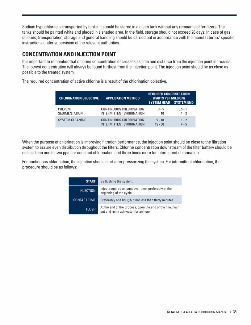
NETAFIM USA ALFALFA PRODUCTION MANUAL • 35
Sodium hypochlorite is transported by tanks. It should be stored in a clean tank without any remnants of fertilizers. The tanks should be painted white and placed in a shaded area. In the field, storage should not exceed 20 days. In case of gas chlorine, transportation, storage and general handling should be carried out in accordance with the manufacturers’ specific instructions under supervision of the relevant authorities.
CONCENTRATION AND INJECTION POINTIt is important to remember that chlorine concentration decreases as time and distance from the injection point increases. The lowest concentration will always be found furthest from the injection point. The injection point should be as close as possible to the treated system.
The required concentration of active chlorine is a result of the chlorination objective.
When the purpose of chlorination is improving filtration performance, the injection point should be close to the filtration system to assure even distribution throughout the filters. Chlorine concentration downstream of the filter battery should be no less than one to two ppm for constant chlorination and three times more for intermittent chlorination.
For continuous chlorination, the injection should start after pressurizing the system. For intermittent chlorination, the procedure should be as follows:
REQUIRED CONCENTRATION CHLORINATION OBJECTIVE APPLICATION METHOD (PARTS PER MILLION) SYSTEM HEAD SYSTEM END
PREVENT CONTINUOUS CHLORINATION 3 - 5 0.5 - 1SEDIMENTATION INTERMITTENT CHORINATION 10 1 - 2
SYSTEM CLEANING CONTINUOUS CHLORINATION 5 - 10 1 - 2 INTERMITTENT CHORINATION 15 - 50 4 - 5
START By flushing the system.
INJECTION Inject required amount over time, preferably at the beginning of the cycle.
CONTACT TIME Preferably one hour, but not less than thirty minutes.
FLUSH At the end of the process, open the end of the line, flush out and run fresh water for an hour.
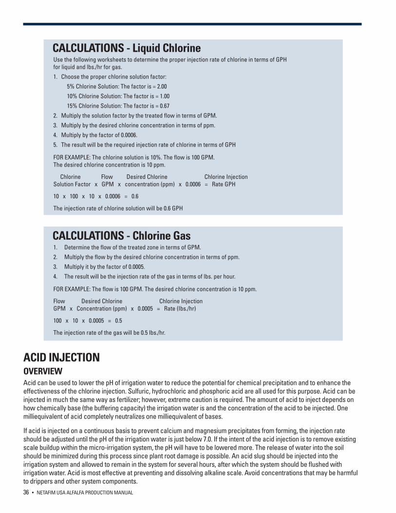
36 • NETAFIM USA ALFALFA PRODUCTION MANUAL
CALCULATIONS - Liquid ChlorineUse the following worksheets to determine the proper injection rate of chlorine in terms of GPH for liquid and lbs./hr for gas.
1. Choose the proper chlorine solution factor:
5% Chlorine Solution: The factor is = 2.00
10% Chlorine Solution: The factor is = 1.00
15% Chlorine Solution: The factor is = 0.67
2. Multiply the solution factor by the treated flow in terms of GPM.
3. Multiply by the desired chlorine concentration in terms of ppm.
4. Multiply by the factor of 0.0006.
5. The result will be the required injection rate of chlorine in terms of GPH
FOR EXAMPLE: The chlorine solution is 10%. The flow is 100 GPM. The desired chlorine concentration is 10 ppm.
Chlorine Flow Desired Chlorine Chlorine InjectionSolution Factor x GPM x concentration (ppm) x 0.0006 = Rate GPH
10 x 100 x 10 x 0.0006 = 0.6
The injection rate of chlorine solution will be 0.6 GPH
CALCULATIONS - Chlorine Gas1. Determine the flow of the treated zone in terms of GPM.
2. Multiply the flow by the desired chlorine concentration in terms of ppm.
3. Multiply it by the factor of 0.0005.
4. The result will be the injection rate of the gas in terms of lbs. per hour.
FOR EXAMPLE: The flow is 100 GPM. The desired chlorine concentration is 10 ppm.
Flow Desired Chlorine Chlorine InjectionGPM x Concentration (ppm) x 0.0005 = Rate (Ibs./hr)
100 x 10 x 0.0005 = 0.5
The injection rate of the gas will be 0.5 lbs./hr.
ACID INJECTIONOVERVIEWAcid can be used to lower the pH of irrigation water to reduce the potential for chemical precipitation and to enhance the effectiveness of the chlorine injection. Sulfuric, hydrochloric and phosphoric acid are all used for this purpose. Acid can be injected in much the same way as fertilizer; however, extreme caution is required. The amount of acid to inject depends on how chemically base (the buffering capacity) the irrigation water is and the concentration of the acid to be injected. One milliequivalent of acid completely neutralizes one milliequivalent of bases.
If acid is injected on a continuous basis to prevent calcium and magnesium precipitates from forming, the injection rate should be adjusted until the pH of the irrigation water is just below 7.0. If the intent of the acid injection is to remove existing scale buildup within the micro-irrigation system, the pH will have to be lowered more. The release of water into the soil should be minimized during this process since plant root damage is possible. An acid slug should be injected into the irrigation system and allowed to remain in the system for several hours, after which the system should be flushed with irrigation water. Acid is most effective at preventing and dissolving alkaline scale. Avoid concentrations that may be harmful to drippers and other system components.
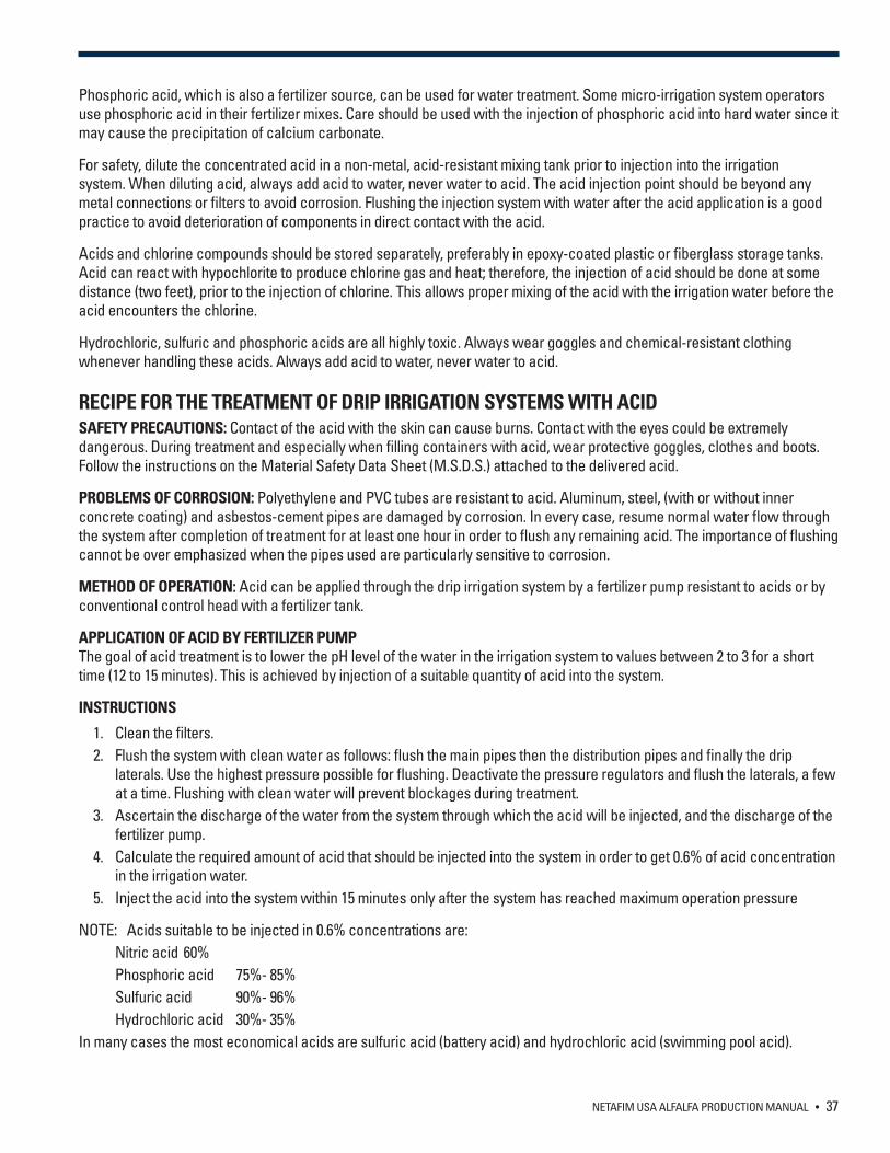
NETAFIM USA ALFALFA PRODUCTION MANUAL • 37
Phosphoric acid, which is also a fertilizer source, can be used for water treatment. Some micro-irrigation system operators use phosphoric acid in their fertilizer mixes. Care should be used with the injection of phosphoric acid into hard water since it may cause the precipitation of calcium carbonate.
For safety, dilute the concentrated acid in a non-metal, acid-resistant mixing tank prior to injection into the irrigation system. When diluting acid, always add acid to water, never water to acid. The acid injection point should be beyond any metal connections or filters to avoid corrosion. Flushing the injection system with water after the acid application is a good practice to avoid deterioration of components in direct contact with the acid.
Acids and chlorine compounds should be stored separately, preferably in epoxy-coated plastic or fiberglass storage tanks. Acid can react with hypochlorite to produce chlorine gas and heat; therefore, the injection of acid should be done at some distance (two feet), prior to the injection of chlorine. This allows proper mixing of the acid with the irrigation water before the acid encounters the chlorine.
Hydrochloric, sulfuric and phosphoric acids are all highly toxic. Always wear goggles and chemical-resistant clothing whenever handling these acids. Always add acid to water, never water to acid.
RECIPE FOR THE TREATMENT OF DRIP IRRIGATION SYSTEMS WITH ACIDSAFETY PRECAUTIONS: Contact of the acid with the skin can cause burns. Contact with the eyes could be extremely dangerous. During treatment and especially when filling containers with acid, wear protective goggles, clothes and boots. Follow the instructions on the Material Safety Data Sheet (M.S.D.S.) attached to the delivered acid.
PROBLEMS OF CORROSION: Polyethylene and PVC tubes are resistant to acid. Aluminum, steel, (with or without inner concrete coating) and asbestos-cement pipes are damaged by corrosion. In every case, resume normal water flow through the system after completion of treatment for at least one hour in order to flush any remaining acid. The importance of flushing cannot be over emphasized when the pipes used are particularly sensitive to corrosion.
METHOD OF OPERATION: Acid can be applied through the drip irrigation system by a fertilizer pump resistant to acids or by conventional control head with a fertilizer tank.
APPLICATION OF ACID BY FERTILIZER PUMPThe goal of acid treatment is to lower the pH level of the water in the irrigation system to values between 2 to 3 for a short time (12 to 15 minutes). This is achieved by injection of a suitable quantity of acid into the system.
INSTRUCTIONS
1. Clean the filters.2. Flush the system with clean water as follows: flush the main pipes then the distribution pipes and finally the drip
laterals. Use the highest pressure possible for flushing. Deactivate the pressure regulators and flush the laterals, a few at a time. Flushing with clean water will prevent blockages during treatment.
3. Ascertain the discharge of the water from the system through which the acid will be injected, and the discharge of the fertilizer pump.
4. Calculate the required amount of acid that should be injected into the system in order to get 0.6% of acid concentration in the irrigation water.
5. Inject the acid into the system within 15 minutes only after the system has reached maximum operation pressure
NOTE: Acids suitable to be injected in 0.6% concentrations are: Nitric acid 60% Phosphoric acid 75%- 85% Sulfuric acid 90%- 96% Hydrochloric acid 30%- 35%
In many cases the most economical acids are sulfuric acid (battery acid) and hydrochloric acid (swimming pool acid).
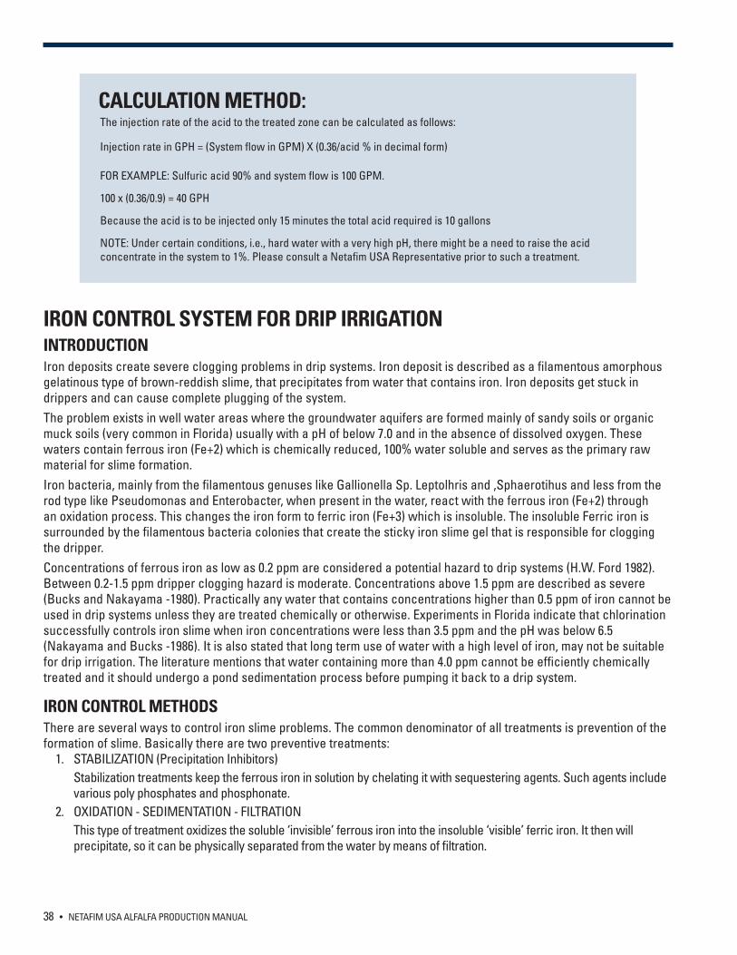
38 • NETAFIM USA ALFALFA PRODUCTION MANUAL
CALCULATION METHOD:The injection rate of the acid to the treated zone can be calculated as follows:
Injection rate in GPH = (System flow in GPM) X (0.36/acid % in decimal form)
FOR EXAMPLE: Sulfuric acid 90% and system flow is 100 GPM.
100 x (0.36/0.9) = 40 GPH
Because the acid is to be injected only 15 minutes the total acid required is 10 gallons
NOTE: Under certain conditions, i.e., hard water with a very high pH, there might be a need to raise the acid concentrate in the system to 1%. Please consult a Netafim USA Representative prior to such a treatment.
IRON CONTROL SYSTEM FOR DRIP IRRIGATION INTRODUCTION Iron deposits create severe clogging problems in drip systems. Iron deposit is described as a filamentous amorphous gelatinous type of brown-reddish slime, that precipitates from water that contains iron. Iron deposits get stuck in drippers and can cause complete plugging of the system. The problem exists in well water areas where the groundwater aquifers are formed mainly of sandy soils or organic muck soils (very common in Florida) usually with a pH of below 7.0 and in the absence of dissolved oxygen. These waters contain ferrous iron (Fe+2) which is chemically reduced, 100% water soluble and serves as the primary raw material for slime formation. Iron bacteria, mainly from the filamentous genuses like Gallionella Sp. Leptolhris and ,Sphaerotihus and less from the rod type like Pseudomonas and Enterobacter, when present in the water, react with the ferrous iron (Fe+2) through an oxidation process. This changes the iron form to ferric iron (Fe+3) which is insoluble. The insoluble Ferric iron is surrounded by the filamentous bacteria colonies that create the sticky iron slime gel that is responsible for clogging the dripper. Concentrations of ferrous iron as low as 0.2 ppm are considered a potential hazard to drip systems (H.W. Ford 1982). Between 0.2-1.5 ppm dripper clogging hazard is moderate. Concentrations above 1.5 ppm are described as severe (Bucks and Nakayama -1980). Practically any water that contains concentrations higher than 0.5 ppm of iron cannot be used in drip systems unless they are treated chemically or otherwise. Experiments in Florida indicate that chlorination successfully controls iron slime when iron concentrations were less than 3.5 ppm and the pH was below 6.5 (Nakayama and Bucks -1986). It is also stated that long term use of water with a high level of iron, may not be suitable for drip irrigation. The literature mentions that water containing more than 4.0 ppm cannot be efficiently chemically treated and it should undergo a pond sedimentation process before pumping it back to a drip system.
IRON CONTROL METHODSThere are several ways to control iron slime problems. The common denominator of all treatments is prevention of the formation of slime. Basically there are two preventive treatments:
1. STABILIZATION (Precipitation Inhibitors) Stabilization treatments keep the ferrous iron in solution by chelating it with sequestering agents. Such agents include
various poly phosphates and phosphonate. 2. OXIDATION - SEDIMENTATION - FILTRATION This type of treatment oxidizes the soluble ‘invisible’ ferrous iron into the insoluble ‘visible’ ferric iron. It then will
precipitate, so it can be physically separated from the water by means of filtration.
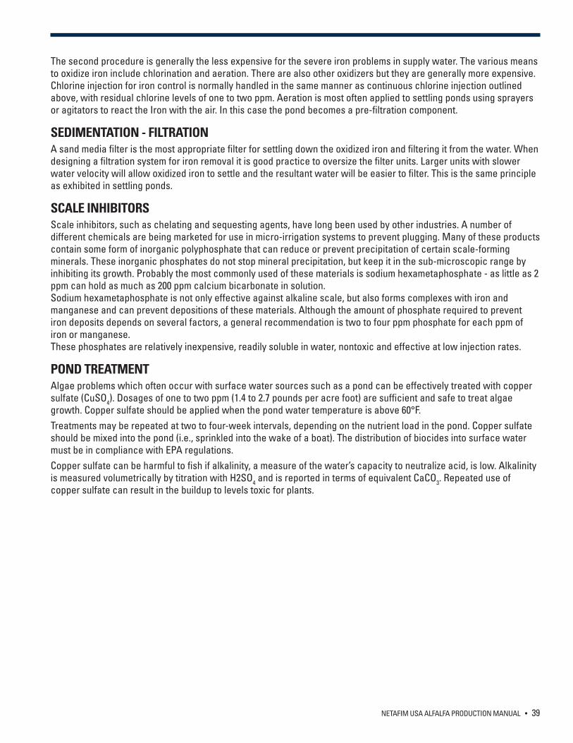
NETAFIM USA ALFALFA PRODUCTION MANUAL • 39
The second procedure is generally the less expensive for the severe iron problems in supply water. The various means to oxidize iron include chlorination and aeration. There are also other oxidizers but they are generally more expensive. Chlorine injection for iron control is normally handled in the same manner as continuous chlorine injection outlined above, with residual chlorine levels of one to two ppm. Aeration is most often applied to settling ponds using sprayers or agitators to react the Iron with the air. In this case the pond becomes a pre-filtration component.
SEDIMENTATION - FILTRATION A sand media filter is the most appropriate filter for settling down the oxidized iron and filtering it from the water. When designing a filtration system for iron removal it is good practice to oversize the filter units. Larger units with slower water velocity will allow oxidized iron to settle and the resultant water will be easier to filter. This is the same principle as exhibited in settling ponds.
SCALE INHIBITORSScale inhibitors, such as chelating and sequesting agents, have long been used by other industries. A number of different chemicals are being marketed for use in micro-irrigation systems to prevent plugging. Many of these products contain some form of inorganic polyphosphate that can reduce or prevent precipitation of certain scale-forming minerals. These inorganic phosphates do not stop mineral precipitation, but keep it in the sub-microscopic range by inhibiting its growth. Probably the most commonly used of these materials is sodium hexametaphosphate - as little as 2 ppm can hold as much as 200 ppm calcium bicarbonate in solution. Sodium hexametaphosphate is not only effective against alkaline scale, but also forms complexes with iron and manganese and can prevent depositions of these materials. Although the amount of phosphate required to prevent iron deposits depends on several factors, a general recommendation is two to four ppm phosphate for each ppm of iron or manganese. These phosphates are relatively inexpensive, readily soluble in water, nontoxic and effective at low injection rates.
POND TREATMENTAlgae problems which often occur with surface water sources such as a pond can be effectively treated with copper sulfate (CuSO4). Dosages of one to two ppm (1.4 to 2.7 pounds per acre foot) are sufficient and safe to treat algae growth. Copper sulfate should be applied when the pond water temperature is above 60°F. Treatments may be repeated at two to four-week intervals, depending on the nutrient load in the pond. Copper sulfate should be mixed into the pond (i.e., sprinkled into the wake of a boat). The distribution of biocides into surface water must be in compliance with EPA regulations. Copper sulfate can be harmful to fish if alkalinity, a measure of the water’s capacity to neutralize acid, is low. Alkalinity is measured volumetrically by titration with H2SO4 and is reported in terms of equivalent CaCO3. Repeated use of copper sulfate can result in the buildup to levels toxic for plants.

40 • NETAFIM USA ALFALFA PRODUCTION MANUAL
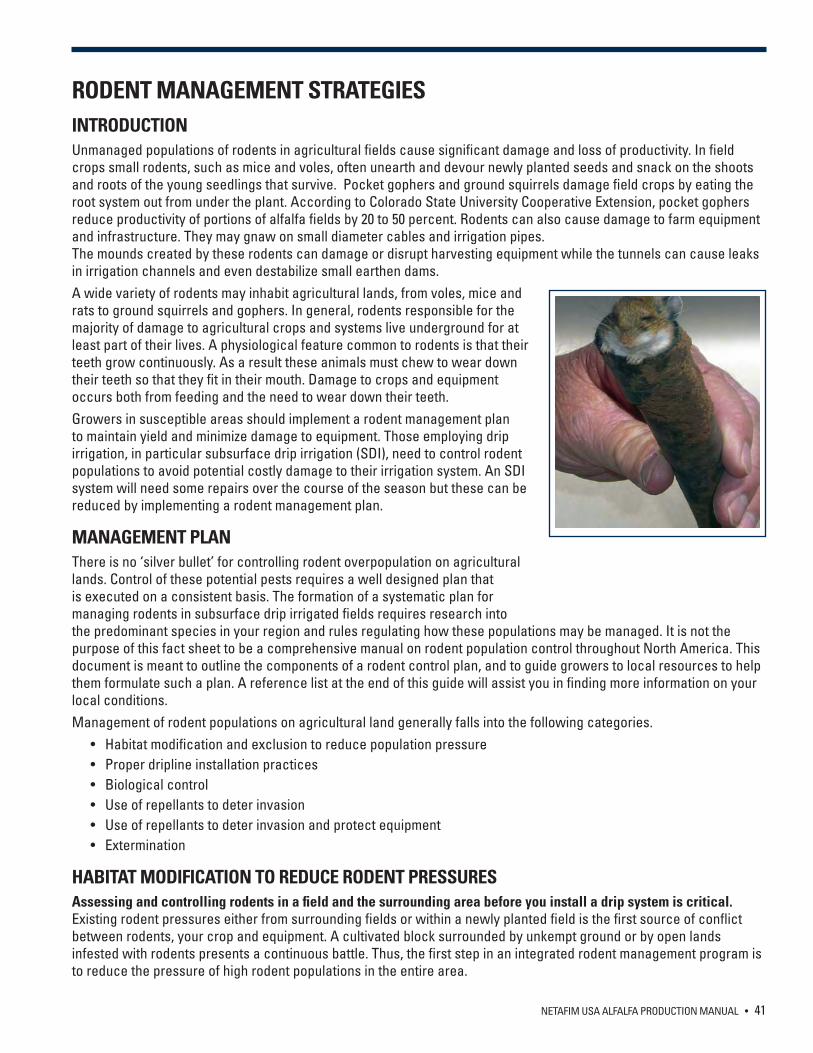
NETAFIM USA ALFALFA PRODUCTION MANUAL • 41
RODENT MANAGEMENT STRATEGIES INTRODUCTIONUnmanaged populations of rodents in agricultural fields cause significant damage and loss of productivity. In field crops small rodents, such as mice and voles, often unearth and devour newly planted seeds and snack on the shoots and roots of the young seedlings that survive. Pocket gophers and ground squirrels damage field crops by eating the root system out from under the plant. According to Colorado State University Cooperative Extension, pocket gophers reduce productivity of portions of alfalfa fields by 20 to 50 percent. Rodents can also cause damage to farm equipment and infrastructure. They may gnaw on small diameter cables and irrigation pipes. The mounds created by these rodents can damage or disrupt harvesting equipment while the tunnels can cause leaks in irrigation channels and even destabilize small earthen dams.A wide variety of rodents may inhabit agricultural lands, from voles, mice and rats to ground squirrels and gophers. In general, rodents responsible for the majority of damage to agricultural crops and systems live underground for at least part of their lives. A physiological feature common to rodents is that their teeth grow continuously. As a result these animals must chew to wear down their teeth so that they fit in their mouth. Damage to crops and equipment occurs both from feeding and the need to wear down their teeth.Growers in susceptible areas should implement a rodent management plan to maintain yield and minimize damage to equipment. Those employing drip irrigation, in particular subsurface drip irrigation (SDI), need to control rodent populations to avoid potential costly damage to their irrigation system. An SDI system will need some repairs over the course of the season but these can be reduced by implementing a rodent management plan.
MANAGEMENT PLANThere is no ‘silver bullet’ for controlling rodent overpopulation on agricultural lands. Control of these potential pests requires a well designed plan that is executed on a consistent basis. The formation of a systematic plan for managing rodents in subsurface drip irrigated fields requires research into the predominant species in your region and rules regulating how these populations may be managed. It is not the purpose of this fact sheet to be a comprehensive manual on rodent population control throughout North America. This document is meant to outline the components of a rodent control plan, and to guide growers to local resources to help them formulate such a plan. A reference list at the end of this guide will assist you in finding more information on your local conditions.Management of rodent populations on agricultural land generally falls into the following categories. • Habitat modification and exclusion to reduce population pressure • Proper dripline installation practices • Biological control • Use of repellants to deter invasion • Use of repellants to deter invasion and protect equipment • Extermination
HABITAT MODIFICATION TO REDUCE RODENT PRESSURESAssessing and controlling rodents in a field and the surrounding area before you install a drip system is critical. Existing rodent pressures either from surrounding fields or within a newly planted field is the first source of conflict between rodents, your crop and equipment. A cultivated block surrounded by unkempt ground or by open lands infested with rodents presents a continuous battle. Thus, the first step in an integrated rodent management program is to reduce the pressure of high rodent populations in the entire area.
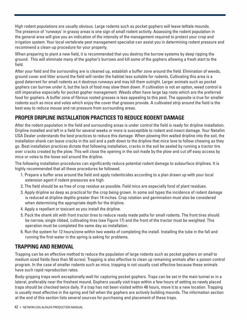
42 • NETAFIM USA ALFALFA PRODUCTION MANUAL
High rodent populations are usually obvious. Large rodents such as pocket gophers will leave telltale mounds. The presence of ‘runways’ in grassy areas is one sign of small rodent activity. Assessing the rodent population in the general area will give you an indication of the intensity of the management required to protect your crop and irrigation system. Your local vertebrate pest management specialist can assist you in determining rodent pressure and recommend a clean-up procedure for your property. When preparing to plant a new field, it is recommended that you destroy the burrow systems by deep ripping the ground. This will eliminate many of the gopher’s burrows and kill some of the gophers allowing a fresh start to the field.After your field and the surrounding are is cleaned up, establish a buffer zone around the field. Elimination of weeds, ground cover and litter around the field will render the habitat less suitable for rodents. Cultivating this area is a good deterrent for small rodents as it destroys runways and may kill them outright. Larger animals such as pocket gophers can burrow under it, but the lack of food may slow them down. If cultivation is not an option, weed control is still imperative especially for pocket gopher management. Weeds often have large tap roots which are the preferred food for gophers. A buffer zone of fibrous rooted grasses is less appealing to this pest. The opposite is true for smaller rodents such as mice and voles which enjoy the cover that grasses provide. A cultivated strip around the field is the best way to reduce mouse and rat pressure from surrounding areas.
PROPER DRIPLINE INSTALLATION PRACTICES TO REDUCE RODENT DAMAGE After the rodent population in the field and surrounding areas is under control the field is ready for dripline installation. Dripline installed and left in a field for several weeks or more is susceptible to rodent and insect damage. Your Netafim USA Dealer understands the best practices to reduce this damage. When plowing thin walled dripline into the soil, the installation shank can leave cracks in the soil and a path down to the dripline that mice love to follow chewing as they go. Best installation practices dictate that following installation, cracks in the soil be sealed by running a tractor tire over cracks created by the plow. This will close the opening in the soil made by the plow and cut off easy access by mice or voles to the loose soil around the dripline.The following installation procedures can significantly reduce potential rodent damage to subsurface driplines. It is highly recommended that all these procedures be followed. 1. Prepare a buffer area around the field and apply rodenticides according to a plan drawn up with your local
extension agent if rodent pressures are high. 2. The field should be as free of crop residue as possible. Field mice are especially fond of plant residues. 3. Apply dripline as deep as practical for the crop being grown. In some soil types the incidence of rodent damage
is reduced at dripline depths greater than 14 inches. Crop rotation and germination must also be considered when determining the appropriate depth for the dripline.
4. Apply a repellant or toxicant as you install the dripline. 5. Pack the shank slit with front tractor tires to reduce ready made paths for small rodents. The front tires should
be narrow, single ribbed, cultivating tires (see Figure 17) and the front of the tractor must be weighted. This operation must be completed the same day as installation.
6. Run the system for 12 hours/zone within two weeks of completing the install. Installing the tube in the fall and running the first water in the spring is asking for problems.
TRAPPING AND REMOVALTrapping can be an effective method to reduce the population of large rodents such as pocket gophers on small to medium sized fields (less than 50 acres). Trapping is also effective to clean up remaining animals after a poison control program. In the case of smaller rodents such as mice, trapping is not usually cost effective because these animals have such rapid reproduction rates. Body-gripping traps work exceptionally well for capturing pocket gophers. Traps can be set in the main tunnel or in a lateral, preferably near the freshest mound. Gophers usually visit traps within a few hours of setting so newly placed traps should be checked twice daily. If a trap has not been visited within 48 hours, move it to a new location. Trapping is usually most effective in the spring and fall when the gophers are actively building mounds. The information section at the end of this section lists several sources for purchasing and placement of these traps.
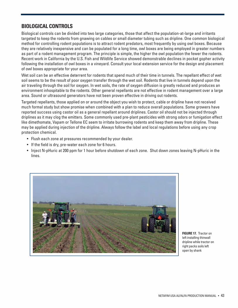
NETAFIM USA ALFALFA PRODUCTION MANUAL • 43
FIGURE 17. Tractor on left installing thinwall dripline while tractor on right packs soils left open by shank
BIOLOGICAL CONTROLSBiological controls can be divided into two large categories, those that affect the population-at-large and irritants targeted to keep the rodents from gnawing on cables or small diameter tubing such as dripline. One common biological method for controlling rodent populations is to attract rodent predators, most frequently by using owl boxes. Because they are relatively inexpensive and can be populated for a long time, owl boxes are being employed in greater numbers as part of a rodent management program. The principle is simple, the higher the owl population the fewer the rodents. Recent work in California by the U.S. Fish and Wildlife Service showed demonstrable declines in pocket gopher activity following the installation of owl boxes in a vineyard. Consult your local extension service for the design and placement of owl boxes appropriate for your area.Wet soil can be an effective deterrent for rodents that spend much of their time in tunnels. The repellant effect of wet soil seems to be the result of poor oxygen transfer through the wet soil. Rodents that live in tunnels depend upon the air traveling through the soil for oxygen. In wet soils, the rate of oxygen diffusion is greatly reduced and produces an environment inhospitable to the rodents. Other general repellants are not effective in rodent management over a large area. Sound or ultrasound generators have not been proven effective in driving out rodents. Targeted repellants, those applied on or around the object you wish to protect, cable or dripline have not received much formal study but show promise when combined with a plan to reduce overall populations. Some growers have reported success using castor oil as a general repellant around driplines. Castor oil should not be injected through driplines as it may clog the emitters. Some commonly used pre-plant pesticides with strong odors or fumigation effect like dimethomate, Vapam or Tellone EC seem to irritate burrowing rodents and keep them away from dripline. These may be applied during injection of the dripline. Always follow the label and local regulations before using any crop protection chemical. • Flush each zone at pressures recommended by your dealer. • If the field is dry, pre-water each zone for 6 hours. • Inject N-pHuric at 200 ppm for 1 hour before shutdown of each zone. Shut down zones leaving N-pHuric in the
lines.
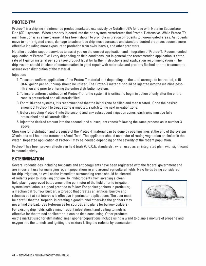
44 • NETAFIM USA ALFALFA PRODUCTION MANUAL
PROTEC-T™Protec-T is a dripline maintenance product marketed exclusively by Netafim USA for use with Netafim Subsurface Drip (SDI) systems. When properly injected into the drip system, vertebrates find Protec-T offensive. While Protec-T’s main function is as a line cleaner, it has been shown to promote migration of rodents to non-irrigated areas. As rodents move to non-irrigated areas, damage to subsurface driplines decreases and standard control practices become more effective including more exposure to predation from owls, hawks, and other predators. Netafim provides support services to assist you on the correct application and integration of Protec-T. Recommended application of Protec-T will vary depending on field conditions, but in general, the recommended application is at the rate of 1 gallon material per acre (see product label for further instructions and application recommendations). The drip system should be clear of contamination, in good repair with no breaks and properly flushed prior to treatment to assure even distribution of the material.Injection: 1. To assure uniform application of the Protec-T material and depending on the total acreage to be treated, a 15-
30-60 gallon per hour pump should be utilized. The Protec-T material should be injected into the mainline post-filtration and prior to entering the entire distribution system.
2. To insure uniform distribution of Protec-T thru the system it is critical to begin injection of only after the entire zone is pressurized and all laterals filled.
3. For multi-zone systems, it is recommended that the initial zone be filled and then treated. Once the desired amount of Protec-T to treat a zone is injected, switch to the next irrigation zone.
4. Before injecting Protec-T into the second and any subsequent irrigation zones, each zone must be fully pressurized and all laterals filled.
5. Inject the desired amount into the second (and subsequent zones) following the same process as in number 3 above.
Checking for distribution and presence of the Protec-T material can be done by opening lines at the end of the system 30 minutes to 1 hour into treatment (Smell Test). The applicator should note odor of rotting vegetation or similar in the water. Repeated application of Protec-T may be needed depending on the severity of the rodent population.
Protec-T has been proven effective in field trials (U.C.C.E. standards), when used as an integrated plan, with significant in mound activity.
EXTERMINATIONSeveral rodenticides including toxicants and anticoagulants have been registered with the federal government and are in current use for managing rodent populations in and around agricultural fields. New fields being considered for drip irrigation, as well as the immediate surrounding areas should be cleared of rodents prior to installing dripline. To inhibit rodents from invading a clean field placing approved bates around the perimeter of the field prior to irrigation system installation is a good practice to follow. For pocket gophers in particular, a mechanical ‘burrow builder’, a torpedo that creates an artificial burrow and releases bait at set intervals is effective in perimeter applications. The user must be careful that the ‘torpedo’ is creating a good tunnel otherwise the gophers may never find the bait. (See References for sources and plans for burrow builders). For existing drip fields with a minor rodent infestation, hand baiting tunnels is effective for the trained applicator but can be time consuming. Other products on the market used for eliminating small gopher populations include using a wand to pump a mixture of propane and oxygen into the tunnels and igniting the mixture killing the rodents by concussion.
NETAFIM USA ALFALFA PRODUCTION MANUAL • 45
RODENT MANAGEMENT ACTION PLANAn integrated approach must be taken to reduce rodent damage to crops and equipment. This plan must involve reducing acceptable habitats for rodents close to the field and may involve trapping or poisoning to control active populations. In addition, the dripline itself can be protected using the repellant effect of some pesticides and slightly acidifying the soil around the lines.Fall and spring are the most active time for rodents and they seem to be the worst seasons for damage - thus any management program must focus on these seasons. Do not underestimate the wealth of reference materials and the help of local extension agents and pest control specialists. Many growers have implemented successful plans for rodent management on their fields - protecting the investment in their irrigation system and improving yields. To be effective, any rodent control plan must be diligent and consistent in a time frame determined by the extent of the rodent pressure in the general area.
46 • NETAFIM USA ALFALFA PRODUCTION MANUAL
REFERENCESThe following websites offer excellent information on the management of pocket gophers and mice and provide lists of additional resources.
http://www.ext.colostate.edu/PUBS/NATRES/06515.html
‘Developing an IPM Program for Controlling Pocket Gophers in Alfalfa’ by Dr. Roger Baldwin, UCCE Wildlife Pest Management Advisor, California Statewide IPM Programhttp://alfalfa.ucdavis.edu/+symposium/proceedings/2010/10-151.pdf
http://extension.usu.edu/files/publications/publication/NR_WD_005.pdf
www.icwdm.org/Publications/WildlifePublications.asp
Internet center for Wildlife Damage Management - an extensive site for all types of human wildlife interactions. Site includes an excellent publication on pocket gophers with an extensive university reference section.www.berrymaninstitute.org
Concentrates on human wildlife interaction. Excellent article on Pocket Gophers.http://www.ipm.ucdavis.edu/PMG/crops-agriculture.html
Washington State University list of links to vertebrate pest control siteswww.snohomish.wsu.edu/garden/verturl.htm
SELECTED REFERENCESClark, J.P., ed. Vertebrate pest control handbook, 4th Edition. State of California, Dept. of Food and Agic., Division of Plant Industry, Integrated Pest control Branch. 1994
Hygnstrom, S.E., R.M. Timm and G.E. Larson, eds. Prevention and Control of Wildlife Damage. University of Nebraska, Institute of Agric. and Natural Resources; USDA/APHIS, ADC and Great Plains Agric. Council, Wildlife Committee.1994.
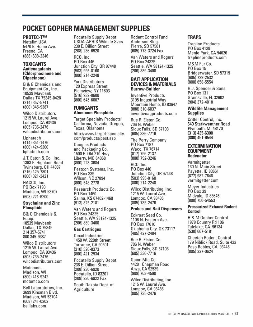
NETAFIM USA ALFALFA PRODUCTION MANUAL • 47
POCKET GOPHER MANAGEMENT SUPPLIESPROTEC-T™Netafim USA5470 E. Home Ave.Fresno, CA(888) 638-2346
TOXICANTSAnticoagulants (Chlorphacinone and Dipacinone)B & G Chemicals and Equipment Co., Inc.10539 MaybankDallas TX 75345-0428(214) 357-5741(800) 345-9387Wilco Distributors1215 W. Laurel Ave.Lompoc, CA 93436(805) 735-2476wilcodistributors.comLiphatech(414) 351-1476(800) 424-9300liphatech.comJ.T. Eaton & Co., Inc.1393 E. Highland RoadTwinsburg, OH 44087(216) 425-7801(800) 321-3421HACCO, Inc.PO Box 7190Madison, WI 53707(608) 221-6200Strychnine and Zinc PhosphideB& G Chemicals & Equip.10539 MaybankDallas, TX 75345214 357-5741800 345-9387 Wilco Distributors1215 W. Laural Ave.Lompoc, CA 93436(805) 735-2476wilcodistributors.comMotomcoMadison, WI(800) 418-9242motomco.comBell Laboratories, Inc.3699 Kinsman Blvd.Madison, WI 53704(608) 241-0202belllabs.com
Pocatello Supply DepotUSDA-APHIS Wildlife Svcs238 E. Dillion Street(208) 236-6920RCO, Inc.PO Box 446Junction City, OR 97448(503) 995-8160(800) 214-2248York Distributors120 Express StreetPlainview, NY 11803(516) 932-0600(800) 645-6007
FUMIGANTSAluminum PhosphideTarget Specialty ProductsCalifornia, Nevada, Oregon, Texas, Oklahomahttp://www.target-specialty.com/products/pest.aspDouglas Productsand Packaging Co.1500 E. Old 210 HwyLiberty, MO 64068(800) 223-3684Pestcon Systems, Inc.PO Box 339Wilson, NC 27894(800) 548-2778Research Products Co.PO Box 1460Salina, KS 67402-1460(913) 825-2181Van Waters and RogersPO Box 24325Seattle, WA 98124-1325(206) 889-3400Gas CartridgesDexol Industries1450 W. 228th StreetTorrance, CA 90501(310) 326-8373 (800) 421-2934Pocatello Supply Depot238 E. Dillion Street(208) 236-6920Pocatello, ID 83201(208) 236-6922 FaxSouth Dakota Dept. of Agriculture
Rodent Control FundAnderson Bldg.Pierre, SD 57501(605) 773-3724 FaxVan Waters and RogersPO Box 24325Seattle, WA 98124-1325(206) 889-3400
BAIT APPLICATIONDEVICES & MATERIALSBurrow-BuilderInventive Products3195 Industrial WayMountain Home, ID 83647(888) 310-6037inventiveagproducts.comRue R. Elston Co.706 N. WeberSioux Falls, SD 57103(605) 336-7716The Perry CompanyPO Box 7187Waco, TX 76714(817) 756-2137(800) 792-3246RCO, Inc.PO Box 446Junction City, OR 97448(503) 995-8160(800) 214-2248Wilco Distributing, Inc.1215 W. Laural Ave.Lompoc, CA 93436(805) 735-2476Probes and Bait DispensersEckroat Seed Co.1106 N. Eastern Ave.PO Box 17610Oklahoma City, OK 73117(405) 427-2484Rue R. Elston Co.706 N. WeberSioux Falls, SD 57103(605) 336-7716Quinn Mfg Co.44201 Chapman RoadAnza, CA 92539(909) 763-4590Wilco Distributing, Inc.1215 W. Laural Ave.Lompoc, CA 93436(805) 735-2476
TRAPSTrapline ProductsPO Box 4128Menlo Park, CA 94026traplineproducts.comM&M Fur Co.PO Box 15Bridgerwater, SD 57319(605) 729-2532(800) 658-5554H.J. Spencer & SonsPO Box 131Grainsville, FL 32602(904) 372-4018Wildlife Management SuppliesCritter Control, Inc.640 Starkweather RoadPlymouth, MI 48170(313) 435-6300(800) 451-6544
EXTERMINATION EQUIPMENTRodenatorVarmitgetter130 N. Main StreetPayette, ID 83661(877) 982-7648varmitgetter.comMeyer IndustriesPO Box 39Midvale, ID 83645(800) 750-54553Pressurized Exhaust Rodent ControlH & M Gopher Control1979 Country Rd 106Tulelake, CA 96134(530) 667-5181Cheetah Rodent Control179 Niblick Road, Suite 422Paso Robles, CA 93446(805) 227-0624

NETAFIM USA5470 E. Home Ave.Fresno, CA 93727CS 888 638 2346www.netafimusa.com
ALFALFA MANUAL 03/14