al3909 - hd mouldflow report 20170606.ppt - autodesk · moldflow analysis report case al3909 _...
TRANSCRIPT

Moldflow Analysis ReportMoldflow Analysis ReportMoldflow Analysis ReportMoldflow Analysis Report
CASE CASE CASE CASE AL3909 _ 20170606AL3909 _ 20170606AL3909 _ 20170606AL3909 _ 20170606
2020202017.0617.0617.0617.06

� To analysis original design, cooling and check flow , warp.
ANALYSIS AIMS
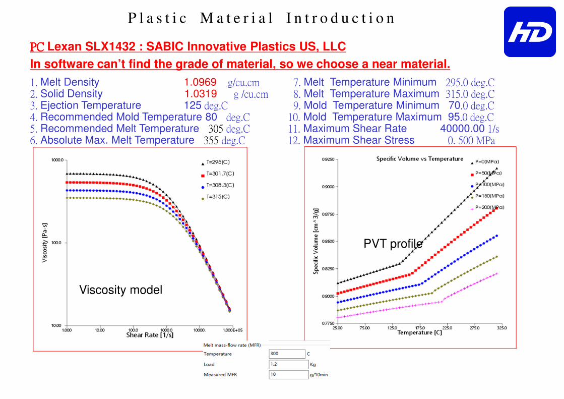
P l a s t i c M a t e r i a l I n t r o d u c t i o n
1. Melt Density 1.0969 g/cu.cm 2. Solid Density 1.0319 g /cu.cm 3. Ejection Temperature 125 deg.C 4. Recommended Mold Temperature 80 deg.C 5. Recommended Melt Temperature 305 deg.C 6. Absolute Max. Melt Temperature 355 deg.C
7. Melt Temperature Minimum 295.0 deg.C 8. Melt Temperature Maximum 315.0 deg.C 9. Mold Temperature Minimum 70.0 deg.C 10. Mold Temperature Maximum 95.0 deg.C 11. Maximum Shear Rate 40000.00 1/s 12. Maximum Shear Stress 0. 500 MPa
Viscosity model
PVT profile
PCPCPCPC Lexan SLX1432 : SABIC Innovative Plastics US, LLC
In software can’t find the grade of material, so we choose a near material.
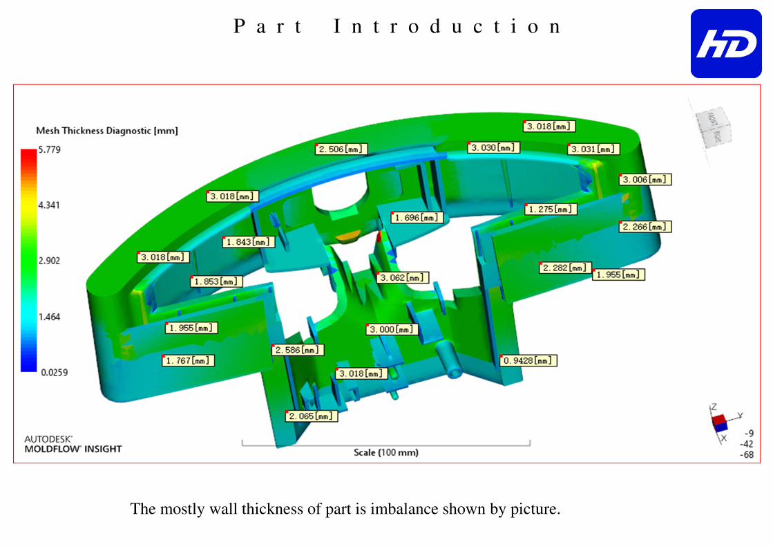
P a r t I n t r o d u c t i o n
The mostly wall thickness of part is imbalance shown by picture.

F e e d S y s t e m D e s i g n
1x1 cavities, two plates mold, Cold runner +sub gate, the size is shown by picture.
sub gate 1.5mm
Cold sprue 4-+mm
Cold runner 6mm
Cold runner 6mm
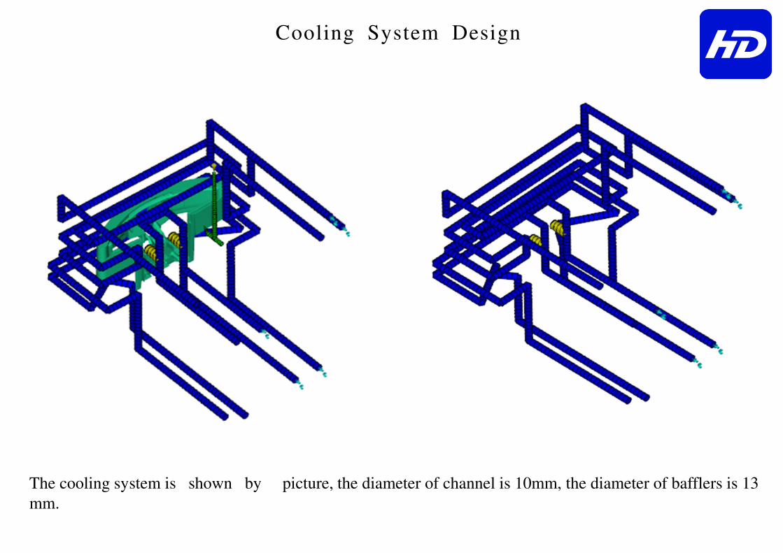
Cooling System Design
The cooling system is shown by picture, the diameter of channel is 10mm, the diameter of bafflers is 13
mm.
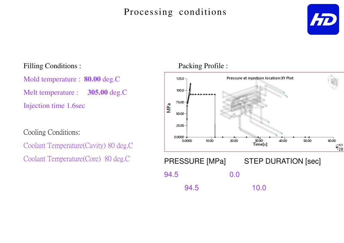
Processing condit ions
PRESSURE [MPa] STEP DURATION [sec]
94.5 0.0
94.5 10.0
Filling Conditions :
Mold temperature : 80.00 deg.C
Melt temperature : 305.00 deg.C
Injection time 1.6sec
Cooling Conditions:
Coolant Temperature(Cavity) 80 deg.C
Coolant Temperature(Core) 80 deg.C
Packing Profile :

Circuit coolant Temperature
The circuit coolant The circuit coolant The circuit coolant The circuit coolant temperature of part is balance shown by picture.temperature of part is balance shown by picture.temperature of part is balance shown by picture.temperature of part is balance shown by picture.
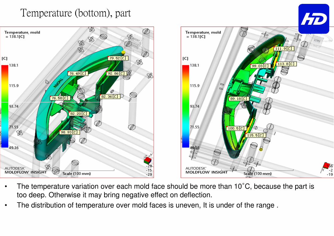
Temperature (bottom), part
• The temperature variation over each mold face should be more than 10°C, because the part is too deep. Otherwise it may bring negative effect on deflection.
• The distribution of temperature over mold faces is uneven, It is under of the range .
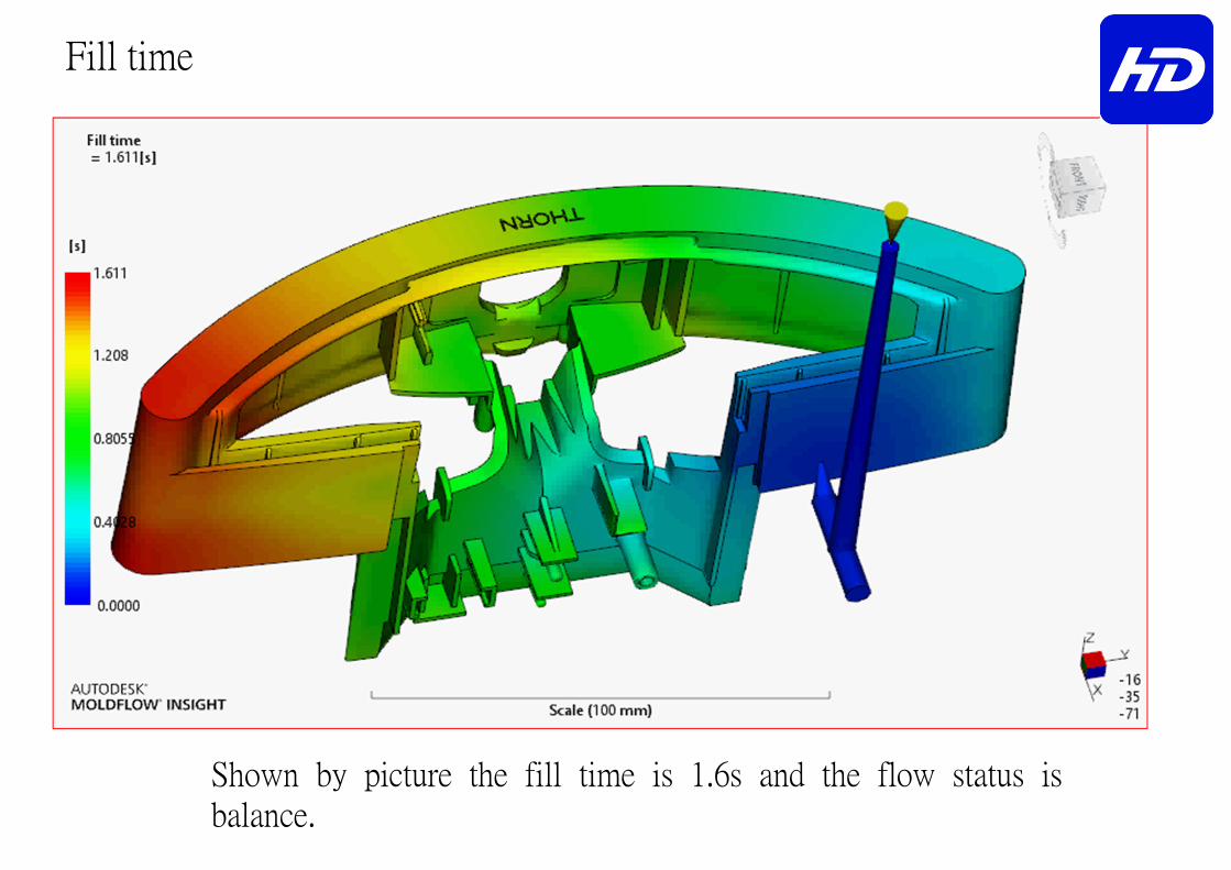
Fill time
Shown by picture the fill time is 1.6s and the flow status is
balance.
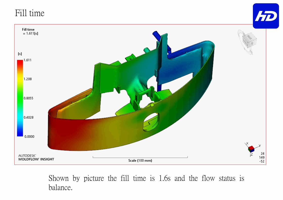
Fill time
Shown by picture the fill time is 1.6s and the flow status is
balance.
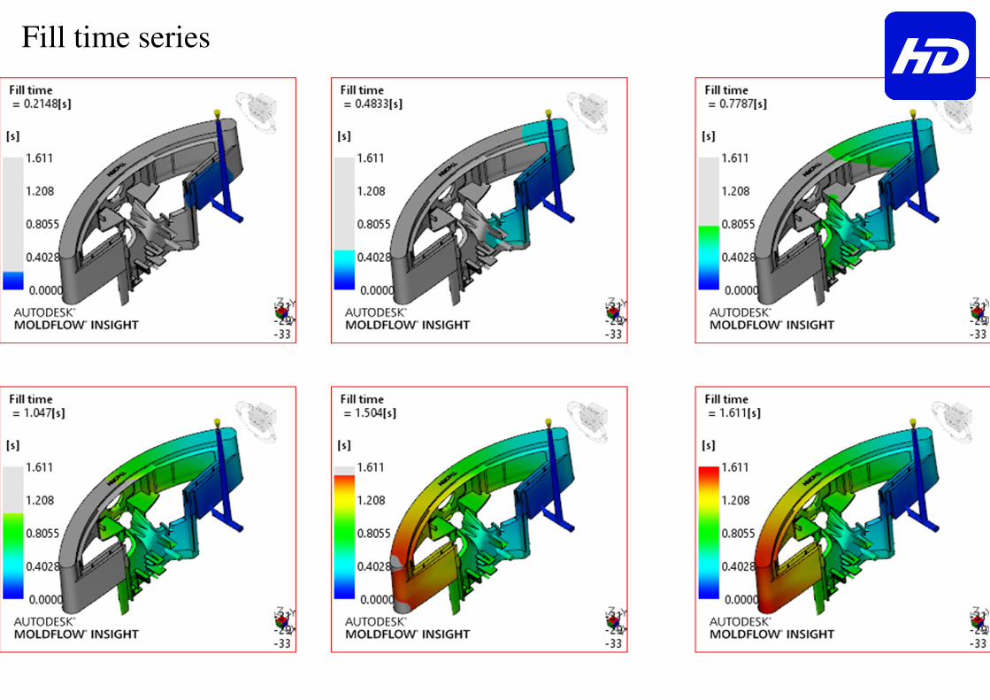
Fill time series
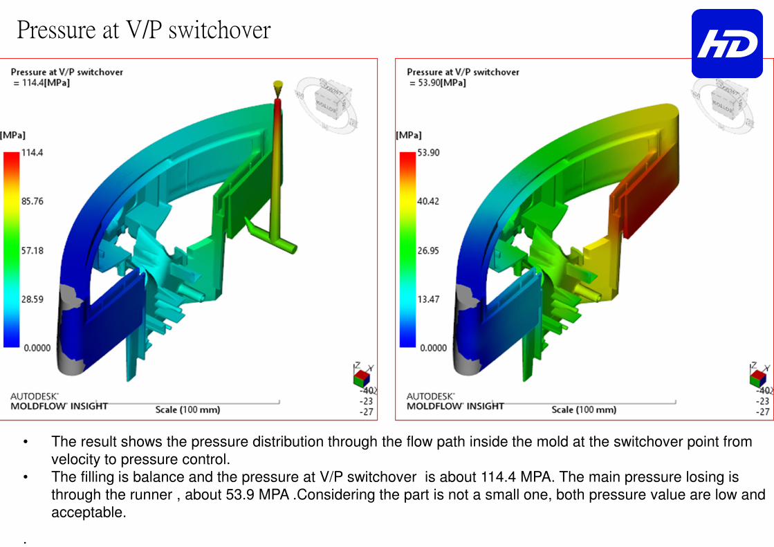
Pressure at V/P switchover
• The result shows the pressure distribution through the flow path inside the mold at the switchover point from
velocity to pressure control.
• The filling is balance and the pressure at V/P switchover is about 114.4 MPA. The main pressure losing is
through the runner , about 53.9 MPA .Considering the part is not a small one, both pressure value are low and
acceptable.
.

Temperature at flow front
Temperature at flow front is balance shown by picture.
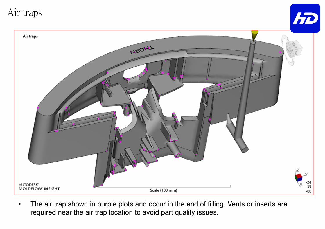
Air traps
• The air trap shown in purple plots and occur in the end of filling. Vents or inserts are
required near the air trap location to avoid part quality issues.
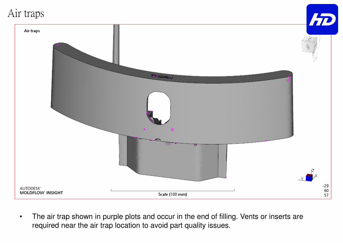
Air traps
• The air trap shown in purple plots and occur in the end of filling. Vents or inserts are
required near the air trap location to avoid part quality issues.

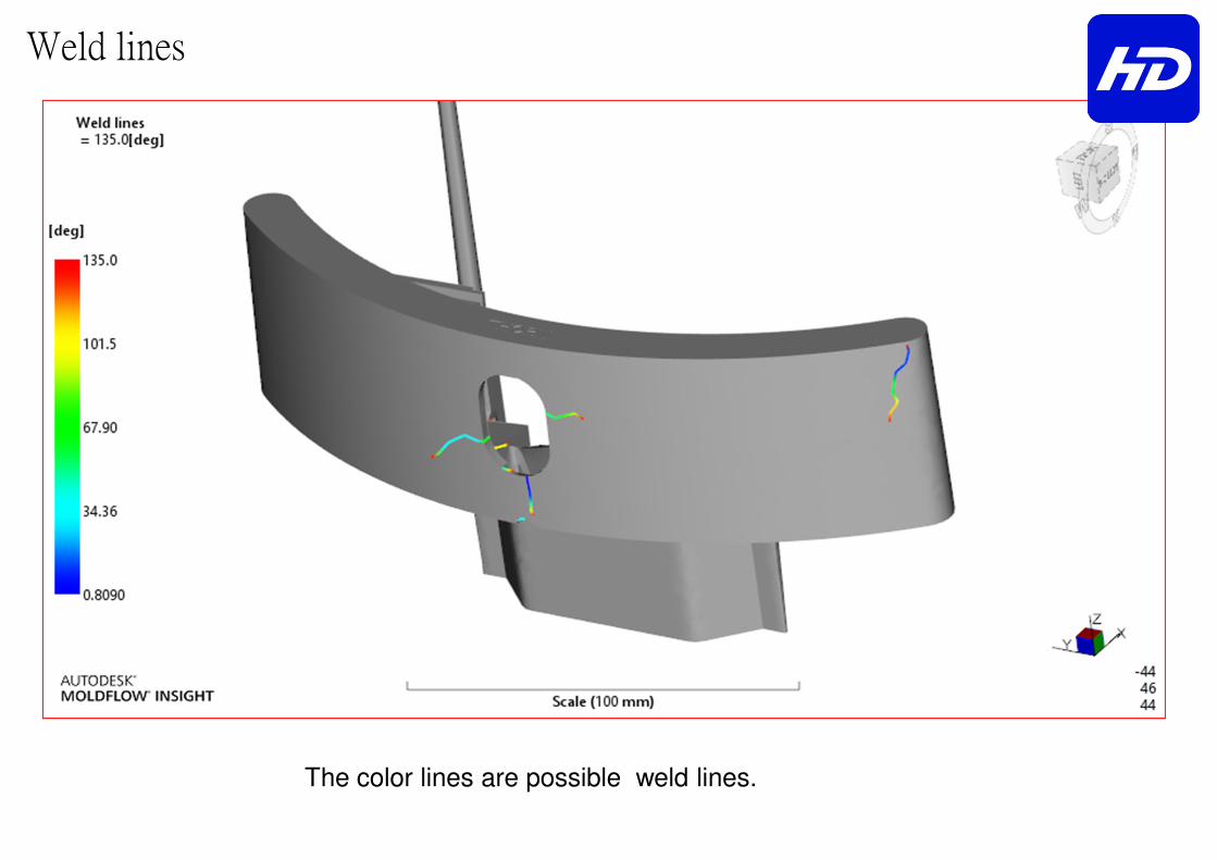
Weld lines
The color lines are possible weld lines.
Weld lines
The color lines are possible weld lines.
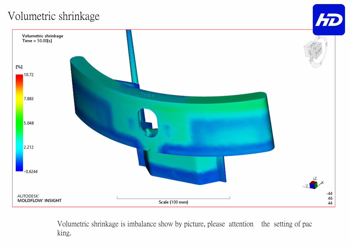
Volumetric shrinkage
Volumetric shrinkage is imbalance show by picture, please attention the setting of pac
king.
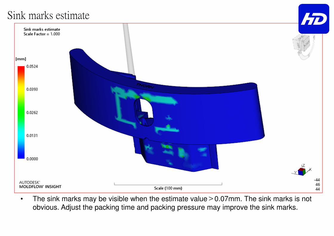
Sink marks estimate
• The sink marks may be visible when the estimate value>0.07mm. The sink marks is not obvious. Adjust the packing time and packing pressure may improve the sink marks.

Injection Pressure & Clamp Force
Pressure at injection location Clamp Force
Max.: 114.4MPa Max.: 61.2tonne

Frozen series
Finish cooling, close cycle.
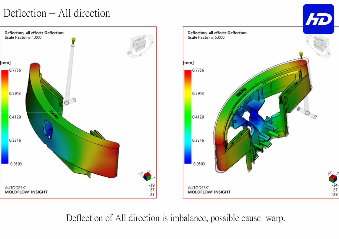
Deflection – All direction
Deflection of All direction is imbalance, possible cause warp.
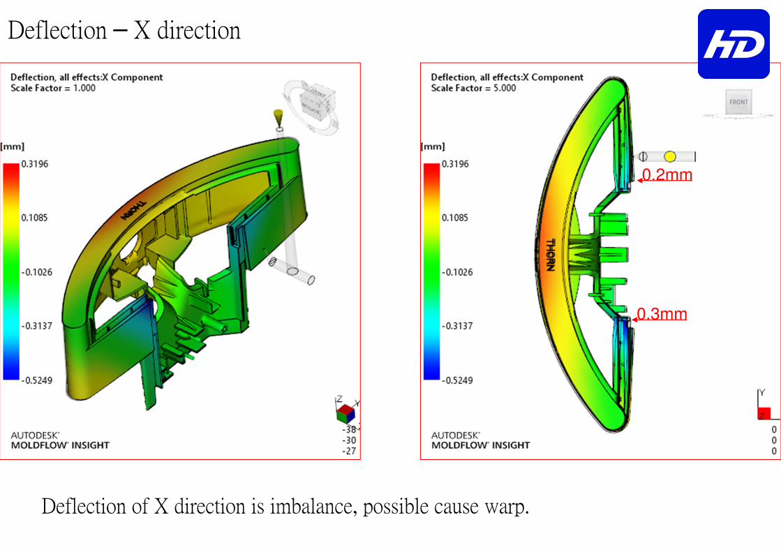
Deflection – X direction
Deflection of X direction is imbalance, possible cause warp.
0.3mm
0.2mm

Deflection – X direction
Deflection of X direction is imbalance, possible cause warp.
0.3mm
0.2mm
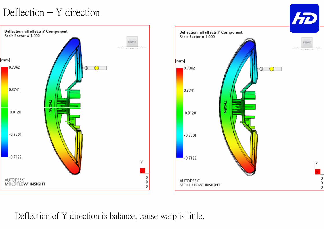
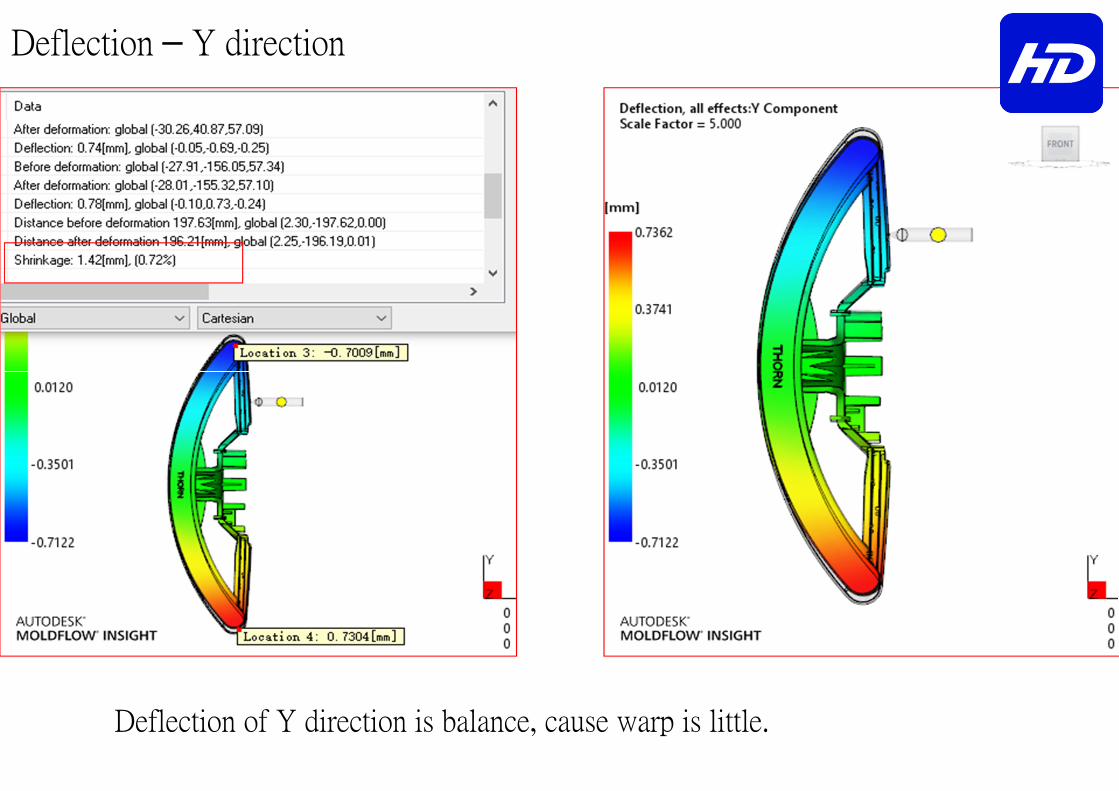
Deflection – Y direction
Deflection of Y direction is balance, cause warp is little.
Deflection – Y direction
Deflection of Y direction is balance, cause warp is little.
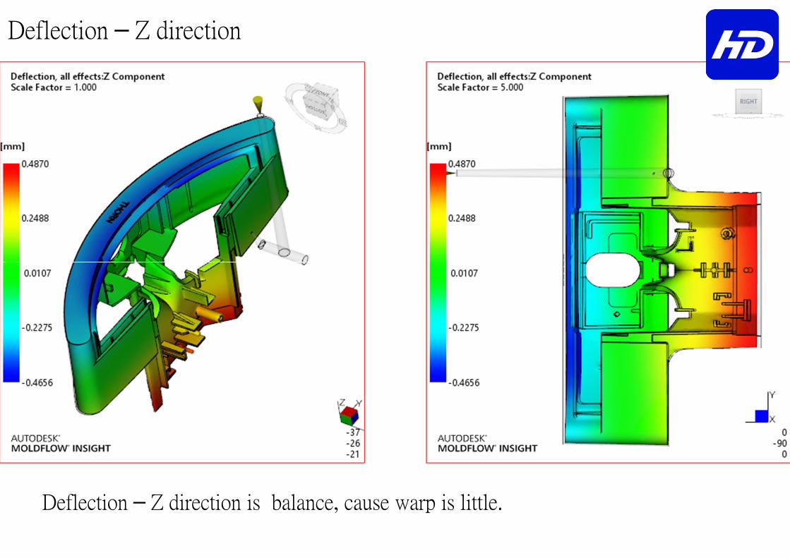
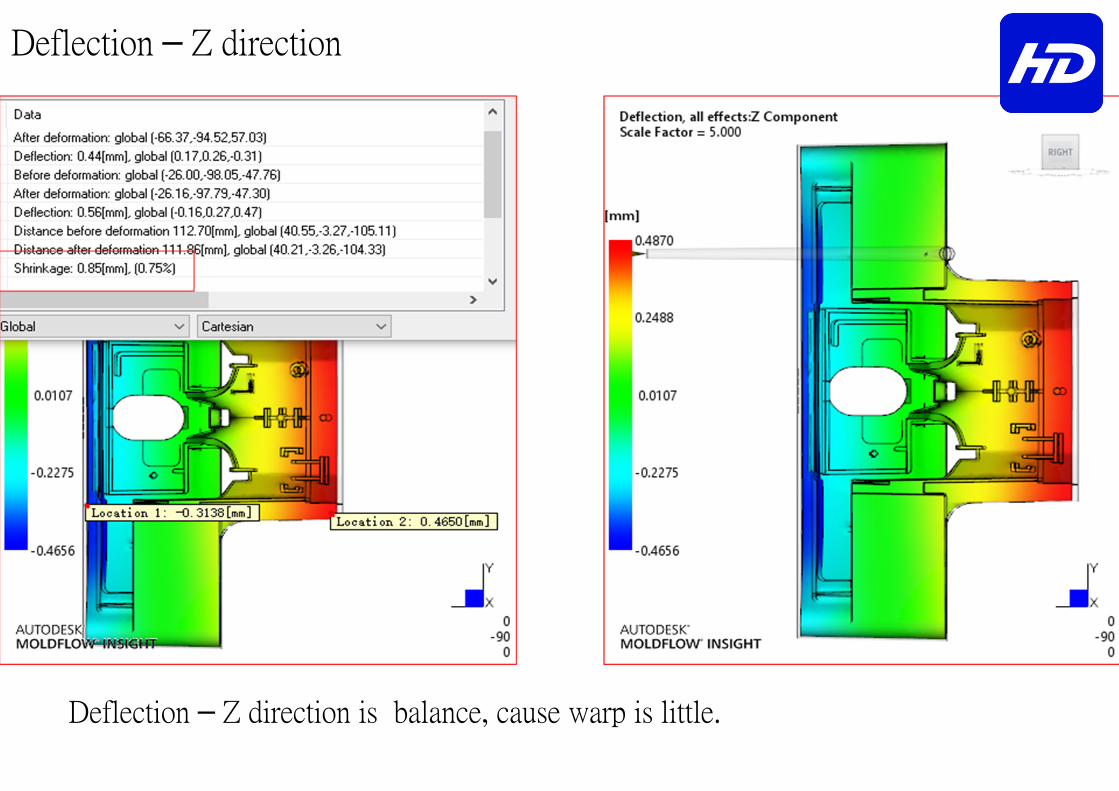
Deflection – Z direction
Deflection – Z direction is balance, cause warp is little.
Deflection – Z direction
Deflection – Z direction is balance, cause warp is little.
S u m m a r y
The results::::
� The flow status is balance, the injection and packing pressure is normal.
� The volumetric shrinkage is imbalance, please attention the setting of packing.
� Deflection of Y&Z direction is balance, cause warp is little. Deflec
tion of X direction is imbalance, possible cause warp.
� The project cycle time: 1.6 (filling)+ 24.4(cooling + packing) + 5.0 (open & eject & close) =31.0 sec.