airglow-solar spectrometer instrument (20–700 nm) aboard the san marco d/l satellite
TRANSCRIPT
Airglow-solar spectrometer instrument (20-700 nm)aboard the San Marco D/L satellite
G. Schmidtke, P. Seidl, and C. Wita
The ASSI experiment aboard the San Marco D/L aeronomy satellite will monitor the airglow, solar, and in-terplanetary radiations from the EUV through the visible spectral regions. Four spectrometers with solarpointing control cover this broad region using channels with eighteen overlapping wavelength ranges withspectral resolutions from 0.8 to 3.0 nm are adequate for aeronomy. Large dynamic ranges up to 1:1011 per-mit the measurement of faint airglow or interplanetary radiation and intense solar emissions with one andthe same instrument. Instrumental details such as the special optical design and calibration procedures arepresented in detail.
I. Introduction
The most important scientific goal of the Italian-American aeronomy satellite San Marco D/L is to studythe composition and structure of the equatorial ther-mosphere and its relationship to solar electromagneticradiation. In addition several important processesconcerning the dynamics of this interesting height re-gion will be investigated, e.g., the interhemispherictransport. The combination of scientific instrumentsas integrated into the spacecraft is well suited to acquiredata, the interpretation of which will significantlycontribute to better knowledge of upper atmosphericphenomena.
The satellite instrumentation consists of the (neutral)wind and temperature (WATI), the ion velocity (IVI),the electrical field (EFI), the drag balance (DBI), andthe solar-airglow spectrometer (ASSI) instruments.Densities will be derived from atmospheric drag analysis(ADA) of the spacecraft.
Of these instruments, the solar-airglow spectrometeris the only optical one. Among other qualities of ASSI,such as the broad spectral coverage from the extremeultraviolet (EUV) through the visible regions, the largedynamic range of 1:1011 enables the measurements of
G. Schmidtke is with Institut fr physikalische Messtechnik,Heidenhofstr. 8, D-7800 Freiburg, Federal Republic of Germany; theother authors are with Physikalisch-Technische Studien GmbH,Leinenweberstr. 16, D-7800 Freiburg, Federal Republic of Ger-many.
Received 23 July 1984.0003-6935/85/193206-08$02.00/0.© 1985 Optical Society of America.
solar, interplanetary, and airglow radiation with thesame instrument. Taking into account its capabilityof remote sensing from the earth's surface (in the visi-ble) through the various atmospheric layers up to theupper thermosphere (in the EUV), ASSI will contributea great deal to the satellite mission objectives.
II. Mission Goal of ASSI and its InstrumentalImplications
Within the scope of the San Marco satellite missionthe actual solar and airglow fluxes will be measured forthe integrated data evaluation of this internationalaeronomic program. The radiation components are ofa different nature posing specific requirements to theinstrument, e.g., with respect to precision and accuracy,temporal and spectral resolutions, pointing accuracy,and field of view.
One of the parameters to be monitored is the vari-ability of the solar flux below 300 nm being stronger atshorter wavelengths. 1" A precision (relative accuracy)of the measurements of better than 1% is required totrace these flux changes. In the same wavelength regionthe absolute accuracy of the fluxes determined shouldbe -20% for the shorter and 10% and less for the longerwavelengths.
The temporal resolution required is of the order ofminutes only, since solar flux changes of aeronomic in-terest occur during flares or events at larger time scales(solar rotation or solar cycle).
The spectral resolution of ASSI had to be adapted tothe signatures of the emissions stemming primarily fromatoms in the <130-nm EUV region. In most casesidentification of the important lines suffices for aero-nomy. For this purpose a spectral resolution betterthan 1 nm is required; it can become 1-2 nm between130 and 300 nm and 2-4 nm between 300 and 700 nm.
3206 APPLIED OPTICS / Vol. 24, No. 19 / 1 October 1985
Incident J{adiation
-X -zIncident Radiation
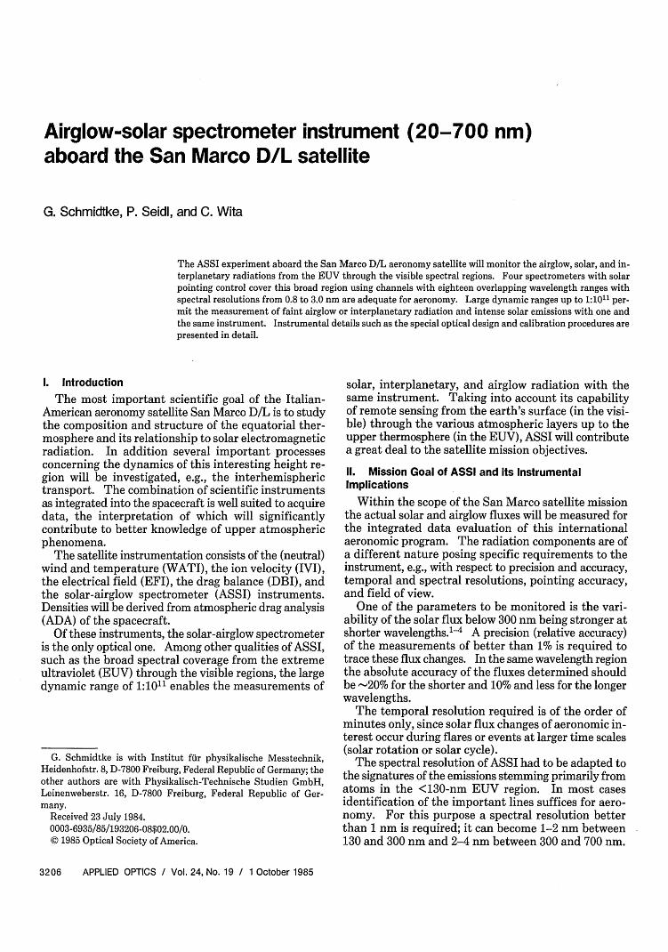
Fig. 1. Top and side view scheme of the San Marco satellite showing the position of ASSI A and ASSI B.
While the solar radiation is penetrating the upperatmosphere, say, above a height level of 300 km almostparallel, the atmospheric emissions are in general iso-tropic. To measure the first emission, the instrumentmust be pointed toward the sun with an accuracy of 10.For the airglow a field of view of typically some hun-dredths of a steradian should be provided to achieve themission goal.
The measurement of solar and airglow fluxes with thesame instrument implies a large dynamic range of, e.g.,up to 1:108 in the visible because of the large differencein the energies involved.
These and other (less important) requirements haveto be met taking into account the restrictions imposedby the rather small spinning spacecraft. The most se-rious one is the volume available followed by power,weight, telemetry, and data storage capability. In Sec.III the instrument will be described as it was designedto achieve the optical parameters adequate to meet themission goal within the tough satellite restrictions.
III. Instrumental Description
A. San Marco Spacecraft and ASSI
The ASSI design was strongly governed by thespherical spacecraft adapted to a Scout vehicle. Fol-lowing the rocket axis, a cylindrical volume within thesphere is reserved for the DBI experiment. The maincompartment for the other experiments lies betweentwo ringlike platforms 300 mm apart, where twocheeseboxlike spaces are available for ASSI A and B(Fig. 1).
The spin rate of San Marco will be 6 rpm with thespin axis parallel to the earth's axis in an equatorial250/800-km elliptical orbit of low inclination (3-5°).Taking account of the seasonal changes of the solarangle of incidence by 230, ASSI requires a solarpointing control to monitor the solar radiation. Thisis achieved in an autonomous way independently foreach of the two experiment boxes A and B.
Solar cells are attached to the spherical surface of the94-cm diam spacecraft. Since there is no solar panel,experimental energy consumption has to be kept low.Similar constraints have been imposed on ASSI withrespect to weight, telemetry capacity, telecommandflow, etc.
In spite of the serious constraints defined by therelatively small spacecraft (230 kg), a satisfactory so-lution has been found for the design of ASSI to producea spectrometer for monitoring solar and airglow radia-tion.
B. Airglow-Solar Spectrometer Instrument
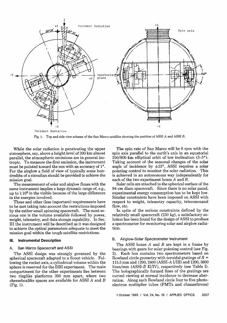
The ASSI boxes A and B are kept in a frame bybearings with gears for solar pointing control (see Fig.2). Each box contains two spectrometers based onRowland circle geometry with toroidal gratings of R =115.5 mm and 1200,2400 (ASSI-A I/III) and 1200,3600lines/mm (ASSI-B II/IV), respectively (see Table I).The holographically formed lines of the gratings arecurved viewing at normal incidence to decrease aber-ration. Along each Rowland circle four to five photo-electron multiplier tubes (PMTs and channeltrons)
1 October 1985 / Vol. 24, No. 19 / APPLIED OPTICS 3207
-y
3
Fig. 2. Views of one ASSI experiment with the light entrances 1 at the two spectrometer planes, the sun sensor 2, the +30 sun pointingmechanism 3, and the mechanical frame structure 4.
keep positions behind corrresponding exit slits, eighteendetectors (channels) in all from the ITT, EMR, andGalileo companies.
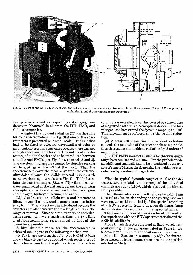
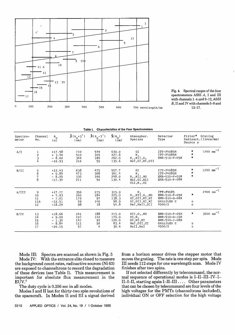
The angle of the incident radiation (27°) is the samefor four spectrometers. In Fig. 3(a) one of the spec-trometers is presented on a small scale. The exit slitshad to be fixed at selected wavelengths of solar oraeronomic interest; in some cases because there was notenough space available for direct mounting of the de-tectors, additional optics had to be introduced betweenexit slits and PMTs [see Fig. 3(b), channels 5 and 6].The wavelength ranges are scanned by stepwise rockingof the gratings within 3' at the most. Then thespectrometers cover the total range from the extremeultraviolet through the visible spectral regions withmany overlapping intervals (see Fig. 4). Table I con-tains the spectral ranges [X(30 ± 30)] with the centerwavelength X(30) at the exit angle o and the emittingatmospheric species, e.g., atomic and molecular oxygenand nitrogen, hydrogen, helium, and ozone.
Light baffles, zero-order light traps, and interferencefilters prevent the individual channels from interferingstray light. This protection was introduced because thedetectors are also sensitive to wavelengths outside therange of interest. Since the radiation to be recordedvaries strongly with wavelength and time, the stray lightlevel from neighboring regions must be kept at thelowest level possible.
A high dynamic range for the spectrometer isachieved making use of the following mechanism:
(i) For longer wavelengths ITT (type F 4085) PMTsallow a bias voltage5 to be applied which repels most ofthe photoelectrons from the photocathode. If a certain
count rate is exceeded, it can be lowered by some ordersof magnitude with this electrooptical device. The biasvoltages used here extend the dynamic range up to 1:103.This mechanism is referred to as the squint reduc-tion.
(ii) A solar cell measuring the incident radiationcontrols the reduction of the entrance slit to a pinhole,thus decreasing the incident radiation by 2 orders ofmagnitude.
(iii) ITT PMTs were not available for the wavelengthrange between 200 and 300 nm. For the pinhole modean additional small slit had to be introduced at the exitslits of some PMTs, again decreasing the incident (solar)radiation by 2 orders of magnitude.
With the typical dynamic range of 1:106 of the de-tectors used, the total dynamic range of the individualchannels goes up to 1:1011, which is not yet the highestratio possible.
The 0.3-mm entrance slit width allows for a 0.7-3-nmspectral resolution, depending on the grating used andwavelength considered. In Fig. 5 the spectral recordingof a EUV spectrum from a gaseous discharge lampdemonstrates the resolution in that spectral range.
There are four modes of operation for ASSI based onthe experience with the EUV spectrometer aboard theAEROS satellites 6 :
Mode I: All detectors are kept at fixed wavelengthpositions, e.g., at the emissions listed in Table I. Bytelecommand, 112 different positions can be chosen.
Mode II: Spectra are scanned by eight (or sixteen,to be chosen by telecommand) steps around the positionselected in Mode I
3208 APPLIED OPTICS / Vol. 24, No. 19 / 1 October 1985
0
0 rC3
0)Q
to
C.)
.
cn:au)
tcc-.C ¢4-
0 > -H C - F
,4 D. C
C), C)U) .,4
H U)
eC 0 u H
rD t0H 0 U 4)
o C) O. 0 O) C C 0 _
C. -H oI C) C) CD 3 Z
C O O '- (\) CC))
C)4 ) 4-.fn
h r. C- H. q C ,) b
O > *,(I C S 44-. C rC J>r C) C-. "-s D v
Sa) 04-E.,
-y o - *)1 . uC-C- C-H C
C)C) CCQCC),C b H
v) -HH-CC) C)-a C C ) -I) S 4C )C
C) *,Z-H 4C D X) rn .) .. CC) ,- 4- C 0 a-C0C00C)
C
1 October 1985 / Vol. 24, No. 19 / APPLIED OPTICS 3209
tn
I 7 7 7 7
0 100 200 300 400 500 600 700 wavelength/nm
Fig. 4. Spectral ranges of the fourspectrometers ASSI A, I and IIIwith channels 1-4 and 9-12, ASSIB, II and IV with channels 5-8 and
13-17.
Table I. Characteristics of the Four Spectrometers
Spectro- Channel B0 I(Bo+3 ) >(z -3 ) >(Bo) Atmospher. Detector Filter* Gratingmeter No. (0) (nm) ?nm) (nm) Species Type Radioact.(lines/mm)
Source o
A/I 1 +17.58 710 549 630.0 0I ITT-F4085M * 1200 mm 12 + 3.40 510 345 427.8 N2 ITT-F4085M *3 - 8.02 344 180 262.0 N2 ,NII,03 EMR-510-F-05M *4 -16.93 216 55 135.6 HeI,OI,HI,OII
B/II 5 +12.43 638 475 557.7 0I ITT-F4085M * 1200 mm 16 + o.89 473 308 391.4 N2 ITT-F4085M *7 - 8.99 330 166 248.0 N2 ,NII,NO EMR-510-F-05M *8 -17.30 211 50 130.4 HeI,OI,HII EMR-510-P-08M
OII,N,,NI
A/III 9 +17.77 356 275 315.9 N2 ITT-F4085 2400 mm 1
10 + 4.93 266 184 225.0 N2 ,NII,02,NO EMR-510-P-05M *11 - 7.01 179 97 138.3 OI,OII,NI,HI EMR-510-G-08M11A -12.51 59 140 98.9 OI,OII,HI,NI GALLILEO C o12 -18.29 98 18 54.8 HeI,HeII,OII 4500/2 o
B/IV 13 +18.66 241 188 215.0 NII,0,,NO EMR-510-P-05M * 3600 mm-14 + 9.09 197 142 170.0 NI,N, EMR-510-G-1OM15 - 1.30 147 92 120.0 OI,NI,HI EMR-510-J-08M16 - 8.84 111 56 83.4 HeI,OII,OI GALLILEO C o17 -20.15 57 4 30.4 HeII,HeI 4500/2 o
Mode III: Spectra are scanned as shown in Fig. 5Mode IV: With the entrance slits closed to measure
the background count rates, radioactive sources (Ni 63)are exposed to channeltrons to record the degradationof these devices (see Table I). This measurement isimportant for absolute flux measurement in theEUV.7
The duty cycle is 0.256 sec in all modes.Modes I and II last for thirty-two spin revolutions of
the spacecraft. In Modes II and III a signal derived
from a horizon sensor drives the stepper motor thatmoves the grating. The rate is one step per spin. ModeIII needs 112 steps for one wavelength scan. Mode IVfinishes after two spins.
If not selected differently by telecommand, the nor-mal sequence of operational modes is I-II-III-IV-I-II-I-II, starting again I-II-IIIl... Other parametersthat can be chosen by telecommand are four levels of thehigh voltages for the PMTs (channeltrons included),individual ON or OFF selection for the high voltage
3210 APPLIED OPTICS / Vol. 24, No. 19 / 1 October 1985
16~~~1
-17~~~~~~~
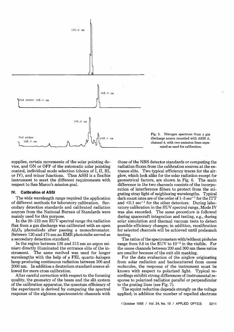
120.0 nm
108.4 nm
order 108.4 nm
120.0 nm
108. 4 nmFig. 5. Nitrogen spectrum from a gasdischarge source recorded with ASSI A,channel 4, with two emission lines sepa-
rated as used for calibration.
supplies, certain movements of the solar pointing de-vice, and ON or OFF of the automatic solar pointingcontrol, individual mode selection (choice of I, II, III,or IV), and minor functions. Thus ASSI is a flexibleinstrument to meet the different requirements withrespect to San Marco's mission goal.
IV. Calibration of ASSI
The wide wavelength range required the applicationof different methods for laboratory calibration. Sec-ondary detection standards and calibrated radiationsources from the National Bureau of Standards weremainly used for this purpose.
In the 20-122-nm EUV spectral range the radiationflux from a gas discharge was calibrated with an openA1203 photodiode after passing a monochromator.Between 120 and 175 nm an EMR phototube served asa secondary detection standard.
In the region between 136 and 313 nm an argon mi-niarc directly illuminated the entrance slits of the in-strument. The same method was used for longerwavelengths with the help of a FEL quartz-halogenlamp producing continuous radiation between 300 and2000 nm. In addition a deuterium standard source al-lowed for more cross calibration.
After careful correction with respect to the focusingquality, the geometry of the beam and the slit systemof the calibration apparatus, the quantum efficiency ofthe experiment is derived by comparing the spectralresponse of the eighteen spectrometric channels with
those of the NBS detector standards or computing theradiation fluxes from the calibration sources at the en-trance slits. Two typical efficiency traces for the air-glow, which look alike for the solar radiation except forgeometrical factors, are shown in Fig. 6. The maindifference in the two channels consists of the incorpo-ration of interference filters to protect from the mi-grating stray light of neighboring wavelengths. Typicaldark count rates are of the order of 1-5 sec 1 for the ITTand <0.1 sec 1 for the other detectors. During labo-ratory calibration in the EUV spectral range, Mode IVwas also recorded. The same procedure is followedduring spacecraft integration and testing, e.g., duringsolar simulation and thermal vacuum tests to detectpossible efficiency changes; in addition, recalibrationfor selected channels will be achieved until prelaunchtesting.
The ratios of the spectrometers with/without pinholesrange from 0.6 in the EUV to 10-2 in the visible. Forthe ozone channels between 200 and 300 nm these ratiosare smaller because of the exit slit masking.
For the data evaluation of the airglow originatingfrom solar radiation and backscattered from ozonemolecules, the response of the instrument must beknown with respect to polarized light. Typical re-cordings exhibit strong differences of instrumental re-sponse to polarized radiation parallel or perpendicularto the grating lines (see Fig. 7).
The squint reduction depends strongly on the voltageapplied; in addition the number of repelled electrons
1 October 1985 / Vol. 24, No. 19 / APPLIED OPTICS 3211
2nd order
( I
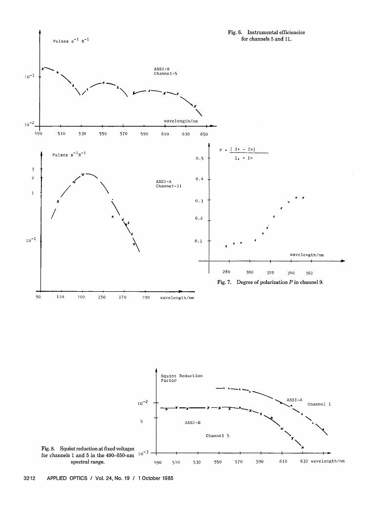
Fig. 6. Instrumental efficienciesfor channels 5 and 11.Pulses s 1 R 1
ASSI-BChannel-5
X~~~~~,-
N
wavelength/nm
490 510 530 550 570 590 610 630 650
0.5 t
p = I I+ - I=1
I+ + I=
0.4 4-
0.3 t
0.2
0. 1x
280 300 320 340 360
Fig. 7. Degree of polarization P in channel 9.
90 110 100 150 170 190 wavelength/nm
-2
Fig. 8. Squint reduction at fixed voltagesfor channels 1 and 5 in the 490-650-nm
spectral range.
Squint ReductionFactor
ASSI-B
490 510 530 550 570 590 610 630 wavelength/nm
3212 APPLIED OPTICS / Vol. 24, No. 19 / 1 October 1985
t0-1 4.
Pulses s 1R 1
3
2
1
7
X
ASSI-AChannel-l
\wavelength/nm
ASSI-AChannel 1
Channel 5
N\y
w I I
*
-- - - -- v 9
10-2
Y If
X
.
- X -- -, Jr-- X-- it
10- 3
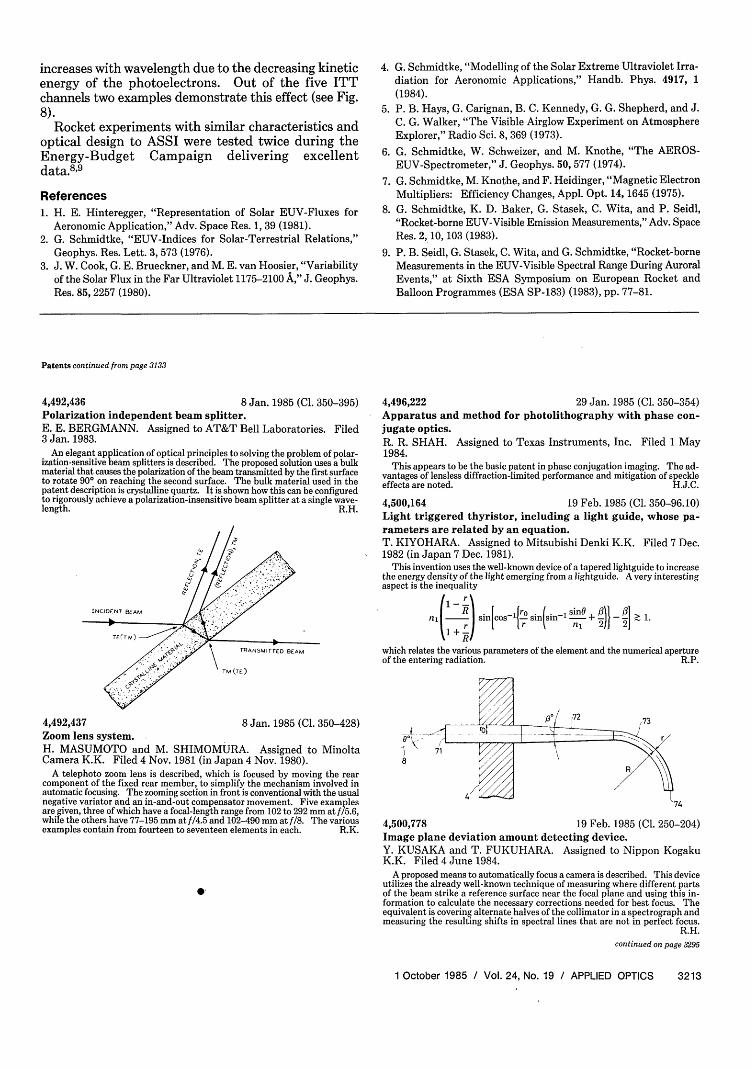
increases with wavelength due to the decreasing kineticenergy of the photoelectrons. Out of the five ITTchannels two examples demonstrate this effect (see Fig.8).
Rocket experiments with similar characteristics andoptical design to ASSI were tested twice during theEnergy-Budget Campaign delivering excellentdata.8 9
References1. H. E. Hinteregger, "Representation of Solar EUV-Fluxes for
Aeronomic Application," Adv. Space Res. 1, 39 (1981).2. G. Schmidtke, "EUV-Indices for Solar-Terrestrial Relations,"
Geophys. Res. Lett. 3, 573 (1976).3. J. W. Cook, G. E. Brueckner, and M. E. van Hoosier, "Variability
of the Solar Flux in the Far Ultraviolet 1175-2100 A," J. Geophys.Res. 85, 2257 (1980).
4. G. Schmidtke, "Modelling of the Solar Extreme Ultraviolet Irra-diation for Aeronomic Applications," Handb. Phys. 4917, 1(1984).
5. P. B. Hays, G. Carignan, B. C. Kennedy, G. G. Shepherd, and J.C. G. Walker, "The Visible Airglow Experiment on AtmosphereExplorer," Radio Sci. 8, 369 (1973).
6. G. Schmidtke, W. Schweizer, and M. Knothe, "The AEROS-EUV-Spectrometer," J. Geophys. 50, 577 (1974).
7. G. Schmidtke, M. Knothe, and F. Heidinger, "Magnetic ElectronMultipliers: Efficiency Changes, Appl. Opt. 14, 1645 (1975).
8. G. Schmidtke, K. D. Baker, G. Stasek, C. Wita, and P. Seidl,"Rocket-borne EUV-Visible Emission Measurements," Adv. SpaceRes. 2, 10, 103 (1983).
9. P. B. Seidl, G. Stasek, C. Wita, and G. Schmidtke, "Rocket-borneMeasurements in the EUV-Visible Spectral Range During AuroralEvents," at Sixth ESA Symposium on European Rocket andBalloon Programmes (ESA SP-183) (1983), pp. 77-81.
Patents continued from page 3133
8 Jan. 1985 (Cl. 350-395)Polarization independent beam splitter.E. E. BERGMANN. Assigned to AT&T Bell Laboratories. Filed3 Jan. 1983.
An elegant application of optical principles to solving the problem of polar-ization-sensitive beam splitters is described. The proposed solution uses a bulkmaterial that causes the polarization of the beam transmitted by the first surfaceto rotate 90° on reaching the second surface. The bulk material used in thepatent description is crystalline quartz. It is shown how this can be configuredto rigorously achieve a polarization-insensitive beam splitter at a single wave-length. R.H.
II
INCIDENT BEAM
TRANSMITTED SEAM
4,496,222 29 Jan. 1985 (Cl. 350-354)Apparatus and method for photolithography with phase con-jugate optics.R. R. SHAH. Assigned to Texas Instruments, Inc. Filed 1 May1984.
This appears to be the basic patent in phase conjugation imaging. The ad-vantages of lensless diffraction-limited performance and mitigation of speckleeffects are noted. H.J.C.
4,500,164 19 Feb. 1985 (Cl. 350-96.10)Light triggered thyristor, including a light guide, whose pa-rameters are related by an equation.T. KIYOHARA. Assigned to Mitsubishi Denki K.K. Filed 7 Dec.1982 (in Japan 7 Dec. 1981).
This invention uses the well-known device of a tapered lightguide to increasethe energy density of the light emerging from a lightguide. A very interestingaspect is the inequality
n1(-)~~-1 snc 1ro sintinl sn + 2}2 n i( 1j) ~ ~ rn, 2 2] 1which relates the various parameters of the element and the numerical apertureof the entering radiation. R.P.
TM (TE)
4,492,437 8 Jan. 1985 (Cl. 350-428)Zoom lens system.H. MASUMOTO and M. SHIMOMURA. Assigned to MinoltaCamera K.K. Filed 4 Nov. 1981 (in Japan 4 Nov. 1980).
A telephoto zoom lens is described, which is focused by moving the rearcomponent of the fixed rear member, to simplify the mechanism involved inautomatic focusing. The zooming section in front is conventional with the usualnegative variator and an in-and-out compensator movement. Five examplesare given, three of which have a focal-length range from 102 to 292 mm at f/5.6,while the others have 77-195 mm at f/4.5 and 102-490 mm at f/8. The variousexamples contain from fourteen to seventeen elements in each. R.K.
.
4,500,778
'74
19 Feb. 1985 (Cl. 250-204)Image plane deviation amount detecting device.Y. KUSAKA and T. FUKUHARA. Assigned to Nippon KogakuK.K. Filed 4 June 1984.
A proposed means to automatically focus a camera is described. This deviceutilizes the already well-known technique of measuring where different partsof the beam strike a reference surface near the focal plane and using this in-formation to calculate the necessary corrections needed for best focus. Theequivalent is covering alternate halves of the collimator in a spectrograph andmeasuring the resulting shifts in spectral lines that are not in perfect focus.
R.H.continued on page 3295
1 October 1985 / Vol. 24, No. 19 / APPLIED OPTICS 3213
4,492,436