airborne wifi networ ks through directional antenna .../67531/metadc799469/m2/1/high... · airborne...
TRANSCRIPT
AIRBORNE WIFI NETWORKS THROUGH DIRECTIONAL ANTENNA:
AN EXPERIMENTAL STUDY
Yixin Gu
Thesis Prepared for the Degree of
MASTER OF SCIENCE
UNIVERSITY OF NORTH TEXAS
May 2015
APPROVED:
Shengli Fu, Major Professor and Chair of the Department of Electrical Engineering
Yan Wan, Committee Member Hualiang Zhang, Committee Member Hyoung Soo Kim, Committee Member Costas Tsatsoulis, Dean of the College of
Engineering and Interim Dean of the Toulouse Graduate School
Gu, Yixin. Airborne WiFi Networks through Directional Antenna: An Experimental
Study. Master of Science (Electrical Engineering), May 2015, 50 pp., 3 tables, 46 figures,
26 numbered references.
In situations where information infrastructure is destroyed or not available, on-
demand information infrastructure is pivotal for the success of rescue missions. In this
paper, a drone-carried on demand information infrastructure for long-distance WiFi
transmission system is developed. It can be used in the areas including emergency
response, public event, and battlefield. The WiFi network can be connected to the Internet
to extend WiFi access to areas where WiFi and other Internet infrastructures are not
available.
In order to establish a local area network to propagate WIFI service, directional
antennas and wireless routers are used to create it. Due to unstable working condition on
the flying drones, a precise heading turning stage is designed to maintain the two
directional antennas facing to each other. Even if external interferences change the
heading of the drones, the stages will automatically rotate back to where it should be to
offset the bias. Also, to maintain the same flying altitude, a ground controller is designed
to measure the height of the drones so that the directional antennas can communicate to
each other successfully. To verify the design of the whole system, quite a few field
experiments were performed. Experiments results indicates the design is reliable, viable
and successful. Especially at disaster areas, it’ll help people a lot.

Copyright 2015
By
Yixin Gu
ii

iii
ACKNOWLEDGEMENTS
I would like to express the deepest appreciation to my major professor Dr. Shengli
Fu, who has the attitude and the substance of a genius: he continually and convincingly
conveyed a spirit of adventure in regard to knowledge and research, and an excitement
in regard to teaching. His expertise in wireless communication and sensor network region
improved my research skills and prepared me for future challenges. Without Dr. Fu’s
guidance and persistent help, this thesis would not have been possible.
I would like to thank my thesis committee members, Professor Yan Wan and
Professor Hualiang Zhang for their helpful suggestions and comments during my study.
I want to thank all of my lab mates for their help, support, and cooperation. Finally,
I want to express thanks to my family’s constant source of inspiration and support.
TABLE OF CONTENTS
Page
ACKNOWLEDGEMENTS ............................................................................................... iii LIST OF TABLES ............................................................................................................ vi LIST OF FIGURES ......................................................................................................... vii CHAPTER 1 INTRODUCTION ........................................................................................ 1 CHAPTER 2 DRONE SYSTEM ...................................................................................... 3
2.1 DJI F550 Hexacopter ................................................................................. 5
2.1.1 Flight Controller: DJI Self-Controller ................................................ 6
2.1.2 FUTABA Remote Controller ............................................................ 7
2.1.3 UBIQUITI NANO Station Directional Antenna ................................. 9
2.2 TENDA A6 Wireless Router ..................................................................... 11
2.3 ARDUINO and XBEE ............................................................................... 12 CHAPTER 3 COMMUNICATION SYSTEM ................................................................... 15
3.1 Overall Communication Network Topology .............................................. 15
3.2 NANO Station Antenna ............................................................................ 17
3.3 TENDA A6 Wireless Router ..................................................................... 19
3.4 Power Supply ........................................................................................... 21 CHAPTER 4 HEADING CONTROL SYSTEM ............................................................... 24
4.1 Directional Antenna Heading System ...................................................... 24
4.2 Ground Controller .................................................................................... 30
4.3 UAVs’ Modification ................................................................................... 32 CHAPTER 5 FIELD TEST ............................................................................................. 34
5.1 UBIQUITI AIRVIEW2 Spectrum Analyzer ................................................ 34
5.2 JPERF Bandwidth Tool ............................................................................ 37
5.3 Real Time Video Test ............................................................................... 39
iv
5.4 Field Measurement .................................................................................. 40
5.4.1 Experiment with Ldd=150m ........................................................... 43
5.4.2 Experiment with Ldd=300m ........................................................... 44
5.4.3 Experiment with Ldd=1Km ............................................................ 45 CHAPTER 6 CONCLUSION AND FUTURE WORK ..................................................... 47 REFERENCES .............................................................................................................. 49
v
LIST OF TABLES
Page
Table 3.1 Current Consumption ..................................................................................... 22
Table 3.2 12V Power Consumption ............................................................................... 22
Table 6.1 Throughput Summary: (Unit: Mbps) ............................................................... 49
vi
LIST OF FIGURES
Page
2.1 Drones' System Model .............................................................................................. 3
2.2 Antenna Structure ...................................................................................................... 4
2.3 DJI F550 Hexacopter ................................................................................................ 5
2.4 DJI NAZA-M Lite Self-Controller ................................................................................ 6
2.5 Daylight Flying ........................................................................................................... 7
2.6 Nocturnal Flying ........................................................................................................ 7
2.7 FUTABA T9CAP 72MHz Remote Controller .............................................................. 7
2.8 NANO Station Antenna .............................................................................................. 9
2.9 Patch Antenna Structure ........................................................................................... 9
2.10 Radiation Pattern ................................................................................................... 10
2.11 TENDA A6 Wireless Router ................................................................................... 11
2.12 ARDUINO .............................................................................................................. 12
2.13 Atmega328P Chip ................................................................................................. 12
2.14 DIJI XBEE 2.4G Wireless Module ......................................................................... 13
2.15 X-CTU ................................................................................................................... 13
2.16 XBEE 2.4G Channels ............................................................................................ 13
2.17 WIFI Channels....................................................................................................... 14
3.1 Network Topology .................................................................................................... 15
3.2 Network Topology with IP Addresses ...................................................................... 16
3.3 Configuration of AP Mode ....................................................................................... 17
3.4 Status of NANO Station in STATION Mode ............................................................. 18
vii
3.5 Configuration of TENDA A6 ..................................................................................... 19
3.6 Configuration of REPEATER Mode ......................................................................... 20
3.7 LM2596 DC-DC Step-Down Power Supply Board................................................... 21
3.8 Circuit of LM2596 .................................................................................................... 22
4.1 LSM303 E-Compass ............................................................................................... 24
4.2 Design of Antenna Plate .......................................................................................... 24
4.3 Geared Motor: Sanyo NA4S .................................................................................... 25
4.4 Design of Ground Controller .................................................................................... 29
4.5 Modification of UAV Structure .................................................................................. 33
5.1 UBIQUITI AIRVIEW2 Spectrum Analyzer ................................................................ 35
5.2 Interface of Airview2 ................................................................................................ 36
5.3 TENDA A6 Shift Channel to 9 .................................................................................. 37
5.4 Nana Station Shift Channel to 11 ............................................................................ 37
5.5 JPERF’s Measurement ........................................................................................... 38
5.6 JPERF Screenshot .................................................................................................. 39
5.7 YAWCAM Real-Time Video Test Screenshot ........................................................... 40
5.8 Client side Screenshot ............................................................................................ 41
5.9 UAVs in Field Test ................................................................................................... 42
5.10 Fresnel Zone ......................................................................................................... 43
5.11 Ldd=150 on Playground of UNT Discovery Park ................................................... 45
5.12 Ldd=150 Static/Hovering Data .............................................................................. 45
5.13 Ldd=300 on Playground of UNT Discovery Park ................................................... 46
5.14 Ldd=300 Static/Hovering Data .............................................................................. 47
viii
5.15 Ldd=1Km in a Ranch in Mckinney TX ................................................................... 48
5.16 Ldd=1Km Static/Hovering Data ............................................................................. 49
ix
CHAPTER 1
INTRODUCTION
At present, more and more people are concerning communication in emergency
disaster areas. In disaster areas which damaged by earthquake, flooding or avalanche,
basic infrastructures like power plants, cellphone base stations and so forth are often out
of orders or even damaged as well. In such cases, it’s quite helpful if there’s a temporary
WIFI (Wireless Fidelity) connection from safe areas to such disaster areas [1]-[4]. The co-
operation between rescue teams like rescue dogs and rescue robots with control centers
will greatly benefit from it. Also, the refugees in such areas can connect with their friends
and families by their own smart phones, tablets and laptops as soon as possible to let
them know their situation and requirements.
In these years, unmanned aerial vehicles (UAV) technique has been greatly
developed [6][7]. The characteristics of UAVs including controllability, high moving speed,
self-navigation and all kinds of fail-safe protections make them to be a promising
communication solution. Although right now there’re still some considerations on flight
time, payload, dynamic communication performance and so on [2],[6]-[8], it’s undoubtable
that the UAV WIFI is a fast response internet service provider. In the paper, the feasibility
of establishing a WIFI connection by using UAVs and WIFI equipment will be studied to
provide internet service to disaster areas.
Considering the cost, compatibility and regulation, the commercial IEEE802.11
WIFI is quite suitable for our drones [10],[11]. People have conducted lots of experiments
1
to test their throughput and packet loss by using omni-directional antennas. For example,
people tested video transmission between two fixed-wing planes to estimate the feasibility
of 802.11n [2]. Their experiments show that the lower throughput and package
transmitting rate than theory are a significant challenge for high-mobility airborne wireless
transmission. Due to short transmission range of 802.11(I.E 100 meters) transmit by omni-
directional antennas, directional antennas will be exploited to communicate between
drones to increase transmission range and cover range. So far, most experiments are
between ground station and drone, obtaining signal by tracking antenna on the ground,
or between high speed fixed-wing and fixed-wing[15],[16]. It’s a new attempt to establish
WIFI connection between two relatively stable drones in our experiment.
2
CHAPTER 2
DRONE SYSTEM
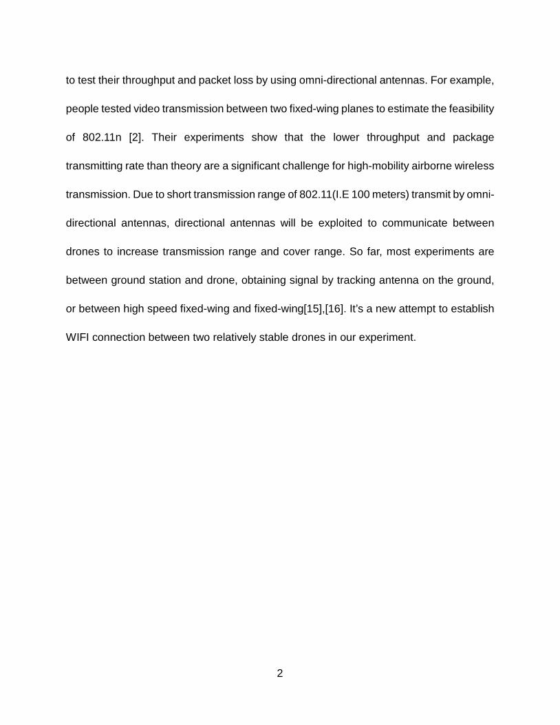
Fig. 2.1. Drones’ system model
Our system is consisted by two identical drones as shown in Fig. 2.1. Each one
carries one NANO station antenna for long distance communication to each other, one
TENDA A6 for connecting laptops on the ground with NANO station antenna and one
ARDUINO atmega328P MCU with barometer and e-compass sensors as shown in Fig.
2.2. For the disaster areas, one drone will be placed at safe area with internet connection
and fly the other one directly into the disaster area. After the drone arrives the disaster
area, it’ll stay in the sky at fixed height for certain period to broadcast WIF (Wireless
Fidelity) service to people on the ground. Before batteries die, the drone will fly back to
safe area for battery replacement and fly to the disaster area repeatedly. In the
experiments, the both drones will fly to same height with different distance to test their
communication performance.
3
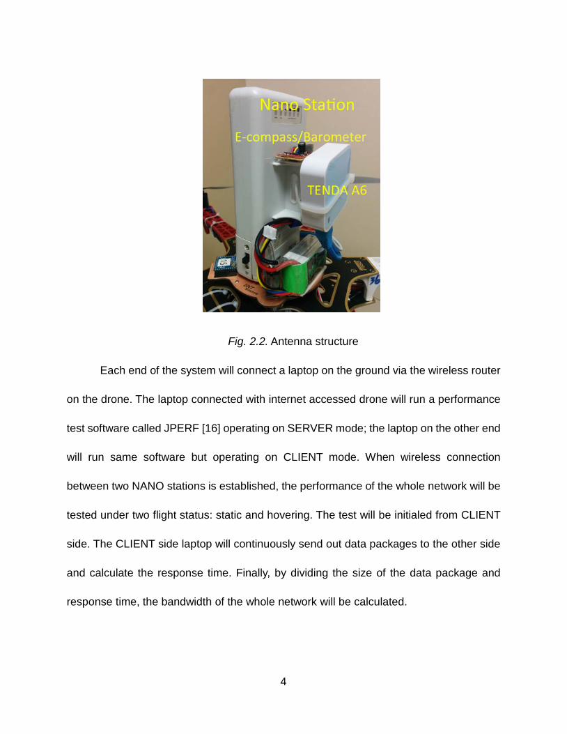
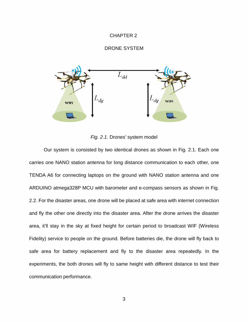
Fig. 2.2. Antenna structure
Each end of the system will connect a laptop on the ground via the wireless router
on the drone. The laptop connected with internet accessed drone will run a performance
test software called JPERF [16] operating on SERVER mode; the laptop on the other end
will run same software but operating on CLIENT mode. When wireless connection
between two NANO stations is established, the performance of the whole network will be
tested under two flight status: static and hovering. The test will be initialed from CLIENT
side. The CLIENT side laptop will continuously send out data packages to the other side
and calculate the response time. Finally, by dividing the size of the data package and
response time, the bandwidth of the whole network will be calculated.
4
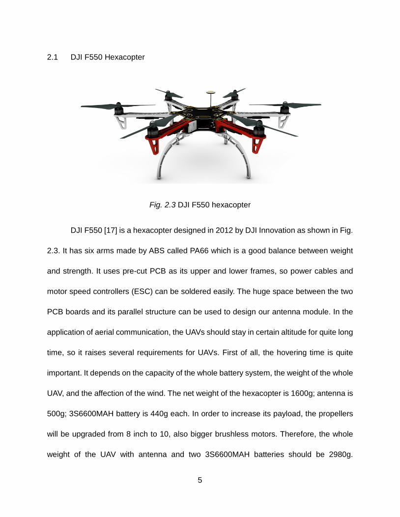
2.1 DJI F550 Hexacopter
Fig. 2.3 DJI F550 hexacopter
DJI F550 [17] is a hexacopter designed in 2012 by DJI Innovation as shown in Fig.
2.3. It has six arms made by ABS called PA66 which is a good balance between weight
and strength. It uses pre-cut PCB as its upper and lower frames, so power cables and
motor speed controllers (ESC) can be soldered easily. The huge space between the two
PCB boards and its parallel structure can be used to design our antenna module. In the
application of aerial communication, the UAVs should stay in certain altitude for quite long
time, so it raises several requirements for UAVs. First of all, the hovering time is quite
important. It depends on the capacity of the whole battery system, the weight of the whole
UAV, and the affection of the wind. The net weight of the hexacopter is 1600g; antenna is
500g; 3S6600MAH battery is 440g each. In order to increase its payload, the propellers
will be upgraded from 8 inch to 10, also bigger brushless motors. Therefore, the whole
weight of the UAV with antenna and two 3S6600MAH batteries should be 2980g.
5
Obviously, at present the Li-ion polymer battery is the best choice. Although right now the
weight of our two 3S6600MAH batteries is around 880g, it provides nearly 22 minutes’
hovering time.
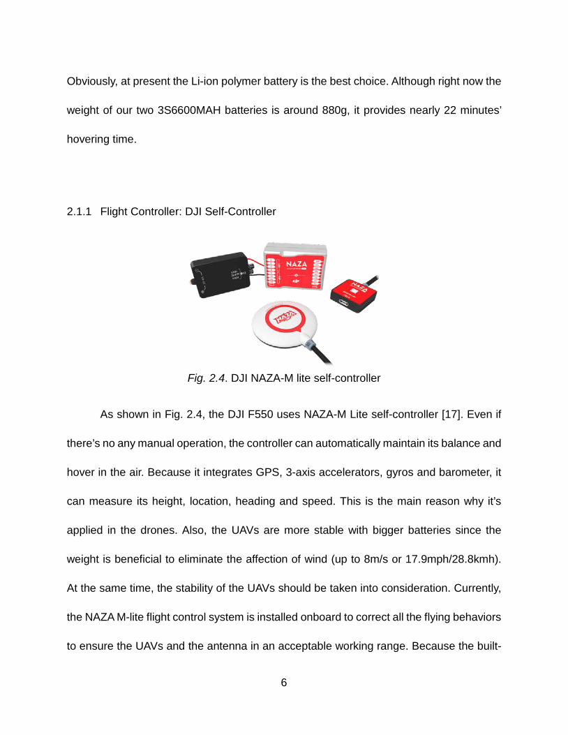
2.1.1 Flight Controller: DJI Self-Controller
Fig. 2.4. DJI NAZA-M lite self-controller
As shown in Fig. 2.4, the DJI F550 uses NAZA-M Lite self-controller [17]. Even if
there’s no any manual operation, the controller can automatically maintain its balance and
hover in the air. Because it integrates GPS, 3-axis accelerators, gyros and barometer, it
can measure its height, location, heading and speed. This is the main reason why it’s
applied in the drones. Also, the UAVs are more stable with bigger batteries since the
weight is beneficial to eliminate the affection of wind (up to 8m/s or 17.9mph/28.8kmh).
At the same time, the stability of the UAVs should be taken into consideration. Currently,
the NAZA M-lite flight control system is installed onboard to correct all the flying behaviors
to ensure the UAVs and the antenna in an acceptable working range. Because the built-
6
in GPS, accelerators and gyros, the flight control system can guarantee the UAVs stay at
a fixed point without big drifting; at least it won’t be blown away. Based on the onboard
GPS navigation, the UAVs can automatically return and land after operation. Therefore,
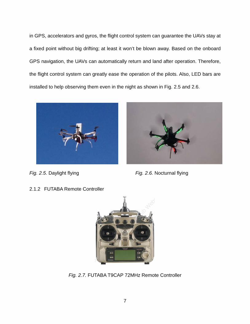
the flight control system can greatly ease the operation of the pilots. Also, LED bars are
installed to help observing them even in the night as shown in Fig. 2.5 and 2.6.
Fig. 2.5. Daylight flying Fig. 2.6. Nocturnal flying
2.1.2 FUTABA Remote Controller
Fig. 2.7. FUTABA T9CAP 72MHz Remote Controller
7
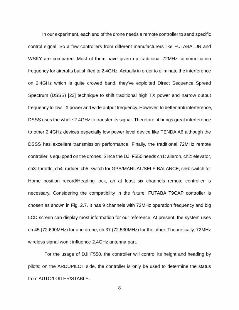
In our experiment, each end of the drone needs a remote controller to send specific
control signal. So a few controllers from different manufacturers like FUTABA, JR and
WSKY are compared. Most of them have given up traditional 72MHz communication
frequency for aircrafts but shifted to 2.4GHz. Actually in order to eliminate the interference
on 2.4GHz which is quite crowed band, they’ve exploited Direct Sequence Spread
Spectrum (DSSS) [22] technique to shift traditional high TX power and narrow output
frequency to low TX power and wide output frequency. However, to better anti interference,
DSSS uses the whole 2.4GHz to transfer its signal. Therefore, it brings great interference
to other 2.4GHz devices especially low power level device like TENDA A6 although the
DSSS has excellent transmission performance. Finally, the traditional 72MHz remote
controller is equipped on the drones. Since the DJI F550 needs ch1: aileron, ch2: elevator,
ch3: throttle, ch4: rudder, ch5: switch for GPS/MANUAL/SELF-BALANCE, ch6: switch for
Home position record/Heading lock, an at least six channels remote controller is
necessary. Considering the compatibility in the future, FUTABA T9CAP controller is
chosen as shown in Fig. 2.7. It has 9 channels with 72MHz operation frequency and big
LCD screen can display most information for our reference. At present, the system uses
ch:45 (72.690MHz) for one drone, ch:37 (72.530MHz) for the other. Theoretically, 72MHz
wireless signal won’t influence 2.4GHz antenna part.
For the usage of DJI F550, the controller will control its height and heading by
pilots; on the ARDUPILOT side, the controller is only be used to determine the status
from AUTO/LOITER/STABLE.
8
2.1.3 UBIQUITI NANO Station Directional Antenna
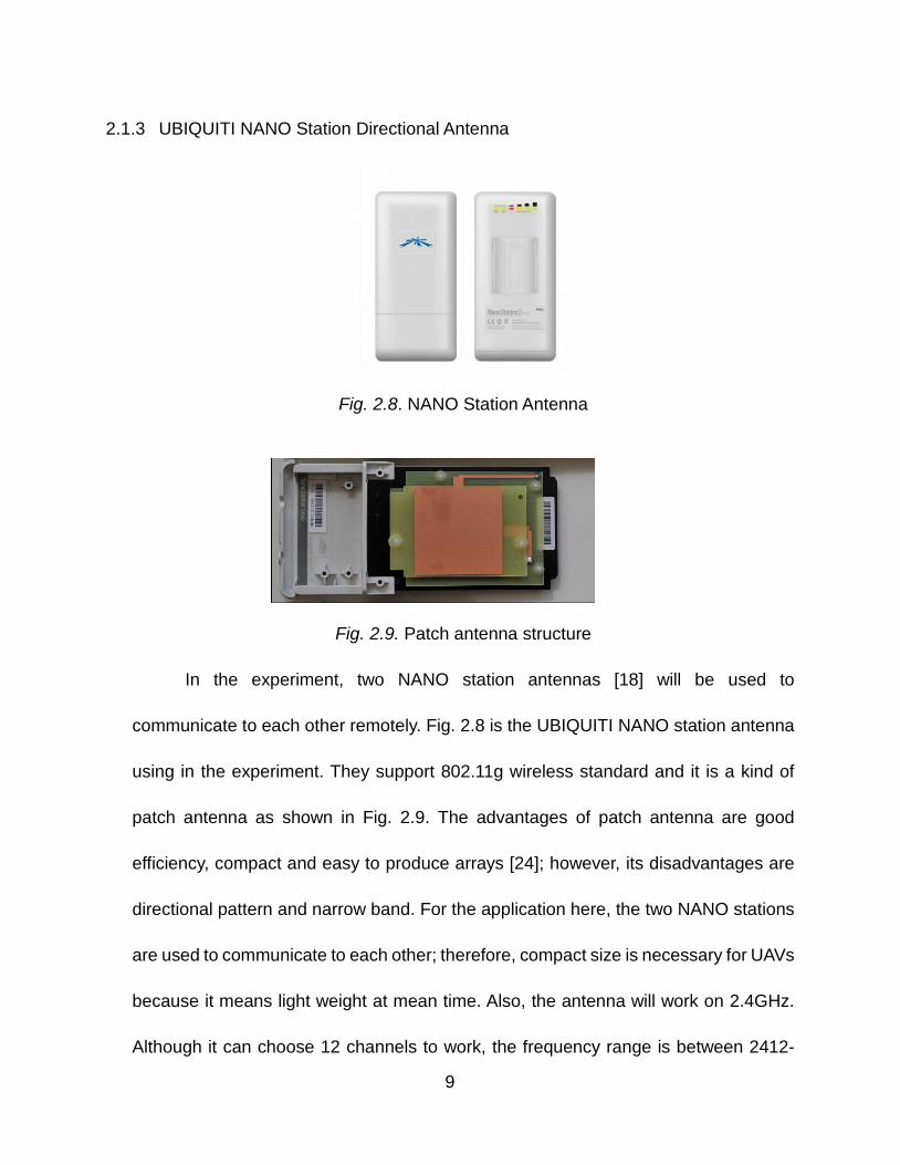
Fig. 2.8. NANO Station Antenna
Fig. 2.9. Patch antenna structure
In the experiment, two NANO station antennas [18] will be used to
communicate to each other remotely. Fig. 2.8 is the UBIQUITI NANO station antenna
using in the experiment. They support 802.11g wireless standard and it is a kind of
patch antenna as shown in Fig. 2.9. The advantages of patch antenna are good
efficiency, compact and easy to produce arrays [24]; however, its disadvantages are
directional pattern and narrow band. For the application here, the two NANO stations
are used to communicate to each other; therefore, compact size is necessary for UAVs
because it means light weight at mean time. Also, the antenna will work on 2.4GHz.
Although it can choose 12 channels to work, the frequency range is between 2412-
9
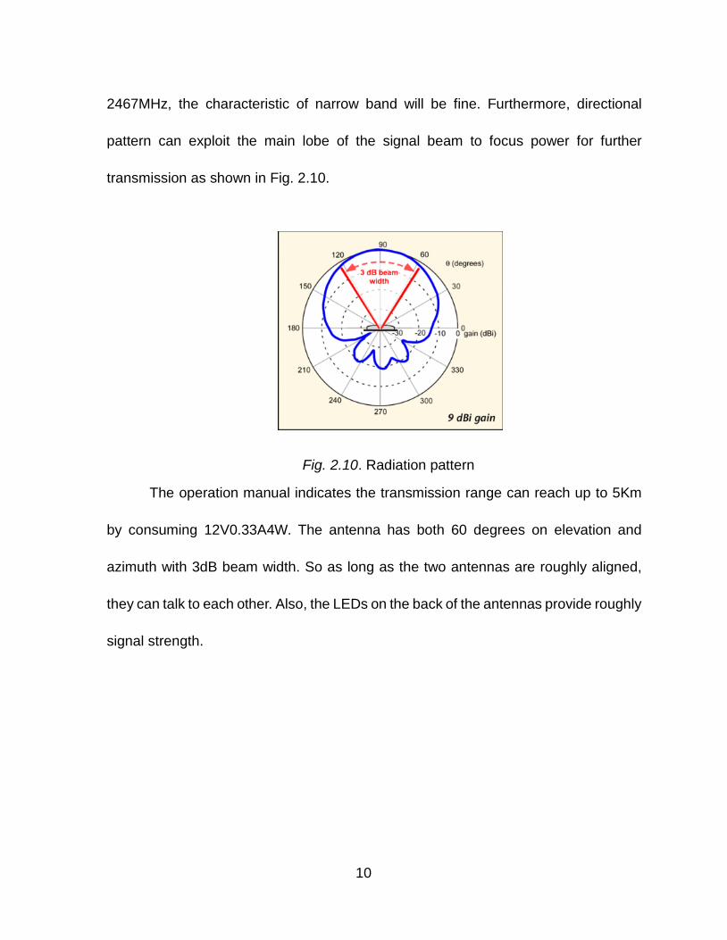
2467MHz, the characteristic of narrow band will be fine. Furthermore, directional
pattern can exploit the main lobe of the signal beam to focus power for further
transmission as shown in Fig. 2.10.
Fig. 2.10. Radiation pattern
The operation manual indicates the transmission range can reach up to 5Km
by consuming 12V0.33A4W. The antenna has both 60 degrees on elevation and
azimuth with 3dB beam width. So as long as the two antennas are roughly aligned,
they can talk to each other. Also, the LEDs on the back of the antennas provide roughly
signal strength.
10
2.2 TENDA A6 Wireless Router
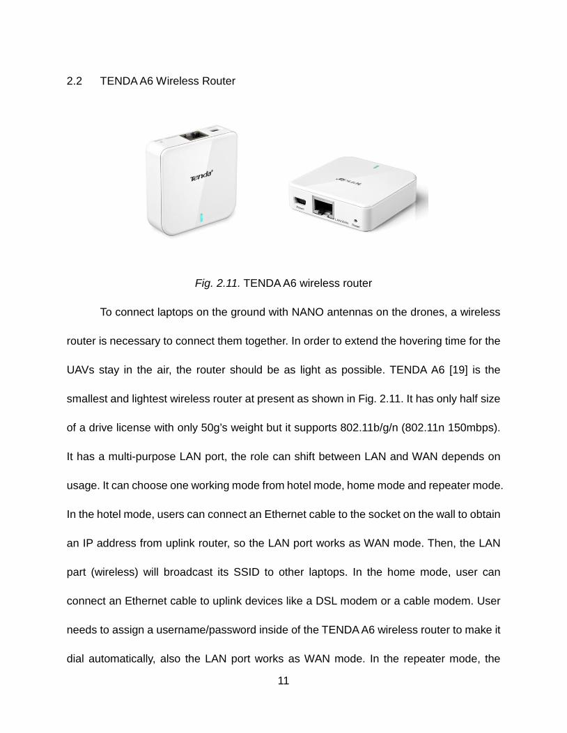
Fig. 2.11. TENDA A6 wireless router
To connect laptops on the ground with NANO antennas on the drones, a wireless
router is necessary to connect them together. In order to extend the hovering time for the
UAVs stay in the air, the router should be as light as possible. TENDA A6 [19] is the
smallest and lightest wireless router at present as shown in Fig. 2.11. It has only half size
of a drive license with only 50g’s weight but it supports 802.11b/g/n (802.11n 150mbps).
It has a multi-purpose LAN port, the role can shift between LAN and WAN depends on
usage. It can choose one working mode from hotel mode, home mode and repeater mode.
In the hotel mode, users can connect an Ethernet cable to the socket on the wall to obtain
an IP address from uplink router, so the LAN port works as WAN mode. Then, the LAN
part (wireless) will broadcast its SSID to other laptops. In the home mode, user can
connect an Ethernet cable to uplink devices like a DSL modem or a cable modem. User
needs to assign a username/password inside of the TENDA A6 wireless router to make it
dial automatically, also the LAN port works as WAN mode. In the repeater mode, the
11
TENDA A6 wireless router can be set to hook on another wireless device and transfer its
internet service to A6’s own connected laptops. Here, the LAN port works as LAN mode,
user can connect a laptop by Ethernet cable or wireless to use internet. Here, the repeater
mode is chosen to make the Ethernet as LAN to connect wireless part (also LAN).
2.3 ARDUINO and XBEE
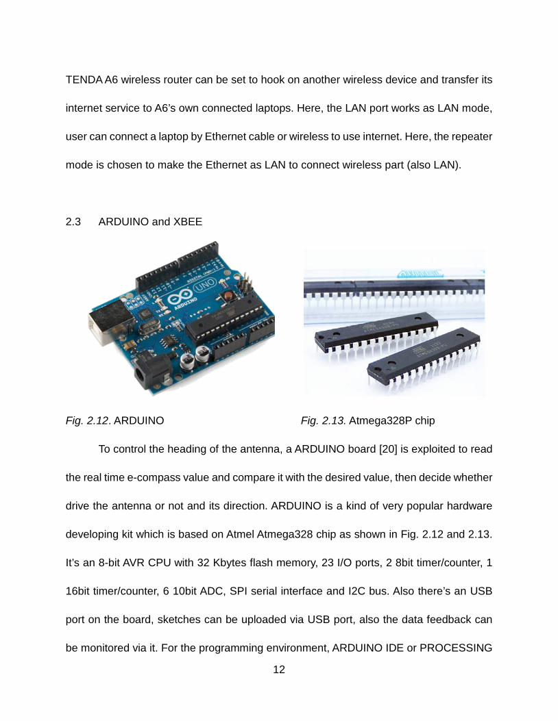
Fig. 2.12. ARDUINO Fig. 2.13. Atmega328P chip
To control the heading of the antenna, a ARDUINO board [20] is exploited to read
the real time e-compass value and compare it with the desired value, then decide whether
drive the antenna or not and its direction. ARDUINO is a kind of very popular hardware
developing kit which is based on Atmel Atmega328 chip as shown in Fig. 2.12 and 2.13.
It’s an 8-bit AVR CPU with 32 Kbytes flash memory, 23 I/O ports, 2 8bit timer/counter, 1
16bit timer/counter, 6 10bit ADC, SPI serial interface and I2C bus. Also there’s an USB
port on the board, sketches can be uploaded via USB port, also the data feedback can
be monitored via it. For the programming environment, ARDUINO IDE or PROCESSING
12
can be used here, both are quite easy to understand. It’s not necessary to spend lots of
time, then data can be captured from sensors and drive peripheral devices like LED,
speakers and motors.
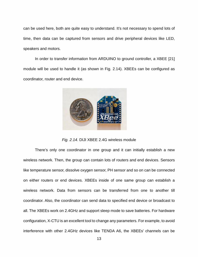
In order to transfer information from ARDUINO to ground controller, a XBEE [21]
module will be used to handle it (as shown in Fig. 2.14). XBEEs can be configured as
coordinator, router and end device.
Fig. 2.14. DIJI XBEE 2.4G wireless module
There’s only one coordinator in one group and it can initially establish a new
wireless network. Then, the group can contain lots of routers and end devices. Sensors
like temperature sensor, dissolve oxygen sensor, PH sensor and so on can be connected
on either routers or end devices. XBEEs inside of one same group can establish a
wireless network. Data from sensors can be transferred from one to another till
coordinator. Also, the coordinator can send data to specified end device or broadcast to
all. The XBEEs work on 2.4GHz and support sleep mode to save batteries. For hardware
configuration, X-CTU is an excellent tool to change any parameters. For example, to avoid
interference with other 2.4GHz devices like TENDA A6, the XBEEs’ channels can be
13
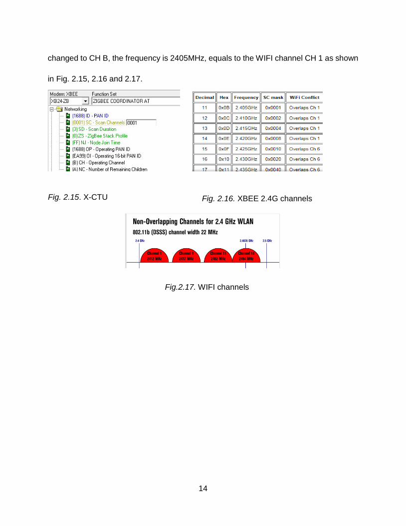
changed to CH B, the frequency is 2405MHz, equals to the WIFI channel CH 1 as shown
in Fig. 2.15, 2.16 and 2.17.
Fig. 2.15. X-CTU Fig. 2.16. XBEE 2.4G channels
Fig.2.17. WIFI channels
14
CHAPTER 3
COMMUNICATION SYSTEM
3.1 Overall Communication Network Topology
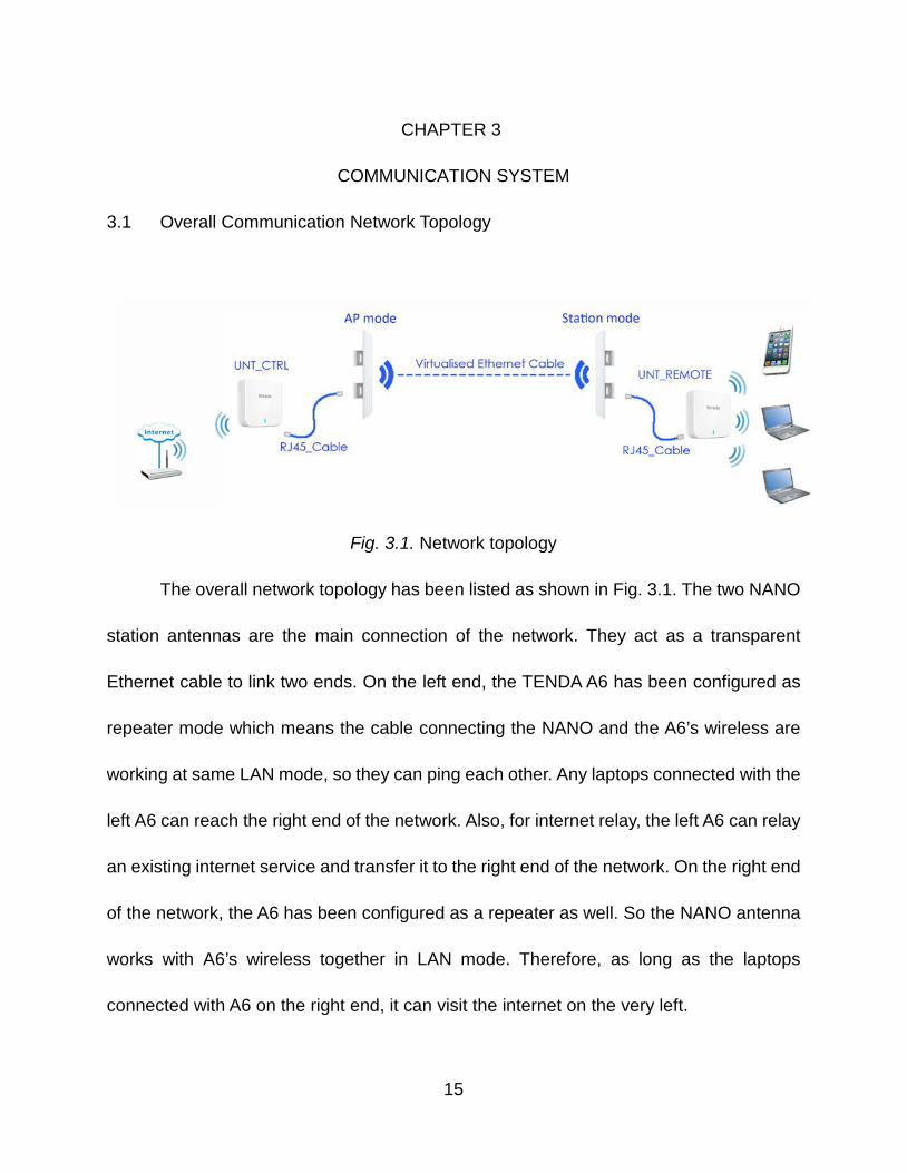
Fig. 3.1. Network topology
The overall network topology has been listed as shown in Fig. 3.1. The two NANO
station antennas are the main connection of the network. They act as a transparent
Ethernet cable to link two ends. On the left end, the TENDA A6 has been configured as
repeater mode which means the cable connecting the NANO and the A6’s wireless are
working at same LAN mode, so they can ping each other. Any laptops connected with the
left A6 can reach the right end of the network. Also, for internet relay, the left A6 can relay
an existing internet service and transfer it to the right end of the network. On the right end
of the network, the A6 has been configured as a repeater as well. So the NANO antenna
works with A6’s wireless together in LAN mode. Therefore, as long as the laptops
connected with A6 on the right end, it can visit the internet on the very left.
15
Any laptop on UNT_REMOTE side can ping all the four devices successfully
except the internet source (WAN side of internet, LAN can be reached though) because
of different network segment. In order to test the whole network performance, all the four
configuration interface pages should be logged in simultaneously to check and modify.
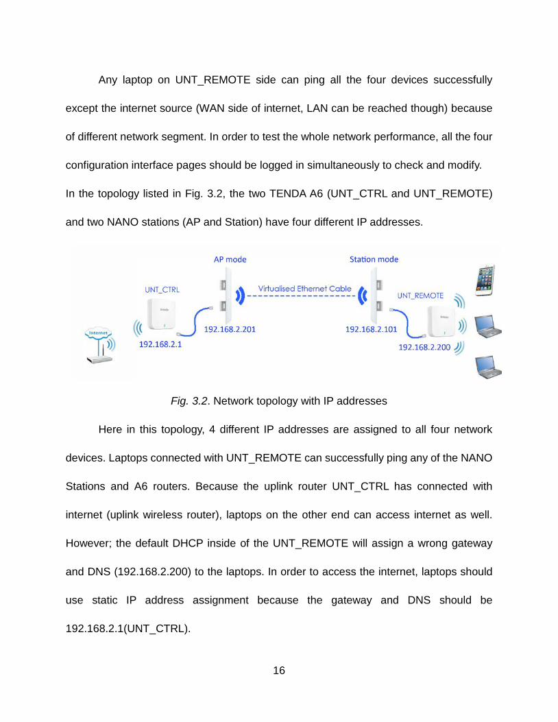
In the topology listed in Fig. 3.2, the two TENDA A6 (UNT_CTRL and UNT_REMOTE)
and two NANO stations (AP and Station) have four different IP addresses.
Fig. 3.2. Network topology with IP addresses
Here in this topology, 4 different IP addresses are assigned to all four network
devices. Laptops connected with UNT_REMOTE can successfully ping any of the NANO
Stations and A6 routers. Because the uplink router UNT_CTRL has connected with
internet (uplink wireless router), laptops on the other end can access internet as well.
However; the default DHCP inside of the UNT_REMOTE will assign a wrong gateway
and DNS (192.168.2.200) to the laptops. In order to access the internet, laptops should
use static IP address assignment because the gateway and DNS should be
192.168.2.1(UNT_CTRL).
16
3.2 NANO Station Antenna
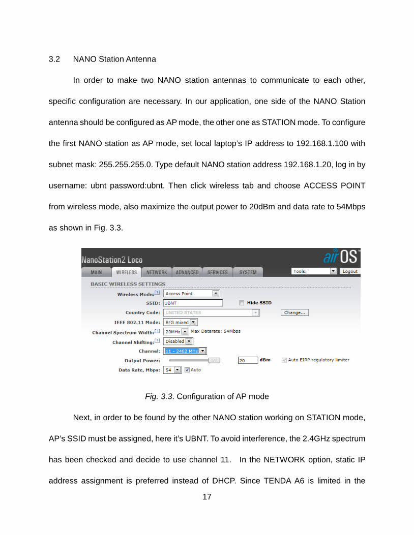
In order to make two NANO station antennas to communicate to each other,
specific configuration are necessary. In our application, one side of the NANO Station
antenna should be configured as AP mode, the other one as STATION mode. To configure
the first NANO station as AP mode, set local laptop’s IP address to 192.168.1.100 with
subnet mask: 255.255.255.0. Type default NANO station address 192.168.1.20, log in by
username: ubnt password:ubnt. Then click wireless tab and choose ACCESS POINT
from wireless mode, also maximize the output power to 20dBm and data rate to 54Mbps
as shown in Fig. 3.3.
Fig. 3.3. Configuration of AP mode
Next, in order to be found by the other NANO station working on STATION mode,
AP’s SSID must be assigned, here it’s UBNT. To avoid interference, the 2.4GHz spectrum
has been checked and decide to use channel 11. In the NETWORK option, static IP
address assignment is preferred instead of DHCP. Since TENDA A6 is limited in the
17
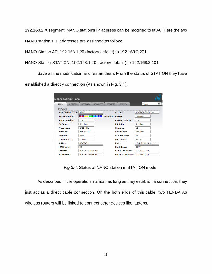
192.168.2.X segment, NANO station’s IP address can be modified to fit A6. Here the two
NANO station’s IP addresses are assigned as follow:
NANO Station AP: 192.168.1.20 (factory default) to 192.168.2.201
NANO Station STATION: 192.168.1.20 (factory default) to 192.168.2.101
Save all the modification and restart them. From the status of STATION they have
established a directly connection (As shown in Fig. 3.4).
As described in the operation manual, as long as they establish a connection, they
just act as a direct cable connection. On the both ends of this cable, two TENDA A6
wireless routers will be linked to connect other devices like laptops.
Fig.3.4. Status of NANO station in STATION mode
18
3.3 TENDA A6 Wireless Router
Fig. 3.5. Configuration of TENDA A6
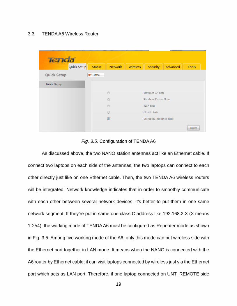
As discussed above, the two NANO station antennas act like an Ethernet cable. If
connect two laptops on each side of the antennas, the two laptops can connect to each
other directly just like on one Ethernet cable. Then, the two TENDA A6 wireless routers
will be integrated. Network knowledge indicates that in order to smoothly communicate
with each other between several network devices, it’s better to put them in one same
network segment. If they’re put in same one class C address like 192.168.2.X (X means
1-254), the working mode of TENDA A6 must be configured as Repeater mode as shown
in Fig. 3.5. Among five working mode of the A6, only this mode can put wireless side with
the Ethernet port together in LAN mode. It means when the NANO is connected with the
A6 router by Ethernet cable; it can visit laptops connected by wireless just via the Ethernet
port which acts as LAN port. Therefore, if one laptop connected on UNT_REMOTE side
19
gives a PING command to the other laptop connected on the UNT_CTRL side, it will
receive the response successfully.
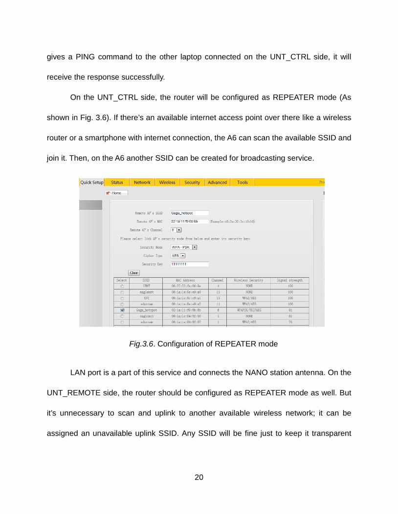
On the UNT_CTRL side, the router will be configured as REPEATER mode (As
shown in Fig. 3.6). If there’s an available internet access point over there like a wireless
router or a smartphone with internet connection, the A6 can scan the available SSID and
join it. Then, on the A6 another SSID can be created for broadcasting service.
LAN port is a part of this service and connects the NANO station antenna. On the
UNT_REMOTE side, the router should be configured as REPEATER mode as well. But
it’s unnecessary to scan and uplink to another available wireless network; it can be
assigned an unavailable uplink SSID. Any SSID will be fine just to keep it transparent
Fig.3.6. Configuration of REPEATER mode
20
between wireless and LAN port. Also, its output SSID can be connected by other laptops,
tablets and smartphones.
3.4 Power Supply
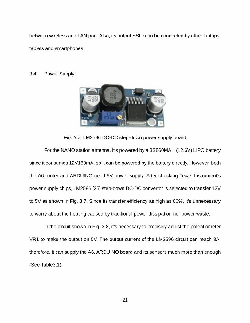
Fig. 3.7. LM2596 DC-DC step-down power supply board
For the NANO station antenna, it’s powered by a 3S860MAH (12.6V) LIPO battery
since it consumes 12V180mA, so it can be powered by the battery directly. However, both
the A6 router and ARDUINO need 5V power supply. After checking Texas Instrument’s
power supply chips, LM2596 [25] step-down DC-DC convertor is selected to transfer 12V
to 5V as shown in Fig. 3.7. Since its transfer efficiency as high as 80%, it’s unnecessary
to worry about the heating caused by traditional power dissipation nor power waste.
In the circuit shown in Fig. 3.8, it’s necessary to precisely adjust the potentiometer
VR1 to make the output on 5V. The output current of the LM2596 circuit can reach 3A;
therefore, it can supply the A6, ARDUINO board and its sensors much more than enough
(See Table3.1).
21
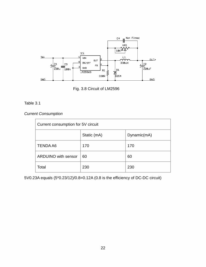
Table 3.1
Current Consumption
Current consumption for 5V circuit
Static (mA) Dynamic(mA)
TENDA A6 170 170
ARDUINO with sensor 60 60
Total 230 230
5V0.23A equals (5*0.23/12)/0.8=0.12A (0.8 is the efficiency of DC-DC circuit)
Fig. 3.8 Circuit of LM2596
22
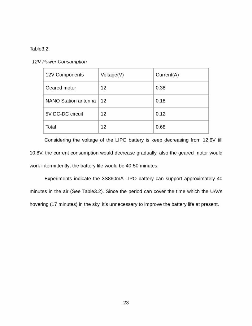
Table3.2.
12V Power Consumption
12V Components Voltage(V) Current(A)
Geared motor 12 0.38
NANO Station antenna 12 0.18
5V DC-DC circuit 12 0.12
Total 12 0.68
Considering the voltage of the LIPO battery is keep decreasing from 12.6V till
10.8V, the current consumption would decrease gradually, also the geared motor would
work intermittently; the battery life would be 40-50 minutes.
Experiments indicate the 3S860mA LIPO battery can support approximately 40
minutes in the air (See Table3.2). Since the period can cover the time which the UAVs
hovering (17 minutes) in the sky, it’s unnecessary to improve the battery life at present.
23
CHAPTER 4
HEADING CONTROL SYSTEM
4.1 Directional Antenna Heading System
In our project, the antenna network system will be integrated together to be a whole
part to install on the UAVs. However, the UAVs will drift and swing, sometimes it’ll change
location to yield birds. All these external factors will change the direction of the NANO
stations. Because the directional characteristic of the antennas, a mechanism is needed
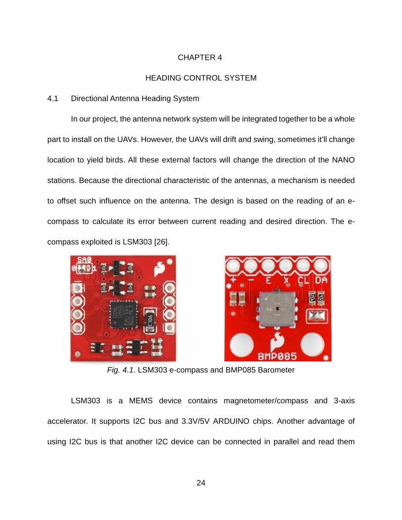
to offset such influence on the antenna. The design is based on the reading of an e-
compass to calculate its error between current reading and desired direction. The e-
compass exploited is LSM303 [26].
Fig. 4.1. LSM303 e-compass and BMP085 Barometer
LSM303 is a MEMS device contains magnetometer/compass and 3-axis
accelerator. It supports I2C bus and 3.3V/5V ARDUINO chips. Another advantage of
using I2C bus is that another I2C device can be connected in parallel and read them
24
separately by their unique device IDs. In the design, a barometer is connected (Fig. 4.1)
to measure its height, so the two I2C devices can be connected without too much trouble.
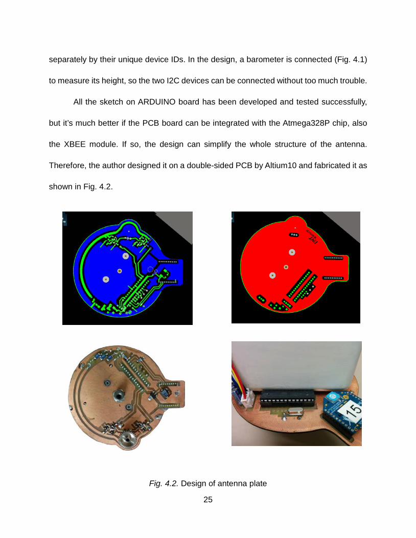
All the sketch on ARDUINO board has been developed and tested successfully,
but it’s much better if the PCB board can be integrated with the Atmega328P chip, also
the XBEE module. If so, the design can simplify the whole structure of the antenna.
Therefore, the author designed it on a double-sided PCB by Altium10 and fabricated it as
shown in Fig. 4.2.
Fig. 4.2. Design of antenna plate
25
The following code is used to generate a timer interrupt to transmit information
once a second by XBEE.
cli();
TCCR1A = 0;// set entire TCCR1A register to 0
TCCR1B = 0;// same for TCCR1B
TCNT1 = 0;//initialize counter value to 0
// set compare match register for 1hz increments
OCR1A = 15624;// = (16*10^6) / (1*1024) - 1 (must be <65536)
// turn on CTC mode
TCCR1B |= (1 << WGM12);
// Set CS12 and CS10 bits for 1024 prescaler
TCCR1B |= (1 << CS12) | (1 << CS10);
// enable timer compare interrupt
TIMSK1 |= (1 << OCIE1A);
sei();
Transmit information to ground once a second; check whether there’s a new
degree request incoming at first. Transmit only when there’s no incoming request.
ISR(TIMER1_COMPA_vect){
if (Serial.available()<1){ //If no incoming inf,
allow transmitting
String temp = dtostrf(temperature*100,5,0,buffer);
String pres = dtostrf(pressure*10,6,0,buffer);
String alti = dtostrf(altitude*100,5,0,buffer);
String output = temp + pres + alti;
output.replace(" ","0"); // Ready for transmission in
ISR
26
Serial.println(output);
}
Trim compass reading to flat the value by average algorithm.
compass.read();
float headingRaw = compass.heading(); // Get heading
from compass
if ( headingRaw - outheading > 300){ // Arithmetic to
eliminate fluctuating
diff = (360 - headingRaw + outheading)/2;
outheading = headingRaw + diff;
if ( outheading > 359 ){ outheading = outheading - 360;}
}
else
{
if ( outheading - headingRaw > 300 ){
diff = (360 - outheading + headingRaw)/2;
outheading = outheading + diff;
if ( outheading > 359 ){ outheading = outheading - 360;}
}
else
{
outheading = (headingRaw +outheading)/2;
}
}
float heading = outheading - targetHeading;
27
// Calculate the module to 360
if ( heading < 0){
heading = 360 + heading;
}
Finally, the code will judge whether the geared motor should drive the antenna to rotate
CW or CCW.
if ( heading < 180 && heading > offsetTol ){
digitalWrite(motor_cw, HIGH);
digitalWrite(motor_ccw, LOW);
}
else if ( heading >= 180 && heading < 359.99 - offsetTol ){
digitalWrite(motor_cw, LOW);
digitalWrite(motor_ccw, HIGH);
}
else {
digitalWrite(motor_cw, LOW);
digitalWrite(motor_ccw, LOW);
}
28
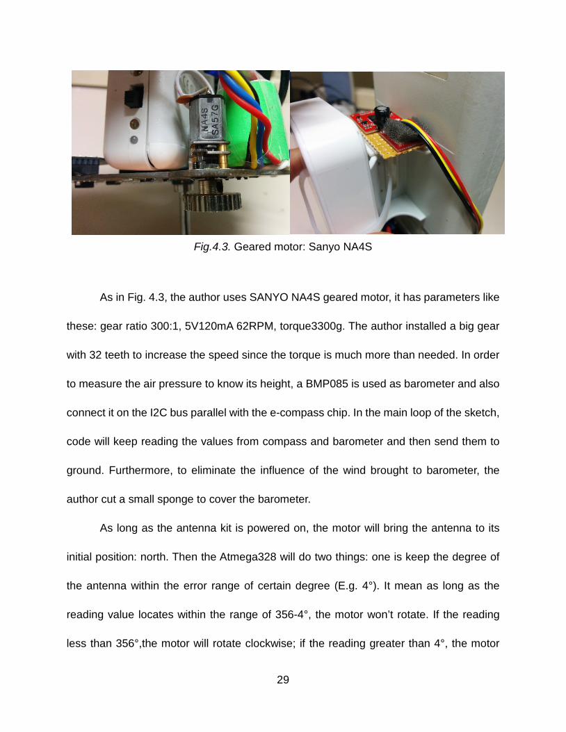
Fig.4.3. Geared motor: Sanyo NA4S
As in Fig. 4.3, the author uses SANYO NA4S geared motor, it has parameters like
these: gear ratio 300:1, 5V120mA 62RPM, torque3300g. The author installed a big gear
with 32 teeth to increase the speed since the torque is much more than needed. In order
to measure the air pressure to know its height, a BMP085 is used as barometer and also
connect it on the I2C bus parallel with the e-compass chip. In the main loop of the sketch,
code will keep reading the values from compass and barometer and then send them to
ground. Furthermore, to eliminate the influence of the wind brought to barometer, the
author cut a small sponge to cover the barometer.
As long as the antenna kit is powered on, the motor will bring the antenna to its
initial position: north. Then the Atmega328 will do two things: one is keep the degree of
the antenna within the error range of certain degree (E.g. 4°). It mean as long as the
reading value locates within the range of 356-4°, the motor won’t rotate. If the reading
less than 356°,the motor will rotate clockwise; if the reading greater than 4°, the motor
29
will rotate counter clockwise. The other one thing is waiting for the desired degree. On
the ground controller, if a new degree other than north is selected and sent; the antenna
will rotate to this desired degree (E.g. 270°), also will keep in the error range (266°-274°).
4.2 Ground Controller
Before taking off, the NANO station antennas should be aligned face to face to
establish connection. When they’re hovering in the air, the two antennas will face to each
other to maintain the connection. However, after powering on, both NANO station
antennas will automatically face to north by requirement of software default. So the author
plans to use a ground controller to adjust the heading degree of the antennas via XBEE
modules. Also, the heading degree can be re-adjusted during flight. At the meantime, the
controller can display other information like altitude and its battery’s voltage. The author
deigned the ground controller on a single side board by Altium10 as well as shown in Fig.
4.4
As displayed on the LCD1602’s screen, the current absolute elevation of the
antenna is 212m with pressure 98804Pa. If the UAVs fly to 20 meters’ high, the screen
will read 232m. To simplify the reading, the author designed a blue button to reset the
current elevation to zero before UAVs take off. When it rise to 20 meters’ high, the screen
will read 20m. Left value on the screen is the heading degree. User can choose a new
degree by adjusting the rotating encoder; when degree is ready, press it and the new
degree will be sent to the antenna. Right value is the current battery’s voltage. The circuit
30
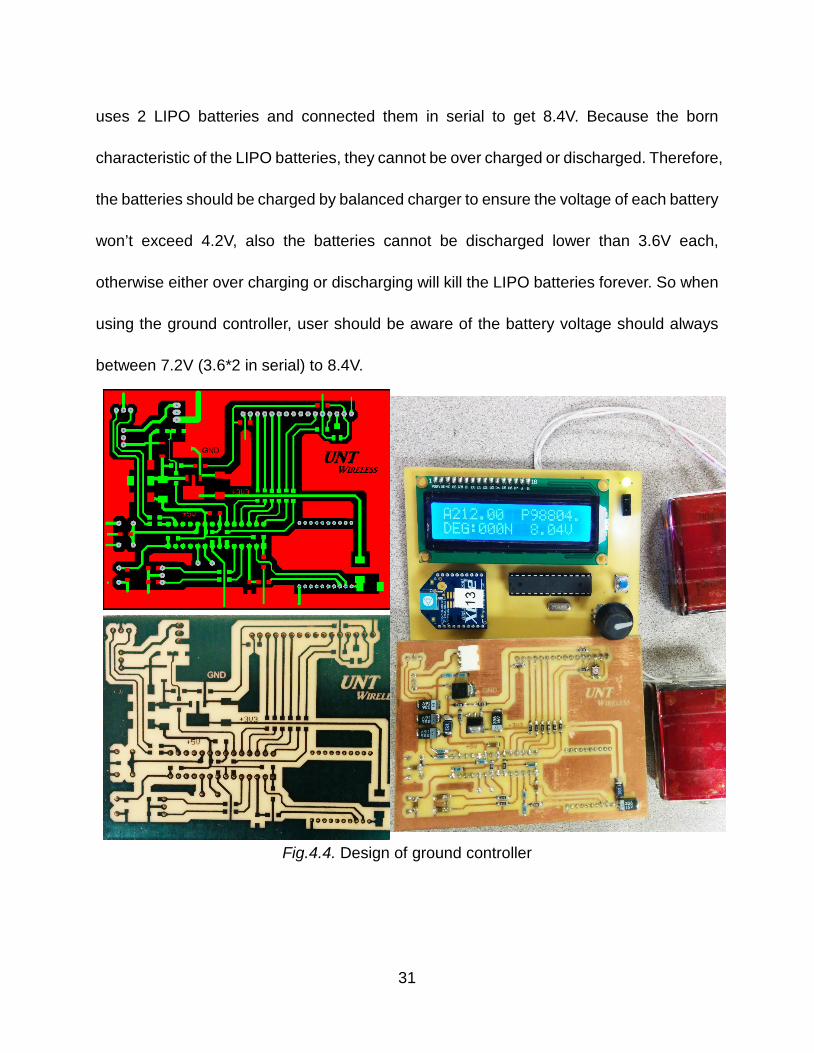
uses 2 LIPO batteries and connected them in serial to get 8.4V. Because the born
characteristic of the LIPO batteries, they cannot be over charged or discharged. Therefore,
the batteries should be charged by balanced charger to ensure the voltage of each battery
won’t exceed 4.2V, also the batteries cannot be discharged lower than 3.6V each,
otherwise either over charging or discharging will kill the LIPO batteries forever. So when
using the ground controller, user should be aware of the battery voltage should always
between 7.2V (3.6*2 in serial) to 8.4V.
Fig.4.4. Design of ground controller
31
4.3 UAVs’ Modification
To rotate the antenna part smoothly, two central holes are drilled on both of the
upper and lower frames, also two stands with 5mm bearings inside are installed. For the
upper frame, a 140 teeth gear is necessary to provide counterforce to antenna part as
shown in Fig. 4.5 .
At the same time, a 5mm’s diameter steel rod with 65mm’s long is cut to be the
spindle of the antenna. Also, one end of the rod was soldered together with the rotating
plate. Since the plate is made by double-sided PCB, the rod was soldered from both sides
to strengthen the structure. Therefore, when the geared motor rotates on the antenna
rotating plate, the gear will engage the big gear installed on the upper frame to generate
the counterforce to drive itself rotating. Because the upper gear is not initially designed
for the application, so the teeth bring too much torque but lowering the speed. The author
will try to find more suitable teeth in the future to get faster rotating response.
32
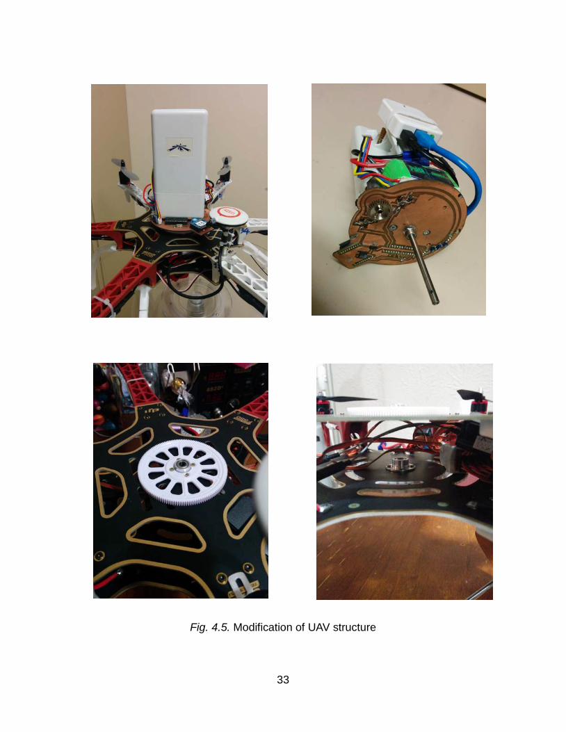
Fig. 4.5. Modification of UAV structure
33
CHAPTER 5
FIELD TEST
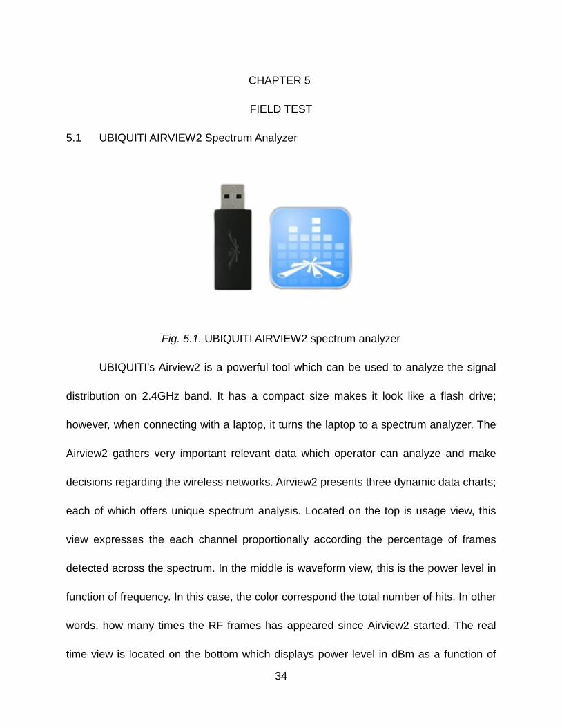
5.1 UBIQUITI AIRVIEW2 Spectrum Analyzer
Fig. 5.1. UBIQUITI AIRVIEW2 spectrum analyzer
UBIQUITI’s Airview2 is a powerful tool which can be used to analyze the signal
distribution on 2.4GHz band. It has a compact size makes it look like a flash drive;
however, when connecting with a laptop, it turns the laptop to a spectrum analyzer. The
Airview2 gathers very important relevant data which operator can analyze and make
decisions regarding the wireless networks. Airview2 presents three dynamic data charts;
each of which offers unique spectrum analysis. Located on the top is usage view, this
view expresses the each channel proportionally according the percentage of frames
detected across the spectrum. In the middle is waveform view, this is the power level in
function of frequency. In this case, the color correspond the total number of hits. In other
words, how many times the RF frames has appeared since Airview2 started. The real
time view is located on the bottom which displays power level in dBm as a function of
34
frequency. The line color correspond the different measurements include the current
energy reading, average energy level and maximum energy signature since Airview2 first
begins. Marks can also be set for specific energy frequency to give more detail description
for power level at any moment and time. Data can be reset at any time simply click the
button on the top right side of the window.
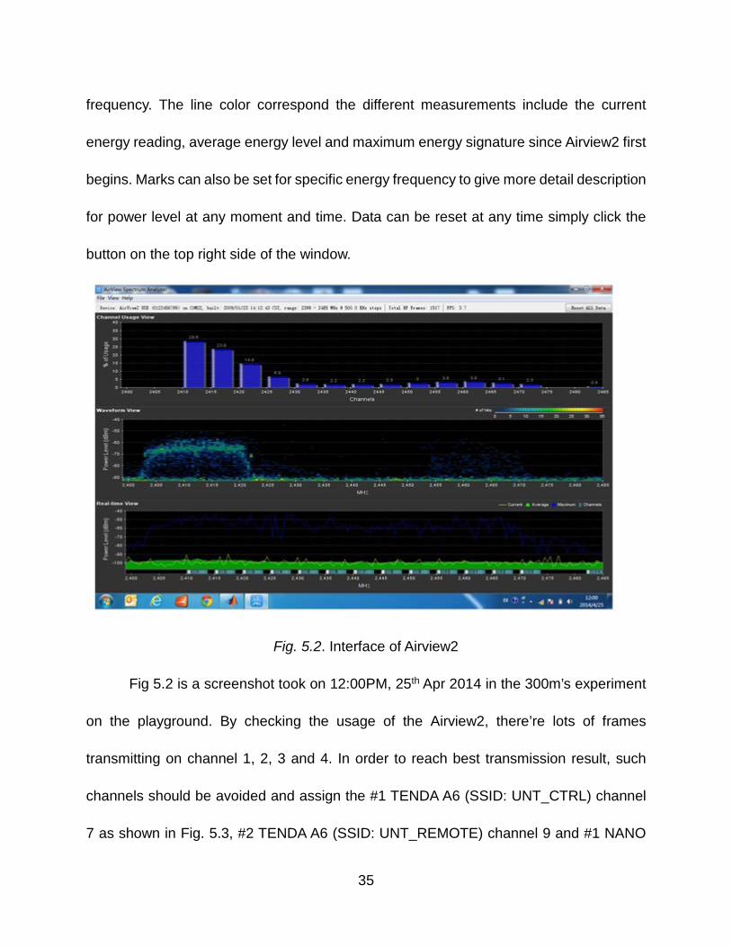
Fig. 5.2. Interface of Airview2
Fig 5.2 is a screenshot took on 12:00PM, 25th Apr 2014 in the 300m’s experiment
on the playground. By checking the usage of the Airview2, there’re lots of frames
transmitting on channel 1, 2, 3 and 4. In order to reach best transmission result, such
channels should be avoided and assign the #1 TENDA A6 (SSID: UNT_CTRL) channel
7 as shown in Fig. 5.3, #2 TENDA A6 (SSID: UNT_REMOTE) channel 9 and #1 NANO
35
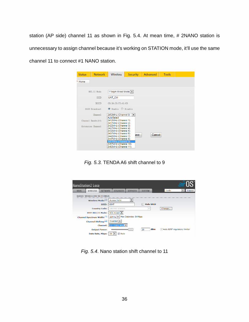
station (AP side) channel 11 as shown in Fig. 5.4. At mean time, # 2NANO station is
unnecessary to assign channel because it’s working on STATION mode, it’ll use the same
channel 11 to connect #1 NANO station.
Fig. 5.3. TENDA A6 shift channel to 9
Fig. 5.4. Nano station shift channel to 11
36
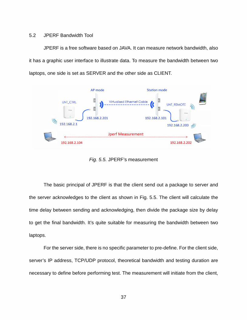
5.2 JPERF Bandwidth Tool
JPERF is a free software based on JAVA. It can measure network bandwidth, also
it has a graphic user interface to illustrate data. To measure the bandwidth between two
laptops, one side is set as SERVER and the other side as CLIENT.
Fig. 5.5. JPERF’s measurement
The basic principal of JPERF is that the client send out a package to server and
the server acknowledges to the client as shown in Fig. 5.5. The client will calculate the
time delay between sending and acknowledging, then divide the package size by delay
to get the final bandwidth. It’s quite suitable for measuring the bandwidth between two
laptops.
For the server side, there is no specific parameter to pre-define. For the client side,
server’s IP address, TCP/UDP protocol, theoretical bandwidth and testing duration are
necessary to define before performing test. The measurement will initiate from the client,
37
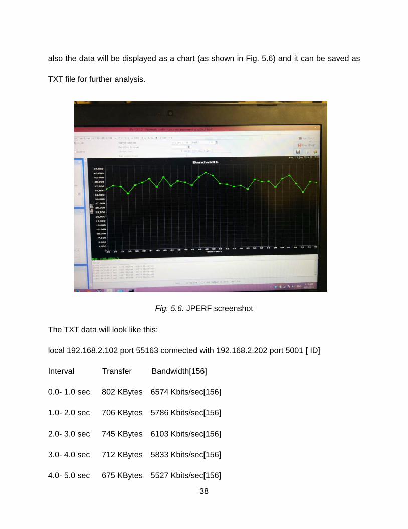
also the data will be displayed as a chart (as shown in Fig. 5.6) and it can be saved as
TXT file for further analysis.
Fig. 5.6. JPERF screenshot
The TXT data will look like this:
local 192.168.2.102 port 55163 connected with 192.168.2.202 port 5001 [ ID]
Interval Transfer Bandwidth[156]
0.0- 1.0 sec 802 KBytes 6574 Kbits/sec[156]
1.0- 2.0 sec 706 KBytes 5786 Kbits/sec[156]
2.0- 3.0 sec 745 KBytes 6103 Kbits/sec[156]
3.0- 4.0 sec 712 KBytes 5833 Kbits/sec[156]
4.0- 5.0 sec 675 KBytes 5527 Kbits/sec[156]
38
5.0- 6.0 sec 693 KBytes 5680 Kbits/sec[156]
6.0- 7.0 sec 825 KBytes 6762 Kbits/sec[156]
7.0- 8.0 sec 780 KBytes 6386 Kbits/sec[156]
8.0- 9.0 sec 290 KBytes 2376 Kbits/sec[156]
9.0-10.0 sec 423 KBytes 3469 Kbits/sec[156]
Transfer Bandwidth[156]
0.0-10.0 sec 6252 KBytes 5121 Kbits/sec[156]
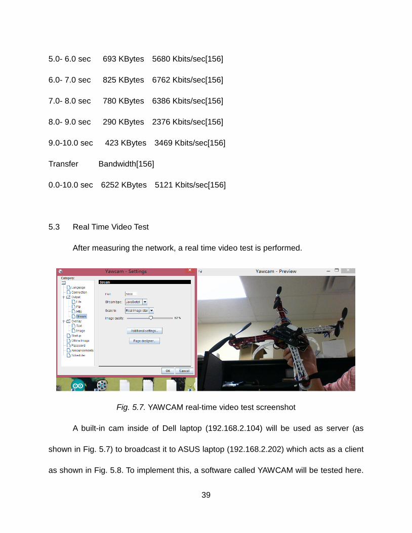
5.3 Real Time Video Test
After measuring the network, a real time video test is performed.
Fig. 5.7. YAWCAM real-time video test screenshot
A built-in cam inside of Dell laptop (192.168.2.104) will be used as server (as
shown in Fig. 5.7) to broadcast it to ASUS laptop (192.168.2.202) which acts as a client
as shown in Fig. 5.8. To implement this, a software called YAWCAM will be tested here.
39
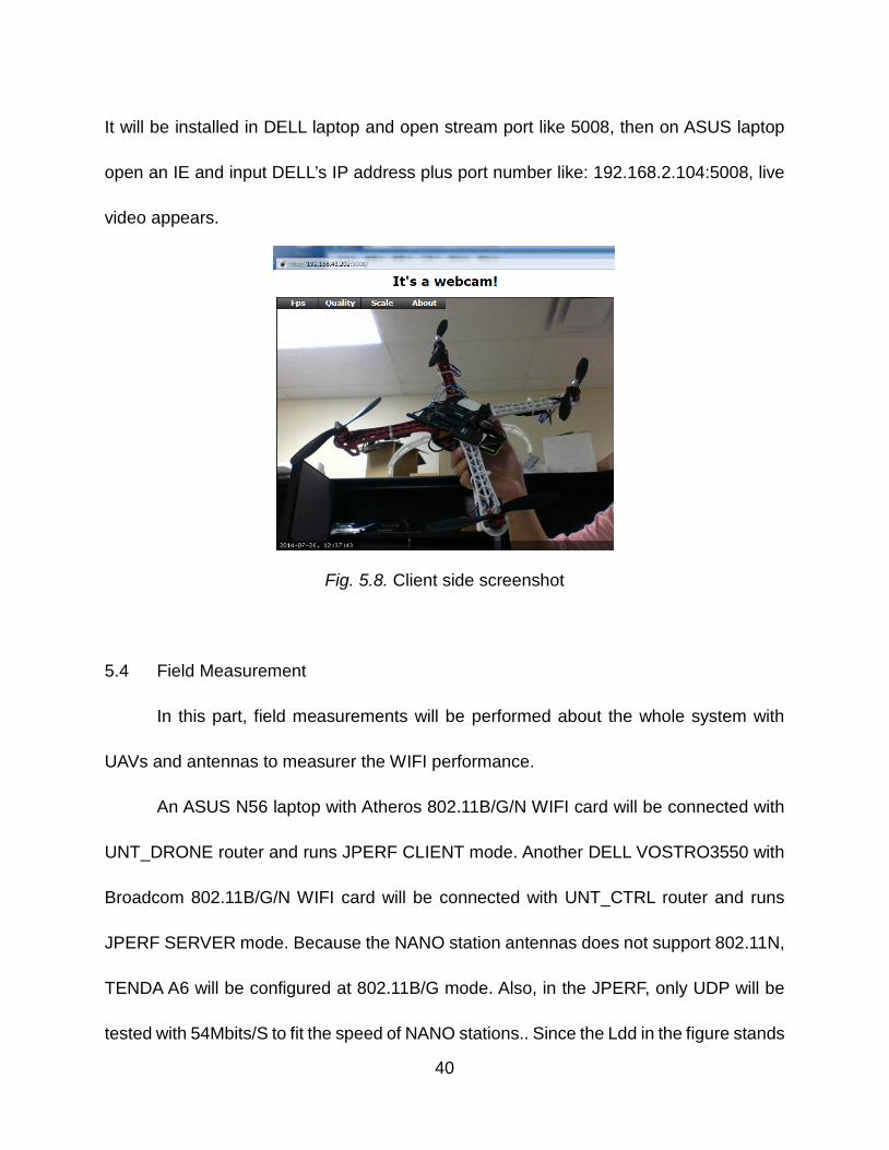
It will be installed in DELL laptop and open stream port like 5008, then on ASUS laptop
open an IE and input DELL’s IP address plus port number like: 192.168.2.104:5008, live
video appears.
Fig. 5.8. Client side screenshot
5.4 Field Measurement
In this part, field measurements will be performed about the whole system with
UAVs and antennas to measurer the WIFI performance.
An ASUS N56 laptop with Atheros 802.11B/G/N WIFI card will be connected with
UNT_DRONE router and runs JPERF CLIENT mode. Another DELL VOSTRO3550 with
Broadcom 802.11B/G/N WIFI card will be connected with UNT_CTRL router and runs
JPERF SERVER mode. Because the NANO station antennas does not support 802.11N,
TENDA A6 will be configured at 802.11B/G mode. Also, in the JPERF, only UDP will be
tested with 54Mbits/S to fit the speed of NANO stations.. Since the Ldd in the figure stands
40
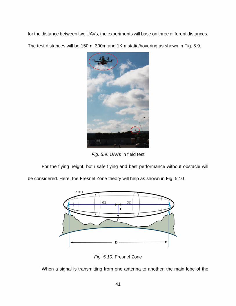
for the distance between two UAVs, the experiments will base on three different distances.
The test distances will be 150m, 300m and 1Km static/hovering as shown in Fig. 5.9.
Fig. 5.9. UAVs in field test
For the flying height, both safe flying and best performance without obstacle will
be considered. Here, the Fresnel Zone theory will help as shown in Fig. 5.10
Fig. 5.10. Fresnel Zone
When a signal is transmitting from one antenna to another, the main lobe of the
41
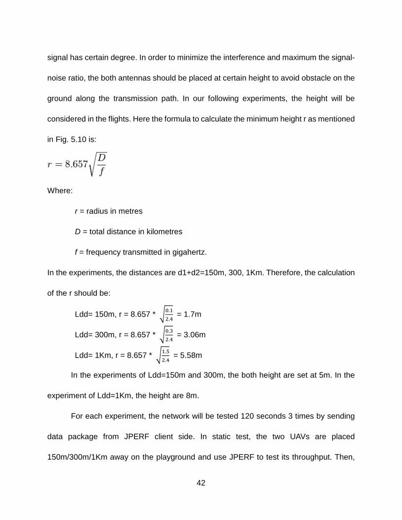
signal has certain degree. In order to minimize the interference and maximum the signal-
noise ratio, the both antennas should be placed at certain height to avoid obstacle on the
ground along the transmission path. In our following experiments, the height will be
considered in the flights. Here the formula to calculate the minimum height r as mentioned
in Fig. 5.10 is:
Where:
r = radius in metres
D = total distance in kilometres
f = frequency transmitted in gigahertz.
In the experiments, the distances are d1+d2=150m, 300, 1Km. Therefore, the calculation
of the r should be:
Ldd= 150m, r = 8.657 * �0.12.4
= 1.7m
Ldd= 300m, r = 8.657 * �0.32.4
= 3.06m
Ldd= 1Km, r = 8.657 * �1.52.4
= 5.58m
In the experiments of Ldd=150m and 300m, the both height are set at 5m. In the
experiment of Ldd=1Km, the height are 8m.
For each experiment, the network will be tested 120 seconds 3 times by sending
data package from JPERF client side. In static test, the two UAVs are placed
150m/300m/1Km away on the playground and use JPERF to test its throughput. Then,
42
the both drones will hover in the air, also the throughput will be tested by JPERF. Data
has been generated to curves by MATLAB, three colors red, blue and carmine stand for
three experiments’ results.
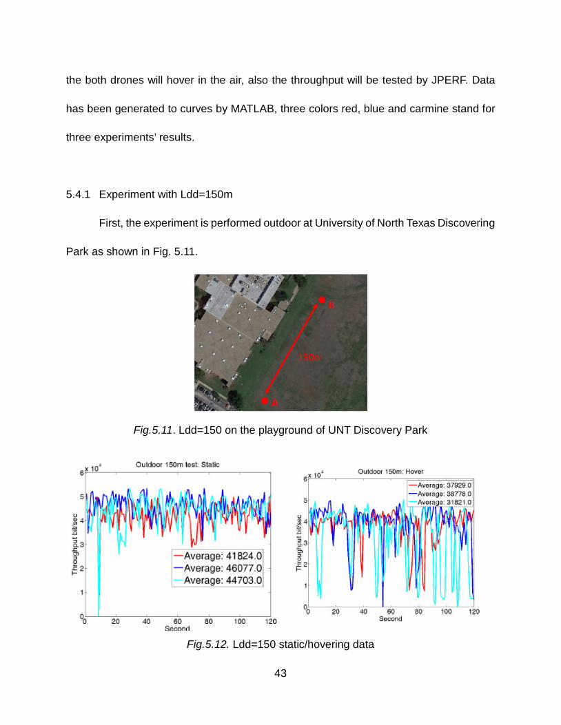
5.4.1 Experiment with Ldd=150m
First, the experiment is performed outdoor at University of North Texas Discovering
Park as shown in Fig. 5.11.
Fig.5.11. Ldd=150 on the playground of UNT Discovery Park
Fig.5.12. Ldd=150 static/hovering data
43
From Fig. 5.12, the throughput of the network decreases from static 44Mbits/S to
hovering 36Mbits/S. Although the UAVs are supposed to be fixed in the air, but sometime
they drift and vibrate caused by wind. In the figure the notches indicate there are lots of
delay occurred due to wind interferences, but they are quickly corrected by automatic
heading system.
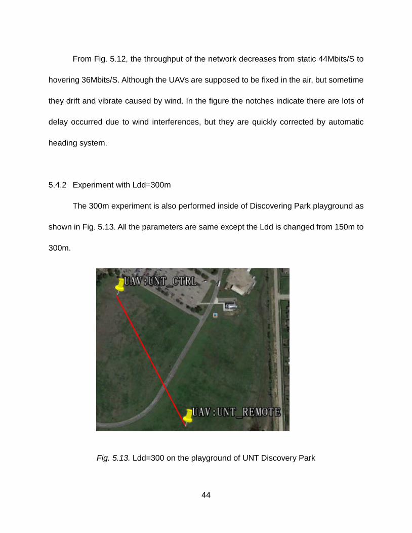
5.4.2 Experiment with Ldd=300m
The 300m experiment is also performed inside of Discovering Park playground as
shown in Fig. 5.13. All the parameters are same except the Ldd is changed from 150m to
300m.
Fig. 5.13. Ldd=300 on the playground of UNT Discovery Park
44
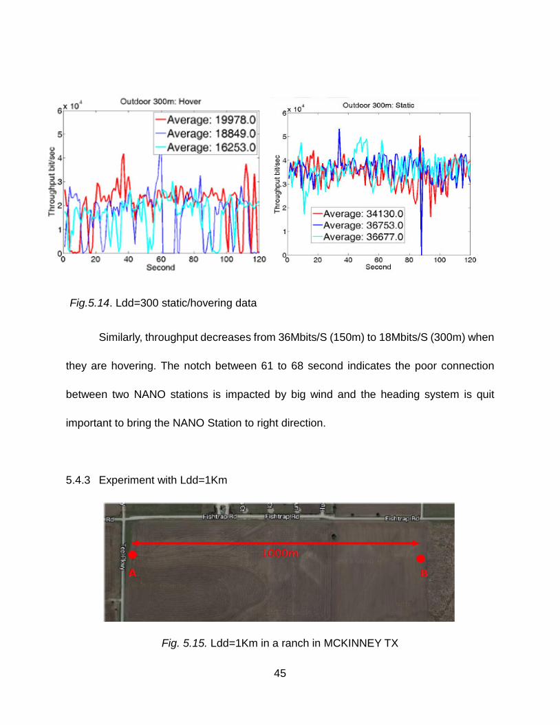
The Fig. 5.14 above indicate
that by the increases of the distance,
the throughput decreases from
44Mbits/S (150m) to 35Mbitys/S
(300m) when they are static as shown
Similarly, throughput decreases from 36Mbits/S (150m) to 18Mbits/S (300m) when
they are hovering. The notch between 61 to 68 second indicates the poor connection
between two NANO stations is impacted by big wind and the heading system is quit
important to bring the NANO Station to right direction.
5.4.3 Experiment with Ldd=1Km
Fig. 5.15. Ldd=1Km in a ranch in MCKINNEY TX
Fig.5.14. Ldd=300 static/hovering data
45
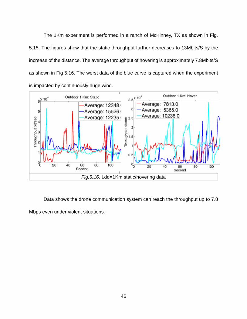
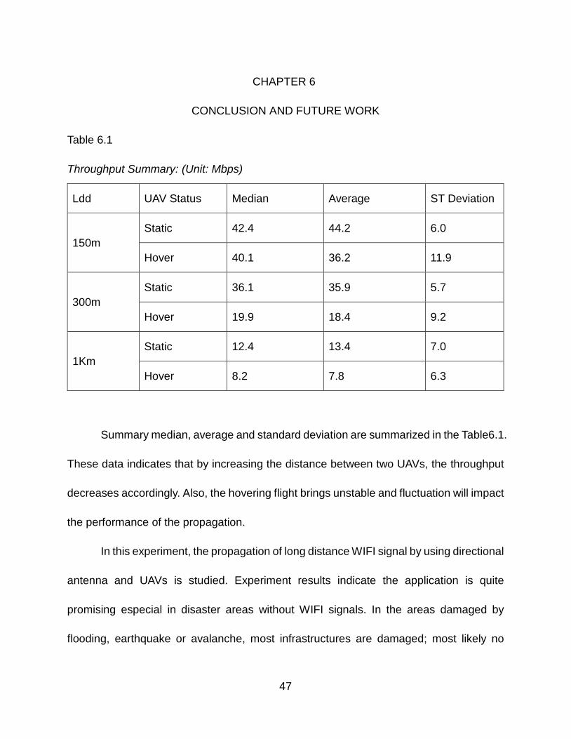
The 1Km experiment is performed in a ranch of McKinney, TX as shown in Fig.
5.15. The figures show that the static throughput further decreases to 13Mbits/S by the
increase of the distance. The average throughput of hovering is approximately 7.8Mbits/S
as shown in Fig 5.16. The worst data of the blue curve is captured when the experiment
is impacted by continuously huge wind.
Fig.5.16. Ldd=1Km static/hovering data
Data shows the drone communication system can reach the throughput up to 7.8
Mbps even under violent situations.
46
CHAPTER 6
CONCLUSION AND FUTURE WORK
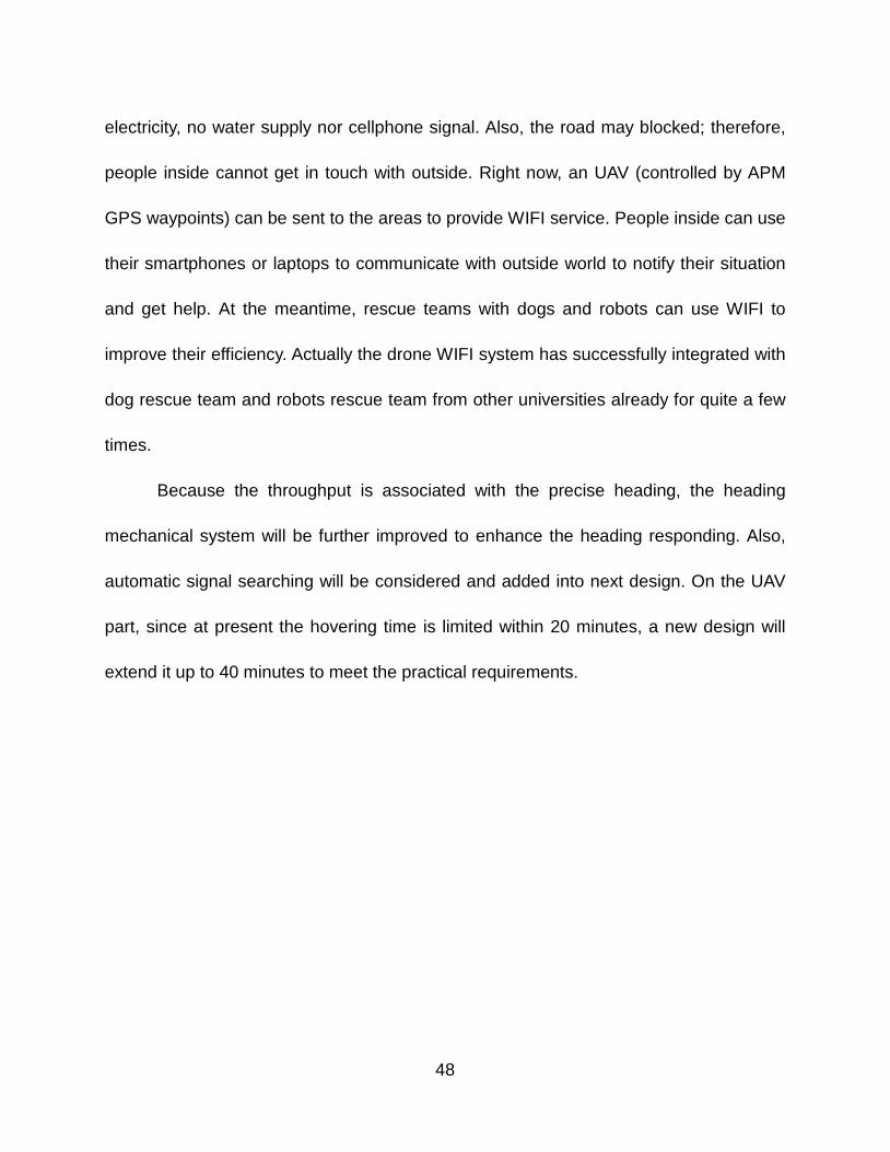
Table 6.1
Throughput Summary: (Unit: Mbps)
Ldd UAV Status Median Average ST Deviation
150m Static 42.4 44.2 6.0
Hover 40.1 36.2 11.9
300m Static 36.1 35.9 5.7
Hover 19.9 18.4 9.2
1Km Static 12.4 13.4 7.0
Hover 8.2 7.8 6.3
Summary median, average and standard deviation are summarized in the Table6.1.
These data indicates that by increasing the distance between two UAVs, the throughput
decreases accordingly. Also, the hovering flight brings unstable and fluctuation will impact
the performance of the propagation.
In this experiment, the propagation of long distance WIFI signal by using directional
antenna and UAVs is studied. Experiment results indicate the application is quite
promising especial in disaster areas without WIFI signals. In the areas damaged by
flooding, earthquake or avalanche, most infrastructures are damaged; most likely no
47
electricity, no water supply nor cellphone signal. Also, the road may blocked; therefore,
people inside cannot get in touch with outside. Right now, an UAV (controlled by APM
GPS waypoints) can be sent to the areas to provide WIFI service. People inside can use
their smartphones or laptops to communicate with outside world to notify their situation
and get help. At the meantime, rescue teams with dogs and robots can use WIFI to
improve their efficiency. Actually the drone WIFI system has successfully integrated with
dog rescue team and robots rescue team from other universities already for quite a few
times.
Because the throughput is associated with the precise heading, the heading
mechanical system will be further improved to enhance the heading responding. Also,
automatic signal searching will be considered and added into next design. On the UAV
part, since at present the hovering time is limited within 20 minutes, a new design will
extend it up to 40 minutes to meet the practical requirements.
48
REFERENCES
[1] C. Dixon and E. W. Frew, “Optimizing Cascaded Chains of Unmanned Aircraft Acting as Communication Relays,” IEEE Journal on Selected Areas in Communications, vol. 30, no. 5, pp. 883–898, June 2012.
[2] M. Asadpour, D. Giustiniano, K. A. Hummel, and S. Heimlicher, “Characterizing 802.11n Aerial Communication,” in Proc. ACM MobiHoc Workshop on Airborne Networks and Communications, pp. 7–11, July2013.
[3] I. Bekmezci, O. K. Sahingoz, and S. Temel, “Flying Ad-hoc Networks (FANETs): A Survey,” Ad Hoc Networks, vol. 11, pp. 1254–1270, 2013.
[4] B. P. Gerkey, R. Mailler and B. Morisset, “Commbots: Distributed Control of Mobile Communication Relays,” in Proc. AAAI Workshop on Auction Mechanisms for Robot Coordination pp. 51–55, Boston, Massachusetts, July 17, 2006.
[5] P. Piper and M. Ramos, “A Failure to Communicate Politics, Scams, and Information Flow During Hurricane Katrina,” Searcher, Vol. 14 No. 6, June 2006.
[6] M. Tortonesi, C. Stefanelli, E. Benvegnu, K. Ford, N. Suri, and M. Linderman, “Multiple-UAV Coordination and Communications in Tactical Edge Networks,” IEEE Communications Magazine, vol. 50, no. 10, pp. 48–55, 2012.
[7] B. Cheng, R. Charland, P. Christensen, L. Veytser and J. Wheeler, “Evaluation of a Multihop Airbonre IP Backbone with Heterogeneous Radio Technologies,” IEEE Transactions on Mobile Computing, pp. 299–310, Vol. 13, No. 2, February 2014.
[8] H. T. Kung, C.-K. Lin, T.-H. Lin, S. J. Tarsa, and D. Vlah, “Measuring Receiver Diversity on a Low-Altitude UAV in a Ground-to-Air Wireless Mesh Network,” in Proc. IEEE Globecom Workshop on Wi-UAV Wireless Networking for Unmanned Autonomous Vehicles, 2010.
[9] J. Bicket, D. Aguayo, S. Biswas and R. Morris, “Architecture and Evaluation of an Unplanned 802.11b Mesh Network,” in Proceedings of MobiCom, Cologne, Germany, August, 2005.
[10] R. Jain and F. Templin, “Requirements, Challenges and Analysis of Alternatives for Wireless Datalinks for Unmanned Aircraft Systems,” IEEE Journal on Selected Aeras in Communications pp. 852–860, vol. 30, no. 5, June 2012.
[11] J. Allred, A. B. Hasan, S. Panichsakul, W. Pisano, P. Gray, J. Huang, R. Han, D. Lawrence and K. Mohseni, “SensorFlock, An Airborne Wireless Sensor Network of
49
Micro-Air Vehicles,” in Proceedings of SenSys 07, November 6–9, Sydney, Australia, 2007.
[12] T. X. Brown, B. Argrow, C. Dixon, S. Doshi, R.-G. Thekkekunel, and D. Henkel, “Ad Hoc UAV Ground Network (AUGNet),” in Proceedings of AIAA 3rd “Unmanned Unlimited” Technical Conference, Workshop and Exhibit, Chicago, Illinois, September 2004.
[13] E. Yanmaz, R. Kuschnig and C. Bettstetter, “Achieving Air-Ground Communications in 802.11 Networks with Three-Dimensional Aerial Mobility,” in Proceedings of IEEE INFOCOM, 2013.
[14] H. T. Kung, C.-K. Lin, T.-H. Lin, S. J. Tarsa and D. Vlah, “Measuring Diversity on a Low-Altitude UAV in a Ground-to-Air Wireless 802.11 Mesh Network”, in Proceedings of Globecom, 2010.
[15] APM, [On-line]. Available: http://ardupilot.com/
[16] IPERF, [On-line]. Available: http://sourceforge.net/projects/IPERF/.
[17] DJI, [On-line]. Available: http://www.dji.com.
[18] UBIAQUITI Networks, [On-line]. Available: http://www.ubnt.com.
[19] TENDA Technology, [On-line]. Available: http://www.tenda.cn.
[20] ARDUINO, [On-line]. Available: www.arduino.cc.
[21] DIJI, [On-line]. Available: http://www.digi.com/xbee/.
[22] DSSS, [On-line].Available: http://en.wikipedia.org/wiki/Direct-sequence_spread_spectrum
[23] Constantine A.Balanis, Antenna Theory Analysis and Design:John Wiley & Sons,Inc. 2005
[24] LM2596, [On-line].Available:http://www.ti.com/product/LM2596?keyMatch=lm2596&tisearch=Search-EN
[25] LSM303, [On-line].Available: https://www.sparkfun.com/products/retired/9810
[26] YAWCAM, [On-line].Available: http://www.yawcam.com/
50