air handling g2 units - krueger-hvac | cellence in air distriution c i r r u s kah indoor unit...
TRANSCRIPT

AIR
HA
ND
LING
UN
ITS
AIR HANDLING UNITS
G2-1
G2
www.krueger-hvac.com | Excellence in Air DistributionG2-2
© K
RU
EG
ER
2015
AIR HANDLING UNITSF2A
IR H
AN
DLI
NG
UN
ITS
Table of Contents
KAHThis air handling unit features an array of features and options to design a custom solution to meet your application needs.
KAHIntroduction........................................................................................................G2-3Product Description ...........................................................................................G2-4Chilled Water / Hot Water and Direct Expansion (DX) Segment .......................G2-12Heating Coils Segment......................................................................................G2-13Fan Segment .....................................................................................................G2-14Cooling Coil and Heating Coil Segment ............................................................G2-18Vertical Coil Segment ........................................................................................G2-19Angle Wall & Back to Back Design ....................................................................G2-20Multi-Zone Segment ..........................................................................................G2-21Integral Face & Bypass Segment ......................................................................G2-22Indirect Gas-Fired Furnace Segment ................................................................G2-23Electric Heat Segment ......................................................................................G2-24Energy Recovery Wheel Segment ....................................................................G2-25Mixing Box / Mixing Segment ............................................................................G2-26Economizer .......................................................................................................G2-27Face Damper & Inlet Plenum ............................................................................G2-29Diffuser Segment ...............................................................................................G2-30Vertical Plenum & Discharge Plenum................................................................G2-31Sound Attenuator...............................................................................................G2-32Air Blender / Air Mixer........................................................................................G2-33Internal / External Face & Bypass .....................................................................G2-34Humidifier Segment ...........................................................................................G2-35Turning Segments .............................................................................................G2-36UV Segment ......................................................................................................G2-37Pipe Chase Enclosure .......................................................................................G2-38Factory-Packaged Controls ...............................................................................G2-39Power Wiring Options........................................................................................G2-40Door and Discharge Locations ..........................................................................G2-41Testing & Certifications ......................................................................................G2-42
Providing You With Air Distribution Solutions G2-3
CIRRUS
KAH | Indoor Unit©
KR
UE
GE
R 2
015
AIR HANDLING UNITS F2A
IR H
AN
DLIN
G U
NITS
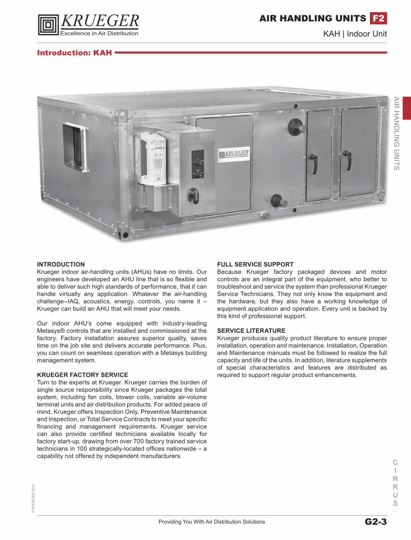
INTRODUCTIONKrueger indoor air-handling units (AHUs) have no limits. Our engineers have developed an AHU line that is so flexible and able to deliver such high standards of performance, that it can handle virtually any application. Whatever the air-handling challenge–IAQ, acoustics, energy, controls, you name it – Krueger can build an AHU that will meet your needs.
Our indoor AHU’s come equipped with industry-leading Metasys® controls that are installed and commissioned at the factory. Factory installation assures superior quality, saves time on the job site and delivers accurate performance. Plus, you can count on seamless operation with a Metasys building management system.
KRUEGER FACTORY SERVICETurn to the experts at Krueger. Krueger carries the burden of single source responsibility since Krueger packages the total system, including fan coils, blower coils, variable air-volume terminal units and air distribution products. For added peace of mind, Krueger offers Inspection Only, Preventive Maintenance and Inspection, or Total Service Contracts to meet your specific financing and management requirements. Krueger service can also provide certified technicians available locally for factory start-up, drawing from over 700 factory trained service technicians in 100 strategically-located offices nationwide – a capability not offered by independent manufacturers.
FULL SERVICE SUPPORTBecause Krueger factory packaged devices and motor controls are an integral part of the equipment, who better to troubleshoot and service the system than professional Krueger Service Technicians. They not only know the equipment and the hardware, but they also have a working knowledge of equipment application and operation. Every unit is backed by this kind of professional support.
SERVICE LITERATUREKrueger produces quality product literature to ensure proper installation, operation and maintenance. Installation, Operation and Maintenance manuals must be followed to realize the full capacity and life of the units. In addition, literature supplements of special characteristics and features are distributed as required to support regular product enhancements.
Introduction: KAH
www.krueger-hvac.com | Excellence in Air DistributionG2-4
CIRRUS
KAH | Indoor Unit©
KR
UE
GE
R 2015
AIR HANDLING UNITSF2A
IR H
AN
DLI
NG
UN
ITS
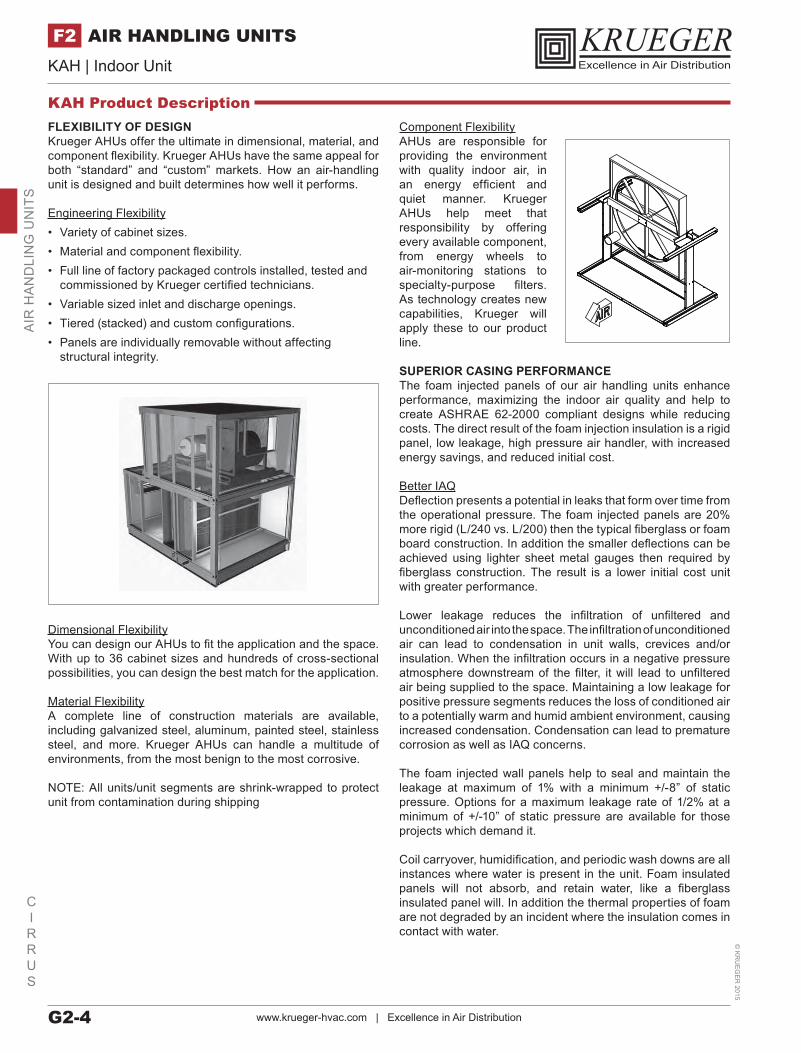
Component FlexibilityAHUs are responsible for providing the environment with quality indoor air, in an energy efficient and quiet manner. Krueger AHUs help meet that responsibility by offering every available component, from energy wheels to air-monitoring stations to specialty-purpose filters. As technology creates new capabilities, Krueger will apply these to our product line.
SUPERIOR CASING PERFORMANCEThe foam injected panels of our air handling units enhance performance, maximizing the indoor air quality and help to create ASHRAE 62-2000 compliant designs while reducing costs. The direct result of the foam injection insulation is a rigid panel, low leakage, high pressure air handler, with increased energy savings, and reduced initial cost.
Better IAQDeflection presents a potential in leaks that form over time from the operational pressure. The foam injected panels are 20% more rigid (L/240 vs. L/200) then the typical fiberglass or foam board construction. In addition the smaller deflections can be achieved using lighter sheet metal gauges then required by fiberglass construction. The result is a lower initial cost unit with greater performance.
Lower leakage reduces the infiltration of unfiltered and unconditioned air into the space. The infiltration of unconditioned air can lead to condensation in unit walls, crevices and/or insulation. When the infiltration occurs in a negative pressure atmosphere downstream of the filter, it will lead to unfiltered air being supplied to the space. Maintaining a low leakage for positive pressure segments reduces the loss of conditioned air to a potentially warm and humid ambient environment, causing increased condensation. Condensation can lead to premature corrosion as well as IAQ concerns.
The foam injected wall panels help to seal and maintain the leakage at maximum of 1% with a minimum +/-8” of static pressure. Options for a maximum leakage rate of 1/2% at a minimum of +/-10” of static pressure are available for those projects which demand it.
Coil carryover, humidification, and periodic wash downs are all instances where water is present in the unit. Foam insulated panels will not absorb, and retain water, like a fiberglass insulated panel will. In addition the thermal properties of foam are not degraded by an incident where the insulation comes in contact with water.
FLEXIBILITY OF DESIGNKrueger AHUs offer the ultimate in dimensional, material, and component flexibility. Krueger AHUs have the same appeal for both “standard” and “custom” markets. How an air-handling unit is designed and built determines how well it performs.
Engineering Flexibility• Variety of cabinet sizes.• Material and component flexibility.• Full line of factory packaged controls installed, tested and
commissioned by Krueger certified technicians.• Variable sized inlet and discharge openings.• Tiered (stacked) and custom configurations.• Panels are individually removable without affecting
structural integrity.
Dimensional FlexibilityYou can design our AHUs to fit the application and the space. With up to 36 cabinet sizes and hundreds of cross-sectional possibilities, you can design the best match for the application.
Material FlexibilityA complete line of construction materials are available, including galvanized steel, aluminum, painted steel, stainless steel, and more. Krueger AHUs can handle a multitude of environments, from the most benign to the most corrosive.
NOTE: All units/unit segments are shrink-wrapped to protect unit from contamination during shipping
KAH Product Description
Providing You With Air Distribution Solutions G2-5
CIRRUS
KAH | Indoor Unit©
KR
UE
GE
R 2
015
AIR HANDLING UNITS F2A
IR H
AN
DLIN
G U
NITS
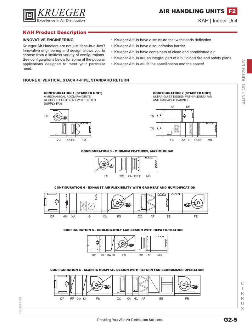
INNOVATIVE ENGINEERING Krueger Air Handlers are not just ‘fans-in-a-box’! Innovative engineering and design allows you to choose from a limitless variety of configurations. See configurations below for some of the popular applications designed to meet your particular need.
FIGURE 8: VERTICAL STACK 4-PIPE, STANDARD RETURN
FS CC XA HC FF MB
FS CCDIXADP HF RF MB
FS CC XA HCDIXARFDP AF EE FR
XADP FS CC AFHM IG XA EE FE
CONFIGURATION 3 - MINIMUM FEATURES, MAXIMUM IAQ
CONFIGURATION 1 (STACKED UNIT)A MECHANICAL ROOM FAVORITE. REDUCED FOOTPRINT WITH TIEREDSUPPLY FAN.
CONFIGURATION 2 (STACKED UNIT)ULTRA-QUIET DESIGN WITH PLENUM FAN AND U-SHAPED CABINET.
CONFIGURATION 4 - EXHAUST AIR FLEXIBILITY WITH GAS-HEAT AND HUMIDIFICATION
CONFIGURATION 5 - COOLING-ONLY LAB DESIGN WITH HEPA FILTRATION
CONFIGURATION 6 - CLASSIC HOSPITAL DESIGN WITH RETURN FAN ECONOMIZER OPERATION
XAFS
DPAT
XA
TN
TN
E RF MB
FS
VC FMXA HC
• Krueger AHUs have a structure that withstands deflection.• Krueger AHUs have a sound/noise barrier.• Krueger AHUs have containers of clean and conditioned air.• Krueger AHUs are an integral part of a building’s fire and safety plans.• Krueger AHUs will fit the specification and the space!
KAH Product Description
www.krueger-hvac.com | Excellence in Air DistributionG2-6
CIRRUS
KAH | Indoor Unit©
KR
UE
GE
R 2015
AIR HANDLING UNITSF2A
IR H
AN
DLI
NG
UN
ITS
FAN SEGMENTS• FS – Supply - Forward Curved - Airfoil - Industrial Airfoil - SWSI Plenum (Belt and Direct Drive)• FR – Return - Forward Curved - Airfoil - Industrial Airfoil - SWSI Plenum (Belt and Direct Drive)• FE – Exhaust - Forward Curved - Airfoil - Industrial Airfoil
COIL SEGMENTS• CC – Cooling Coil• HC – Heating Coil• VC – Vertical Coil• MZ – Multizone
HEAT SEGMENTS• IC – Integral Face & Bypass Coil• IG – Indirect Gas Fired Furnace• EH – Electric Heater
ENERGY RECOVERY• ER – Energy Recovery
FILTER SEGMENTS• FF – Flat Filter (2” or 4”)• AF – Angle Filter (2” & 4”)• RF – High Efficiency Filter• Rigid Filter (12”)• Bag Filter (21”)• Mini-Pleat Filter (4”)• HF – HEPA Filter
INLET SEGMENTS• MB – Mixing Box• FM – Filter/Mixing Box• EF – Filter/Economizer• EE – Economizer• IP – Inlet Plenum• VE – Vertical Economizer• VF – Vertical Filter / Economizer
ACCESSORY SEGMENTS• VP – Vertical Plenum• DP – Discharge Plenum• TN – Turning Plenum• DI – Diffuser• XA – Access Segment• AB – Air Blender• EB – External Bypass• IB – Internal Bypass• FD – Face Damper• AT – Attenuator• HM – Humidifier• UV – UVC Lamps
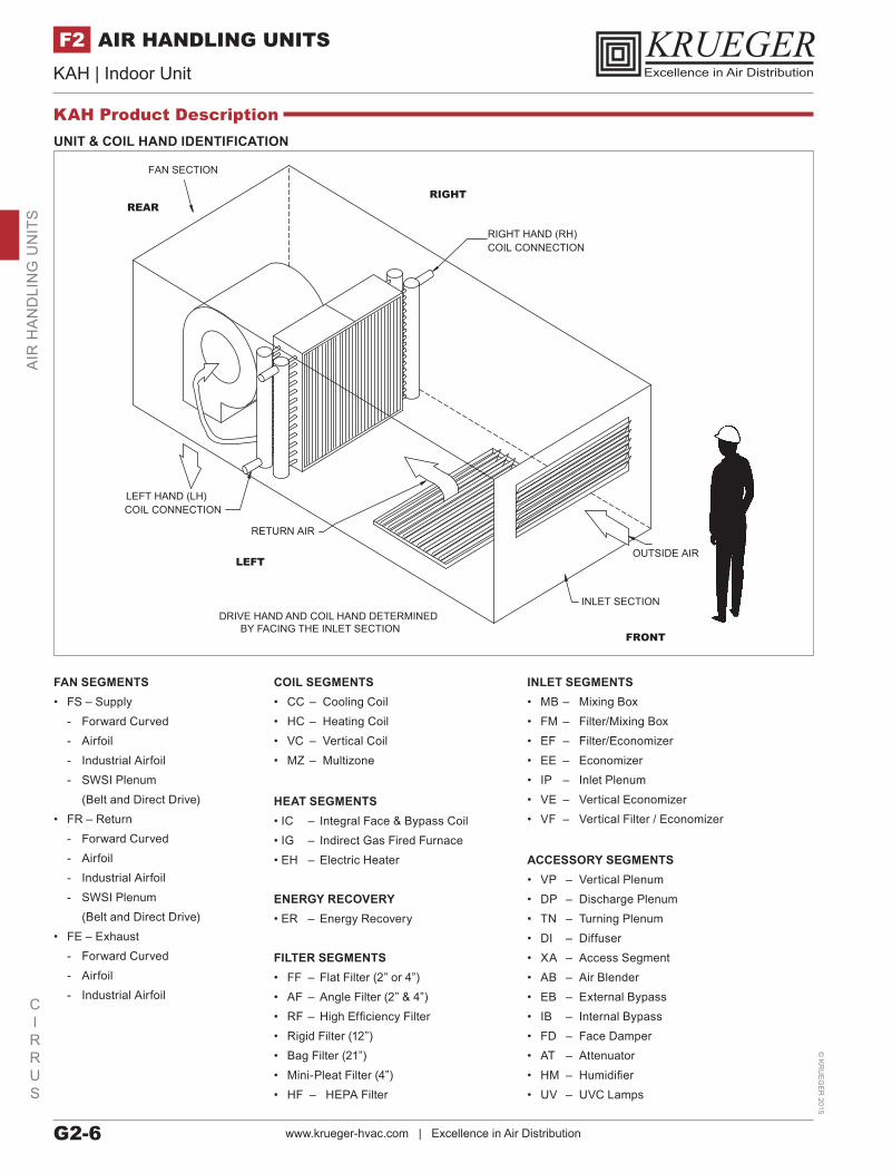
UNIT & COIL HAND IDENTIFICATION
FAN SECTION
LEFT HAND (LH) COIL CONNECTION
RIGHT HAND (RH) COIL CONNECTION
RETURN AIR
INLET SECTION
OUTSIDE AIR
DRIVE HAND AND COIL HAND DETERMINEDBY FACING THE INLET SECTION
RIGHTREAR
LEFT
FRONT
KAH Product Description
Providing You With Air Distribution Solutions G2-7
CIRRUS
KAH | Indoor Unit©
KR
UE
GE
R 2
015
AIR HANDLING UNITS F2A
IR H
AN
DLIN
G U
NITS
ENERGY SAVINGSThe energy savings associated with high performing air handler construction is directly associated with leakage and insulating properties.
The infiltration of unconditioned air downstream of a coil, or the loss of conditioned air downstream of a coil are just two examples of reduced energy efficiency in an air handler. The foam injected panel helps to reduce both of these potential losses by creating a more rigid, lower leakage air handling over the life of the unit.
Another form of energy loss associated with air handlers is the thermal energy that is lost through the cabinet of the air handler. The foam injected panels lower energy consumption with better insulating properties. With the standard R-12.5 and optional R-18.8, or R-25, it can help to reduce the energy usage. The injected panel provides additional thermal advantages in that the foam will fill voids, and gaps that aren’t reached with fiberglass or foam board type constructions.
Krueger air handler units are capable of being factory tested to prove out both leakage and deflection. With this product, it’s not all about construction, it’s also about performance.
PRE-ENGINEERING PACKAGED CONTROLSPre-engineering of sensors ensures the most accurate performance. There are great advantages to selecting factory mounted and wired end devices for your air handling units.
• Factory mounting maintains leakage performance.• Factory wiring is plug and play.• Factory testing of each mounted and wired device.• Factory generated control diagrams specifically for each unit.
Factory InstallationFactory installation improves quality and saves time. While the AHU is being manufactured, Krueger technicians can easily access all its segments, so there are no accessibility problems to cramp the quality of the controls installation, which often occurs on the job site.
All sensor probes have been pre-engineered to determine the best mounting location, ensuring accurate and reliable readings.
This improves performance of the unit while eliminating unwanted air leakage common in field-mounted solutions.
Factory Engineering Speeds Field ConnectionsThe goal is to provide you with an AHU that simplifies field connection of the controls. For example, coil valves are shipped uninstalled, but pre-wired with quick connects. If an AHU is too large to ship in one piece, you can still count on fast and easy assembly of Metasys controls because labeled quick connects come standard on all shipping splits.
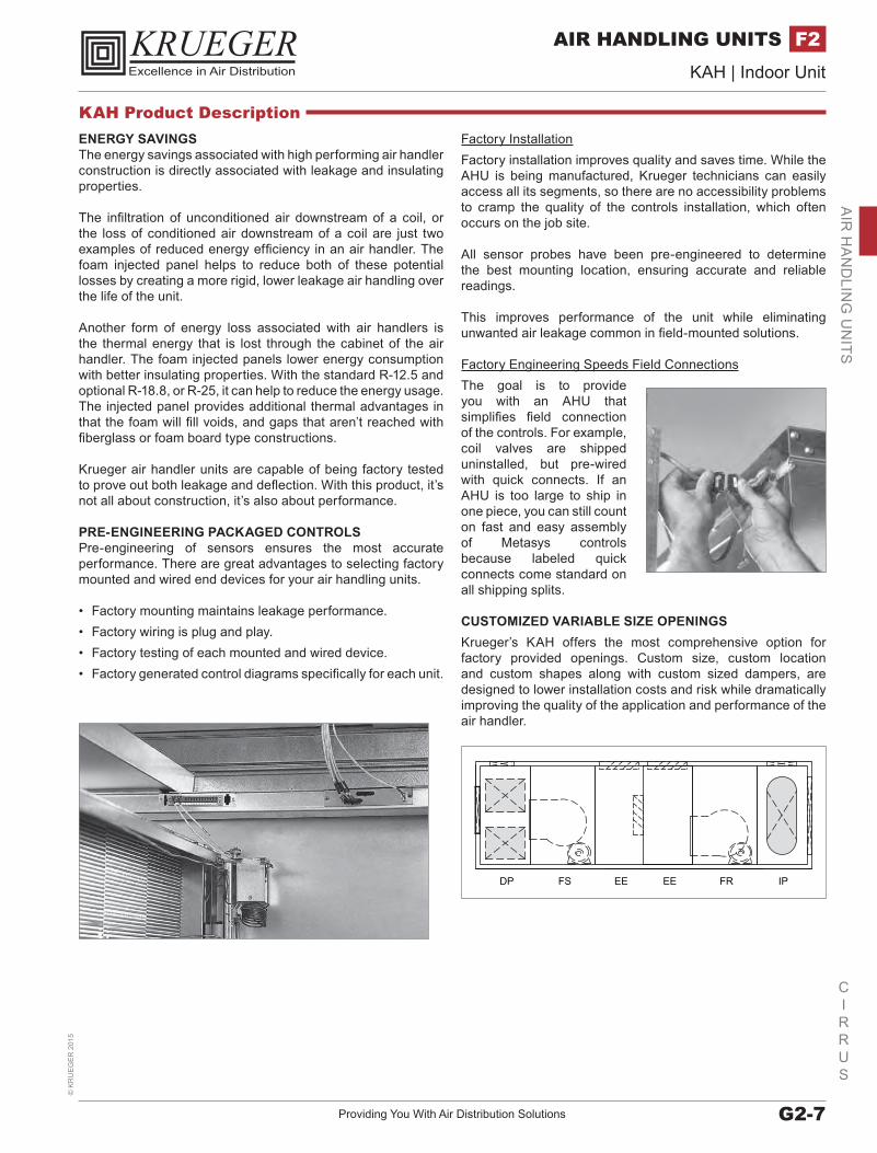
CUSTOMIZED VARIABLE SIZE OPENINGSKrueger’s KAH offers the most comprehensive option for factory provided openings. Custom size, custom location and custom shapes along with custom sized dampers, are designed to lower installation costs and risk while dramatically improving the quality of the application and performance of the air handler.
DP FS EE EE FR IP
KAH Product Description
www.krueger-hvac.com | Excellence in Air DistributionG2-8
CIRRUS
KAH | Indoor Unit©
KR
UE
GE
R 2015
AIR HANDLING UNITSF2A
IR H
AN
DLI
NG
UN
ITS
QUALITY CONSTRUCTION EQUALS IMPROVED IAQQuality construction is a key to a minimum amount of AHU leakage. Leakage is an adversary of indoor air quality. It will depreciate the quality of the supply air by allowing dirty, unfiltered air to seep into the air-stream downstream of the filters.
To prevent this leakage, the rigid, thermally superior panels of the AHUs are matched with a rugged framework to provide an extraordinary casing performance.
The maximum allowable air leakage is less than 1% at +/- 8” w.g. and a maximum L/240 deflection.
The shell of our unit is made up of double wall panels and doors.• Standard liner material is galvanized steel.• Stainless steel liners are optional.• Perforated aluminum liners are optional The floor is a
double wall construction, with a galvanized steel walk-on surface.
• Optional stainless steel.• Optional aluminum tread plate.
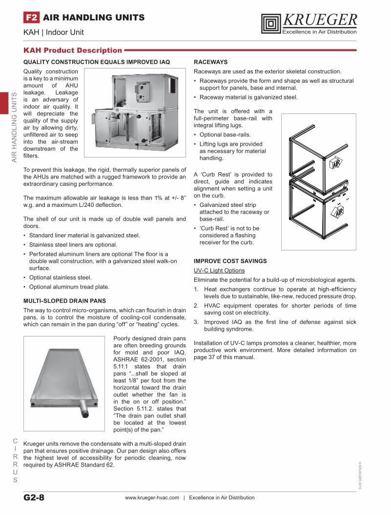
MULTI-SLOPED DRAIN PANSThe way to control micro-organisms, which can flourish in drain pans, is to control the moisture of cooling-coil condensate, which can remain in the pan during “off” or “heating” cycles.
Poorly designed drain pans are often breeding grounds for mold and poor IAQ. ASHRAE 62-2001, section 5.11.1 states that drain pans “...shall be sloped at least 1/8” per foot from the horizontal toward the drain outlet whether the fan is in the on or off position.” Section 5.11.2. states that “The drain pan outlet shall be located at the lowest point(s) of the pan.”
Krueger units remove the condensate with a multi-sloped drain pan that ensures positive drainage. Our pan design also offers the highest level of accessibility for periodic cleaning, now required by ASHRAE Standard 62.
RACEWAYSRaceways are used as the exterior skeletal construction.• Raceways provide the form and shape as well as structural
support for panels, base and internal. • Raceway material is galvanized steel.
The unit is offered with a full-perimeter base-rail with integral lifting lugs.• Optional base-rails.• Lifting lugs are provided
as necessary for material handling.
A ‘Curb Rest’ is provided to direct, guide and indicates alignment when setting a unit on the curb.• Galvanized steel strip
attached to the raceway or base-rail.
• ‘Curb Rest’ is not to be considered a flashing receiver for the curb.
IMPROVE COST SAVINGSUV-C Light OptionsEliminate the potential for a build-up of microbiological agents.1. Heat exchangers continue to operate at high-efficiency
levels due to sustainable, like-new, reduced pressure drop.2. HVAC equipment operates for shorter periods of time
saving cost on electricity.3. Improved IAQ as the first line of defense against sick
building syndrome.
Installation of UV-C lamps promotes a cleaner, healthier, more productive work environment. More detailed information on page 37 of this manual.
KAH Product Description
Providing You With Air Distribution Solutions G2-9
CIRRUS
KAH | Indoor Unit©
KR
UE
GE
R 2
015
AIR HANDLING UNITS F2A
IR H
AN
DLIN
G U
NITS
A COMPLETE LINE OF FILTERSA complete line of clean air solutions for industrial plants, hospitals, schools, pharmaceutical process, airports and commercial buildings are available to control or remove airborne contaminants from the air stream. Achieving acceptable indoor air quality is more involved than calculating and applying the appropriate ventilation rate. Specific AHU performance and other common sense specification items, tied to ASHRAE 62.1 recommendations, can help achieve the healthy indoor air quality environment desired.
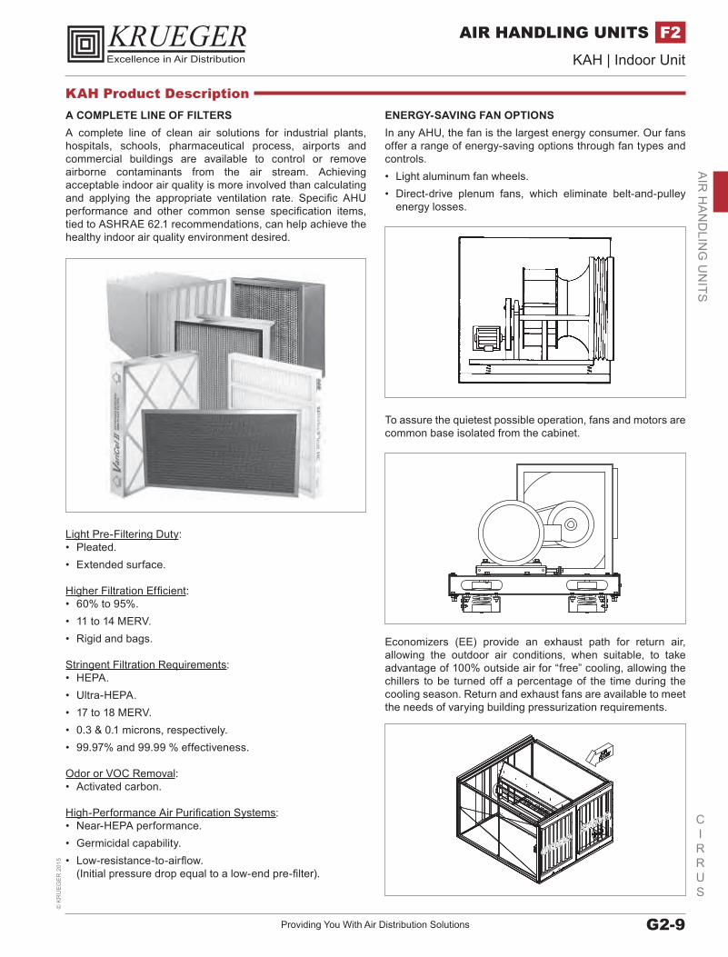
ENERGY-SAVING FAN OPTIONSIn any AHU, the fan is the largest energy consumer. Our fans offer a range of energy-saving options through fan types and controls. • Light aluminum fan wheels.• Direct-drive plenum fans, which eliminate belt-and-pulley
energy losses.
To assure the quietest possible operation, fans and motors are common base isolated from the cabinet.
Economizers (EE) provide an exhaust path for return air, allowing the outdoor air conditions, when suitable, to take advantage of 100% outside air for “free” cooling, allowing the chillers to be turned off a percentage of the time during the cooling season. Return and exhaust fans are available to meet the needs of varying building pressurization requirements.
Light Pre-Filtering Duty:• Pleated.• Extended surface.
Higher Filtration Efficient:• 60% to 95%.• 11 to 14 MERV.• Rigid and bags.
Stringent Filtration Requirements:• HEPA.• Ultra-HEPA.• 17 to 18 MERV.• 0.3 & 0.1 microns, respectively.• 99.97% and 99.99 % effectiveness.
Odor or VOC Removal:• Activated carbon.
High-Performance Air Purification Systems:• Near-HEPA performance.• Germicidal capability.• Low-resistance-to-airflow.
(Initial pressure drop equal to a low-end pre-filter).
KAH Product Description

www.krueger-hvac.com | Excellence in Air DistributionG2-10
CIRRUS
KAH | Indoor Unit©
KR
UE
GE
R 2015
AIR HANDLING UNITSF2A
IR H
AN
DLI
NG
UN
ITS
Energy Saving Air-Modulator™When the air system is designed for variable-air volume (VAV), Krueger offers the most efficient method of VAV fan control with our Air-Modulator™ drive, which is mounted, wired and tested in our factory.
Fans characteristically require much less power as the speed is reduced. With the Air-Modulator™, any reduction in fan speed results in a cubic reduction in fan horsepower. For example, a 10% speed reduction results in a 27% fan horsepower reduction!
Air Modulator Benefits Include:1. Extended Equipment Life – soft start of motor and fan.2. Quieter Fan Operation – fan operating at reduced speed
and constant line of efficiency.3. Eliminates need for motor starter panels.4. Improved system control and response – DDC controls
with LED digital display.5. Proven reliability.
Typically HVAC systems consume a third of the energy used in commercial buildings. Therefore an energy-efficient HVAC system can represent a significant savings in building operating costs. ASHRAE 90.1 provides architects and engineers with guidelines for the design of energy efficient buildings, with the exception of low-rise residential buildings.
FAN APPLICATIONSFan segments are available as supply, return and or exhaust applications. Unit configurations have a segment option of utilizing a single fan or a dual fan arrangement. Isolation consists of 1” or 2” springs with a seismic snubber option. Thrust restraints and OSHA belt guards are available as required.
Double-Width / Double-Inlet (DWDI)• Forward Curve or Airfoil Centrifugal• Belt Driven
Single-Width / Single-Inlet (SWSI)• Airfoil Plenum• Belt Drive or Direct Drive
Bearing Options for Fans with Lubricating Bearings• Extended Lube Line• External Lube Line
KAH Product Description
Providing You With Air Distribution Solutions G2-11
CIRRUS
KAH | Indoor Unit©
KR
UE
GE
R 2
015
AIR HANDLING UNITS F2A
IR H
AN
DLIN
G U
NITS
What little noise is left can be further reduced with direct methods of sound attenuation. Using perforated sound absorbing walls as sound traps in the fan and discharge plenum sections, Krueger equipment engineers can help you design units to meet your critical sound requirements.
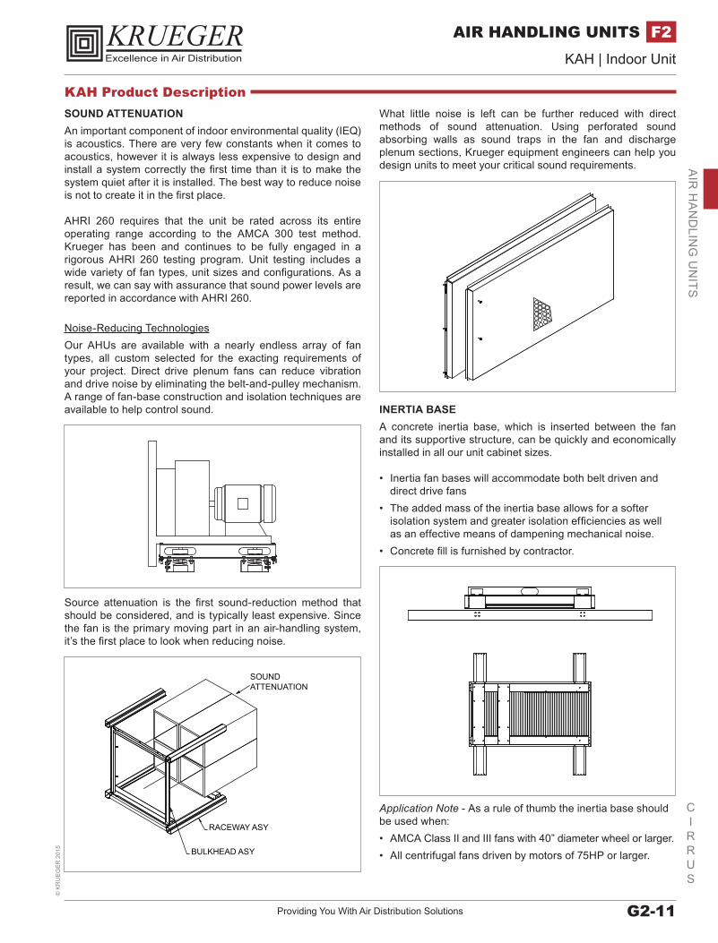
INERTIA BASEA concrete inertia base, which is inserted between the fan and its supportive structure, can be quickly and economically installed in all our unit cabinet sizes.
• Inertia fan bases will accommodate both belt driven and direct drive fans
• The added mass of the inertia base allows for a softer isolation system and greater isolation efficiencies as well as an effective means of dampening mechanical noise.
• Concrete fill is furnished by contractor.
Application Note - As a rule of thumb the inertia base should be used when:• AMCA Class II and III fans with 40” diameter wheel or larger.• All centrifugal fans driven by motors of 75HP or larger.
SOUND ATTENUATIONAn important component of indoor environmental quality (IEQ) is acoustics. There are very few constants when it comes to acoustics, however it is always less expensive to design and install a system correctly the first time than it is to make the system quiet after it is installed. The best way to reduce noise is not to create it in the first place.
AHRI 260 requires that the unit be rated across its entire operating range according to the AMCA 300 test method. Krueger has been and continues to be fully engaged in a rigorous AHRI 260 testing program. Unit testing includes a wide variety of fan types, unit sizes and configurations. As a result, we can say with assurance that sound power levels are reported in accordance with AHRI 260.
Noise-Reducing TechnologiesOur AHUs are available with a nearly endless array of fan types, all custom selected for the exacting requirements of your project. Direct drive plenum fans can reduce vibration and drive noise by eliminating the belt-and-pulley mechanism. A range of fan-base construction and isolation techniques are available to help control sound.
Source attenuation is the first sound-reduction method that should be considered, and is typically least expensive. Since the fan is the primary moving part in an air-handling system, it’s the first place to look when reducing noise.
RACEWAY ASY
BULKHEAD ASY
SOUNDATTENUATION
KAH Product Description
www.krueger-hvac.com | Excellence in Air DistributionG2-12
CIRRUS
KAH | Indoor Unit©
KR
UE
GE
R 2015
AIR HANDLING UNITSF2A
IR H
AN
DLI
NG
UN
ITS
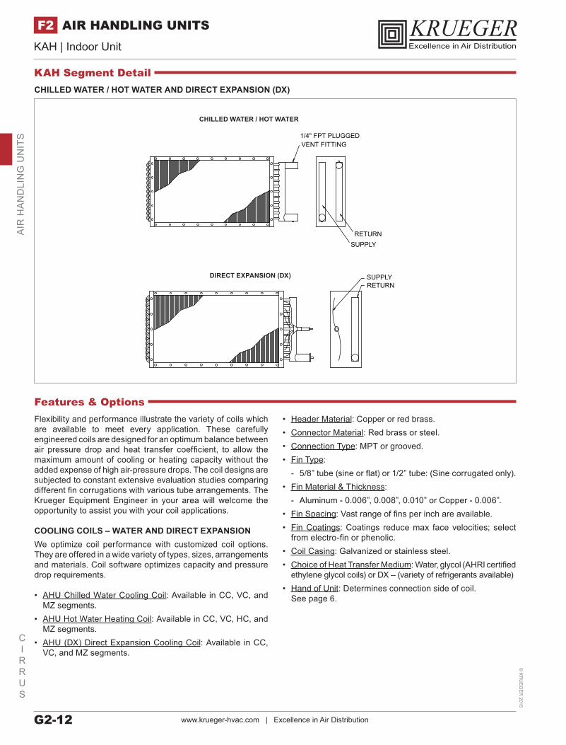
CHILLED WATER / HOT WATER AND DIRECT EXPANSION (DX)
1/4" FPT PLUGGEDVENT FITTING
RETURNSUPPLY
CHILLED WATER / HOT WATER
SUPPLYRETURN
DIRECT EXPANSION (DX)
Flexibility and performance illustrate the variety of coils which are available to meet every application. These carefully engineered coils are designed for an optimum balance between air pressure drop and heat transfer coefficient, to allow the maximum amount of cooling or heating capacity without the added expense of high air-pressure drops. The coil designs are subjected to constant extensive evaluation studies comparing different fin corrugations with various tube arrangements. The Krueger Equipment Engineer in your area will welcome the opportunity to assist you with your coil applications.
COOLING COILS – WATER AND DIRECT EXPANSIONWe optimize coil performance with customized coil options. They are offered in a wide variety of types, sizes, arrangements and materials. Coil software optimizes capacity and pressure drop requirements.
• AHU Chilled Water Cooling Coil: Available in CC, VC, and MZ segments.
• AHU Hot Water Heating Coil: Available in CC, VC, HC, and MZ segments.
• AHU (DX) Direct Expansion Cooling Coil: Available in CC, VC, and MZ segments.
• Header Material: Copper or red brass.• Connector Material: Red brass or steel.• Connection Type: MPT or grooved.• Fin Type:
- 5/8” tube (sine or flat) or 1/2” tube: (Sine corrugated only).• Fin Material & Thickness:
- Aluminum - 0.006”, 0.008”, 0.010” or Copper - 0.006”.• Fin Spacing: Vast range of fins per inch are available.• Fin Coatings: Coatings reduce max face velocities; select
from electro-fin or phenolic.• Coil Casing: Galvanized or stainless steel.• Choice of Heat Transfer Medium: Water, glycol (AHRI certified
ethylene glycol coils) or DX – (variety of refrigerants available)• Hand of Unit: Determines connection side of coil.
See page 6.
Features & Options
KAH Segment Detail
Providing You With Air Distribution Solutions G2-13
CIRRUS
KAH | Indoor Unit©
KR
UE
GE
R 2
015
AIR HANDLING UNITS F2A
IR H
AN
DLIN
G U
NITS
KAH Segment Detail
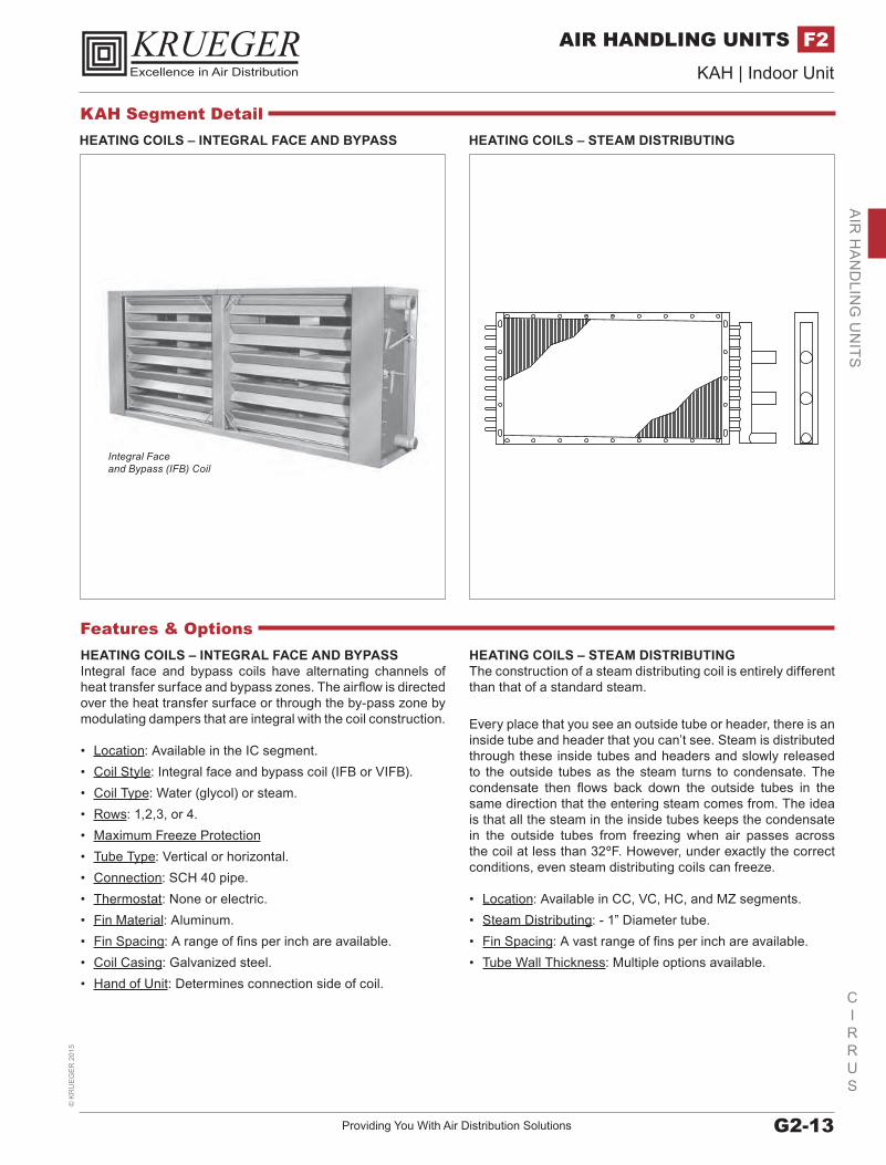
Integral Face and Bypass (IFB) Coil
HEATING COILS – INTEGRAL FACE AND BYPASS
HEATING COILS – INTEGRAL FACE AND BYPASSIntegral face and bypass coils have alternating channels of heat transfer surface and bypass zones. The airflow is directed over the heat transfer surface or through the by-pass zone by modulating dampers that are integral with the coil construction.
• Location: Available in the IC segment. • Coil Style: Integral face and bypass coil (IFB or VIFB).• Coil Type: Water (glycol) or steam.• Rows: 1,2,3, or 4.• Maximum Freeze Protection• Tube Type: Vertical or horizontal.• Connection: SCH 40 pipe.• Thermostat: None or electric.• Fin Material: Aluminum.• Fin Spacing: A range of fins per inch are available.• Coil Casing: Galvanized steel.• Hand of Unit: Determines connection side of coil.
Features & OptionsHEATING COILS – STEAM DISTRIBUTINGThe construction of a steam distributing coil is entirely different than that of a standard steam.
Every place that you see an outside tube or header, there is an inside tube and header that you can’t see. Steam is distributed through these inside tubes and headers and slowly released to the outside tubes as the steam turns to condensate. The condensate then flows back down the outside tubes in the same direction that the entering steam comes from. The idea is that all the steam in the inside tubes keeps the condensate in the outside tubes from freezing when air passes across the coil at less than 32ºF. However, under exactly the correct conditions, even steam distributing coils can freeze.
• Location: Available in CC, VC, HC, and MZ segments.• Steam Distributing: - 1” Diameter tube.• Fin Spacing: A vast range of fins per inch are available.• Tube Wall Thickness: Multiple options available.
HEATING COILS – STEAM DISTRIBUTING
www.krueger-hvac.com | Excellence in Air DistributionG2-14
CIRRUS
KAH | Indoor Unit©
KR
UE
GE
R 2015
AIR HANDLING UNITSF2A
IR H
AN
DLI
NG
UN
ITS
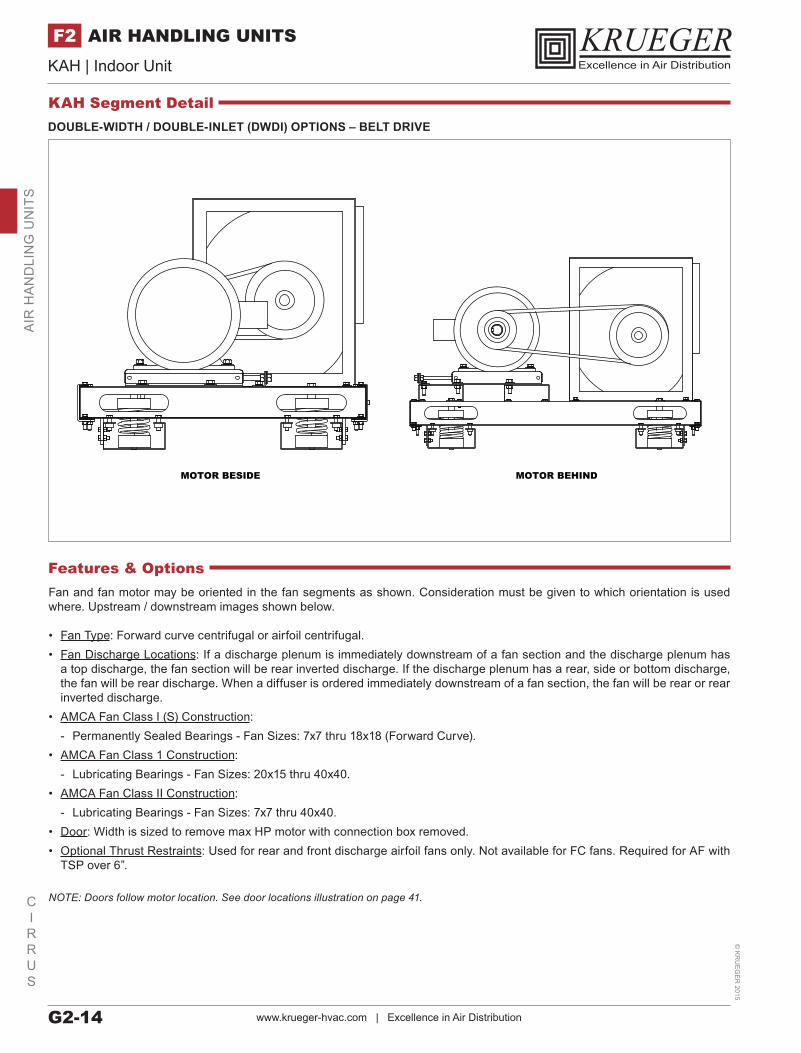
DOUBLE-WIDTH / DOUBLE-INLET (DWDI) OPTIONS – BELT DRIVE
MOTOR BESIDE MOTOR BEHIND
Fan and fan motor may be oriented in the fan segments as shown. Consideration must be given to which orientation is used where. Upstream / downstream images shown below.
• Fan Type: Forward curve centrifugal or airfoil centrifugal.• Fan Discharge Locations: If a discharge plenum is immediately downstream of a fan section and the discharge plenum has
a top discharge, the fan section will be rear inverted discharge. If the discharge plenum has a rear, side or bottom discharge, the fan will be rear discharge. When a diffuser is ordered immediately downstream of a fan section, the fan will be rear or rear inverted discharge.
• AMCA Fan Class I (S) Construction: - Permanently Sealed Bearings - Fan Sizes: 7x7 thru 18x18 (Forward Curve).
• AMCA Fan Class 1 Construction: - Lubricating Bearings - Fan Sizes: 20x15 thru 40x40.
• AMCA Fan Class II Construction: - Lubricating Bearings - Fan Sizes: 7x7 thru 40x40.
• Door: Width is sized to remove max HP motor with connection box removed.• Optional Thrust Restraints: Used for rear and front discharge airfoil fans only. Not available for FC fans. Required for AF with
TSP over 6”.
NOTE: Doors follow motor location. See door locations illustration on page 41.
Features & Options
KAH Segment Detail
Providing You With Air Distribution Solutions G2-15
CIRRUS
KAH | Indoor Unit©
KR
UE
GE
R 2
015
AIR HANDLING UNITS F2A
IR H
AN
DLIN
G U
NITS
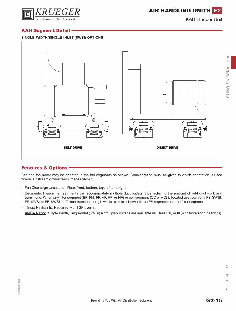
SINGLE-WIDTH/SINGLE-INLET (SWSI) OPTIONS
BELT DRIVE DIRECT DRIVE
Fan and fan motor may be oriented in the fan segments as shown. Consideration must be given to which orientation is used where. Upstream/downstream images shown.
• Fan Discharge Locations - Rear, front, bottom, top, left and right.• Segments: Plenum fan segments can accommodate multiple duct outlets, thus reducing the amount of field duct work and
transitions. When any filter segment (EF, FM, FF, AF, RF, or HF) or coil segment (CC or HC) is located upstream of a FS-SWSI, FR-SWSI or FE-SWSI, sufficient transition length will be required between the FS segment and the filter segment.
• Thrust Restraints: Required with TSP over 3”.• AMCA Rating: Single Width, Single-Inlet (SWSI) air foil plenum fans are available as Class I, II, or III (with lubricating bearings).
Features & Options
KAH Segment Detail
www.krueger-hvac.com | Excellence in Air DistributionG2-16
CIRRUS
KAH | Indoor Unit©
KR
UE
GE
R 2015
AIR HANDLING UNITSF2A
IR H
AN
DLI
NG
UN
ITS
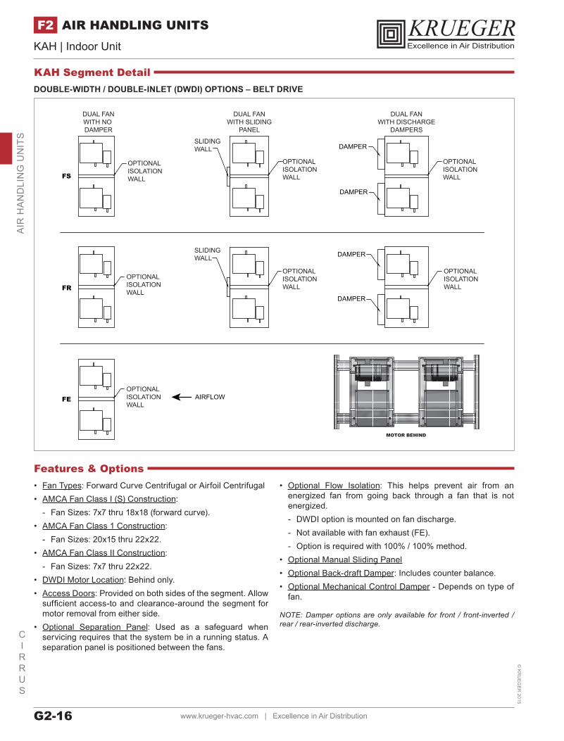
DOUBLE-WIDTH / DOUBLE-INLET (DWDI) OPTIONS – BELT DRIVE
FS
FR
FE
DAMPER
DAMPER
DAMPER
DAMPER
DUAL FANWITH NO DAMPER
DUAL FANWITH SLIDING
PANEL
DUAL FANWITH DISCHARGE
DAMPERS
OPTIONALISOLATIONWALL
OPTIONALISOLATIONWALL
OPTIONALISOLATIONWALL
OPTIONALISOLATIONWALL
OPTIONALISOLATIONWALL
OPTIONALISOLATIONWALL
SLIDINGWALL
SLIDINGWALL
OPTIONALISOLATIONWALL
AIRFLOW
• Fan Types: Forward Curve Centrifugal or Airfoil Centrifugal• AMCA Fan Class I (S) Construction:
- Fan Sizes: 7x7 thru 18x18 (forward curve).• AMCA Fan Class 1 Construction:
- Fan Sizes: 20x15 thru 22x22.• AMCA Fan Class II Construction:
- Fan Sizes: 7x7 thru 22x22.• DWDI Motor Location: Behind only.• Access Doors: Provided on both sides of the segment. Allow
sufficient access-to and clearance-around the segment for motor removal from either side.
• Optional Separation Panel: Used as a safeguard when servicing requires that the system be in a running status. A separation panel is positioned between the fans.
• Optional Flow Isolation: This helps prevent air from an energized fan from going back through a fan that is not energized. - DWDI option is mounted on fan discharge. - Not available with fan exhaust (FE). - Option is required with 100% / 100% method.
• Optional Manual Sliding Panel• Optional Back-draft Damper: Includes counter balance.• Optional Mechanical Control Damper - Depends on type of
fan.
NOTE: Damper options are only available for front / front-inverted / rear / rear-inverted discharge.
Features & Options
MOTOR BEHIND
KAH Segment Detail
Providing You With Air Distribution Solutions G2-17
CIRRUS
KAH | Indoor Unit©
KR
UE
GE
R 2
015
AIR HANDLING UNITS F2A
IR H
AN
DLIN
G U
NITS
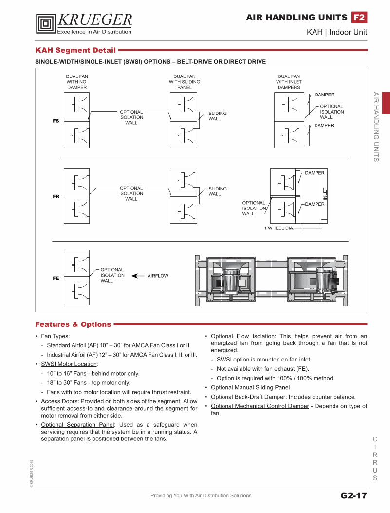
SINGLE-WIDTH/SINGLE-INLET (SWSI) OPTIONS – BELT-DRIVE OR DIRECT DRIVE
FS
FR
DAMPER
DAMPER
FE
INLE
T
DAMPER
DAMPER
1 WHEEL DIA.
DUAL FANWITH NO DAMPER
DUAL FANWITH SLIDING
PANEL
DUAL FANWITH INLETDAMPERS
OPTIONALISOLATIONWALL
OPTIONALISOLATIONWALL
OPTIONALISOLATIONWALL
OPTIONALISOLATION
WALL
OPTIONALISOLATION
WALL
SLIDINGWALL
SLIDINGWALL
AIRFLOW
• Fan Types: - Standard Airfoil (AF) 10” – 30” for AMCA Fan Class I or II. - Industrial Airfoil (AF) 12” – 30” for AMCA Fan Class I, II, or III.
• SWSI Motor Location: - 10” to 16” Fans - behind motor only. - 18” to 30” Fans - top motor only. - Fans with top motor location will require thrust restraint.
• Access Doors: Provided on both sides of the segment. Allow sufficient access-to and clearance-around the segment for motor removal from either side.
• Optional Separation Panel: Used as a safeguard when servicing requires that the system be in a running status. A separation panel is positioned between the fans.
• Optional Flow Isolation: This helps prevent air from an energized fan from going back through a fan that is not energized. - SWSI option is mounted on fan inlet. - Not available with fan exhaust (FE). - Option is required with 100% / 100% method.
• Optional Manual Sliding Panel• Optional Back-Draft Damper: Includes counter balance.• Optional Mechanical Control Damper - Depends on type of
fan.
Features & Options
KAH Segment Detail

www.krueger-hvac.com | Excellence in Air DistributionG2-18
CIRRUS
KAH | Indoor Unit©
KR
UE
GE
R 2015
AIR HANDLING UNITSF2A
IR H
AN
DLI
NG
UN
ITS
COOLING COIL – (CC)
COOLING COIL – (CC)When cooling 100% OA, there are precautions required. Summer design conditions are such that when air is cooled down to normal coil leaving temperatures, there is a considerable amount of condensate generated.
Many applications suggest cooling coils should be selected for an air velocity under 500 FPM. If the unit is selected as a 100% OA application, the drainage area for larger face area coils will be increased to properly compensate for the probable condensate.
• Coils: A combination of water and DX coils in the same segment requires all coils to be of the same tube diameter. Multiple water coils configured in the same segment must be of the same tube diameter. Steam coils may be configured with 5/8” tube coils. A spacer must be used between a steam coil and any water coil or DX coil.
• Headers: Usual header location is drive side. All headers in the same segment must exit the unit on the same side.
• Door: Usual door location is drive side. With pipe chase, the door is always opposite the pipe chase.
• Drain Pan Material: Liner is galvanized or stainless steel.
Features & Options
HEATING COIL – (HC)
HEATING COIL – (HC)When heating only is required the heating coil segment is an excellent minimally sized housing which shall accommodate a single heating coil. Coils are offered with left or right hand connections. Coils will be individually mounted and easily removable.
Coil segment panels (side panels and top panel) shall be easily removable to allow for removal and replacement of coils, without affecting the structural integrity of the unit.
• Coils: Only hot water and steam coils are available in the HC segment. Only one coil (hot water or steam) is permitted per segment.
• Headers: Usual header location is on the drive side.• Doors: Not available.• Optional Drain Pan: Usual drain location is header side. The
drain is always opposite the pipe chase.
KAH Segment Detail
Providing You With Air Distribution Solutions G2-19
CIRRUS
KAH | Indoor Unit©
KR
UE
GE
R 2
015
AIR HANDLING UNITS F2A
IR H
AN
DLIN
G U
NITS
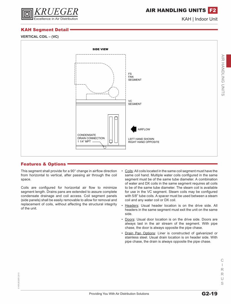
VERTICAL COIL – (VC)
RIGHT HAND OPPOSITELEFT HAND SHOWN
AIRFLOW
CONDENSATE DRAIN CONNECTION1 1/4” MPT
SIDE VIEW
FSFANSEGMENT
VCSEGMENT
This segment shall provide for a 90° change in airflow direction from horizontal to vertical, after passing air through the coil space.
Coils are configured for horizontal air flow to minimize segment length. Drains pans are extended to assure complete condensate drainage and coil access. Coil segment panels (side panels) shall be easily removable to allow for removal and replacement of coils, without affecting the structural integrity of the unit.
• Coils: All coils located in the same coil segment must have the same coil hand. Multiple water coils configured in the same segment must be of the same tube diameter. A combination of water and DX coils in the same segment requires all coils to be of the same tube diameter. The steam coil is available for use in the VC segment. Steam coils may be configured with 5/8” tube coils. A spacer must be used between a steam coil and any water coil or DX coil.
• Headers: Usual header location is on the drive side. All headers in the same segment must exit the unit on the same side.
• Doors: Usual door location is on the drive side. Doors are always last in the air stream of the segment. With pipe chase, the door is always opposite the pipe chase.
• Drain Pan Options: Liner is constructed of galvanized or stainless steel. Usual drain location is on header side. With pipe chase, the drain is always opposite the pipe chase.
Features & Options
KAH Segment Detail

www.krueger-hvac.com | Excellence in Air DistributionG2-20
CIRRUS
KAH | Indoor Unit©
KR
UE
GE
R 2015
AIR HANDLING UNITSF2A
IR H
AN
DLI
NG
UN
ITS
ANGLE WALL DESIGNAvailable in both heating and cooling coil segments, this staggered coil design increases coil face area and allows increased CFM without having to increase cabinet size.
• Coils: A staggered coil can not be combined with a non-staggered coil in the same segment. Each coil bank will be located over a drain pan. Not available as a reduced face coil option.
• Drain Pan: The drain pan connection hand follows coil hand. If coil connections are on both sides, the drain pan connection follows the ”primary” side of the unit.
• Headers: Coil connections can be on the same side or opposite sides. Optional factory extended piping connections for each coil to the exterior of the unit. Optional insulation for extended piping. Extended piping does not apply to DX coils.
• Optional Controls: Optional control valve and valve jack (manifolded together, external of unit).
BACK-TO-BACK DESIGNAvailable in both heating and cooling coil segments, this staggered coil design is specifically for a reduced coil pull distance and for opposite side connections. Two shorter coils will be used in place of one longer coil.
• Coils: A staggered coil can not be combined with a non-staggered coil in the same segment. Not available as a reduced face coil option.
• Drain Pan: The drain pan connection follows the ”primary” side of the unit.
• Headers: Coil connections can be on the same side or opposite sides.
Features & Options
ANGLE WALL DESIGN BACK-TO-BACK DESIGN
KAH Segment Detail

Providing You With Air Distribution Solutions G2-21
CIRRUS
KAH | Indoor Unit©
KR
UE
GE
R 2
015
AIR HANDLING UNITS F2A
IR H
AN
DLIN
G U
NITS
MULTI-ZONE SEGMENT – (MZ)
HOT DECK
HOT DECKDAMPER(FULL) WIDTH
DWDI- OR - SWSI
CC(COLD DECK) XA
AIRFLOWDI
COLD DECKDAMPER(FULL) WIDTH
MZ heating and air conditioning units offer design and application advantages over various smaller single zone units. MZ and dual deck air-handling units can be configured for heating and cooling, or cooling and ventilation, or ventilation and heating applications.
• Location: The MZ segment will be the last segment in air-stream.• Air Pressure Drop Balance Plates: Used to equalize pressure drop across the hot and cold deck coils when required.• Discharge Options: Top or rear, with or without damper.• Discharge Configurations: The bottom tier is the cold deck and contains a diffuser and a cooling coil space. The top tier is the
hot deck and contains a heating coil mounted horizontally at the upstream side of the hot deck.• Air-Stream Path: Air enters the diffuser then splits into two streams. One stream turns up through the hot deck coil and exits
the rear or top through the hot deck damper. The other stream continues horizontally through the cooling coil and exits the rear or top through the cold deck damper.
• Optional Door: Used for cold deck.• Optional Less Zone Damper: The MZ unit is (optionally) available less the zone damper for use on dual duct or other blow-thru
systems. If a hot deck opening is not required, it may be blanked-off in the field.
Features & Options
KAH Segment Detail
www.krueger-hvac.com | Excellence in Air DistributionG2-22
CIRRUS
KAH | Indoor Unit©
KR
UE
GE
R 2015
AIR HANDLING UNITSF2A
IR H
AN
DLI
NG
UN
ITS
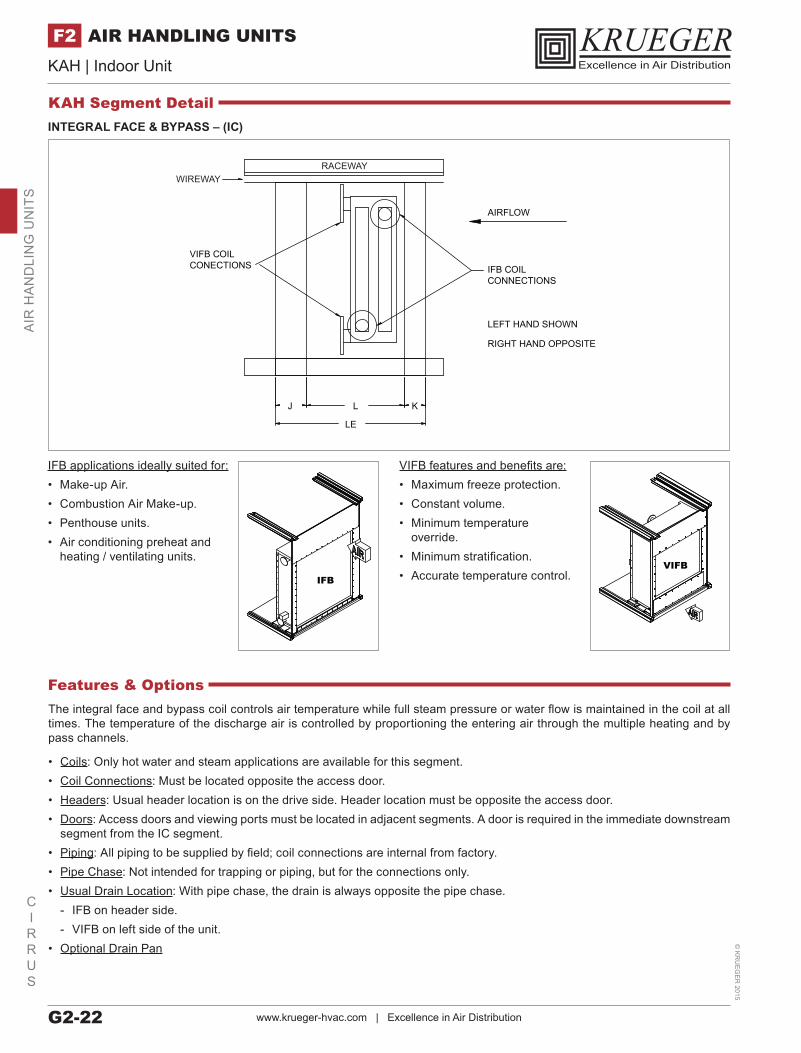
INTEGRAL FACE & BYPASS – (IC)
RIGHT HAND OPPOSITE
LEFT HAND SHOWN
AIRFLOW
L
LE
J K
VIFB COILCONECTIONS IFB COIL
CONNECTIONS
RACEWAYWIREWAY
IFB applications ideally suited for:• Make-up Air.• Combustion Air Make-up.• Penthouse units.• Air conditioning preheat and
heating / ventilating units.
IFB
VIFB features and benefits are:• Maximum freeze protection.• Constant volume.• Minimum temperature
override.• Minimum stratification.• Accurate temperature control.
VIFB
The integral face and bypass coil controls air temperature while full steam pressure or water flow is maintained in the coil at all times. The temperature of the discharge air is controlled by proportioning the entering air through the multiple heating and by pass channels.
• Coils: Only hot water and steam applications are available for this segment.• Coil Connections: Must be located opposite the access door.• Headers: Usual header location is on the drive side. Header location must be opposite the access door.• Doors: Access doors and viewing ports must be located in adjacent segments. A door is required in the immediate downstream
segment from the IC segment.• Piping: All piping to be supplied by field; coil connections are internal from factory. • Pipe Chase: Not intended for trapping or piping, but for the connections only.• Usual Drain Location: With pipe chase, the drain is always opposite the pipe chase.
- IFB on header side. - VIFB on left side of the unit.
• Optional Drain Pan
Features & Options
KAH Segment Detail
Providing You With Air Distribution Solutions G2-23
CIRRUS
KAH | Indoor Unit©
KR
UE
GE
R 2
015
AIR HANDLING UNITS F2A
IR H
AN
DLIN
G U
NITS
I.D. FAN
CONTROLPANEL
DOOR
HEAT EX.
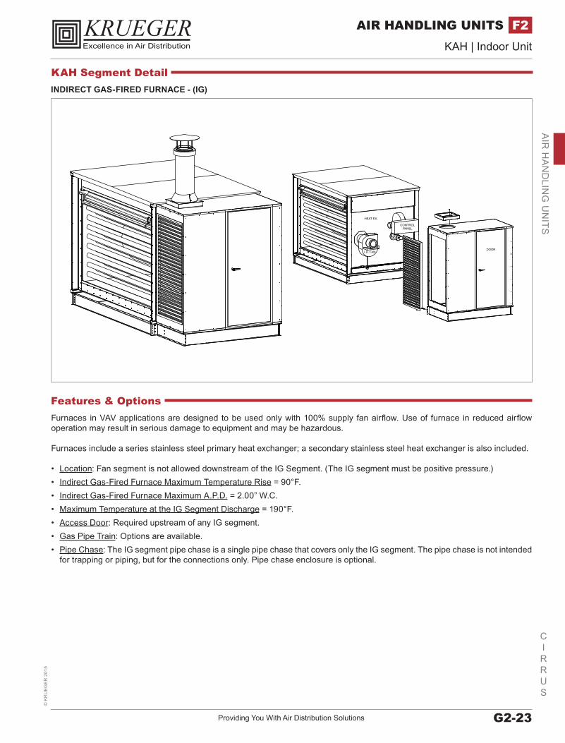
INDIRECT GAS-FIRED FURNACE - (IG)
Furnaces in VAV applications are designed to be used only with 100% supply fan airflow. Use of furnace in reduced airflow operation may result in serious damage to equipment and may be hazardous.
Furnaces include a series stainless steel primary heat exchanger; a secondary stainless steel heat exchanger is also included.
• Location: Fan segment is not allowed downstream of the IG Segment. (The IG segment must be positive pressure.)• Indirect Gas-Fired Furnace Maximum Temperature Rise = 90°F.• Indirect Gas-Fired Furnace Maximum A.P.D. = 2.00” W.C.• Maximum Temperature at the IG Segment Discharge = 190°F.• Access Door: Required upstream of any IG segment.• Gas Pipe Train: Options are available.• Pipe Chase: The IG segment pipe chase is a single pipe chase that covers only the IG segment. The pipe chase is not intended
for trapping or piping, but for the connections only. Pipe chase enclosure is optional.
Features & Options
KAH Segment Detail

www.krueger-hvac.com | Excellence in Air DistributionG2-24
CIRRUS
KAH | Indoor Unit©
KR
UE
GE
R 2015
AIR HANDLING UNITSF2A
IR H
AN
DLI
NG
UN
ITS
ELECTRIC HEAT – (EH)
• Arrangements: The EH segment can be installed in either draw-through or blow-through arrangements.• Coil Construction: “Open Coil” construction with 80% nickel, 20% chromium coil elements machine crimped to stainless steel
terminals and amply supported on ceramic bushing isolators. Open coil heaters are furnished with a disk-type, automatic reset thermal cutout for primary over-temperature protection. Heaters are also furnished with disk-type, load-carrying manual reset thermal cutouts, factory wired in series with heater stages for secondary protection.
• Heaters: - Rated for the voltage, phase, and number of heating stages indicated in the schedule. All three-phase heaters will have
equal, balanced, three-phase stages. - Heaters shall be furnished with built-in fuses per NEC. Heaters with loads greater than 48 amps will be furnished with built-
in fusing. Heaters shall be sub-circuited into a maximum of 48 amps per circuit. Low resistance single element fuses will be mounted in phenolic fuse blocks fitted with extra tension springs to assure cool connections. Fuses shall be sized at least 125% of the load.
• Remote Mounted Terminal Panels: An electric heat control panel may be selected as a remote panel. In this case, the panel will be shipped separate to the customer for field installation.
• Internal Wiring: Stranded copper with 105°C minimum insulation and shall be terminated in crimped connectors or box lugs.• Power and Control Terminal Blocks: Provided and clearly marked for all field wiring and shall be sized for installation of 75°C
copper wire rated in accordance with NEC Table 310-16, not more than three conductors in a conduit.• Optional Finned Tubular Construction• Optional Wide Access Door: Ordered on the opposite side of the electric heater control panel.• Optional SCR Controller: Available on all heaters with a height dimension greater than 26.5”. Delta T = (kW * 3160) / CFM
Features & Options
KAH Segment Detail
Providing You With Air Distribution Solutions G2-25
CIRRUS
KAH | Indoor Unit©
KR
UE
GE
R 2
015
AIR HANDLING UNITS F2A
IR H
AN
DLIN
G U
NITS
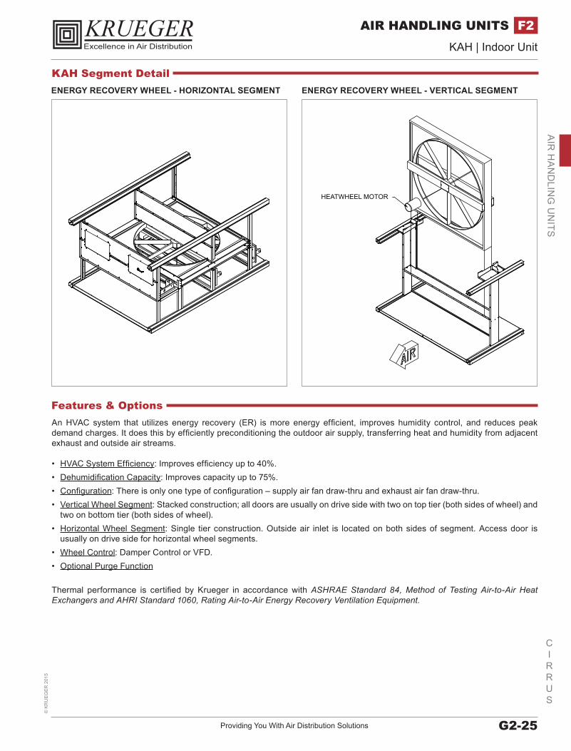
ENERGY RECOVERY WHEEL - HORIZONTAL SEGMENT ENERGY RECOVERY WHEEL - VERTICAL SEGMENT
HEATWHEEL MOTOR
An HVAC system that utilizes energy recovery (ER) is more energy efficient, improves humidity control, and reduces peak demand charges. It does this by efficiently preconditioning the outdoor air supply, transferring heat and humidity from adjacent exhaust and outside air streams.
• HVAC System Efficiency: Improves efficiency up to 40%.• Dehumidification Capacity: Improves capacity up to 75%.• Configuration: There is only one type of configuration – supply air fan draw-thru and exhaust air fan draw-thru.• Vertical Wheel Segment: Stacked construction; all doors are usually on drive side with two on top tier (both sides of wheel) and
two on bottom tier (both sides of wheel).• Horizontal Wheel Segment: Single tier construction. Outside air inlet is located on both sides of segment. Access door is
usually on drive side for horizontal wheel segments.• Wheel Control: Damper Control or VFD.• Optional Purge Function
Thermal performance is certified by Krueger in accordance with ASHRAE Standard 84, Method of Testing Air-to-Air Heat Exchangers and AHRI Standard 1060, Rating Air-to-Air Energy Recovery Ventilation Equipment.
Features & Options
KAH Segment Detail

www.krueger-hvac.com | Excellence in Air DistributionG2-26
CIRRUS
KAH | Indoor Unit©
KR
UE
GE
R 2015
AIR HANDLING UNITSF2A
IR H
AN
DLI
NG
UN
ITS
MIXING BOX / MIXING SEGMENT (MB/FM)
FRONT DAMPER
TOP DAMPER
END WALL PANEL
ROOF PANEL
Krueger mixing box (MB) combines fresh air and re-circulated air by means of interconnected dampers. A space-saving combination filter mixing segment (FM) offers an angle filter as an integral part of the mixing segment to economically provide filtering and mixing capabilities.
• Location: Typically, it must be the first segment in direction of airflow.• Optional Access Doors: Used for the mixing box (MB) segment, but a combination filter mixing segment (FM) will provide a
full-height access door for filter service as standard.• Optional Drain Pan: Not available when bottom opening is selected.• Optional Openings / Dampers: Variable size openings and dampers are available.• Optional Safety Grate: Used for bottom openings.
Features & Options
KAH Segment Detail

Providing You With Air Distribution Solutions G2-27
CIRRUS
KAH | Indoor Unit©
KR
UE
GE
R 2
015
AIR HANDLING UNITS F2A
IR H
AN
DLIN
G U
NITS
ECONOMIZER
ANGLE FILTER ASSEMBLY
ECONOMIZER WALL
DAMPER
DOOR
DOOR
DAMPER
Krueger offers numerous economizer configurations for various ventilation applications, with factory packaged controls in-mind.
Correctly set-up economizers will constantly track building pressurization, as well as both indoor and outdoor air temperatures using transducers, mixed air sensors, and enthalpy control that monitors air temperature and humidity.
• Location: The EE or EF segment may be first in the air-stream or may be used in conjunction with other segments in an economizer application.
Features & Options
KAH Segment Detail

www.krueger-hvac.com | Excellence in Air DistributionG2-28
CIRRUS
KAH | Indoor Unit©
KR
UE
GE
R 2015
AIR HANDLING UNITSF2A
IR H
AN
DLI
NG
UN
ITS
ECONOMIZER ARRANGEMENTS
TOPVIEW
SIDEVIEW
L/R SIDEDAMPER
ANGLEDMIXINGDAMPER
EE - Economizer withangled mixing damper.
EE - Economizer with verticalmixing damper.
EF - Filter/Economizer
(100% OA, 100% EA)
EE - Inlet/Economizer(50% OA on each side with barometric exhaust)
VE - Vertical Economizer
TOPVIEW
SIDEVIEW
SIDEVIEW
NOTE: VF (VerticalFilter Economizer) is available with filtration.
METHODS OF PRESSURIZATION CONTROLBuilding pressurization provides insight in identifying, diagnosing, correcting and most importantly, avoiding some unusual building operational problems.
• Full Return Air Fan Economizer: Pressure losses will be handled through the return air system and exhaust dampers. The supply fan will handle pressure losses through the outside air dampers and mixed air dampers.
• Dedicated Exhaust Fan Economizer: The fan runs only when economizer opens the OA dampers. Pressure losses are handled through return air system when in exhaust mode or the exhaust air path.
Features & Options
KAH Segment Detail
Providing You With Air Distribution Solutions G2-29
CIRRUS
KAH | Indoor Unit©
KR
UE
GE
R 2
015
AIR HANDLING UNITS F2A
IR H
AN
DLIN
G U
NITS
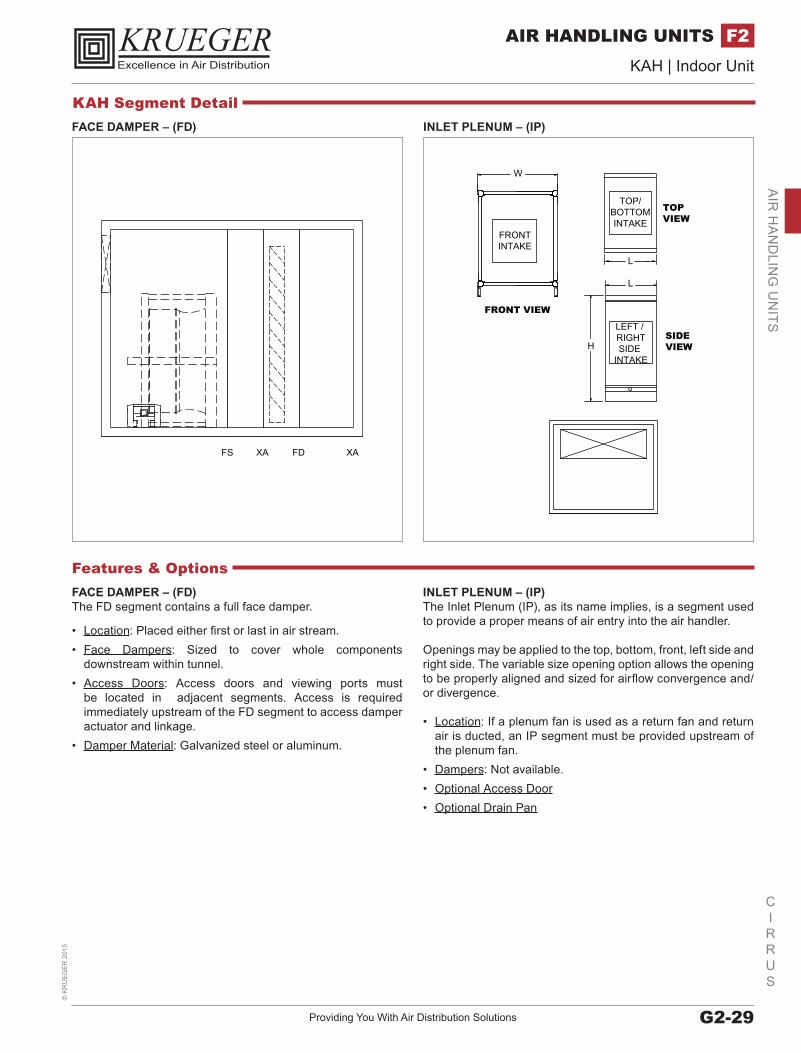
FACE DAMPER – (FD)
FS XA FD XA
INLET PLENUM – (IP)The Inlet Plenum (IP), as its name implies, is a segment used to provide a proper means of air entry into the air handler.
Openings may be applied to the top, bottom, front, left side and right side. The variable size opening option allows the opening to be properly aligned and sized for airflow convergence and/or divergence.
• Location: If a plenum fan is used as a return fan and return air is ducted, an IP segment must be provided upstream of the plenum fan.
• Dampers: Not available.• Optional Access Door• Optional Drain Pan
FACE DAMPER – (FD)The FD segment contains a full face damper.
• Location: Placed either first or last in air stream.• Face Dampers: Sized to cover whole components
downstream within tunnel.• Access Doors: Access doors and viewing ports must
be located in adjacent segments. Access is required immediately upstream of the FD segment to access damper actuator and linkage.
• Damper Material: Galvanized steel or aluminum.
Features & Options
W
H
FRONTINTAKE
FRONT VIEW
SIDEVIEW
TOP/BOTTOMINTAKE
L
L
TOPVIEW
LEFT / RIGHTSIDE
INTAKE
INLET PLENUM – (IP)
KAH Segment Detail
www.krueger-hvac.com | Excellence in Air DistributionG2-30
CIRRUS
KAH | Indoor Unit©
KR
UE
GE
R 2015
AIR HANDLING UNITSF2A
IR H
AN
DLI
NG
UN
ITS
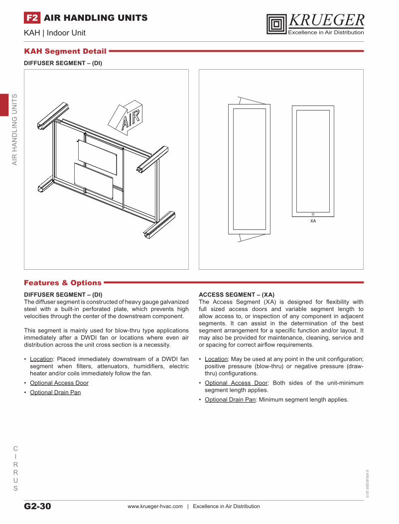
DIFFUSER SEGMENT – (DI)
DIFFUSER SEGMENT – (DI)The diffuser segment is constructed of heavy gauge galvanized steel with a built-in perforated plate, which prevents high velocities through the center of the downstream component.
This segment is mainly used for blow-thru type applications immediately after a DWDI fan or locations where even air distribution across the unit cross section is a necessity.
• Location: Placed immediately downstream of a DWDI fan segment when filters, attenuators, humidifiers, electric heater and/or coils immediately follow the fan.
• Optional Access Door• Optional Drain Pan
ACCESS SEGMENT – (XA)The Access Segment (XA) is designed for flexibility with full sized access doors and variable segment length to allow access to, or inspection of any component in adjacent segments. It can assist in the determination of the best segment arrangement for a specific function and/or layout. It may also be provided for maintenance, cleaning, service and or spacing for correct airflow requirements.
• Location: May be used at any point in the unit configuration; positive pressure (blow-thru) or negative pressure (draw-thru) configurations.
• Optional Access Door: Both sides of the unit-minimum segment length applies.
• Optional Drain Pan: Minimum segment length applies.
Features & Options
XA
KAH Segment Detail
Providing You With Air Distribution Solutions G2-31
CIRRUS
KAH | Indoor Unit©
KR
UE
GE
R 2
015
AIR HANDLING UNITS F2A
IR H
AN
DLIN
G U
NITS
FS XA AF
DP FS XA AF
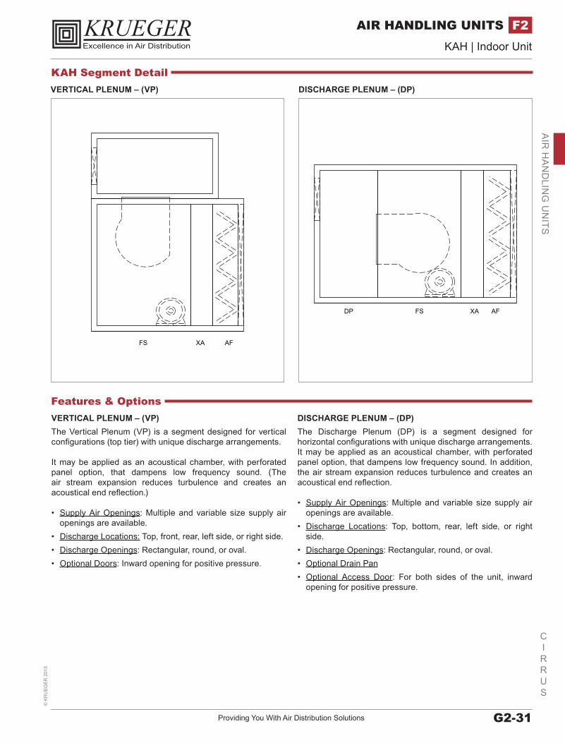
VERTICAL PLENUM – (VP)The Vertical Plenum (VP) is a segment designed for vertical configurations (top tier) with unique discharge arrangements.
It may be applied as an acoustical chamber, with perforated panel option, that dampens low frequency sound. (The air stream expansion reduces turbulence and creates an acoustical end reflection.)
• Supply Air Openings: Multiple and variable size supply air openings are available.
• Discharge Locations: Top, front, rear, left side, or right side.• Discharge Openings: Rectangular, round, or oval.• Optional Doors: Inward opening for positive pressure.
DISCHARGE PLENUM – (DP)The Discharge Plenum (DP) is a segment designed for horizontal configurations with unique discharge arrangements. It may be applied as an acoustical chamber, with perforated panel option, that dampens low frequency sound. In addition, the air stream expansion reduces turbulence and creates an acoustical end reflection.
• Supply Air Openings: Multiple and variable size supply air openings are available.
• Discharge Locations: Top, bottom, rear, left side, or right side.
• Discharge Openings: Rectangular, round, or oval.• Optional Drain Pan• Optional Access Door: For both sides of the unit, inward
opening for positive pressure.
Features & Options
VERTICAL PLENUM – (VP) DISCHARGE PLENUM – (DP)
KAH Segment Detail
www.krueger-hvac.com | Excellence in Air DistributionG2-32
CIRRUS
KAH | Indoor Unit©
KR
UE
GE
R 2015
AIR HANDLING UNITSF2A
IR H
AN
DLI
NG
UN
ITS
RACEWAY ASSEMBLY
SOUNDATTENUATOR
BULKHEAD ASSEMBLY
FORWARD FLOW REVERSE FLOW
UNDER FORWARD FLOW CONDITIONS,HIGH FREQUENCY SOUND IS REFRACTEDINTO THE DUCT-SILENCER WALLS.
UNDER REVERSE FLOW CONDITIONS,SOUND IS REFRACTED AWAY FROM THEWALLS AND TOWARD THE CENTEROF THE DUCT-SILENCER.
FORWARD FLOW REVERSE FLOW
UNDER FORWARD FLOW CONDITIONS,HIGH FREQUENCY SOUND IS REFRACTEDINTO THE DUCT-SILENCER WALLS.
UNDER REVERSE FLOW CONDITIONS,SOUND IS REFRACTED AWAY FROM THEWALLS AND TOWARD THE CENTEROF THE DUCT-SILENCER.
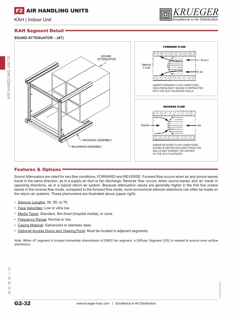
SOUND ATTENUATOR – (AT)
Sound Attenuators are rated for two flow conditions, FORWARD and REVERSE. Forward flow occurs when air and sound-waves travel in the same direction, as in a supply air duct or fan discharge. Reverse flow occurs when sound-waves and air travel in opposing directions, as in a typical return-air system. Because attenuation values are generally higher in the first five octave bands in the reverse flow mode, compared to the forward flow mode, more economical silencer selections can often be made on the return-air systems. These phenomena are illustrated above (upper right).
• Silencer Lengths: 3ft, 5ft, or 7ft.• Face Velocities: Low or ultra low.• Media Types: Standard, film-lined (hospital media), or none.• Frequency Range: Normal or low.• Casing Material: Galvanized or stainless steel.• Optional Access Doors and Viewing Ports: Must be located in adjacent segments.
Note: When AT segment is located immediate downstream of DWDI fan segment, a Diffuser Segment (DS) is needed to ensure even airflow distribution.
Features & Options
KAH Segment Detail
Providing You With Air Distribution Solutions G2-33
CIRRUS
KAH | Indoor Unit©
KR
UE
GE
R 2
015
AIR HANDLING UNITS F2A
IR H
AN
DLIN
G U
NITS
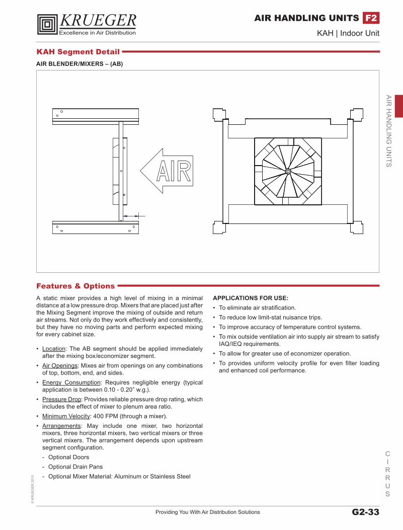
AIR BLENDER/MIXERS – (AB)
A static mixer provides a high level of mixing in a minimal distance at a low pressure drop. Mixers that are placed just after the Mixing Segment improve the mixing of outside and return air streams. Not only do they work effectively and consistently, but they have no moving parts and perform expected mixing for every cabinet size.
• Location: The AB segment should be applied immediately after the mixing box/economizer segment.
• Air Openings: Mixes air from openings on any combinations of top, bottom, end, and sides.
• Energy Consumption: Requires negligible energy (typical application is between 0.10 - 0.20” w.g.).
• Pressure Drop: Provides reliable pressure drop rating, which includes the effect of mixer to plenum area ratio.
• Minimum Velocity: 400 FPM (through a mixer).• Arrangements: May include one mixer, two horizontal
mixers, three horizontal mixers, two vertical mixers or three vertical mixers. The arrangement depends upon upstream segment configuration. - Optional Doors - Optional Drain Pans - Optional Mixer Material: Aluminum or Stainless Steel
APPLICATIONS FOR USE:• To eliminate air stratification.• To reduce low limit-stat nuisance trips.• To improve accuracy of temperature control systems.• To mix outside ventilation air into supply air stream to satisfy
IAQ/IEQ requirements.• To allow for greater use of economizer operation.• To provides uniform velocity profile for even filter loading
and enhanced coil performance.
Features & Options
KAH Segment Detail
www.krueger-hvac.com | Excellence in Air DistributionG2-34
CIRRUS
KAH | Indoor Unit©
KR
UE
GE
R 2015
AIR HANDLING UNITSF2A
IR H
AN
DLI
NG
UN
ITS
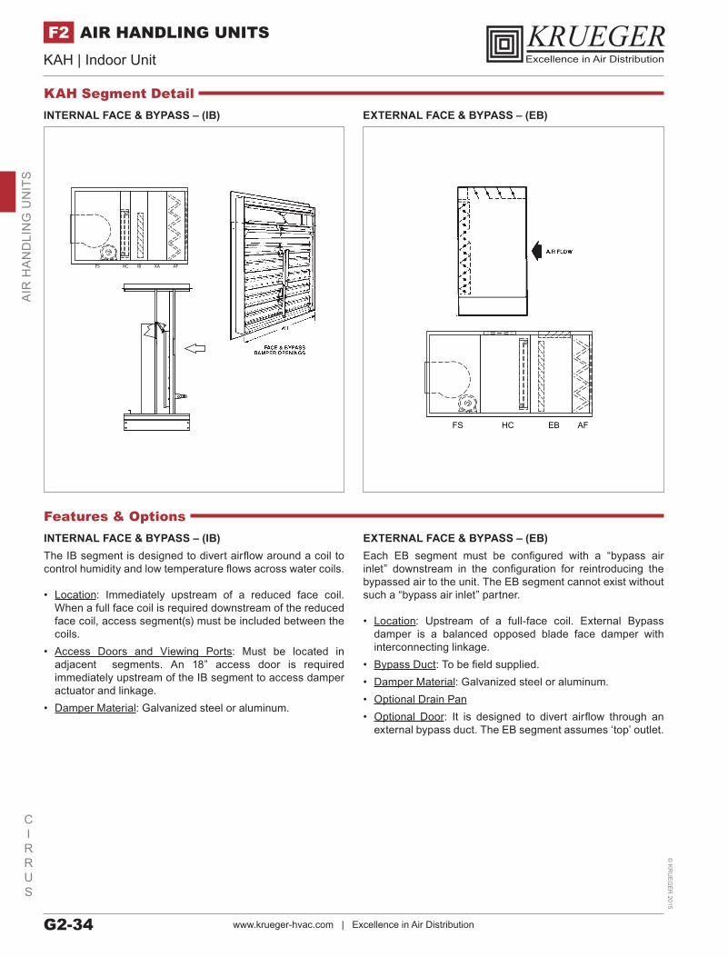
FS HC IB XA AF
FS HC EB AF
INTERNAL FACE & BYPASS – (IB) EXTERNAL FACE & BYPASS – (EB)
INTERNAL FACE & BYPASS – (IB)The IB segment is designed to divert airflow around a coil to control humidity and low temperature flows across water coils.
• Location: Immediately upstream of a reduced face coil. When a full face coil is required downstream of the reduced face coil, access segment(s) must be included between the coils.
• Access Doors and Viewing Ports: Must be located in adjacent segments. An 18” access door is required immediately upstream of the IB segment to access damper actuator and linkage.
• Damper Material: Galvanized steel or aluminum.
EXTERNAL FACE & BYPASS – (EB)Each EB segment must be configured with a “bypass air inlet” downstream in the configuration for reintroducing the bypassed air to the unit. The EB segment cannot exist without such a “bypass air inlet” partner.
• Location: Upstream of a full-face coil. External Bypass damper is a balanced opposed blade face damper with interconnecting linkage.
• Bypass Duct: To be field supplied.• Damper Material: Galvanized steel or aluminum.• Optional Drain Pan• Optional Door: It is designed to divert airflow through an
external bypass duct. The EB segment assumes ‘top’ outlet.
Features & Options
KAH Segment Detail
Providing You With Air Distribution Solutions G2-35
CIRRUS
KAH | Indoor Unit©
KR
UE
GE
R 2
015
AIR HANDLING UNITS F2A
IR H
AN
DLIN
G U
NITS
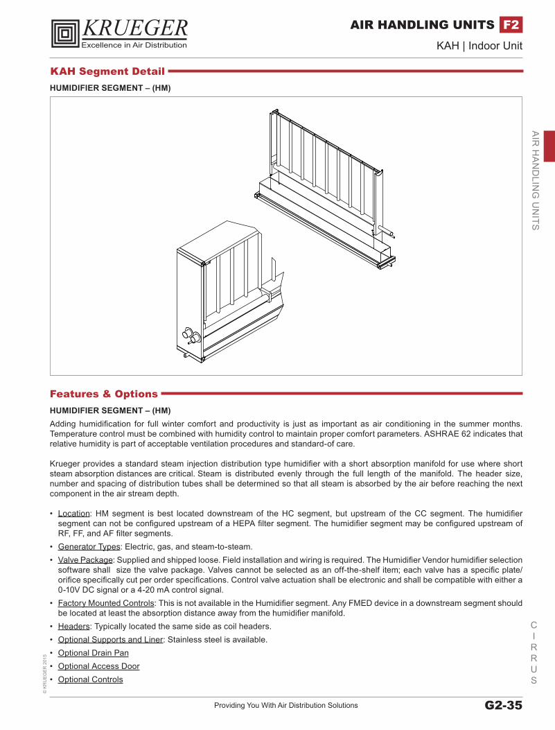
HUMIDIFIER SEGMENT – (HM)Adding humidification for full winter comfort and productivity is just as important as air conditioning in the summer months. Temperature control must be combined with humidity control to maintain proper comfort parameters. ASHRAE 62 indicates that relative humidity is part of acceptable ventilation procedures and standard-of care. Krueger provides a standard steam injection distribution type humidifier with a short absorption manifold for use where short steam absorption distances are critical. Steam is distributed evenly through the full length of the manifold. The header size, number and spacing of distribution tubes shall be determined so that all steam is absorbed by the air before reaching the next component in the air stream depth.
• Location: HM segment is best located downstream of the HC segment, but upstream of the CC segment. The humidifier segment can not be configured upstream of a HEPA filter segment. The humidifier segment may be configured upstream of RF, FF, and AF filter segments.
• Generator Types: Electric, gas, and steam-to-steam.• Valve Package: Supplied and shipped loose. Field installation and wiring is required. The Humidifier Vendor humidifier selection
software shall size the valve package. Valves cannot be selected as an off-the-shelf item; each valve has a specific plate/orifice specifically cut per order specifications. Control valve actuation shall be electronic and shall be compatible with either a 0-10V DC signal or a 4-20 mA control signal.
• Factory Mounted Controls: This is not available in the Humidifier segment. Any FMED device in a downstream segment should be located at least the absorption distance away from the humidifier manifold.
• Headers: Typically located the same side as coil headers.• Optional Supports and Liner: Stainless steel is available.• Optional Drain Pan• Optional Access Door• Optional Controls
Features & Options
HUMIDIFIER SEGMENT – (HM)
KAH Segment Detail
www.krueger-hvac.com | Excellence in Air DistributionG2-36
CIRRUS
KAH | Indoor Unit©
KR
UE
GE
R 2015
AIR HANDLING UNITSF2A
IR H
AN
DLI
NG
UN
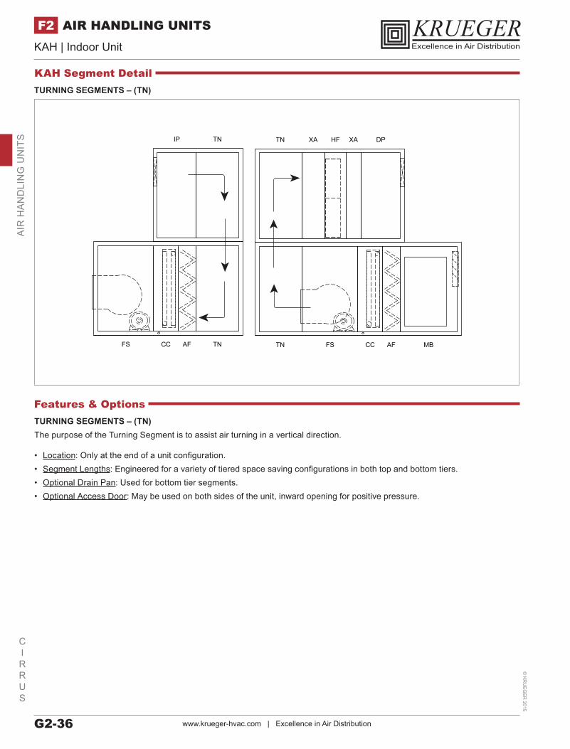
ITS DPXAHFXATN
TN FS CC AF MBFS CC AF TN
TNIP
TURNING SEGMENTS – (TN)The purpose of the Turning Segment is to assist air turning in a vertical direction.
• Location: Only at the end of a unit configuration.• Segment Lengths: Engineered for a variety of tiered space saving configurations in both top and bottom tiers.• Optional Drain Pan: Used for bottom tier segments.• Optional Access Door: May be used on both sides of the unit, inward opening for positive pressure.
Features & Options
TURNING SEGMENTS – (TN)
KAH Segment Detail
Providing You With Air Distribution Solutions G2-37
CIRRUS
KAH | Indoor Unit©
KR
UE
GE
R 2
015
AIR HANDLING UNITS F2A
IR H
AN
DLIN
G U
NITS
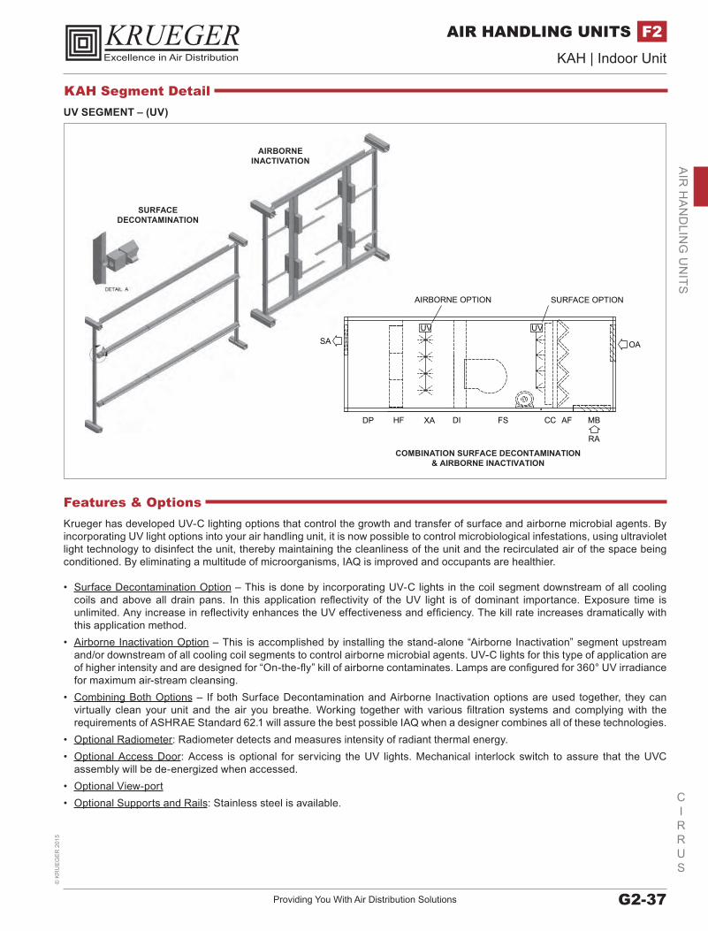
SURFACEDECONTAMINATION
AIRBORNEINACTIVATION
DP HF XA DI FS CC AF MB
OASA
RA
UV UV
AIRBORNE OPTION SURFACE OPTION
COMBINATION SURFACE DECONTAMINATION& AIRBORNE INACTIVATION
UV SEGMENT – (UV)
Krueger has developed UV-C lighting options that control the growth and transfer of surface and airborne microbial agents. By incorporating UV light options into your air handling unit, it is now possible to control microbiological infestations, using ultraviolet light technology to disinfect the unit, thereby maintaining the cleanliness of the unit and the recirculated air of the space being conditioned. By eliminating a multitude of microorganisms, IAQ is improved and occupants are healthier.
• Surface Decontamination Option – This is done by incorporating UV-C lights in the coil segment downstream of all cooling coils and above all drain pans. In this application reflectivity of the UV light is of dominant importance. Exposure time is unlimited. Any increase in reflectivity enhances the UV effectiveness and efficiency. The kill rate increases dramatically with this application method.
• Airborne Inactivation Option – This is accomplished by installing the stand-alone “Airborne Inactivation” segment upstream and/or downstream of all cooling coil segments to control airborne microbial agents. UV-C lights for this type of application are of higher intensity and are designed for “On-the-fly” kill of airborne contaminates. Lamps are configured for 360° UV irradiance for maximum air-stream cleansing.
• Combining Both Options – If both Surface Decontamination and Airborne Inactivation options are used together, they can virtually clean your unit and the air you breathe. Working together with various filtration systems and complying with the requirements of ASHRAE Standard 62.1 will assure the best possible IAQ when a designer combines all of these technologies.
• Optional Radiometer: Radiometer detects and measures intensity of radiant thermal energy.• Optional Access Door: Access is optional for servicing the UV lights. Mechanical interlock switch to assure that the UVC
assembly will be de-energized when accessed.• Optional View-port• Optional Supports and Rails: Stainless steel is available.
Features & Options
KAH Segment Detail
www.krueger-hvac.com | Excellence in Air DistributionG2-38
CIRRUS
KAH | Indoor Unit©
KR
UE
GE
R 2015
AIR HANDLING UNITSF2A
IR H
AN
DLI
NG
UN
ITS
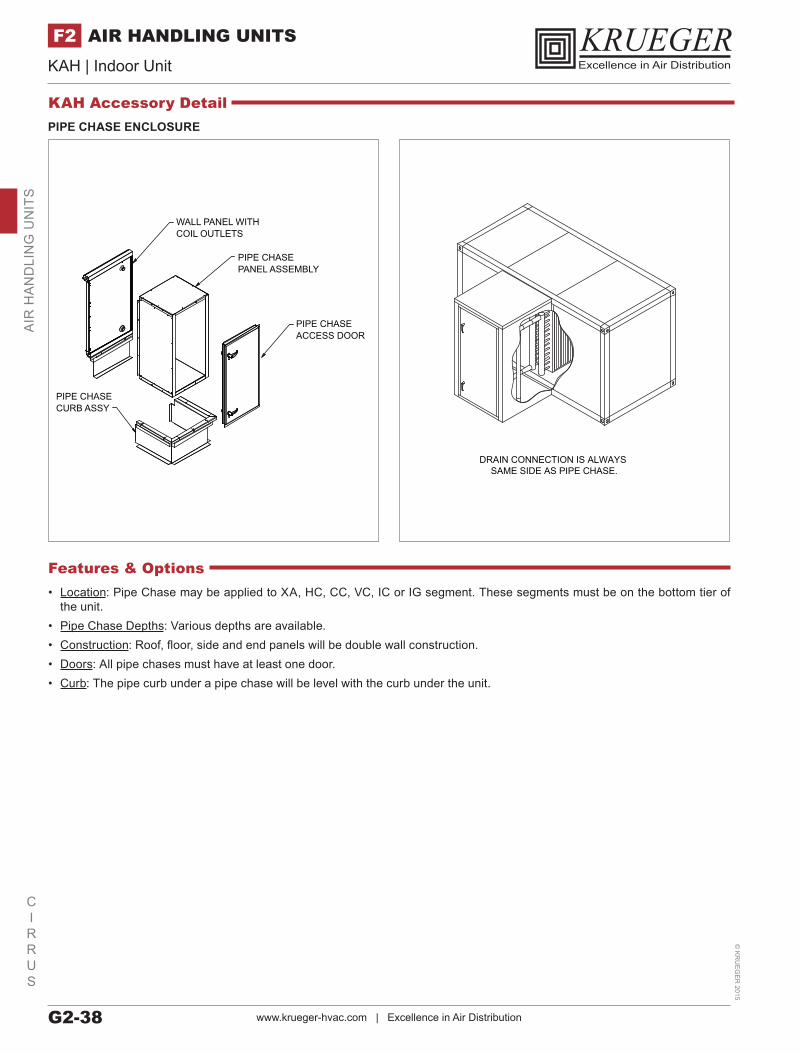
PIPE CHASE ENCLOSURE
WALL PANEL WITH COIL OUTLETS
PIPE CHASECURB ASSY
PIPE CHASE ACCESS DOOR
PIPE CHASEPANEL ASSEMBLY
DRAIN CONNECTION IS ALWAYS SAME SIDE AS PIPE CHASE.
• Location: Pipe Chase may be applied to XA, HC, CC, VC, IC or IG segment. These segments must be on the bottom tier of the unit.
• Pipe Chase Depths: Various depths are available.• Construction: Roof, floor, side and end panels will be double wall construction.• Doors: All pipe chases must have at least one door.• Curb: The pipe curb under a pipe chase will be level with the curb under the unit.
Features & Options
KAH Accessory Detail
Providing You With Air Distribution Solutions G2-39
CIRRUS
KAH | Indoor Unit©
KR
UE
GE
R 2
015
AIR HANDLING UNITS F2A
IR H
AN
DLIN
G U
NITS
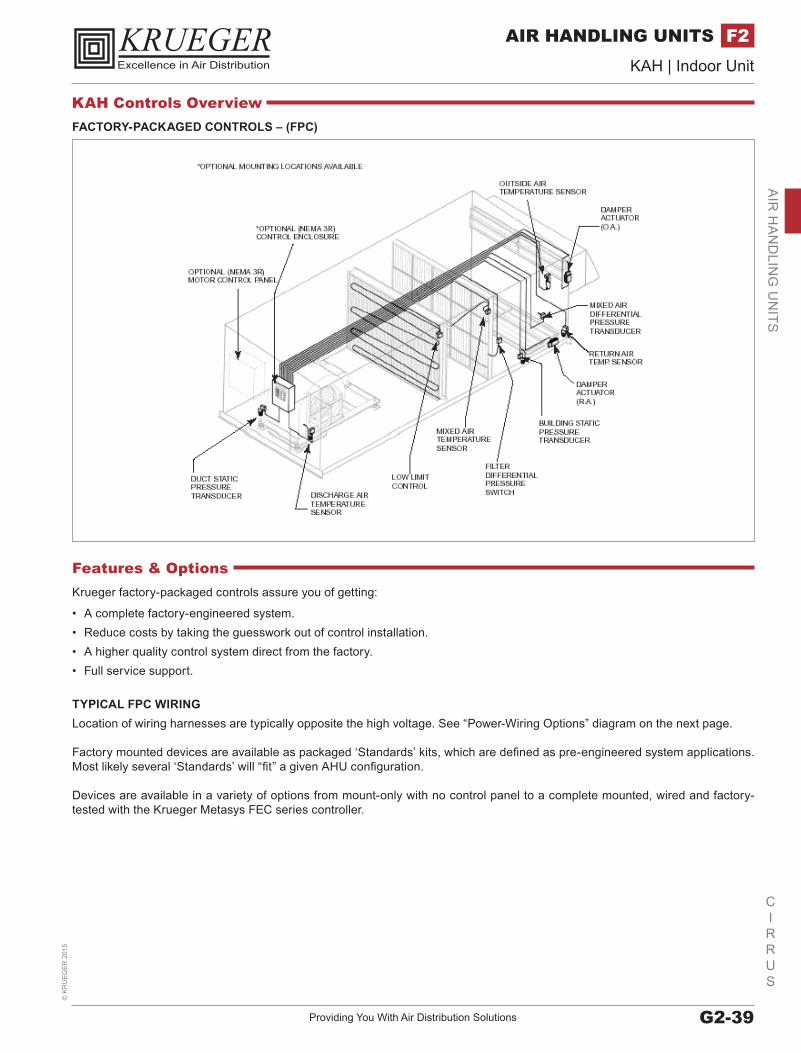
FACTORY-PACKAGED CONTROLS – (FPC)
Krueger factory-packaged controls assure you of getting:
• A complete factory-engineered system.• Reduce costs by taking the guesswork out of control installation.• A higher quality control system direct from the factory.• Full service support.
TYPICAL FPC WIRINGLocation of wiring harnesses are typically opposite the high voltage. See “Power-Wiring Options” diagram on the next page.
Factory mounted devices are available as packaged ‘Standards’ kits, which are defined as pre-engineered system applications. Most likely several ‘Standards’ will “fit” a given AHU configuration.
Devices are available in a variety of options from mount-only with no control panel to a complete mounted, wired and factory-tested with the Krueger Metasys FEC series controller.
Features & Options
KAH Controls Overview
www.krueger-hvac.com | Excellence in Air DistributionG2-40
CIRRUS
KAH | Indoor Unit©
KR
UE
GE
R 2015
AIR HANDLING UNITSF2A
IR H
AN
DLI
NG
UN
ITS
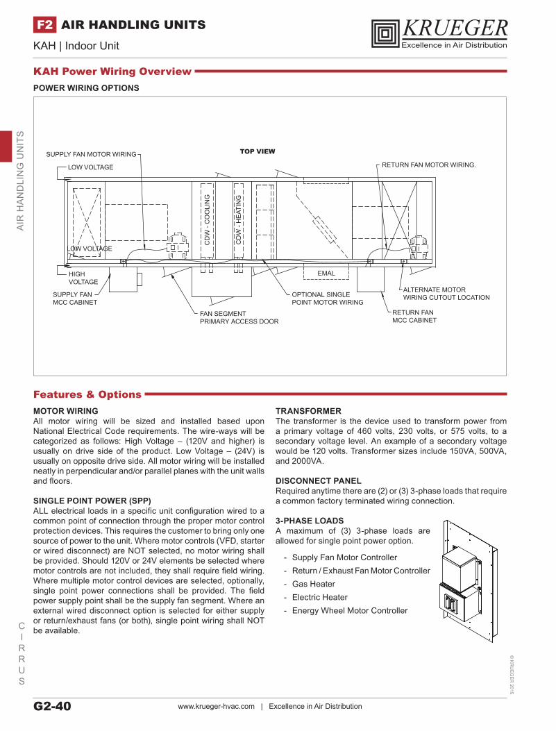
POWER WIRING OPTIONS
FAN SEGMENTPRIMARY ACCESS DOOR
OPTIONAL SINGLE POINT MOTOR WIRING
SUPPLY FANMCC CABINET
SUPPLY FAN MOTOR WIRING
CD
W -
CO
OLI
NG
CD
W -
HE
ATIN
G
ALTERNATE MOTORWIRING CUTOUT LOCATION
RETURN FANMCC CABINET
EMAL
RETURN FAN MOTOR WIRING.LOW VOLTAGE
TOP VIEW
HIGHVOLTAGE
LOW VOLTAGE
MOTOR WIRING All motor wiring will be sized and installed based upon National Electrical Code requirements. The wire-ways will be categorized as follows: High Voltage – (120V and higher) is usually on drive side of the product. Low Voltage – (24V) is usually on opposite drive side. All motor wiring will be installed neatly in perpendicular and/or parallel planes with the unit walls and floors.
SINGLE POINT POWER (SPP)ALL electrical loads in a specific unit configuration wired to a common point of connection through the proper motor control protection devices. This requires the customer to bring only one source of power to the unit. Where motor controls (VFD, starter or wired disconnect) are NOT selected, no motor wiring shall be provided. Should 120V or 24V elements be selected where motor controls are not included, they shall require field wiring. Where multiple motor control devices are selected, optionally, single point power connections shall be provided. The field power supply point shall be the supply fan segment. Where an external wired disconnect option is selected for either supply or return/exhaust fans (or both), single point wiring shall NOT be available.
TRANSFORMERThe transformer is the device used to transform power from a primary voltage of 460 volts, 230 volts, or 575 volts, to a secondary voltage level. An example of a secondary voltage would be 120 volts. Transformer sizes include 150VA, 500VA, and 2000VA.
DISCONNECT PANEL Required anytime there are (2) or (3) 3-phase loads that require a common factory terminated wiring connection.
3-PHASE LOADS A maximum of (3) 3-phase loads are allowed for single point power option.
- Supply Fan Motor Controller - Return / Exhaust Fan Motor Controller - Gas Heater - Electric Heater - Energy Wheel Motor Controller
Features & Options
KAH Power Wiring Overview

Providing You With Air Distribution Solutions G2-41
CIRRUS
KAH | Indoor Unit©
KR
UE
GE
R 2
015
AIR HANDLING UNITS F2A
IR H
AN
DLIN
G U
NITS
DOOR AND DISCHARGE LOCATIONS
REAR (R)
HINGES
DOOR
DOOR
DOOR
DOOR DOOR
DOORHINGES
HINGESHINGES
HINGES
HINGES
TOP (T) BOTTOM (B)
REAR INVERTED (RI) TOP INVERTED (TI) BOTTOM INVERTD (BI)
DOOR
DOOR
HINGES
HINGES
FRONT (F)
FRONT INVERTED (FI)
AIRFLOW
Features & OptionsFan and fan motor may be oriented in the fan segment. Consideration must be given to which orientation is used where. Upstream and downstream usage follow.
WHERE DOORS ARE USED:• Rear / Rear-Inverted Discharge – Upstream• Top / Bottom Discharge – Downstream• Front / Front Inverted Discharge – Downstream• Top-Inverted / Bottom-Inverted Discharge – Upstream
KAH Discharge Overview
www.krueger-hvac.com | Excellence in Air DistributionG2-42
CIRRUS
KAH | Indoor Unit©
KR
UE
GE
R 2015
AIR HANDLING UNITSF2A
IR H
AN
DLI
NG
UN
ITS
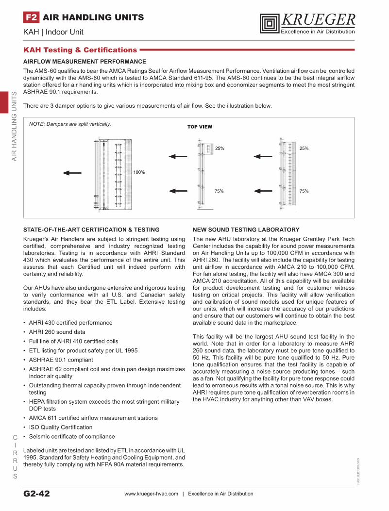
KAH Testing & CertificationsAIRFLOW MEASUREMENT PERFORMANCEThe AMS-60 qualifies to bear the AMCA Ratings Seal for Airflow Measurement Performance. Ventilation airflow can be controlled dynamically with the AMS-60 which is tested to AMCA Standard 611-95. The AMS-60 continues to be the best integral airflow station offered for air handling units which is incorporated into mixing box and economizer segments to meet the most stringent ASHRAE 90.1 requirements.
There are 3 damper options to give various measurements of air flow. See the illustration below.
STATE-OF-THE-ART CERTIFICATION & TESTINGKrueger’s Air Handlers are subject to stringent testing using certified, comprehensive and industry recognized testing laboratories. Testing is in accordance with AHRI Standard 430 which evaluates the performance of the entire unit. This assures that each Certified unit will indeed perform with certainty and reliability.
Our AHUs have also undergone extensive and rigorous testing to verify conformance with all U.S. and Canadian safety standards, and they bear the ETL Label. Extensive testing includes:
• AHRI 430 certified performance• AHRI 260 sound data• Full line of AHRI 410 certified coils• ETL listing for product safety per UL 1995• ASHRAE 90.1 compliant• ASHRAE 62 compliant coil and drain pan design maximizes
indoor air quality• Outstanding thermal capacity proven through independent
testing• HEPA filtration system exceeds the most stringent military
DOP tests• AMCA 611 certified airflow measurement stations• ISO Quality Certification• Seismic certificate of compliance
Labeled units are tested and listed by ETL in accordance with UL 1995, Standard for Safety Heating and Cooling Equipment, and thereby fully complying with NFPA 90A material requirements.
NEW SOUND TESTING LABORATORYThe new AHU laboratory at the Krueger Grantley Park Tech Center includes the capability for sound power measurements on Air Handling Units up to 100,000 CFM in accordance with AHRI 260. The facility will also include the capability for testing unit airflow in accordance with AMCA 210 to 100,000 CFM. For fan alone testing, the facility will also have AMCA 300 and AMCA 210 accreditation. All of this capability will be available for product development testing and for customer witness testing on critical projects. This facility will allow verification and calibration of sound models used for unique features of our units, which will increase the accuracy of our predictions and ensure that our customers will continue to obtain the best available sound data in the marketplace.
This facility will be the largest AHU sound test facility in the world. Note that in order for a laboratory to measure AHRI 260 sound data, the laboratory must be pure tone qualified to 50 Hz. This facility will be pure tone qualified to 50 Hz. Pure tone qualification ensures that the test facility is capable of accurately measuring a noise source producing tones – such as a fan. Not qualifying the facility for pure tone response could lead to erroneous results with a tonal noise source. This is why AHRI requires pure tone qualification of reverberation rooms in the HVAC industry for anything other than VAV boxes.
100%
25%
75%
25%
75%
TOP VIEWNOTE: Dampers are split vertically.
Providing You With Air Distribution Solutions G2-43
CIRRUS
KAH | Indoor Unit©
KR
UE
GE
R 2
015
AIR HANDLING UNITS F2A
IR H
AN
DLIN
G U
NITS
www.krueger-hvac.com | Excellence in Air DistributionG2-44
CIRRUS
KAH | Indoor Unit©
KR
UE
GE
R 2015
AIR HANDLING UNITSF2A
IR H
AN
DLI
NG
UN
ITS
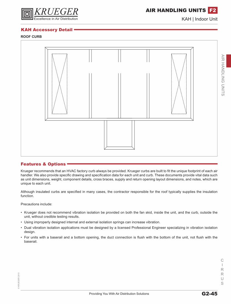
Providing You With Air Distribution Solutions G2-45
CIRRUS
KAH | Indoor Unit©
KR
UE
GE
R 2
015
AIR HANDLING UNITS F2A
IR H
AN
DLIN
G U
NITS
ROOF CURB
Krueger recommends that an HVAC factory curb always be provided. Krueger curbs are built to fit the unique footprint of each air handler. We also provide specific drawing and specification data for each unit and curb. These documents provide vital data such as unit dimensions, weight, component details, cross braces, supply and return opening layout dimensions, and notes, which are unique to each unit.
Although insulated curbs are specified in many cases, the contractor responsible for the roof typically supplies the insulation function.
Precautions include:
• Krueger does not recommend vibration isolation be provided on both the fan skid, inside the unit, and the curb, outside the unit, without credible testing results.
• Using improperly designed internal and external isolation springs can increase vibration.• Dual vibration isolation applications must be designed by a licensed Professional Engineer specializing in vibration isolation
design.• For units with a baserail and a bottom opening, the duct connection is flush with the bottom of the unit, not flush with the
baserail.
Features & Options
KAH Accessory Detail
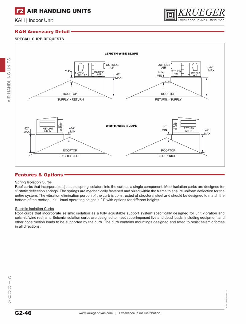
www.krueger-hvac.com | Excellence in Air DistributionG2-46
CIRRUS
KAH | Indoor Unit©
KR
UE
GE
R 2015
AIR HANDLING UNITSF2A
IR H
AN
DLI
NG
UN
ITS
SUPPLYAIR
RETURNAIR
OUTSIDEAIR
ROOFTOP
SUPPLY > RETURN RETURN > SUPPLY
ROOFTOP
OUTSIDEAIR
RETURNAIR SUPPLY
AIR
ROOFTOP ROOFTOP
RETURNAIR IN
RETURNAIR IN
PIP
EC
HA
SE
PIP
EC
HA
SE
RIGHT > LEFT LEFT > RIGHT
WIDTH-WISE SLOPE
LENGTH-WISE SLOPE
*14”42”
MAX
42”MAX
42”MAX
42”MAX
14”MIN
14”MIN
14”MIN
Spring Isolation CurbsRoof curbs that incorporate adjustable spring isolators into the curb as a single component. Most isolation curbs are designed for 1” static deflection springs. The springs are mechanically fastened and sized within the frame to ensure uniform deflection for the entire system. The vibration elimination portion of the curb is constructed of structural steel and should be designed to match the bottom of the rooftop unit. Usual operating height is 21” with options for different heights.
Seismic Isolation CurbsRoof curbs that incorporate seismic isolation as a fully adjustable support system specifically designed for unit vibration and seismic/wind restraint. Seismic isolation curbs are designed to meet superimposed live and dead loads, including equipment and other construction loads to be supported by the curb. The curb contains mountings designed and rated to resist seismic forces in all directions.
Features & Options
SPECIAL CURB REQUESTS
KAH Accessory Detail