ahmed musa, john medrano, virgillio gonzalez, cecil thomas university of texas at el paso
DESCRIPTION
Ahmed Musa, John Medrano, Virgillio Gonzalez, Cecil Thomas University of Texas at El Paso. Circuit Establishment in a Hybrid Optical-CDMA and WDM All-Optical Network Using the Flooding Mechanism. Mehdi Shadaram University of Texas at San Antonio. Outline. - PowerPoint PPT PresentationTRANSCRIPT
Ahmed Musa, John Medrano, Virgillio Gonzalez, Cecil Thomas
University of Texas at El Paso
Circuit Establishment in a Hybrid Optical-CDMA and WDM All-Optical Network Using the Flooding Mechanism
Mehdi ShadaramUniversity of Texas at San Antonio
* Introduction - A high demand on higher capacities ( Why all-optical network?)
- Approaches to make the transmission medium has a scalable bandwidth (BW) capacity
* Backbone network- Optical-Optical-Optical (OOO)- Optical-Electrical-Optical (OEO)
* Routing Benefits and Disadvantages
* Proposed routing algorithm
* Routing (Setup Optimal Lightpath) Steps
* Routing Implementation Using Flooding Mechanism
* Example
* Conclusions
Outline
Introduction
• A high demand on higher capacities because ofMultimedia services.Video conferencesInternet.Environmental remote sensing.Medical imaging
• Approaches to make the transmission medium has a scalable bandwidth (BW) capacity
Install more fiber (costly) Exploit the BW of existing fiber using higher data rates and
multiplexing techniques such as Wavelength Division Multiplexing (WDM).
- Coarse WDM (# of Lambdas λ’s < 10)
- Dense WDM (# of λ’s > 10)
Time Division Multiplexing (TDM). Code Division Multiplexing (CDM).
Backbone networkOptical – Electrical – Optical (OEO)
Optical – Optical – Optical (OOO or Photonic NW)
Photonic networks
Advantages– Solve the electronic equipment bottleneck
– Exploit the existing network
Disadvantages - Photonic NW is a complex system ( a large number of
different functions must cooperate for a network such as
– transmission
– Routing and Switching
– Control and management
– etc.
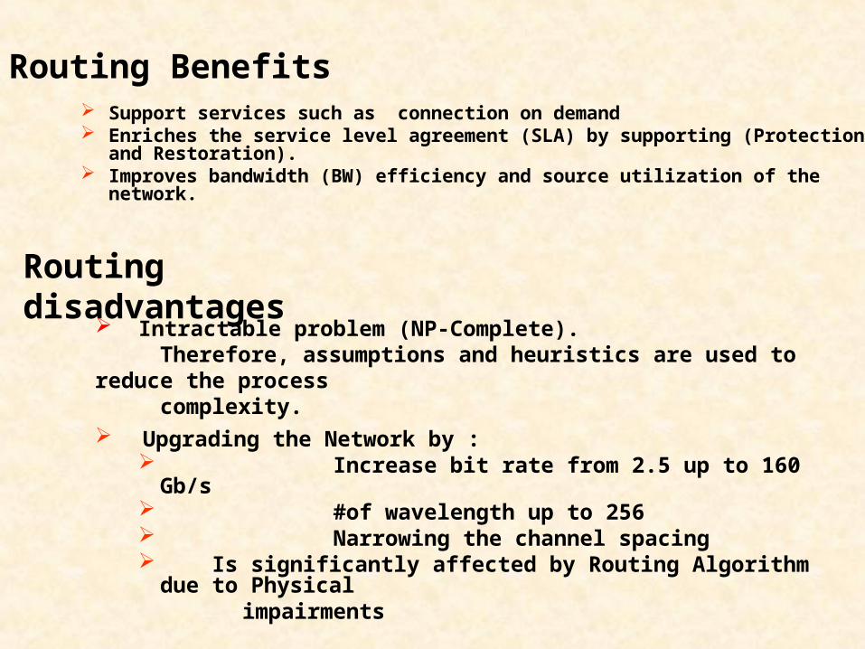
Routing Benefits Support services such as connection on demand Enriches the service level agreement (SLA) by supporting (Protection and
Restoration). Improves bandwidth (BW) efficiency and source utilization of the network.
Intractable problem (NP-Complete). Therefore, assumptions and heuristics are used to reduce the process complexity.
Routing disadvantages
Upgrading the Network by : Increase bit rate from 2.5 up to 160 Gb/s #of wavelength up to 256 Narrowing the channel spacing Is significantly affected by Routing Algorithm due to Physical impairments
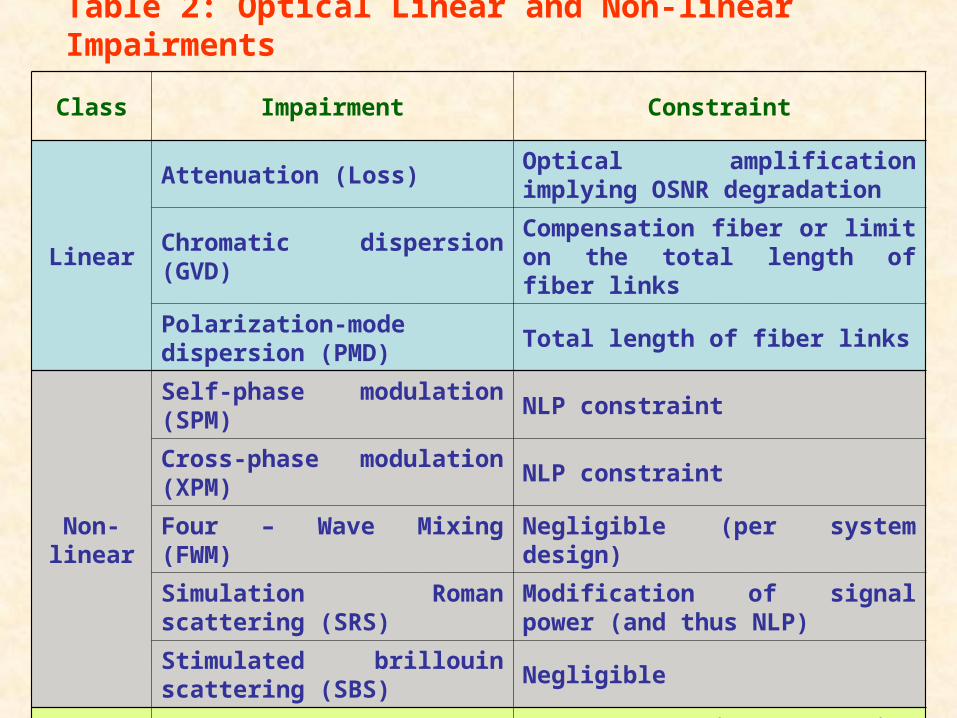
Table 2: Optical Linear and Non-linear Impairments
Class Impairment Constraint
Linear
Attenuation (Loss)Optical amplification implying OSNR degradation
Chromatic dispersion (GVD)Compensation fiber or limit on the total length of fiber links
Polarization-mode dispersion (PMD)
Total length of fiber links
Non-linear
Self-phase modulation (SPM) NLP constraint
Cross-phase modulation (XPM) NLP constraint
Four – Wave Mixing (FWM) Negligible (per system design)
Simulation Roman scattering (SRS)
Modification of signal power (and thus NLP)
Stimulated brillouin scattering (SBS)
Negligible
NoiseAmplifier spontaneous emission (ASE)
OSNR degradation (resulting in constraint on the number of fiber spans)
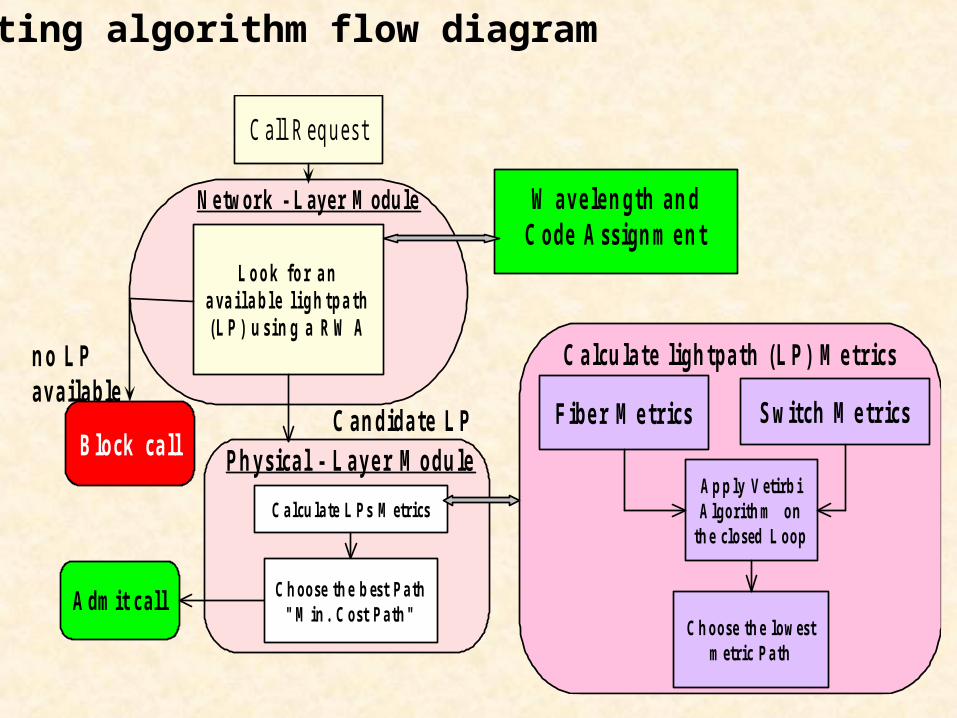
N e twor k - Laye r M odu le
C all R eq u es t
L o o k f o r a na va i l a b l e l i g h t p a t h( L P ) u s i n g a R W A
B lo ck ca ll
n o L Pa v a ila ble
A dm it c al l
W a v e le n g th a n dC o de A s s ig n m e n t
C a lcu la te L P s M etrics
C a n dida te L PPh y s ica l - L a y e r M o du le
C h oo se th e b est P a th" M in . C ost P a th "
S witch M e tricsF ibe r M e trics
A p p ly V etirb iA lgo rith m on
th e clo sed L o op
C h oo se th e low estm etric P a th
C a lcu la te lig h tpa th (L P) M e trics
Routing algorithm flow diagram
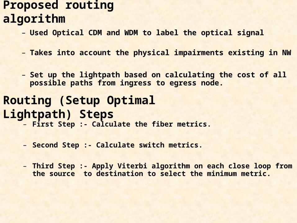
Proposed routing algorithm
– Used Optical CDM and WDM to label the optical signal
– Takes into account the physical impairments existing in NW
– Set up the lightpath based on calculating the cost of all possible paths from ingress to egress node.
Routing (Setup Optimal Lightpath) Steps– First Step :- Calculate the fiber metrics.
– Second Step :- Calculate switch metrics.
– Third Step :- Apply Viterbi algorithm on each close loop from the source to destination to select the minimum metric.
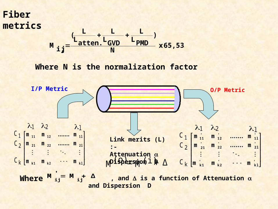
Fiber metrics
65,535x N
)PMDLL
GVDLL
atten.LL(
ji,M
Where N is the normalization factor
I/P Metric O/P Metric
Link merits (L) :-Attenuation Dispersion D
Where Δ M 'M ijij , and is a function of Attenuation and Dispersion
D
Δ M (i) M(o)
klk2k1
2 l2 22 1
1 l1 211
mmm
m.......mm
m.......mm
1 2 lC1C2
Ck
klk2k1
2 l2 22 1
1 l1 2
m 'm 'm '
m '.......m 'm '
m '.......m '
1 2 lC1C2
Ck
11m '
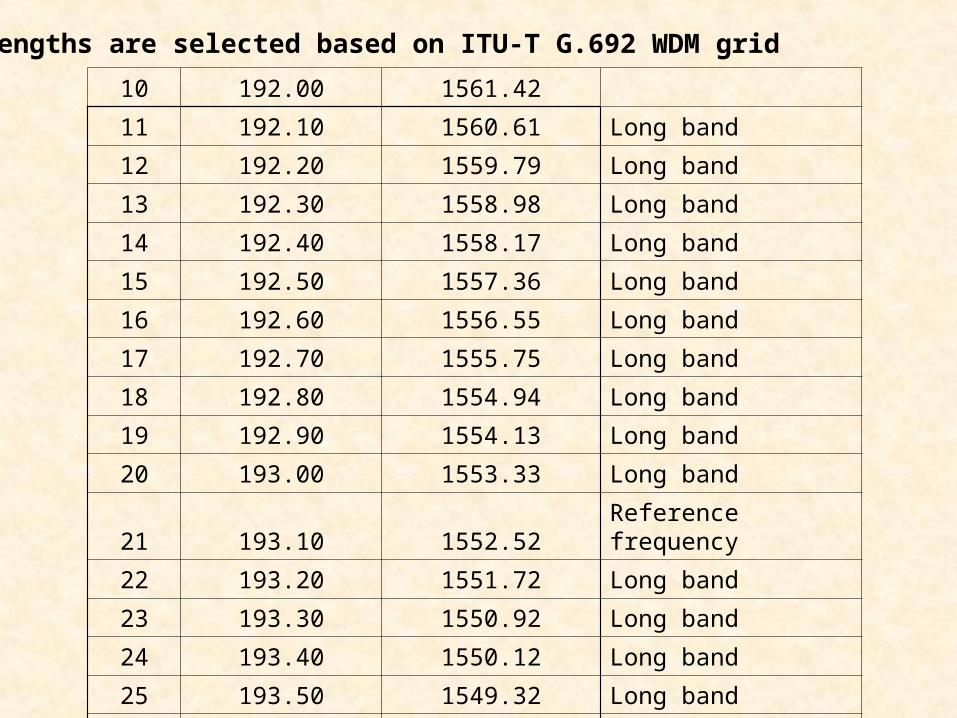
Wavelengths are selected based on ITU-T G.692 WDM grid
10 192.00 1561.42
11 192.10 1560.61 Long band
12 192.20 1559.79 Long band
13 192.30 1558.98 Long band
14 192.40 1558.17 Long band
15 192.50 1557.36 Long band
16 192.60 1556.55 Long band
17 192.70 1555.75 Long band
18 192.80 1554.94 Long band
19 192.90 1554.13 Long band
20 193.00 1553.33 Long band
21 193.10 1552.52 Reference frequency
22 193.20 1551.72 Long band
23 193.30 1550.92 Long band
24 193.40 1550.12 Long band
25 193.50 1549.32 Long band
26 193.60 1548.51 Long band
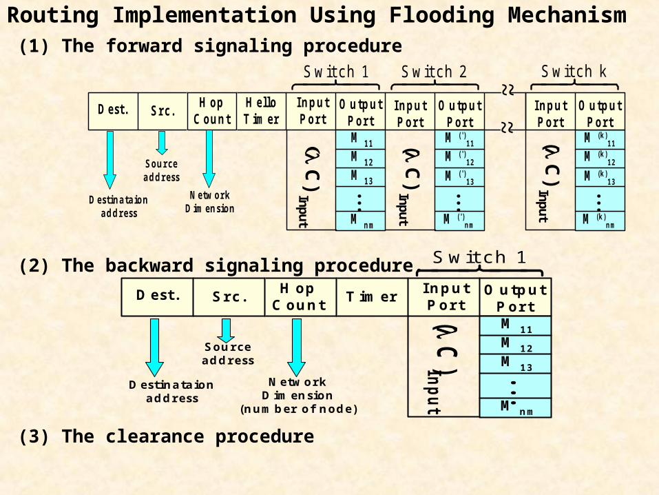
Routing Implementation Using Flooding Mechanism(1) The forward signaling procedure
(2) The backward signaling procedure.
(3) The clearance procedure
D e st . S r c .H o p
C o u n tH e lloT im e r
In p u tP o r t
O u tp u tP o r t
In p u tP o r t
O u tp u tP o r t
M 11
M 1 2
M 1 3
M n m
...
M ( ')1 1
M ( ')n m
...
M ( ')1 2
M ( ')1 3
~ ~M (k )
1 1
M (k )n m
...
M (k )1 2
M (k )1 3
In p u tP o r t
O u tp u tP o r t
~ ~S wit ch 1 S wit ch 2 S wit ch k
C) Input
D estin a ta io na d d ress
S o u rcea d d ress
N etw o rkD im en sio n
( C
) Input
( C
) Input
D e st . S r c .H o p
C o u n tT im e r
In p u tP o r t
O u tp u tP o r tM 11
M 1 2
M 1 3
M n m
...
S wit ch 1
D estin a ta io na d d ress
S o u rcea d d ress
N etw o rkD im en sio n
(n u m b er o f n o d e )
( C
) Inp
ut
2 x 2 x 2 x 2
2
3
S wit ch # X
1
S wit ch Y
λ1C1 λ1C2 λ2C1 λ2C2
D A 310ps 31
1111
4
λ1C2
76
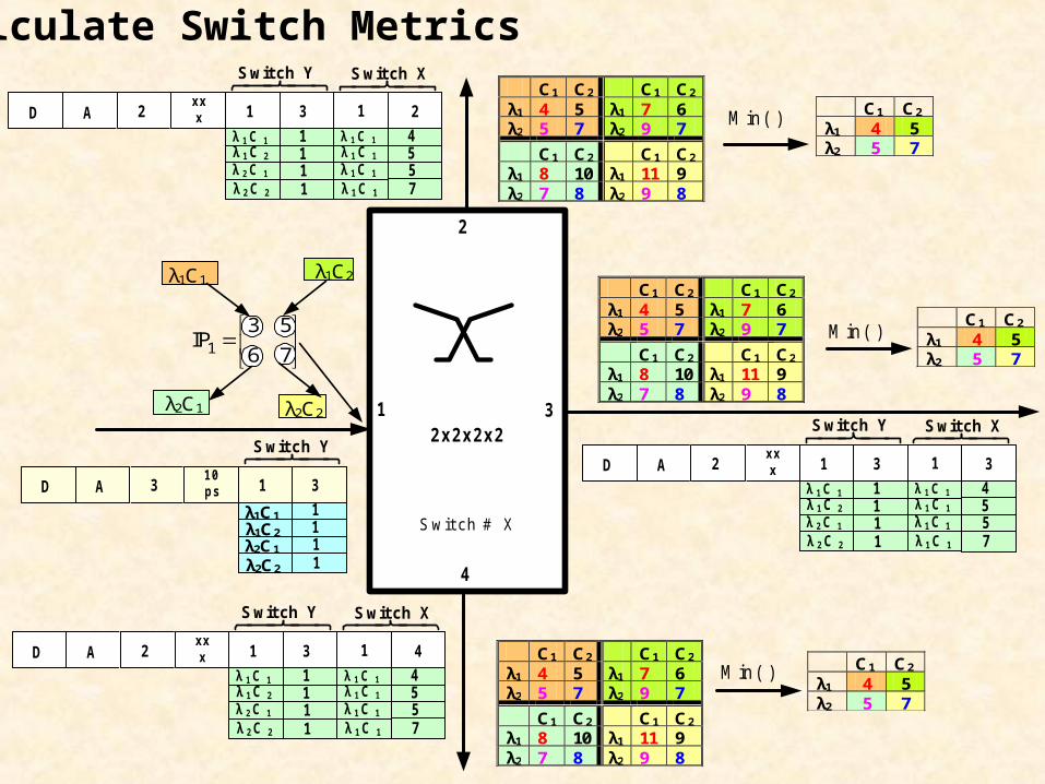
53 IP1
λ1C1
λ2C1 λ2C2
C1 C2 C1 C2 λ1 4 5 λ1 7 6 λ2 5 7 λ2 9 7
C1 C2 C1 C2 λ1 8 10 λ1 11 9 λ2 7 8 λ2 9 8
C1 C2
λ1 4 5 λ2 5 7
M in( )
C1 C2 C1 C2 λ1 4 5 λ1 7 6 λ2 5 7 λ2 9 7
C1 C2 C1 C2 λ1 8 10 λ1 11 9 λ2 7 8 λ2 9 8
C1 C2
λ1 4 5 λ2 5 7
M in( )
C1 C2 C1 C2 λ1 4 5 λ1 7 6 λ2 5 7 λ2 9 7
C1 C2 C1 C2 λ1 8 10 λ1 11 9 λ2 7 8 λ2 9 8
C1 C2
λ1 4 5 λ2 5 7
M in( )
S witch Y
λ 1 C 1
λ 1 C 2
λ 2 C 1
λ 2 C 2
D A 2x xx 31
1111
λ 1 C 1
λ 1 C 1
λ 1 C 1
λ 1 C 1
4557
S witch X
1 3
S witch Y
λ 1 C 1
λ 1 C 2
λ 2 C 1
λ 2 C 2
D A 2x xx 31
1111
λ 1 C 1
λ 1 C 1
λ 1 C 1
λ 1 C 1
4557
S witch X
1 4
S witch Y
λ 1 C 1λ 1 C 2
λ 2 C 1
λ 2 C 2
D A 2x xx 31
1111
λ 1 C 1
λ 1 C 1
λ 1 C 1
λ 1 C 1
4557
S witch X
1 2
Calculate Switch Metrics

C1 C2
λ1 1.0 1.0 λ 2 1.0 1.0
C1 C2
λ1 1.0 1.0 λ 2 1.0 1.0
Switch C
2x2x2
2
13
4
C1 C2
λ1 ? 1.0 λ 2 1.0 1.0 C
C1 C2
λ1 1.0 1.0 λ2 1.0 1.0
L 1
C1 C2
λ1 ? 1.0 λ 2 1.0 1.0
C1 C2
λ1 ? 1.0 λ 2 1.0 1.0
L 2
C1 C2
λ1 ? 1.0 λ 2 1.0 1.0
C1 C2
λ1 ? 1.0 λ 2 1.0 1.0
C1 C2
λ1 1.0 1.0 λ 2 1.0 1.0 A
C1 C2
λ1 ? 1.0 λ 2 1.0 1.0
L3
C1 C2
λ1 1.0 1.0 λ 2 1.0 1.0
Switch B
Switch A
2x2x22
1 3
4 2x2x22
13
4
B C1 C2
λ1 1.0 1.0 λ 2 1.0 1.0
N e tw o r k M a n a g e r( S i g n a l Tr a n s fe r P o i n t )
S ig n al in g L in k
Fibe r L in k
Data start brusted through using the selected path (A B C)
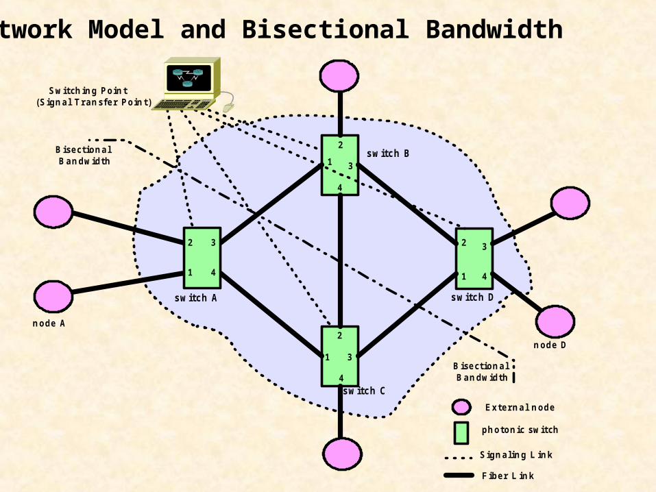
S wit ch in g Po in t(S ig n a l Tra n s fe r Po in t )
s w itc h A
s w itc h B
1
2
3
4
1
2 3
4
1
2
3
4
1
2 3
4
s w itc h C
s w itc h D
n o de A
n o de D
Ex te rn a l n o de
ph o to n ic s wit ch
S ig n a lin g L in k
Fibe r L in k
B is e ct io n a l B a n dwidth
B is e ct io n a l B a n dwidth
Network Model and Bisectional Bandwidth
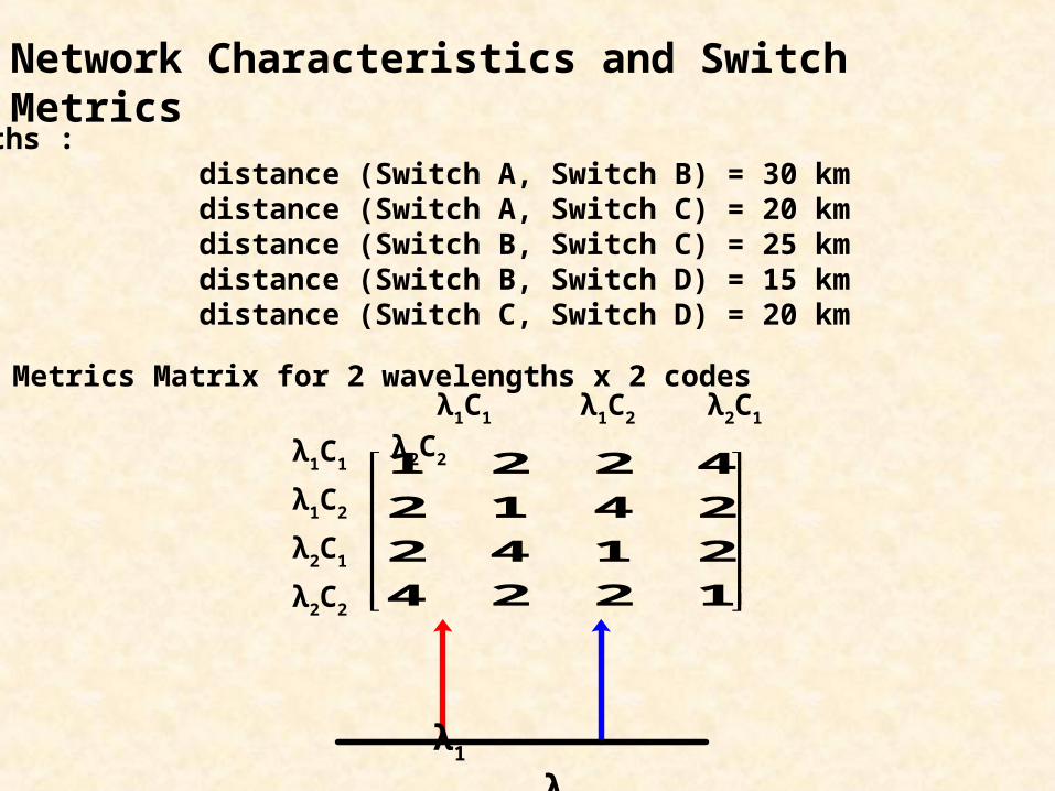
Network Characteristics and Switch Metrics
Switch Metrics Matrix for 2 wavelengths x 2 codes
Fiber Lengths : distance (Switch A, Switch B) = 30 km distance (Switch A, Switch C) = 20 km distance (Switch B, Switch C) = 25 km distance (Switch B, Switch D) = 15 km distance (Switch C, Switch D) = 20 km
λ1C1 λ1C2 λ2C1 λ2C2
1224
2142
2412
4221λ1C1
λ1C2
λ2C1
λ2C2
λ1 λ2
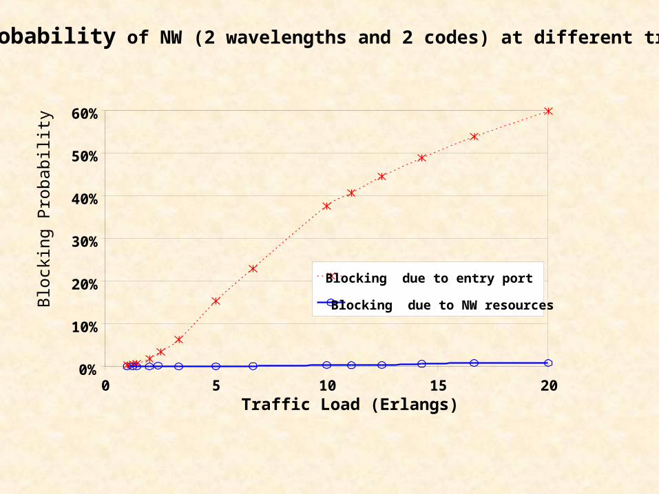
0%
10%
20%
30%
40%
50%
60%
0 5 10 15 20Traffic Load (Erlangs)
Blo
ckin
g P
roba
bilit
y
Blocking due to entry port
Blocking due to NW resources
Blocking probability of NW (2 wavelengths and 2 codes) at different traffic load
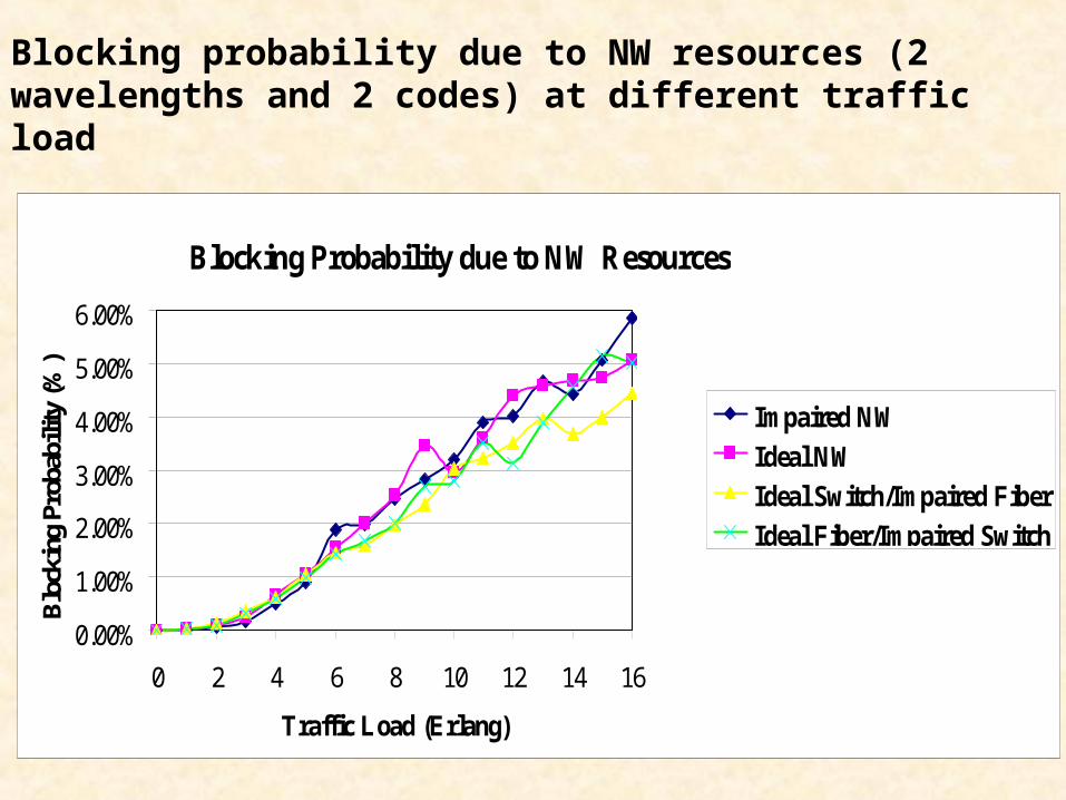
Blocking probability due to NW resources (2 wavelengths and 2 codes) at different traffic load
Blocking Probability due to NW Resources
0.00%
1.00%
2.00%
3.00%
4.00%
5.00%
6.00%
0 2 4 6 8 10 12 14 16
Traffic Load (Erlang)
Blo
ckin
g Pr
obab
ility
(%)
Impaired NW
Ideal NW
Ideal Switch/Impaired Fiber
Ideal Fiber/Impaired Switch
Conclusions
This algorithm help improving the NW Performance.
Flooding mechanism is used to set up the path (used in the control plane of the network independent of the information path.
Flooding mechanism is emulated in in the network manager.