agrément certificate 19/5671 nvelope rainscreen systems ... · nvelope rainscreen systems nvelope...
TRANSCRIPT
Page 1 of 16
SFS Group Fastening Technology Ltd Unit A City Park Watchmead, Welwyn Garden City Hertfordshire AL7 1LT Tel: 01707 333396 Agrément Certificate e-mail: [email protected] 19/5671 website: www.nvelope.com Product Sheet 1
NVELOPE RAINSCREEN SYSTEMS NVELOPE RAINSCREEN CLADDING SUPPORT SYSTEMS
This Agrément Certificate Product Sheet (1) relates to Nvelope Rainscreen Cladding Support Systems, for use as a sub-frame to support cladding on the external or internal wall structure of new or existing buildings.
(1) Hereinafter referred to as ‘Certificate’.
CERTIFICATION INCLUDES:
• factors relating to compliance with Building Regulations where applicable
• factors relating to additional non-regulatory information where applicable
• independently verified technical specification • assessment criteria and technical investigations • design considerations • installation guidance • regular surveillance of production • formal three-yearly review.
KEY FACTORS ASSESSED
Mechanical resistance and stability — the systems can be designed to support the cladding and to transfer the design loads to the substrate wall structure safely (see section 6). Behaviour in relation to fire — the systems (fixings, brackets, rails, carriers and adaptors) have an A1 reaction to fire classification in accordance with the national Building Regulations (see section 7). Drainage and ventilation — provided correct details are adopted, the systems can provide adequate drainage and ventilation behind the cladding (see section 8). Durability — the systems will have a service life in excess of 35 years (see section 10).
The BBA has awarded this Certificate to the company named above for the systems described herein. These systems have been assessed by the BBA as being fit for their intended use provided they are installed, used and maintained as set out in this Certificate.
On behalf of the British Board of Agrément
Date of First issue: 24 June 2019
Paul Valentine Technical Excellence Director
Claire Curtis-Thomas Chief Executive
The BBA is a UKAS accredited certification body – Number 113. The schedule of the current scope of accreditation for product certification is available in pdf format via the UKAS link on the BBA website at www.bbacerts.co.uk Readers are advised to check the validity and latest issue number of this Agrément Certificate by either referring to the BBA website or contacting the BBA direct.
Any photographs are for illustrative purposes only, do not constitute advice and should not be relied upon.
British Board of Agrément Bucknalls Lane Watford Herts WD25 9BA
©2019
tel: 01923 665300
[email protected] www.bbacerts.co.uk
Page 2 of 16
Regulations
In the opinion of the BBA, Nvelope Rainscreen Cladding Support Systems, if installed, used and maintained in accordance with this Certificate, can satisfy or contribute to satisfying the relevant requirements of the following Building Regulations (the presence of a UK map indicates that the subject is related to the Building Regulations in the region or regions of the UK depicted):
The Building Regulations 2010 (England and Wales) (as amended)
Requirement: A1 Loading Comment: The systems can be designed to adequately transfer the design loads from the cladding
to the substrate wall structure. See section 6 of this Certificate. Requirement: B4(1) External fire spread Comment: In England, the systems are unrestricted by this Requirement. See section 7.1 of this
Certificate. Regulation: Regulation:
7 7(1)
Materials and workmanship (applicable to Wales only) Materials and workmanship (applicable to England only)
Comment: Regulation: Comment:
7(2)
The systems are acceptable. See section 10.1 and the Installation part of this Certificate. Materials and workmanship (applicable to England only) The systems are unrestricted by this Regulation. See section 7.1 of this Certificate.
The Building (Scotland) Regulations 2004 (as amended)
Regulation: 8(1) Durability, workmanship and fitness of materials Comment: The systems are acceptable. See section 10.1 and the Installation part of this Certificate. Regulation: 9 Building standards applicable to construction Standard: 1.1(a)(b) Structure Comment: The systems can be designed to adequately transfer the design loads from the cladding
to the substrate wall structure, with reference to clause 1.1.1(1)(2) of this Standard. See section 6 of this Certificate.
Standard: 2.6 Spread to neighbouring buildings Comment: The systems can contribute to satisfying this Standard, with reference to clause 2.6.4(1)(2).
See section 7.1 of this Certificate. Standard: 2.7 Spread on external walls Comment: The systems can contribute to satisfying this Standard, with reference to clause 2.7.1(1)(2).
See section 7.1 of this Certificate. Standard: 7.1(a)(b) Statement of sustainability Comment: The systems can contribute to meeting the relevant Requirements of Regulation 9,
Standards 1 to 6, and therefore will contribute to a construction meeting a bronze level of sustainability as defined in this Standard.
(1) Technical Handbook (Domestic).
(2) Technical Handbook (Non-Domestic).
The Building Regulations (Northern Ireland) 2012 (as amended)
Regulation: 23 Fitness of materials and workmanship Comment: The systems are acceptable. See section 10.1 and the Installation part of this Certificate.
Page 3 of 16
Regulation: 30 Stability Comment: The systems can be designed to adequately transfer the design loads from the cladding
to the substrate wall structure. See section 6 of this Certificate. Regulation: 36(a) External fire spread Comment: The systems are unrestricted by this Regulation. See section 7.1 of this Certificate.
Construction (Design and Management) Regulations 2015 Construction (Design and Management) Regulations (Northern Ireland) 2016 Information in this Certificate may assist the client, designer (including Principal Designer) and contractor (including Principal Contractor) to address their obligations under these Regulations. See section: 3 Delivery and site handling (3.2 and 3.6) of this Certificate.
Additional Information
NHBC Standards 2019 In the opinion of the BBA, Nvelope Rainscreen Cladding Support Systems, if installed, used and maintained in
accordance with this Certificate, can satisfy or contribute to satisfying the relevant requirements in relation to NHBC
Standards, Part 6 Superstructure (excluding roofs), Chapter 6.9 Curtain walling and cladding.
Technical Specification
1 Description
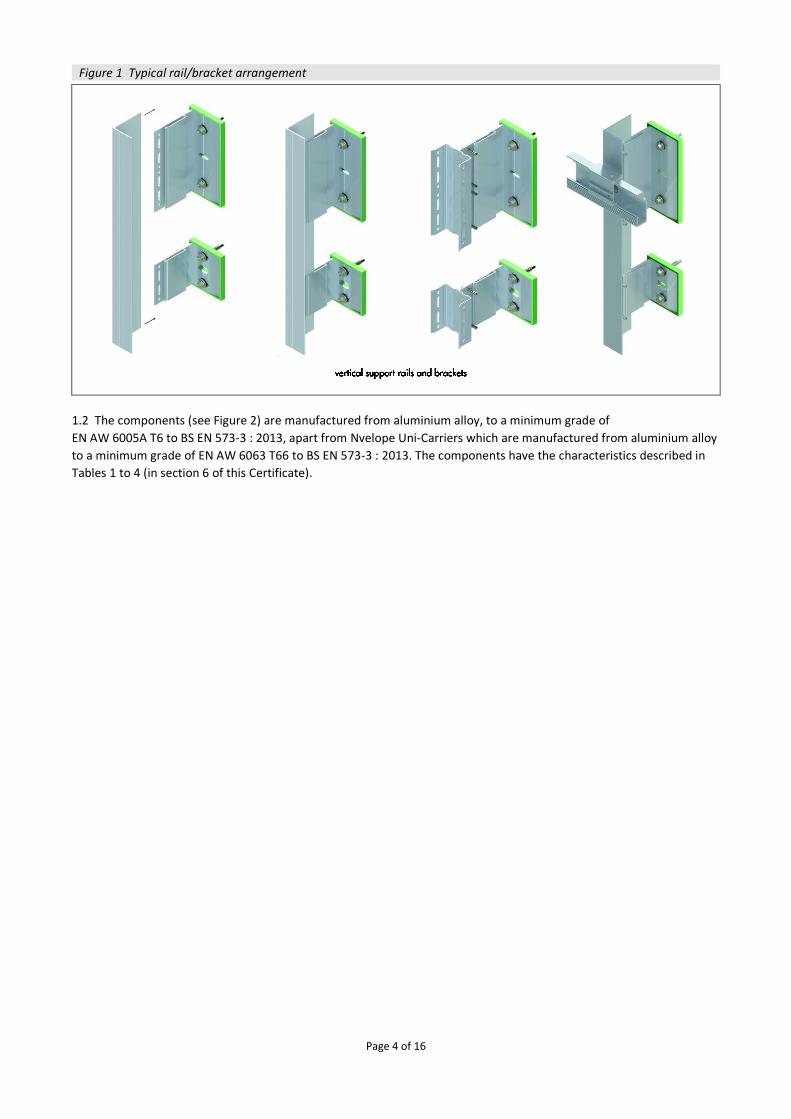
1.1 Nvelope Rainscreen Cladding Support Systems are attached to the external or internal wall structure of buildings
(see Figure 1) and consist of:
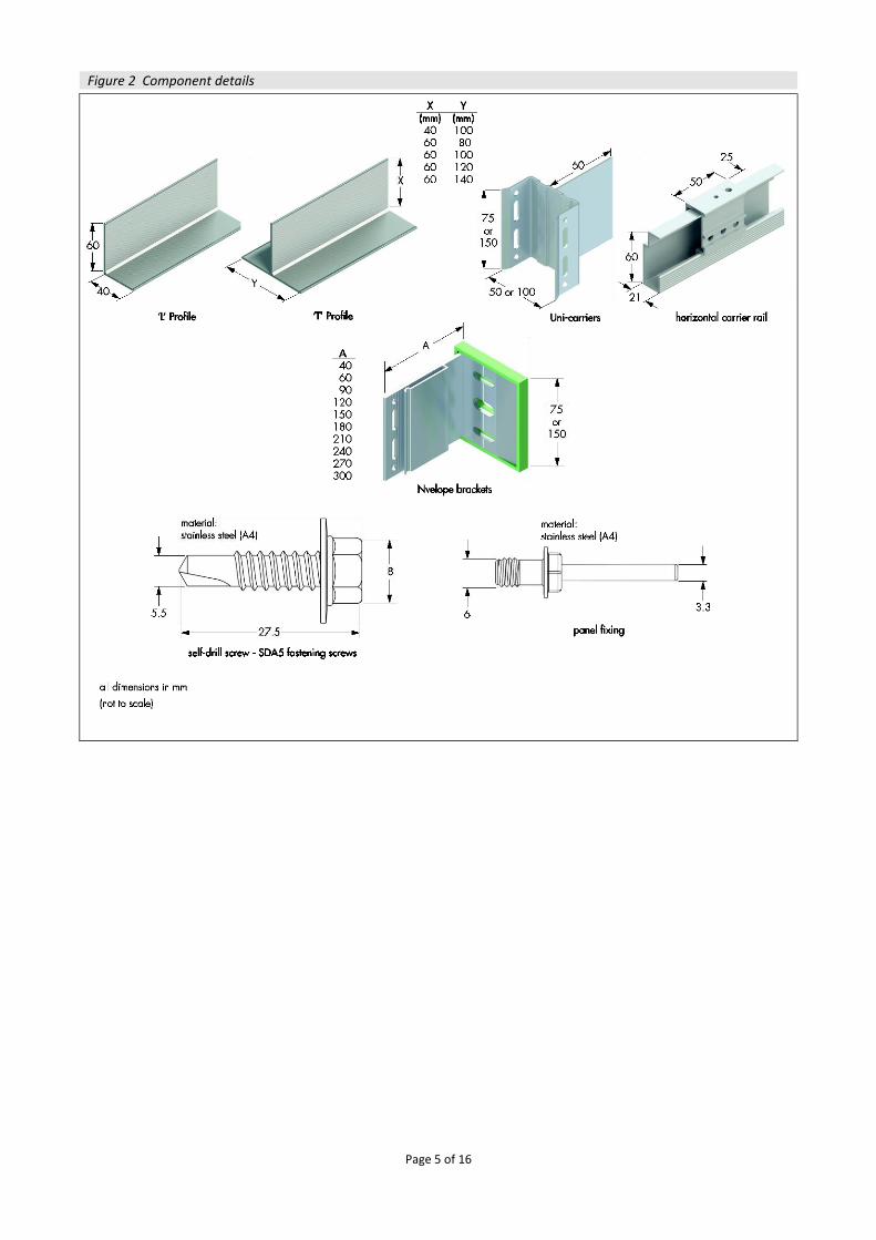
NV Brackets — fitted to the substrate using appropriate fixings (outside the scope of this Certificate). Brackets feature a polypropylene thermal insulation pad (insulating properties outside the scope of this Certificate) fitted to the heel. Two variants of the brackets are available: single and double. The single brackets have a height of 75 mm and the double brackets, 150 mm, both with a thickness range of 2.8 to 5.3 mm
Nvelope Uni-Carriers — vertical ‘U’ section profiles, fixed to the NV Brackets using self-drilling screws (see Figure 2), used to support timber battens to which cladding panels can be fixed. Four variants of carrier are available, with widths of 50 or 100 mm, and heights of 75 or 150 mm
Nvelope L and T Rails — rails of ‘L’ and ‘T’ profile with a 2.2 mm thickness and the dimensions shown in Figure 2, fixed to the NV Brackets using self-drilling screws, which provide a fixing area for the cladding panels
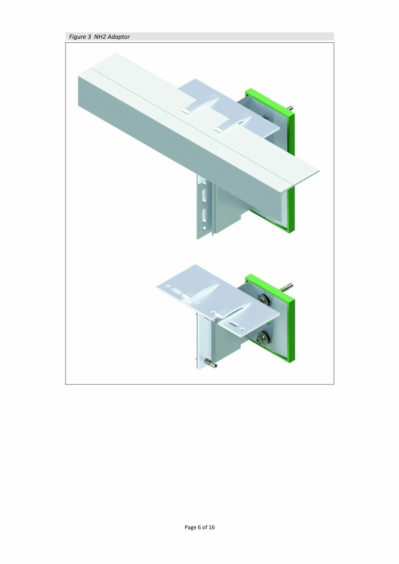
NH2 Adaptor — an adaptor, slotted upright into the vertical bracket, with the adaptor ‘helping hands’ orientated over the top of the vertical bracket (see Figure 3). The ‘helping hands’ of the adaptor are then ready to receive an L or T rail in the horizontal orientation
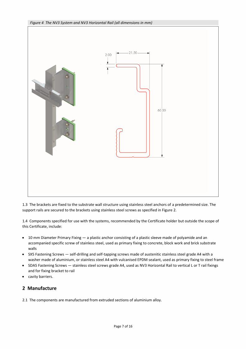
the NV3 System — consisting of the NV3 Horizontal Rail and the associated hanger components (NV3 TUFS Hangers), and with details as shown in Figure 4.
Page 4 of 16
Figure 1 Typical rail/bracket arrangement
1.2 The components (see Figure 2) are manufactured from aluminium alloy, to a minimum grade of
EN AW 6005A T6 to BS EN 573-3 : 2013, apart from Nvelope Uni-Carriers which are manufactured from aluminium alloy
to a minimum grade of EN AW 6063 T66 to BS EN 573-3 : 2013. The components have the characteristics described in
Tables 1 to 4 (in section 6 of this Certificate).
Page 5 of 16
Figure 2 Component details
Page 6 of 16
Figure 3 NH2 Adaptor
Page 7 of 16
Figure 4 The NV3 System and NV3 Horizontal Rail (all dimensions in mm)
1.3 The brackets are fixed to the substrate wall structure using stainless steel anchors of a predetermined size. The
support rails are secured to the brackets using stainless steel screws as specified in Figure 2.
1.4 Components specified for use with the systems, recommended by the Certificate holder but outside the scope of
this Certificate, include:
10 mm Diameter Primary Fixing — a plastic anchor consisting of a plastic sleeve made of polyamide and an
accompanied specific screw of stainless steel, used as primary fixing to concrete, block work and brick substrate
walls
SX5 Fastening Screws — self-drilling and self-tapping screws made of austenitic stainless steel grade A4 with a
washer made of aluminium, or stainless steel A4 with vulcanised EPDM sealant, used as primary fixing to steel frame
SDA5 Fastening Screws — stainless steel screws grade A4, used as NV3 Horizontal Rail to vertical L or T rail fixings
and for fixing bracket to rail
cavity barriers.
2 Manufacture
2.1 The components are manufactured from extruded sections of aluminium alloy.
Page 8 of 16
2.2 As part of the assessment and ongoing surveillance of product quality, the BBA has:
agreed with the manufacturer the quality control procedures and product testing to be undertaken
assessed and agreed the quality control operated over batches of incoming materials
monitored the production process and verified that it is in accordance with the documented process
evaluated the process for management of nonconformities
checked that equipment has been properly tested and calibrated
undertaken to carry out the above measures on a regular basis through a surveillance process, to verify that the
specifications and quality control operated by the manufacturer are being maintained.
3 Delivery and site handling
3.1 The aluminium brackets are wrapped on pallets. Every pallet carries a label bearing the manufacturer’s name and a
label bearing the BBA logo incorporating the number of this Certificate.
3.2 Packs of rails should be stacked horizontally, on sufficient bearers to prevent distortion, to a maximum height of
one metre. Other components should be stored safely until ready for use.
3.3 The pallets should be stored on a dry, flat and level surface, suitably protected from the weather. Ancillary items
should be stored in separate boxes.
3.4 The brackets are delivered to site in cartons of a size suitable for manual handling.
3.5 The systems should be handled with care. Damaged items should be discarded.
3.6 Protective clothing should be worn, as required, and all health and safety regulations observed. Care should be
taken when handling long lengths of rail, especially at height.
Assessment and Technical Investigations The following is a summary of the assessment and technical investigations carried out on Nvelope Rainscreen Cladding
Support Systems.
Design Considerations
4 Use 4.1 Nvelope Rainscreen Cladding Support Systems, when installed in accordance with this Certificate, are satisfactory
for use in back-ventilated and drained cavity rainscreen cladding systems, as well as for internal cladding systems as a
sub-frame to support cladding on the external or internal wall structure, of new and existing buildings.
4.2 The systems are applied to the outside of the external or internal wall structures of new or existing buildings.
Application must be carried out strictly in accordance with this Certificate and the Certificate holder’s instructions, by
installers approved by the Certificate holder.
4.3 The substrate wall to which the systems are to be fixed must be structurally sound, watertight and satisfy the
requirements of the relevant national Building Regulations and Standards with respect to heat and sound transmission.
4.4 It is important for designers, planners, contractors and/or installers to ensure that the systems and the substrate
wall have adequate structural capacity to support cladding panels in accordance with the design and installation
requirements of the cladding panel supplier.
Page 9 of 16
5 Practicability of installation
The systems are designed to be installed by cladding contractors who are suitably qualified. Further advice can be
provided by the Certificate holder.
6 Mechanical resistance and stability
6.1 The substrate wall to which the cladding components are to be fixed should be designed and constructed in accordance with the requirements of the relevant national Building Regulations and Standards.
6.2 Assessment of structural performance of the systems for individual buildings must be carried out by a designer or a suitably qualified and experienced individual to ensure that:
the support systems and cladding to be supported are compatible
any thermal expansion effects of both the support systems and the cladding to be supported are taken into account in the design and detailing.
the specified fixings have adequate tensile and pull-out strength to resist the applied actions
the fixing of the support brackets to the supporting wall has adequate tensile, shear and pull-out strength, and corrosion resistance (outside the scope of this Certificate). An appropriate number of site-specific pull-out tests must be conducted on the substrate wall to determine the minimum pull-out resistance to failure of the fixings. The characteristic pull-out resistance should be determined in accordance with the guidance given in EOTA TR055 : 2016, using 50% of the mean value of the five smallest measured values at the ultimate load.
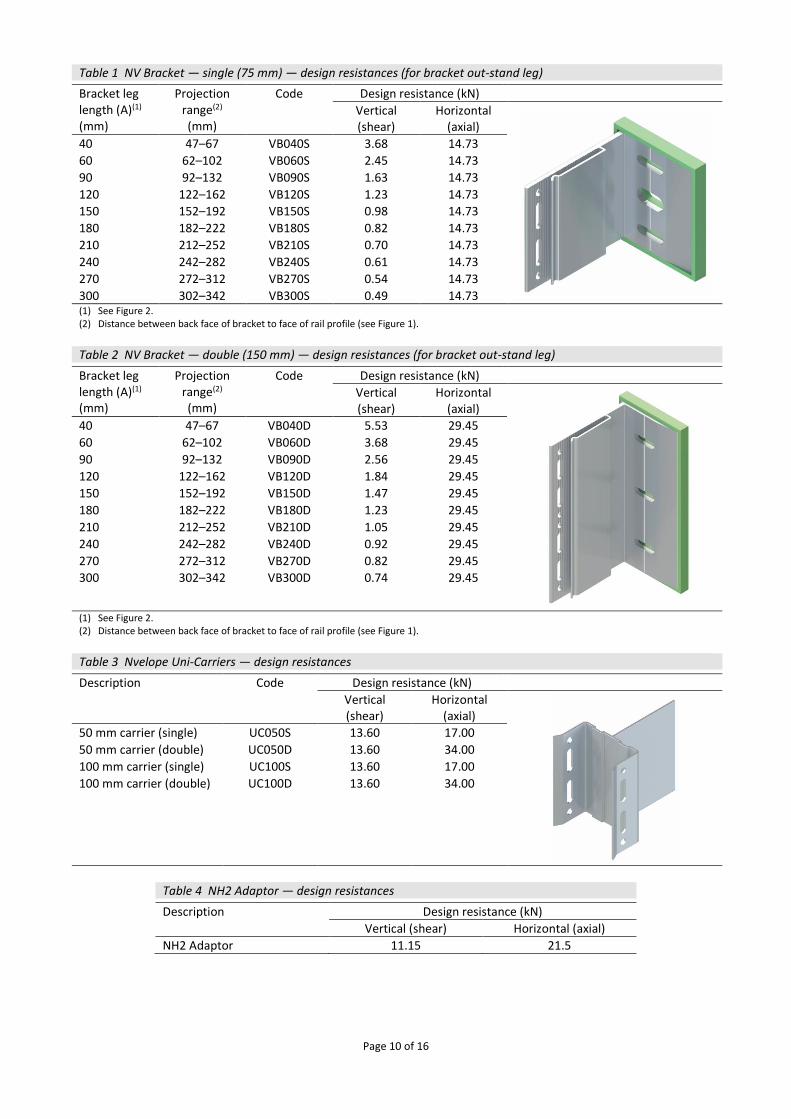
6.3 The supporting wall must be able to resist the gravity load from the self-weight of the cladding, the wind actions and any racking loads, on its own. No contribution from the cladding system may be assumed in this respect. 6.4 The wind loads on the wall should be calculated in accordance with BS EN 1991-1-4 : 2005 and its UK National Annex. Due consideration should be given to the high-pressure coefficients applicable to corners of the building as recommended in this Standard. In accordance with BS EN 1990 : 2002 and its UK National Annex, it is recommended that a partial load factor of 1.5 is used to determine the ultimate wind load to be resisted by the systems. 6.5 A combination of horizontal and vertical actions must be checked by an appropriately qualified design engineer, in accordance with BS EN 1999-1-1 : 2007 and BS EN 1999-1-3 : 2007, and their UK National Annexes, in conjunction with BS EN 1990 : 2002 and all relevant standard parts and its corresponding UK National Annex. 6.6 Details of the brackets, NH2 Adaptor and Uni-Carriers, with their design loadbearing resistances, are shown in Tables 1, 2, 3 and 4. The design loadbearing resistance of the connections should be greater than that of the bracket and adaptor as tabulated.
Page 10 of 16
Table 1 NV Bracket — single (75 mm) — design resistances (for bracket out-stand leg)
Bracket leg length (A)(1)
(mm)
Projection range(2) (mm)
Code Design resistance (kN)
Vertical (shear)
Horizontal (axial)
40 47–67 VB040S 3.68 14.73
60 62–102 VB060S 2.45 14.73
90 92–132 VB090S 1.63 14.73
120 122–162 VB120S 1.23 14.73
150 152–192 VB150S 0.98 14.73
180 182–222 VB180S 0.82 14.73
210 212–252 VB210S 0.70 14.73
240 242–282 VB240S 0.61 14.73
270 272–312 VB270S 0.54 14.73
300 302–342 VB300S 0.49 14.73 (1) See Figure 2. (2) Distance between back face of bracket to face of rail profile (see Figure 1).
Table 2 NV Bracket — double (150 mm) — design resistances (for bracket out-stand leg)
Bracket leg length (A)(1)
(mm)
Projection range(2) (mm)
Code Design resistance (kN)
Vertical (shear)
Horizontal (axial)
40 47–67 VB040D 5.53 29.45
60 62–102 VB060D 3.68 29.45
90 92–132 VB090D 2.56 29.45
120 122–162 VB120D 1.84 29.45
150 152–192 VB150D 1.47 29.45
180 182–222 VB180D 1.23 29.45
210 212–252 VB210D 1.05 29.45
240 242–282 VB240D 0.92 29.45
270 272–312 VB270D 0.82 29.45
300 302–342 VB300D 0.74 29.45
(1) See Figure 2. (2) Distance between back face of bracket to face of rail profile (see Figure 1).
Table 3 Nvelope Uni-Carriers — design resistances
Description Code Design resistance (kN)
Vertical (shear)
Horizontal (axial)
50 mm carrier (single) UC050S 13.60 17.00
50 mm carrier (double) UC050D 13.60 34.00
100 mm carrier (single) UC100S 13.60 17.00
100 mm carrier (double) UC100D 13.60 34.00
Table 4 NH2 Adaptor — design resistances
Description Design resistance (kN)
Vertical (shear) Horizontal (axial)
NH2 Adaptor 11.15 21.5
Page 11 of 16
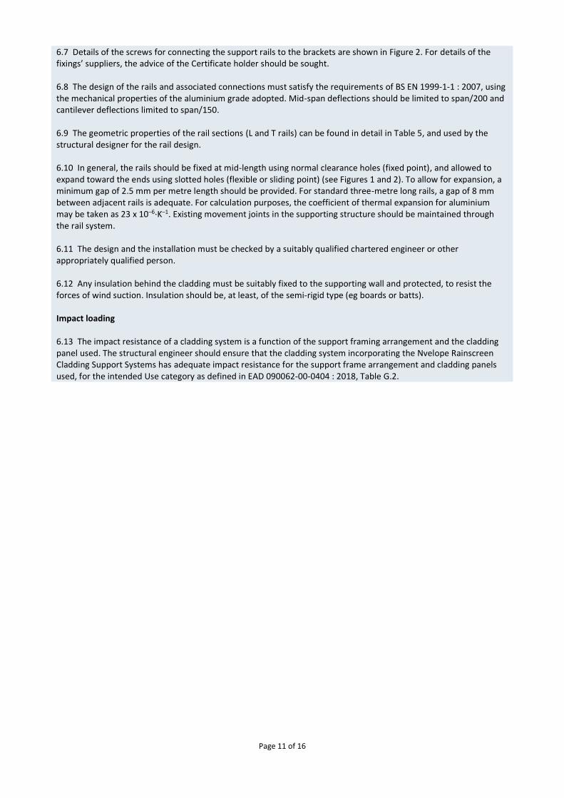
6.7 Details of the screws for connecting the support rails to the brackets are shown in Figure 2. For details of the fixings’ suppliers, the advice of the Certificate holder should be sought. 6.8 The design of the rails and associated connections must satisfy the requirements of BS EN 1999-1-1 : 2007, using the mechanical properties of the aluminium grade adopted. Mid-span deflections should be limited to span/200 and cantilever deflections limited to span/150. 6.9 The geometric properties of the rail sections (L and T rails) can be found in detail in Table 5, and used by the structural designer for the rail design. 6.10 In general, the rails should be fixed at mid-length using normal clearance holes (fixed point), and allowed to expand toward the ends using slotted holes (flexible or sliding point) (see Figures 1 and 2). To allow for expansion, a minimum gap of 2.5 mm per metre length should be provided. For standard three-metre long rails, a gap of 8 mm between adjacent rails is adequate. For calculation purposes, the coefficient of thermal expansion for aluminium may be taken as 23 x 10–6·K–1. Existing movement joints in the supporting structure should be maintained through the rail system. 6.11 The design and the installation must be checked by a suitably qualified chartered engineer or other appropriately qualified person. 6.12 Any insulation behind the cladding must be suitably fixed to the supporting wall and protected, to resist the forces of wind suction. Insulation should be, at least, of the semi-rigid type (eg boards or batts). Impact loading 6.13 The impact resistance of a cladding system is a function of the support framing arrangement and the cladding panel used. The structural engineer should ensure that the cladding system incorporating the Nvelope Rainscreen Cladding Support Systems has adequate impact resistance for the support frame arrangement and cladding panels used, for the intended Use category as defined in EAD 090062-00-0404 : 2018, Table G.2.
Page 12 of 16
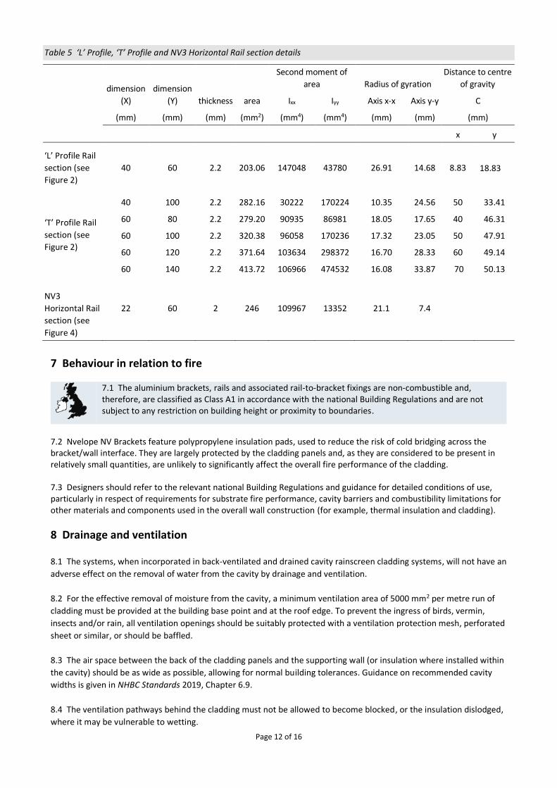
Table 5 ‘L’ Profile, ‘T’ Profile and NV3 Horizontal Rail section details
dimension
(X)
dimension
(Y) thickness area
Second moment of
area Radius of gyration
Distance to centre
of gravity
Ixx Iyy Axis x-x Axis y-y C
(mm) (mm) (mm) (mm2) (mm4) (mm4) (mm) (mm) (mm)
x y
‘L’ Profile Rail
section (see
Figure 2)
40 60 2.2 203.06 147048 43780 26.91 14.68 8.83 18.83
‘T’ Profile Rail
section (see
Figure 2)
40 100 2.2 282.16 30222 170224 10.35 24.56 50 33.41
60 80 2.2 279.20 90935 86981 18.05 17.65 40 46.31
60 100 2.2 320.38 96058 170236 17.32 23.05 50 47.91
60 120 2.2 371.64 103634 298372 16.70 28.33 60 49.14
60 140 2.2 413.72 106966 474532 16.08 33.87 70 50.13
NV3
Horizontal Rail
section (see
Figure 4)
22 60 2 246 109967 13352 21.1 7.4
7 Behaviour in relation to fire
7.1 The aluminium brackets, rails and associated rail-to-bracket fixings are non-combustible and, therefore, are classified as Class A1 in accordance with the national Building Regulations and are not subject to any restriction on building height or proximity to boundaries.
7.2 Nvelope NV Brackets feature polypropylene insulation pads, used to reduce the risk of cold bridging across the bracket/wall interface. They are largely protected by the cladding panels and, as they are considered to be present in relatively small quantities, are unlikely to significantly affect the overall fire performance of the cladding. 7.3 Designers should refer to the relevant national Building Regulations and guidance for detailed conditions of use, particularly in respect of requirements for substrate fire performance, cavity barriers and combustibility limitations for other materials and components used in the overall wall construction (for example, thermal insulation and cladding).
8 Drainage and ventilation
8.1 The systems, when incorporated in back-ventilated and drained cavity rainscreen cladding systems, will not have an
adverse effect on the removal of water from the cavity by drainage and ventilation.
8.2 For the effective removal of moisture from the cavity, a minimum ventilation area of 5000 mm2 per metre run of
cladding must be provided at the building base point and at the roof edge. To prevent the ingress of birds, vermin,
insects and/or rain, all ventilation openings should be suitably protected with a ventilation protection mesh, perforated
sheet or similar, or should be baffled.
8.3 The air space between the back of the cladding panels and the supporting wall (or insulation where installed within
the cavity) should be as wide as possible, allowing for normal building tolerances. Guidance on recommended cavity
widths is given in NHBC Standards 2019, Chapter 6.9.
8.4 The ventilation pathways behind the cladding must not be allowed to become blocked, or the insulation dislodged,
where it may be vulnerable to wetting.
Page 13 of 16
8.5 As the aluminium is sourced from naturally occurring ores, the components are non-toxic during fabrication and in
normal use and, as they are non-combustible, do not produce toxic effects when exposed to fire.
9 Maintenance The systems are confined behind the cladding panels and do not require special maintenance.
10 Durability
10.1 The systems, when used as prescribed in this Certificate, can be expected to have a service life in excess of 35 years in normal UK conditions.
10.2 Unprotected aluminium interacts with cement-based materials, resulting in severe corrosion. Therefore,
aluminium brackets should be used with polypropylene isolator pads (which are supplied with the brackets), when
brackets are used in masonry walls.
11 Reuse and recyclability
The components contain polypropylene and aluminium, which can be recycled.
Installation
12 General 12.1 The systems must be installed in accordance with the manufacturer’s recommendations, the requirements of this
Certificate and any specifications laid down by the project consulting engineer or designer.
12.2 The Certificate holder can provide technical assistance at the design stage, and installation assistance at the start
of the installation.
13 Procedure 13.1 Based on a preliminary survey of the wall and architectural/structural design, a grid layout for the sub-frame is
first prepared.
13.2 The brackets (with the isolator pad) are fixed to the substrate wall using stainless steel fixings of an appropriate
size as determined by design (see sections 1.4 and 6.4).
13.3 The rails are inserted into the brackets and, after adjustment for line and level, fixed to the brackets using self-
drilling stainless steel screws, as determined by design.
13.4 The rails are normally attached to the substrate wall to span one storey height. They are normally anchored at
mid-span using the round holes on the brackets (fixed point/dead loads), and allowed to expand at the ends using the
elongated holes on the brackets (flexible point).
13.5 Where specified, insulation should be tightly butted around the brackets and secured to the substrate wall using
the appropriate fixings.
13.6 Where required to protect the substrate wall or insulation from wind-driven rain, an appropriate vapour
permeable membrane should be applied to the surface.
13.7 Cladding panels (outside the scope of this Certificate) deemed to be compatible with the systems are
appropriately fixed to the vertical rails.
Page 14 of 16
Technical Investigations
14 Investigations
14.1 The manufacturing process was evaluated, including the methods adopted for quality control, and details were
obtained of the quality and composition of the materials used.
14.2 An assessment was made of the systems’ resistance to wind loading based on calculations to BS EN 1999-1-3:
2007, durability and behaviour in relation to fire.
14.3 Based on a user survey, an assessment was made of the systems’ practicability of installation and performance in
use.
Page 15 of 16
Bibliography BS EN 573-3 : 2013 Aluminium and aluminium alloys — Chemical composition and form of wrought products — Part 3: Chemical composition and form of products BS EN 1990 : 2002 + A1: 2005 Eurocode — Basis of structural design NA to BS EN 1990 : 2002 + A1 : 2005 UK National Annex for Eurocode — Basis of structural design BS EN 1991-1-4 : 2005 + A1 : 2010 Eurocode 1: Actions on structures — General actions — Wind actions NA to BS EN 1991-1-4 : 2005 + A1 : 2010 UK National Annex to Eurocode 1 — Actions on structures — General actions — Wind actions BS EN 1999-1-1 : 2007 Eurocode 9 Design of aluminium structures — General structural rules NA to BS EN 1999-1-1 : 2007 + A1 : 2009 UK National Annex to Eurocode 9 — Design of aluminium structures — General structural rules BS EN 1999-1-3 : 2007 + A1: 2011 Eurocode 9 — Design of aluminium structures — Structures susceptible to fatigue NA to BS EN 1999-1-3 : 2007 + A1 : 2011 UK National Annex to Eurocode 9 — Design of aluminium structures —Structures susceptible to fatigue EAD 090062-00-0404 : 2018 – Kits for external wall claddings mechanically fixed EOTA TR055 : 2016 Design of fasteners based on EAD 330232-00-0601
Page 16 of 16
Conditions of Certification
15 Conditions 15.1 This Certificate:
relates only to the product/system that is named and described on the front page
is issued only to the company, firm, organisation or person named on the front page – no other company, firm, organisation or person may hold or claim that this Certificate has been issued to them
is valid only within the UK
has to be read, considered and used as a whole document – it may be misleading and will be incomplete to be selective
is copyright of the BBA
is subject to English Law. 15.2 Publications, documents, specifications, legislation, regulations, standards and the like referenced in this Certificate are those that were current and/or deemed relevant by the BBA at the date of issue or reissue of this Certificate. 15.3 This Certificate will remain valid for an unlimited period provided that the product/system and its manufacture and/or fabrication, including all related and relevant parts and processes thereof:
are maintained at or above the levels which have been assessed and found to be satisfactory by the BBA
continue to be checked as and when deemed appropriate by the BBA under arrangements that it will determine
are reviewed by the BBA as and when it considers appropriate. 15.4 The BBA has used due skill, care and diligence in preparing this Certificate, but no warranty is provided. 15.5 In issuing this Certificate the BBA is not responsible and is excluded from any liability to any company, firm, organisation or person, for any matters arising directly or indirectly from:
the presence or absence of any patent, intellectual property or similar rights subsisting in the product/system or any other product/system
the right of the Certificate holder to manufacture, supply, install, maintain or market the product/system
actual installations of the product/system, including their nature, design, methods, performance, workmanship and maintenance
any works and constructions in which the product/system is installed, including their nature, design, methods, performance, workmanship and maintenance
any loss or damage, including personal injury, howsoever caused by the product/system, including its manufacture, supply, installation, use, maintenance and removal
any claims by the manufacturer relating to CE marking. 15.6 Any information relating to the manufacture, supply, installation, use, maintenance and removal of this product/system which is contained or referred to in this Certificate is the minimum required to be met when the product/system is manufactured, supplied, installed, used, maintained and removed. It does not purport in any way to restate the requirements of the Health and Safety at Work etc. Act 1974, or of any other statutory, common law or other duty which may exist at the date of issue or reissue of this Certificate; nor is conformity with such information to be taken as satisfying the requirements of the 1974 Act or of any statutory, common law or other duty of care.
British Board of Agrément Bucknalls Lane Watford Herts WD25 9BA
©2019
tel: 01923 665300
[email protected] www.bbacerts.co.uk