agreement addendum 116: regulation no. 117 · tyres of class c1 with regard to adhesion performance...
TRANSCRIPT
GE.11-
Agreement
Concerning the adoption of uniform technical prescriptions for wheeled vehicles, equipment and parts which can be fitted and/or be used on wheeled vehicles and the conditions for reciprocal recognition of approvals granted on the basis of these prescriptions*
(Revision 2, including the amendments which entered into force on 16 October 1995)
Addendum 116: Regulation No. 117
Revision 2
Incorporating all valid text up to:
Corrigendum 1 to the Revision 1 - Erratum
Corrigendum 2 to the 01 series - Date of entry into force: 25 June 2008
Corrigendum 3 to the 01 series - Date of entry into force: 10 March 2009
02 series of amendments - Date of entry into force: 30 January 2011
Corrigendum 1 to the 02 series of amendments - Date of entry into force: 30 January 2011
Corrigendum 2 to the 02 series of amendments - Date of entry into force: 22 June 2011
Corrigendum 3 to the 02 series of amendments - Date of entry into force: 22 June 2011
Uniform Provisions concerning the Approval of Tyres with regard to Rolling Sound Emissions and to Adhesion on Wet Surfaces and/or to Rolling Resistance
UNITED NATIONS
* Former title of the Agreement: Agreement Concerning the Adoption of Uniform Conditions of Approval and Reciprocal Recognition
of Approval for Motor Vehicle Equipment and Parts, done at Geneva on 20 March 1958.
E/ECE/324/Rev.2/Add.116/Rev.2−E/ECE/TRANS/505/Rev.2/Add.116/Rev.2
15 September 2011

E/ECE/324/Rev.2/Add.116/Rev.2 E/ECE/TRANS/505/Rev.2/Add.116/Rev.2
3
Regulation No. 117
Uniform provisions concerning the approval of tyres with regard to rolling sound emissions and to adhesion on wet surfaces and/or to rolling resistance
Contents Page
1. Scope ....................................................................................................................................... 5
2. Definitions ............................................................................................................................... 5
3. Application for approval ......................................................................................................... 9
4. Markings ................................................................................................................................. 10
5. Approval .................................................................................................................................. 11
6. Specifications .......................................................................................................................... 14
7. Modifications of the type of pneumatic tyre and extension of approval ................................. 17
8. Conformity of production ........................................................................................................ 18
9. Penalties for non-conformity of production ............................................................................ 19
10. Production definitely discontinued .......................................................................................... 19
11. Names and addresses of Technical Services responsible for conducting approval tests, and of Type Approval Authority ............................................................................................. 19
12. Transitional provisions ............................................................................................................ 19
Annexes
1. Communication concerning the approval or extension or refusal or withdrawal of approval or production definitely discontinued of a type of tyre with regard to "rolling sound emission level" and "adhesion performance on wet surfaces" and/or to "rolling resistance" pursuant to Regulation No. 117 ................................................ 21
2. Example of Approval Marks
Appendix 1: Arrangements of Approval Marks - Approval according to Regulation No. 117 .......................................................................................... 23
Appendix 2: Approval according to Regulation No. 117 coincident with approval to Regulation No. 30 or 54 ................................................................................... 24
Appendix 3: Extensions to combine approvals issued in accordance with Regulations Nos. 117, 30 or 54 ........................................................................ 27
Appendix 4: Extensions to combine approvals issued in accordance with Regulation No. 117 .......................................................................................... 29
3. Coast-by test method for measuring tyre-rolling sound emission ........................................... 31
Appendix 1: Test report ........................................................................................................ 39
4. Specifications for the test site .................................................................................................. 41

E/ECE/324/Rev.2/Add.116/Rev.2 E/ECE/TRANS/505/Rev.2/Add.116/Rev.2
4
5. Test procedure for measuring wet grip .................................................................................... 49
Appendix 1: Test report (Adhesion on wet surface) ............................................................. 56
6. Test procedure for measuring rolling resistance ...................................................................... 58
Appendix 1: Test equipment tolerances ................................................................................ 68
Appendix 2: Measuring rim width ........................................................................................ 71
Appendix 3: Test report and Test data (Rolling resistance) .................................................. 73
7. Procedures for snow performance testing ............................................................................... 74
Appendix 1: Pictogram definition of "Alpine Symbol" ........................................................ 78
Appendix 2: Test reports and Test data ................................................................................ 79
E/ECE/324/Rev.2/Add.116/Rev.2 E/ECE/TRANS/505/Rev.2/Add.116/Rev.2
5
1. Scope
1.1. This Regulation applies to new pneumatic tyres of Classes C1, C2 and C3 with regard to their sound emissions, rolling resistance and to new pneumatic tyres of Class C1 with regard to adhesion performance on wet surfaces (wet adhesion). It does not, however, apply to:
1.1.1. Tyres designed as "Temporary use spare tyres" and marked "Temporary use only";
1.1.2. Tyres having a nominal rim diameter code ≤ 10 (or ≤ 254 mm) or ≥ 25 (or ≥ 635 mm);
1.1.3. Tyres designed for competitions;
1.1.4. Tyres intended to be fitted to road vehicles of categories other than M, N and O1;
1.1.5. Tyres fitted with additional devices to improve traction properties (e.g. studded tyres);
1.1.6. Tyres with a speed rating less than 80 km/h (speed symbol F);
1.1.7. Tyres designed only to be fitted to vehicles registered for the first time before 1 October 1990.
1.1.8. Professional off-road tyres for the requirements on rolling resistance and rolling sound.
1.2. Contracting Parties shall issue or accept approvals to rolling sound and/or wet adhesion and/or rolling resistance.
2. Definitions
For the purpose of this Regulation, in addition to the definitions contained in Regulations Nos. 30 and 54, the following definitions apply.
2.1. "Type of tyre" means, in relation to this Regulation, a range of tyres consisting of a list of tyre size designations, brand names and trade descriptions, which do not differ in such essential characteristics as:
(a) The manufacturer's name;
(b) The tyre class (see paragraph 2.4.);
(c) The tyre structure;
(d) The category of use: normal tyre, snow tyre and special use tyre;
(e) For Class C1 tyres:
(i) In case of tyres submitted for approval of rolling sound emission levels, whether normal or reinforced (or extra load);
(ii) In case of tyres submitted for approval of performance adhesion on wet surfaces, whether normal tyres or snow tyres
1 As defined in the Consolidated Resolution on the Construction of Vehicles (R.E.3), document ECE/TRANS/WP.29/78/Rev.2, para. 2.
E/ECE/324/Rev.2/Add.116/Rev.2 E/ECE/TRANS/505/Rev.2/Add.116/Rev.2
6
with a speed category of Q or below excluding H (≤ 160 km/h) or speed category R and above including H (> 160 km/h);
(f) For Class C2 and C3 tyres:
(i) In case of tyres submitted for approval of rolling sound emission levels at stage 1, whether M+S marked or not;
(ii) In case of tyres submitted for approval of rolling sound emission levels at stage 2, whether traction tyre or not;
(g) The tread pattern (see paragraph 3.2.1.).
2.2. "Brand name" or "Trade description" means the identification of the tyre as given by the tyre manufacturer. The Brand name may be the same as that of the manufacturer and the Trade description may coincide with the trade mark.
2.3. "Rolling sound emission" means the sound emitted from the contact between the tyres in motion and the road surface.
2.4. "Tyre Class" means one of the following groupings:
2.4.1. Class C1 tyres: Tyres conforming to Regulation No. 30;
2.4.2. Class C2 tyres: Tyres conforming to Regulation No. 54 and identified by a load capacity index in single formation lower or equal to 121 and a speed category symbol higher or equal to "N";
2.4.3. Class C3 tyres: Tyres conforming to Regulation No. 54 and identified by:
(a) A load capacity index in single formation higher or equal to 122; or
(b) A load capacity index in single formation lower or equal to 121 and a speed category symbol lower or equal to "M".
2.5. "Representative tyre size" means the tyre size which is submitted to the test described in Annex 3 to this Regulation with regard to rolling sound emissions, or Annex 5 for adhesion on wet surfaces or Annex 6 for rolling resistance to assess the conformity for the Type Approval of the type of tyre, or Annex 7 for snow performance to assess the category of use "snow".
2.6. "Temporary-use spare tyre" means a tyre different from a tyre intended to be fitted to any vehicle for normal driving conditions; but intended only for temporary use under restricted driving conditions.
2.7. "Tyres designed for competition" means tyres intended to be fitted to vehicles involved in motor sport competition and not intended for non-competitive on-road use.
2.8. "Normal tyre" means a tyre intended for normal on-road use.
2.9. "Reinforced tyre" or "extra load tyre" of Class C1 means a pneumatic-tyre structure designed to carry more load at a higher inflation pressure than the load carried by the corresponding standard version tyre at the standard inflation pressure as specified in ISO 4000-1:20102.
2.10. "Traction tyre" means a tyre in class C2 or C3 bearing the inscription TRACTION and intended to be fitted primarily to the drive axle(s) of a vehicle to maximize force transmission in various circumstances.
2 Class C1 tyres correspond "passenger car tyres" in ISO 4000-1:2010.
E/ECE/324/Rev.2/Add.116/Rev.2 E/ECE/TRANS/505/Rev.2/Add.116/Rev.2
7
2.11. "Snow tyre" means a tyre whose tread pattern, tread compound or structure are primarily designed to achieve in snow conditions a performance better than that of a normal tyre with regard to its ability to initiate, maintain or stop vehicle motion.
2.12. "Special use tyre" means a tyre intended for mixed use both on- and off-road or for other special duty. These tyres are primarily designed to initiate and maintain the vehicle in motion in off-road conditions.
2.13. "Professional off-road tyre" is a special use tyre primarily used for service in severe off-road conditions.
2.14. "Tread depth" means the depth of the principal grooves.
2.14.1. "Principal grooves" means the wide circumferential grooves positioned in the central zone of the tyre tread, which, in the case of passenger and light truck (commercial) tyres, have the treadwear indicators located in the base.
2.15. "Void to fill ratio" means the ratio between the area of voids in a reference surface and the area of this reference surface calculated from the mould drawing.
2.16. "Standard reference test tyre" (SRTT) means a tyre that is produced, controlled and stored in accordance with the ASTM (American Society for Testing and Materials) standards E1136-93 (2003) (size P195/75R14).
2.17. Wet Grip measurements - Specific definitions
2.17.1. "Adhesion on wet surfaces" means the relative braking performance, on a wet surface, of a test vehicle equipped with the candidate tyre in comparison to that of the same test vehicle equipped with a reference tyre (SRTT).
2.17.2. "Candidate tyre" means a tyre, representative of the type that is submitted for approval in accordance with this Regulation.
2.17.3. "Control tyre" means a normal production tyre that is used to establish the wet grip performance of tyre sizes unable to be fitted to the same vehicle as the standard reference test tyre - see paragraph 2.2.2.16. of Annex 5 to this Regulation.
2.17.4. "Wet grip index ("G")" means the ratio between the performance of the candidate tyre and the performance of the standard reference test tyre.
2.17.5. "Peak brake force coefficient ("pbfc")" means the maximum value of the ratio of braking force to vertical load on the tyre prior to wheel lock-up.
2.17.6. "Mean fully developed deceleration ("mfdd")" means the average deceleration calculated on the basis of the measured distance recorded when decelerating a vehicle between two specified speeds.
2.17.7. "Coupling (hitch) height" means the height when measured perpendicularly from the centre of the articulation point of the trailer towing coupling or hitch to the ground, when the towing vehicle and trailer are coupled together. The vehicle and trailer shall be standing on level pavement surface in its test mode complete with the appropriate tyre(s) to be used in the particular test.
2.18. Rolling resistance measurement - Specific definitions
2.18.1. Rolling resistance Fr
E/ECE/324/Rev.2/Add.116/Rev.2 E/ECE/TRANS/505/Rev.2/Add.116/Rev.2
8
Loss of energy (or energy consumed) per unit of distance traveled3.
2.18.2. Rolling resistance coefficient Cr
Ratio of the rolling resistance to the load on the tyre4.
2.18.3. New test tyre
A tyre which has not been previously used in a rolling deflected test that raises its temperature above that generated in rolling resistance tests, and which has not previously been exposed to a temperature above 40 °C5, 6.
2.18.4. Laboratory Control Tyre
Tyre used by an individual laboratory to control machine behaviour as a function of time7.
2.18.5. Capped inflation
Process of inflating the tyre and allowing the inflation pressure to build up, as the tyre is warmed up while running.
2.18.6. Parasitic loss
Loss of energy (or energy consumed) per unit distance excluding internal tyre losses, attributable to aerodynamic loss of the different rotating elements of the test equipment, bearing friction and other sources of systematic loss which may be inherent in the measurement.
2.18.7. Skim test reading
Type of parasitic loss measurement, in which the tyre is kept rolling without slippage, while reducing the tyre load to a level at which energy loss within the tyre itself is virtually zero.
2.18.8. Inertia or Moment of Inertia.
Ratio of the torque applied to a rotating body to the rotational acceleration of this body8.
3 The International System of Units (SI) unit conventionally used for the rolling resistance is the newton-meter per meter, which is equivalent to a drag force in newton.
4 The rolling resistance is expressed in newton and the load is expressed in kilo-newton. The rolling resistance coefficient is dimensionless.
5 New test tyre definition is needed to reduce potential data variation and dispersion due to tyre aging effects.
6 It is permissible to repeat an accepted test procedure. 7 An example of machine behaviour is drift. 8 The rotating body can be, for example, a tyre assembly or machine drum.
E/ECE/324/Rev.2/Add.116/Rev.2 E/ECE/TRANS/505/Rev.2/Add.116/Rev.2
9
2.18.9. Measurement reproducibility σm
Capability of a machine to measure rolling resistance9.
3. Application for approval
3.1. The application for approval of a type of tyre with regard to this Regulation shall be submitted by the tyre manufacturer or by his duly accredited representative. It shall specify:
3.1.1. The performance characteristics to be assessed for the tyre type; "rolling sound emissions level" and/or "adhesion performance level on wet surfaces" and/or "rolling resistance level". Tyre "snow performance level" in cases where the category of use is snow;
3.1.2. Name of manufacturer;
3.1.3. Name and address of applicant;
3.1.4. Address(es) of manufacturing plant(s);
3.1.5. Brand name(s), trade description(s), trade mark(s);
3.1.6. Tyre class (Class C1, C2 or C3) (see paragraph 2.4. of this Regulation);
3.1.6.1. Section width range for class C1 tyres (see paragraph 6.1.1. of this Regulation);
Note: This information is required only for approval with regard to rolling sound emission level.
3.1.7. Tyre structure;
3.1.8. For Class C1 tyres, state whether:
(a) Reinforced (or extra load) in case of approval with regard to rolling sound emission level;
(b) Speed category symbol "Q" or below (excluding "H") or "R" and above (including "H") in case of "snow" tyres for approval with regard to adhesion on wet surfaces;
For Class C2 and C3 tyres, state whether:
(a) M+S marked in case of approval with regard to rolling sound emission level at stage 1;
(b) Traction in case of approval with regard to rolling sound emission level at stage 2.
9 Measurement reproducibility σm shall be estimated by measuring n times (where n ≥ 3), on a single tyre, the whole procedure described in paragraph 4. of Annex 6 as follows:
∑ ∑= =
⋅−⋅
−=
n
j
n
jjjm Cr
nCr
n1
2
1
1
1
1σ
Where: j = is the counter from 1 to n for the number of repetitions of each measurement for a given tyre, n = number of repetitions of tyre measurements (n ≥ 3).
E/ECE/324/Rev.2/Add.116/Rev.2 E/ECE/TRANS/505/Rev.2/Add.116/Rev.2
10
3.1.9. Category of use (normal, snow, or special);
3.1.10. A list of tyre size designations covered by this application.
3.2. The application for approval shall be accompanied (in triplicate) by:
3.2.1. Details of the major features, with respect to the effects on the performance (i.e. rolling sound emission level, adhesion on wet surfaces, rolling resistance and snow grip) of the tyres, including the tread pattern, included in the designated range of tyre sizes. This may be by means of descriptions supplemented by technical data, drawings, photographs and Computer Tomography (CT), and must be sufficient to allow the Type Approval Authority or technical service to determine whether any subsequent changes to the major features will adversely affect the tyre performance. The effects of changes to minor details of tyre construction on tyre performances will be evident and determined during checks on conformity of production;
3.2.2. Drawings or photographs of the tyre sidewall, showing the information given in paragraph 3.1.8. above and the approval marking referred to in paragraph 4., shall be submitted once the production has been established, but no later than one year after the date of granting of Type Approval.
3.2.3. In the case of applications relating to special use tyres, a copy of the mould drawing of the tread pattern shall be supplied in order to allow verification of the void-to-fill ratio.
3.3. At the request of the Type Approval Authority, the applicant shall submit samples of tyres for test or copies of test reports from the technical services, communicated as given in paragraph 11 of this Regulation.
3.4. With regard to the application, testing may be confined to a worst case selection, at the discretion of the Type Approval Authority or designated technical service.
3.5. The laboratories and test facilities of a tyre manufacturer may be designated as an approved laboratory and the Type Approval Authority shall have the option of being represented during any tests.
4. Markings
4.1. All tyres constituting the type of tyre shall be marked as prescribed by either Regulation No. 30 or 54, as applicable.
4.2. In particular tyres shall bear10:
4.2.1. The manufacturer's name or trade mark;
4.2.2. The trade description (see paragraph 2.2.). However, the trade description is not required when it coincides with the trade mark;
4.2.3. The tyre size designation;
4.2.4. The inscription "REINFORCED" (or alternatively "EXTRA LOAD") if the tyre is classified as reinforced;
10 Some of these requirements may be specified separately in Regulation No. 30 or 54.
E/ECE/324/Rev.2/Add.116/Rev.2 E/ECE/TRANS/505/Rev.2/Add.116/Rev.2
11
4.2.5. The inscription "TRACTION" if the tyre is classified as traction11;
4.2.6. The inscription "M+S" or "M.S" or "M&S" in the case of a tyre designed to ensure in mud and fresh or melting snow a performance better than that of a normal tyre.
4.2.7. The "Alpine" symbol ("3-peak-mountain with snowflake" see Annex 7 Appendix 1) for all categories if the tyre is classified in the category of use "snow".
4.2.8. The inscription "MPT" (or alternatively "ML" or "ET") and /or "POR" if the tyre is classified in the category of use "special".
ET means Extra Tread, ML stands for Mining and Logging, MPT means Multi-Purpose Truck and POR means Professional Off-Road.
4.3. Tyres shall provide adequate space for the approval mark as shown in Annex 2 to this Regulation.
4.4. The approval mark shall be moulded into or onto the sidewall of the tyre, shall be clearly legible and shall be located in the lower area of the tyre on at least one of the sidewalls.
4.4.1. However, in the case of tyres identified by the tyre to rim fitment configuration symbol "A", the marking may be located anywhere on the outside sidewall of the tyre.
5. Approval
5.1. If the representative tyre size of the type of tyre submitted for approval pursuant to this Regulation meets the requirements of paragraphs 6 and 7. below, approval of that type of tyre shall be granted.
5.2. An approval number shall be assigned to the type of tyre approved. The same Contracting Party may not assign the same number to another type of tyre.
5.3. Notice of approval or extension of approval or refusal of approval of a type of tyre pursuant to this Regulation shall be communicated to the Parties to the Agreement, which apply this Regulation by means of a form conforming to the model in Annex 1 to the Regulation.
5.3.1. Tyre manufacturers are entitled to submit an application for extension of Type Approval to the requirements of other Regulations relevant to the tyre type. In that case, a copy of the relevant Type Approval communication(s), as issued by the relevant Type Approval Authority, shall be attached to the application for extension of approval. All applications for extension of approval(s) shall only be granted by the Type Approval Authority which issued the original approval for the tyre.
5.3.1.1. When extension of approval is granted to incorporate into the communication form (see Annex 1 to this Regulation) certification(s) of conformity to other Regulations, the approval number on the communication form shall be supplemented by suffix(es) to identify the given Regulation(s) and the technical prescriptions which have been incorporated by the extension of approval. In relation to each given suffix, the specific Type Approval
11 Minimum height of marking: refer to dimension C in Annex 3 of Regulation No. 54.
E/ECE/324/Rev.2/Add.116/Rev.2 E/ECE/TRANS/505/Rev.2/Add.116/Rev.2
12
number(s) and the Regulation itself shall be added to paragraph 9. of the communication form.
5.3.1.2. The prefix shall identify the series of amendments of the prescription on tyre performances for the relevant Regulation, e.g. 02S2 to identify the second series of amendments on tyre road rolling sound emissions at stage 2 or 02S1WR1 to identify the second series of amendments on tyre road rolling sound emissions at stage 1, tyre adhesion on wet surfaces and rolling resistance at stage 1 (see paragraph 6.1. for stage 1 and stage 2 definitions). No identification to the series of amendments shall be required if the relevant Regulation is in its original form.
5.3.2. The following suffixes have been already reserved to identify specific Regulations on tyre performance parameters:
S To identify additional conformity to the requirements on tyre rolling sound emissions;
W To identify additional conformity to the requirements on tyre adhesion on wet surfaces;
R To identify additional conformity to the requirements on tyre rolling resistance.
Taking into account that two stages are defined for rolling sound and rolling resistance specifications in paragraphs 6.1. and 6.3., S and R will be followed either by the suffix "1" for compliance to stage 1 or by the suffix "2" for compliance to stage 2.
5.4. In the space referred to in paragraph 4.3. and in accordance with the requirements of paragraph 4.4. there shall be affixed to every tyre size, conforming to the type of tyre approved under this Regulation, an international approval mark consisting of:
E/ECE/324/Rev.2/Add.116/Rev.2 E/ECE/TRANS/505/Rev.2/Add.116/Rev.2
13
5.4.1. A circle surrounding the letter "E" followed by the distinguishing number of the country which has granted approval12;; and
5.4.2. The approval number, which shall be placed close to the circle prescribed in paragraph 5.4.1. either above or below the "E" or to the left or right of that letter.
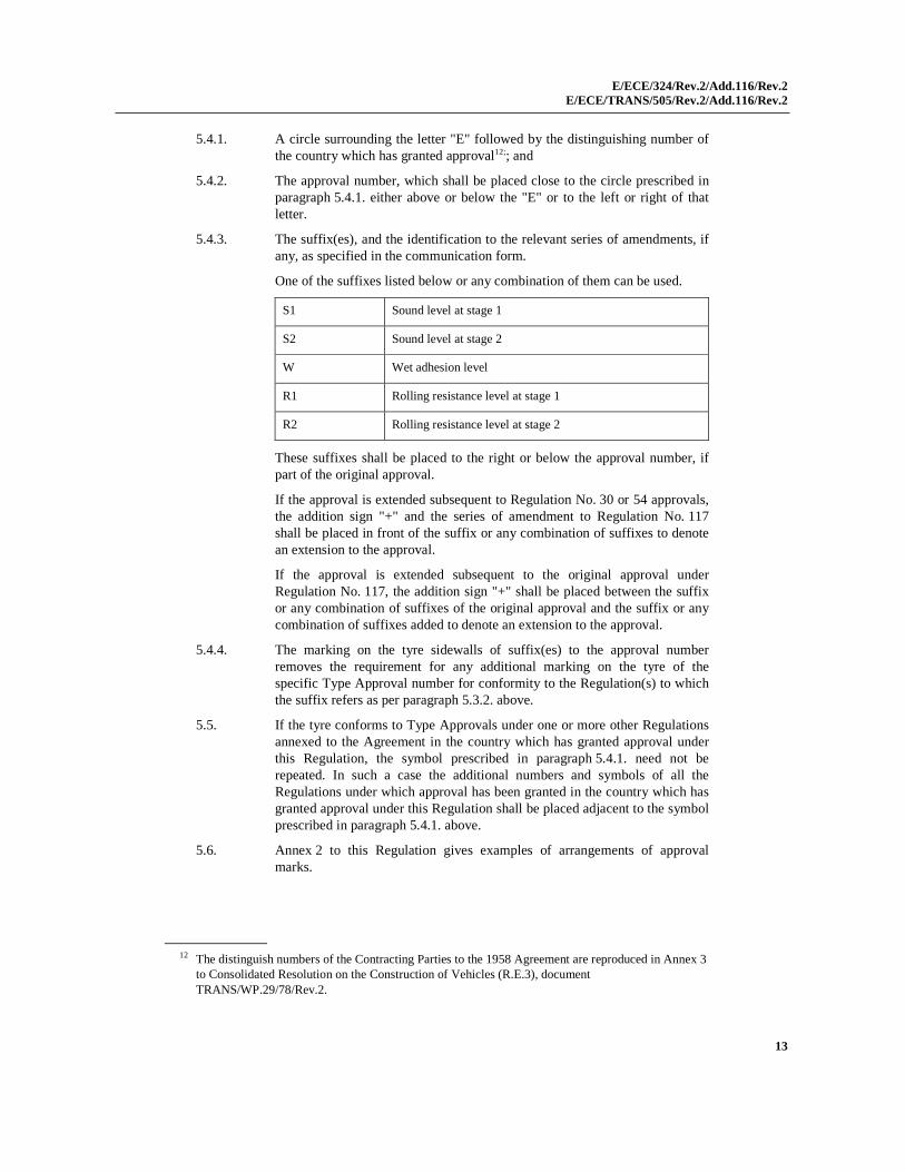
5.4.3. The suffix(es), and the identification to the relevant series of amendments, if any, as specified in the communication form.
One of the suffixes listed below or any combination of them can be used.
S1 Sound level at stage 1
S2 Sound level at stage 2
W Wet adhesion level
R1 Rolling resistance level at stage 1
R2 Rolling resistance level at stage 2
These suffixes shall be placed to the right or below the approval number, if part of the original approval.
If the approval is extended subsequent to Regulation No. 30 or 54 approvals, the addition sign "+" and the series of amendment to Regulation No. 117 shall be placed in front of the suffix or any combination of suffixes to denote an extension to the approval.
If the approval is extended subsequent to the original approval under Regulation No. 117, the addition sign "+" shall be placed between the suffix or any combination of suffixes of the original approval and the suffix or any combination of suffixes added to denote an extension to the approval.
5.4.4. The marking on the tyre sidewalls of suffix(es) to the approval number removes the requirement for any additional marking on the tyre of the specific Type Approval number for conformity to the Regulation(s) to which the suffix refers as per paragraph 5.3.2. above.
5.5. If the tyre conforms to Type Approvals under one or more other Regulations annexed to the Agreement in the country which has granted approval under this Regulation, the symbol prescribed in paragraph 5.4.1. need not be repeated. In such a case the additional numbers and symbols of all the Regulations under which approval has been granted in the country which has granted approval under this Regulation shall be placed adjacent to the symbol prescribed in paragraph 5.4.1. above.
5.6. Annex 2 to this Regulation gives examples of arrangements of approval marks.
12 The distinguish numbers of the Contracting Parties to the 1958 Agreement are reproduced in Annex 3 to Consolidated Resolution on the Construction of Vehicles (R.E.3), document TRANS/WP.29/78/Rev.2.
E/ECE/324/Rev.2/Add.116/Rev.2 E/ECE/TRANS/505/Rev.2/Add.116/Rev.2
14
6. Specifications
6.1. Rolling sound emission limits, as measured by the method described in Annex 3 to this Regulation.
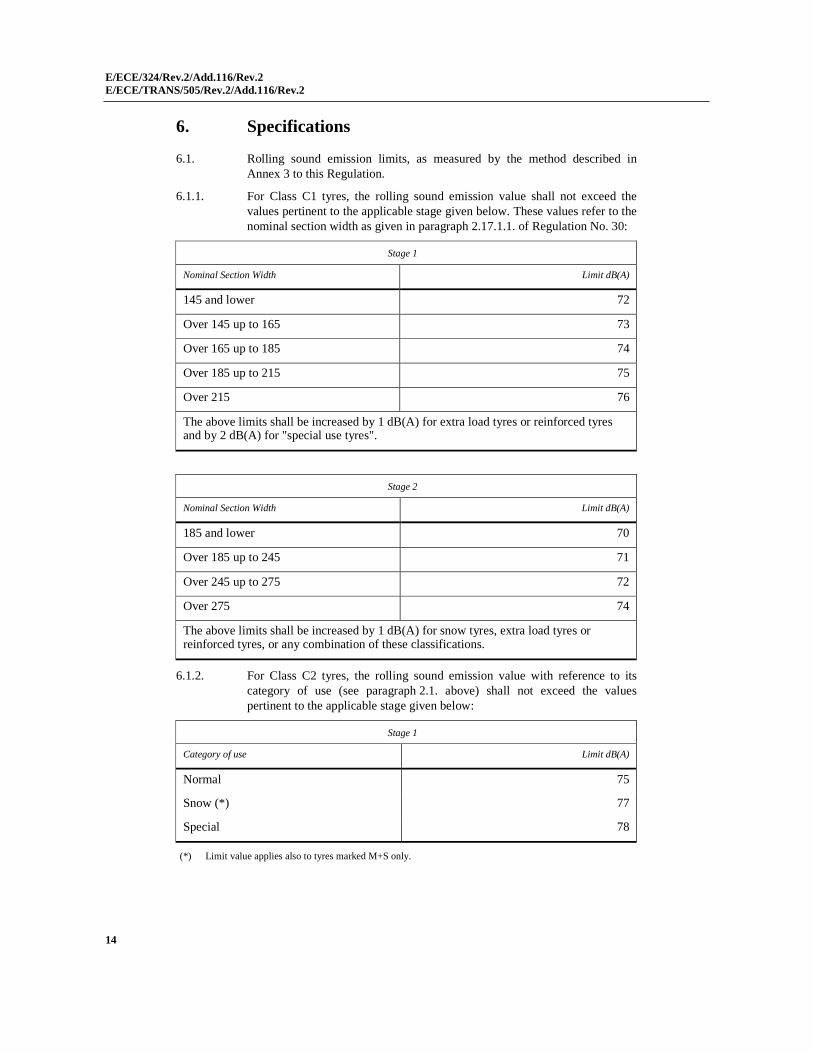
6.1.1. For Class C1 tyres, the rolling sound emission value shall not exceed the values pertinent to the applicable stage given below. These values refer to the nominal section width as given in paragraph 2.17.1.1. of Regulation No. 30:
Stage 1
Nominal Section Width Limit dB(A)
145 and lower 72
Over 145 up to 165 73
Over 165 up to 185 74
Over 185 up to 215 75
Over 215 76
The above limits shall be increased by 1 dB(A) for extra load tyres or reinforced tyres and by 2 dB(A) for "special use tyres".
Stage 2
Nominal Section Width Limit dB(A)
185 and lower 70
Over 185 up to 245 71
Over 245 up to 275 72
Over 275 74
The above limits shall be increased by 1 dB(A) for snow tyres, extra load tyres or reinforced tyres, or any combination of these classifications.
6.1.2. For Class C2 tyres, the rolling sound emission value with reference to its category of use (see paragraph 2.1. above) shall not exceed the values pertinent to the applicable stage given below:
Stage 1
Category of use Limit dB(A)
Normal 75
Snow (*) 77
Special 78
(*) Limit value applies also to tyres marked M+S only.
E/ECE/324/Rev.2/Add.116/Rev.2 E/ECE/TRANS/505/Rev.2/Add.116/Rev.2
15
Stage 2
Category of use Limit dB(A)
Normal 72
Snow 73
Special 74
In case of traction tyres, the above limits shall be increased by 1 dB(A) for category of use normal and special, and by 2 dB(A) for category of use snow.
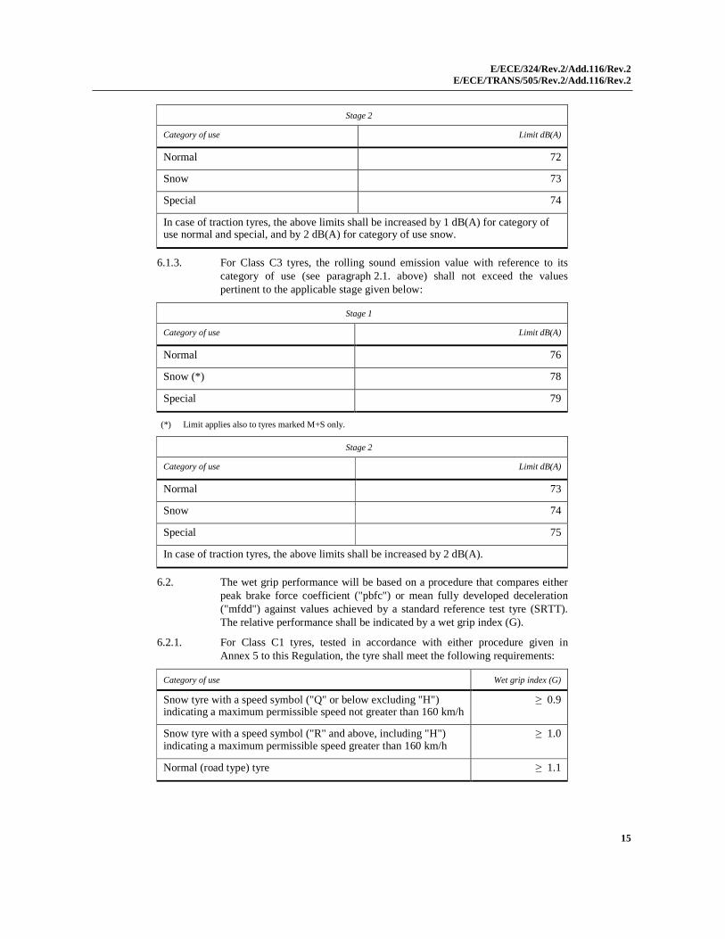
6.1.3. For Class C3 tyres, the rolling sound emission value with reference to its category of use (see paragraph 2.1. above) shall not exceed the values pertinent to the applicable stage given below:
Stage 1
Category of use Limit dB(A)
Normal 76
Snow (*) 78
Special 79
(*) Limit applies also to tyres marked M+S only.
Stage 2
Category of use Limit dB(A)
Normal 73
Snow 74
Special 75
In case of traction tyres, the above limits shall be increased by 2 dB(A).
6.2. The wet grip performance will be based on a procedure that compares either peak brake force coefficient ("pbfc") or mean fully developed deceleration ("mfdd") against values achieved by a standard reference test tyre (SRTT). The relative performance shall be indicated by a wet grip index (G).
6.2.1. For Class C1 tyres, tested in accordance with either procedure given in Annex 5 to this Regulation, the tyre shall meet the following requirements:
Category of use Wet grip index (G)
Snow tyre with a speed symbol ("Q" or below excluding "H") indicating a maximum permissible speed not greater than 160 km/h
≥ 0.9
Snow tyre with a speed symbol ("R" and above, including "H") indicating a maximum permissible speed greater than 160 km/h
≥ 1.0
Normal (road type) tyre ≥ 1.1
E/ECE/324/Rev.2/Add.116/Rev.2 E/ECE/TRANS/505/Rev.2/Add.116/Rev.2
16
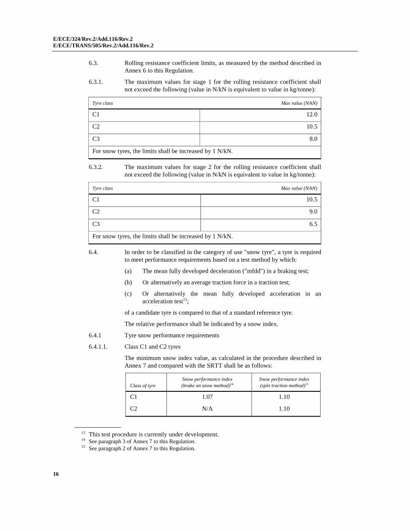
6.3. Rolling resistance coefficient limits, as measured by the method described in Annex 6 to this Regulation.
6.3.1. The maximum values for stage 1 for the rolling resistance coefficient shall not exceed the following (value in N/kN is equivalent to value in kg/tonne):
Tyre class Max value (N/kN)
C1 12.0
C2 10.5
C3 8.0
For snow tyres, the limits shall be increased by 1 N/kN.
6.3.2. The maximum values for stage 2 for the rolling resistance coefficient shall not exceed the following (value in N/kN is equivalent to value in kg/tonne):
Tyre class Max value (N/kN)
C1 10.5
C2 9.0
C3 6.5
For snow tyres, the limits shall be increased by 1 N/kN.
6.4. In order to be classified in the category of use "snow tyre", a tyre is required to meet performance requirements based on a test method by which:
(a) The mean fully developed deceleration ("mfdd") in a braking test;
(b) Or alternatively an average traction force in a traction test;
(c) Or alternatively the mean fully developed acceleration in an acceleration test13;
of a candidate tyre is compared to that of a standard reference tyre.
The relative performance shall be indicated by a snow index.
6.4.1 Tyre snow performance requirements
6.4.1.1. Class C1 and C2 tyres
The minimum snow index value, as calculated in the procedure described in Annex 7 and compared with the SRTT shall be as follows:
Class of tyre Snow performance index (brake on snow method)14
Snow performance index (spin traction method)15
C1 1.07 1.10
C2 N/A 1.10
13 This test procedure is currently under development. 14 See paragraph 3 of Annex 7 to this Regulation. 15 See paragraph 2 of Annex 7 to this Regulation.
E/ECE/324/Rev.2/Add.116/Rev.2 E/ECE/TRANS/505/Rev.2/Add.116/Rev.2
17
6.5. In order to be classified as a "traction tyre", a tyre is required to meet at least one of the conditions of paragraph 6.5.1. below.
6.5.1. The tyre shall have a tread pattern with minimum two circumferential ribs, each containing a minimum of 30 block-like elements, separated by grooves and/or sipe elements the depth of which has to be minimum of one half of the tread depth. The use of an alternative option of a physical test will only apply at a later stage following a further amendment to the Regulation including a reference to an appropriate test methods and limit values.
6.6. In order to be classified as a "special use tyre" a tyre shall have a block tread pattern in which the blocks are larger and more widely spaced than for normal tyres and have the following characteristics:
For C1 tyres: a tread depth ≥ 11 mm and void to fill ratio ≥ 35 per cent
For C2 tyres: a tread depth ≥ 11 mm and void to fill ratio ≥ 35 per cent
For C3 tyres: a tread depth ≥ 16 mm and void to fill ratio ≥ 35 per cent
6.7. In order to be classified as a 'professional off-road tyre', a tyre shall have all of the following characteristics:
(a) For C1 and C2 tyres:
i) A tread depth ≥ 11 mm;
ii) A void-to-fill ratio ≥ 35 per cent;
iii) A maximum speed rating of ≤ Q.
(b) For C3 tyres:
i) A tread depth ≥ 16 mm;
ii) A void-to-fill ratio ≥ 35 per cent;
iii) A maximum speed rating of ≤ K.
7. Modifications of the type of pneumatic tyre and extension of approval
7.1. Every modification of the type of tyre, which may influence the performance characteristics approved in accordance with this Regulation, shall be notified to the Type Approval Authority which approved the type of tyre. The authority may either:
7.1.1. Consider that the modifications are unlikely to have any appreciable adverse effect on the performance characteristics approved and that the tyre will comply with the requirements of this Regulation; or
7.1.2. Require further samples to be submitted for test or further test reports from the designated technical service.
7.1.3. Confirmation or refusal of approval, specifying the modifications, shall be communicated by the procedure given in paragraph 5.3. of this Regulation to the Parties to the Agreement which apply this Regulation.
E/ECE/324/Rev.2/Add.116/Rev.2 E/ECE/TRANS/505/Rev.2/Add.116/Rev.2
18
7.1.4. The Type Approval Authority granting the extension of approval shall assign a series number for such an extension which shall be shown on the communication form.
8. Conformity of production
The conformity of production procedures shall comply with those set out in the Agreement, Appendix 2 (E/ECE/324-E/ECE/TRANS/505/Rev.2) with the following requirements:
8.1. Any tyre approved under this Regulation shall be so manufactured as to conform to the performance characteristics of the type of tyre approved and satisfy the requirements of paragraph 6. above;
8.2. In order to verify conformity as prescribed in paragraph 8.1. above, a random sample of tyres bearing the approval mark required by this Regulation shall be taken from the series production. The normal frequency of verification of conformity of production shall be at least once every two years;
8.2.1. In the case of verifications with regard to approvals in accordance with paragraph 6.2., these shall be carried out using the same procedure (see Annex 5 to this Regulation) as that adopted for original approval, and the Type Approval Authority shall satisfy itself that all tyres falling within an approved type comply with the approval requirement. The assessment shall be based upon the production volume of the tyre type at each manufacturing facility, taking into account the quality management system(s) operated by the manufacturer. Where the test procedure involves testing a number of tyres at the same time, for example a set of four tyres for the purpose of testing wet grip performance in accordance with the standard vehicle procedure given in Annex 5 to this Regulation, then the set shall be considered as being one unit for the purposes of calculating the number of tyres to be tested.
8.3. Production shall be deemed to conform to the requirements of this Regulation if the levels measured comply with the limits prescribed in paragraph 6.1. above, with an additional allowance of + 1 dB(A) for possible mass production variations.
8.4. Production shall be deemed to conform to the requirements of this Regulation if the levels measured comply with the limits prescribed in paragraph 6.3. above, with an additional allowance of + 0.3 N/kN for possible mass production variations.
9. Penalties for non-conformity of production
9.1. The approval granted in respect of a type of tyre pursuant to this Regulation may be withdrawn if the requirements laid down in paragraph 8. above are not complied with, or if any tyre of the type of tyre exceeds the limits given in paragraph 8.3. or 8.4. above.
9.2. If a Party to the Agreement, which applies this Regulation, withdraws an approval, it has previously granted, it shall forthwith notify the other Contracting Parties applying this Regulation by means of a copy of the approval form conforming to the model in Annex 1 to the Regulation.
E/ECE/324/Rev.2/Add.116/Rev.2 E/ECE/TRANS/505/Rev.2/Add.116/Rev.2
19
10. Production definitely discontinued
If the holder of an approval completely ceases to manufacture a type of pneumatic tyre approved in accordance with this Regulation, he shall so inform the authority, which granted the approval. Upon receiving the relevant communication that authority shall inform thereof the other Parties to the 1958 Agreement applying this Regulation by means of a communication form conforming to the model in Annex 1 to this Regulation.
11. Names and addresses of Technical Services responsible for conducting approval tests of Type Approval Authority
The Parties to the Agreement which apply this Regulation shall communicate to the United Nations Secretariat, the names and addresses of the Technical Services conducting approval tests and of the Type Approval Authority which grant approval and to which forms certifying approval or extension of approval or refusal or withdrawal of approval, issued in other countries, are to be sent.
12. Transitional provisions
12.1. As from the date of entry into force of the 02 series of amendments to this Regulation, Contracting Parties applying this Regulation shall not refuse to grant ECE approval under this Regulation for a type of tyre if the tyre complies with the requirements of the 02 series of amendments, including the stage 1 or stage 2 rolling sound requirements set out in paragraphs 6.1.1. to 6.1.3., the requirements for wet grip performance set out in paragraph 6.2.1., and the stage 1 or stage 2 rolling resistance requirements set out in paragraph 6.3.1. or 6.3.2.
12.2. As from 1 November 2012, Contracting Parties applying this Regulation shall refuse to grant ECE approval if the tyre type to be approved does not meet the requirements of this Regulation as amended by the 02 series of amendments, and shall, in addition, refuse to grant ECE approval if the stage 2 rolling sound requirements set out in paragraphs 6.1.1. to 6.1.3., the requirements for wet grip performance set out in paragraph 6.2.1., and the stage 1 rolling resistance requirements set out in paragraph 6.3.1. are not complied with.
12.3. As from 1 November 2014, Contracting Parties applying this Regulation may refuse to allow the sale or entry into service of a tyre which does not meet the requirements of this Regulation as amended by the 02 series, and which does not meet the requirements of this Regulation as amended by the 02 series of amendments including the wet grip performance requirements set out in paragraph 6.2.1.
12.4. As from 1 November 2016, Contracting Parties applying this Regulation shall refuse to grant ECE approval if the tyre type to be approved does not meet the requirements of this Regulation as amended by the 02 series of amendments including the stage 2 rolling resistance requirements set out in paragraph 6.3.2.
E/ECE/324/Rev.2/Add.116/Rev.2 E/ECE/TRANS/505/Rev.2/Add.116/Rev.2
20
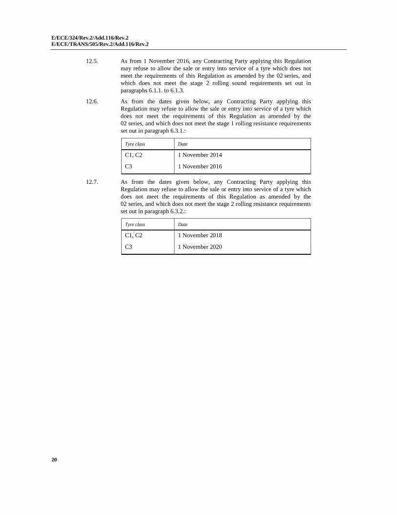
12.5. As from 1 November 2016, any Contracting Party applying this Regulation may refuse to allow the sale or entry into service of a tyre which does not meet the requirements of this Regulation as amended by the 02 series, and which does not meet the stage 2 rolling sound requirements set out in paragraphs 6.1.1. to 6.1.3.
12.6. As from the dates given below, any Contracting Party applying this Regulation may refuse to allow the sale or entry into service of a tyre which does not meet the requirements of this Regulation as amended by the 02 series, and which does not meet the stage 1 rolling resistance requirements set out in paragraph 6.3.1.:
Tyre class Date
C1, C2 1 November 2014
C3 1 November 2016
12.7. As from the dates given below, any Contracting Party applying this Regulation may refuse to allow the sale or entry into service of a tyre which does not meet the requirements of this Regulation as amended by the 02 series, and which does not meet the stage 2 rolling resistance requirements set out in paragraph 6.3.2.:
Tyre class Date
C1, C2 1 November 2018
C3 1 November 2020
E/ECE/324/Rev.2/Add.116/Rev.2 E/ECE/TRANS/505/Rev.2/Add.116/Rev.2
Annex 1
21
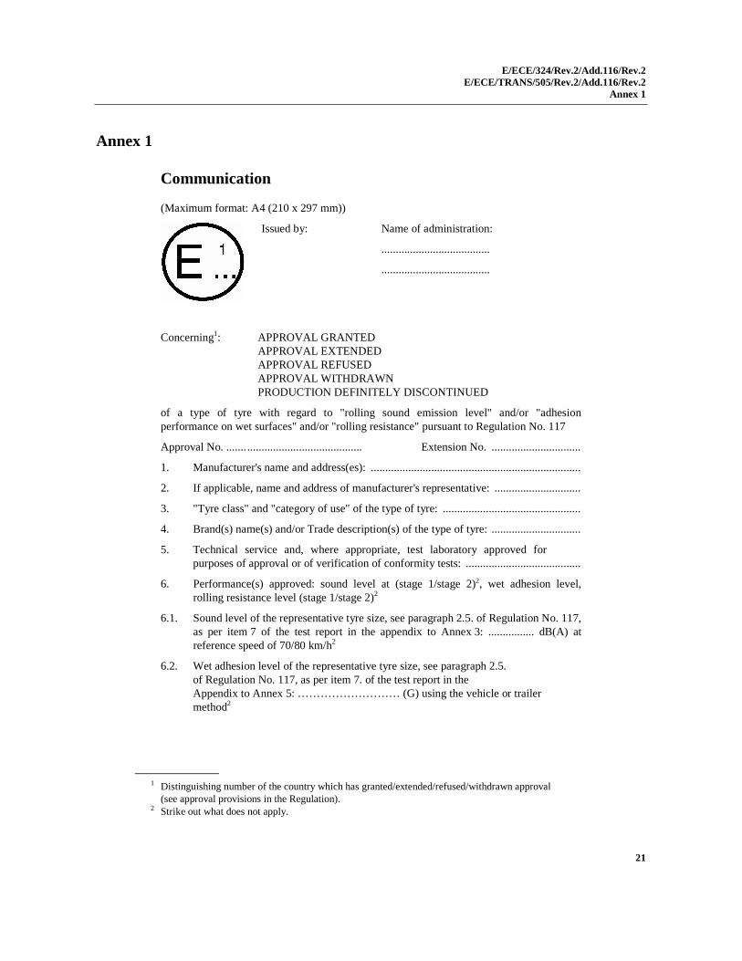
Annex 1
Communication
(Maximum format: A4 (210 x 297 mm))
Issued by: Name of administration:
......................................
......................................
111
Concerning1: APPROVAL GRANTED APPROVAL EXTENDED APPROVAL REFUSED APPROVAL WITHDRAWN PRODUCTION DEFINITELY DISCONTINUED
of a type of tyre with regard to "rolling sound emission level" and/or "adhesion performance on wet surfaces" and/or "rolling resistance" pursuant to Regulation No. 117
Approval No. ....... ........................................ Extension No. ...............................
1. Manufacturer's name and address(es): .........................................................................
2. If applicable, name and address of manufacturer's representative: ..............................
3. "Tyre class" and "category of use" of the type of tyre: ................................................
4. Brand(s) name(s) and/or Trade description(s) of the type of tyre: ...............................
5. Technical service and, where appropriate, test laboratory approved for purposes of approval or of verification of conformity tests: ........................................
6. Performance(s) approved: sound level at (stage 1/stage 2)2, wet adhesion level, rolling resistance level (stage 1/stage 2)2
6.1. Sound level of the representative tyre size, see paragraph 2.5. of Regulation No. 117, as per item 7 of the test report in the appendix to Annex 3: ................ dB(A) at reference speed of 70/80 km/h2
6.2. Wet adhesion level of the representative tyre size, see paragraph 2.5. of Regulation No. 117, as per item 7. of the test report in the Appendix to Annex 5: ……………………… (G) using the vehicle or trailer method2
1 Distinguishing number of the country which has granted/extended/refused/withdrawn approval (see approval provisions in the Regulation).
2 Strike out what does not apply.
E/ECE/324/Rev.2/Add.116/Rev.2 E/ECE/TRANS/505/Rev.2/Add.116/Rev.2 Annexe 1
22
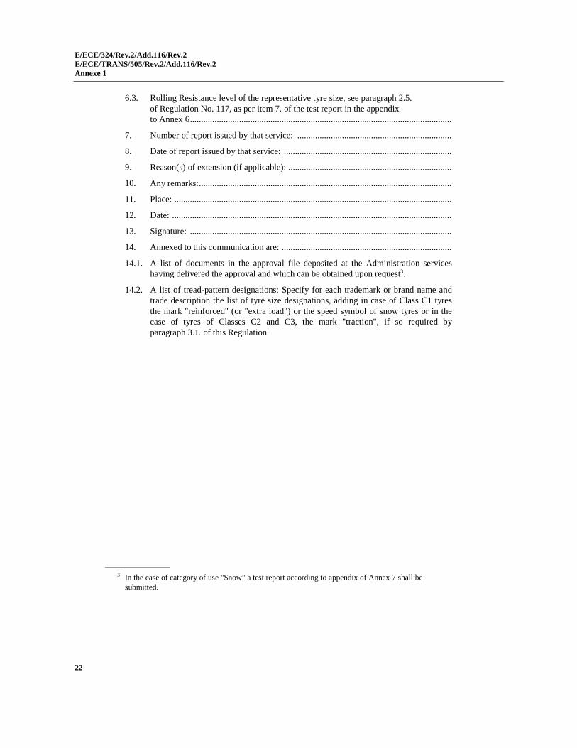
6.3. Rolling Resistance level of the representative tyre size, see paragraph 2.5. of Regulation No. 117, as per item 7. of the test report in the appendix to Annex 6.....................................................................................................................
7. Number of report issued by that service: .....................................................................
8. Date of report issued by that service: ...........................................................................
9. Reason(s) of extension (if applicable): .........................................................................
10. Any remarks:.................................................................................................................
11. Place: ............................................................................................................................
12. Date: .............................................................................................................................
13. Signature: .....................................................................................................................
14. Annexed to this communication are: ............................................................................
14.1. A list of documents in the approval file deposited at the Administration services having delivered the approval and which can be obtained upon request3.
14.2. A list of tread-pattern designations: Specify for each trademark or brand name and trade description the list of tyre size designations, adding in case of Class C1 tyres the mark "reinforced" (or "extra load") or the speed symbol of snow tyres or in the case of tyres of Classes C2 and C3, the mark "traction", if so required by paragraph 3.1. of this Regulation.
3 In the case of category of use "Snow" a test report according to appendix of Annex 7 shall be submitted.
E/ECE/324/Rev.2/Add.116/Rev.2 E/ECE/TRANS/505/Rev.2/Add.116/Rev.2
Annex 2 - Appendix 1
23
Annex 2
Appendix 1
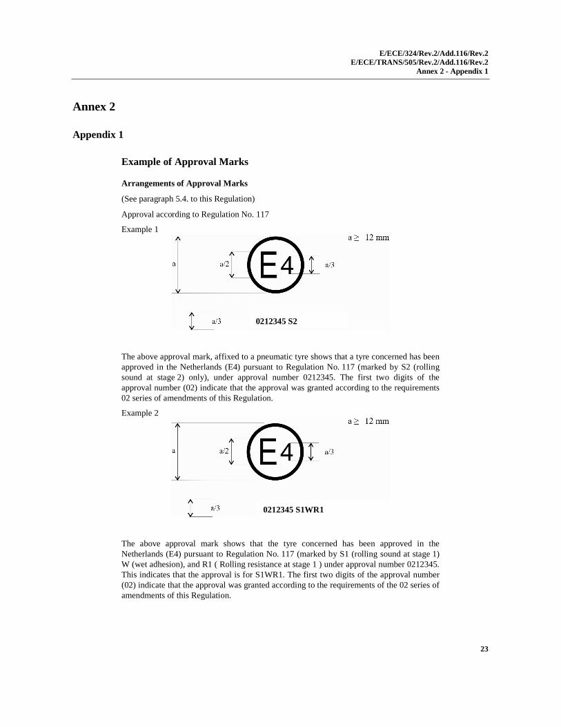
Example of Approval Marks
Arrangements of Approval Marks
(See paragraph 5.4. to this Regulation)
Approval according to Regulation No. 117
Example 1
The above approval mark, affixed to a pneumatic tyre shows that a tyre concerned has been approved in the Netherlands (E4) pursuant to Regulation No. 117 (marked by S2 (rolling sound at stage 2) only), under approval number 0212345. The first two digits of the approval number (02) indicate that the approval was granted according to the requirements 02 series of amendments of this Regulation.
Example 2
The above approval mark shows that the tyre concerned has been approved in the Netherlands (E4) pursuant to Regulation No. 117 (marked by S1 (rolling sound at stage 1) W (wet adhesion), and R1 ( Rolling resistance at stage 1 ) under approval number 0212345. This indicates that the approval is for S1WR1. The first two digits of the approval number (02) indicate that the approval was granted according to the requirements of the 02 series of amendments of this Regulation.
0212345 S2
0212345 S1WR1
E/ECE/324/Rev.2/Add.116/Rev.2 E/ECE/TRANS/505/Rev.2/Add.116/Rev.2 Annexe 2 - Appendix 2
24
Annex 2
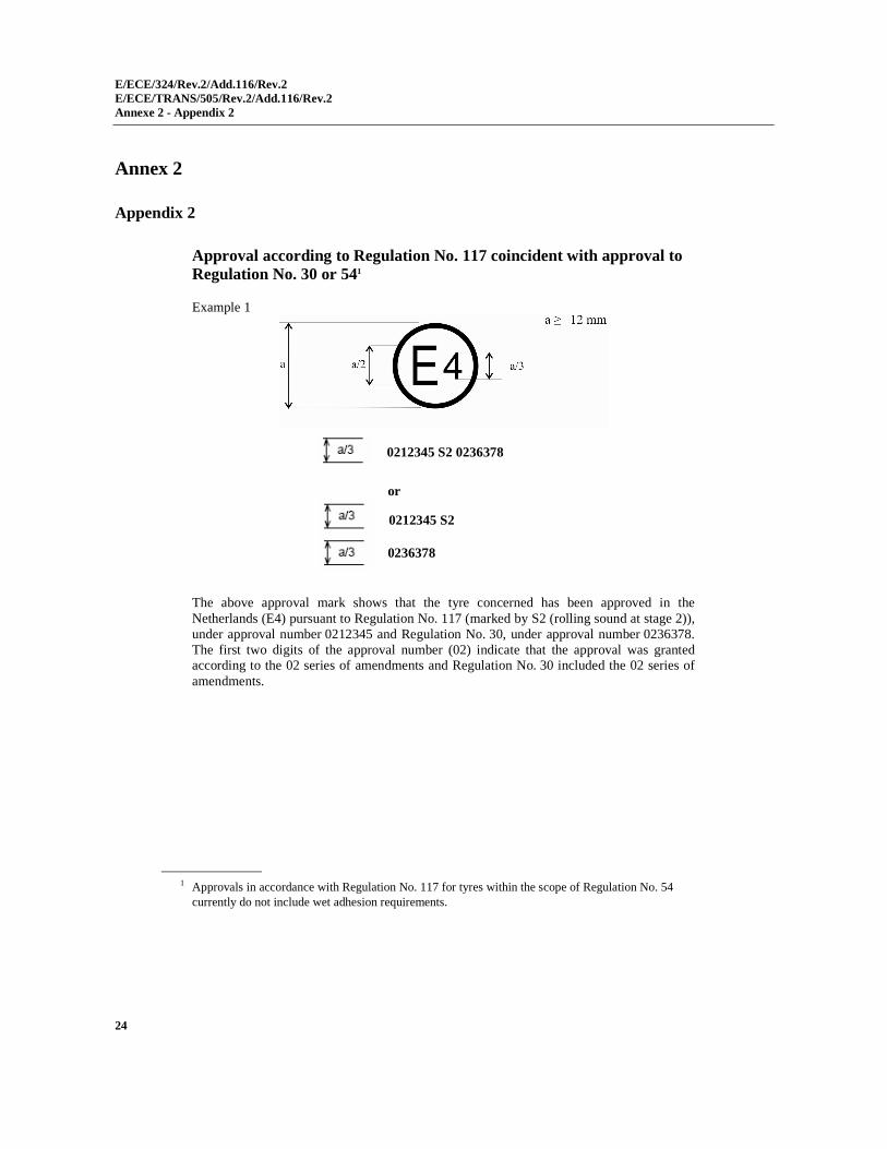
Appendix 2
Approval according to Regulation No. 117 coincident with approval to Regulation No. 30 or 541
Example 1
The above approval mark shows that the tyre concerned has been approved in the Netherlands (E4) pursuant to Regulation No. 117 (marked by S2 (rolling sound at stage 2)), under approval number 0212345 and Regulation No. 30, under approval number 0236378. The first two digits of the approval number (02) indicate that the approval was granted according to the 02 series of amendments and Regulation No. 30 included the 02 series of amendments.
1 Approvals in accordance with Regulation No. 117 for tyres within the scope of Regulation No. 54 currently do not include wet adhesion requirements.
or
0212345 S2 0236378
0212345 S2 0236378
E/ECE/324/Rev.2/Add.116/Rev.2 E/ECE/TRANS/505/Rev.2/Add.116/Rev.2
Annex 2 - Appendix 2
25
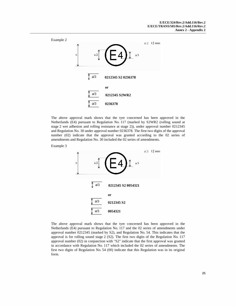
Example 2
The above approval mark shows that the tyre concerned has been approved in the Netherlands (E4) pursuant to Regulation No. 117 (marked by S2WR2 (rolling sound at stage 2 wet adhesion and rolling resistance at stage 2)), under approval number 0212345 and Regulation No. 30 under approval number 0236378. The first two digits of the approval number (02) indicate that the approval was granted according to the 02 series of amendments and Regulation No. 30 included the 02 series of amendments.
Example 3
The above approval mark shows that the tyre concerned has been approved in the Netherlands (E4) pursuant to Regulation No. 117 and the 02 series of amendments under approval number 0212345 (marked by S2), and Regulation No. 54. This indicates that the approval is for rolling sound stage 2 (S2). The first two digits of the Regulation No. 117 approval number (02) in conjunction with "S2" indicate that the first approval was granted in accordance with Regulation No. 117 which included the 02 series of amendments. The first two digits of Regulation No. 54 (00) indicate that this Regulation was in its original form.
or
0212345 S2WR2 0236378
or
0212345 S2 0054321
0212345 S2 0236378
0212345 S2 0054321
E/ECE/324/Rev.2/Add.116/Rev.2 E/ECE/TRANS/505/Rev.2/Add.116/Rev.2 Annexe 2 - Appendix 2
26
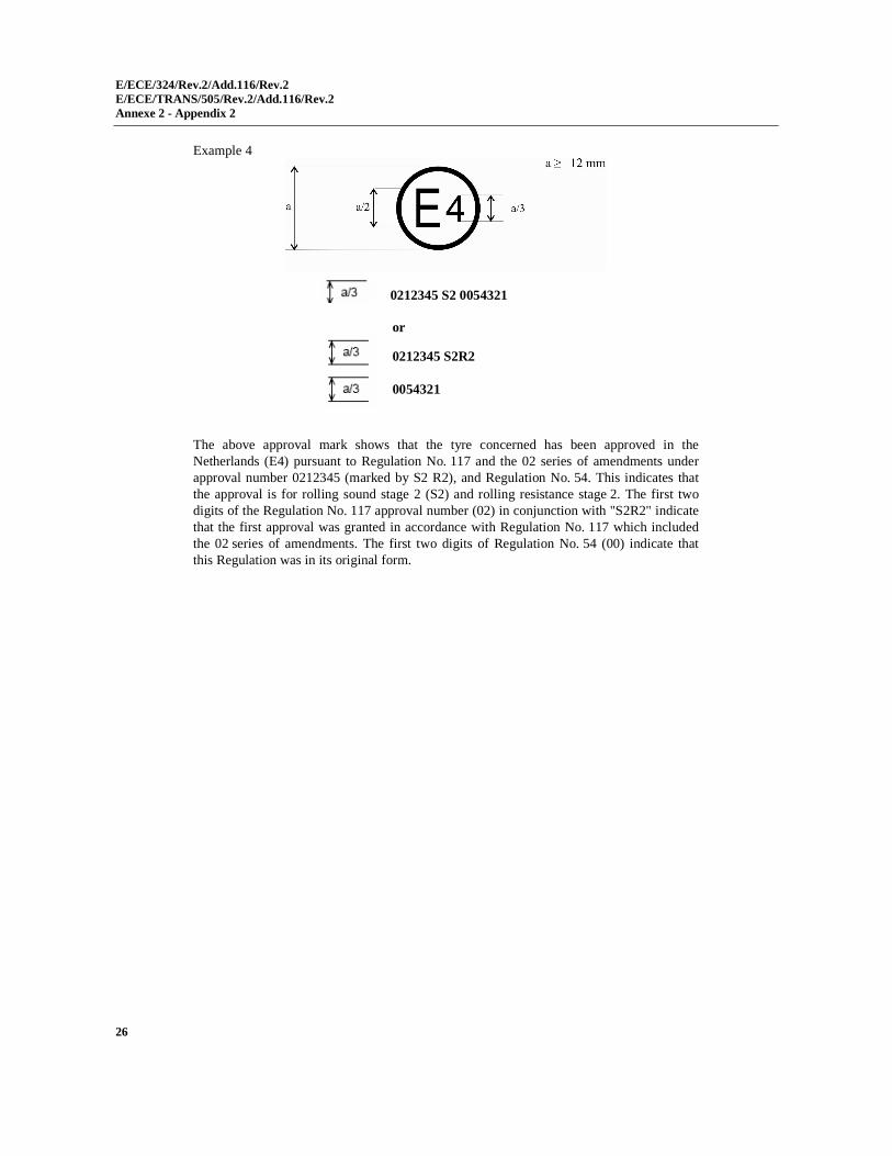
Example 4
The above approval mark shows that the tyre concerned has been approved in the Netherlands (E4) pursuant to Regulation No. 117 and the 02 series of amendments under approval number 0212345 (marked by S2 R2), and Regulation No. 54. This indicates that the approval is for rolling sound stage 2 (S2) and rolling resistance stage 2. The first two digits of the Regulation No. 117 approval number (02) in conjunction with "S2R2" indicate that the first approval was granted in accordance with Regulation No. 117 which included the 02 series of amendments. The first two digits of Regulation No. 54 (00) indicate that this Regulation was in its original form.
or
0212345 S2R2 0054321
0212345 S2 0054321
E/ECE/324/Rev.2/Add.116/Rev.2 E/ECE/TRANS/505/Rev.2/Add.116/Rev.2
Annex 2 - Appendix 3
27
Annex 2
Appendix 3
Extensions to combine approvals issued in accordance with Regulations Nos. 117, 30 or 541
Example 1
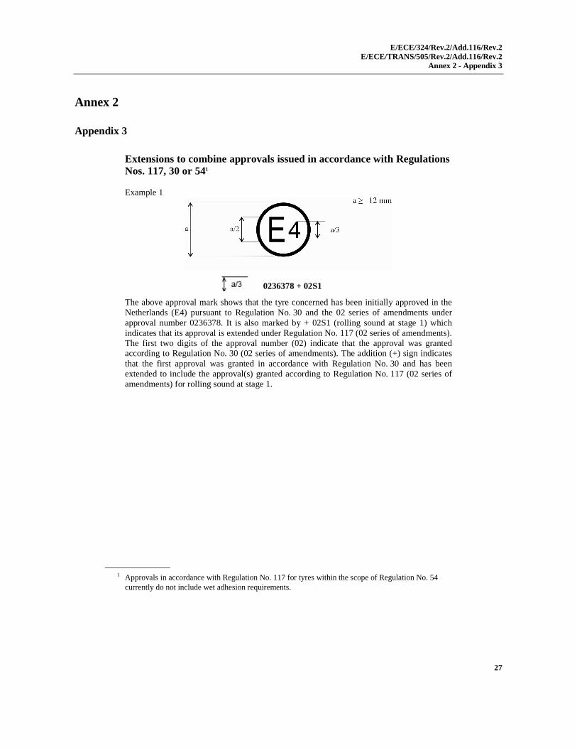
The above approval mark shows that the tyre concerned has been initially approved in the Netherlands (E4) pursuant to Regulation No. 30 and the 02 series of amendments under approval number 0236378. It is also marked by + 02S1 (rolling sound at stage 1) which indicates that its approval is extended under Regulation No. 117 (02 series of amendments). The first two digits of the approval number (02) indicate that the approval was granted according to Regulation No. 30 (02 series of amendments). The addition (+) sign indicates that the first approval was granted in accordance with Regulation No. 30 and has been extended to include the approval(s) granted according to Regulation No. 117 (02 series of amendments) for rolling sound at stage 1.
1 Approvals in accordance with Regulation No. 117 for tyres within the scope of Regulation No. 54 currently do not include wet adhesion requirements.
0236378 + 02S1
E/ECE/324/Rev.2/Add.116/Rev.2 E/ECE/TRANS/505/Rev.2/Add.116/Rev.2 Annex 2 - Appendix 3
28
Example 2
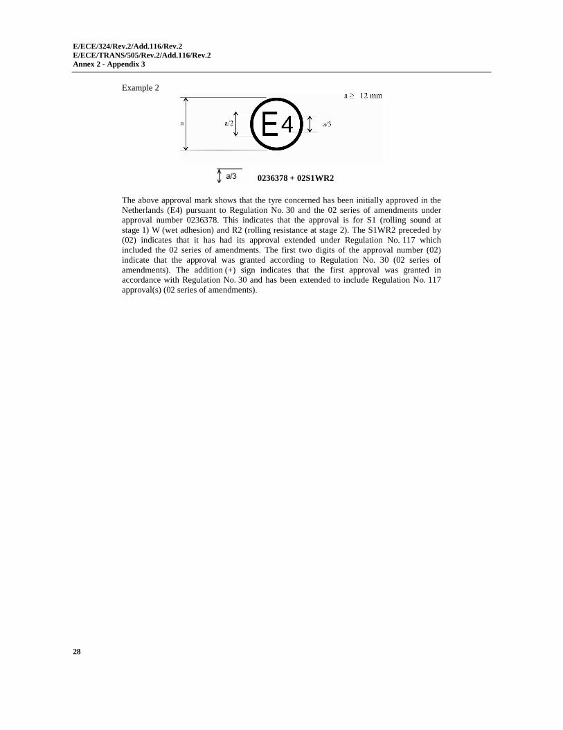
The above approval mark shows that the tyre concerned has been initially approved in the Netherlands (E4) pursuant to Regulation No. 30 and the 02 series of amendments under approval number 0236378. This indicates that the approval is for S1 (rolling sound at stage 1) W (wet adhesion) and R2 (rolling resistance at stage 2). The S1WR2 preceded by (02) indicates that it has had its approval extended under Regulation No. 117 which included the 02 series of amendments. The first two digits of the approval number (02) indicate that the approval was granted according to Regulation No. 30 (02 series of amendments). The addition (+) sign indicates that the first approval was granted in accordance with Regulation No. 30 and has been extended to include Regulation No. 117 approval(s) (02 series of amendments).
0236378 + 02S1WR2
E/ECE/324/Rev.2/Add.116/Rev.2 E/ECE/TRANS/505/Rev.2/Add.116/Rev.2
Annex 2 - Appendix 4
29
Annex 2
Appendix 4
Extensions to combine approvals issued in accordance with Regulation No. 1171
Example 1
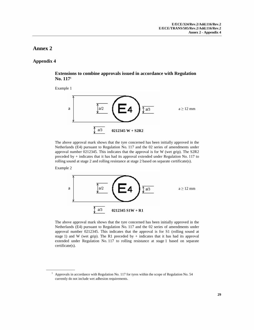
The above approval mark shows that the tyre concerned has been initially approved in the Netherlands (E4) pursuant to Regulation No. 117 and the 02 series of amendments under approval number 0212345. This indicates that the approval is for W (wet grip). The S2R2 preceded by + indicates that it has had its approval extended under Regulation No. 117 to rolling sound at stage 2 and rolling resistance at stage 2 based on separate certificate(s).
Example 2
The above approval mark shows that the tyre concerned has been initially approved in the Netherlands (E4) pursuant to Regulation No. 117 and the 02 series of amendments under approval number 0212345. This indicates that the approval is for S1 (rolling sound at stage 1) and W (wet grip). The R1 preceded by + indicates that it has had its approval extended under Regulation No. 117 to rolling resistance at stage 1 based on separate certificate(s).
1 Approvals in accordance with Regulation No. 117 for tyres within the scope of Regulation No. 54 currently do not include wet adhesion requirements.
a ≥ 12 mm
0212345 W + S2R2
a ≥ 12 mm
0212345 S1W + R1
E/ECE/324/Rev.2/Add.116/Rev.2 E/ECE/TRANS/505/Rev.2/Add.116/Rev.2 Annex 2 - Appendix 4
30
Example 3
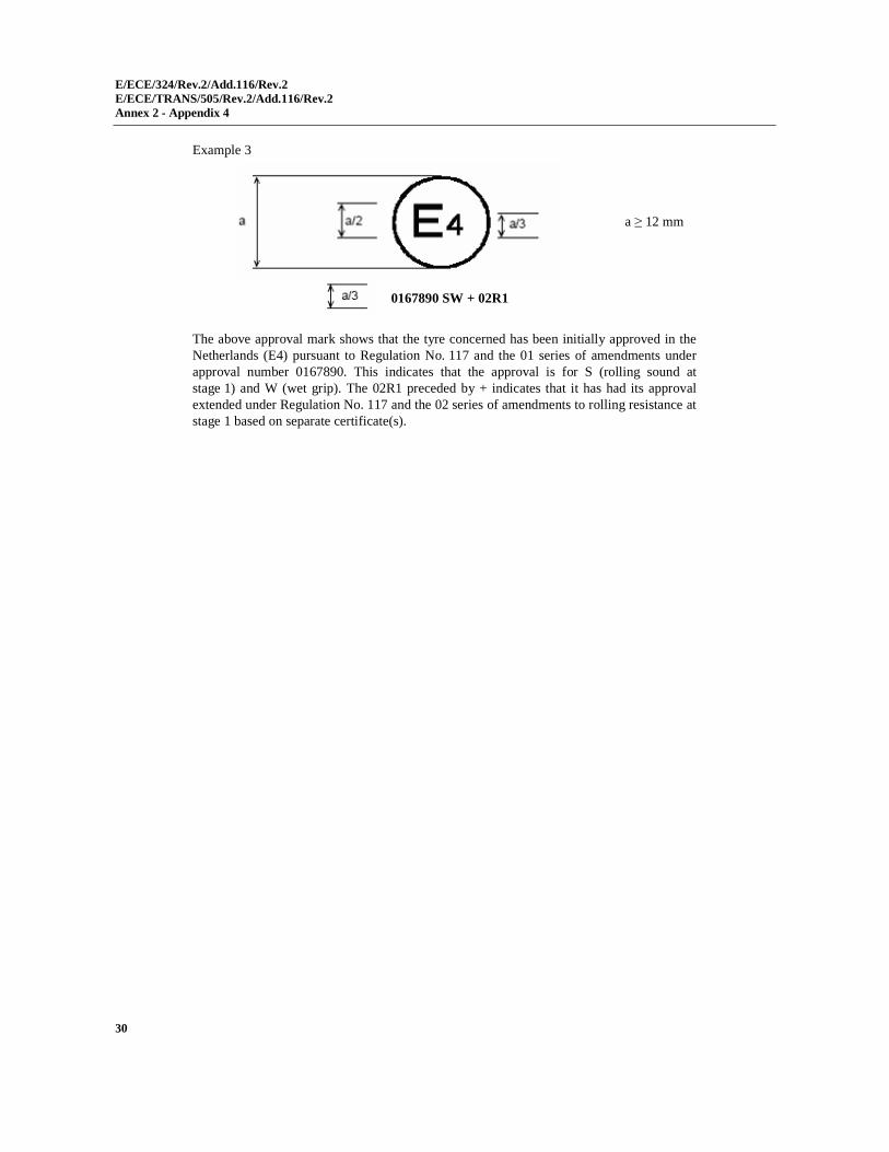
The above approval mark shows that the tyre concerned has been initially approved in the Netherlands (E4) pursuant to Regulation No. 117 and the 01 series of amendments under approval number 0167890. This indicates that the approval is for S (rolling sound at stage 1) and W (wet grip). The 02R1 preceded by + indicates that it has had its approval extended under Regulation No. 117 and the 02 series of amendments to rolling resistance at stage 1 based on separate certificate(s).
a ≥ 12 mm
0167890 SW + 02R1

E/ECE/324/Rev.2/Add.116/Rev.2 E/ECE/TRANS/505/Rev.2/Add.116/Rev.2
Annex 3
31
Annex 3
Coast-by test method for measuring tyre-rolling sound emission
0. Introduction
The presented method contains specifications on measuring instruments, measurement conditions and the measurement method, in order to obtain the sound level of a set of tyres mounted on a test vehicle rolling on a specified road surface. The maximum sound pressure level is to be recorded, when the test vehicle is coasting, by remote-field microphones; the final result for a reference speed is obtained from a linear regression analysis. Such test results cannot be related to tyre rolling sound measured during acceleration under power or deceleration under braking.
1. Measuring instruments
1.1. Acoustic measurements
The sound level meter or the equivalent measuring system, including the windscreen recommended by the manufacturer shall meet or exceed the requirements of Type 1 instruments in accordance with IEC 60651:1979/A1:1993, second edition.
The measurements shall be made using the frequency weighting A, and the time weighting F.
When using a system that includes a periodic monitoring of the A-weighted sound level, a reading should be made at a time interval not greater than 30 ms.
1.1.1. Calibration
At the beginning and at the end of every measurement session, the entire measurement system shall be checked by means of a sound calibrator that fulfils the requirements for sound calibrators of at least precision Class 1 according to IEC 60942:1988. Without any further adjustment the difference between the readings of two consecutive checks shall be less than or equal to 0.5 dB. If this value is exceeded, the results of the measurements obtained after the previous satisfactory check shall be discarded.
1.1.2. Compliance with requirements
The compliance of the sound calibration device with the requirements of IEC 60942:1988 shall be verified once a year and the compliance of the instrumentation system with the requirements of IEC 60651:1979/A1:1993, second edition shall be verified at least every two years, by a laboratory which is authorized to perform calibrations traceable to the appropriate standards.
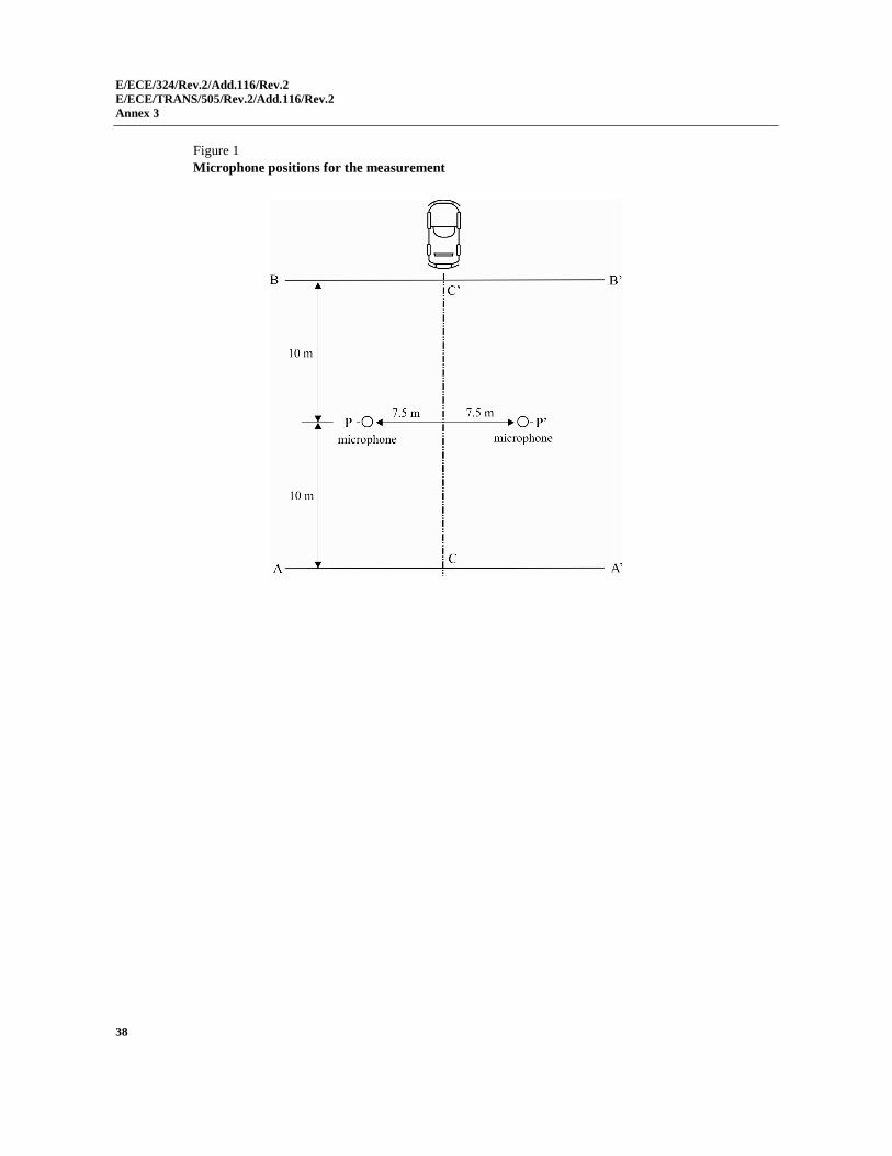
1.1.3. Positioning of the microphone
The microphone (or microphones) shall be located at a distance of 7.5 ±0.05 m from track reference line CC' (Figure 1) and 1.2 ±0.02 m above
E/ECE/324/Rev.2/Add.116/Rev.2 E/ECE/TRANS/505/Rev.2/Add.116/Rev.2 Annex 3
32
the ground. Its axis of maximum sensitivity shall be horizontal and perpendicular to the path of the vehicle (line CC').
1.2. Speed measurements
The vehicle speed shall be measured with instruments with accuracy of ±1 km/h or better when the front end of the vehicle has reached line PP (Figure 1).
1.3. Temperature measurements
Measurements of air as well as test surface temperature are mandatory.
The temperature measuring devices shall be accurate within ±1 °C.
1.3.1. Air temperature
The temperature sensor is to be positioned in an unobstructed location close to the microphone in such a way that it is exposed to the airflow and protected from direct solar radiation. The latter may be achieved by any shading screen or similar device. The sensor should be positioned at a height of 1.2 ±0.1 m above the test surface level, to minimize the influence of the test surface thermal radiation at low airflows.
1.3.2. Test surface temperature
The temperature sensor is to be positioned in a location where the temperature measured is representative of the temperature in the wheel tracks, without interfering with the sound measurement.
If an instrument with a contact temperature sensor is used, heat-conductive paste shall be applied between the surface and the sensor to ensure adequate thermal contact.
If a radiation thermometer (pyrometer) is used, the height should be chosen to ensure that a measuring spot with a diameter of ≥ 0.1 m is covered.
1.4. Wind measurement
The device shall be capable of measuring the wind speed with a tolerance of ±1 m/s. The wind shall be measured at microphone height. The wind direction with reference to the driving direction shall be recorded.
2. Conditions of measurement
2.1. Test site
The test site shall consist of a central section surrounded by a substantially flat test area. The measuring section shall be level; the test surface shall be dry and clean for all measurements. The test surface shall not be artificially cooled during or prior the testing.
The test track shall be such that the conditions of a free sound field between the sound source and the microphone are attained to within 1 dB(A). These conditions shall be deemed to be met if there are no large sound reflecting objects, such as fences, rocks, bridges or building within 50 m of the centre of the measuring section. The surface of the test track and the dimensions of the test site shall be in accordance with Annex 4 to this Regulation.
A central part of at least 10 m radius shall be free of powdery snow, tall grass, loose soil, cinders or the like. There shall be no obstacle, which could
E/ECE/324/Rev.2/Add.116/Rev.2 E/ECE/TRANS/505/Rev.2/Add.116/Rev.2
Annex 3
33
affect the sound field within the vicinity of the microphone and no persons shall stand between the microphone and the sound source. The operator carrying out the measurements and any observers attending the measurements shall position themselves so as not to affect the readings of the measuring instruments.
2.2. Meteorological conditions
Measurements shall not be made under poor atmospheric conditions. It shall be ensured that the results are not affected by gusts of wind. Testing shall not be performed if the wind speed at the microphone height exceeds 5 m/s.
Measurements shall not be made if the air temperature is below 5 °C or above 40 °C or the test surface temperature is below 5 °C or above 50 °C.
2.3. Ambient noise
2.3.1. The background sound level (including any wind noise) shall be at least 10 dB(A) less than the measured tyre rolling sound emission. A suitable windscreen may be fitted to the microphone provided that account is taken of its effect on the sensitivity and directional characteristics of the microphone.
2.3.2. Any measurement affected by a sound peak which appears to be unrelated to the characteristics of the general sound level of tyres, shall be ignored.
2.4. Test vehicle requirements
2.4.1. General
The test vehicle shall be a motor vehicle and be fitted with four single tyres on just two axles.
2.4.2. Vehicle load
The vehicle shall be loaded such as to comply with the test tyre loads as specified in paragraph 2.5.2. below.
2.4.3. Wheelbase
The wheelbase between the two axles fitted with the test tyres shall for Class C1 be less than 3.50 m and for Class C2 and Class C3 tyres be less than 5 m.
2.4.4. Measures to minimize vehicle influence on sound level measurements
To ensure that tyre rolling sound is not significantly affected by the test vehicle design the following requirements and recommendations are given.
2.4.4.1. Requirements:
(a) Spray suppression flaps or other extra device to suppress spray shall not be fitted;
(b) Addition or retention of elements in the immediate vicinity of the rims and tyres, which may screen the emitted sound, is not permitted;
(c) Wheel alignment (toe in, camber and caster) shall be in full accordance with the vehicle manufacturer's recommendations;
(d) Additional sound absorbing material may not be mounted in the wheel housings or under the underbody;
E/ECE/324/Rev.2/Add.116/Rev.2 E/ECE/TRANS/505/Rev.2/Add.116/Rev.2 Annex 3
34
(e) Suspension shall be in such a condition that it does not result in an abnormal reduction in ground clearance when the vehicle is loaded in accordance with the testing requirement. If available, body level Regulation systems shall be adjusted to give a ground clearance during testing which is normal for unladen condition.
2.4.4.2. Recommendations to avoid parasitic noise:
(a) Removal or modification on the vehicle that may contribute to the background noise of the vehicle is recommended. Any removals or modifications shall be recorded in the test report;
(b) During testing it should be ascertained that brakes are not poorly released, causing brake noise;
(c) It should be ascertained that electric cooling fans are not operating;
(d) Windows and sliding roof of the vehicle shall be closed during testing.
2.5. Tyres
2.5.1. General
Four identical tyres shall be fitted on the test vehicle. In the case of tyres with a load capacity index in excess of 121 and without any dual fitting indication, two of these tyres of the same type and range shall be fitted to the rear axle of the test vehicle; the front axle shall be fitted with tyres of size suitable for the axle load and planed down to the minimum depth in order to minimize the influence of tyre/road contact noise while maintaining a sufficient level of safety. Winter tyres that in certain Contracting Parties may be equipped with studs intended to enhance friction shall be tested without this equipment. Tyres with special fitting requirements shall be tested in accordance with these requirements (e.g. rotation direction). The tyres shall have full tread depth before being run-in.
Tyres are to be tested on rims permitted by the tyre manufacturer.
2.5.2. Tyre loads
The test load Qt for each tyre on the test vehicle shall be 50 to 90 per cent of the reference load Qr, but the average test load Qt,avr of all tyres shall be 75 ±5 per cent of the reference load Qr.
For all tyres the reference load Qr corresponds to the maximum mass associated with the load capacity index of the tyre. In the case where the load capacity index is constituted by two numbers divided by slash (/), reference shall be made to the first number.
2.5.3. Tyre inflation pressure
Each tyre fitted on the test vehicle shall have a test pressure Pt not higher than the reference pressure Pr and within the interval:
For Class C2 and Class C3 the reference pressure Pr is the pressure corresponding to the pressure index marked on the sidewall.
25 . 1 25 . 1 1 . 1
⋅ ≤ ≤
⋅
r
t r t
r
t r Q
Q P P
Q
Q P
E/ECE/324/Rev.2/Add.116/Rev.2 E/ECE/TRANS/505/Rev.2/Add.116/Rev.2
Annex 3
35
For Class C1 the reference pressure is Pr = 250 kPa for "standard" tyres and 290 kPa for "reinforced" or "extra load" tyres; the minimum test pressure shall be Pt = 150 kPa.
2.5.4. Preparations prior to testing
The tyres shall be "run-in" prior to testing to remove compound nodules or other tyre pattern characteristics resulting from the moulding process. This will normally require the equivalent of about 100 km of normal use on the road.
The tyres fitted to the test vehicle shall rotate in the same direction as when they were run-in.
Prior to testing tyres shall be warmed up by running under test conditions.
3. Method of testing
3.1. General conditions
For all measurements the vehicle shall be driven in a straight line over the measuring section (AA' to BB') in such a way that the median longitudinal plane of the vehicle is as close as possible to the line CC'.
When the front end of the test vehicle has reached the line AA' the vehicle driver shall have put the gear selector on neutral position and switched off the engine. If abnormal noise (e.g. ventilator, self-ignition) is emitted by the test vehicle during the measurement, the test shall be disregarded.
3.2. Nature and number of measurements
The maximum sound level expressed in A-weighted decibels (dB(A)) shall be measured to the first decimal place as the vehicle is coasting between lines AA' and BB' (Figure 1 - front end of the vehicle on line AA', rear end of the vehicle on line BB'). This value will constitute the result of the measurement.
At least four measurements shall be made on each side of the test vehicle at test speeds lower than the reference speed specified in paragraph 4.1. and at least four measurements at test speeds higher than the reference speed. The speeds shall be approximately equally spaced over the speed range specified in paragraph 3.3.
3.3. Test speed range
The test vehicle speeds shall be within the range:
(a) From 70 to 90 km/h for Class C1 and Class C2 tyres;
(b) From 60 to 80 km/h for Class C3 tyres.
4. Interpretation of results
The measurement shall be invalid if an abnormal discrepancy between the values is recorded (see paragraph 2.3.2. of this annex).
4.1. Determination of test result
Reference speed Vref used to determine the final result will be:
(a) 80 km/h for Class C1 and Class C2 tyres;
(b) 70 km/h for Class C3 tyres.
E/ECE/324/Rev.2/Add.116/Rev.2 E/ECE/TRANS/505/Rev.2/Add.116/Rev.2 Annex 3
36
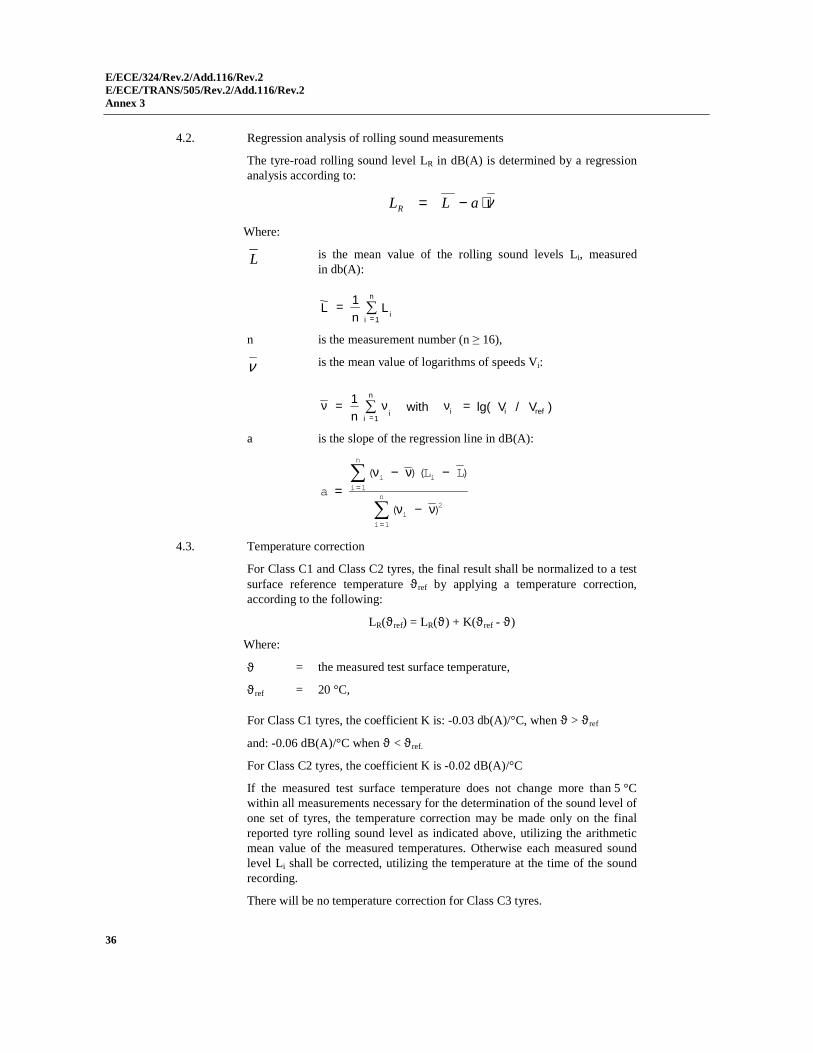
4.2. Regression analysis of rolling sound measurements
The tyre-road rolling sound level LR in dB(A) is determined by a regression analysis according to:
ν⋅−= aLLR
Where:
L is the mean value of the rolling sound levels Li, measured
in db(A):
L n
L i
i
n =
= ∑
1
1
n is the measurement number (n ≥ 16),
ν is the mean value of logarithms of speeds Vi:
ν ν ν = =
= ∑
1
1 n with V V
i i
n i ref
i lg( / )
a is the slope of the regression line in dB(A):
a
L Li ii
n
ii
n=− −
−
=
=
∑
∑
( )( )
( )
ν ν
ν ν
1
2
1
4.3. Temperature correction
For Class C1 and Class C2 tyres, the final result shall be normalized to a test surface reference temperature ϑref by applying a temperature correction, according to the following:
LR(ϑref) = LR(ϑ) + K(ϑref - ϑ)
Where:
ϑ = the measured test surface temperature,
ϑref = 20 °C,
For Class C1 tyres, the coefficient K is: -0.03 db(A)/°C, when ϑ > ϑref
and: -0.06 dB(A)/°C when ϑ < ϑref.
For Class C2 tyres, the coefficient K is -0.02 dB(A)/°C
If the measured test surface temperature does not change more than 5 °C within all measurements necessary for the determination of the sound level of one set of tyres, the temperature correction may be made only on the final reported tyre rolling sound level as indicated above, utilizing the arithmetic mean value of the measured temperatures. Otherwise each measured sound level Li shall be corrected, utilizing the temperature at the time of the sound recording.
There will be no temperature correction for Class C3 tyres.

E/ECE/324/Rev.2/Add.116/Rev.2 E/ECE/TRANS/505/Rev.2/Add.116/Rev.2
Annex 3
37
4.4. In order to take account of any measuring instrument inaccuracies, the results according to paragraph 4.3. shall be reduced by 1 dB(A).
4.5. The final result, the temperature corrected tyre rolling sound level LR(ϑref) in dB(A), shall be rounded down to the nearest lower whole value.
E/ECE/324/Rev.2/Add.116/Rev.2 E/ECE/TRANS/505/Rev.2/Add.116/Rev.2 Annex 3
38
Figure 1 Microphone positions for the measurement
E/ECE/324/Rev.2/Add.116/Rev.2 E/ECE/TRANS/505/Rev.2/Add.116/Rev.2
Annex 3 - Appendix 1
39
Annex 3
Appendix 1
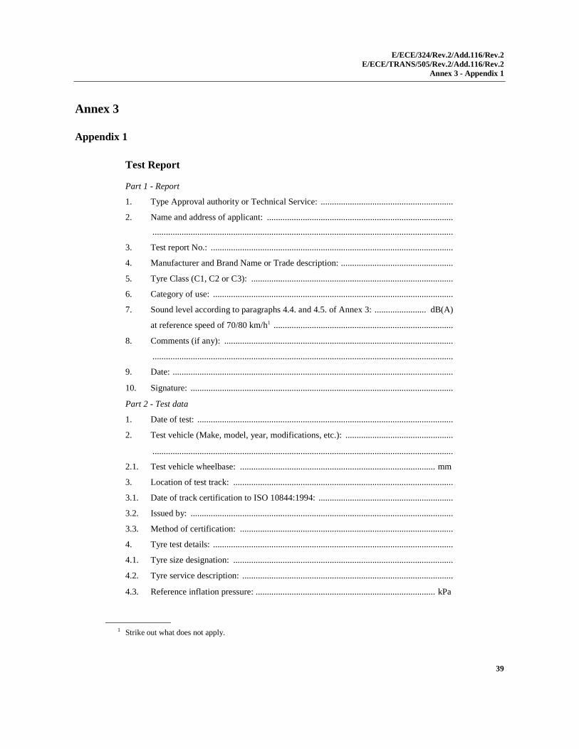
Test Report
Part 1 - Report
1. Type Approval authority or Technical Service: ...........................................................
2. Name and address of applicant: ...................................................................................
......................................................................................................................................
3. Test report No.: ............................................................................................................
4. Manufacturer and Brand Name or Trade description: ..................................................
5. Tyre Class (C1, C2 or C3): ..........................................................................................
6. Category of use: ...........................................................................................................
7. Sound level according to paragraphs 4.4. and 4.5. of Annex 3: ....................... dB(A)
at reference speed of 70/80 km/h1 ................................................................................
8. Comments (if any): ......................................................................................................
......................................................................................................................................
9. Date: .............................................................................................................................
10. Signature: .....................................................................................................................
Part 2 - Test data
1. Date of test: ..................................................................................................................
2. Test vehicle (Make, model, year, modifications, etc.): ................................................
......................................................................................................................................
2.1. Test vehicle wheelbase: ....................................................................................... mm
3. Location of test track: ..................................................................................................
3.1. Date of track certification to ISO 10844:1994: ............................................................
3.2. Issued by: .....................................................................................................................
3.3. Method of certification: ...............................................................................................
4. Tyre test details: ...........................................................................................................
4.1. Tyre size designation: ..................................................................................................
4.2. Tyre service description: ..............................................................................................
4.3. Reference inflation pressure: ................................................................................ kPa
1 Strike out what does not apply.
E/ECE/324/Rev.2/Add.116/Rev.2 E/ECE/TRANS/505/Rev.2/Add.116/Rev.2 Annex 3 - Appendix 1
40
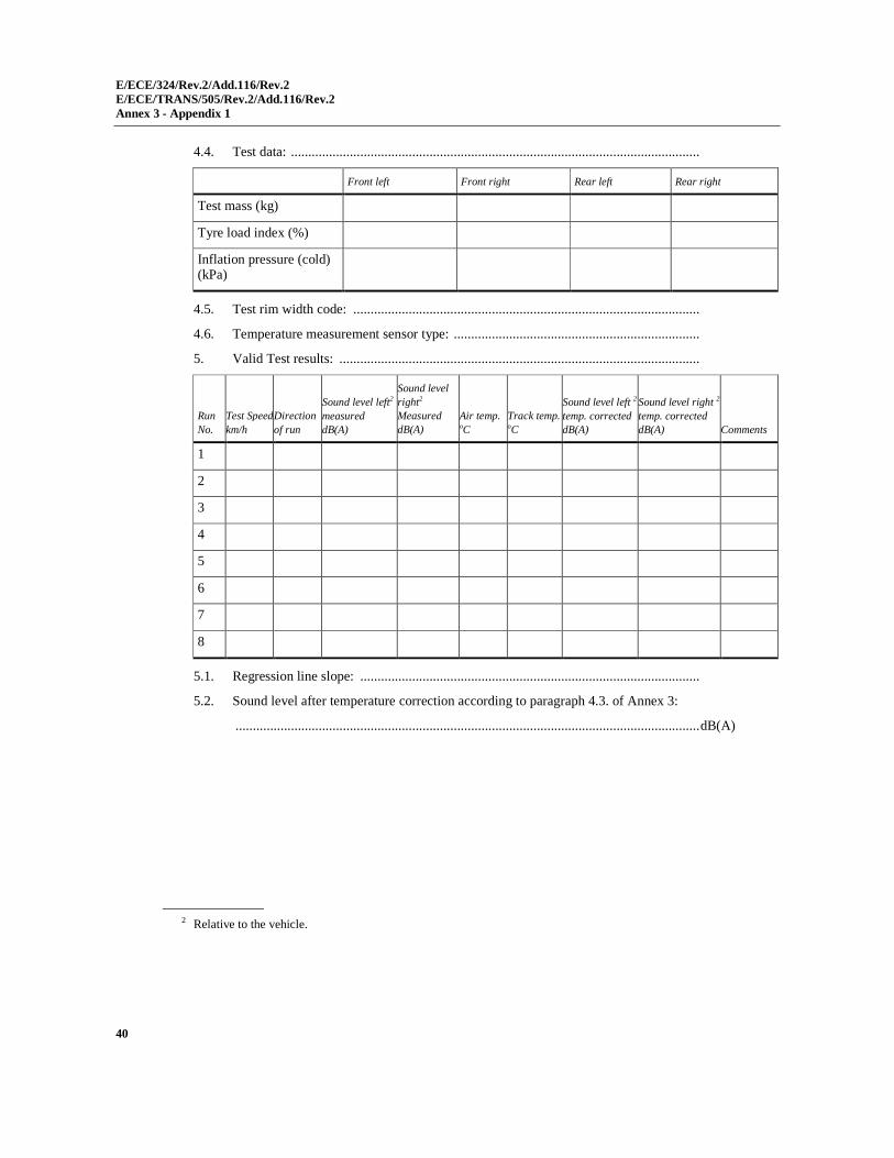
4.4. Test data: ......................................................................................................................
Front left Front right Rear left Rear right
Test mass (kg)
Tyre load index (%)
Inflation pressure (cold) (kPa)
4.5. Test rim width code: ....................................................................................................
4.6. Temperature measurement sensor type: .......................................................................
5. Valid Test results: ........................................................................................................
Run No.
Test Speedkm/h
Direction of run
Sound level left2 measured dB(A)
Sound level right2 Measured dB(A)
Air temp. oC
Track temp. oC
Sound level left 2 temp. corrected dB(A)
Sound level right 2
temp. corrected dB(A) Comments
1
2
3
4
5
6
7
8
5.1. Regression line slope: ..................................................................................................
5.2. Sound level after temperature correction according to paragraph 4.3. of Annex 3:
......................................................................................................................................dB(A)
2 Relative to the vehicle.
E/ECE/324/Rev.2/Add.116/Rev.2 E/ECE/TRANS/505/Rev.2/Add.116/Rev.2
Annex 4
41
Annex 4
Specifications for the test site
1. Introduction
This annex describes the specifications relating to the physical characteristics and the laying of the test track. These specifications based on a special standard1 describe the required physical characteristics as well as the test methods for these characteristics.
2. Required characteristics of the surface
A surface is considered to conform to this standard provided that the texture and voids content or sound absorption coefficient have been measured and found to fulfil all the requirements of paragraphs 2.1. to 2.4. below and provided that the design requirements (paragraph 3.2.) have been met.
2.1. Residual voids content
The residual voids content (VC) of the test track paving mixture shall not exceed 8 per cent. For the measurement procedure, see paragraph 4.1.
2.2. Sound absorption coefficient
If the surface fails to comply with the residual voids content requirement, the surface is acceptable only if its sound absorption coefficient α ≤ 0.10. For the measurement procedure, see paragraph 4.2. The requirement of paragraphs 2.1. and 2.2. is met also if only sound absorption has been measured and found to be α ≤ 0.10.
Note: The most relevant characteristic is the sound absorption, although the residual voids content is more familiar among road constructors. However, sound absorption needs to be measured only if the surface fails to comply with the voids requirement. This is motivated because the latter is connected with relatively large uncertainties in terms of both measurements and relevance and some surfaces therefore erroneously may be rejected when based only on the voids measurement.
2.3. Texture depth
The texture depth (TD) measured according to the volumetric method (see paragraph 4.3. below) shall be:
TD ≥ 0.4 mm
2.4. Homogeneity of the surface
Every practical effort shall be taken to ensure that the surface is made to be as homogeneous as possible within the test area. This includes the texture and voids content, but it should also be observed that if the rolling process results
1 ISO 10844:1994.
E/ECE/324/Rev.2/Add.116/Rev.2 E/ECE/TRANS/505/Rev.2/Add.116/Rev.2 Annex 4
42
in more effective rolling at some places than others, the texture may be different and unevenness causing bumps may also occur.
2.5. Period of testing
In order to check whether the surface continues to conform to the texture and voids content or sound absorption requirements stipulated in this standard, periodic testing of the surface shall be done at the following intervals:
(a) For residual voids content (VC) or sound absorption (α):
When the surface is new:
If the surface meets the requirements when new, no further periodical testing is required. If it does not meet the requirement when it is new, it may do so later because surfaces tend to become clogged and compacted with time;
(b) For texture depth (TD):
When the surface is new:
When the noise testing starts (Note: not before four weeks after laying);
Then every twelve months.
3. Test surface design
3.1. Area
When designing the test track layout it is important to ensure that, as a minimum requirement, the area traversed by the vehicles running through the test strip is covered with the specified test material with suitable margins for safe and practical driving. This will require that the width of the track is at least 3 m and the length of the track extends beyond lines AA and BB by at least 10 m at either end. Figure 1 shows a plan of a suitable test site and indicates the minimum area which shall be machine laid and machine compacted with the specified test surface material. According to Annex 3, paragraph 3.2., measurements have to be made on each side of the vehicle. This can be made either by measuring with two microphone locations (one on each side of the track) and driving in one direction, or measuring with a microphone only on one side of the track but driving the vehicle in two directions. If the latter method is used, then there are no surface requirements on that side of the track where there is no microphone.
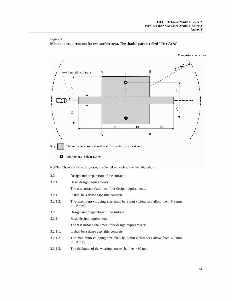
E/ECE/324/Rev.2/Add.116/Rev.2 E/ECE/TRANS/505/Rev.2/Add.116/Rev.2
Annex 4
43
Figure 1 Minimum requirements for test surface area. The shaded part is called "Test Area"
3.2. Design and preparation of the surface
3.2.1. Basic design requirements
The test surface shall meet four design requirements:
3.2.1.1. It shall be a dense asphaltic concrete.
3.2.1.2. The maximum chipping size shall be 8 mm (tolerances allow from 6.3 mm to 10 mm).
3.2. Design and preparation of the surface
3.2.1. Basic design requirements
The test surface shall meet four design requirements:
3.2.1.1. It shall be a dense asphaltic concrete.
3.2.1.2. The maximum chipping size shall be 8 mm (tolerances allow from 6.3 mm to 10 mm).
3.2.1.3. The thickness of the wearing course shall be ≥ 30 mm.
E/ECE/324/Rev.2/Add.116/Rev.2 E/ECE/TRANS/505/Rev.2/Add.116/Rev.2 Annex 4
44
3.2.1.4. The binder shall be a straight penetration grade bitumen without modification.
3.2.2. Design guidelines
As a guide to the surface constructor, an aggregate grading curve which will give desired characteristics is shown in Figure 2. In addition, Table 1 gives some guidelines in order to obtain the desired texture and durability. The grading curve fits the following formula:
P (% passing) = 100 · (d/dmax) 1/2
Where:
d = square mesh sieve size, in mm
dmax = 8 mm for the mean curve
= 10 mm for the lower tolerance curve
= 6.3 mm for the upper tolerance curve
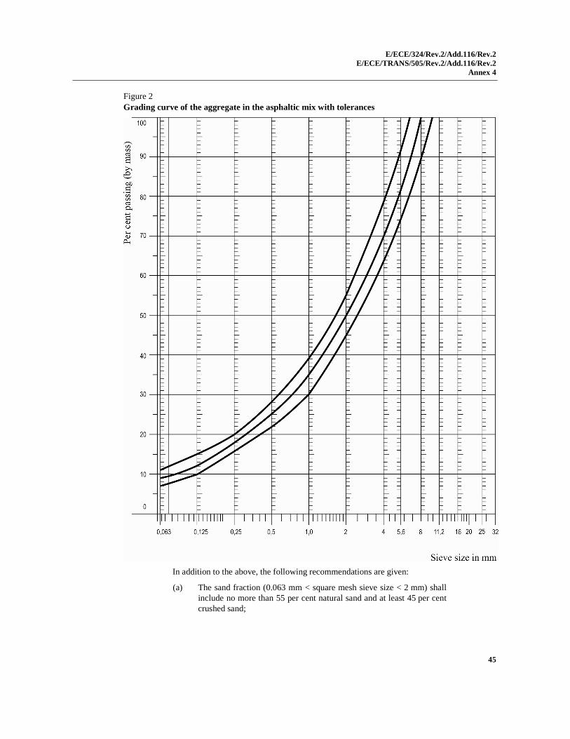
E/ECE/324/Rev.2/Add.116/Rev.2 E/ECE/TRANS/505/Rev.2/Add.116/Rev.2
Annex 4
45
Figure 2 Grading curve of the aggregate in the asphaltic mix with tolerances
In addition to the above, the following recommendations are given:
(a) The sand fraction (0.063 mm < square mesh sieve size < 2 mm) shall include no more than 55 per cent natural sand and at least 45 per cent crushed sand;
E/ECE/324/Rev.2/Add.116/Rev.2 E/ECE/TRANS/505/Rev.2/Add.116/Rev.2 Annex 4
46
(b) The base and sub-base shall ensure a good stability and evenness, according to best road construction practice;
(c) The chippings shall be crushed (100 per cent crushed faces) and of a material with a high resistance to crushing;
(d) The chippings used in the mix shall be washed;
(e) No extra chippings shall be added onto the surface;
(f) The binder hardness expressed as PEN value shall be 40 - 60, 60 - 80 or even 80 - 100 depending on the climatic conditions of the country. The rule is that as hard a binder as possible shall be used, provided this is consistent with common practice;
(g) The temperature of the mix before rolling shall be chosen so as to achieve by subsequent rolling the required voids content. In order to increase the probability of satisfying the specifications of paragraphs 2.1. to 2.4. above, the compactness shall be studied not only by an appropriate choice of mixing temperature, but also by an appropriate number of passings and by the choice of compacting vehicle.
Table 1 Design guidelines
Target values
By total mass of mix
By mass of the aggregate
Tolerances
Mass of stones, square mesh sieve (SM) > 2 mm
47.6 %
50.5 %
±5 %
Mass of sand 0.063 < SM < 2 mm 38.0 % 40.2 % ±5 %
Mass of filler SM < 0.063 mm 8.8 % 9.3 % ±5 %
Mass of binder (bitumen) 5.8 % N.A. ±0.5 %
Max. chipping size 8 mm 6.3 - 10 mm
Binder hardness (see paragraph 3.2.2. (f))
Polished stone value (PSV) > 50
Compactness, relative to Marshall Compactness
98 %
4. Test method
4.1. Measurement of the residual voids content
For the purpose of this measurement, cores have to be taken from the track in at least four different positions, which are equally distributed in the test area between lines AA and BB (see Figure 1). In order to avoid in homogeneity and unevenness in the wheel tracks, cores should not be taken in wheel tracks themselves, but close to them. Two cores (minimum) should be taken close to
E/ECE/324/Rev.2/Add.116/Rev.2 E/ECE/TRANS/505/Rev.2/Add.116/Rev.2
Annex 4
47
the wheel tracks and one core (minimum) should be taken approximately midway between the wheel tracks and each microphone location.
If there is a suspicion that the condition of homogeneity is not met (see paragraph 2.4.), cores shall be taken from more locations within the test area.
The residual voids content has to be determined for each core, then the average value from all cores shall be calculated and compared with the requirement of paragraph 2.1. In addition, no single core shall have a voids value, which is higher than 10 per cent.
The test surface constructor is reminded of the problem, which may arise when the test area is heated by pipes or electrical wires and cores shall be taken from this area. Such installations shall be carefully planned with respect to future core drilling locations. It is recommended to leave a few locations of size approximately 200 mm x 300 mm where there are no wires/pipes or where the latter are located deep enough in order not to be damaged by cores taken from the surface layer.
4.2. Sound absorption coefficient
The sound absorption coefficient (normal incidence) shall be measured by the impedance tube method using the procedure specified in ISO 10534-1:1996 or ISO 10534-2:1998.
Regarding test specimens, the same requirements shall be followed as regarding the residual voids content (see paragraph 4.1.). The sound absorption shall be measured in the range between 400 Hz and 800 Hz and in the range between 800 Hz and 1,600 Hz (at least at the centre frequencies of third octave bands) and the maximum values shall be identified for both of these frequency ranges. Then these values, for all test cores, shall be averaged to constitute the final result.
4.3. Volumetric macro-texture measurement
For the purpose of this standard, texture depth measurements shall be made on at least 10 positions evenly spaced along the wheel tracks of the test strip and the average value taken to compare with the specified minimum texture depth. See Standard ISO 10844:1994 for description of the procedure.
5. Stability in time and maintenance
5.1. Age influence
In common with any other surfaces, it is expected that the tyre rolling sound level measured on the test surface may increase slightly during the first 6-12 months after construction.
The surface will achieve its required characteristics not earlier than four weeks after construction. The influence of age on the noise from trucks is generally less than that from cars.
The stability over time is determined mainly by the polishing and compaction by vehicles driving on the surface. It shall be periodically checked as stated in paragraph 2.5.
E/ECE/324/Rev.2/Add.116/Rev.2 E/ECE/TRANS/505/Rev.2/Add.116/Rev.2 Annex 4
48
5.2. Maintenance of the surface
Loose debris or dust, which could significantly reduce the effective texture depth shall be removed from the surface. In countries with winter climates, salt is sometimes used for de-icing. Salt may alter the surface temporarily or even permanently in such a way as to increase noise and is therefore not recommended.
5.3. Repaving the test area
If it is necessary to repave the test track, it is usually unnecessary to repave more than the test strip (of 3 m width in Figure 1) where vehicles are driving, provided the test area outside the strip met the requirement of residual voids content or sound absorption when it was measured.
6. Documentation of the test surface and of tests performed on it
6.1. Documentation of the test surface
The following data shall be given in a document describing the test surface:
6.1.1. The location of the test track;
6.1.2. Type of binder, binder hardness, type of aggregate, maximum theoretical density of the concrete (DR), thickness of the wearing course and grading curve determined from cores from the test track;
6.1.3. Method of compaction (e.g. type of roller, roller mass, number of passes);
6.1.4. Temperature of the mix, temperature of the ambient air and wind speed during laying of the surface;
6.1.5. Date when the surface was laid and contractor;
6.1.6. All or at least the latest test result, including:
6.1.6.1. The residual voids content of each core;
6.1.6.2. The locations in the test area from where the cores for voids measurements have been taken;
6.1.6.3. The sound absorption coefficient of each core (if measured). Specify the results both for each core and each frequency range as well as the overall average;
6.1.6.4. The locations in the test area from where the cores for absorption measurement have been taken;
6.1.6.5. Texture depth, including the number of tests and standard deviation;
6.1.6.6. The institution responsible for tests according to paragraphs 6.1.6.1. and 6.1.6.2. and the type of equipment used;
6.1.6.7. Date of the test(s) and date when the cores were taken from the test track.
6.2. Documentation of vehicle noise tests conducted on the surface
In the document describing the vehicle noise test(s) it shall be stated whether all the requirements of this standard were fulfilled or not. Reference shall be given to a document according to paragraph 6.1. describing the results which verify this.
E/ECE/324/Rev.2/Add.116/Rev.2 E/ECE/TRANS/505/Rev.2/Add.116/Rev.2
Annex 5
49
Annex 5
Test procedure for measuring wet grip
1. General Test Conditions
1.1. Track characteristics
The track shall have a dense asphalt surface with a gradient in any direction not exceeding 2 per cent. It shall be of uniform age, composition, and wear and shall be free of loose material or foreign deposits. The maximum chipping size shall be 10 mm (tolerances permitted from 8 mm to 13 mm) and the sand depth measured as specified in ASTM standard E 965-96 (2006) shall be 0.7 ±0.3 mm.
The surface friction value for the wetted track shall be established by one or other of the following methods:
1.1.1. Standard reference test tyre (SRTT) method
When tested using the SRTT and the method given in paragraph 2.1. the average peak brake force coefficient (pbfc) shall be between 0.6 and 0.8. The measured values shall be corrected for the effects of temperature as follows:
pbfc = pbfc (measured) + 0.0035 (t - 20)
where "t" is the wetted track surface temperature in degrees Celsius.
The test shall be conducted using the lanes and length of the track to be used for the wet grip test;
1.1.2. British pendulum number (BPN) method
The averaged British pendulum number (BPN) of the wetted track, measured in accordance with the procedure given in the ASTM standard E 303-93 (2008) and using the pad as specified in ASTM standard E 501-08, shall be between 40 and 60 after temperature correction. Unless temperature correction recommendations are indicated by the pendulum manufacturer, the following formula can be used:
BPN = BPN (measured value) + 0.34 · t − 0.0018 · t² − 6.1
where "t" is the wetted track surface temperature in degrees Celsius.
In the lanes of the track to be used during the wet grip tests, the BPN shall be measured at intervals of 10 m along the length of the lanes. The BPN shall be measured 5 times at each point and the coefficient of variation of the BPN averages shall not exceed by 10 per cent.
1.1.3. The Type Approval Authority shall satisfy itself of the characteristics of the track on the basis of evidence produced in test reports.
1.2. Wetting conditions
The surface may be wetted from the track-side or by a wetting system incorporated into the test vehicle or the trailer.
E/ECE/324/Rev.2/Add.116/Rev.2 E/ECE/TRANS/505/Rev.2/Add.116/Rev.2 Annex 5
50
If a track-side system is used, the test surface shall be wetted for at least half an hour prior to testing in order to equalize the surface temperature and water temperature. It is recommended that track-side wetting be continuously applied throughout testing.
The water depth shall be between 0.5 and 1.5 mm.
1.3. The wind conditions shall not interfere with wetting of the surface (wind-shields are permitted).
The wetted surface temperature shall be between 5 °C and 35 °C and shall not vary during the test by more than 10 °C.
2. Test Procedure
The comparative wet grip performance shall be established using either:
(a) A trailer or special purpose tyre evaluation vehicle; or
(b) A standard production passenger carrying vehicle (M1 category as defined in the Consolidated Resolution on the Construction of Vehicles (R.E.3.) contained in ECE/TRANS/WP.29/78/Rev.2.
2.1. Trailer or special purpose tyre evaluation vehicle procedure
2.1.1. The trailer, together with the towing vehicle, or the tyre evaluation vehicle shall comply with the following requirements:
2.1.1.1. Be capable of exceeding the upper limit for the test speed of 67 km/h and of maintaining the test speed requirement of 65 ±2 km/h at the maximum level of application of braking forces;
2.1.1.2. Be equipped with an axle providing one test position having an hydraulic brake and actuation system that can be operated from the towing vehicle if applicable. The braking system shall be capable of providing sufficient braking torque to achieve the peak brake force coefficient over the range of tyre sizes and tyre loads to be tested;
2.1.1.3. Be capable of maintaining longitudinal alignment (toe) and camber of the test wheel and tyre assembly throughout the test within ±0.5° of the static figures achieved at the test tyre loaded condition;
2.1.1.4. In the case of a trailer, the mechanical coupling device between the towing vehicle and trailer shall be such that, when the towing vehicle and trailer are coupled together, the drawbar, or part of the drawbar, of a trailer that incorporates the braking force measurement sensing is horizontal or slopes downwards from rear to front at a maximum angle of 5º. The longitudinal distance from the centre line of the articulation point of the coupling (hitch) to the transverse centre line of the axle of the trailer shall be at least ten times the coupling (hitch) height;
2.1.1.5. In the case of vehicles that incorporate a track wetting system, the water delivery nozzle(s) shall be such that the resulting water film is of uniform section extending at least 25 mm beyond the width of the tyre contact patch. The nozzle(s) shall be directed downwards at an angle of 20° to 30° and shall contact the track surface between 250 mm and 450 mm in front of the centre of the tyre contact patch. The height of the nozzle(s) shall be 25 mm or the minimum to avoid any obstacles on the track surface without exceeding a
E/ECE/324/Rev.2/Add.116/Rev.2 E/ECE/TRANS/505/Rev.2/Add.116/Rev.2
Annex 5
51
maximum of 100 mm. Water delivery rate shall ensure a water depth of 0.5 mm to 1.5 mm and shall be consistent throughout the test to within ±10 per cent. Note that a typical rate for testing at 65 km/h will be 18 ls−1 per metre of wetted track surface width.
The system shall be able to deliver the water such that the tyre, and track surface in front of the tyre, is wetted before the start of braking and throughout the duration of the test.
2.1.2. Test procedure
2.1.2.1. The test tyre shall be trimmed to remove any moulding protrusions that are likely to affect the test.
2.1.2.2. The test tyre shall be mounted on the test rim declared by the tyre manufacturer in the approval application and shall be inflated to 180 kPa in the case of the SRTT and standard load tyre or 220 kPa in the case of a reinforced or extra load tyre.
2.1.2.3. The tyre shall be conditioned for a minimum of two hours adjacent to the test track such that it is stabilized at the ambient temperature of the test track area. The tyre(s) shall not be exposed to direct sunshine during conditioning.
2.1.2.4. The tyre shall be loaded to:
(a) Between 445 kg and 508 kg in the case of the SRTT; and
(b) Between 70 per cent and 80 per cent of the load value corresponding to the load index of the tyre in any other case.
2.1.2.5. Shortly before testing, the track shall be conditioned by carrying out at least ten braking tests on the part of the track to be used for the performance test programme but using a tyre not involved in that programme.
2.1.2.6. Immediately prior to testing, the tyre inflation pressure shall be checked and reset, if necessary, to the values given in paragraph 2.1.2.2.
2.1.2.7. The test speed shall be between 63 km/h and 67 km/h and shall be maintained between these limits throughout the test run.
2.1.2.8. The direction of the test shall be the same for each set of tests and shall be the same for the test tyre as that used for the SRTT with which its performance is to be compared.
2.1.2.9. The brakes of the test wheel assembly shall be applied such that peak braking force is achieved within 0.2 s and 0.5 s of brake application.
2.1.2.10. In the case of a new tyre, two test runs shall be carried out to condition the tyre. These tests may be used to check the operation of the recording equipment but the results shall not be taken into account in the performance assessment.
2.1.2.11. For the evaluation of the performance of any tyre compared with that of the SRTT, the braking test shall be carried out from the same point and in the same lane of the test track.
2.1.2.12. The order of testing shall be:
R1 - T - R2
E/ECE/324/Rev.2/Add.116/Rev.2 E/ECE/TRANS/505/Rev.2/Add.116/Rev.2 Annex 5
52
Where:
R1 is the initial test of the SRTT, R2 is the repeat test of the SRTT and T is the test of the candidate tyre to be evaluated.
A maximum of three candidate tyres may be tested before repeating the SRTT test, for example:
R1 - T1 - T2 - T3 - R2
2.1.2.13. The average value of peak brake force coefficient (pbfc) shall be calculated over at least six valid results.
For results to be considered to be valid, the coefficient of variation as determined by the standard deviation divided by the average result, expressed as a percentage, shall be within 5 per cent. If this is cannot achieved with the repeat testing of the SRTT, the evaluation of the candidate tyre(s) shall be discarded and the entire order of testing shall be repeated.
2.1.2.14. Using the value of the average pbfc for each series of test runs:
In the case of the order of testing R1 - T - R2, the pbfc of the SRTT to be used in the comparison of the performance of the candidate tyre shall be taken to be:
(R1 + R2)/2
Where:
R1 is the average pbfc for the first series of test runs of the SRTT and R2 is the average pbfc for the second series of test runs of the SRTT
In the case of the order of testing R1 - T1 - T2 - R2, the pbfc of the SRTT shall be taken to be:
2/3 R1 + 1/3 R2 for comparison with the candidate tyre T1 and
1/3 R1 + 2/3 R2 for comparison with the candidate tyre T2
In the case of the order of testing R1 - T1 - T2 - T3 - R2, the pbfc of the SRTT shall be taken to be:
3/4 R1 + 1/4 R2 for comparison with the candidate tyre T1
(R1 + R2)/2 for comparison with the candidate tyre T2 and
1/4 R1 + 3/4 R2 for comparison with the candidate tyre T3
2.1.2.15. The wet grip index (G) shall be calculated as:
pbfc of candidate tyre G =
pbfc of SRTT
2.2. Standard vehicle procedure
2.2.1. The vehicle shall be a standard M1 category vehicle, capable of a minimum speed of 90 km/h and equipped with an anti-lock braking system (ABS).
2.2.1.1. The vehicle shall not be modified except:
(a) To allow the fitting of an increased range of wheel and tyre sizes;
E/ECE/324/Rev.2/Add.116/Rev.2 E/ECE/TRANS/505/Rev.2/Add.116/Rev.2
Annex 5
53
(b) To allow mechanical (including hydraulic, electrical or pneumatic) operation of the service brake control. The system may be operated automatically by signals from devices incorporated in, or adjacent to, the track.
2.2.2. Test procedure
2.2.2.1. The test tyres shall be trimmed to remove any moulding protrusions that are likely to affect the test.
2.2.2.2. The test tyre shall be mounted on the test rim declared by the tyre manufacturer in the approval application and shall be inflated to 220 kPa in all cases.
2.2.2.3. The tyre shall be conditioned for a minimum of two hours adjacent to the test track such that it is stabilized at the ambient temperature of the test track area. The tyre(s) shall not be exposed to direct sunshine during conditioning.
2.2.2.4. The static load on the tyre shall be:
(a) Between 381 kg and 572 kg in the case of the SRTT; and
(b) Between 60 per cent and 90 per cent of the load value corresponding to the load index of the tyre in any other case.
The variation in load on tyres on the same axle shall be such that the load borne by the more lightly loaded tyre shall not be less than 90 per cent of that of the tyre bearing the greater load.
2.2.2.5. Shortly before testing, the track shall be conditioned by carrying out at least ten braking tests from 90 km/h to 20 km/h on the part of the track to be used for the performance test programme but using tyres not involved in that programme.
2.2.2.6. Immediately prior to testing, the tyre inflation pressure shall be checked and reset, if necessary, to the values given in paragraph 2.2.2.2.
2.2.2.7. Starting from an initial speed of between 87 km/h and 83 km/h, a constant force sufficient to cause operation of the ABS on all wheels of the vehicle and to result in stable deceleration of the vehicle prior to the speed being reduced to 80 km/h, shall be applied to the service brake control and this force shall be maintained until the vehicle has been brought to rest.
The braking test shall be carried out with the clutch of a manual transmission disengaged or with the selector of an automatic transmission in the neutral position.
2.2.2.8. The direction of the test shall be the same for each set of tests and shall be the same for the candidate test tyre as that used for the SRTT with which its performance is to be compared.
2.2.2.9. In the case of new tyres, two test runs shall be carried out to condition the tyres. These tests may be used to check the operation of the recording equipment but the results shall not be taken into account in the performance assessment.
2.2.2.10. For the evaluation of the performance of any tyre compared with that of the SRTT, the braking test shall be carried out from the same point and in the same lane of the test track.
E/ECE/324/Rev.2/Add.116/Rev.2 E/ECE/TRANS/505/Rev.2/Add.116/Rev.2 Annex 5
54
2.2.2.11. The order of testing shall be:
R1 - T - R2
Where:
R1 is the initial test of the SRTT, R2 is the repeat test of the SRTT and T is the test of the candidate tyre to be evaluated.
A maximum of three candidate tyres may be tested before repeating the SRTT test, for example:
R1-T1 - T2 - T3 - R2
2.2.2.12. The mean fully developed deceleration (mfdd) between 80 km/h and 20 km/h shall be calculated for at least three valid results in the case of the SRTT and 6 valid results in the case of the candidate tyres.
The mean fully developed deceleration (mfdd) is given by:
mfdd = 231.48 / S
Where:
S is the measured stopping distance in metres between 80 km/h and 20 km/h.
For results to be considered to be valid, the coefficient of variation as determined by the standard deviation divided by the average result, expressed as a percentage, shall be within 3 per cent. If this is cannot achieved with the repeat testing of the SRTT, the evaluation of the candidate tyre(s) shall be discarded and the entire order of testing shall be repeated.
The average of the calculated values of mfdd shall be determined for each series of test runs.
2.2.2.13. Using the value of the average mfdd for each series of test runs:
In the case of the order of testing R1 - T - R2, the mfdd of the SRTT to be used in the comparison of the performance of the candidate tyre shall be taken to be:
(R1 + R2)/2
Where:
R1 is the average mfdd for the first series of test runs of the SRTT and R2 is the average mfdd for the second series of test runs of the SRTT
In the case of the order of testing R1 - T1 - T2 - R2, the mfdd of the SRTT shall be taken to be:
2/3 R1 + 1/3 R2 for comparison with the candidate tyre T1 and
1/3 R1 + 2/3 R2 for comparison with the candidate tyre T2
In the case of the order of testing R1 - T1 - T2 - T3 - R2, the mfdd of the SRTT shall be taken to be:
3/4 R1 + 1/4 R2 for comparison with the candidate tyre T1
(R1 + R2)/2 for comparison with the candidate tyre T2 and
1/4 R1 + 3/4 R2 for comparison with the candidate tyre T3
E/ECE/324/Rev.2/Add.116/Rev.2 E/ECE/TRANS/505/Rev.2/Add.116/Rev.2
Annex 5
55
2.2.2.14. The wet grip index (G) shall be calculated as:
average mfdd of candidate tyre G =
mfdd of SRTT
2.2.2.15. In the case where the candidate tyres cannot be fitted to the same vehicle as the SRTT, for example, due to tyre size, inability to achieve required loading and so on, comparison shall be made using intermediate tyres, hereinafter referred to as "control tyres", and two different vehicles. One vehicle shall be capable of being fitted with the SRTT and the control tyre and the other vehicle shall be capable of being fitted with the control tyre and the candidate tyre.
2.2.2.15.1. The wet grip index of the control tyre relative to the SRTT (G1) and of the candidate tyre relative to the control tyre (G2) shall be established using the procedure in paragraphs 2.2.2.1 to 2.2.2.15.
The wet grip index of the candidate tyre relative to the SRTT shall be the product of the two resulting wet grip indices that is G1 x G2.
2.2.2.15.2. The track, and the portion of the track, shall be the same for all of the tests and the ambient conditions shall be comparable, for example, the surface temperature of the wetted track shall be within ±5 °C. All tests shall be completed within the same day.
2.2.2.15.3. The same set of control tyres shall be used for comparison with the SRTT and with the candidate tyre and shall be fitted in the same wheel positions.
2.2.2.15.4. Control tyres that have been used for testing shall subsequently be stored under the same conditions as required for the SRTT.
2.2.2.15.5. The SRTT and control tyres shall be discarded if there is irregular wear or damage or when the performance appears to have deteriorated.
E/ECE/324/Rev.2/Add.116/Rev.2 E/ECE/TRANS/505/Rev.2/Add.116/Rev.2 Annex 5 - Appendix 1
56
Annex 5
Appendix 1
Test Report (Adhesion on wet surface)
Part 1 - Report
1. Type Approval authority or Technical Service: ...........................................................
2. Name and address of applicant: ...................................................................................
......................................................................................................................................
3. Test report No.: ............................................................................................................
4. Manufacturer and Brand Name or Trade description: ..................................................
5. Tyre Class (C1, C2 or C3): ..........................................................................................
6. Category of use: ...........................................................................................................
7. Adhesion coefficient on wet surfaces relative to SRTT according to paragraphs 2.1.2.15. or 2.2.2.15 ...................................................................................
8. Comments (if any): ......................................................................................................
......................................................................................................................................
9. Date: .............................................................................................................................
10. Signature: .....................................................................................................................
Part 2 - Test data
1. Date of test: ..................................................................................................................
2. Test vehicle (make, model, year, modification, etc. or trailer identification): ...............................................................................................
3. Location of test track: ..................................................................................................
3.1. Test track characteristics: .............................................................................................
3.2. Issued by: .....................................................................................................................
3.3. Method of certification: ...............................................................................................
4. Test tyre details: ...........................................................................................................
4.1. Tyre size designation and service description: .............................................................
4.2. Tyre brand and trade description: ................................................................................
4.3. Reference inflation pressure: ..................................................................................kPa
4.4. Test data: ......................................................................................................................
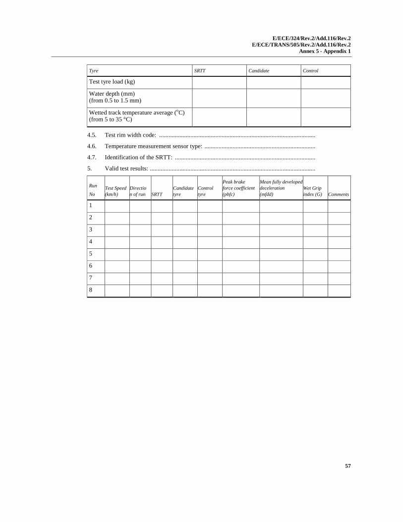
E/ECE/324/Rev.2/Add.116/Rev.2 E/ECE/TRANS/505/Rev.2/Add.116/Rev.2
Annex 5 - Appendix 1
57
Tyre SRTT Candidate Control
Test tyre load (kg)
Water depth (mm) (from 0.5 to 1.5 mm)
Wetted track temperature average (oC) (from 5 to 35 °C)
4.5. Test rim width code: ....................................................................................................
4.6. Temperature measurement sensor type: .......................................................................
4.7. Identification of the SRTT: ..........................................................................................
5. Valid test results: ..........................................................................................................
Run
No Test Speed (km/h)
Direction of run SRTT
Candidate tyre
Control tyre
Peak brake force coefficient (pbfc)
Mean fully developed deceleration (mfdd)
Wet Grip index (G) Comments
1
2
3
4
5
6
7
8
E/ECE/324/Rev.2/Add.116/Rev.2 E/ECE/TRANS/505/Rev.2/Add.116/Rev.2 Annex 6
58
Annex 6
Test procedure for measuring rolling resistance
1. Test Methods
The alternative measurement methods listed below are given in this Regulation. The choice of an individual method is left to the tester. For each method, the test measurements shall be converted to a force acting at the tyre/drum interface. The measured parameters are:
a) In the force method: the reaction force measured or converted at the tyre spindle1;
b) In the torque method: the torque input measured at the test drum2;
c) In the deceleration method: the measurement of deceleration of the test drum and tyre assembly2;
d) In the power method: the measurement of the power input to the test drum2.
2. Test Equipment
2.1. Drum specifications
2.1.1. Diameter
The test dynamometer shall have a cylindrical flywheel (drum) with a diameter of at least 1.7 m.
The Fr and Cr values shall be expressed relative to a drum diameter of 2.0 m. If drum diameter different than 2.0 m is used, a correlation adjustment shall be made following the method in paragraph 6.3.
2.1.2. Surface
The surface of the drum shall be smooth steel. Alternatively, in order to improve skim test reading accuracy, a textured surface may also be used, which should be kept clean.
The Fr and Cr values shall be expressed relative to the "smooth" drum surface. If a textured drum surface is used, see Appendix 1, paragraph 7.
2.1.3. Width
The width of the drum test surface shall exceed the width of the test tyre contact patch.
1 This measured value also includes the bearing and aerodynamic losses of the wheel and tyre which are also to be considered for further data interpretation.
2 The measured value in the torque, deceleration and power methods also includes the bearing and aerodynamic losses of the wheel, the tyre, and the drum which are also to be considered for further data interpretation.
E/ECE/324/Rev.2/Add.116/Rev.2 E/ECE/TRANS/505/Rev.2/Add.116/Rev.2
Annex 6
59
2.2. Measuring rim
The tyre shall be mounted on a steel or light alloy measuring rim, as follows:
(a) For Class C1 and C2 tyres, the width of the rim shall be as defined in ISO 4000-1:2010;
(b) For Class C3 tyres, the width of the rim shall be as defined in ISO 4209 1:2001. No other rim width shall be allowed. See Appendix 2.
2.3. Load, alignment, control and instrumentation accuracies
Measurement of these parameters shall be sufficiently accurate and precise to provide the required test data. The specific and respective values are shown in Appendix 1.
2.4. Thermal environment
2.4.1. Reference conditions
The reference ambient temperature, measured at a distance not less than 0.15 m and not more than 1 m from the tyre sidewall, shall be 25 °C.
2.4.2. Alternative conditions
If the test ambient temperature is different from the reference ambient temperature, the rolling resistance measurement shall be corrected to the reference ambient temperature in accordance with paragraph 6.2. of this annex.
2.4.3. Drum surface temperature.
Care should be taken to ensure that the temperature of the test drum surface is the same as the ambient temperature at the beginning of the test.
3. Test Conditions
3.1. General
The test consists of a measurement of rolling resistance in which the tyre is inflated and the inflation pressure allowed to build up, i.e., "capped air".
3.2. Test speeds
The value shall be obtained at the appropriate drum speed specified in Table 1.
Table 1 Test Speeds (in km/h)
Tyre Class C1 C2 and C3 C3
Load Index All LI ≤ 121 LI > 121
Speed Symbol
All All J 100 km/h and lower or tyres not marked with speed symbol
K 110 km/h and higher
Speed 80 80 60 80
E/ECE/324/Rev.2/Add.116/Rev.2 E/ECE/TRANS/505/Rev.2/Add.116/Rev.2 Annex 6
60
3.3. Test load
The standard test load shall be computed from the values shown in Table 2 and shall be kept within the tolerance specified in Appendix 1.
3.4. Test inflation pressure
The inflation pressure shall be in accordance with that shown in Table 2 and shall be capped with the accuracy specified in paragraph 4. of Appendix 1 to this annex.
Table 2 Test Loads and Inflation Pressures
Tyre Class C1 (a) C2, C3
Standard Load
Reinforced or Extra Load
Load- % of maximum load capacity
80
80
85(b)
(% of single load)
Inflationpressure kPa
210
250
Corresponding to maximum load capacity for single application(c)
Note: The inflation pressure shall be capped with the accuracy specified in paragraph 4 of Appendix 1 to this annex.
(a) For those passenger car tyres belonging to categories which are not shown in ISO 4000-1:2010, the inflation pressure shall be the inflation pressure recommended by the tyre manufacturer, corresponding to the maximum tyre load capacity, reduced by 30 kPa.
(b) As a percentage of single load, or 85 per cent of maximum load capacity for single application specified in applicable tyre standards manuals if not marked on tyre.
(c) Inflation pressure marked on sidewall, or if not marked on sidewall, as specified in applicable tyre standards manuals corresponding to maximum load capacity for single application.
3.5. Duration and speed
When the deceleration method is selected, the following requirements apply:
a) For duration ∆t , the time increments shall not exceed 0.5 s;
b) Any variation of the test drum speed shall not exceed 1 km/h within one time increment.
4. Test Procedure
4.1. General
The test procedure steps described below shall be followed in the sequence given.
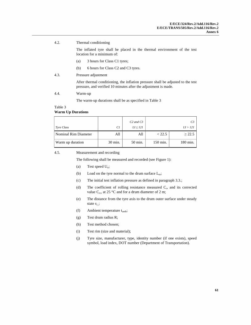
E/ECE/324/Rev.2/Add.116/Rev.2 E/ECE/TRANS/505/Rev.2/Add.116/Rev.2
Annex 6
61
4.2. Thermal conditioning
The inflated tyre shall be placed in the thermal environment of the test location for a minimum of:
(a) 3 hours for Class C1 tyres;
(b) 6 hours for Class C2 and C3 tyres.
4.3. Pressure adjustment
After thermal conditioning, the inflation pressure shall be adjusted to the test pressure, and verified 10 minutes after the adjustment is made.
4.4. Warm-up
The warm-up durations shall be as specified in Table 3
Table 3 Warm Up Durations
Tyre Class C1
C2 and C3
LI ≤ 121
C3
LI > 121
Nominal Rim Diameter All All < 22.5 ≥ 22.5
Warm up duration 30 min. 50 min. 150 min. 180 min.
4.5. Measurement and recording
The following shall be measured and recorded (see Figure 1):
(a) Test speed Un;
(b) Load on the tyre normal to the drum surface Lm;
(c) The initial test inflation pressure as defined in paragraph 3.3.;
(d) The coefficient of rolling resistance measured Cr, and its corrected value Crc, at 25 °C and for a drum diameter of 2 m;
(e) The distance from the tyre axis to the drum outer surface under steady state rL,;
(f) Ambient temperature tamb;
(g) Test drum radius R;
(h) Test method chosen;
(i) Test rim (size and material);
(j) Tyre size, manufacturer, type, identity number (if one exists), speed symbol, load index, DOT number (Department of Transportation).
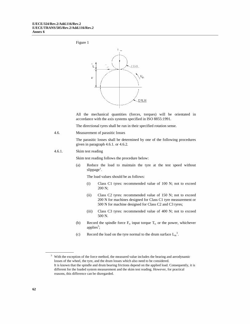
E/ECE/324/Rev.2/Add.116/Rev.2 E/ECE/TRANS/505/Rev.2/Add.116/Rev.2 Annex 6
62
Figure 1
All the mechanical quantities (forces, torques) will be orientated in accordance with the axis systems specified in ISO 8855:1991.
The directional tyres shall be run in their specified rotation sense.
4.6. Measurement of parasitic losses
The parasitic losses shall be determined by one of the following procedures given in paragraph 4.6.1. or 4.6.2.
4.6.1. Skim test reading
Skim test reading follows the procedure below:
(a) Reduce the load to maintain the tyre at the test speed without slippage3.
The load values should be as follows:
(i) Class C1 tyres: recommended value of 100 N; not to exceed 200 N;
(ii) Class C2 tyres: recommended value of 150 N; not to exceed 200 N for machines designed for Class C1 tyre measurement or 500 N for machine designed for Class C2 and C3 tyres;
(iii) Class C3 tyres: recommended value of 400 N; not to exceed 500 N.
(b) Record the spindle force Ft, input torque Tt, or the power, whichever applies3;
(c) Record the load on the tyre normal to the drum surface Lm3.
3 With the exception of the force method, the measured value includes the bearing and aerodynamic losses of the wheel, the tyre, and the drum losses which also need to be considered.
It is known that the spindle and drum bearing frictions depend on the applied load. Consequently, it is different for the loaded system measurement and the skim test reading. However, for practical reasons, this difference can be disregarded.
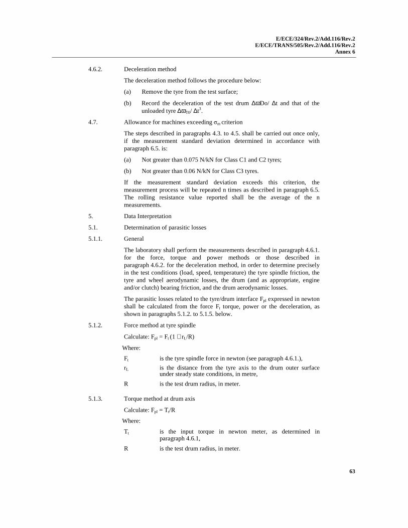
E/ECE/324/Rev.2/Add.116/Rev.2 E/ECE/TRANS/505/Rev.2/Add.116/Rev.2
Annex 6
63
4.6.2. Deceleration method
The deceleration method follows the procedure below:
(a) Remove the tyre from the test surface;
(b) Record the deceleration of the test drum ∆ωDo/ ∆t and that of the unloaded tyre ∆ωT0/ ∆t3.
4.7. Allowance for machines exceeding σm criterion
The steps described in paragraphs 4.3. to 4.5. shall be carried out once only, if the measurement standard deviation determined in accordance with paragraph 6.5. is:
(a) Not greater than 0.075 N/kN for Class C1 and C2 tyres;
(b) Not greater than 0.06 N/kN for Class C3 tyres.
If the measurement standard deviation exceeds this criterion, the measurement process will be repeated n times as described in paragraph 6.5. The rolling resistance value reported shall be the average of the n measurements.
5. Data Interpretation
5.1. Determination of parasitic losses
5.1.1. General
The laboratory shall perform the measurements described in paragraph 4.6.1. for the force, torque and power methods or those described in paragraph 4.6.2. for the deceleration method, in order to determine precisely in the test conditions (load, speed, temperature) the tyre spindle friction, the tyre and wheel aerodynamic losses, the drum (and as appropriate, engine and/or clutch) bearing friction, and the drum aerodynamic losses.
The parasitic losses related to the tyre/drum interface Fpl expressed in newton shall be calculated from the force Ft torque, power or the deceleration, as shown in paragraphs 5.1.2. to 5.1.5. below.
5.1.2. Force method at tyre spindle
Calculate: Fpl = Ft (1 + rL/R)
Where:
Ft is the tyre spindle force in newton (see paragraph 4.6.1.),
rL is the distance from the tyre axis to the drum outer surface under steady state conditions, in metre,
R is the test drum radius, in meter.
5.1.3. Torque method at drum axis
Calculate: Fpl = Tt/R
Where:
Tt is the input torque in newton meter, as determined in paragraph 4.6.1,
R is the test drum radius, in meter.
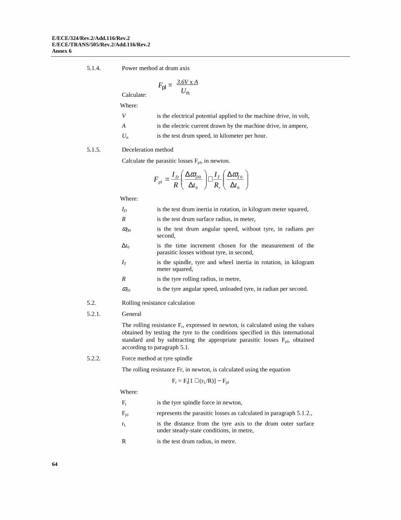
E/ECE/324/Rev.2/Add.116/Rev.2 E/ECE/TRANS/505/Rev.2/Add.116/Rev.2 Annex 6
64
5.1.4. Power method at drum axis
Calculate: pl
n
3,6V AF
U
×=
Where:
V is the electrical potential applied to the machine drive, in volt,
A is the electric current drawn by the machine drive, in ampere,
Un is the test drum speed, in kilometer per hour.
5.1.5. Deceleration method
Calculate the parasitic losses Fpl, in newton.
∆∆
+
∆∆
=0
0
0
0
tR
I
tR
IF T
r
TDDpl
ωω
Where:
ID is the test drum inertia in rotation, in kilogram meter squared,
R is the test drum surface radius, in meter,
ωD0 is the test drum angular speed, without tyre, in radians per second,
∆t0 is the time increment chosen for the measurement of the parasitic losses without tyre, in second,
IT is the spindle, tyre and wheel inertia in rotation, in kilogram meter squared,
R is the tyre rolling radius, in metre,
ωT0 is the tyre angular speed, unloaded tyre, in radian per second.
5.2. Rolling resistance calculation
5.2.1. General
The rolling resistance Fr, expressed in newton, is calculated using the values obtained by testing the tyre to the conditions specified in this international standard and by subtracting the appropriate parasitic losses Fpl, obtained according to paragraph 5.1.
5.2.2. Force method at tyre spindle
The rolling resistance Fr, in newton, is calculated using the equation
Fr = Ft[1 + (rL/R)] − Fpl
Where:
Ft is the tyre spindle force in newton,
Fpl represents the parasitic losses as calculated in paragraph 5.1.2.,
rL is the distance from the tyre axis to the drum outer surface under steady-state conditions, in metre,
R is the test drum radius, in metre.
3.6V x A
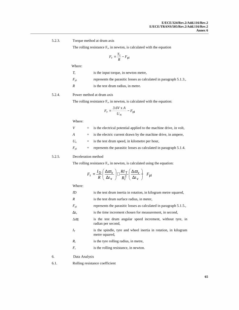
E/ECE/324/Rev.2/Add.116/Rev.2 E/ECE/TRANS/505/Rev.2/Add.116/Rev.2
Annex 6
65
5.2.3. Torque method at drum axis
The rolling resistance Fr, in newton, is calculated with the equation
tr pl
TF F
R= −
Where:
Tt is the input torque, in newton metre,
Fpl represents the parasitic losses as calculated in paragraph 5.1.3.,
R is the test drum radius, in metre.
5.2.4. Power method at drum axis
The rolling resistance Fr, in newton, is calculated with the equation:
r pln
3,6V AF F
U
×= −
Where:
V = is the electrical potential applied to the machine drive, in volt,
A = is the electric current drawn by the machine drive, in ampere,
Un = is the test drum speed, in kilometre per hour,
Fpl = represents the parasitic losses as calculated in paragraph 5.1.4.
5.2.5. Deceleration method
The rolling resistance Fr, in newton, is calculated using the equation:
2D ν T ν
r plν νr
I RIF F
R t tR
ω ω ∆ ∆= + − ∆ ∆
Where:
ID is the test drum inertia in rotation, in kilogram metre squared,
R is the test drum surface radius, in meter,
Fpl represents the parasitic losses as calculated in paragraph 5.1.5.,
∆tv is the time increment chosen for measurement, in second,
∆ωv is the test drum angular speed increment, without tyre, in radian per second,
IT is the spindle, tyre and wheel inertia in rotation, in kilogram metre squared,
Rr is the tyre rolling radius, in metre,
Fr is the rolling resistance, in newton.
6. Data Analysis
6.1. Rolling resistance coefficient
3.6V x A
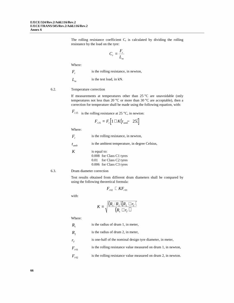
E/ECE/324/Rev.2/Add.116/Rev.2 E/ECE/TRANS/505/Rev.2/Add.116/Rev.2 Annex 6
66
The rolling resistance coefficient Cr is calculated by dividing the rolling resistance by the load on the tyre:
CF
Lrr
m
=
Where:
Fr is the rolling resistance, in newton,
Lm is the test load, in kN.
6.2. Temperature correction
If measurements at temperatures other than 25 °C are unavoidable (only temperatures not less than 20 °C or more than 30 °C are acceptable), then a correction for temperature shall be made using the following equation, with:
Fr25 is the rolling resistance at 25 °C, in newton:
( )[ ]F F K tr r amb25 1 25= + −
Where:
Fr is the rolling resistance, in newton,
tamb is the ambient temperature, in degree Celsius,
K is equal to: 0.008 for Class C1 tyres 0.01 for Class C2 tyres 0.006 for Class C3 tyres
6.3. Drum diameter correction
Test results obtained from different drum diameters shall be compared by using the following theoretical formula:
F KFr r02 01≅
with:
) )(()( T
T
rR
rRRRK
++=
1
221
Where:
R1 is the radius of drum 1, in meter,
R2 is the radius of drum 2, in meter,
rT is one-half of the nominal design tyre diameter, in meter,
01rF
is the rolling resistance value measured on drum 1, in newton,
Fr02 is the rolling resistance value measured on drum 2, in newton.
E/ECE/324/Rev.2/Add.116/Rev.2 E/ECE/TRANS/505/Rev.2/Add.116/Rev.2
Annex 6
67
6.4. Measurement result
Where n measurements are greater than 1, if required by paragraph 4.6., the measurement result shall be the average of the Cr values obtained for the n measurements, after the corrections described in paragraphs 6.2. and 6.3. have been made.
6.5. The laboratory shall ensure that, based on a minimum of three measurements, the machine maintains the following values of σm, as measured on a single tyre:
σm ≤ 0.075 N/kN for tyres of Classes C1 and C2
σm ≤ 0.06 N/kN for tyres of Class C3
If the above requirement for σm is not met, the following formula shall be applied to determine the minimum number of measurements n (rounded to the immediate superior integer value) that are required by the machine to qualify for conformance with this Regulation.
n = (σm/ x)²
Where:
x = 0.075 N/kN for tyres of Classes C1 and C2
x = 0.06 N/kN for tyres of Class C3
If a tyre needs to be measured several times, the tyre/wheel assembly shall be removed from the machine between the successive measurements.
If the removal/refitting operation duration is less than 10 minutes, the warm-up durations indicated in paragraph 4.3. may be reduced to:
(a) 10 minutes for tyres of Class C1;
(b) 20 minutes for tyres of Class C2;
(c) 30 minutes for tyres of Class C3.
6.6. Monitoring of the laboratory control tyre shall be carried out at intervals no greater than one month. Monitoring shall include a minimum of 3 separate measurements taken during this one month period. The average of the 3 measurements taken during a given one-month period shall be evaluated for drift from one monthly evaluation to another.
E/ECE/324/Rev.2/Add.116/Rev.2 E/ECE/TRANS/505/Rev.2/Add.116/Rev.2 Annex 6 - Appendix 1
68
Annex 6
Appendix 1
Test equipment tolerances
1. Purpose
The limits specified in this annex are necessary in order to achieve suitable levels of repeatable test results, which can also be correlated among various test laboratories. These tolerances are not meant to represent a complete set of engineering specifications for test equipment; rather, they should serve as guidelines for achieving reliable test results.
2. Test rims
2.1. Width
For passenger car tyre rims (C1 tyres), the test rim width shall be the same as the measuring rim determined in ISO 4000-1: 2010 clause 6.2.2.
For truck and bus tyres (C2 and C3), the rim width shall be the same as the measuring rim determined ISO 4209-1:2001 clause 5.1.3.
2.2. Run-out
Run-out shall meet the following criteria:
(a) Maximum radial run-out: 0.5 mm;
(b) Maximum lateral run-out: 0.5 mm.
3. Drum / tyre alignment
General:
Angle deviations are critical to the test results.
3.1. Load application
The direction of tyre loading application shall be kept normal to the test surface and shall pass through the wheel centre within
(a) 1 mrad for the force and deceleration methods;
(b) 5 mrad for the torque and power methods.
3.2. Tyre alignment
3.2.1. Camber angle
The plane of the wheel shall be perpendicular to the test surface within 2 mrad for all methods.
3.2.2. Slip angle
The plane of the tyre shall be parallel to the direction of the test surface motion within 1 mrad for all methods.
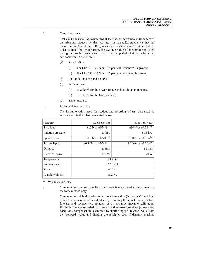
E/ECE/324/Rev.2/Add.116/Rev.2 E/ECE/TRANS/505/Rev.2/Add.116/Rev.2
Annex 6 - Appendix 1
69
4. Control accuracy
Test conditions shall be maintained at their specified values, independent of perturbations induced by the tyre and rim non-uniformity, such that the overall variability of the rolling resistance measurement is minimized. In order to meet this requirement, the average value of measurements taken during the rolling resistance data collection period shall be within the accuracies stated as follows:
(a) Tyre loading:
(i) For LI ≤ 121 ±20 N or ±0.5 per cent, whichever is greater;
(ii) For LI > 121 ±45 N or ±0.5 per cent whichever is greater;
(b) Cold inflation pressure: ±3 kPa;
(c) Surface speed:
(i) ±0.2 km/h for the power, torque and deceleration methods;
(ii) ±0.5 km/h for the force method;
(d) Time: ±0.02 s.
5. Instrumentation accuracy
The instrumentation used for readout and recording of test data shall be accurate within the tolerances stated below:
Parameter Load Index ≤ 121 Load Index > 121
Tyre load ±10 N or ±0.5 % (a) ±30 N or ±0.5 % (a)
Inflation pressure ±1 kPa ±1.5 kPa
Spindle force ±0.5 N or +0.5 % (a) ±1.0 N or +0.5 % (a)
Torque input ±0.5 Nm or +0.5 % (a) ±1.0 Nm or +0.5 % (a)
Distance ±1 mm ±1 mm
Electrical power ±10 W ±20 W
Temperature ±0.2 °C
Surface speed ±0.1 km/h
Time ±0.01 s
Angular velocity ±0.1 %
(a) Whichever is greater.
6. Compensation for load/spindle force interaction and load misalignment for the force method only
Compensation of both load/spindle force interaction ("cross talk") and load misalignment may be achieved either by recording the spindle force for both forward and reverse tyre rotation or by dynamic machine calibration. If spindle force is recorded for forward and reverse directions (at each test condition), compensation is achieved by subtracting the "reverse" value from the "forward" value and dividing the result by two. If dynamic machine
E/ECE/324/Rev.2/Add.116/Rev.2 E/ECE/TRANS/505/Rev.2/Add.116/Rev.2 Annex 6 - Appendix 1
70
calibration is intended, the compensation terms may be easily incorporated in the data reduction.
In cases where reverse tyre rotation immediately follows the completion of the forward tyre rotation, a warm-up time for reverse tyre rotation shall be at least 10 minutes for Class C1 tyres and 30 minutes for all other tyre types.
7. Test surface roughness
The roughness, measured laterally, of the smooth steel drum surface shall have a maximum centreline average height value of 6.3 µm1.
Note: In cases where a textured drum surface is used instead of a smooth steel surface, this fact is noted in the test report. The surface texture shall then be 180 µm deep (80 grit) and the laboratory is responsible for maintaining the surface roughness characteristics. No specific correction factor is recommended for cases where a textured drum surface is used.
1 In cases where a textured drum surface is used instead of a smooth steel surface, this fact is noted in the test report. The surface texture shall then be 180 µm deep (80 grit) and the laboratory is responsible for maintaining the surface roughness characteristics. No specific correction factor is recommended for cases where a textured drum surface is used.
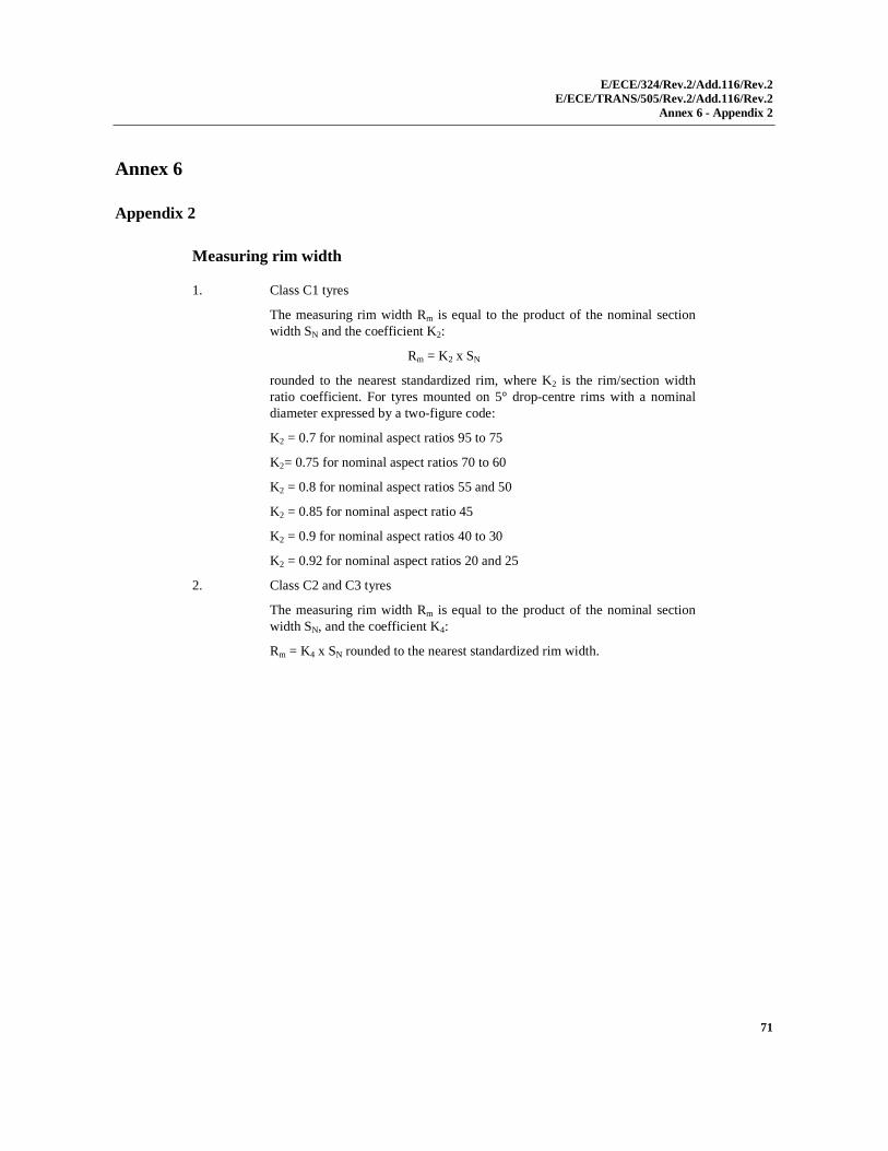
E/ECE/324/Rev.2/Add.116/Rev.2 E/ECE/TRANS/505/Rev.2/Add.116/Rev.2
Annex 6 - Appendix 2
71
Annex 6
Appendix 2
Measuring rim width
1. Class C1 tyres
The measuring rim width Rm is equal to the product of the nominal section width SN and the coefficient K2:
Rm = K2 x SN
rounded to the nearest standardized rim, where K2 is the rim/section width ratio coefficient. For tyres mounted on 5° drop-centre rims with a nominal diameter expressed by a two-figure code:
K2 = 0.7 for nominal aspect ratios 95 to 75
K2= 0.75 for nominal aspect ratios 70 to 60
K2 = 0.8 for nominal aspect ratios 55 and 50
K2 = 0.85 for nominal aspect ratio 45
K2 = 0.9 for nominal aspect ratios 40 to 30
K2 = 0.92 for nominal aspect ratios 20 and 25
2. Class C2 and C3 tyres
The measuring rim width Rm is equal to the product of the nominal section width SN, and the coefficient K4:
Rm = K4 x SN rounded to the nearest standardized rim width.
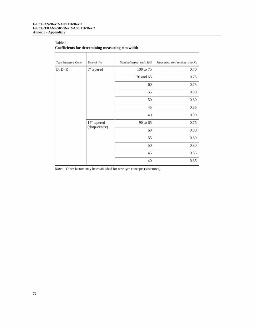
E/ECE/324/Rev.2/Add.116/Rev.2 E/ECE/TRANS/505/Rev.2/Add.116/Rev.2 Annex 6 - Appendix 2
72
Table 1 Coefficients for determining measuring rim width
Tyre Structure Code Type of rim Nominal aspect ratio H/S Measuring rim/ section ratio K4
100 to 75 0.70
70 and 65 0.75
60 0.75
55 0.80
50 0.80
45 0.85
5º tapered
40 0.90
90 to 65 0.75
60 0.80
55 0.80
50 0.80
45 0.85
B, D, R
15º tapered (drop-centre)
40 0.85
Note: Other factors may be established for new tyre concepts (structures).
E/ECE/324/Rev.2/Add.116/Rev.2 E/ECE/TRANS/505/Rev.2/Add.116/Rev.2
Annex 6 - Appendix 3
73
Annex 6
Appendix 3
Test report and Test data (Rolling resistance)
Part 1: Report
1. Type Approval authority or Technical Service: ................................................
2. Name and address of applicant: ........................................................................
3. Test report No.:..................................................................................................
4. Manufacturer and brand name or trade description: .........................................
5. Tyre class (C1, C2 or C3): ................................................................................
6. Category of use: ................................................................................................
7. Rolling resistance coefficient (temperature and drum diameter corrected): .....................................................
8. Comments (if any): ...........................................................................................
9. Date: .................................................................................................................
10. Signature: ..........................................................................................................
Part 2: Test data
1. Date of test: .......................................................................................................
2. Test machine identification and drum diameter/surface: ..................................
3. Test tyre details: ................................................................................................
3.1. Tyre size designation and service description: .................................................
3.2. Tyre brand and trade description: .....................................................................
3.3. Reference inflation pressure: ......................................................................kPa
4. Test data: ...........................................................................................................
4.1. Measurement method: ......................................................................................
4.2. Test speed: ...............................................................................................km/h
4.3. Load: ............................................................................................................. N
4.4. Test inflation pressure, initial: ..........................................................................
4.5. Distance from the tyre axis to the drum outer surface under steady state conditions, rL: ................................................................................................ m
4.6. Test rim width and material: .............................................................................
4.7. Ambient temperature: .................................................................................. °C
4.8. Skim test load (except deceleration method): ............................................... N
5. Rolling resistance coefficient: ..........................................................................
5.1. Initial value (or average in the case of more than 1): ...............................N/kN
5.2. Temperature corrected N/kN: ...........................................................................
5.3. Temperature and drum diameter corrected: .............................................N/kN
E/ECE/324/Rev.2/Add.116/Rev.2 E/ECE/TRANS/505/Rev.2/Add.116/Rev.2 Annex 7
74
Annex 7
Procedures for snow performance testing
1. Specific definitions for snow test when different of existing ones
1.1. "Test run" means a single pass of a loaded tyre over a given test surface.
1.2. "Braking test" means a series of a specified number of ABS-braking test runs of the same tyre repeated within a short time frame.
1.3. "Traction test" means a series of a specified number of spin-traction test runs according to ASTM standard F1805-06 of the same tyre repeated within a short time frame.
2. Spin traction method for Class C1 and C2 tyres
The test procedure of ASTM standard F1805-06 shall be used to assess snow performance through spin traction values on medium packed snow (The snow compaction index measured with a CTI penetrometer1 shall be between 70 and 80).
2.1. The test course surface shall be composed of a medium packed snow surface, as characterized in table A2.1 of ASTM standard F1805-06.
2.2. The tyre load for testing shall be as per option 2 in paragraph 11.9.2. of ASTM standard F1805-06.
3. Braking on snow method for Class C1 tyres
3.1. General conditions
3.1.1. Test course
The braking tests shall be done on a flat test surface of sufficient length and width, with a maximum 2 per cent gradient, covered with packed snow.
The snow surface shall be composed of a hard packed snow base at least 3 cm thick and a surface layer of medium packed and prepared snow about 2 cm thick.
Both air temperature, measured about one meter above the ground, and snow temperature, measured at a depth of about one centimetre, shall be between -2 °C and -15 °C.
It is recommended to avoid direct sunlight, large variations of sunlight or humidity, as well as wind.
The snow compaction index measured with a CTI penetrometer1 shall be between 75 and 85.
3.1.2. Vehicle
The test shall be conducted with a standard production passenger car in good running order and equipped with an ABS system.
1 See appendix of ASTM standard F1805-06 for details.
E/ECE/324/Rev.2/Add.116/Rev.2 E/ECE/TRANS/505/Rev.2/Add.116/Rev.2
Annex 7
75
The vehicle used shall be such that the loads on each wheel are appropriate to the tyres being tested. Several different tyre sizes can be tested on the same vehicle.
3.1.3. Tyres
Tyres shall be trimmed, and broken-in prior to testing by driving at least 100 km on dry pavement. The tyre surface in contact with snow shall be cleaned before performing a test.
Tyres shall be conditioned at the outdoor ambient temperature at least two hours before their mounting for tests. Tyre pressures shall then be adjusted to the values specified for the test.
In case a vehicle cannot accommodate both the reference and candidate tyres, a third tyre ("control" tyre) may be used as an intermediate. First test control vs. reference on another vehicle, then test candidate vs. control on the vehicle.
3.1.4. Load and pressure
The vehicle load shall be such that the resulting loads on the tyres are between 60 per cent and 90 per cent of the load corresponding to the tyre load index.
The cold inflation pressure shall be 240 kPa.
3.1.5. Instrumentation
The vehicle shall be fitted with calibrated sensors suitable for measurements in winter. There shall be a data acquisition system to store measurements.
The accuracy of measurement sensors and systems shall be such that the relative uncertainty of the measured or computed mean fully developed decelerations is less than 1 per cent.
3.2. Testing sequences
3.2.1. For every candidate tyre and the standard reference tyre, ABS-braking test runs shall be repeated a minimum of 6 times.
The zones where ABS-braking is fully applied shall not overlap.
When a new set of tyres is tested, the runs are performed after shifting aside the vehicle trajectory in order not to brake on the tracks of the previous tyre.
When it is no longer possible not to overlap full ABS-braking zones, the test course shall be re-groomed.
Required sequence:
6 repeats SRTT, then shift aside to test next tyre on fresh surface
6 repeats Candidate 1, then shift aside
6 repeats Candidate 2, then shift aside
6 repeats SRTT, then shift aside
E/ECE/324/Rev.2/Add.116/Rev.2 E/ECE/TRANS/505/Rev.2/Add.116/Rev.2 Annex 7
76
3.2.2. Order of testing:
If only one candidate tyre is to be evaluated, the order of testing shall be:
R1 - T - R2
Where:
R1 is the initial test of the SRTT, R2 is the repeat test of the SRTT and T is the test of the candidate tyre to be evaluated.
A maximum of two candidate tyres may be tested before repeating the SRTT test, for example:
R1 - T1 - T2 - R2.
3.2.3. The comparative tests of SRTT and candidate tyres shall be repeated on two different days.
3.3. Test procedure
3.3.1. Drive the vehicle at a speed not lower than 28 km/h.
3.3.2. When the measuring zone has been reached, the vehicle gear is set into neutral, the brake pedal is depressed sharply by a constant force sufficient to cause operation of the ABS on all wheels of the vehicle and to result in stable deceleration of the vehicle and held down until the speed is lower than 8 km/h.
3.3.3. The mean fully developed deceleration between 25 km/h and 10 km/h shall be computed from time, distance, speed, or acceleration measurements.
3.4. Data evaluation and presentation of results
3.4.1. Parameters to be reported
3.4.1.1. For each tyre and each braking test, the mean and standard deviation of the mfdd shall be computed and reported.
The coefficient of variation CV of a tyre braking test shall be computed as:
( ) ( )( )tyreMean
tyredevStdtyreCV
.=
3.4.1.2 Weighted averages of two successive tests of the SRTT shall be computed taking into account the number of candidate tyres in between:
In the case of the order of testing R1 - T - R2, the weighted average of the SRTT to be used in the comparison of the performance of the candidate tyre shall be taken to be:
wa(SRTT) = (R1 + R2)/2
Where:
R1 is the mean mfdd for the first test of the SRTT and R2 is the mean mfdd for the second test of the SRTT.
In the case of the order of testing R1 – T1 – T2 – R2, the weighted average (wa) of the SRTT to be used in the comparison of the performance of the candidate tyre shall be taken to be:
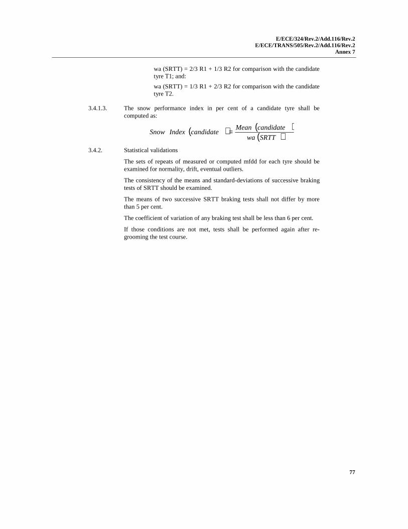
E/ECE/324/Rev.2/Add.116/Rev.2 E/ECE/TRANS/505/Rev.2/Add.116/Rev.2
Annex 7
77
wa (SRTT) = 2/3 R1 + 1/3 R2 for comparison with the candidate tyre T1; and:
wa (SRTT) = 1/3 R1 + 2/3 R2 for comparison with the candidate tyre T2.
3.4.1.3. The snow performance index in per cent of a candidate tyre shall be computed as:
( ) ( )( )SRTTwa
candidateMeancandidateIndexSnow =
3.4.2. Statistical validations
The sets of repeats of measured or computed mfdd for each tyre should be examined for normality, drift, eventual outliers.
The consistency of the means and standard-deviations of successive braking tests of SRTT should be examined.
The means of two successive SRTT braking tests shall not differ by more than 5 per cent.
The coefficient of variation of any braking test shall be less than 6 per cent.
If those conditions are not met, tests shall be performed again after re-grooming the test course.
E/ECE/324/Rev.2/Add.116/Rev.2 E/ECE/TRANS/505/Rev.2/Add.116/Rev.2 Annex 7 - Appendix 1
78
Annex 7
Appendix 1
Pictogram definition of "Alpine Symbol"
Minimum 15 mm base and 15 mm height, placed adjacent to the M+S inscription, if marked.
Above drawing not to scale.
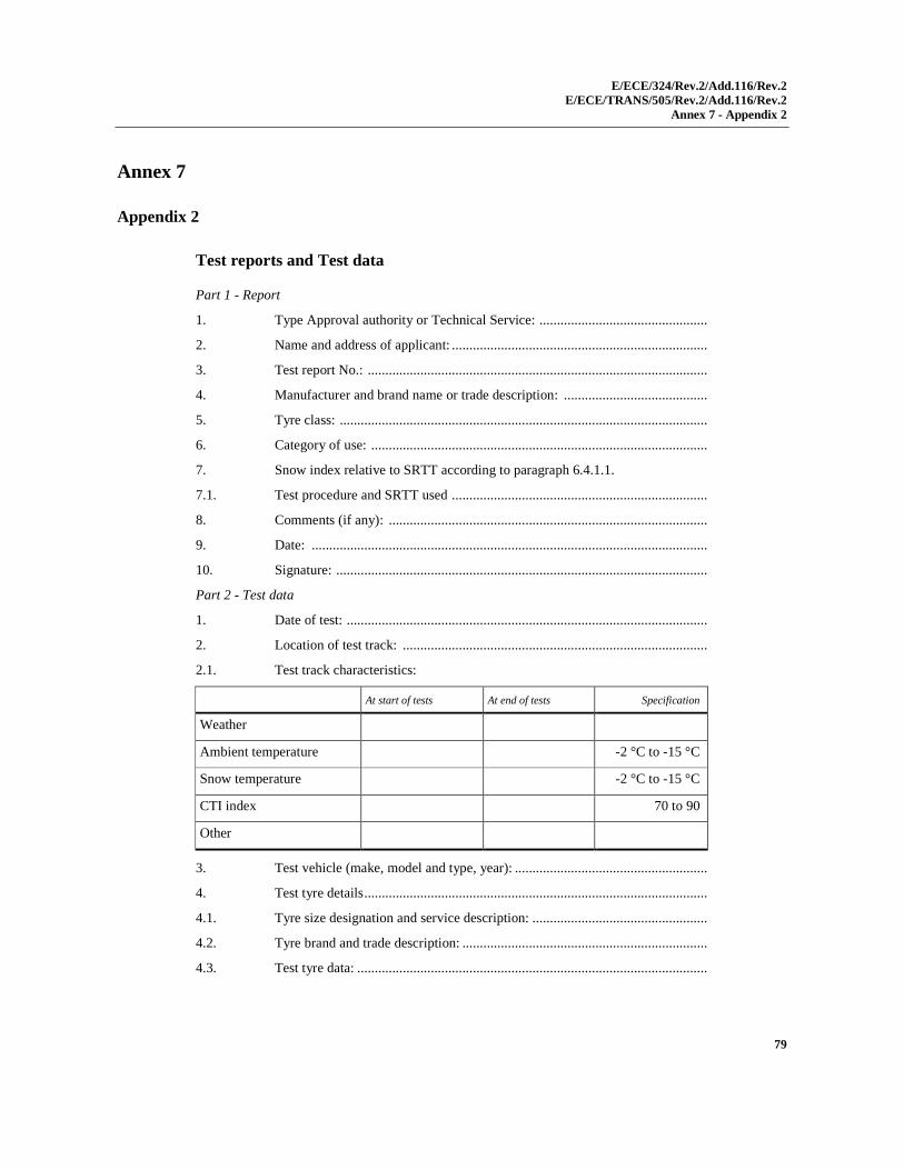
E/ECE/324/Rev.2/Add.116/Rev.2 E/ECE/TRANS/505/Rev.2/Add.116/Rev.2
Annex 7 - Appendix 2
79
Annex 7
Appendix 2
Test reports and Test data
Part 1 - Report
1. Type Approval authority or Technical Service: ................................................
2. Name and address of applicant: .........................................................................
3. Test report No.: .................................................................................................
4. Manufacturer and brand name or trade description: .........................................
5. Tyre class: .........................................................................................................
6. Category of use: ................................................................................................
7. Snow index relative to SRTT according to paragraph 6.4.1.1.
7.1. Test procedure and SRTT used .........................................................................
8. Comments (if any): ...........................................................................................
9. Date: .................................................................................................................
10. Signature: ..........................................................................................................
Part 2 - Test data
1. Date of test: .......................................................................................................
2. Location of test track: .......................................................................................
2.1. Test track characteristics:
At start of tests At end of tests Specification
Weather
Ambient temperature -2 °C to -15 °C
Snow temperature -2 °C to -15 °C
CTI index 70 to 90
Other
3. Test vehicle (make, model and type, year): .......................................................
4. Test tyre details..................................................................................................
4.1. Tyre size designation and service description:..................................................
4.2. Tyre brand and trade description: ......................................................................
4.3. Test tyre data: ....................................................................................................
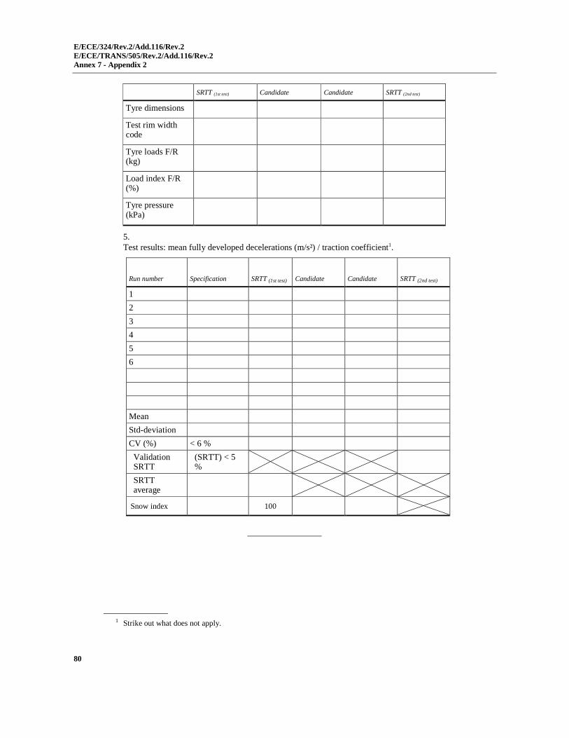
E/ECE/324/Rev.2/Add.116/Rev.2 E/ECE/TRANS/505/Rev.2/Add.116/Rev.2 Annex 7 - Appendix 2
80
SRTT (1st test) Candidate Candidate SRTT (2nd test)
Tyre dimensions
Test rim width code
Tyre loads F/R (kg)
Load index F/R (%)
Tyre pressure (kPa)
5. Test results: mean fully developed decelerations (m/s²) / traction coefficient1.
Run number Specification SRTT (1st test) Candidate Candidate
SRTT (2nd test)
1
2
3
4
5
6
Mean
Std-deviation
CV (%) < 6 %
Validation SRTT
(SRTT) < 5 %
SRTT average
Snow index 100
1 Strike out what does not apply.