agilent 1260 infinity dual-loop autosampler, preparative scale
TRANSCRIPT
Agilent 1260 Infinity Dual-Loop Autosampler, Preparative Scale
User Manual
Agilent 1260 Infinity Dual-Loop Autosampler User’s Guide
Notices© Agilent Technologies, Inc. 2010
No part of this manual may be reproduced in any form or by any means (including elec-tronic storage and retrieval or translation into a foreign language) without prior agree-ment and written consent from Agilent Technologies, Inc. as governed by United States and international copyright laws.
Microsoft ® is a U.S. registered trademark of Microsoft Corporation.
Manual Part NumberG2258-90012
Edition06/10
Printed in Germany
Agilent Technologies Hewlett-Packard-Strasse 8 76337 Waldbronn This product may be used as a com-ponent of an in vitro diagnostic sys-tem if the system is registered with the appropriate authorities and com-plies with the relevant regula-tions. Otherwise, it is intended only for gen-eral laboratory use.
Warranty
The material contained in this docu-ment is provided “as is,” and is sub-ject to being changed, without notice, in future editions. Further, to the max-imum extent permitted by applicable law, Agilent disclaims all warranties, either express or implied, with regard to this manual and any information contained herein, including but not limited to the implied warranties of merchantability and fitness for a par-ticular purpose. Agilent shall not be liable for errors or for incidental or consequential damages in connec-tion with the furnishing, use, or per-formance of this document or of any information contained herein. Should Agilent and the user have a separate written agreement with warranty terms covering the material in this document that conflict with these terms, the warranty terms in the sep-arate agreement shall control.
Technology Licenses The hardware and/or software described in this document are furnished under a license and may be used or copied only in accor-dance with the terms of such license.
Restricted Rights LegendIf software is for use in the performance of a U.S. Government prime contract or subcon-tract, Software is delivered and licensed as “Commercial computer software” as defined in DFAR 252.227-7014 (June 1995), or as a “commercial item” as defined in FAR 2.101(a) or as “Restricted computer soft-ware” as defined in FAR 52.227-19 (June 1987) or any equivalent agency regulation or contract clause. Use, duplication or disclo-sure of Software is subject to Agilent Tech-nologies’ standard commercial license terms, and non-DOD Departments and Agencies of the U.S. Government will
receive no greater than Restricted Rights as defined in FAR 52.227-19(c)(1-2) (June 1987). U.S. Government users will receive no greater than Limited Rights as defined in FAR 52.227-14 (June 1987) or DFAR 252.227-7015 (b)(2) (November 1995), as applicable in any technical data.
Safety Notices
CAUTION
A CAUTION notice denotes a haz-ard. It calls attention to an operat-ing procedure, practice, or the like that, if not correctly performed or adhered to, could result in damage to the product or loss of important data. Do not proceed beyond a CAUTION notice until the indicated conditions are fully understood and met.
WARNING
A WARNING notice denotes a hazard. It calls attention to an operating procedure, practice, or the like that, if not correctly per-formed or adhered to, could result in personal injury or death. Do not proceed beyond a WARNING notice until the indicated condi-tions are fully understood and met.
In This Guide…This manual contains technical reference information about the Agilent 1260 Infinity Dual-Loop Autosampler, preparative scale. The manual describes the following:
1 Introduction to the Dual-Loop ALS
This chapter gives an introduction to the Dual Loop Autosampler.
2 Site Requirements and Specifications
This chapter describes the Site Requirements and Specifications of the Dual Loop Autosampler.
3 Installing the Dual-Loop Autosampler
This chapter describes the Installation of the Dual Loop Autosampler.
4 Using the Dual-Loop Autosampler
This chapter describes the Usage of the Dual Loop Autosampler.
5 Troubleshooting Overview
This chapter gives an Overview to Troubleshooting the Dual Loop Autosampler.
6 Introduction to Repairing the Dual-Loop Autosampler
This chapter gives an Introduction to Repairing the Dual Loop Autosampler.
7 Maintaining the Dual-Loop Autosampler
This chapter describes the Maintenance and Simple Repairs of the Dual Loop Autosampler.
8 Easy Repair Parts
This chapter describes the Consumables and Accessories of the Dual Loop Autosampler.
Agilent 1260 Infinity Dual-Loop Autosampler User’s Guide 3
A Safety Information
This chapter gives Safety Information for the use of the Dual Loop Autosampler.
4 Agilent 1260 Infinity Dual-Loop Autosampler User’s Guide
Contents
Contents
1 Introduction to the Dual-Loop ALS 9
Introduction 10
Front View 11
Theory of Operation 12
The Injection Sequence 16Loop Filling Modes 26
2 Site Requirements and Specifications 29
Site Requirements 30
Power Consideration 30Power Cords 31Bench Space 31Environment 32
Performance Specifications of the Dual-Loop Autosampler 34
Method for Carry-over Test 36
3 Installing the Dual-Loop Autosampler 37
Unpacking the Dual-Loop Autosampler 38
Damaged Packaging 38Delivery Checklist 38Accessory Kits 39
Optimizing the Stack Configuration 42
Analytical System 43Preparative System 45
Installation 47
Installing the Dual-Loop Autosampler 47Installing a Thermostatted Dual-Loop Autosampler 50Flow Connections to the Dual-Loop Autosampler 55
Agilent 1260 Infinity Dual-Loop Autosampler User’s Guide 5
Contents
Flushing the Metering Device 58
Initial Priming by Backflushing with External Pump 58Purging the Syringe 59Flushing the Syringe 60
Configuring Wellplate Types 64
Special Transport Unit Positions 68
Transporting the Dual-Loop Autosampler 68Maintenance Positions 68
4 Using the Dual-Loop Autosampler 69
General Comments about Sample Trays 70
Supported Trays 70Unsupported Trays 70
Operating the Dual-Loop Sampler with Agilent ChemStation 71
Navigation in Agilent ChemStation 71Configuring the Dual-Loop Sampler with ChemStation 72Additional Configuration and Control Functions 74Setting Method Parameters in Agilent ChemStation 76More Method Parameters 79
Achieving the best recovery results with the Agilent 1260 Infinity Dual-Loop Autosampler PS 81
Introduction 81Rinse solvent 81Flush solvent 82Sample draw and eject speed 83Sample loop overfill factor for complete loop filling 83Sample loop fill factor for partial loop fill 84
5 Troubleshooting Overview 85
Overview 86
Status Indicators 86
6 Agilent 1260 Infinity Dual-Loop Autosampler User’s Guide
Contents
Error Messages 86Maintenance Functions 86Transport Unit Self Alignment 86
Status Indicators 88
Power Supply Indicator 88Instrument Status Indicator 89
6 Introduction to Repairing the Dual-Loop Autosampler 91
Introduction to Repairing the Dual-Loop Autosampler 92
Simple Repairs 92Exchanging Internal Parts 92Cleaning the Dual-Loop Autosampler 93Using the ESD Strap 93
7 Maintaining the Dual-Loop Autosampler 95
Maintenance Procedures and Simple Repairs 96
Replacing the Rotor Seal of the 10-Port Valve 97Replacing the Needle Assembly 100Replacing the Buffer Loop 104Replacing Front Seat/Back Seat Assembly or Seat Tubings 108Replacing the Peristaltic Pump 110Exchanging the Needle Carrier Assembly 112Replacing Seal or Piston of the Metering Unit 115Exchanging or Installing the (Optional Interface) BCD Board 120
8 Easy Repair Parts 121
Consumables 122
List of Supported Plate Trays 122List of Recommended Well Plates and Vial Plates 123List of Recommended Vials, Caps and Septa 124Sample Loops for the G2258A 10-port Valve 125
Dual-Loop Autosampler Accessory Kit 126
Agilent 1260 Infinity Dual-Loop Autosampler User’s Guide 7
Contents
A Safety Information 129
Safety Information 130
General 130Operation 131Safety Symbols 132
Lithium Batteries Information 133
Radio Interference 134
Test and Measurement 134
Sound Emission 135
Manufacturer’s Declaration 135
Solvent Information 136
Solvents 136
Agilent Technologies on Internet 137
8 Agilent 1260 Infinity Dual-Loop Autosampler User’s Guide
Agilent 1260 Infinity Dual-Loop AutosamplerUser’s Guide
1Introduction to the Dual-Loop ALS
Introduction 10
Theory of Operation 12
The Injection Sequence 16
Loop Filling Modes 26
This chapter gives an introduction to the Dual Loop Autosampler.
9Agilent Technologies
1 Introduction to the Dual-Loop ALS Introduction
Introduction
The Agilent 1260 Infinity Dual-Loop Autosampler, model G2258A, is optimized for applications that require rapid injection of high sample volumes. Typically, these are preparative HPLC separations or sample trapping and enrichment methods. The dual loop concept with two preinstalled sample loops of different volume allows convenient switching between preparative scale and analytical scale applications without the need for hardware modifications.
The sample tray can hold up to two well plates, vial plates or Eppendorf tube plates in any combination. For details see “List of Recommended Well Plates and Vial Plates” on page 123
10 Agilent 1260 Infinity Dual-Loop Autosampler User’s Guide
Introduction to the Dual-Loop ALS 1 Introduction
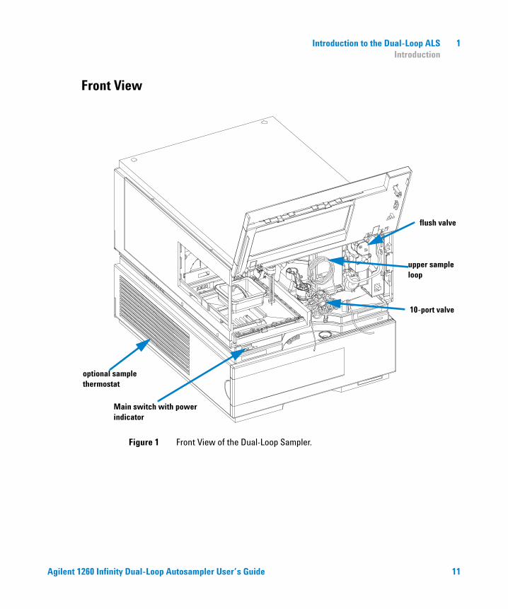
Front View
optional sample thermostat
Main switch with power indicator
10-port valve
flush valve
upper sample loop
Figure 1 Front View of the Dual-Loop Sampler.
Agilent 1260 Infinity Dual-Loop Autosampler User’s Guide 11
1 Introduction to the Dual-Loop ALS Theory of Operation
Theory of Operation
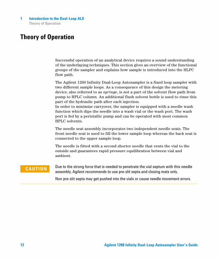
Successful operation of an analytical device requires a sound understanding of the underlaying techniques. This section gives an overview of the functional groups of the sampler and explains how sample is introduced into the HLPC flow path.
The Agilent 1260 Infinity Dual-Loop Autosampler is a fixed loop sampler with two different sample loops. As a consequence of this design the metering device, also referred to as syringe, is not a part of the solvent flow path from pump to HPLC column. An additional flush solvent bottle is used to rinse this part of the hydraulic path after each injection. In order to minimize carryover, the sampler is equipped with a needle wash function which dips the needle into a wash vial or the wash port. The wash port is fed by a peristaltic pump and can be operated with most common HPLC solvents.
The needle seat assembly incorporates two independent needle seats. The front needle seat is used to fill the lower sample loop whereas the back seat is connected to the upper sample loop.
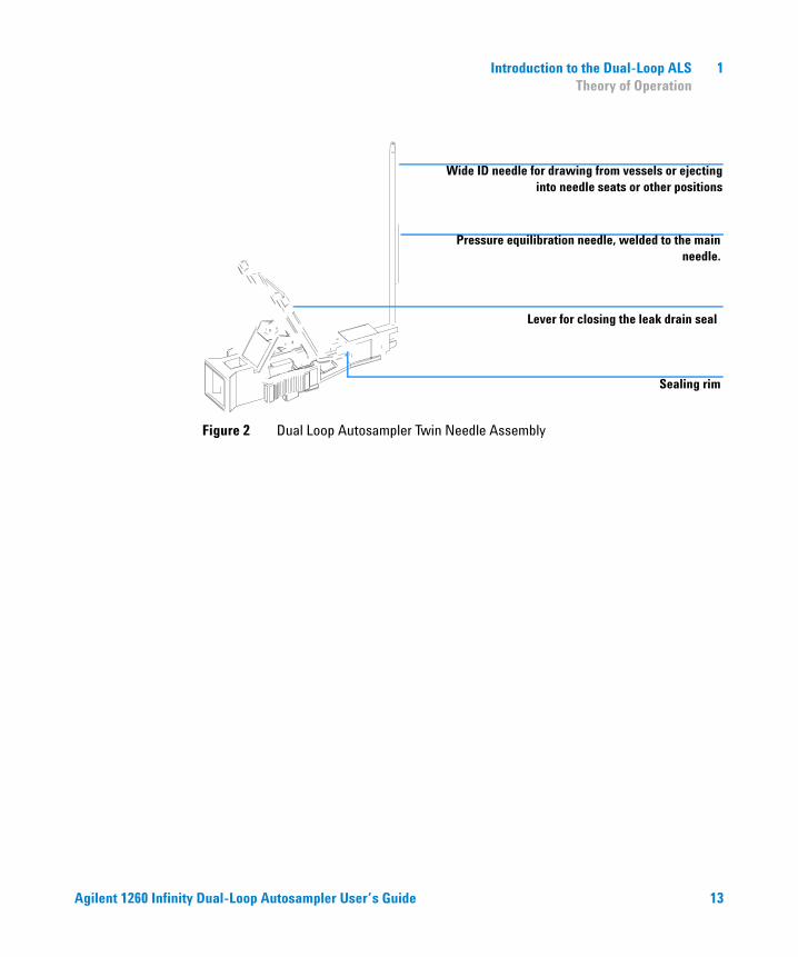
The needle is fitted with a second shorter needle that vents the vial to the outside and guarantees rapid pressure equilibration between vial and ambient.
CAUTION Due to the strong force that is needed to penetrate the vial septum with this needle assembly, Agilent recommends to use pre-slit septa and closing mats only.
Non pre-slit septa may get pushed into the vials or cause needle movement errors.
12 Agilent 1260 Infinity Dual-Loop Autosampler User’s Guide
Introduction to the Dual-Loop ALS 1 Theory of Operation
Figure 2 Dual Loop Autosampler Twin Needle Assembly
Wide ID needle for drawing from vessels or ejecting into needle seats or other positions
Pressure equilibration needle, welded to the main needle.
Lever for closing the leak drain seal
Sealing rim
Agilent 1260 Infinity Dual-Loop Autosampler User’s Guide 13
1 Introduction to the Dual-Loop ALS Theory of Operation
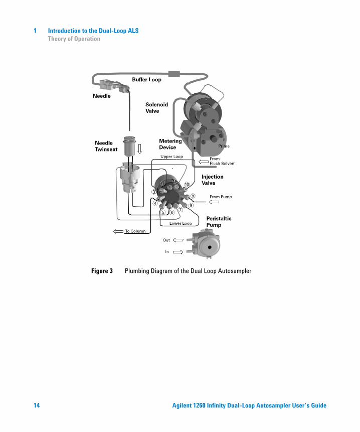
Figure 3 Plumbing Diagram of the Dual Loop Autosampler
14 Agilent 1260 Infinity Dual-Loop Autosampler User’s Guide
Introduction to the Dual-Loop ALS 1 Theory of Operation
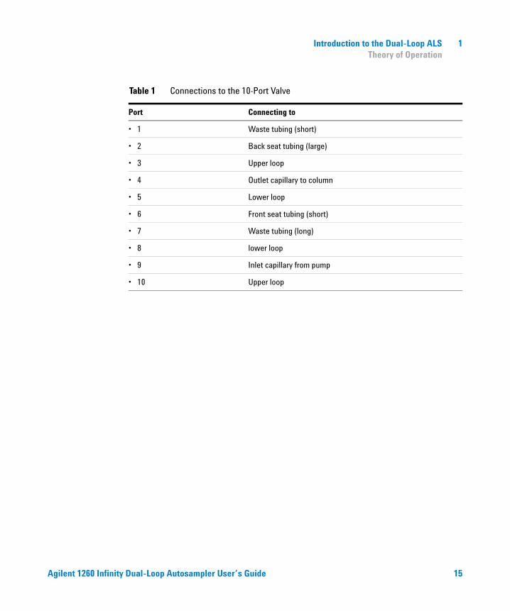
Table 1 Connections to the 10-Port Valve
Port Connecting to
• 1 Waste tubing (short)
• 2 Back seat tubing (large)
• 3 Upper loop
• 4 Outlet capillary to column
• 5 Lower loop
• 6 Front seat tubing (short)
• 7 Waste tubing (long)
• 8 lower loop
• 9 Inlet capillary from pump
• 10 Upper loop
Agilent 1260 Infinity Dual-Loop Autosampler User’s Guide 15
1 Introduction to the Dual-Loop ALS Theory of Operation
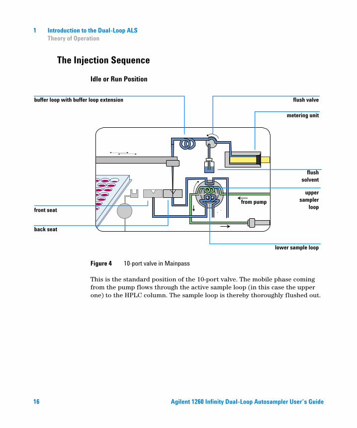
The Injection Sequence
Idle or Run Position
Figure 4 10-port valve in Mainpass
This is the standard position of the 10-port valve. The mobile phase coming from the pump flows through the active sample loop (in this case the upper one) to the HPLC column. The sample loop is thereby thoroughly flushed out.
from pump
buffer loop with buffer loop extension flush valve
metering unit
front seat
back seat
upper sampler
loop
lower sample loop
flush solvent
16 Agilent 1260 Infinity Dual-Loop Autosampler User’s Guide
Introduction to the Dual-Loop ALS 1 Theory of Operation
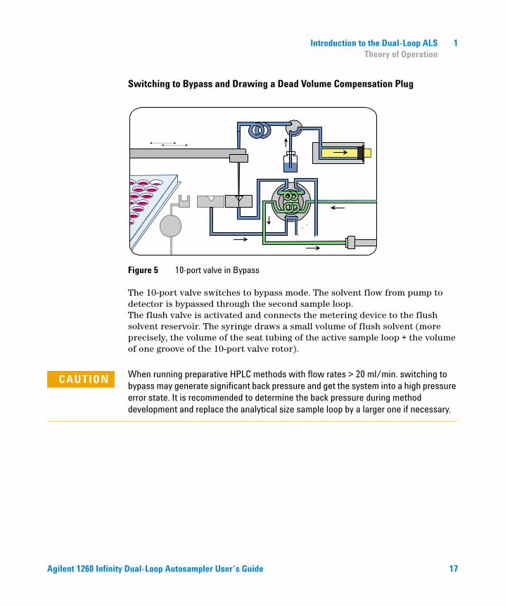
Switching to Bypass and Drawing a Dead Volume Compensation Plug
Figure 5 10-port valve in Bypass
The 10-port valve switches to bypass mode. The solvent flow from pump to detector is bypassed through the second sample loop. The flush valve is activated and connects the metering device to the flush solvent reservoir. The syringe draws a small volume of flush solvent (more precisely, the volume of the seat tubing of the active sample loop + the volume of one groove of the 10-port valve rotor).
CAUTION When running preparative HPLC methods with flow rates > 20 ml/min. switching to bypass may generate significant back pressure and get the system into a high pressure error state. It is recommended to determine the back pressure during method development and replace the analytical size sample loop by a larger one if necessary.
Agilent 1260 Infinity Dual-Loop Autosampler User’s Guide 17
1 Introduction to the Dual-Loop ALS Theory of Operation
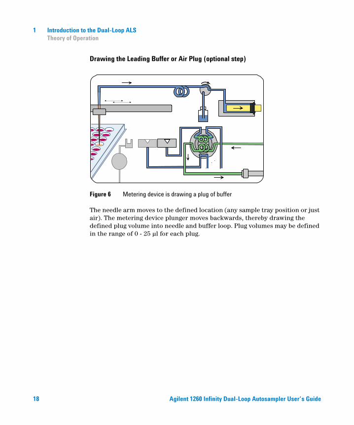
Drawing the Leading Buffer or Air Plug (optional step)
Figure 6 Metering device is drawing a plug of buffer
The needle arm moves to the defined location (any sample tray position or just air). The metering device plunger moves backwards, thereby drawing the defined plug volume into needle and buffer loop. Plug volumes may be defined in the range of 0 - 25 µl for each plug.
18 Agilent 1260 Infinity Dual-Loop Autosampler User’s Guide
Introduction to the Dual-Loop ALS 1 Theory of Operation
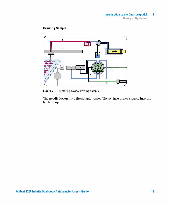
Drawing Sample
Figure 7 Metering device drawing sample
The needle lowers into the sample vessel. The syringe draws sample into the buffer loop.
Agilent 1260 Infinity Dual-Loop Autosampler User’s Guide 19
1 Introduction to the Dual-Loop ALS Theory of Operation
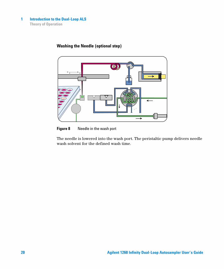
Washing the Needle (optional step)
Figure 8 Needle in the wash port
The needle is lowered into the wash port. The peristaltic pump delivers needle wash solvent for the defined wash time.
20 Agilent 1260 Infinity Dual-Loop Autosampler User’s Guide
Introduction to the Dual-Loop ALS 1 Theory of Operation
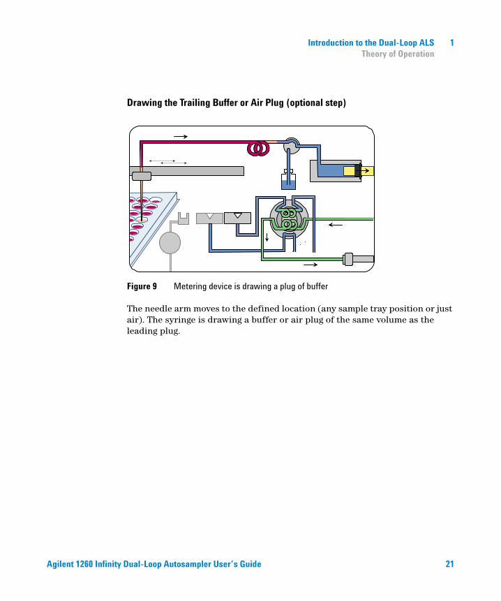
Drawing the Trailing Buffer or Air Plug (optional step)
Figure 9 Metering device is drawing a plug of buffer
The needle arm moves to the defined location (any sample tray position or just air). The syringe is drawing a buffer or air plug of the same volume as the leading plug.
Agilent 1260 Infinity Dual-Loop Autosampler User’s Guide 21
1 Introduction to the Dual-Loop ALS Theory of Operation
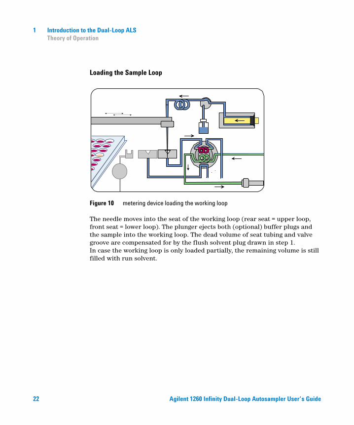
Loading the Sample Loop
Figure 10 metering device loading the working loop
The needle moves into the seat of the working loop (rear seat = upper loop, front seat = lower loop). The plunger ejects both (optional) buffer plugs and the sample into the working loop. The dead volume of seat tubing and valve groove are compensated for by the flush solvent plug drawn in step 1. In case the working loop is only loaded partially, the remaining volume is still filled with run solvent.
22 Agilent 1260 Infinity Dual-Loop Autosampler User’s Guide
Introduction to the Dual-Loop ALS 1 Theory of Operation
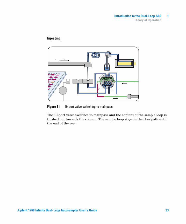
Injecting
Figure 11 10-port valve switching to mainpass
The 10-port valve switches to mainpass and the content of the sample loop is flushed out towards the column. The sample loop stays in the flow path until the end of the run.
Agilent 1260 Infinity Dual-Loop Autosampler User’s Guide 23
1 Introduction to the Dual-Loop ALS Theory of Operation
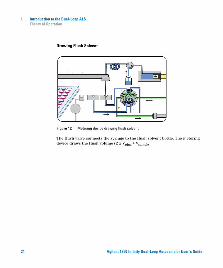
Drawing Flush Solvent
Figure 12 Metering device drawing flush solvent
The flush valve connects the syringe to the flush solvent bottle. The metering device draws the flush volume (2 x Vplug + Vsample).
24 Agilent 1260 Infinity Dual-Loop Autosampler User’s Guide

Introduction to the Dual-Loop ALS 1 Theory of Operation
Washing the Sampling Path
Figure 13 Flushing sampling flow path with flush buffer
Buffer loop, needle, needle seat, seat capillary and valve groove are purged with flush solvent. The last two steps can be repeated multiple times to ensure lowest carryover. 3 - 5 wash cycles are sufficient for most samples.
Agilent 1260 Infinity Dual-Loop Autosampler User’s Guide 25
1 Introduction to the Dual-Loop ALS Theory of Operation
Loop Filling Modes
Fixed loop autosamplers usually purge the loop with sample before switching it into the flow path and flushing the content onto the column. As a consequence, changing the injection volume requires the installation of a loop of different size. Volumes of loops of identical size vary up to 65% depending on loop size and material. The Agilent 1260 Infinity Dual-Loop Autosampler overcomes this limitation with a 10-port valve and two loops of different sizes. Furthermore, it offers different loop filling modes that allow the injection of virtually any desired volume.
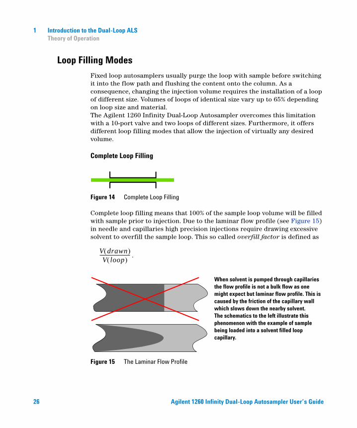
Complete Loop Filling
Figure 14 Complete Loop Filling
V drawn( )V loop( )
-----------------------------
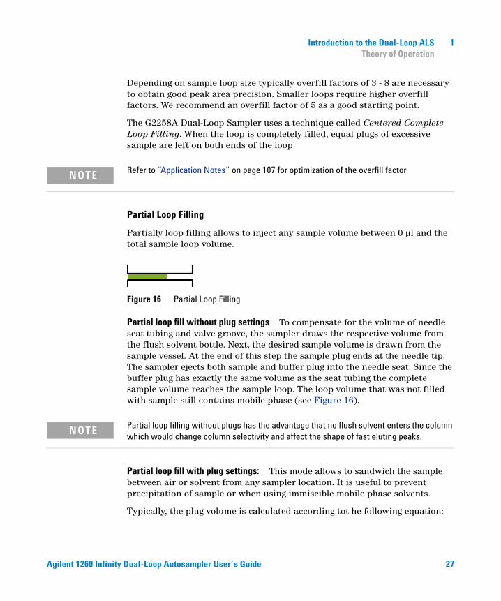
Complete loop filling means that 100% of the sample loop volume will be filled with sample prior to injection. Due to the laminar flow profile (see Figure 15) in needle and capillaries high precision injections require drawing excessive solvent to overfill the sample loop. This so called overfill factor is defined as
.
Figure 15 The Laminar Flow Profile
When solvent is pumped through capillaries the flow profile is not a bulk flow as one might expect but laminar flow profile. This is caused by the friction of the capillary wall which slows down the nearby solvent. The schematics to the left illustrate this phenomenon with the example of sample being loaded into a solvent filled loop capillary.
26 Agilent 1260 Infinity Dual-Loop Autosampler User’s Guide
Introduction to the Dual-Loop ALS 1 Theory of Operation
Refer to “Application Notes” on page 107 for optimization of the overfill factor
Depending on sample loop size typically overfill factors of 3 - 8 are necessary to obtain good peak area precision. Smaller loops require higher overfill factors. We recommend an overfill factor of 5 as a good starting point.
The G2258A Dual-Loop Sampler uses a technique called Centered Complete Loop Filling. When the loop is completely filled, equal plugs of excessive sample are left on both ends of the loop
Partial Loop Filling
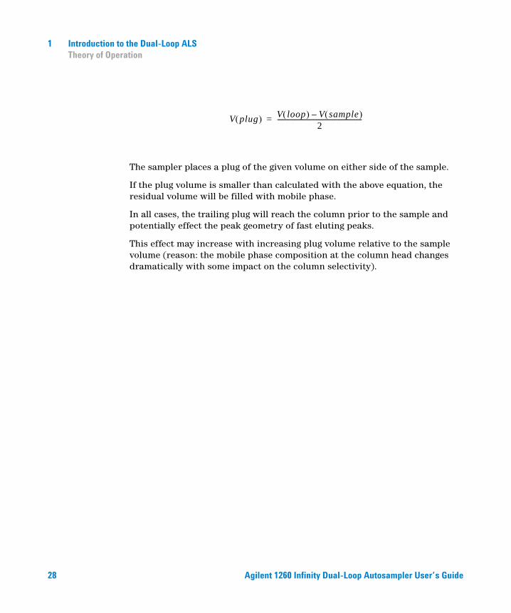
Partially loop filling allows to inject any sample volume between 0 µl and the total sample loop volume.
Figure 16 Partial Loop Filling
Partial loop fill without plug settings
Partial loop filling without plugs has the advantage that no flush solvent enters the column which would change column selectivity and affect the shape of fast eluting peaks.
To compensate for the volume of needle seat tubing and valve groove, the sampler draws the respective volume from the flush solvent bottle. Next, the desired sample volume is drawn from the sample vessel. At the end of this step the sample plug ends at the needle tip. The sampler ejects both sample and buffer plug into the needle seat. Since the buffer plug has exactly the same volume as the seat tubing the complete sample volume reaches the sample loop. The loop volume that was not filled with sample still contains mobile phase (see Figure 16).
Partial loop fill with plug settings: This mode allows to sandwich the sample between air or solvent from any sampler location. It is useful to prevent precipitation of sample or when using immiscible mobile phase solvents.
Typically, the plug volume is calculated according tot he following equation:
NOTE
NOTE
Agilent 1260 Infinity Dual-Loop Autosampler User’s Guide 27
1 Introduction to the Dual-Loop ALS Theory of Operation
The sampler places a plug of the given volume on either side of the sample.
If the plug volume is smaller than calculated with the above equation, the residual volume will be filled with mobile phase.
In all cases, the trailing plug will reach the column prior to the sample and potentially effect the peak geometry of fast eluting peaks.
This effect may increase with increasing plug volume relative to the sample volume (reason: the mobile phase composition at the column head changes dramatically with some impact on the column selectivity).
V plug( ) V loop( ) V sample( )–2
-------------------------------------------------------------=
28 Agilent 1260 Infinity Dual-Loop Autosampler User’s Guide
Agilent 1260 Infinity Dual-Loop AutosamplerUser’s Guide
2Site Requirements and Specifications
Site Requirements 30
Physical Specifications - Dual-Loop Autosampler G2258A 32
Performance Specifications of the Dual-Loop Autosampler 34
Method for Carry-over Test 36
This chapter describes the Site Requirements and Specifications of the Dual Loop Autosampler.
29Agilent Technologies
2 Site Requirements and Specifications Site Requirements
Site Requirements
A suitable site environment is important to ensure optimum performance of the autosampler.
Power Consideration
The autosampler power supply has wide-ranging capability (see Table 1 on page 32). Consequently there is no voltage selector in the rear of the sampler. There are also no externally accessible fuses, because automatic electronic fuses are implemented in the power supply.
The thermostatted autosampler comprises two modules, the sampler (G2258A) and the thermostat (G1330B). Both modules have separate power supplies and power plugs for the line connections. The two modules are connected by a control cable and both are turned on by the sampler module. The thermostat power supply has two externally accessible fuses.
WARNING To disconnect the Dual-Loop Autosampler from line power, unplug the power cord. The power supply still uses some power, even if the power switch on the front panel is turned OFF.
WARNING To disconnect the thermostatted Dual Loop Autosampler from line power, unplug the power cord from the autosampler and the thermostat. The power supplies still use some power, even if the power switch ON the front panel is turned OFF. Please make sure that it is always possible to access the power plug.
WARNING Shock hazard or damage of your instrumentation can result if the devices are connected to a line voltage higher than specified.
30 Agilent 1260 Infinity Dual-Loop Autosampler User’s Guide
Site Requirements and Specifications 2 Site Requirements
Power Cords
Your Dual-Loop Autosampler is delivered with a power cord which matches the wall socket of your particular country or region. The plug on the power cord which connects to the rear of the instrument is identical for all types of power cord.
Bench Space
The Dual-Loop Autosampler dimensions and weight (see Table 1 on page 32) allow the instrument to be placed on almost any laboratory bench. The instrument requires an additional 2.5 cm (1.0 inch) of space on either side, and approximately 8 cm (3.1 inches) at the rear for the circulation of air, and room for electrical connections. Ensure the sampler is installed in a horizontal position.
The thermostatted Dual-Loop Autosampler dimensions and weight (see Table 2 on page 33) allow the instrument to be placed on almost any laboratory bench. The instrument requires an additional 25 cm (10 inches) of space on either side for the circulation of air, and approximately 8 cm (3.1 inches) at the rear for electrical connections. Ensure the sampler is installed in a horizontal position.
If a complete system is to be installed on the bench, make sure that the bench is designed to carry the weight of all the modules. For a complete system including the thermostatted Autosampler it is recommended to position the modules in two stacks, see “Recommended Stack Configuration - Agilent 1260 Infinity Preparative LC System”. Make sure that in this configuration there is 25 cm (10 inches) space on either side of the thermostatted Dual Loop Autosampler for the circulation of air.
WARNING Never operate your instrumentation from a power outlet that has no ground connection. Never use a power cord other than the power cord designed for your region.
WARNING Never use cables other than the ones supplied by Agilent Technologies to ensure proper functionality and compliance with safety or EMC regulations.
Agilent 1260 Infinity Dual-Loop Autosampler User’s Guide 31
2 Site Requirements and Specifications Site Requirements
Environment
Your Dual-Loop Sampler will work within specifications at ambient temperatures and relative humidity as described in Table 1 and Table 2 on page 33.
CAUTION Do not store, ship or use your Dual Loop Autosampler under conditions where temperature fluctuations may cause condensation within the Dual Loop Autosampler. Condensation will damage the system electronics. If your Dual Loop Autosampler was shipped in cold weather, leave it in its box, and allow it to warm up slowly to room temperature to avoid condensation.
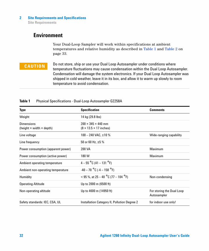
Table 1 Physical Specifications - Dual-Loop Autosampler G2258A
Type Specification Comments
Weight 14 kg (29.8 lbs)
Dimensions (height × width × depth)
200 × 345 × 440 mm (8 × 13.5 × 17 inches)
Line voltage 100 – 240 VAC, ±10 % Wide-ranging capability
Line frequency 50 or 60 Hz, ±5 %
Power consumption (apparent power) 200 VA Maximum
Power consumption (active power) 180 W Maximum
Ambient operating temperature 4 – 55 °C (41 – 131 °F)
Ambient non-operating temperature -40 – 70 °C (-4 – 158 °F)
Humidity < 95 %, at 25 – 40 °C (77 – 104 °F) Non-condensing
Operating Altitude Up to 2000 m (6500 ft)
Non-operating altitude Up to 4600 m (14950 ft) For storing the Dual Loop Autosampler
Safety standards: IEC, CSA, UL Installation Category II, Pollution Degree 2 for indoor use only!
32 Agilent 1260 Infinity Dual-Loop Autosampler User’s Guide
Site Requirements and Specifications 2 Site Requirements
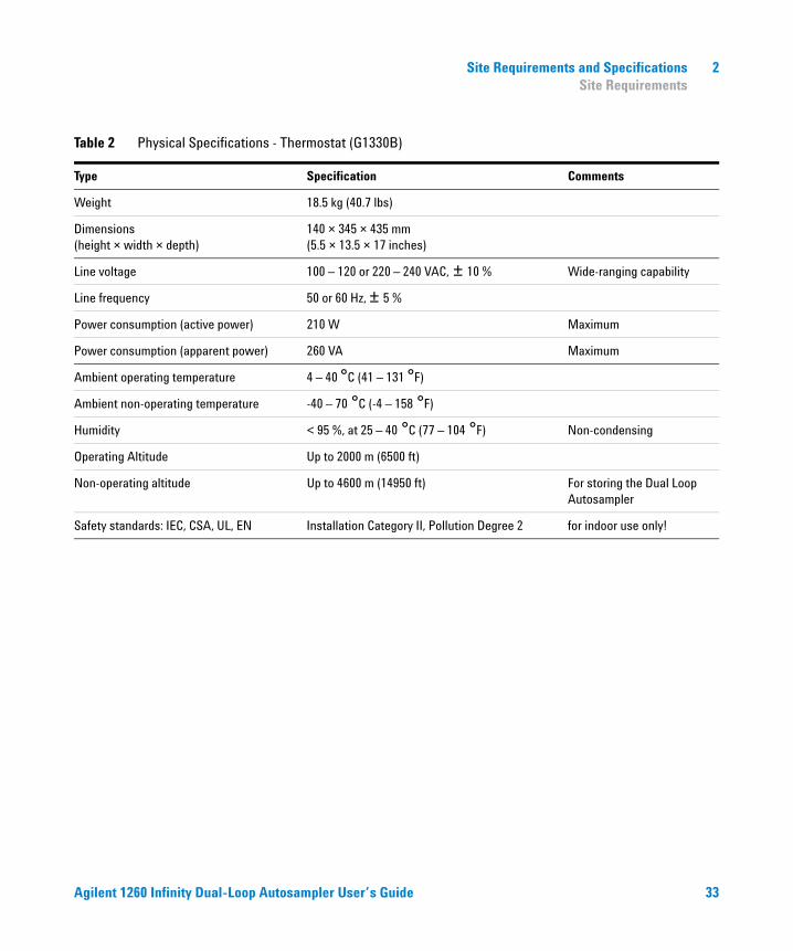
Table 2 Physical Specifications - Thermostat (G1330B)
Type Specification Comments
Weight 18.5 kg (40.7 lbs)
Dimensions (height × width × depth)
140 × 345 × 435 mm (5.5 × 13.5 × 17 inches)
Line voltage 100 – 120 or 220 – 240 VAC, ± 10 % Wide-ranging capability
Line frequency 50 or 60 Hz, ± 5 %
Power consumption (active power) 210 W Maximum
Power consumption (apparent power) 260 VA Maximum
Ambient operating temperature 4 – 40 °C (41 – 131 °F)
Ambient non-operating temperature -40 – 70 °C (-4 – 158 °F)
Humidity < 95 %, at 25 – 40 °C (77 – 104 °F) Non-condensing
Operating Altitude Up to 2000 m (6500 ft)
Non-operating altitude Up to 4600 m (14950 ft) For storing the Dual Loop Autosampler
Safety standards: IEC, CSA, UL, EN Installation Category II, Pollution Degree 2 for indoor use only!
Agilent 1260 Infinity Dual-Loop Autosampler User’s Guide 33
2 Site Requirements and Specifications Performance Specifications of the Dual-Loop Autosampler
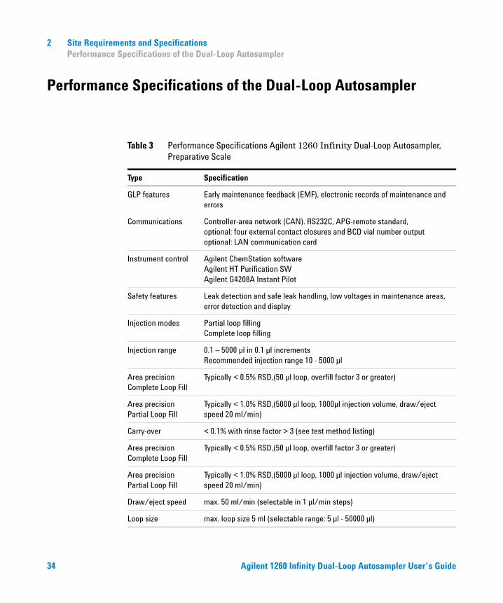
Performance Specifications of the Dual-Loop Autosampler
Table 3 Performance Specifications Agilent 1260 Infinity Dual-Loop Autosampler, Preparative Scale
Type Specification
GLP features Early maintenance feedback (EMF), electronic records of maintenance and errors
Communications Controller-area network (CAN). RS232C, APG-remote standard, optional: four external contact closures and BCD vial number outputoptional: LAN communication card
Instrument control Agilent ChemStation software Agilent HT Purification SWAgilent G4208A Instant Pilot
Safety features Leak detection and safe leak handling, low voltages in maintenance areas, error detection and display
Injection modes Partial loop fillingComplete loop filling
Injection range 0.1 – 5000 µl in 0.1 µl increments Recommended injection range 10 - 5000 µl
Area precision Complete Loop Fill
Typically < 0.5% RSD,(50 µl loop, overfill factor 3 or greater)
Area precision Partial Loop Fill
Typically < 1.0% RSD,(5000 µl loop, 1000µl injection volume, draw/eject speed 20 ml/min)
Carry-over < 0.1% with rinse factor > 3 (see test method listing)
Area precision Complete Loop Fill
Typically < 0.5% RSD,(50 µl loop, overfill factor 3 or greater)
Area precision Partial Loop Fill
Typically < 1.0% RSD,(5000 µl loop, 1000 µl injection volume, draw/eject speed 20 ml/min)
Draw/eject speed max. 50 ml/min (selectable in 1 µl/min steps)
Loop size max. loop size 5 ml (selectable range: 5 µl - 50000 µl)
34 Agilent 1260 Infinity Dual-Loop Autosampler User’s Guide
Site Requirements and Specifications 2 Performance Specifications of the Dual-Loop Autosampler
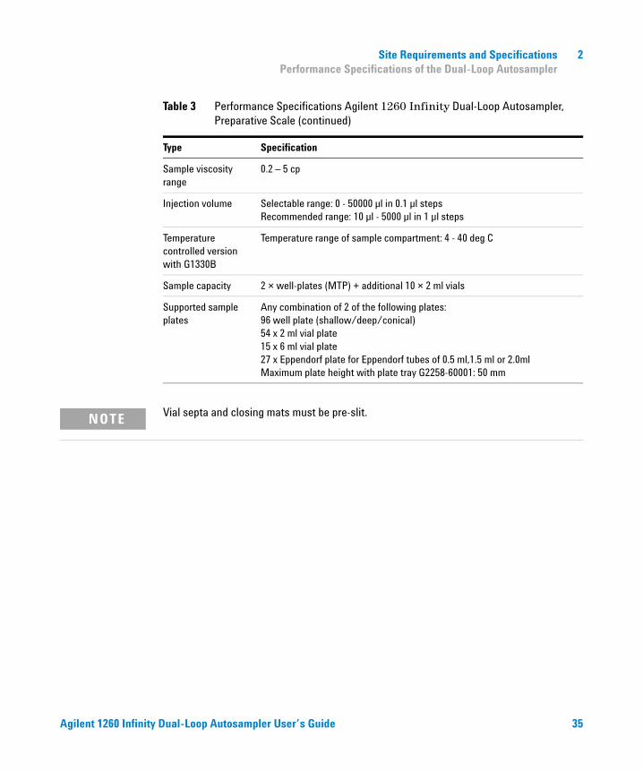
Sample viscosity range
0.2 – 5 cp
Injection volume Selectable range: 0 - 50000 µl in 0.1 µl steps Recommended range: 10 µl - 5000 µl in 1 µl steps
Temperature controlled version with G1330B
Temperature range of sample compartment: 4 - 40 deg C
Sample capacity 2 × well-plates (MTP) + additional 10 × 2 ml vials
Supported sample plates
Any combination of 2 of the following plates:96 well plate (shallow/deep/conical)54 x 2 ml vial plate15 x 6 ml vial plate27 x Eppendorf plate for Eppendorf tubes of 0.5 ml,1.5 ml or 2.0mlMaximum plate height with plate tray G2258-60001: 50 mm
Table 3 Performance Specifications Agilent 1260 Infinity Dual-Loop Autosampler, Preparative Scale (continued)
Type Specification
NOTE Vial septa and closing mats must be pre-slit.
Agilent 1260 Infinity Dual-Loop Autosampler User’s Guide 35
2 Site Requirements and Specifications Performance Specifications of the Dual-Loop Autosampler
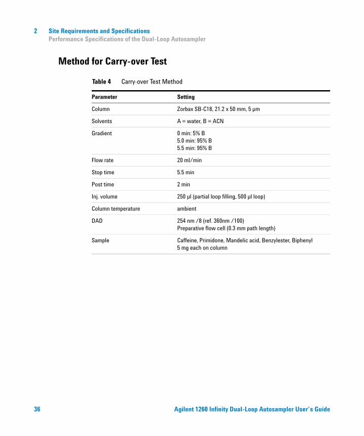
Method for Carry-over Test
Table 4 Carry-over Test Method
Parameter Setting
Column Zorbax SB-C18, 21.2 x 50 mm, 5 µm
Solvents A = water, B = ACN
Gradient 0 min: 5% B5.0 min: 95% B5.5 min: 95% B
Flow rate 20 ml/min
Stop time 5.5 min
Post time 2 min
Inj. volume 250 µl (partial loop filling, 500 µl loop)
Column temperature ambient
DAD 254 nm /8 (ref. 360nm /100)Preparative flow cell (0.3 mm path length)
Sample Caffeine, Primidone, Mandelic acid, Benzylester, Biphenyl 5 mg each on column
36 Agilent 1260 Infinity Dual-Loop Autosampler User’s Guide
Agilent 1260 Infinity Dual-Loop AutosamplerUser’s Guide
3Installing the Dual-Loop Autosampler
Unpacking the Dual-Loop Autosampler 38
Optimizing the Stack Configuration 42
Installation 47
Flushing the Metering Device 58
Configuring Wellplate Types 64
Special Transport Unit Positions 68
This chapter describes the Installation of the Dual Loop Autosampler.
37Agilent Technologies
3 Installing the Dual-Loop Autosampler Unpacking the Dual-Loop Autosampler
Unpacking the Dual-Loop Autosampler
Damaged Packaging
Upon receipt of your autosampler, inspect the shipping containers for any signs of damage. If the containers or cushioning material are damaged, keep them until the contents have been checked for completeness and the Dual Loop Autosampler has been mechanically and electrically checked. If the shipping container or cushioning material are damaged, notify the carrier and keep the shipping material for the carrier‘s inspection.
Delivery Checklist
Ensure all parts and materials have been delivered with the Dual-Loop Autosampler. For this compare the shipment content with the checklist included in each instrument box. Please report missing or damaged parts to your local Agilent Technologies sales and service office.
Two versions of the Agilent 1260 Infinity Dual-Loop Autosampler are available:
• G2258A Dual-Loop Autosampler, preparative scale, designed for flow rates from 1ml/min to 100 ml/min. It can be used with a wide variety of vials and well plates (see “Consumables” on page 122) Fraction Collector.
• G2258A Thermostatted Dual-Loop Autosampler, preparative scale, thermostatisation is achieved by adding a G1330B thermostat.
CAUTION If you need to ship the Dual-Loop Autosampler at a later date, always use the shipping protection foam parts (see “Special Transport Unit Positions” on page 68).
CAUTION If there are signs of damage to the autosampler, please do not attempt to install the module.
38 Agilent 1260 Infinity Dual-Loop Autosampler User’s Guide
Installing the Dual-Loop Autosampler 3 Unpacking the Dual-Loop Autosampler
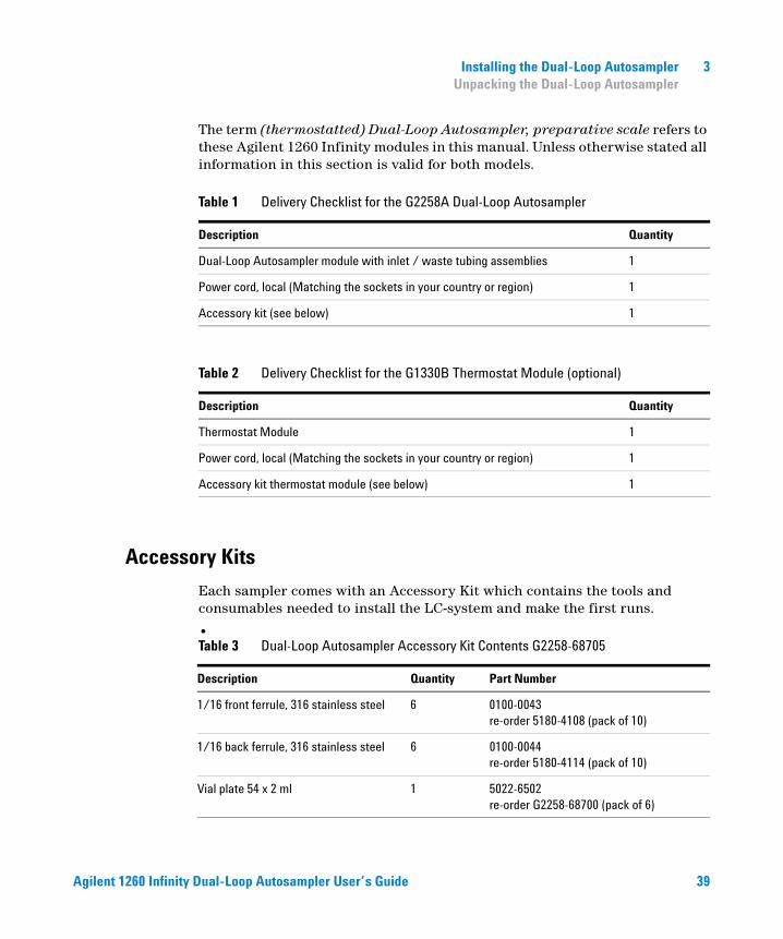
The term (thermostatted) Dual-Loop Autosampler, preparative scale refers to these Agilent 1260 Infinity modules in this manual. Unless otherwise stated all information in this section is valid for both models.
Accessory Kits
Each sampler comes with an Accessory Kit which contains the tools and consumables needed to install the LC-system and make the first runs.
•
Table 1 Delivery Checklist for the G2258A Dual-Loop Autosampler
Description Quantity
Dual-Loop Autosampler module with inlet / waste tubing assemblies 1
Power cord, local (Matching the sockets in your country or region) 1
Accessory kit (see below) 1
Table 2 Delivery Checklist for the G1330B Thermostat Module (optional)
Description Quantity
Thermostat Module 1
Power cord, local (Matching the sockets in your country or region) 1
Accessory kit thermostat module (see below) 1
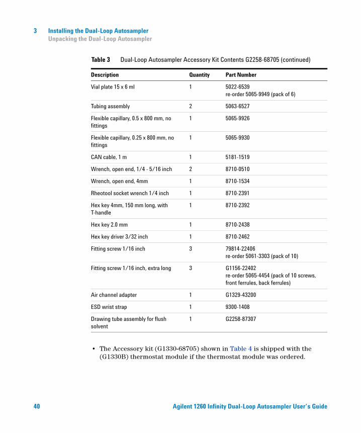
Table 3 Dual-Loop Autosampler Accessory Kit Contents G2258-68705
Description Quantity Part Number
1/16 front ferrule, 316 stainless steel 6 0100-0043 re-order 5180-4108 (pack of 10)
1/16 back ferrule, 316 stainless steel 6 0100-0044 re-order 5180-4114 (pack of 10)
Vial plate 54 x 2 ml 1 5022-6502 re-order G2258-68700 (pack of 6)
Agilent 1260 Infinity Dual-Loop Autosampler User’s Guide 39
3 Installing the Dual-Loop Autosampler Unpacking the Dual-Loop Autosampler
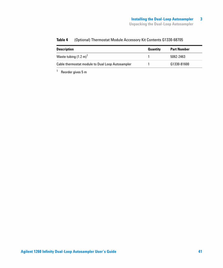
• The Accessory kit (G1330-68705) shown in Table 4 is shipped with the (G1330B) thermostat module if the thermostat module was ordered.
Vial plate 15 x 6 ml 1 5022-6539re-order 5065-9949 (pack of 6)
Tubing assembly 2 5063-6527
Flexible capillary, 0.5 x 800 mm, no fittings
1 5065-9926
Flexible capillary, 0.25 x 800 mm, no fittings
1 5065-9930
CAN cable, 1 m 1 5181-1519
Wrench, open end, 1/4 - 5/16 inch 2 8710-0510
Wrench, open end, 4mm 1 8710-1534
Rheotool socket wrench 1/4 inch 1 8710-2391
Hex key 4mm, 150 mm long, with T-handle
1 8710-2392
Hex key 2.0 mm 1 8710-2438
Hex key driver 3/32 inch 1 8710-2462
Fitting screw 1/16 inch 3 79814-22406 re-order 5061-3303 (pack of 10)
Fitting screw 1/16 inch, extra long 3 G1156-22402 re-order 5065-4454 (pack of 10 screws, front ferrules, back ferrules)
Air channel adapter 1 G1329-43200
ESD wrist strap 1 9300-1408
Drawing tube assembly for flush solvent
1 G2258-87307
Table 3 Dual-Loop Autosampler Accessory Kit Contents G2258-68705 (continued)
Description Quantity Part Number
40 Agilent 1260 Infinity Dual-Loop Autosampler User’s Guide
Installing the Dual-Loop Autosampler 3 Unpacking the Dual-Loop Autosampler
Table 4 (Optional) Thermostat Module Accessory Kit Contents G1330-68705
Description Quantity Part Number
Waste tubing (1.2 m)1
1 Reorder gives 5 m
1 5062-2463
Cable thermostat module to Dual Loop Autosampler 1 G1330-81600
Agilent 1260 Infinity Dual-Loop Autosampler User’s Guide 41
3 Installing the Dual-Loop Autosampler Optimizing the Stack Configuration
Optimizing the Stack Configuration
If your Dual-Loop Autosampler is part of a system, you can ensure optimum performance and minimum delay volume by installing the following configuration.
• Figure 1 and Figure 2 on page 44 show the configuration recommended for the autosampler in an analytical scale system.
• Figure 3 on page 45 and Figure 4 on page 46 show the configuration recommended for the sampler in a preparative scale system.
42 Agilent 1260 Infinity Dual-Loop Autosampler User’s Guide
Installing the Dual-Loop Autosampler 3 Optimizing the Stack Configuration
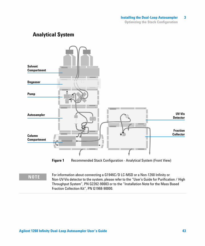
Analytical System
For information about connecting a G1946C/D LC-MSD or a Non-1260 Infinity or Non-UV-Vis detector to the system, please refer to the “User’s Guide for Purification / High Throughput System”, PN G2262-90003 or to the “Installation Note for the Mass Based Fraction Collection Kit”, PN G1968-90000.
Figure 1 Recommended Stack Configuration - Analytical System (Front View)
UV-Vis
FractionCollector
Detector
SolventCompartment
Degasser
Pump
Autosampler
ColumnCompartment
NOTE
Agilent 1260 Infinity Dual-Loop Autosampler User’s Guide 43
3 Installing the Dual-Loop Autosampler Optimizing the Stack Configuration
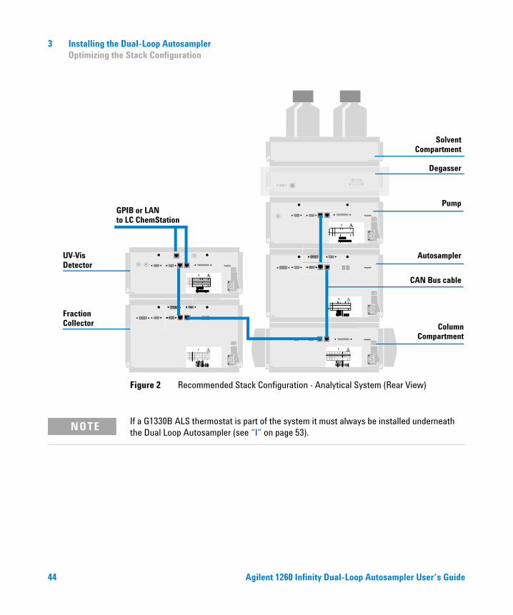
If a G1330B ALS thermostat is part of the system it must always be installed underneath the Dual Loop Autosampler (see “I” on page 53).
Figure 2 Recommended Stack Configuration - Analytical System (Rear View)
SolventCompartment
Degasser
Pump
Autosampler
ColumnCompartment
UV-Vis
FractionCollector
Detector
GPIB or LANto LC ChemStation
CAN Bus cable
NOTE
44 Agilent 1260 Infinity Dual-Loop Autosampler User’s Guide
Installing the Dual-Loop Autosampler 3 Optimizing the Stack Configuration
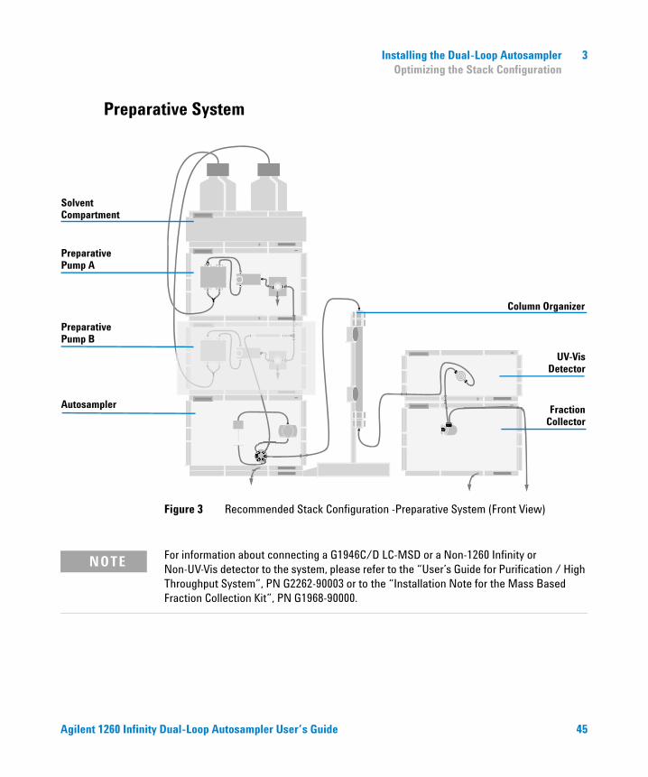
Preparative System
For information about connecting a G1946C/D LC-MSD or a Non-1260 Infinity or Non-UV-Vis detector to the system, please refer to the “User’s Guide for Purification / High Throughput System”, PN G2262-90003 or to the “Installation Note for the Mass Based Fraction Collection Kit”, PN G1968-90000.
Figure 3 Recommended Stack Configuration -Preparative System (Front View)
UV-Vis
FractionCollector
Column Organizer
PreparativePump A
PreparativePump B
SolventCompartment
Autosampler
Detector
NOTE
Agilent 1260 Infinity Dual-Loop Autosampler User’s Guide 45
3 Installing the Dual-Loop Autosampler Optimizing the Stack Configuration
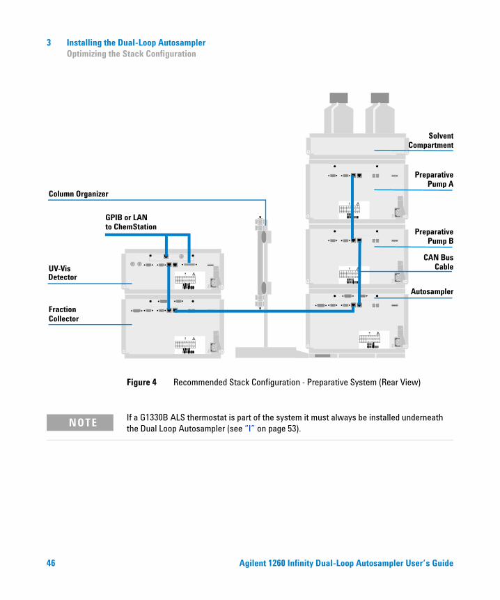
If a G1330B ALS thermostat is part of the system it must always be installed underneath the Dual Loop Autosampler (see “I” on page 53).
Figure 4 Recommended Stack Configuration - Preparative System (Rear View)
UV-Vis
FractionCollector
Detector
PreparativePump A
PreparativePump B
SolventCompartment
Autosampler
Column Organizer
GPIB or LANto ChemStation
CAN BusCable
NOTE
46 Agilent 1260 Infinity Dual-Loop Autosampler User’s Guide
Installing the Dual-Loop Autosampler 3 Installation
Installation
Installing the Dual-Loop Autosampler
1 Install optional BCD or LAN interface boards in Agilent 1260 Infinity detector. For details, see “Firmware Description” in the Service Manual.
2 Remove the adhesive tape which covers the side and front doors.
3 Open the front door and remove the left side door.
4 Remove the transport protection foam.
5 Install two pieces of corrugated waste tubing to the drain ports of the leak plane and the needle wash port.
6 Re-install the left side door (take care of the magnet at the back).
Preparation Locate bench space Provide power connections Unpack the sampler
Parts required Sampler Power cord, for the other cables see below and “Cable Overview” in the Service Manual Chemstation rev. A.10.02 or higher and/or Instant Pilot G4208A.
WARNING To avoid personal injury, keep fingers away from the needle area during Dual Loop Autosampler operation. Do not attempt to insert or remove a vial or a plate when the needle is positioned.
CAUTION Always use the detector as access point for the data system. If another module is used to connect the PC, all data (especially 3D data from the detector) have to be routed via the CAN bus. This may result in reduced system stability. The LAN interface should only be installed if no other option is available.
Agilent 1260 Infinity Dual-Loop Autosampler User’s Guide 47
3 Installing the Dual-Loop Autosampler Installation
7 Place the autosampler in the stack or on the bench in all horizontal position.
8 Ensure the power switch at the front of the sampler is OFF.
9 Connect the power cable to the power connector at the rear of the sampler.
10 Connect the CAN cable to the other Agilent 1260 Infinity modules.
11 If an Agilent ChemStation is the controller, connect the computer to the Agilent 1260 Infinity stack by either LAN connection or GPIB.
12 Connect the APG remote cable (optional) for non Agilent 1260 Infinity instruments.
13 Ensure the side panel is correctly installed.
14 Place the plate tray into the tray base.
15 Turn ON power by pushing the button at the lower left hand side of the sampler.
16 Close the front door. The exhaust fan will turn ON and remove the vapor from the tray compartment. After 1-2 minutes the sampler will start the hardware initialisation process. At the end of this process the status LED should be green.
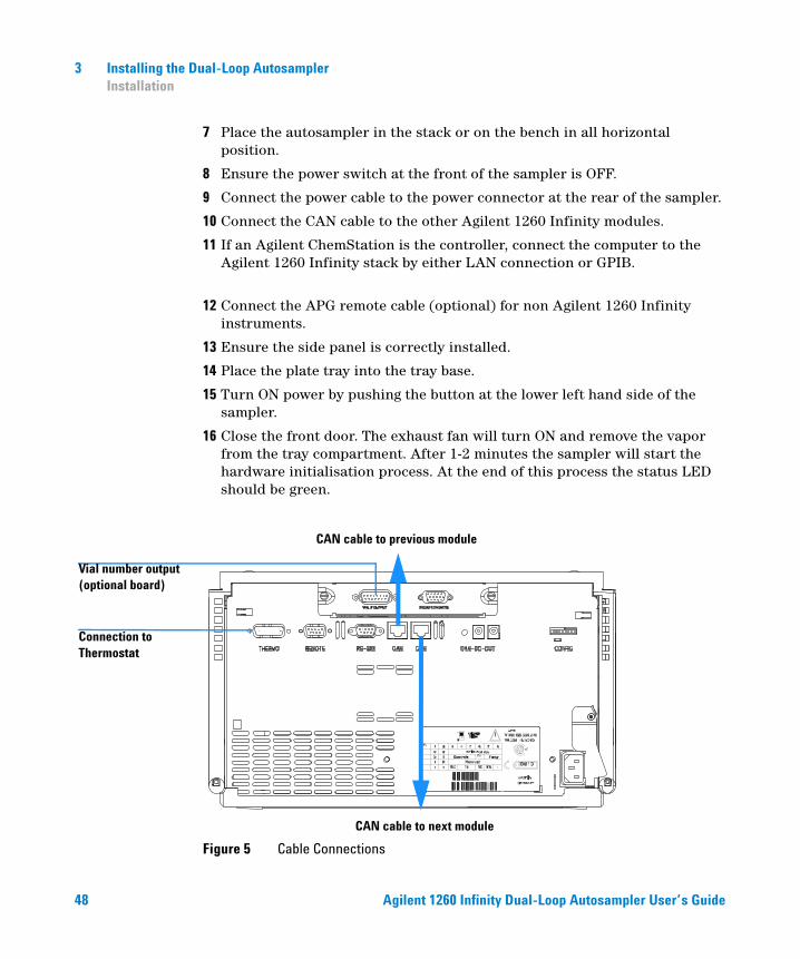
Figure 5 Cable Connections
Vial number output (optional board)
CAN cable to next module
CAN cable to previous module
Connection to Thermostat
48 Agilent 1260 Infinity Dual-Loop Autosampler User’s Guide
Installing the Dual-Loop Autosampler 3 Installation
NOTE The sampler is turned ON when the line power switch is pressed and the green indicator lamp is illuminated. The sampler is turned OFF when the line power switch is protruding and the green light is OFF.
WARNING To disconnect the sampler from the line, unplug the power cord. The power will supply still uses some power, even switch at the front panel is turned OFF.
Agilent 1260 Infinity Dual-Loop Autosampler User’s Guide 49
3 Installing the Dual-Loop Autosampler Installation
Installing a Thermostatted Dual-Loop Autosampler
1 Place the thermostat onto the bench.
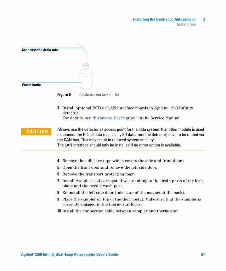
2 Remove the front cover and route the condensation drain tube to the waste bottle.
Preparation Locate bench space Provide power connections Unpack the sampler and the thermostat
Parts required Sampler and thermostat Power cord, for the other cables see below and Cable Overview in the Service ManualChemStation and/or Instant Pilot G4208A.
WARNING Make sure that the condensation drain tube is always above the liquid level in the vessel. If the tube is located in liquid the condensed water cannot flow out of the tube and the outlet is blocked. Any further condensation will then remain in the instrument. This may damage the instruments electronics.
50 Agilent 1260 Infinity Dual-Loop Autosampler User’s Guide
Installing the Dual-Loop Autosampler 3 Installation
3 Install optional BCD or LAN interface boards in Agilent 1260 Infinity detector. For details, see “Firmware Description” in the Service Manual.
4 Remove the adhesive tape which covers the side and front doors.
5 Open the front door and remove the left side door.
6 Remove the transport protection foam.
7 Install two pieces of corrugated waste tubing to the drain ports of the leak plane and the needle wash port.
8 Re-install the left side door (take care of the magnet at the back).
9 Place the sampler on top of the thermostat. Make sure that the sampler is correctly engaged in the thermostat locks.
10 Install the connection cable between sampler and thermostat
Figure 6 Condensation leak outlet
Condensation drain tube
Waste bottle
CAUTION Always use the detector as access point for the data system. If another module is used to connect the PC, all data (especially 3D data from the detector) have to be routed via the CAN bus. This may result in reduced system stability. The LAN interface should only be installed if no other option is available.
Agilent 1260 Infinity Dual-Loop Autosampler User’s Guide 51
3 Installing the Dual-Loop Autosampler Installation
Install the connection cable between sampler and thermostat.
11 Remove the tray and the plastic cover from the tray base, place the air channel adapter into the sampler tray base. Make sure the adapter is fully seated.
12 Place the plate tray into the tray base.
13 Turn ON power by pushing the button at the lower left hand side of the Dual Loop Autosampler.
14 The exhaust fan will turn ON and remove potential solvent vapor from the inside of the instrument. After 2 minutes close the front door. Then the Dual Loop Autosampler will start the hardware initialization process. At the end of this process the status LED should be green.
WARNING Do not disconnect or reconnect the Dual Loop Autosampler to thermostat cable when the power cords are connected to either of the two modules. This will damage the electronics of the modules.
52 Agilent 1260 Infinity Dual-Loop Autosampler User’s Guide
Installing the Dual-Loop Autosampler 3 Installation
The Dual Loop Autosampler is turned ON when the line power switch is pressed and the green indicator lamp is illuminated. The detector is turned OFF when the line power switch is protruding and the green light is OFF.
I
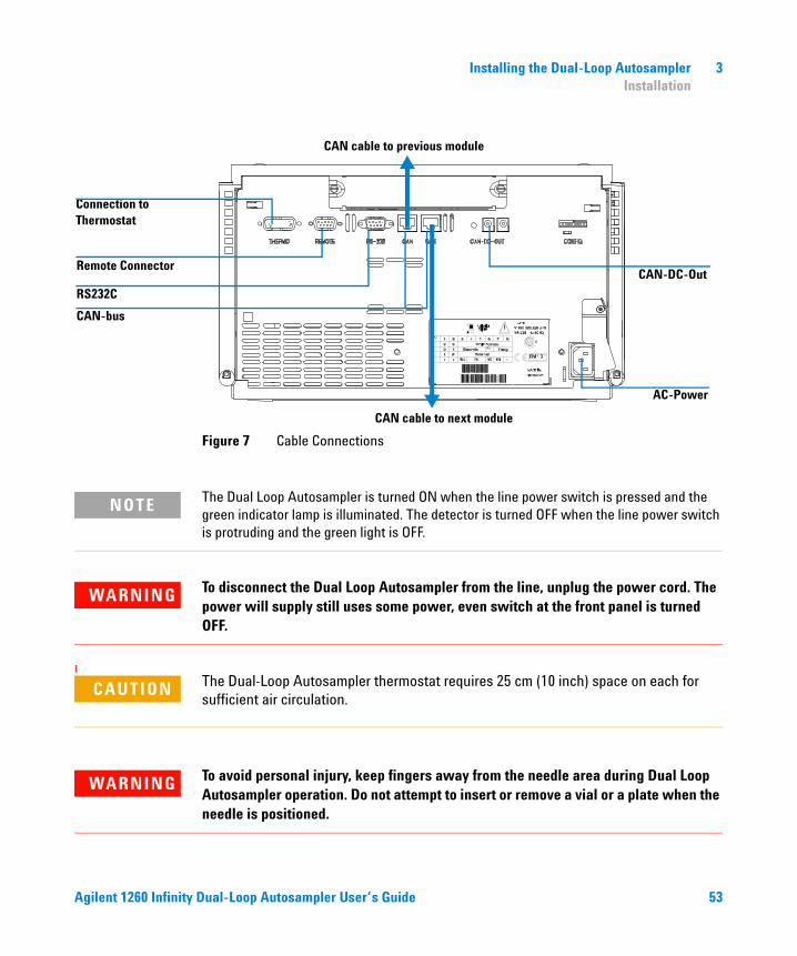
Figure 7 Cable Connections
RS232C
CAN-bus
Remote Connector
CAN cable to next module
CAN cable to previous module
Connection to Thermostat
CAN-DC-Out
AC-Power
NOTE
WARNING To disconnect the Dual Loop Autosampler from the line, unplug the power cord. The power will supply still uses some power, even switch at the front panel is turned OFF.
CAUTION The Dual-Loop Autosampler thermostat requires 25 cm (10 inch) space on each for sufficient air circulation.
WARNING To avoid personal injury, keep fingers away from the needle area during Dual Loop Autosampler operation. Do not attempt to insert or remove a vial or a plate when the needle is positioned.
Agilent 1260 Infinity Dual-Loop Autosampler User’s Guide 53
3 Installing the Dual-Loop Autosampler Installation
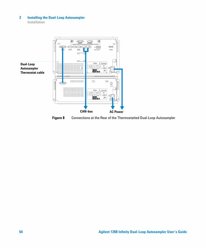
Figure 8 Connections at the Rear of the Thermostatted Dual-Loop Autosampler
Dual-Loop Autosampler Thermostat cable
CAN-bus AC Power
54 Agilent 1260 Infinity Dual-Loop Autosampler User’s Guide
Installing the Dual-Loop Autosampler 3 Installation
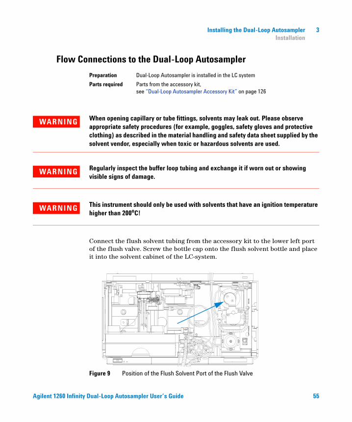
Flow Connections to the Dual-Loop Autosampler
Connect the flush solvent tubing from the accessory kit to the lower left port of the flush valve. Screw the bottle cap onto the flush solvent bottle and place it into the solvent cabinet of the LC-system.
Preparation Dual-Loop Autosampler is installed in the LC system
Parts required Parts from the accessory kit, see “Dual-Loop Autosampler Accessory Kit” on page 126
WARNING When opening capillary or tube fittings, solvents may leak out. Please observe appropriate safety procedures (for example, goggles, safety gloves and protective clothing) as described in the material handling and safety data sheet supplied by the solvent vendor, especially when toxic or hazardous solvents are used.
WARNING Regularly inspect the buffer loop tubing and exchange it if worn out or showing visible signs of damage.
WARNING This instrument should only be used with solvents that have an ignition temperature higher than 200oC!
Figure 9 Position of the Flush Solvent Port of the Flush Valve
Agilent 1260 Infinity Dual-Loop Autosampler User’s Guide 55
3 Installing the Dual-Loop Autosampler Installation
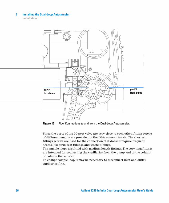
Since the ports of the 10-port valve are very close to each other, fitting screws of different lengths are provided in the DLA accessories kit. The shortest fittings screws are used for the connection that doesn’t require frequent access, like twin seat tubings and waste tubings. The sample loops are fitted with medium length fittings. The very long fittings are intended for connecting the capillaries from the pump and to the column or column thermostat. To change sample loop it may be necessary to disconnect inlet and outlet capillaries first.
Figure 10 Flow Connections to and from the Dual-Loop Autosampler.
port 4 to column
port 9 from pump
56 Agilent 1260 Infinity Dual-Loop Autosampler User’s Guide
Installing the Dual-Loop Autosampler 3 Installation
1 String a back ferrule, a front ferrule and long fitting screw onto the orange 0.5 x 800 mm capillary from the accessories kit.
2 Put the end of the capillary completely into port 9 of the 10-port valve.
3 Tighten the fitting screw while pushing the tubing in to the valve port.
4 When finger-tight, use a 1/4 inch wrench or the RheoTool to tighten the screw another 1/2 to 3/4 turn to seal the fitting pressure tight.
5 Repeat steps 1 to 4 with the other end of the capillary but use the pump outlet fitting for swaging. Use one of the shorter fitting screws. This procedure ensures that dead volumes are avoided, no matter what pump is used.
6 String a back ferrule, a front ferrule and long fitting screw onto the blue 0.25 x 800 mm capillary from the accessories kit.
7 Put the end of the capillary completely into port 4 of the 10-port valve.
8 Tighten the fitting screw while pushing the tubing in to the valve port.
9 When finger-tight, use a 1/4 inch wrench or the RheoTool to tighten the screw another 1/2 to 3/4 turn to seal the fitting pressure tight.
10 Swage the other end of the blue capillary to the fitting of your column accordingly. Use one of the shorter fitting screws.
CAUTION After replacing sample loops or capillaries on the 10-port valve, check if all other connections are still tight. Due to the very tight space it may happen the an adjacent fitting gets loose.
Agilent 1260 Infinity Dual-Loop Autosampler User’s Guide 57
3 Installing the Dual-Loop Autosampler Flushing the Metering Device
Flushing the Metering Device
Initial Priming by Backflushing with External Pump
Air in the metering device results in unpredictable injection volumes and large peak area standard deviation. It is essential to remove any gas from the metering head, the solenoid valve and all tubing before an analysis is started. The following procedures explain for this is achieved effectively.
Steps 1 - 7 are only necessary if metering head and tubings are completely dry (e.g. during installation or after replacing metering seal or piston)
1 Fill the flush solvent bottle of the Dual-Loop Sampler with 250 ml Isopropanol
2 Remove the blue purge plug from the metering head assembly. Connect the pump of the LC system (e.g. G1310B, G1311B/C, G1312B/C or G1361A) with a 0.5 mm ID capillary to this purge port.
3 Put the solvent intake tubing of the pump into a vessel with Isopropanol. Turn the pump on and start flushing at 5 ml/min until the solvent drains from on of the 10-port valve waste tubings.
4 Accelerate the pump to 10 ml/min (max.) for another 3 – 5 min
5 Switch OFF the pump flow.
6 Disconnect the capillary and close the purge port with the blue plug.
7 Place the flush solvent bottle into your solvent cabinet.
When required At initial installation or if the metering head is filled with air (e.g. after replacing seal or piston)
Tools required 1/4 inch-5/16 inch wrench 8710-0510 (supplied in accessory kit)
Parts required none
58 Agilent 1260 Infinity Dual-Loop Autosampler User’s Guide
Installing the Dual-Loop Autosampler 3 Flushing the Metering Device
Purging the Syringe
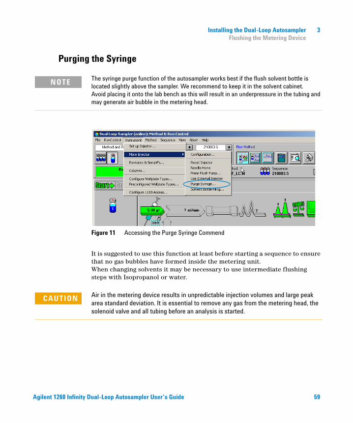
The syringe purge function of the autosampler works best if the flush solvent bottle is located slightly above the sampler. We recommend to keep it in the solvent cabinet. Avoid placing it onto the lab bench as this will result in an underpressure in the tubing and may generate air bubble in the metering head.
It is suggested to use this function at least before starting a sequence to ensure that no gas bubbles have formed inside the metering unit. When changing solvents it may be necessary to use intermediate flushing steps with Isopropanol or water.
NOTE
Figure 11 Accessing the Purge Syringe Commend
CAUTION Air in the metering device results in unpredictable injection volumes and large peak area standard deviation. It is essential to remove any gas from the metering head, the solenoid valve and all tubing before an analysis is started.
Agilent 1260 Infinity Dual-Loop Autosampler User’s Guide 59
3 Installing the Dual-Loop Autosampler Flushing the Metering Device
1 Start purging the sampler from the Instrument menu of Agilent ChemStation (see Figure 11) or from Views > System > DL Sampler > Purge > Syringe on the handheld controller until the flush solvent has reached the inlet tubing to the metering head.
2 Continue purging for another 5 to 10 times to ensure that metering head is free of gas bubbles.
3 If applicable: Change the solvent as needed and flush 10 times with new solvent.
Flushing the Syringe
Reasons to flush the Syringe
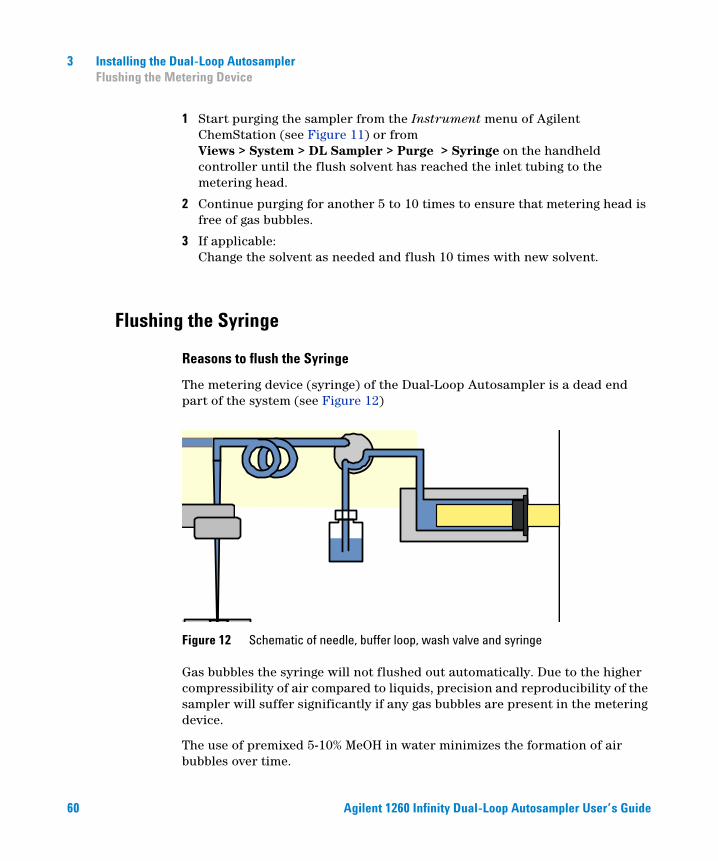
The metering device (syringe) of the Dual-Loop Autosampler is a dead end part of the system (see Figure 12)
Figure 12 Schematic of needle, buffer loop, wash valve and syringe
Gas bubbles the syringe will not flushed out automatically. Due to the higher compressibility of air compared to liquids, precision and reproducibility of the sampler will suffer significantly if any gas bubbles are present in the metering device.
The use of premixed 5-10% MeOH in water minimizes the formation of air bubbles over time.
60 Agilent 1260 Infinity Dual-Loop Autosampler User’s Guide
Installing the Dual-Loop Autosampler 3 Flushing the Metering Device
• In order to keep sample contamination low, you will have to rinse the syringe loop prior to next injection. (This is not necessary for repetitive injections).
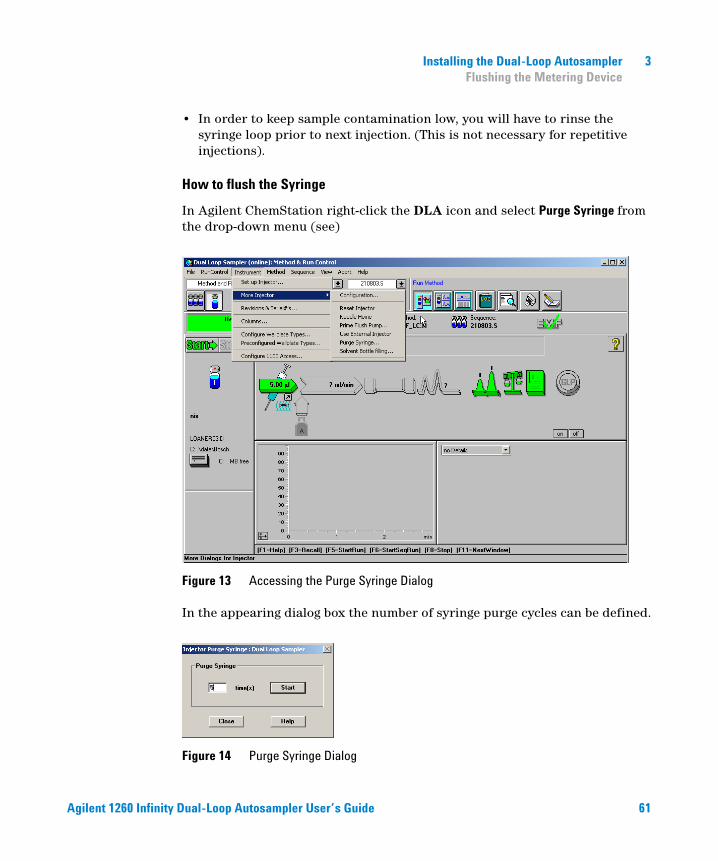
How to flush the Syringe
In Agilent ChemStation right-click the DLA icon and select Purge Syringe from the drop-down menu (see)
Figure 13 Accessing the Purge Syringe Dialog
In the appearing dialog box the number of syringe purge cycles can be defined.
Figure 14 Purge Syringe Dialog
Agilent 1260 Infinity Dual-Loop Autosampler User’s Guide 61
3 Installing the Dual-Loop Autosampler Flushing the Metering Device
This command is interactive. Add how often you wish to purge the syringe and press Start.
In the example above, the syringe will draw and eject five times its total volume of 5 ml flush solvent at the maximum speed of 50 ml/min. The flush solvent is ejected directly into waste. (The waste position is in front of the needle wash port).
How much Flush Solvent is needed?
Whenever changing the flush solvent to a solvent with different properties, flush your syringe about 5 – 10 times, depending on the viscosity and the volume of the inlet tube, to be sure that the old solvent has been replaced quantitatively.
Additional Information
Store your flush solvent in the solvent cabinet on top of the Agilent 1260 Infinity system. The metering device can draw solvent only from the same height as the metering device itself or higher.
Always use the inlet solvent filter and clean or replace it from time to time in order to protect your metering device.
Similar to the Bottle Filling function of the Agilent HPLC pumps, the Dual-Loop Autosampler tracks the flush solvent level and stops the system before running out of solvent. In ChemStation the function is accessed from the Method & Run Control screen by pulling down the Instrument menu clicking Solvent Bottle Filling.
CAUTION Use Propanol-2 as an intermediary for not completely miscible solvents.
62 Agilent 1260 Infinity Dual-Loop Autosampler User’s Guide
Installing the Dual-Loop Autosampler 3 Flushing the Metering Device
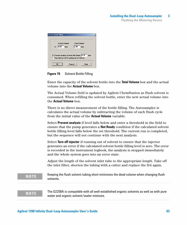
Figure 15 Solvent Bottle Filling
Keeping the flush solvent tubing short minimizes the dead volume when changing flush solvents.
The G2258A is compatible with all well-established organic solvents as well as with pure water and organic solvent/water mixtures.
Enter the capacity of the solvent bottle into the Total Volume box and the actual volume into the Actual Volume box.
The Actual Volume field is updated by Agilent ChemStation as flush solvent is consumed. When refilling the solvent bottle, enter the new actual volume into the Actual Volume box.
There is no direct measurement of the bottle filling. The Autosampler is calculates the actual volume by subtracting the volume of each flush cycle from the initial value of the Actual Volume variable.
Select Prevent analysis if level falls below and enter a threshold in the field to ensure that the pump generates a Not Ready condition if the calculated solvent bottle filling level falls below the set threshold. The current run is completed, but the sequence will not continue with the next analysis.
Select Turn off injector if running out of solvent to ensure that the injector generates an error if the calculated solvent bottle filling level is zero. The error is recorded in the instrument logbook, the analysis is stopped immediately and the whole system goes into an error state.
Adjust the length of the solvent inlet tube to the appropriate length. Take off the inlet filter, shorten the tubing with a cutter and replace the frit again.
NOTE
NOTE
Agilent 1260 Infinity Dual-Loop Autosampler User’s Guide 63
3 Installing the Dual-Loop Autosampler Configuring Wellplate Types
Configuring Wellplate Types
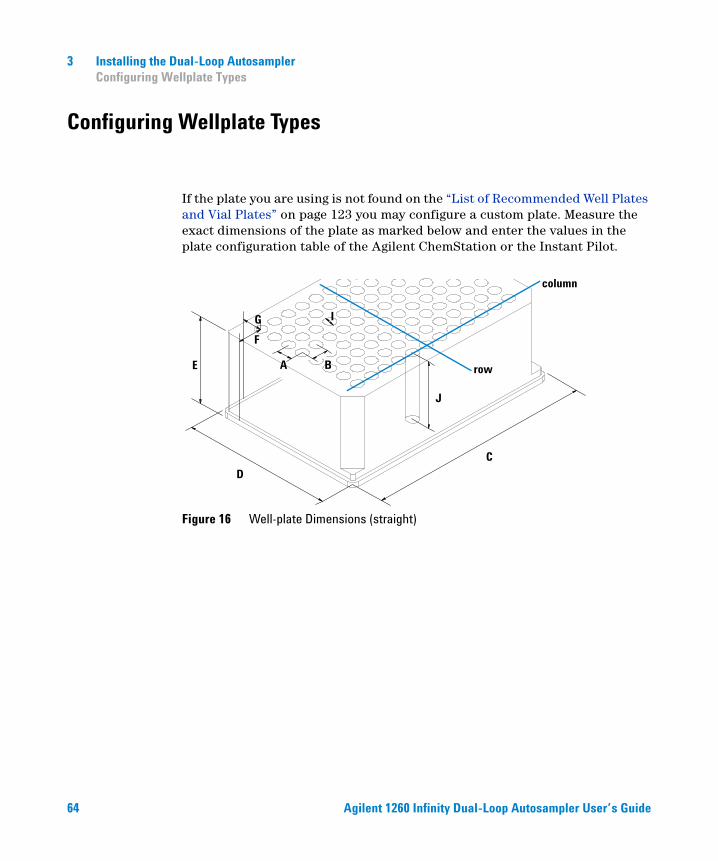
If the plate you are using is not found on the “List of Recommended Well Plates and Vial Plates” on page 123 you may configure a custom plate. Measure the exact dimensions of the plate as marked below and enter the values in the plate configuration table of the Agilent ChemStation or the Instant Pilot.
Figure 16 Well-plate Dimensions (straight)
F
B
C
D
E A
G I
J
column
row
64 Agilent 1260 Infinity Dual-Loop Autosampler User’s Guide
Installing the Dual-Loop Autosampler 3 Configuring Wellplate Types
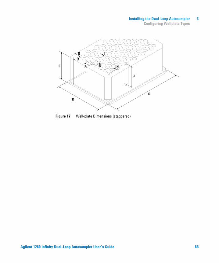
Figure 17 Well-plate Dimensions (staggered)
F
B
C
D
E A
G I
J
H
Agilent 1260 Infinity Dual-Loop Autosampler User’s Guide 65
3 Installing the Dual-Loop Autosampler Configuring Wellplate Types
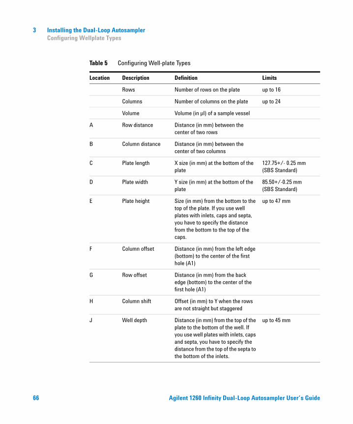
Table 5 Configuring Well-plate Types
Location Description Definition Limits
Rows Number of rows on the plate up to 16
Columns Number of columns on the plate up to 24
Volume Volume (in µI) of a sample vessel
A Row distance Distance (in mm) between the center of two rows
B Column distance Distance (in mm) between the center of two columns
C Plate length X size (in mm) at the bottom of the plate
127.75+/- 0.25 mm (SBS Standard)
D Plate width Y size (in mm) at the bottom of the plate
85.50+/-0.25 mm (SBS Standard)
E Plate height Size (in mm) from the bottom to the top of the plate. If you use well plates with inlets, caps and septa, you have to specify the distance from the bottom to the top of the caps.
up to 47 mm
F Column offset Distance (in mm) from the left edge (bottom) to the center of the first hole (A1)
G Row offset Distance (in mm) from the back edge (bottom) to the center of the first hole (A1)
H Column shift Offset (in mm) to Y when the rows are not straight but staggered
J WeIl depth Distance (in mm) from the top of the plate to the bottom of the well. If you use well plates with inlets, caps and septa, you have to specify the distance from the top of the septa to the bottom of the inlets.
up to 45 mm
66 Agilent 1260 Infinity Dual-Loop Autosampler User’s Guide
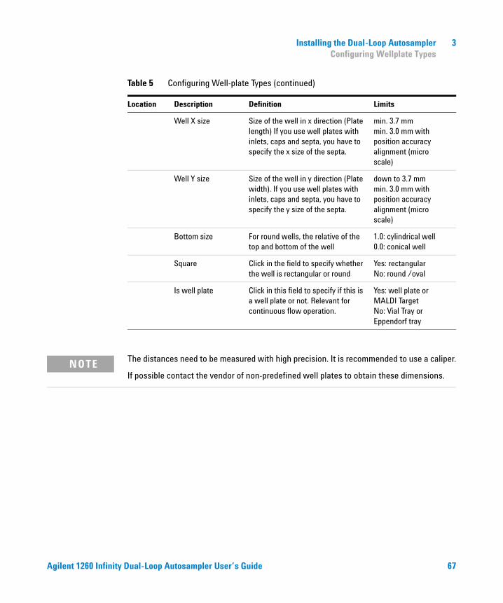
Installing the Dual-Loop Autosampler 3 Configuring Wellplate Types
The distances need to be measured with high precision. It is recommended to use a caliper.
If possible contact the vendor of non-predefined well plates to obtain these dimensions.
Well X size Size of the well in x direction (Plate length) If you use well plates with inlets, caps and septa, you have to specify the x size of the septa.
min. 3.7 mm min. 3.0 mm with position accuracy alignment (micro scale)
Well Y size Size of the well in y direction (Plate width). If you use well plates with inlets, caps and septa, you have to specify the y size of the septa.
down to 3.7 mm min. 3.0 mm with position accuracy alignment (micro scale)
Bottom size For round wells, the relative of the top and bottom of the well
1.0: cylindrical well 0.0: conical well
Square Click in the field to specify whether the well is rectangular or round
Yes: rectangularNo: round /oval
Is well plate Click in this field to specify if this is a well plate or not. Relevant for continuous flow operation.
Yes: well plate or MALDI Target No: Vial Tray or Eppendorf tray
Table 5 Configuring Well-plate Types (continued)
Location Description Definition Limits
NOTE
Agilent 1260 Infinity Dual-Loop Autosampler User’s Guide 67
3 Installing the Dual-Loop Autosampler Special Transport Unit Positions
Special Transport Unit Positions
Transporting the Dual-Loop Autosampler
When moving the Dual Loop Autosampler inside the laboratory, no special precautions are needed. However, if the Dual Loop Autosampler needs to be shipped to another location via carrier, ensure:
✔ The transport assembly is in the park position. Use the Agilent ChemStation or the Instant Pilot for this command.
To move the arm to the park position:
1 Switch to the Diagnosis view of the Agilent ChemStation and select Dual Loop ALS > Maintenance Positions from the Maintenance menu.
2 In the upcoming dialog box click the Park Arm button.
✔ The vial tray and the sample transport mechanism is secured with the transport protection foam.
Maintenance Positions
Maintenance and repairs require to move certain assemblies of the Dual-Loop Autosampler into dedicated maintenance positions.
Access to the maintenance positions
Chemstation Diagnosis View - Maintenance - Dual Loop ALS - Maintenance Positions
68 Agilent 1260 Infinity Dual-Loop Autosampler User’s Guide
Agilent 1260 Infinity Dual-Loop AutosamplerUser’s Guide
4Using the Dual-Loop Autosampler
General Comments about Sample Trays 70
Supported Trays 70
Unsupported Trays 70
Operating the Dual-Loop Sampler with Agilent ChemStation 71
Operating the Dual-Loop Sampler with Agilent ChemStation 71
Navigation in Agilent ChemStation 71
Achieving the Best Recovery Results with the Agilent 1260 Infinity Dual-Loop Autosampler PS 81
This chapter describes the Usage of the Dual Loop Autosampler.
69Agilent Technologies
4 Using the Dual-Loop Autosampler General Comments about Sample Trays
General Comments about Sample Trays
Supported Trays
The Dual-Loop Autosampler recognizes the installed tray automatically. Two supported trays are available:
Standard 2 well plate tray, PN G1367-60001 This tray can hold up to two well plates or vial plates. The maximum vessel height is 48mm.
Well plate tray, 2 well plates, 10 vials (supports 50 mm plates), PN G2258-60001
This new tray can hold up to two well plates or vial plates. The sample plates are positioned two millimeters lower than in the standard sample tray. This allows the use of vessels with a maximum height of 50mm
Unsupported Trays
The following vial trays are not supported with the G2258A Dual-Loop Autosampler:
• Std. tray for 100 x 2ml vials, PN G1313-44500
• Std. tray for 100 x 2ml vials, thermostat able, PN G1329-60001
• Half tray for 40 x 2ml vials, PN G1313-44502
• Half tray for 15 x 6ml vials, PN G1313-44503
These trays have larger bore holes for the vial which spoil the positioning accuracy of the Dual-Loop Autosampler
CAUTION Other trays are not supported with the Dual-Loop Autosampler because their use may cause damages to the needle under special circumstances. These damages are not covered by instrument warranty.
70 Agilent 1260 Infinity Dual-Loop Autosampler User’s Guide
Using the Dual-Loop Autosampler 4 Operating the Dual-Loop Sampler with Agilent ChemStation
Operating the Dual-Loop Sampler with Agilent ChemStation
Navigation in Agilent ChemStation
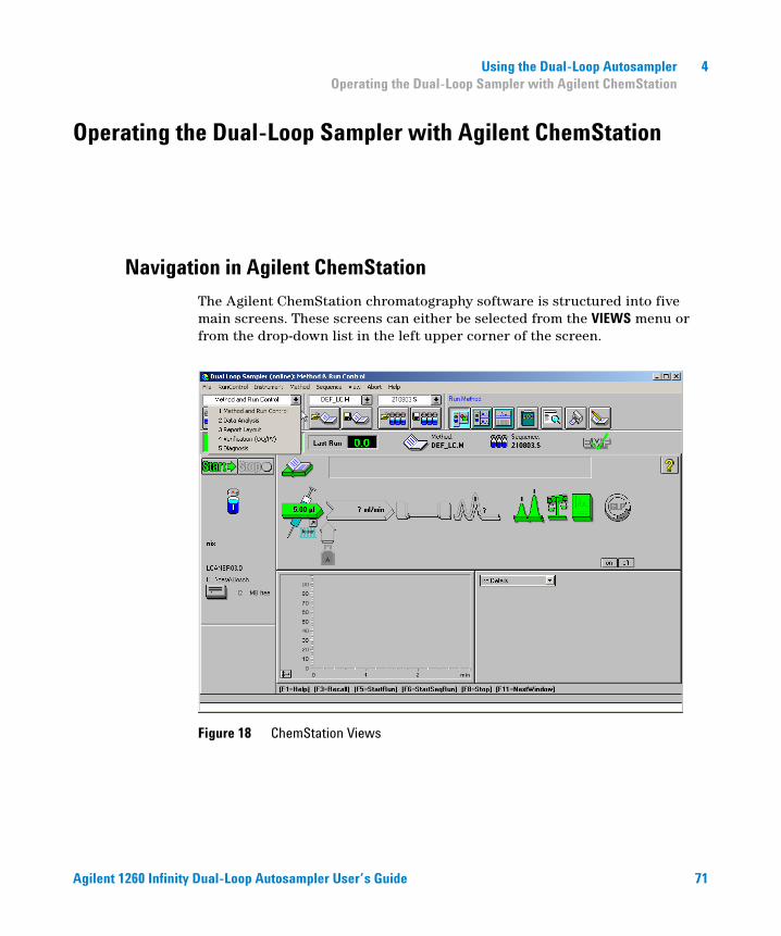
The Agilent ChemStation chromatography software is structured into five main screens. These screens can either be selected from the VIEWS menu or from the drop-down list in the left upper corner of the screen.
Figure 18 ChemStation Views
Agilent 1260 Infinity Dual-Loop Autosampler User’s Guide 71
4 Using the Dual-Loop Autosampler Operating the Dual-Loop Sampler with Agilent ChemStation
Configuring the Dual-Loop Sampler with ChemStation
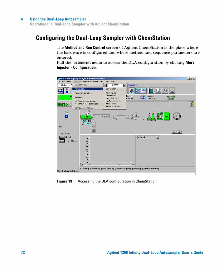
The Method and Run Control screen of Agilent ChemStation is the place where the hardware is configured and where method and sequence parameters are entered. Pull the Instrument menu to access the DLA configuration by clicking More Injector - Configuration.
Figure 19 Accessing the DLA configuration in ChemStation
72 Agilent 1260 Infinity Dual-Loop Autosampler User’s Guide
Using the Dual-Loop Autosampler 4 Operating the Dual-Loop Sampler with Agilent ChemStation
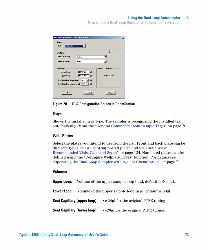
Figure 20 DLA Configuration Screen in ChemStation
Trays
Shows the installed tray type. The sampler is recognizing the installed tray automatically. Mind the “General Comments about Sample Trays” on page 70
Well-Plates
Select the plates you intend to use from the list. Front and back plate can be different types. For a list of supported plates and vials see “List of Recommended Vials, Caps and Septa” on page 124. Non-listed plates can be defined using the “Configure Wellplate Types” function. For details see “Operating the Dual-Loop Sampler with Agilent ChemStation” on page 71
Volumes
Upper Loop: Volume of the upper sample loop in µl, default is 5000µl.
Lower Loop: Volume of the upper sample loop in µl, default is 50µl
Seat Capillary (upper loop): •c 24µl for the original PTFE tubing
Seat Capillary (lower loop): •c20µl for the original PTFE tubing.
Agilent 1260 Infinity Dual-Loop Autosampler User’s Guide 73
4 Using the Dual-Loop Autosampler Operating the Dual-Loop Sampler with Agilent ChemStation
For analytical applications with limited sample volume the seat tubings can be replaced by stainless steel seat capillaries with 0,25mm ID
Additional Configuration and Control Functions
Reset Injector
Use this command to recover the sampler from error conditions and to move all subassemblies into a defined state. When executing this command the needle arm moves into the seat of the active loop (as defined in the currently loaded method), the 10-port valve switches the active loop to mainpass and the plunger of the metering device goes to it’s front position.
Needle Home
Switches the 10-port valve to bypass, moves the Needle arm out of the needle seat and places it into an elevated position behind the wash port. This command is useful if unrestricted access to the sample tray is needed.
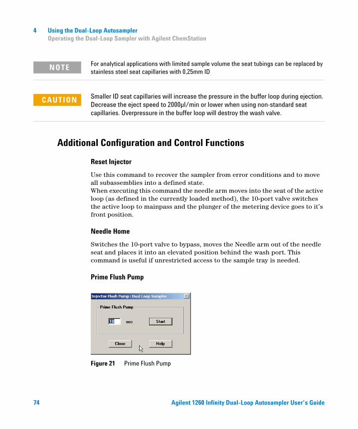
Prime Flush Pump
Figure 21 Prime Flush Pump
NOTE
CAUTION Smaller ID seat capillaries will increase the pressure in the buffer loop during ejection. Decrease the eject speed to 2000µl/min or lower when using non-standard seat capillaries. Overpressure in the buffer loop will destroy the wash valve.
74 Agilent 1260 Infinity Dual-Loop Autosampler User’s Guide
Using the Dual-Loop Autosampler 4 Operating the Dual-Loop Sampler with Agilent ChemStation
Put the end of peristaltic pump intake tubing into a bottle with needle wash solvent and place it into the solvent cabinet In case the same solvent is used to wash the outside of the needle and buffer loop and inside of the needle, one bottle can be used for both. Prime the peristaltic pump for a given time (1 - 1000 seconds) to remove air and previously used solvent. Since the needle wash solvent is drained through the wash port, ensure proper routing of the corrugated waste tubing.
Use External Injector
This function allows to start the run from an external device which is connected to APG start/stop connector of any Agilent 1260 Infinity module. When Use External Injector is activated the autosampler icon turn grey in Agilent ChemStation GUI and the sampler is ignored.
Purge Syringe
This command allows to purge the metering device interactively. Doing so is e.g. required when changing the flush solvent or to remove air bubbles. For an in-depth discussion of this function read “Purging the Syringe” on page 59
Solvent Bottle Filling
Tracks the filling of the flush solvent bottle and inhibits further analysis or generates an error condition when certain solvent limits are reached.
Agilent 1260 Infinity Dual-Loop Autosampler User’s Guide 75
4 Using the Dual-Loop Autosampler Operating the Dual-Loop Sampler with Agilent ChemStation
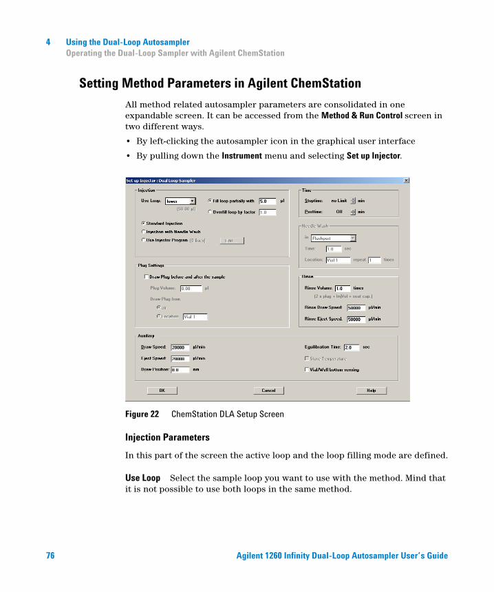
Setting Method Parameters in Agilent ChemStation
All method related autosampler parameters are consolidated in one expandable screen. It can be accessed from the Method & Run Control screen in two different ways.
• By left-clicking the autosampler icon in the graphical user interface
• By pulling down the Instrument menu and selecting Set up Injector.
Figure 22 ChemStation DLA Setup Screen
Injection Parameters
In this part of the screen the active loop and the loop filling mode are defined.
Use Loop Select the sample loop you want to use with the method. Mind that it is not possible to use both loops in the same method.
76 Agilent 1260 Infinity Dual-Loop Autosampler User’s Guide
Using the Dual-Loop Autosampler 4 Operating the Dual-Loop Sampler with Agilent ChemStation
Fill loop partially with Use this injection mode if the intended injection volume is smaller than the volume of the selected sample loop. Partial loop filling is a useful mode if only limited quantities of sample are available and diminished peak area accuracy and reproducibility are not critical. For an in-depth discussion see “Loop Filling Modes” on page 26
Overfill loop This is the preferred mode of operation if you are aiming for highest peak area accuracy and reproducibility. The disadvantage is that sample is wasted for overfilling the sample loop. Typical overfill factors for best results are 3 - 5. See also “Loop Filling Modes” on page 26
Standard Injection Checking this button makes the autosampler use the default injection sequence which is a good choice for most applications.
Injection with Needle Wash When this radio button is clicked the Needle Wash parameters on the right hand side of the input screen become accessible.
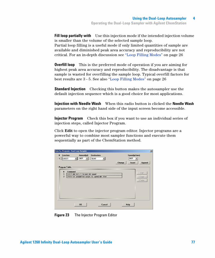
Injector Program Check this box if you want to use an individual series of injection steps, called Injector Program.
Click Edit to open the injector program editor. Injector programs are a powerful way to combine most sampler functions and execute them sequentially as part of the ChemStation method.
Figure 23 The Injector Program Editor
Agilent 1260 Infinity Dual-Loop Autosampler User’s Guide 77
4 Using the Dual-Loop Autosampler Operating the Dual-Loop Sampler with Agilent ChemStation
An injector program consists of one instruction per line. Select the desired function from the Function drop-down menu and add it by clicking Insert or Append. To change a program line highlight it and hit Change. Cut, Copy and Paste are useful for reuse injector program lines. To check and transfer the injector program to the autosampler press OK.
The maximum number of injector program lines is limited by the amount of free memory on the Dual-Loop Sampler mainboard. If needed additional memory can be allocated to extend the available space for the injector program from approximately 60 lines to 120 lines. However, in that case the injector program cannot be processed by the Instant Pilot. For details consult the ChemStation help function.
Plug Setting
This parameter allows to enclose the sample into either plugs of air or of any desired liquid
Plug Volume Defines the volume of each plug. Typical plug volumes are 5 - 10% of the sample volume.
Draw Plug from This parameter offer the choice of either air plugs or plugs of any solvent from a given vessel position.
Needle Wash
Needle wash minimizes carryover by dipping the needle into either the flush port or any sample location. The flush port is fed by a peristaltic pump. Needle flush solvent can either be taken from the flush solvent bottle or a different vessel.
CAUTION The ChemStation code validation check performs a basic syntax check. Conceptional weaknesses or wrong parameter values won’t be detected and remain the responsibility of the user.
78 Agilent 1260 Infinity Dual-Loop Autosampler User’s Guide
Using the Dual-Loop Autosampler 4 Operating the Dual-Loop Sampler with Agilent ChemStation
Rinse
Complementing the Wash command, Rinse allows to flush buffer loop and the inside of the needle.
Rinse Volume
V flush( ) 2V plug( ) V sample( ) V seatcap( ) V valve( )+ + +=
Defines the relative rinse volume for buffer loop and needle according to the following formula:
with
Rinse Draw Speed, Rinse Eject Speed Speed at which the sampler draws and ejects flush solvent. As small volume deviations are not critical, higher speeds as when drawing sample can be used. Limits are 350 µl/min to 50,000 µl/min. Default is 50.000µl/min.
More Method Parameters
By clicking More the windows expands and auxiliary parameters become visible.
Draw Speed Defines at what flow rate liquid is sucked into the buffer loop. Valid entries are 350 µl/min - 50,000 µl/min.
Eject Speed Defines at what flow rate the content of the buffer loop is ejected in to the sample loop, any vessel or to waste. Valid entries are 350 µl/min - 50,000 µl/min.
V(flush) = Flush volume
V(plug) = Volume of buffer or air plug
V(sample) = Volume of injected sample
V(seatcap) = Volume of installed seat tubing
V(valve) = Volume of valve stator ports and rotor groove (4,9 µl)
Agilent 1260 Infinity Dual-Loop Autosampler User’s Guide 79
4 Using the Dual-Loop Autosampler Operating the Dual-Loop Sampler with Agilent ChemStation
Draw Position Allows to change the needle position in sample vessels in the range of -10 mm (10 mm lower) to +50 mm (50 mm higher). The use of this parameter requires careful consideration as improper use may damage needle and sample vessel.
Equilibration Time Defines for how many seconds the sampler waits for pressure equilibration in sample vial and buffer loop until it proceeds with the next injection step. This parameter allows to optimize reproducibility for viscous samples, higher draw speeds and large injection volumes.
Store Temperature Stores the temperature of the sample compartment as part of the data file (requires optional Agilent 1290 Infinity Thermostat).
Vial/Well Bottom Sensing If this box is ticked the sampler auto detects the bottom of the sample vessel. A few conditions are not suitable for this function:
• The needle moves off-center into the well with spherical or conical bottom.
• The vial plate/well plate has not been defined properly.
The latter point is of special importance because the sampler moves the needle at high speed into the vessel and slows down only a few millimeters above the bottom. At low speed the needle moves further down until the sampler notices an increase in motor current.
CAUTION Using Bottom Sensing with a inaccurate well definitions may cause the sampler to slam the needle into the bottom of the sample vessel causing damage to the needle assembly!
80 Agilent 1260 Infinity Dual-Loop Autosampler User’s Guide
Using the Dual-Loop Autosampler 4 Achieving the Best Recovery Results with the Agilent 1260 Infinity Dual-Loop Autosampler PS
Achieving the Best Recovery Results with the Agilent 1260 Infinity Dual-Loop Autosampler PS
Introduction
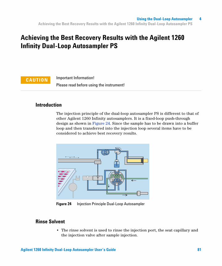
The injection principle of the dual-loop autosampler PS is different to that of other Agilent 1260 Infinity autosamplers. It is a fixed-loop push-through design as shown in Figure 24. Since the sample has to be drawn into a buffer loop and then transferred into the injection loop several items have to be considered to achieve best recovery results.
Rinse Solvent
• The rinse solvent is used to rinse the injection port, the seat capillary and the injection valve after sample injection.
CAUTION Important Information!
Please read before using the instrument!
Figure 24 Injection Principle Dual-Loop Autosampler
Agilent 1260 Infinity Dual-Loop Autosampler User’s Guide 81
4 Using the Dual-Loop Autosampler Achieving the Best Recovery Results with the Agilent 1260 Infinity Dual-Loop Autosampler PS
• To avoid precipitation problems, use a solvent in which the sample is readily soluble. For reversed-phase chromatography this could be acetonitrile, methanol or DMSO/acetonitrile 50:50 v/v, for example (pure DMSO is not recommended due to its high viscosity, see "Sample draw and eject speed").
• We strongly recommend to use the Rinse function subsequently to each injection. The rinse volume, which is calculated from the injection volume and a user-defined factor, should be at least 300 µL.
• The syringe should be purged at least 5 times using the Purge Syringe command from the Instrument/More Injector menu prior to the first run of a sequence.
Flush Solvent
The flush solvent is used to flush the needle's exterior prior to the injection of the sample. Therefore a solvent should be used, in which the sample is readily soluble. For a list of solvents compatible with the tubing of the peristaltic pump see Table 6 below.
Table 6 Solvents Compatible with Tubings
Solvent PharMed *
* Pre-installed
Silicone †
† Can be ordered (5042-8507)
Acetic acid > 5% A B A Fully compatible
Acetone D D
Acetonitrile A - B Minor reaction, e.g. slight corrosion or discolorationHexane, Heptane C -
NH4 acetate C - C Not recommended for continuous use. Swelling/shrinkage, loss of strength.
Ethanol C B
Formic acid A C
MeOH D A D Severe reaction, not recommended for usePropanol C A
Trichloroacetic acid D D
Water A A
82 Agilent 1260 Infinity Dual-Loop Autosampler User’s Guide
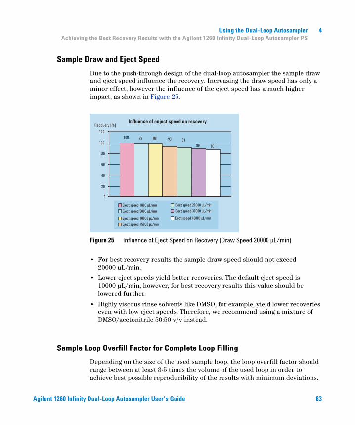
Using the Dual-Loop Autosampler 4 Achieving the Best Recovery Results with the Agilent 1260 Infinity Dual-Loop Autosampler PS
Sample Draw and Eject Speed
Due to the push-through design of the dual-loop autosampler the sample draw and eject speed influence the recovery. Increasing the draw speed has only a minor effect, however the influence of the eject speed has a much higher impact, as shown in Figure 25.
• For best recovery results the sample draw speed should not exceed 20000 µL/min.
• Lower eject speeds yield better recoveries. The default eject speed is 10000 µL/min, however, for best recovery results this value should be lowered further.
• Highly viscous rinse solvents like DMSO, for example, yield lower recoveries even with low eject speeds. Therefore, we recommend using a mixture of DMSO/acetonitrile 50:50 v/v instead.
Sample Loop Overfill Factor for Complete Loop Filling
Depending on the size of the used sample loop, the loop overfill factor should range between at least 3-5 times the volume of the used loop in order to achieve best possible reproducibility of the results with minimum deviations.
Figure 25 Influence of Eject Speed on Recovery (Draw Speed 20000 µL/min)
100 98 98 93 9189 88
0
20
40
60
80
100
120
Eject speed 20000 µL/min
Eject speed 30000 µL/min
100 98 98 93 9189 88
Eject speed 40000 µL/min
Recovery [%]
Eject speed 1000 µL/min
Eject speed 5000 µL/min
Eject speed 10000 µL/min
Eject speed 15000 µL/min
Influence of enject speed on recovery
Agilent 1260 Infinity Dual-Loop Autosampler User’s Guide 83
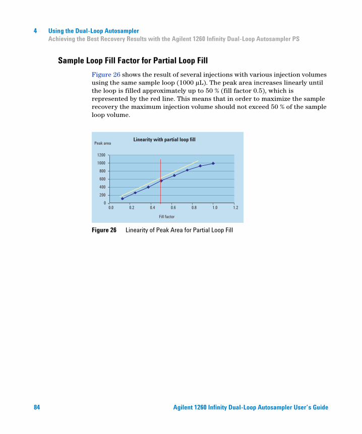
4 Using the Dual-Loop Autosampler Achieving the Best Recovery Results with the Agilent 1260 Infinity Dual-Loop Autosampler PS
Sample Loop Fill Factor for Partial Loop Fill
Figure 26 shows the result of several injections with various injection volumes using the same sample loop (1000 µL). The peak area increases linearly until the loop is filled approximately up to 50 % (fill factor 0.5), which is represented by the red line. This means that in order to maximize the sample recovery the maximum injection volume should not exceed 50 % of the sample loop volume.
Figure 26 Linearity of Peak Area for Partial Loop Fill
0
200
400
600
800
1000
1200
0.0 0.2 0.4 0.6 0.8 1.0 1.2
Fill factor
Peak areaLinearity with partial loop fill
84 Agilent 1260 Infinity Dual-Loop Autosampler User’s Guide
Agilent 1260 Infinity Dual-Loop AutosamplerUser’s Guide
5Troubleshooting Overview
Overview 82
Status Indicators 84
This chapter gives an Overview to Troubleshooting the Dual Loop Autosampler.
85Agilent Technologies
5 Troubleshooting Overview Overview
Overview
Status Indicators
The Dual Looop Autosampler is provided with two status indicators which indicate the operational state (prerun, not ready, run, and error states) of the instrument. The status indicators provide a quick visual check of the operation of the Dual Loop Autosampler (see “Status Indicators” on page 84).
Error Messages
In the event of an electronic, mechanical or hydraulic failure, the instrument generates an error message in the user interface. For each message, a short description of the failure, a list of probable causes of the problem, and a list of suggested actions to fix the problem are provided (see “Error Messages” in the Service Manual).
Maintenance Functions
The maintenance functions position the transport unit and needle carrier assembly in certain positions for maintenance, homing or parking (see “Maintenance Functions” in the Service Manual).
Transport Unit Self Alignment
The transport unit alignment with the transport unit and the well-plate tray is required to compensate for larger deviations in positioning the needle carrier assembly.
86 Agilent 1260 Infinity Dual-Loop Autosampler User’s Guide
Troubleshooting Overview 5 Overview
The transport unit self alignment is required after disassembling the system or when transport unit, needle carrier assembly or MTP main board are replaced. This function is in the diagnose screen of the Agilent ChemStation or the Instant Pilot.
WARNING The sample transport self alignment requires one of the 2-well-plate trays (Part Number: G2258-44502 or G2258-60001), but well plates MUST NOT be installed!
Agilent 1260 Infinity Dual-Loop Autosampler User’s Guide 87
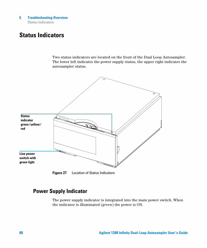
5 Troubleshooting Overview Status Indicators
Status Indicators
Two status indicators are located on the front of the Dual Loop Autosampler. The lower left indicates the power supply status, the upper right indicates the autosampler status.
Power Supply Indicator
The power supply indicator is integrated into the main power switch. When the indicator is illuminated (green) the power is ON.
Figure 27 Location of Status Indicators
Status indicatorgreen/yellow/red
Line power switch with green light
88 Agilent 1260 Infinity Dual-Loop Autosampler User’s Guide
Troubleshooting Overview 5 Status Indicators
Instrument Status Indicator
The instrument status indicator indicates one of four possible instrument conditions:
• When the status indicator is OFF (and power switch light is on), the instrument is in a prerun condition, and is ready to begin an analysis.
• A green status indicator indicates the instrument is performing an analysis (run mode).
• A yellow status indicator indicates a not-ready condition. The instrument is in a not-ready state when it is waiting for a specific condition to be reached or completed (for example, front door not closed), or while a self-test procedure is running.
• An error condition is indicated when the status indicator is red. An error condition indicates the instrument has detected an internal problem which affects correct operation of the instrument. Usually, an error condition requires attention (for example, leak, defective internal components). An error condition always interrupts the analysis.
Agilent 1260 Infinity Dual-Loop Autosampler User’s Guide 89

5 Troubleshooting Overview Status Indicators
90 Agilent 1260 Infinity Dual-Loop Autosampler User’s Guide
Agilent 1260 Infinity Dual-Loop AutosamplerUser’s Guide
6Introduction to Repairing the Dual-Loop Autosampler
Cleaning the Dual-Loop Autosampler 93
Using the ESD Strap 93
This chapter gives an Introduction to Repairing the Dual Loop Autosampler.
91Agilent Technologies
6 Introduction to Repairing the Dual-Loop Autosampler Introduction to Repairing the Dual-Loop Autosampler
Introduction to Repairing the Dual-Loop Autosampler
Simple Repairs
The Dual-Loop Autosampler is designed for easy repair. All maintenance tasks and most easy repairs such as changing rotor seal, needle assembly, needle seat assembly or tubings can be done from the front of the instrument without removing the module from the system stack. These proceduress are described in “Maintenance Procedures and Simple Repairs” on page 96.
Exchanging Internal Parts
Some repairs require the replacement of defective internal parts. In these cases it is necessary to remove the autosampler from the stack, take the covers off and disassemble the module. These repairs are described in “Exchanging Internal Parts” in the Service Manual.
WARNING When opening capillary or tube fittings solvents may leak out. Please observe appropriate safety procedures (for example, goggles, safety gloves and protective clothing) as described in the material handling and safety data sheet supplied by the solvent vendor, especially when toxic or hazardous solvents are used.
WARNING Regularly inspect all plastic tubings of the sampler and exchange them if they are worn out or show visible signs of damage.
WARNING To prevent personal injury, the power cable must be removed from the instrument before opening the top cover. Do not connect the power cable to the sampler while the cover is OFF.
92 Agilent 1260 Infinity Dual-Loop Autosampler User’s Guide
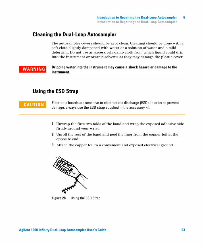
Introduction to Repairing the Dual-Loop Autosampler 6 Introduction to Repairing the Dual-Loop Autosampler
Cleaning the Dual-Loop Autosampler
The autosampler covers should be kept clean. Cleaning should be done with a soft cloth slightly dampened with water or a solution of water and a mild detergent. Do not use an excessively damp cloth from which liquid could drip into the instrument or organic solvents as they may damage the plastic cover.
Using the ESD Strap
1 Unwrap the first two folds of the band and wrap the exposed adhesive side firmly around your wrist.
2 Unroll the rest of the band and peel the liner from the copper foil at the opposite end.
3 Attach the copper foil to a convenient and exposed electrical ground.
WARNING Dripping water into the instrument may cause a shock hazard or damage to the instrument.
CAUTION Electronic boards are sensitive to electrostatic discharge (ESD). In order to prevent damage, always use the ESD strap supplied in the accessory kit.
Figure 28 Using the ESD Strap
Agilent 1260 Infinity Dual-Loop Autosampler User’s Guide 93

6 Introduction to Repairing the Dual-Loop Autosampler Introduction to Repairing the Dual-Loop Autosampler
94 Agilent 1260 Infinity Dual-Loop Autosampler User’s Guide
Agilent 1260 Infinity Dual-Loop AutosamplerUser’s Guide
7Maintaining the Dual-Loop Autosampler
Maintenance Procedures and Simple Repairs 96
Replacing the Buffer Loop 104
Replacing the Rotor Seal of the 10-Port Valve 97
Replacing the Needle Assembly 100
Replacing Front Seat/Back Seat Assembly or Seat Tubings 108
Replacing the Peristaltic Pump 110
Exchanging the Needle Carrier Assembly 112
Replacing Seal or Piston of the Metering Unit 115
Exchanging or Installing the (Optional Interface) BCD Board 120
This chapter describes the Maintenance and Simple Repairs of the Dual Loop Autosampler.
95Agilent Technologies
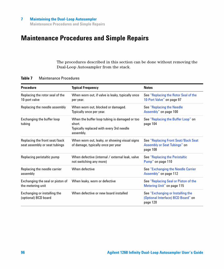
7 Maintaining the Dual-Loop Autosampler Maintenance Procedures and Simple Repairs
Maintenance Procedures and Simple Repairs
The procedures described in this section can be done without removing the Dual-Loop Autosampler from the stack.
Table 7 Maintenance Procedures
Procedure Typical Frequency Notes
Replacing the rotor seal of the 10-port valve
When worn out, if valve is leaky, typically once per year.
See “Replacing the Rotor Seal of the 10-Port Valve” on page 97
Replacing the needle assembly When worn out, blocked or damaged. Typically once per year.
See “Replacing the Needle Assembly” on page 100
Exchanging the buffer loop tubing
When the buffer loop tubing is damaged or too short. Typically replaced with every 3rd needle assembly.
See “Replacing the Buffer Loop” on page 104
Replacing the front seat/back seat assembly or seat tubings
When worn out, leaky, or showing visual signs of damage, typically once per year
See “Replacing Front Seat/Back Seat Assembly or Seat Tubings” on page 108
Replacing peristaltic pump When defective (internal / external leak, valve not switching any more)
See “Replacing the Peristaltic Pump” on page 110
Replacing the needle carrier assembly
When defective See “Exchanging the Needle Carrier Assembly” on page 112
Exchanging the seal or piston of the metering unit
When leaky, worn or defective See “Replacing Seal or Piston of the Metering Unit” on page 115
Exchanging or installing the (optional) BCD board
When defective or new board installed See “Exchanging or Installing the (Optional Interface) BCD Board” on page 120
96 Agilent 1260 Infinity Dual-Loop Autosampler User’s Guide
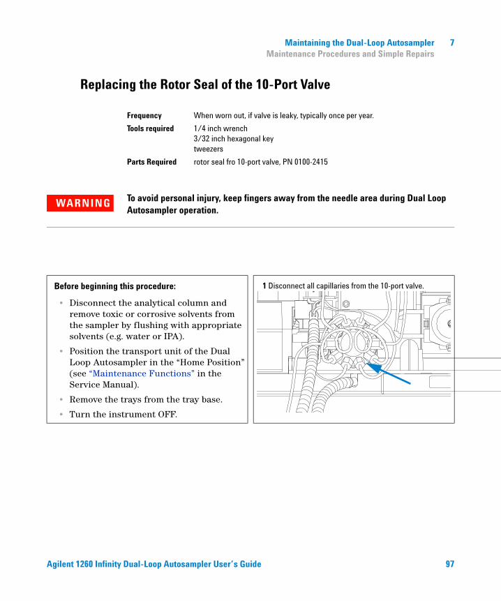
Maintaining the Dual-Loop Autosampler 7 Maintenance Procedures and Simple Repairs
Replacing the Rotor Seal of the 10-Port Valve
Frequency When worn out, if valve is leaky, typically once per year.
Tools required 1/4 inch wrench3/32 inch hexagonal keytweezers
Parts Required rotor seal fro 10-port valve, PN 0100-2415
WARNING To avoid personal injury, keep fingers away from the needle area during Dual Loop Autosampler operation.
Before beginning this procedure:
• Disconnect the analytical column and remove toxic or corrosive solvents from the sampler by flushing with appropriate solvents (e.g. water or IPA).
• Position the transport unit of the Dual Loop Autosampler in the “Home Position” (see “Maintenance Functions” in the Service Manual).
• Remove the trays from the tray base.
• Turn the instrument OFF.
1 Disconnect all capillaries from the 10-port valve.
Agilent 1260 Infinity Dual-Loop Autosampler User’s Guide 97
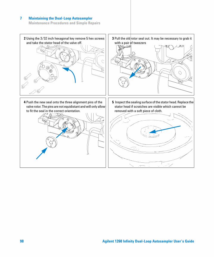
7 Maintaining the Dual-Loop Autosampler Maintenance Procedures and Simple Repairs
2 Using the 3/32 inch hexagonal key remove 5 hex screws and take the stator head of the valve off.
3 Pull the old rotor seal out. It may be necessary to grab it with a pair of tweezers
4 Push the new seal onto the three alignment pins of the valve rotor. The pins are not equidistant and will only allow to fit the seal in the correct orientation.
5 Inspect the sealing surface of the stator head. Replace the stator head if scratches are visible which cannot be removed with a soft piece of cloth.
98 Agilent 1260 Infinity Dual-Loop Autosampler User’s Guide
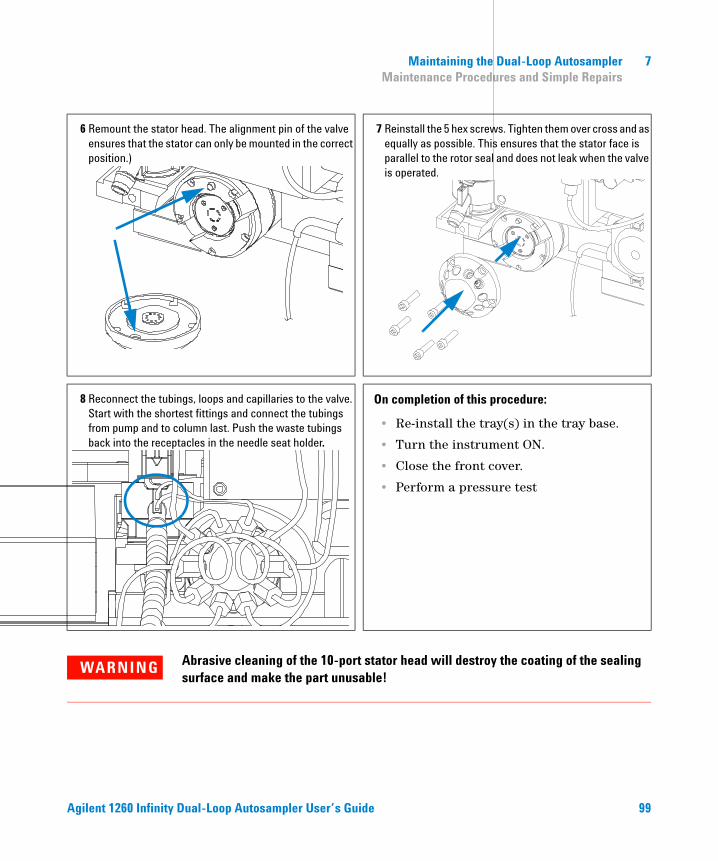
Maintaining the Dual-Loop Autosampler 7 Maintenance Procedures and Simple Repairs
6 Remount the stator head. The alignment pin of the valve ensures that the stator can only be mounted in the correct position.)
7 Reinstall the 5 hex screws. Tighten them over cross and as equally as possible. This ensures that the stator face is parallel to the rotor seal and does not leak when the valve is operated.
8 Reconnect the tubings, loops and capillaries to the valve. Start with the shortest fittings and connect the tubings from pump and to column last. Push the waste tubings back into the receptacles in the needle seat holder.
On completion of this procedure:
• Re-install the tray(s) in the tray base.
• Turn the instrument ON.
• Close the front cover.
• Perform a pressure test
WARNING Abrasive cleaning of the 10-port stator head will destroy the coating of the sealing surface and make the part unusable!
Agilent 1260 Infinity Dual-Loop Autosampler User’s Guide 99
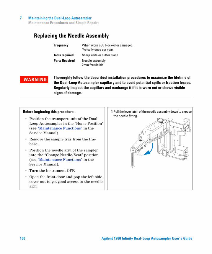
7 Maintaining the Dual-Loop Autosampler Maintenance Procedures and Simple Repairs
Replacing the Needle Assembly
Frequency When worn out, blocked or damaged. Typically once per year.
Tools required Sharp knife or cutter blade
Parts Required Needle assembly2mm ferrule kit
WARNING Thoroughly follow the described installation procedures to maximize the lifetime of the Dual-Loop Autosampler capillary and to avoid potential spills or fraction losses. Regularly inspect the capillary and exchange it if it is worn out or shows visible signs of damage.
Before beginning this procedure:
• Position the transport unit of the Dual Loop Autosampler in the “Home Position” (see “Maintenance Functions” in the Service Manual).
• Remove the sample tray from the tray base.
• Position the needle arm of the sampler into the “Change Needle/Seat” position (see “Maintenance Functions” in the Service Manual).
• Turn the instrument OFF.
• Open the front door and pop the left side cover out to get good access to the needle arm.
1 Pull the lever latch of the needle assembly down to expose the needle fitting.
100 Agilent 1260 Infinity Dual-Loop Autosampler User’s Guide
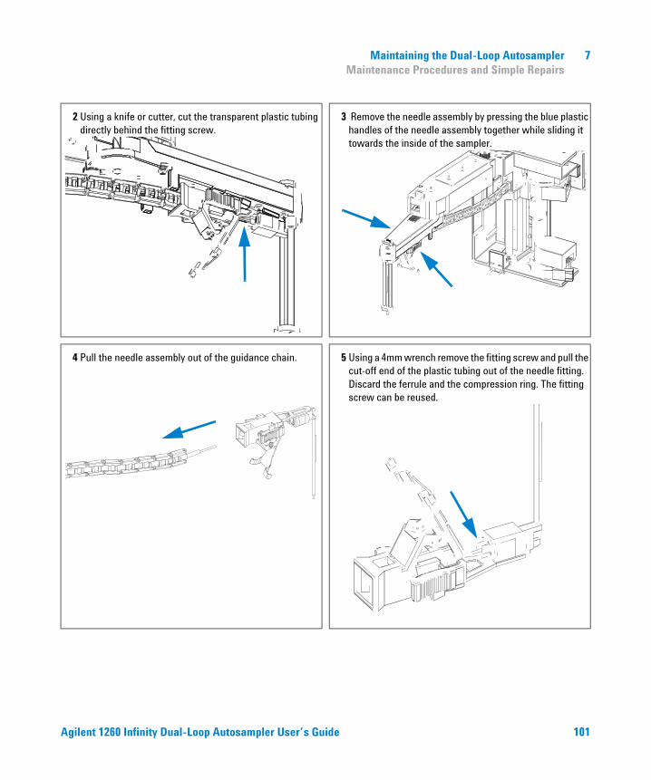
Maintaining the Dual-Loop Autosampler 7 Maintenance Procedures and Simple Repairs
2 Using a knife or cutter, cut the transparent plastic tubing directly behind the fitting screw.
3 Remove the needle assembly by pressing the blue plastic handles of the needle assembly together while sliding it towards the inside of the sampler.
4 Pull the needle assembly out of the guidance chain.
5 Using a 4mm wrench remove the fitting screw and pull the cut-off end of the plastic tubing out of the needle fitting. Discard the ferrule and the compression ring. The fitting screw can be reused.
Agilent 1260 Infinity Dual-Loop Autosampler User’s Guide 101
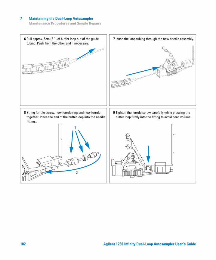
7 Maintaining the Dual-Loop Autosampler Maintenance Procedures and Simple Repairs
6 Pull approx. 5cm (2 “) of buffer loop out of the guide tubing. Push from the other end if necessary.
7 push the loop tubing through the new needle assembly.
8 String ferrule screw, new ferrule ring and new ferrule together. Place the end of the buffer loop into the needle fitting...
1
2
9 Tighten the ferrule screw carefully while pressing the buffer loop firmly into the fitting to avoid dead volume.
102 Agilent 1260 Infinity Dual-Loop Autosampler User’s Guide
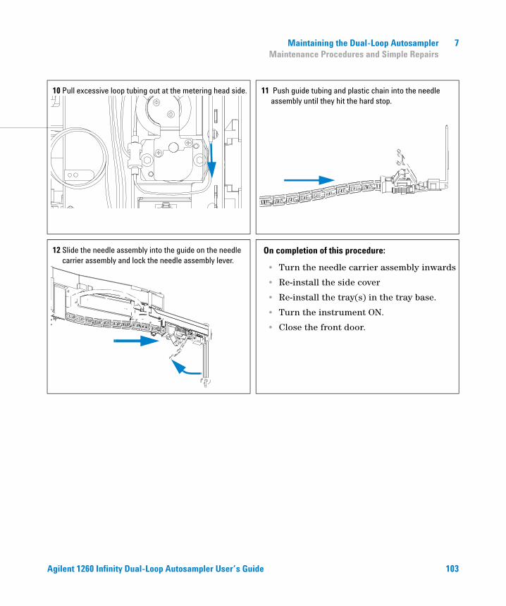
Maintaining the Dual-Loop Autosampler 7 Maintenance Procedures and Simple Repairs
10 Pull excessive loop tubing out at the metering head side. 11 Push guide tubing and plastic chain into the needle assembly until they hit the hard stop.
12 Slide the needle assembly into the guide on the needle carrier assembly and lock the needle assembly lever.
On completion of this procedure:
• Turn the needle carrier assembly inwards
• Re-install the side cover
• Re-install the tray(s) in the tray base.
• Turn the instrument ON.
• Close the front door.
Agilent 1260 Infinity Dual-Loop Autosampler User’s Guide 103
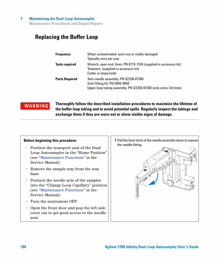
7 Maintaining the Dual-Loop Autosampler Maintenance Procedures and Simple Repairs
Replacing the Buffer Loop
Frequency When contaminated, worn out or visibly damagedTypically once per year
Tools required Wrench, open end, 4mm, PN 8710-1534 (supplied in accessory kit)Tweezers, (supplied in accessory kit)Cutter or sharp knife
Parts Required Twin needle assembly, PN G2258-873062mm fitting kit, PN 5065-9950Upper loop tubing assembly, PN G2258-87300 (only every 3rd time)
WARNING Thoroughly follow the described installation procedures to maximize the lifetime of the buffer loop tubing and to avoid potential spills. Regularly inspect the tubings and exchange them if they are worn out or show visible signs of damage.
Before beginning this procedure:
• Position the transport unit of the Dual Loop Autosampler in the “Home Position” (see “Maintenance Functions” in the Service Manual).
• Remove the sample tray from the tray base.
• Position the needle arm of the sampler into the “Change Loop Capillary” position (see “Maintenance Functions” in the Service Manual).
• Turn the instrument OFF.
• Open the front door and pop the left side cover out to get good access to the needle arm.
1 Pull the lever latch of the needle assembly down to expose the needle fitting.
104 Agilent 1260 Infinity Dual-Loop Autosampler User’s Guide
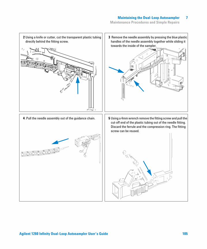
Maintaining the Dual-Loop Autosampler 7 Maintenance Procedures and Simple Repairs
2 Using a knife or cutter, cut the transparent plastic tubing directly behind the fitting screw.
3 Remove the needle assembly by pressing the blue plastic handles of the needle assembly together while sliding it towards the inside of the sampler.
4 .Pull the needle assembly out of the guidance chain.
5 Using a 4mm wrench remove the fitting screw and pull the cut-off end of the plastic tubing out of the needle fitting. Discard the ferrule and the compression ring. The fitting screw can be reused.
Agilent 1260 Infinity Dual-Loop Autosampler User’s Guide 105
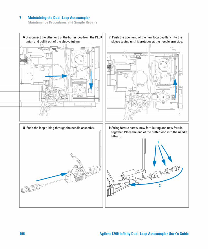
7 Maintaining the Dual-Loop Autosampler Maintenance Procedures and Simple Repairs
6 Disconnect the other end of the buffer loop from the PEEK union and pull it out of the sleeve tubing.
7 Push the open end of the new loop capillary into the sleeve tubing until it protudes at the needle arm side.
8 Push the loop tubing through the needle assembly. 9 String ferrule screw, new ferrule ring and new ferrule together. Place the end of the buffer loop into the needle fitting...
1
2
106 Agilent 1260 Infinity Dual-Loop Autosampler User’s Guide
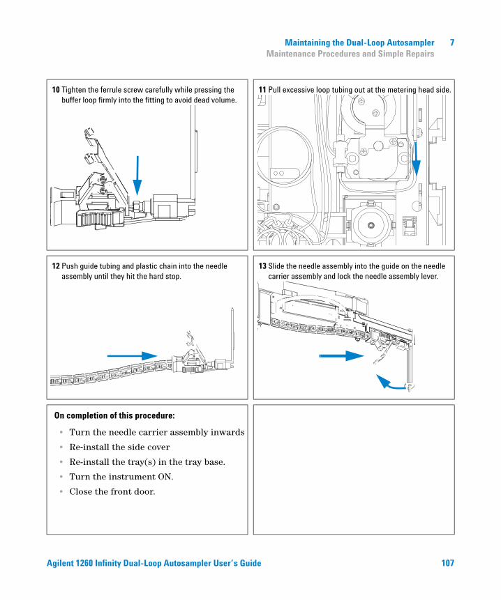
Maintaining the Dual-Loop Autosampler 7 Maintenance Procedures and Simple Repairs
10 Tighten the ferrule screw carefully while pressing the buffer loop firmly into the fitting to avoid dead volume.
11 Pull excessive loop tubing out at the metering head side.
12 Push guide tubing and plastic chain into the needle assembly until they hit the hard stop.
13 Slide the needle assembly into the guide on the needle carrier assembly and lock the needle assembly lever.
On completion of this procedure:
• Turn the needle carrier assembly inwards
• Re-install the side cover
• Re-install the tray(s) in the tray base.
• Turn the instrument ON.
• Close the front door.
Agilent 1260 Infinity Dual-Loop Autosampler User’s Guide 107
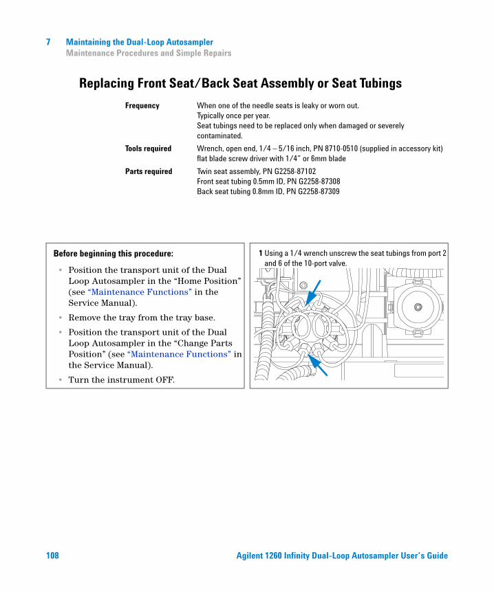
7 Maintaining the Dual-Loop Autosampler Maintenance Procedures and Simple Repairs
Replacing Front Seat/Back Seat Assembly or Seat Tubings
Frequency When one of the needle seats is leaky or worn out.Typically once per year.Seat tubings need to be replaced only when damaged or severely contaminated.
Tools required Wrench, open end, 1/4 – 5/16 inch, PN 8710-0510 (supplied in accessory kit)flat blade screw driver with 1/4” or 6mm blade
Parts required Twin seat assembly, PN G2258-87102Front seat tubing 0.5mm ID, PN G2258-87308Back seat tubing 0.8mm ID, PN G2258-87309
Before beginning this procedure:
• Position the transport unit of the Dual Loop Autosampler in the “Home Position” (see “Maintenance Functions” in the Service Manual).
• Remove the tray from the tray base.
• Position the transport unit of the Dual Loop Autosampler in the “Change Parts Position” (see “Maintenance Functions” in the Service Manual).
• Turn the instrument OFF.
1 Using a 1/4 wrench unscrew the seat tubings from port 2 and 6 of the 10-port valve.
108 Agilent 1260 Infinity Dual-Loop Autosampler User’s Guide
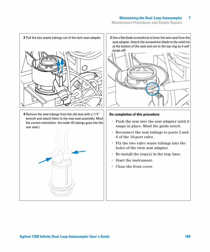
Maintaining the Dual-Loop Autosampler 7 Maintenance Procedures and Simple Repairs
2 Pull the two waste tubings out of the twin seat adapter.
.
3 Use a flat blade screwdriver to lever the twin seat from the seat adapter. Attach the screwdriver blade to the solid rim at the bottom of the seat and not to the top ring as it will break off!
4 Remove the seat tubings from the old seat with a 1/4” wrench and attach them to the new seat assembly. Mind the correct orientation. the wider ID tubings goes into the rear seat.)
On completion of this procedure:
• Push the seat into the seat adapter until it snaps in place. Mind the guide notch.
• Reconnect the seat tubings to ports 2 and 6 of the 10-port valve.
• Fix the two valve waste tubings into the holes of the twin seat adapter.
• Re-install the tray(s) in the tray base.
• Start the instrument.
• Close the front cover.
Agilent 1260 Infinity Dual-Loop Autosampler User’s Guide 109
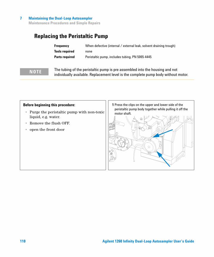
7 Maintaining the Dual-Loop Autosampler Maintenance Procedures and Simple Repairs
Replacing the Peristaltic Pump
Frequency When defective (internal / external leak, solvent draining trough)
Tools required none
Parts required Peristaltic pump, includes tubing, PN 5065-4445
NOTE The tubing of the peristaltic pump is pre assembled into the housing and not individually available. Replacement level is the complete pump body without motor.
Before beginning this procedure:
• Purge the peristaltic pump with non-toxic liquid, e.g. water.
• Remove the flush OFF.
• open the front door
1 Press the clips on the upper and lower side of the peristaltic pump body together while pulling it off the motor shaft.
110 Agilent 1260 Infinity Dual-Loop Autosampler User’s Guide
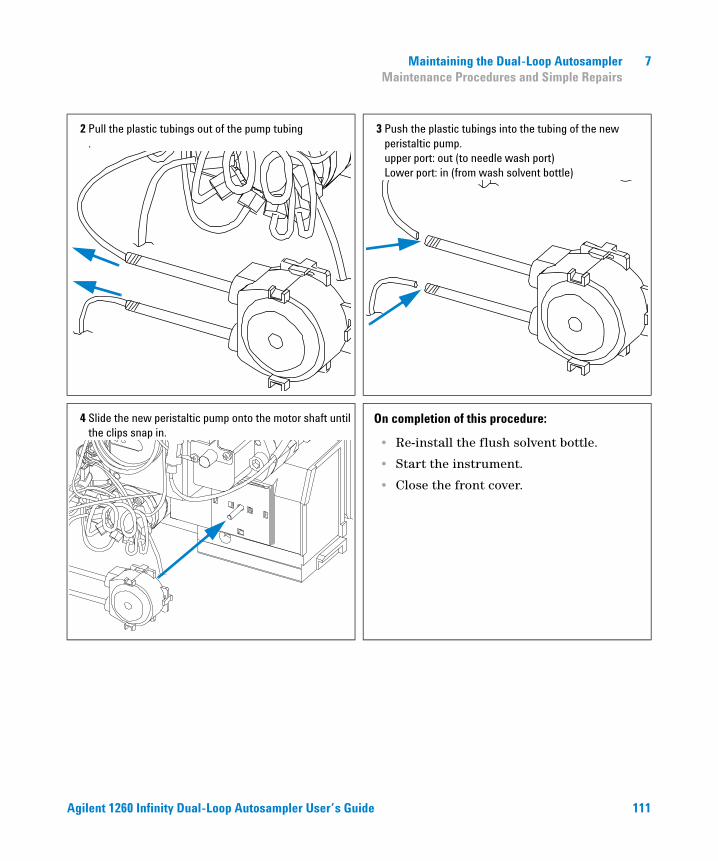
Maintaining the Dual-Loop Autosampler 7 Maintenance Procedures and Simple Repairs
2 Pull the plastic tubings out of the pump tubing .
3 Push the plastic tubings into the tubing of the new peristaltic pump. upper port: out (to needle wash port) Lower port: in (from wash solvent bottle)
4 Slide the new peristaltic pump onto the motor shaft until the clips snap in.
On completion of this procedure:
• Re-install the flush solvent bottle.
• Start the instrument.
• Close the front cover.
Agilent 1260 Infinity Dual-Loop Autosampler User’s Guide 111
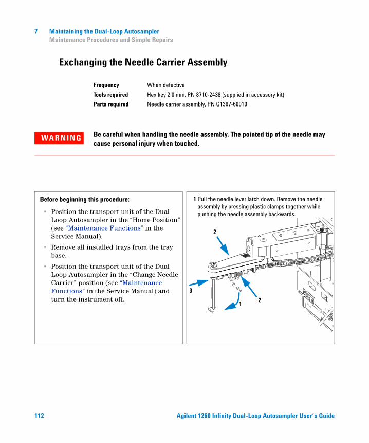
7 Maintaining the Dual-Loop Autosampler Maintenance Procedures and Simple Repairs
Exchanging the Needle Carrier Assembly
Frequency When defective
Tools required Hex key 2.0 mm, PN 8710-2438 (supplied in accessory kit)
Parts required Needle carrier assembly, PN G1367-60010
WARNING Be careful when handling the needle assembly. The pointed tip of the needle may cause personal injury when touched.
Before beginning this procedure:
• Position the transport unit of the Dual Loop Autosampler in the “Home Position” (see “Maintenance Functions” in the Service Manual).
• Remove all installed trays from the tray base.
• Position the transport unit of the Dual Loop Autosampler in the “Change Needle Carrier” position (see “Maintenance Functions” in the Service Manual) and turn the instrument off.
1 Pull the needle lever latch down. Remove the needle assembly by pressing plastic clamps together while pushing the needle assembly backwards.
12
2
3
112 Agilent 1260 Infinity Dual-Loop Autosampler User’s Guide
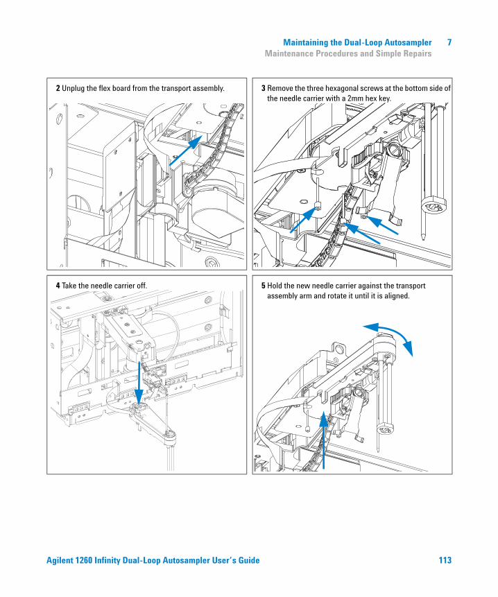
Maintaining the Dual-Loop Autosampler 7 Maintenance Procedures and Simple Repairs
2 Unplug the flex board from the transport assembly. 3 Remove the three hexagonal screws at the bottom side of the needle carrier with a 2mm hex key.
4 Take the needle carrier off. 5 Hold the new needle carrier against the transport assembly arm and rotate it until it is aligned.
Agilent 1260 Infinity Dual-Loop Autosampler User’s Guide 113
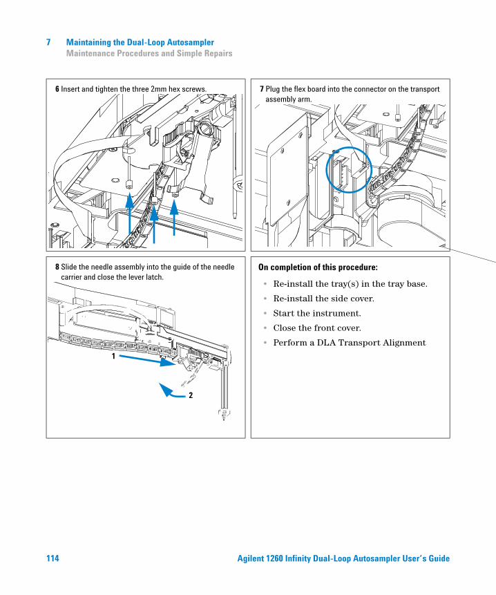
7 Maintaining the Dual-Loop Autosampler Maintenance Procedures and Simple Repairs
6 Insert and tighten the three 2mm hex screws. 7 Plug the flex board into the connector on the transport assembly arm.
8 Slide the needle assembly into the guide of the needle carrier and close the lever latch.
On completion of this procedure:
• Re-install the tray(s) in the tray base.
• Re-install the side cover.
• Start the instrument.
• Close the front cover.
• Perform a DLA Transport Alignment
1
2
114 Agilent 1260 Infinity Dual-Loop Autosampler User’s Guide
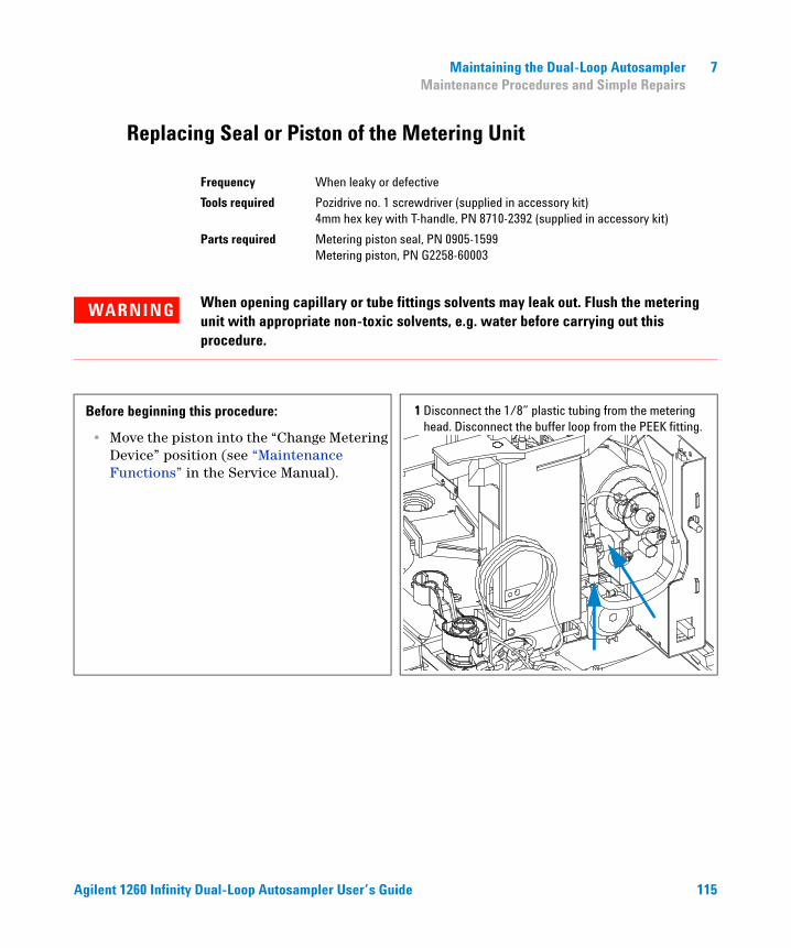
Maintaining the Dual-Loop Autosampler 7 Maintenance Procedures and Simple Repairs
Replacing Seal or Piston of the Metering Unit
Frequency When leaky or defective
Tools required Pozidrive no. 1 screwdriver (supplied in accessory kit)4mm hex key with T-handle, PN 8710-2392 (supplied in accessory kit)
Parts required Metering piston seal, PN 0905-1599Metering piston, PN G2258-60003
WARNING When opening capillary or tube fittings solvents may leak out. Flush the metering unit with appropriate non-toxic solvents, e.g. water before carrying out this procedure.
Before beginning this procedure:
• Move the piston into the “Change Metering Device” position (see “Maintenance Functions” in the Service Manual).
1 Disconnect the 1/8” plastic tubing from the metering head. Disconnect the buffer loop from the PEEK fitting.
Agilent 1260 Infinity Dual-Loop Autosampler User’s Guide 115
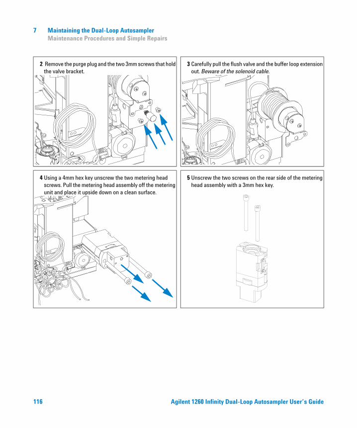
7 Maintaining the Dual-Loop Autosampler Maintenance Procedures and Simple Repairs
2 Remove the purge plug and the two 3mm screws that hold the valve bracket.
3 Carefully pull the flush valve and the buffer loop extension out. Beware of the solenoid cable.
4 Using a 4mm hex key unscrew the two metering head screws. Pull the metering head assembly off the metering unit and place it upside down on a clean surface.
5 Unscrew the two screws on the rear side of the metering head assembly with a 3mm hex key.
116 Agilent 1260 Infinity Dual-Loop Autosampler User’s Guide
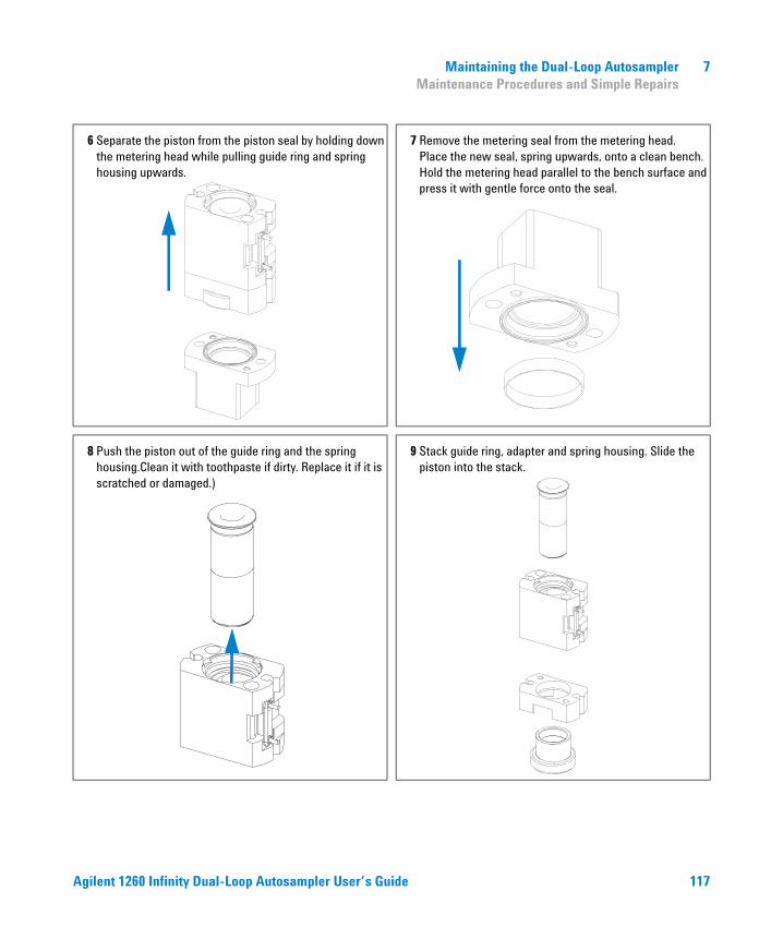
Maintaining the Dual-Loop Autosampler 7 Maintenance Procedures and Simple Repairs
6 Separate the piston from the piston seal by holding down the metering head while pulling guide ring and spring housing upwards.
7 Remove the metering seal from the metering head. Place the new seal, spring upwards, onto a clean bench. Hold the metering head parallel to the bench surface and press it with gentle force onto the seal.
8 Push the piston out of the guide ring and the spring housing.Clean it with toothpaste if dirty. Replace it if it is scratched or damaged.)
9 Stack guide ring, adapter and spring housing. Slide the piston into the stack.
Agilent 1260 Infinity Dual-Loop Autosampler User’s Guide 117
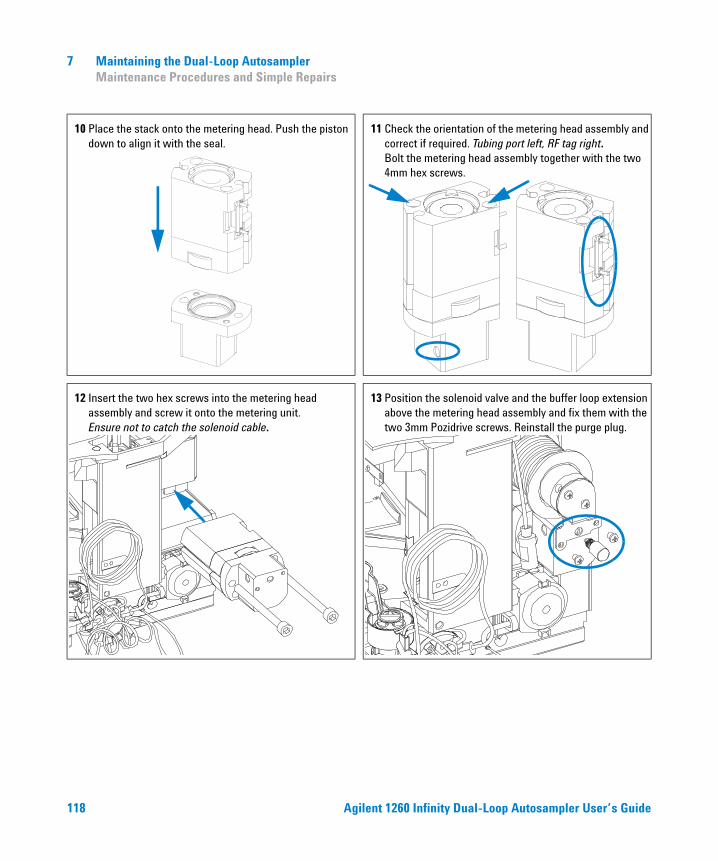
7 Maintaining the Dual-Loop Autosampler Maintenance Procedures and Simple Repairs
10 Place the stack onto the metering head. Push the piston down to align it with the seal.
11 Check the orientation of the metering head assembly and correct if required. Tubing port left, RF tag right. Bolt the metering head assembly together with the two 4mm hex screws.
12 Insert the two hex screws into the metering head assembly and screw it onto the metering unit. Ensure not to catch the solenoid cable.
13 Position the solenoid valve and the buffer loop extension above the metering head assembly and fix them with the two 3mm Pozidrive screws. Reinstall the purge plug.
118 Agilent 1260 Infinity Dual-Loop Autosampler User’s Guide
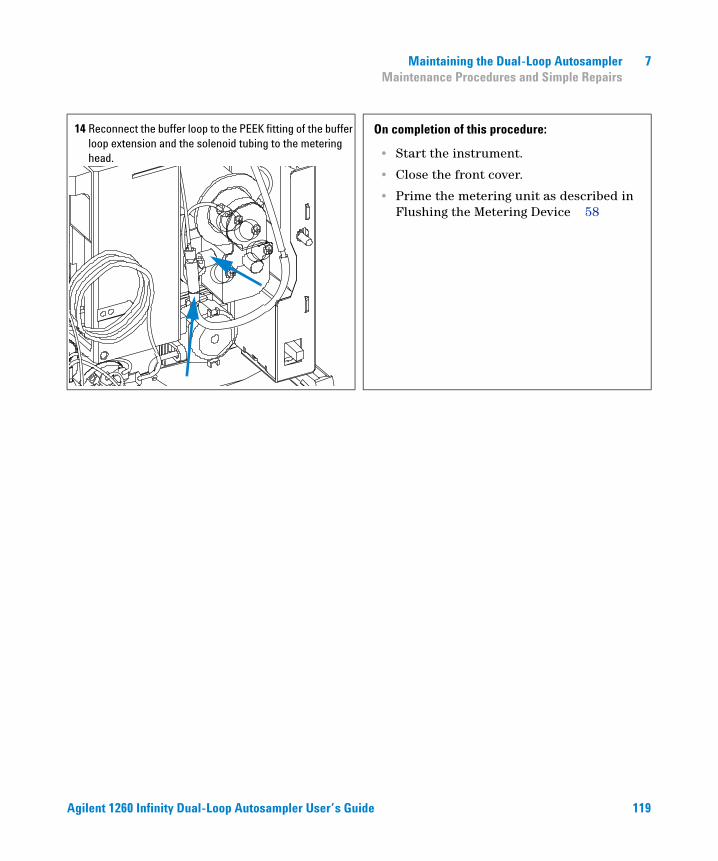
Maintaining the Dual-Loop Autosampler 7 Maintenance Procedures and Simple Repairs
14 Reconnect the buffer loop to the PEEK fitting of the buffer loop extension and the solenoid tubing to the metering head.
On completion of this procedure:
• Start the instrument.
• Close the front cover.
• Prime the metering unit as described in Flushing the Metering Device 58
Agilent 1260 Infinity Dual-Loop Autosampler User’s Guide 119
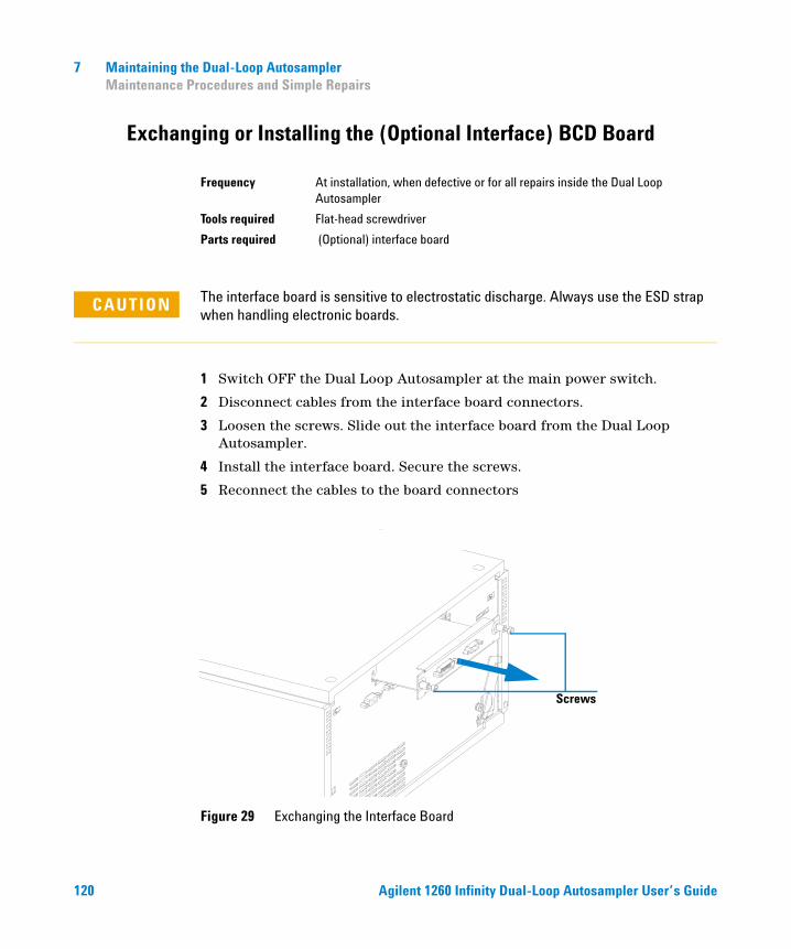
7 Maintaining the Dual-Loop Autosampler Maintenance Procedures and Simple Repairs
Exchanging or Installing the (Optional Interface) BCD Board
1 Switch OFF the Dual Loop Autosampler at the main power switch.
2 Disconnect cables from the interface board connectors.
3 Loosen the screws. Slide out the interface board from the Dual Loop Autosampler.
4 Install the interface board. Secure the screws.
5 Reconnect the cables to the board connectors
Frequency At installation, when defective or for all repairs inside the Dual Loop Autosampler
Tools required Flat-head screwdriver
Parts required (Optional) interface board
CAUTION The interface board is sensitive to electrostatic discharge. Always use the ESD strap when handling electronic boards.
Figure 29 Exchanging the Interface Board
Screws
120 Agilent 1260 Infinity Dual-Loop Autosampler User’s Guide
Agilent 1260 Infinity Dual-Loop AutosamplerUser’s Guide
8Easy Repair Parts
Consumables 122
List of Supported Plate Trays 122
List of Recommended Well Plates and Vial Plates 123
List of Recommended Vials, Caps and Septa 124
Sample Loops for the G2258A 10-port Valve 125
Dual-Loop Autosampler Accessory Kit 126
This chapter describes the Consumables and Accessories of the Dual Loop Autosampler.
121Agilent Technologies
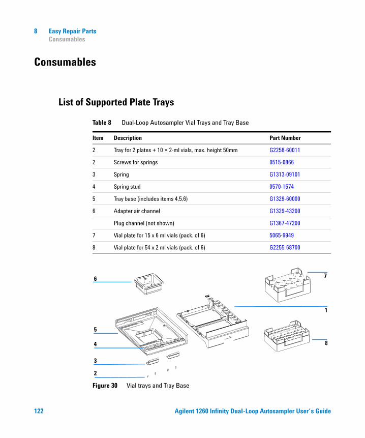
8 Easy Repair Parts Consumables
Consumables
List of Supported Plate Trays
Table 8 Dual-Loop Autosampler Vial Trays and Tray Base
Item Description Part Number
2 Tray for 2 plates + 10 × 2-ml vials, max. height 50mm G2258-60011
2 Screws for springs 0515-0866
3 Spring G1313-09101
4 Spring stud 0570-1574
5 Tray base (includes items 4,5,6) G1329-60000
6 Adapter air channel G1329-43200
Plug channel (not shown) G1367-47200
7 Vial plate for 15 x 6 ml vials (pack. of 6) 5065-9949
8 Vial plate for 54 x 2 ml vials (pack. of 6) G2255-68700
Figure 30 Vial trays and Tray Base
2
3
4
5
6
1
7
8
122 Agilent 1260 Infinity Dual-Loop Autosampler User’s Guide
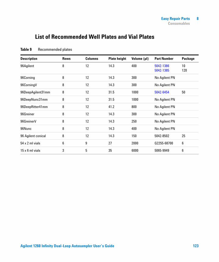
Easy Repair Parts 8 Consumables
List of Recommended Well Plates and Vial Plates
Table 9 Recommended plates
Description Rows Columns Plate height Volume (µI) Part Number Package
96Agilent 8 12 14.3 400 5042-13865042-1385
10120
96Corning 8 12 14.3 300 No Agilent PN
96CorningV 8 12 14.3 300 No Agilent PN
96DeepAgilent31mm 8 12 31.5 1000 5042-6454 50
96DeepNunc31mm 8 12 31.5 1000 No Agilent PN
96DeepRitter41mm 8 12 41.2 800 No Agilent PN
96Greiner 8 12 14.3 300 No Agilent PN
96GreinerV 8 12 14.3 250 No Agilent PN
96Nunc 8 12 14.3 400 No Agilent PN
96 Agilent conical 8 12 14.3 150 5042-8502 25
54 x 2 ml vials 6 9 27 2000 G2255-68700 6
15 x 6 ml vials 3 5 35 6000 5065-9949 6
Agilent 1260 Infinity Dual-Loop Autosampler User’s Guide 123
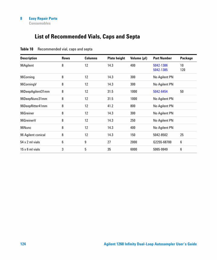
8 Easy Repair Parts Consumables
List of Recommended Vials, Caps and Septa
Table 10 Recommended vial, caps and septa
Description Rows Columns Plate height Volume (µI) Part Number Package
96Agilent 8 12 14.3 400 5042-13865042-1385
10120
96Corning 8 12 14.3 300 No Agilent PN
96CorningV 8 12 14.3 300 No Agilent PN
96DeepAgilent31mm 8 12 31.5 1000 5042-6454 50
96DeepNunc31mm 8 12 31.5 1000 No Agilent PN
96DeepRitter41mm 8 12 41.2 800 No Agilent PN
96Greiner 8 12 14.3 300 No Agilent PN
96GreinerV 8 12 14.3 250 No Agilent PN
96Nunc 8 12 14.3 400 No Agilent PN
96 Agilent conical 8 12 14.3 150 5042-8502 25
54 x 2 ml vials 6 9 27 2000 G2255-68700 6
15 x 6 ml vials 3 5 35 6000 5065-9949 6
124 Agilent 1260 Infinity Dual-Loop Autosampler User’s Guide
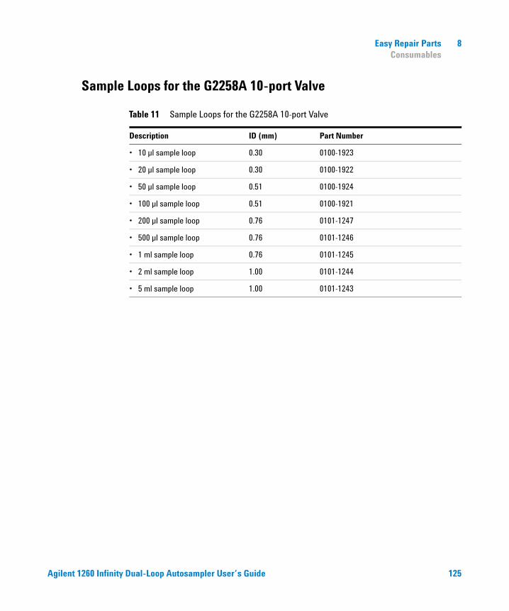
Easy Repair Parts 8 Consumables
Sample Loops for the G2258A 10-port Valve
Table 11 Sample Loops for the G2258A 10-port Valve
Description ID (mm) Part Number
• 10 µl sample loop 0.30 0100-1923
• 20 µl sample loop 0.30 0100-1922
• 50 µl sample loop 0.51 0100-1924
• 100 µl sample loop 0.51 0100-1921
• 200 µl sample loop 0.76 0101-1247
• 500 µl sample loop 0.76 0101-1246
• 1 ml sample loop 0.76 0101-1245
• 2 ml sample loop 1.00 0101-1244
• 5 ml sample loop 1.00 0101-1243
Agilent 1260 Infinity Dual-Loop Autosampler User’s Guide 125
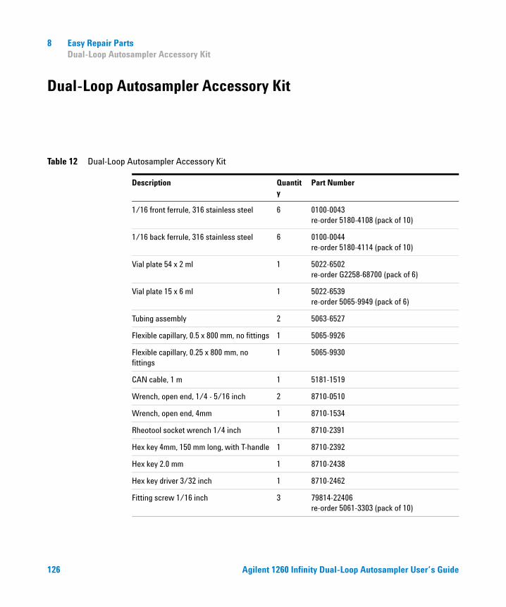
8 Easy Repair Parts Dual-Loop Autosampler Accessory Kit
Dual-Loop Autosampler Accessory Kit
Table 12 Dual-Loop Autosampler Accessory Kit
Description Quantity
Part Number
1/16 front ferrule, 316 stainless steel 6 0100-0043 re-order 5180-4108 (pack of 10)
1/16 back ferrule, 316 stainless steel 6 0100-0044 re-order 5180-4114 (pack of 10)
Vial plate 54 x 2 ml 1 5022-6502 re-order G2258-68700 (pack of 6)
Vial plate 15 x 6 ml 1 5022-6539re-order 5065-9949 (pack of 6)
Tubing assembly 2 5063-6527
Flexible capillary, 0.5 x 800 mm, no fittings 1 5065-9926
Flexible capillary, 0.25 x 800 mm, no fittings
1 5065-9930
CAN cable, 1 m 1 5181-1519
Wrench, open end, 1/4 - 5/16 inch 2 8710-0510
Wrench, open end, 4mm 1 8710-1534
Rheotool socket wrench 1/4 inch 1 8710-2391
Hex key 4mm, 150 mm long, with T-handle 1 8710-2392
Hex key 2.0 mm 1 8710-2438
Hex key driver 3/32 inch 1 8710-2462
Fitting screw 1/16 inch 3 79814-22406 re-order 5061-3303 (pack of 10)
126 Agilent 1260 Infinity Dual-Loop Autosampler User’s Guide
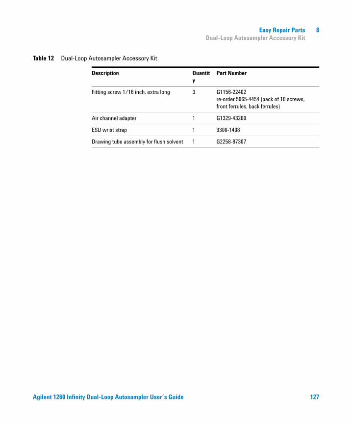
Easy Repair Parts 8 Dual-Loop Autosampler Accessory Kit
Fitting screw 1/16 inch, extra long 3 G1156-22402 re-order 5065-4454 (pack of 10 screws, front ferrules, back ferrules)
Air channel adapter 1 G1329-43200
ESD wrist strap 1 9300-1408
Drawing tube assembly for flush solvent 1 G2258-87307
Table 12 Dual-Loop Autosampler Accessory Kit
Description Quantity
Part Number
Agilent 1260 Infinity Dual-Loop Autosampler User’s Guide 127

8 Easy Repair Parts Dual-Loop Autosampler Accessory Kit
128 Agilent 1260 Infinity Dual-Loop Autosampler User’s Guide
Agilent 1260 Infinity Dual-Loop AutosamplerUser’s Guide
ASafety Information
Safety Information 130
Lithium Batteries Information 133
Radio Interference 134
Sound Emission 135
Solvent Information 136
Agilent Technologies on Internet 137
This chapter gives Safety Information for the use of the Dual Loop Autosampler.
129Agilent Technologies
A Safety Information Safety Information
Safety Information
The following general safety precautions must be observed during all phases of operation, service, and repair of this instrument. Failure to comply with these precautions or with specific warnings elsewhere in this manual violates safety standards of design, manufacture, and intended use of the instrument. Agilent Technologies assumes no liability for the customer’s failure to comply with these requirements.
General
This is a Safety Class I instrument (provided with terminal for protective earthing) and has been manufactured and tested according to international safety standards.
WARNING If you are using flammable solvents, remove the well-plates from the tray when you turn OFF the sampler. You avoid the risk of building explosive gas mixtures in the tray compartment.
WARNING If you are using flammable solvents, cover the well-plates with pre-slit closing mats to avoid the risk of building explosive gas mixtures.
WARNING After a leak in the sampler, make sure the leak plane is cleaned and dry.
130 Agilent 1260 Infinity Dual-Loop Autosampler User’s Guide
Safety Information A Safety Information
Operation
Before applying power, comply with the installation section. Additionally the following must be observed.
Do not remove instrument covers when operating. Before the instrument is switched on, all protective earth terminals, extension cords, auto-transformers, and devices connected to it must be connected to a protective earth via a ground socket. Any interruption of the protective earth grounding will cause a potential shock hazard that could result in serious personal injury. Whenever it is likely that the protection has been impaired, the instrument must be made inoperative and be secured against any intended operation.
Make sure that only fuses with the required rated current and of the specified type (normal blow, time delay, and so on) are used for replacement. The use of repaired fuses and shorting of fuse holders must be avoided.
Do not operate the instrument in the presence of flammable gases or fumes. Operation of any electrical instrument in such an environment constitutes a definite safety hazard.
Do not install substitute parts or make any unauthorized modification to the instrument.
Capacitors inside the instrument may still be charged, even though the instrument has been disconnected from its source of supply. Dangerous voltages, capable of causing serious personal injury, are present in this instrument. Use extreme caution when handling, testing and adjusting.
WARNING Any adjustment, maintenance, and repair of the opened instrument under voltage is forbidden.
WARNING Disconnect the instrument from the line and unplug the power cord before maintenance.
Agilent 1260 Infinity Dual-Loop Autosampler User’s Guide 131
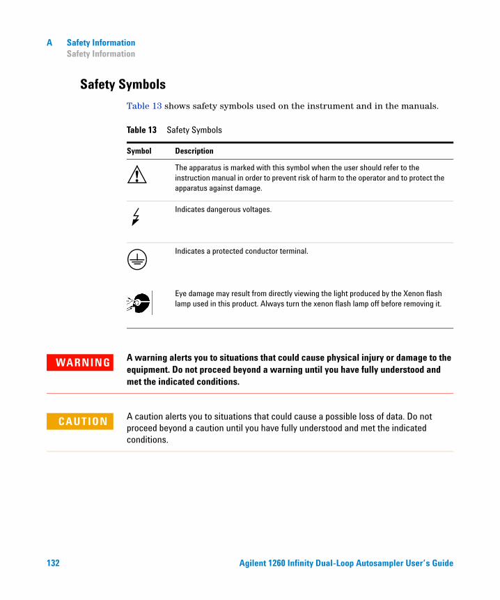
A Safety Information Safety Information
Safety Symbols
Table 13 shows safety symbols used on the instrument and in the manuals.
Table 13 Safety Symbols
Symbol Description
The apparatus is marked with this symbol when the user should refer to the instruction manual in order to prevent risk of harm to the operator and to protect the apparatus against damage.
Indicates dangerous voltages.
Indicates a protected conductor terminal.
Eye damage may result from directly viewing the light produced by the Xenon flash lamp used in this product. Always turn the xenon flash lamp off before removing it.
!
WARNING A warning alerts you to situations that could cause physical injury or damage to the equipment. Do not proceed beyond a warning until you have fully understood and met the indicated conditions.
CAUTION A caution alerts you to situations that could cause a possible loss of data. Do not proceed beyond a caution until you have fully understood and met the indicated conditions.
132 Agilent 1260 Infinity Dual-Loop Autosampler User’s Guide
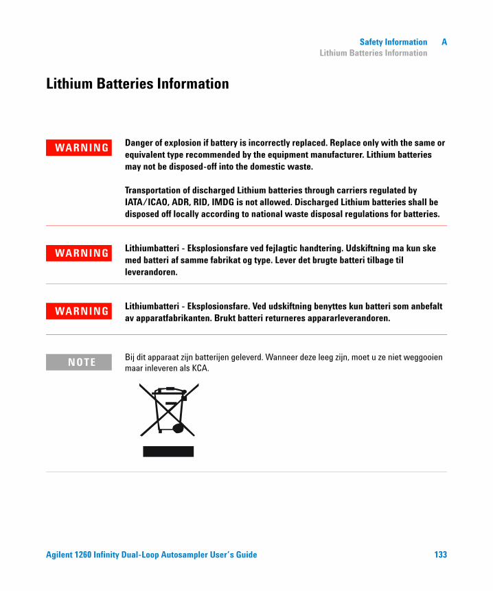
Safety Information A Lithium Batteries Information
Lithium Batteries Information
Bij dit apparaat zijn batterijen geleverd. Wanneer deze leeg zijn, moet u ze niet weggooien maar inleveren als KCA.
WARNING Danger of explosion if battery is incorrectly replaced. Replace only with the same or equivalent type recommended by the equipment manufacturer. Lithium batteries may not be disposed-off into the domestic waste. Transportation of discharged Lithium batteries through carriers regulated by IATA/ICAO, ADR, RID, IMDG is not allowed. Discharged Lithium batteries shall be disposed off locally according to national waste disposal regulations for batteries.
WARNING Lithiumbatteri - Eksplosionsfare ved fejlagtic handtering. Udskiftning ma kun ske med batteri af samme fabrikat og type. Lever det brugte batteri tilbage til leverandoren.
WARNING Lithiumbatteri - Eksplosionsfare. Ved udskiftning benyttes kun batteri som anbefalt av apparatfabrikanten. Brukt batteri returneres appararleverandoren.
NOTE
Agilent 1260 Infinity Dual-Loop Autosampler User’s Guide 133
A Safety Information Radio Interference
Radio Interference
Never use cables other than the ones supplied by Agilent Technologies to ensure proper functionality and compliance with safety or EMC regulations.
Test and Measurement
If test and measurement equipment is operated with equipment unscreened cables and/or used for measurements on open set-ups, the user has to assure that under operating conditions the radio interference limits are still met within the premises.
134 Agilent 1260 Infinity Dual-Loop Autosampler User’s Guide
Safety Information A Sound Emission
Sound Emission
Manufacturer’s Declaration
This statement is provided to comply with the requirements of the German Sound Emission Directive of 18 January 1991.
This product has a sound pressure emission (at the operator position) < 70 dB.
• Sound Pressure Lp < 70 dB (A)
• At Operator Position
• Normal Operation
• According to ISO 7779:1988/EN 27779/1991 (Type Test)
Agilent 1260 Infinity Dual-Loop Autosampler User’s Guide 135
A Safety Information Solvent Information
Solvent Information
Observe the following recommendations on the use of solvents.
Solvents
Brown glass ware can avoid growth of algae.
Always filter solvents, small particles can permanently block the capillaries. Avoid the use of the following steel-corrosive solvents:
• Solutions of alkali halides and their respective acids (for example, lithium iodide, potassium chloride, and so on).
• High concentrations of inorganic acids like nitric acid, sulfuric acid especially at higher temperatures (replace, if your chromatography method allows, by phosphoric acid or phosphate buffer which are less corrosive against stainless steel).
• Halogenated solvents or mixtures which form radicals and/or acids, for example:
2CHCl3 + O2 → 2COCl2 + 2HCl
This reaction, in which stainless steel probably acts as a catalyst, occurs quickly with dried chloroform if the drying process removes the stabilizing alcohol.
• Chromatographic grade ethers, which can contain peroxides (for example, THF, dioxane, di-isopropylether) such ethers should be filtered through dry aluminium oxide which adsorbs the peroxides.
• Solutions of organic acids (acetic acid, formic acid, and so on) in organic solvents. For example, a 1-% solution of acetic acid in methanol will attack steel.
WARNING This instrument should only be used with solvents that have an ignition temperature higher than 200oC!
136 Agilent 1260 Infinity Dual-Loop Autosampler User’s Guide
Safety Information A Agilent Technologies on Internet
• Solutions containing strong complex forming agents (for example, EDTA, ethylene diamine tetra-acetic acid).
• Mixtures of carbon tetrachloride with 2-propanol or THF.
Agilent Technologies on Internet
For the latest information on products and services visit our worldwide web site on the Internet at:
http://www.agilent.com
Select “Products” - “Chemical Analysis”
It will provide also the latest firmware of the Agilent 1260 Infinity modules for download.
Agilent 1260 Infinity Dual-Loop Autosampler User’s Guide 137

A Safety Information Agilent Technologies on Internet
138 Agilent 1260 Infinity Dual-Loop Autosampler User’s Guide
Index
Aaccessory kit contents, 41Agilent on internet, 137air circulation, 31
Bbattery
safety information, 133BCD board, 120bench space, 31
Ccable
connecting APG remote, 44, 46connecting CAN, 44, 46connecting GPIB, 44, 46connecting LAN, 44, 46connecting the ChemStation, 44, 46connecting the power, 44, 46
cable connections, 53capillaries, 55capillary guiding assembly
exchange, 110capillary tip alignment, 102, 103, 106, 107cleaning the fraction collector, 93collection order, 73condensation, 32configuration
collection order, 73trays, 70
Ddamaged packaging, 38delivery checklist, 38
Eelectrical connections
thermostat, 54environment, 30, 32, 38error messages, 86
Ffailure, 86flow connections, 55fuses, 30
Iinlet / waste tubings, 97installing the autosampler, 47
interface cables, 47power cable, 47safety, 47
installing the fraction collector, 47flow connections, 55interface cables, 47power cable, 47safety, 47
installing the thermostatted autosamplerinterface cables, 50power cable, 50preparation, 50safety, 47, 50
installing the thermostatted fraction collector
interface cables, 53power cable, 53safety, 47, 53
instrument status indicator, 89internet, 137
Mmaintenance functions, 86missing parts, 38
Nneedle, 104needle-carrier assembly, 112
Ppark transport unit assembly, 68
parts and materials, 38, 121accessory kit, 126vial trays and tray base, 122
performance specificationspreparative scale, 34
physical specifications, 32fraction collector, 32thermostat, 33
power consideration, 30power cords, 31power requirements, 30power supply indicator, 88preparative needle assembly, 104Push, 103, 106, 107push, 102
Rrepairing the fraction collector, 91, 95repairs
BCD board, 120cleaning the fraction collector, 93inlet / waste tubings, 97needle, 104needle-carrier assembly, 112preparative needle assembly, 104simple repairs, 92, 96valve to needle tubings, 100
Ssafety information
on lithium batteries, 133shipping, 68simple repairs, 92, 96site requirements, 30, 38specifications, 32stack configuration, 44, 46
rear view, 44, 46status indicators, 86, 88storage, 32
Ttemperature, 32
Agilent 1260 Infinity Dual-Loop Autosampler User’s Guide 139

Index
thermostatelectrical connections, 54
transport, 68transport unit assembly, 68transport unit self alignment, 86transporting the fraction collector, 68trays, 70troubleshooting and test functions, 85
Uunpacking the fraction collector, 38
Vvalve to needle tubings, 100
Wweight, 31
140 Agilent 1260 Infinity Dual-Loop Autosampler User’s Guide

© Agilent Technologies 2010Printed in Germany 06/10
*G2258-90012**G2258-90012*G2258-90012
www.agilent.com
Agilent Technologies
In This Book
This manual contains technical reference information about the Agilent 1260 Infinity Dual-Loop Autosamplers. The manual describes the following:
• Introduction to the Dual-Loop Autosampler,
• site requirements, specifications and installation,
• configuration and operation of the Dual-Loop Autosampler,
• troubleshooting and test functions,
• maintaining the Dual-Loop Autosampler,
• parts for maintenenance,
• safety information.