afcs enterprise controller - skf
TRANSCRIPT
User and maintenance instructions
Model 343530
AFCS Enterprise controller
Date of issue August 2021
Form number 671097
Version 3
Contents
Explanation of safety signals 2
Safety 3
Introduction 3
Controller overview 5
Mounting dimensions 6
Cat 5 ethernet network wiring 13
Wiring diagram 14
Configure controller 14
Tank monitor functions 19
AFCS Enterprise controller parts/kits 19
Troubleshooting 20
Warranty 24
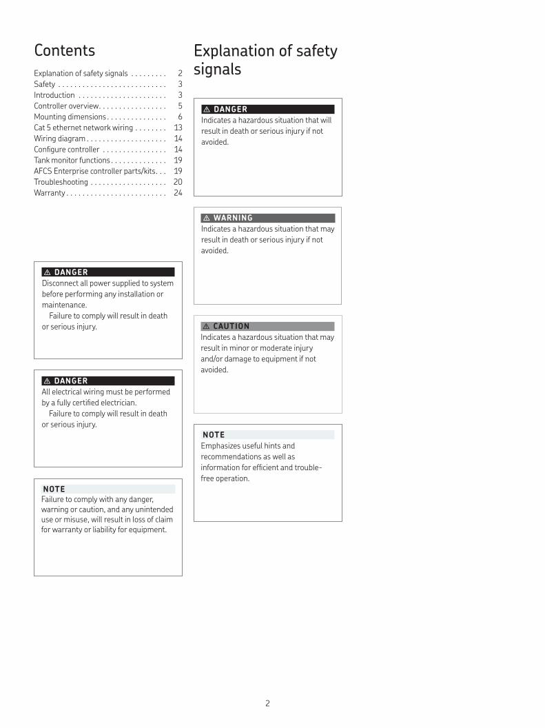
Explanation of safety signals
� CAUTION
Indicates a hazardous situation that may
result in minor or moderate injury
and/or damage to equipment if not
avoided
� WARNING
Indicates a hazardous situation that may
result in death or serious injury if not
avoided
� DANGER
Indicates a hazardous situation that will
result in death or serious injury if not
avoided
NOTE
Failure to comply with any danger, warning or caution, and any unintended use or misuse, will result in loss of claim for warranty or liability for equipment
� DANGER
Disconnect all power supplied to system
before performing any installation or
maintenance
Failure to comply will result in death
or serious injury
� DANGER
All electrical wiring must be performed
by a fully certified electrician
Failure to comply will result in death
or serious injury
NOTE
Emphasizes useful hints and
recommendations as well as
information for efficient and trouble-
free operation
2

Safety
Read and carefully observe installation
instructions before installing, operating or
troubleshooting referenced equipment
Equipment must be installed, maintained
and repaired exclusively by persons familiar
with instructions
While unpacking, verify unit is complete
and free from any damage Install unit with
power supply cords and wiring secured away
from vehicle and other types of contact
Do not place unit near or over radiator or
heat register Verify unit is properly grounded
AFCS Enterprise controller must be
equipped with plug having third (grounding)
pin fitting only into grounding type outlet
Remove power from controller unit before
attempting to clean or decontaminate
External cleaning can be done with moist
towel Use compressed air to remove dust
or other contaminants from inside
enclosure
NOTE
Do not use AFCS Enterprise controller
without properly grounded outlet
Failure to properly ground controller
may cause damage to unit or data
stored
NOTE
Place locking device on eyelet of enclo-sure to prevent unauthorized users from accessing controller
Introduction
AFCS Enterprise controller model 343530
controller integrates with other AFCS
Enterprise components over system
network, allowing precise control and
tracking of oil dispense points
Network configuration is performed
directly through LCD touchscreen interface
This guide provides mounting, wiring and
configuring instructions and other helpful
information for AFCS Enterprise controller
model 343530 installation and maintenance
Product specification
Temperature range 32 to 122 °F (0 to 50 °C)Net weight 5 25 lbs (2,38 kg)Input voltage 100-240 V AC, 50-60 Hz
Minimum current 0 1 AMaximum current 4 5 APulse switch voltage 24 V
Pulse switch current 30 mAAnalog input voltage range 0-10 VAnalog input current range 0-20 mA
Valve output voltage 24 V Maximum valve output current 1 85 AFuse 250V 6A medium-acting
glass/ceramic 5 x 20mm1)
Altitude Up to 2000 mHumidity Maximum RH 80% for temperatures
up to 31 °C decreasing to 50% RH at 40 °CTransient over-voltage Category II
Mains supply voltage +/-10% of nominal voltage
Table 1
� WARNING
Only use product under conditions
specified in document
Failure to comply may result in death
or serious personal injury
NOTE
Install socket-outlet near equipment in
a place that is easily accessible Mains
plug is disconnect device
� WARNING
For indoor use only
Failure to comply may result in
serious personal injury and/or damage
to equipment
1) Reference: Littelfuse 0234006MXP
NOTE
Unplug controller from AC Voltage source before servicing fuse Verify fuse holder is fully inserted before plugging controller back into AC voltage source
3

Fig. 1
AFCS Enterprise network
Fig. 2
AFCS Enterprise Hardware
2
3
4
1
5
6
7
8
9
1
2 3
5 6
6
7 8 9
54
3
2
C
BA
4
Item Description
1 AFCS Enterprise web server2 AFCS Enterprise database3 Oil tank
4 Pump5 Tank level sensor6 AFCS controller
7 Combo unit8 Hose reel9 PC/web browser
Item Description
A System line with wall-mounted pump
B System line with tank-mounted pump
C Line to hose reels
1 Check valve2 Pump (wall or pump
mounted)3 Air supply
4 Tank return line located below check valve
5 Pressure relief valve6 Shut off valve
7 Filter8 Fluid solendoid9 Pulse meter
4
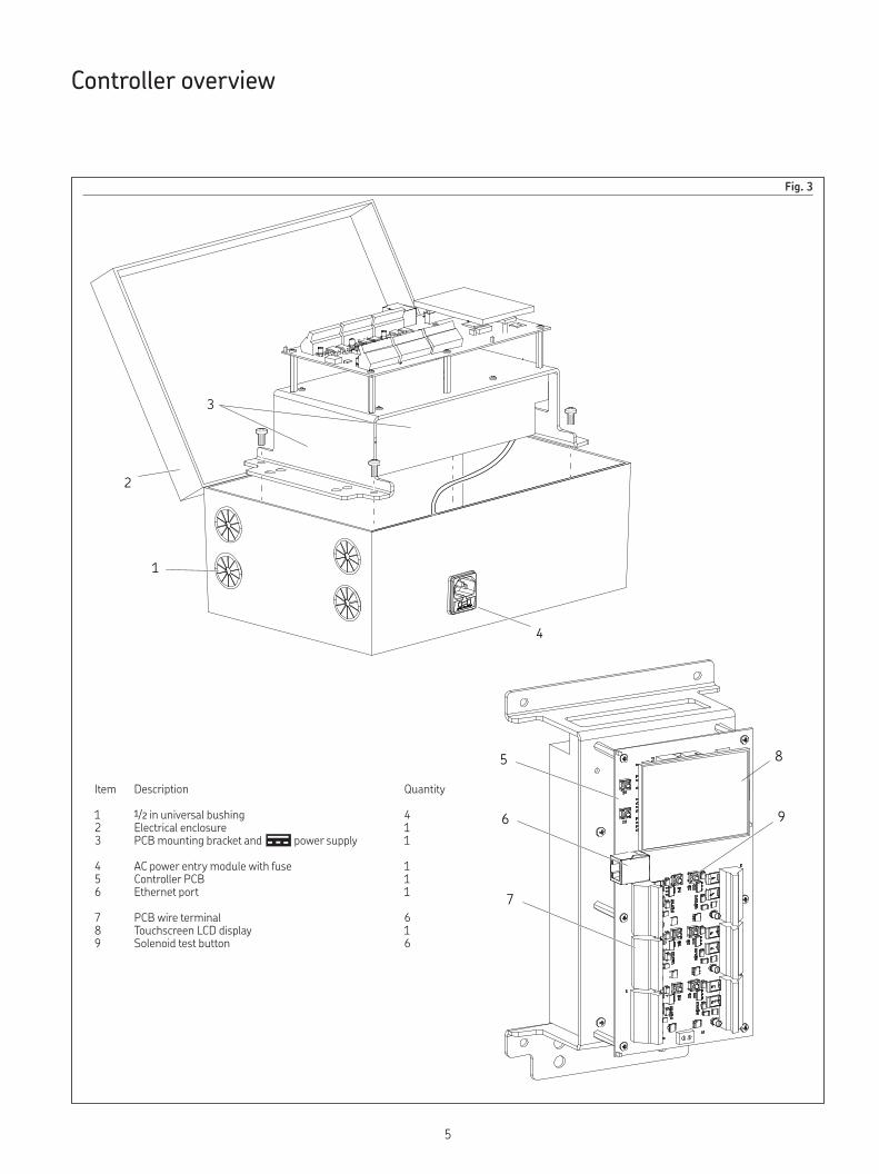
Fig. 3
Controller overview
1
2
3
4
8
6
5
7
9
Item Description Quantity
1 1/2 in universal bushing 42 Electrical enclosure 13 PCB mounting bracket and power supply 1
4 AC power entry module with fuse 15 Controller PCB 16 Ethernet port 1
7 PCB wire terminal 68 Touchscreen LCD display 19 Solenoid test button 6
5
1.22 in
(31 mm)
Ø.185 in
(4,7 mm)
Ø.287 in
(7,3 mm)
1.22 in
(31 mm)
7.24 in
(183,8 mm)
6.06 in
(154 mm)
11.23 in
(285,3 mm)
0.61 in
(15,4 mm)
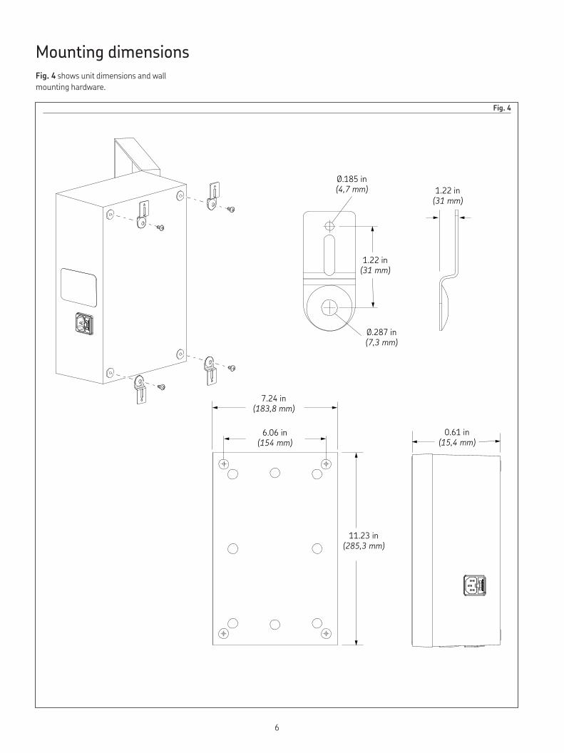
Mounting dimensions
Fig. 4 shows unit dimensions and wall
mounting hardware
Fig. 4
6
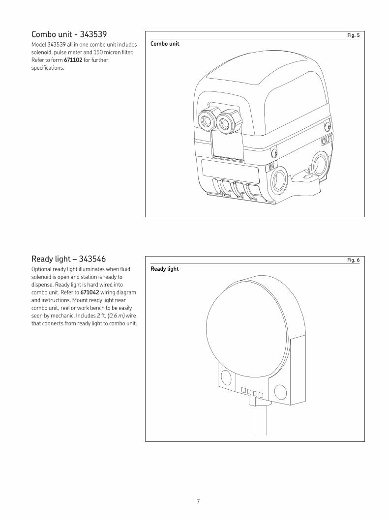
Combo unit - 343539Model 343539 all in one combo unit includes
solenoid, pulse meter and 150 micron filter
Refer to form 671102 for further
specifications
Ready light – 343546Optional ready light illuminates when fluid
solenoid is open and station is ready to
dispense Ready light is hard wired into
combo unit Refer to 671042 wiring diagram
and instructions Mount ready light near
combo unit, reel or work bench to be easily
seen by mechanic Includes 2 ft (0,6 m) wire
that connects from ready light to combo unit
Fig. 5
Fig. 6
Combo unit
Ready light
7
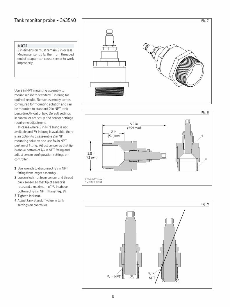
Tank monitor probe - 343540 Fig. 7
Fig. 8
5.9 in(150 mm)
2 in(51 )mm
2.8 in(71 mm)
1)
2)
NOTE
2 in dimension must remain 2 in or less Moving sensor tip further from threaded end of adapter can cause sensor to work improperly
1) 3/4 in NPT thread2) 2 in NPT thread
Use 2 in NPT mounting assembly to
mount sensor to standard 2 in bung for
optimal results Sensor assembly comes
configured for mounting solution and can
be mounted to standard 2 in NPT tank
bung directly out of box Default settings
in controller are setup and sensor settings
require no adjustment
In cases where 2 in NPT bung is not
available and 3/4 in bung is available, there
is an option to disassemble 2 in NPT
mounting solution and use 3/4 in NPT
portion of fitting Adjust sensor so that tip
is above bottom of 3/4 in NPT fitting and
adjust sensor configuration settings on
controller
1 Use wrench to disconnect 3/4 in NPT
fitting from larger assembly
2 Loosen lock nut from sensor and thread
back sensor so that tip of sensor is
recessed a maximum of 1/2 in above
bottom of 3/4 in NPT fitting (Fig. 9)
3 Tighten lock nut
4 Adjust tank standoff value in tank
settings on controller
34 /
/
/ in NPT 12
12
34/ in
NPT
Fig. 9
8

Fig. 10
A
A A A
B B B
B C
D
D D D
E E E
Fig. 10 shows if fluid level is at or above
blind zone, tank monitor system will read it
as 100% full
A - Fluid level in tank
B - Blind zone for ultrasonic sensor -
All non-contact ultrasonic sensors have
an area close to the sensor that is
unable to be measured, known as the
blind zone
C - Tank standoff value
D - Maximum fluid level sensor can read
E - Tank monitor reading
NOTE
Sensor range: 86 in (2 200 mm) to 8 in (200 mm) from tip of sensor
9
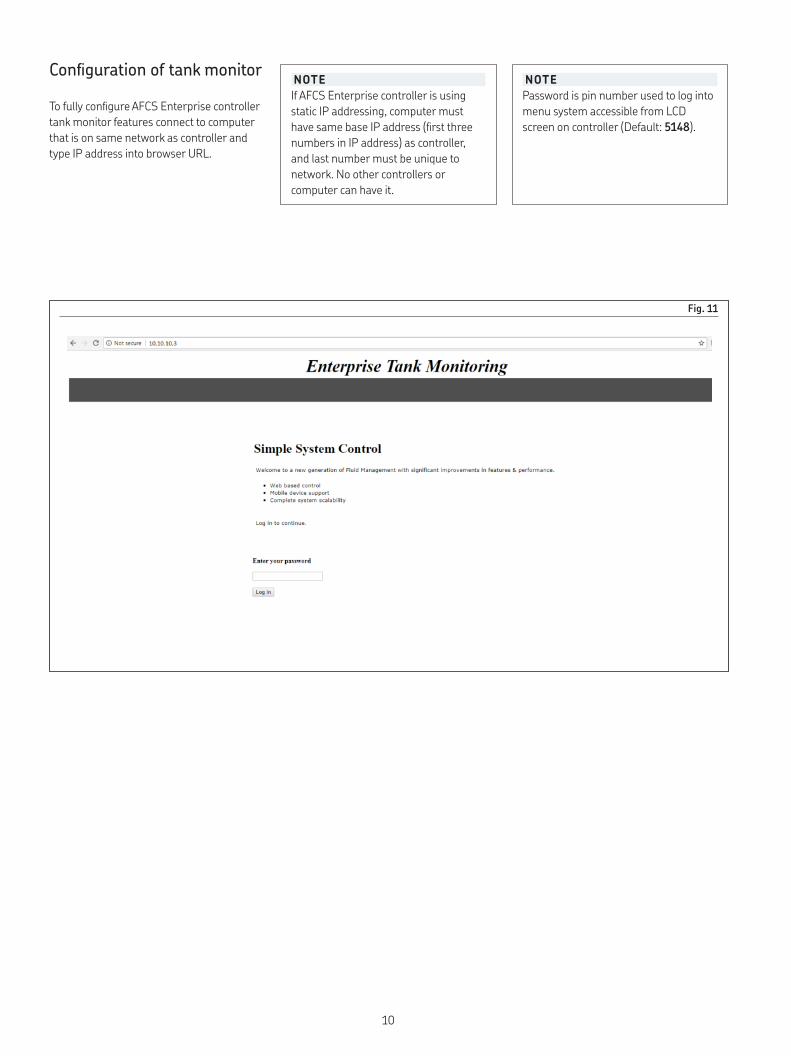
Configuration of tank monitor
To fully configure AFCS Enterprise controller
tank monitor features connect to computer
that is on same network as controller and
type IP address into browser URL
Fig. 11
NOTE
If AFCS Enterprise controller is using
static IP addressing, computer must
have same base IP address (first three
numbers in IP address) as controller,
and last number must be unique to
network No other controllers or
computer can have it
NOTE
Password is pin number used to log into
menu system accessible from LCD
screen on controller (Default: 5148)
10
For configuration options, go to Configure
tab on navigation banner at top of page
Select tank to configure Configure tanks
individually or all the same Refer to Fig. 12,
page 12
• Save changes
• Tank Dimensions - Only required tank
dimensions for given tank shape will be
displayed for entry Please reference tank
shape diagram to find the fields
corresponding to values
• Sensor Maximum Range - Sensor
maximum range and inversion options are
for people not using Alemite tank monitor
sensor In this case, maximum range and
inversion option for sensor being used
must be entered here
NOTE
Do not forget to save changes before
leaving configuration screen If you leave
screen without saving, configuration
parameters will be lost
• Enable Monitoring - Enables or disables
tank monitor for chosen port Only
enabled ports will have results displayed
in Monitor tab and Enterprise software
• Fluid Type - New Fluids and Used Fluids
have different warning levels because new
fluid tanks are being emptied by pumps
and used fluid tanks are being
filled by pumps
• Tank Volume Units - Tank volume units
can be measured in Gallons and Liters
• Tank Dimension Units - Units used when
configuring tank dimensions Available
options are Inches, Feet, Millimeters and
Meters
• Tank Shape - Shape of tank is important
to calculate volume of tank Choose tank
shape closest to tank If tank that is desired
to be monitored has an irregular shape,
irregular shape tank option can be
selected This presents option to fill in a
“look-up table” that corresponds a fluid
height to a percentage and volume
NOTE
Do not use Calibration Settings or
Advanced Features unless you have
been through AFCS Enterprise training
NOTE
Do not attempt to calibrate sensors
arbitrarily Calibrating sensors to be
more accurate than default values
require extreme precision
NOTE
Measurements should be taken from
inside of tank if tank has double wall
• Warning Level - Volume of initial warning
level that alerts user that tank level
needs attention
• Stop Level - Volume of stop level that will
prevent Enterprise software from allowing
further fluid dispensing from tank
• Sensor Standoff - Distance between tip
of fluid sensor and top of tank
• Maximum Fluid Height - Maximum
height of fluid in tank By default this is
assumed to be maximum height of tank as
entered in Tank Dimensions section
• Calibration Settings - Controller comes
with factory default calibration settings for
Tank Monitor probe kit Default settings
are accurate within 1/2 in If maximum
accuracy is needed, further calibration can
be accomplished on system by taking two
point measurement and entering precise
distances and raw analog value measured
by sensor Two point measurement
calibration procedure is available from
touchscreen menu and described in
further detail there
• Advanced Features
11
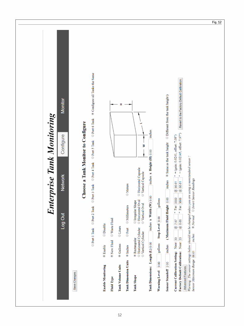
Fig. 12
12
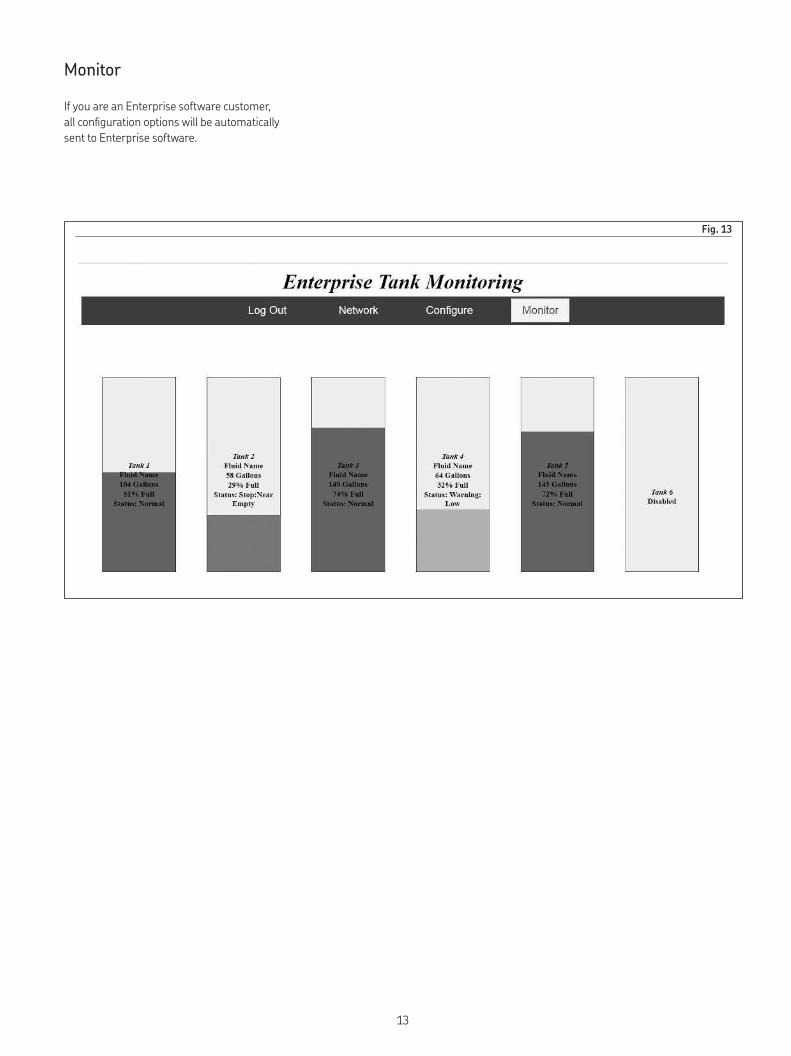
Fig. 13
Monitor
If you are an Enterprise software customer,
all configuration options will be automatically
sent to Enterprise software
13
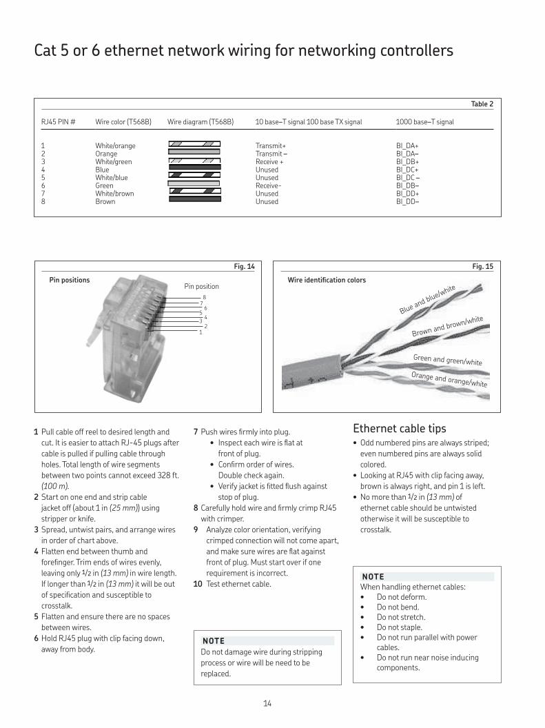
Cat 5 or 6 ethernet network wiring for networking controllers
1 Pull cable off reel to desired length and
cut It is easier to attach RJ-45 plugs after
cable is pulled if pulling cable through
holes Total length of wire segments
between two points cannot exceed 328 ft
(100 m).
2 Start on one end and strip cable
jacket off (about 1 in (25 mm)) using
stripper or knife
3 Spread, untwist pairs, and arrange wires
in order of chart above
4 Flatten end between thumb and
forefinger Trim ends of wires evenly,
leaving only 1/2 in (13 mm) in wire length
If longer than 1/2 in (13 mm) it will be out
of specification and susceptible to
crosstalk
5 Flatten and ensure there are no spaces
between wires
6 Hold RJ45 plug with clip facing down,
away from body
Blue and blue/white
Brown and b
rown/white
Green and green/white
Orange and orange/white
7 Push wires firmly into plug
• Inspect each wire is flat at
front of plug
• Confirm order of wires
Double check again
• Verify jacket is fitted flush against
stop of plug
8 Carefully hold wire and firmly crimp RJ45
with crimper
9 Analyze color orientation, verifying
crimped connection will not come apart,
and make sure wires are flat against
front of plug Must start over if one
requirement is incorrect
10 Test ethernet cable
Ethernet cable tips• Odd numbered pins are always striped;
even numbered pins are always solid
colored
• Looking at RJ45 with clip facing away,
brown is always right, and pin 1 is left
• No more than 1/2 in (13 mm) of
ethernet cable should be untwisted
otherwise it will be susceptible to
crosstalk
RJ45 PIN # Wire color (T568B) Wire diagram (T568B) 10 base–T signal 100 base TX signal 1000 base–T signal
1 White/orange Transmit+ BI_DA+2 Orange Transmit – BI_DA–3 White/green Receive + BI_DB+4 Blue Unused BI_DC+5 White/blue Unused BI_DC –6 Green Receive- BI_DB–7 White/brown Unused BI_DD+8 Brown Unused BI_DD–
Pin position
Fig. 14
Pin positions
Fig. 15
Wire identification colors
12
34
56
78
NOTE
Do not damage wire during stripping
process or wire will be need to be
replaced
NOTE
When handling ethernet cables:• Do not deform • Do not bend • Do not stretch • Do not staple • Do not run parallel with power
cables • Do not run near noise inducing
components
Table 2
14

Fig. 16
A
(+)
(-)
(+)
(-)
(+)
(-)
J
K
L
B
D
C
E F G
H
2 1
3 4
1243
(+)CEB(-)F
Wiring diagram
Fig. 16 shows wiring connections from
hardware to controller wiring terminals
Four conductor 18AWG shielded cable (A)
is recommended
Configure controller
Once controller wiring connections are
complete, assign each controller unique unit
number for each site and site number, then
configure each controller to network
• Assign unit number and site number
• Obtain MAC address This is based on unit
number and site number
• Assign IP mode (static or DHCP)
• Configure network settings (static
mode only)
� DANGER
Disconnect all power supplied to
controller before performing installation
or wiring
Failure to comply will result in death
or serious injury
Item Description Item Description
A Conductor 18 AWG shield cable (4) E Analog signal 343533-100 ft (30,48 m) F Blue wire 343533-250 ft (76,2 m) G Tank sensor 343533-500 ft (152,4 m)
B Black wire (not used) H Combo unit (refer to service page 671102)C Brown wire J Solenoid valve cable connection (+ and -)D White wire K Pulse switch cable connection (+ and -)
L Cable shield ground connection
NOTE
Do not exceed 200 ft (60,96 m) with
18 AWG cable when connecting solenoid
and pulse meters Individual cable
lengths should be 100 ft (30,48 m) or
less
NOTE
Apply power and configure controller
before connecting to network via
ethernet networking cable
NOTE
Assign each controller unique unit
number for each site
Unit and site numbers are used to
generate a unique MAC address for each
controller
15

1
4
7
DELETE
2
5
8
0
3
6
9
OKX
Enteryour
password
Unit Number 1 is online at 10.10.10.1
Full operating mode & communicating
1: Hose 1 10W40
Idle
1: Hose 1 10W40
Idle
1: Hose 1 10W40
Idle
1: Hose 1 10W40
Idle
1: Hose 1 10W40
Idle
1: Hose 1 10W40
Idle
1
4
7
DELETE
2
5
8
0
3
6
9
OKX
Enteryour
password
X
Currently in Normal Operating
Mode
(not override)
Switch to Override
(allows manual dispenses with no computer access)
Switch to Automatic (goes to override
when the network seems to be down)
X
PasswordTank Monitor
DHCP: OffIP Address
Site: 1Controller: 1
MAC Address00:50:C2:77:D1:01
1
4
7
DELETE
2
5
8
0
3
6
9
OKX
Enterthis
dispense unit’s
number(1-30)
This iscurrentlyunit #1
1
4
7
DELETE
2
5
8
0
3
6
9
OKX
Enterthis
dispense unit’ssite
number(1-30)
This iscurrentlysite #1
X
Switch to DHCP mode
Currently in Static IP mode
X
IP Address: 10.10.10.2
Subnet Mask: 255.255.255.0
Default Gateway: 10.10.10.200
MAC Address00:50:C2:77:D1:01
1
4
7
DELETE
2
5
8
0
3
6
9
OKX
Enterthenew
password
The currentpassword
Is:
1234
1
4
7
DELETE
2
5
8
0
3
6
9
OKX
Enterthe
defaultgatewayaddress
The currentdefault
gatewayaddress
Is:
10.10.10.200
1
4
7
DELETE
2
5
8
0
3
6
9
OKX
Enterthe
subnetmask
address
The currentsubnetmask
addressis:
255.255.255.0
1
4
7
DELETE
2
5
8
0
3
6
9
OKX
EntertheIP
address
The currentIP address
Is:
10.10.10.1
Fig. 17
16
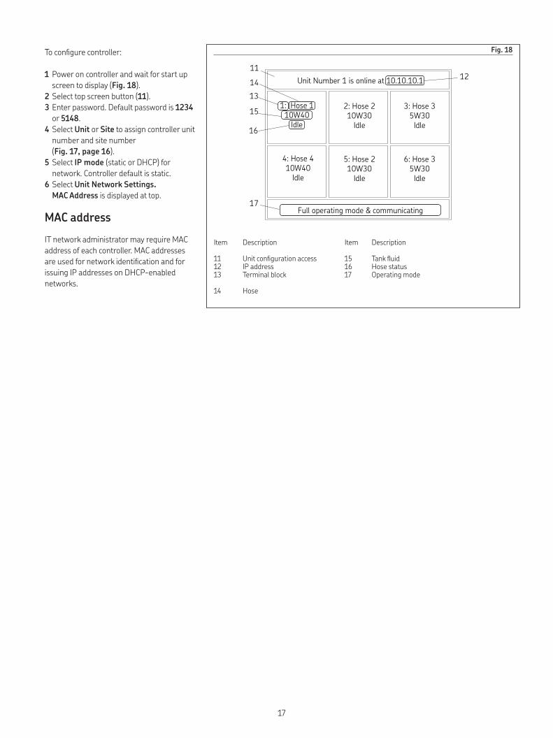
Fig. 18
Unit Number 1 is online at 10.10.10.1
1: Hose 1
10W40
Idle
2: Hose 2
10W30
Idle
5: Hose 2
10W30
Idle
3: Hose 3
5W30
Idle
6: Hose 3
5W30
Idle
4: Hose 4
10W40
Idle
Full operating mode & communicating
13
14
11
15
16
12
17
To configure controller:
1 Power on controller and wait for start up
screen to display (Fig. 18)
2 Select top screen button (11)
3 Enter password Default password is 1234
or 5148
4 Select Unit or Site to assign controller unit
number and site number
(Fig. 17, page 16)
5 Select IP mode (static or DHCP) for
network Controller default is static
6 Select Unit Network Settings.
MAC Address is displayed at top
MAC address
IT network administrator may require MAC
address of each controller MAC addresses
are used for network identification and for
issuing IP addresses on DHCP-enabled
networks
Item Description Item Description
11 Unit configuration access 15 Tank fluid12 IP address 16 Hose status13 Terminal block 17 Operating mode
14 Hose
17
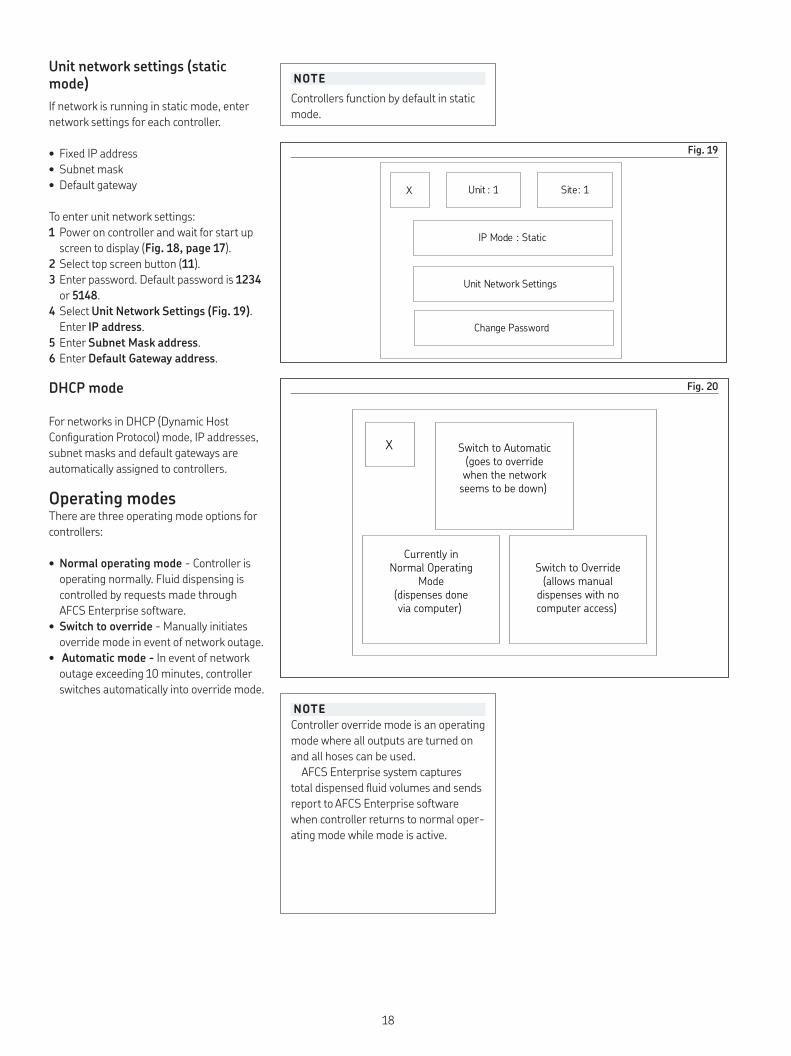
Unit network settings (static mode)
If network is running in static mode, enter
network settings for each controller
• Fixed IP address
• Subnet mask
• Default gateway
To enter unit network settings:
1 Power on controller and wait for start up
screen to display (Fig. 18, page 17)
2 Select top screen button (11)
3 Enter password Default password is 1234
or 5148
4 Select Unit Network Settings (Fig. 19)
Enter IP address
5 Enter Subnet Mask address
6 Enter Default Gateway address
DHCP mode
For networks in DHCP (Dynamic Host
Configuration Protocol) mode, IP addresses,
subnet masks and default gateways are
automatically assigned to controllers
Operating modesThere are three operating mode options for
controllers:
• Normal operating mode - Controller is
operating normally Fluid dispensing is
controlled by requests made through
AFCS Enterprise software
• Switch to override - Manually initiates
override mode in event of network outage
• Automatic mode - In event of network
outage exceeding 10 minutes, controller
switches automatically into override mode
Fig. 20
Fig. 19
X
Currently inNormal Operating
Mode(dispenses donevia computer)
Switch to Automatic(goes to overridewhen the networkseems to be down)
Switch to Override(allows manualdispenses with nocomputer access)
X Unit : 1 Site: 1
IP Mode : Static
Unit Network Settings
Change Password
NOTE
Controller override mode is an operating
mode where all outputs are turned on
and all hoses can be used
AFCS Enterprise system captures
total dispensed fluid volumes and sends
report to AFCS Enterprise software
when controller returns to normal oper-
ating mode while mode is active
NOTE
Controllers function by default in static
mode
18

Fig. 21
Tank monitor functions
Unit Number 1 is online at 10.10.10.1
Full operating mode & communicating
1: Hose 1 10W40
Idle
1: Hose 1 10W40
Idle
1: Hose 1 10W40
Idle
1: Hose 1 10W40
Idle
1: Hose 1 10W40
Idle
1: Hose 1 10W40
Idle
1
4
7
DELETE
2
5
8
0
3
6
9
OKX
Enteryour
password
X
PasswordTank Monitor
DHCP: OffIP Address
Site: 1Controller: 1
MAC Address00:50:C2:77:D1:01
X
Sensor Characteristics
Sensor StandoffCalibrate
Tank Monitor
X
Factory Default
Tank Sensor Testing & Calibration
Perform a Sensor Calibration
Display Live Sensor Readings
X Tank Sensor Calibration OK
If you change a sensor, a standoff tube , the controller or controller port it’s wired to, you must recalibrate . The sensor must be mounted in its standoff tube, standing upright on a hard flat surface beneath the tube, simulating a fluid level reaching the bottom of the tube. The green and yellow
sensor lights should be lit .
(1)Tank: #1
Fluid: Name
(2)Tank: #2
Fluid: Name
(3)Tank: #3
Fluid: Name
(4)Tank: #4
Fluid: Name
(5)Tank: #5
Fluid: Name
(6)Tank: #6
Fluid: Name
X Select the sensor to calibrate
(1)Tank: #1
Fluid: Name
(2)Tank: #2
Fluid: Name
(3)Tank: #3
Fluid: Name
(4)Tank: #4
Fluid: Name
(5)Tank: #5
Fluid: Name
(6)Tank: #6
Fluid: Name
XSelect a tank sensor to reset to
factory default calibration
X Live Sensor ReadingsCompute Average
Port # 1
ADC 7
7.25"Port # 4
ADC 9
7.25"
Port # 2
ADC 11
7.25"Port # 5
ADC 14
7.25"
Port # 3
ADC 8
7.25"Port # 6
ADC 16
7.25"
X Tank Sensor Calibration OK
To get accurate tank levels , you must measure the Sensor Standoff distance.
This is the distance from the bottom tip of the sensor to the highest point inside the
tank that the fluid is allowed to reach. That point is the Maximum Fluid Height. The sum of Maximum Fluid Height & the
Sensor Standoff must be the distance from the tank bottom to the sensor tip.
(1)Tank: #1
Fluid: Name
(2)Tank: #2
Fluid: Name
(3)Tank: #3
Fluid: Name
(4)Tank: #4
Fluid: Name
(5)Tank: #5
Fluid: Name
(6)Tank: #6
Fluid: Name
X Select a Tank Sensor
AFCS Enterprise controller parts/kits
Part number Description
343531 AFCS Enterprise ethernet switch kit343533-100 AFCS Enterprise combo unit cable 100 ft (30,48 m)343533-250 AFCS Enterprise combo unit cable250 ft (76,2 m)
343533-500 AFCS Enterprise combo unit cable 500 ft (152,4 m)343540 AFCS tank monitor probe with cable 47 ft (14,3 m)
Table 3
19
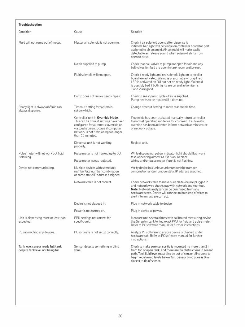
Troubleshooting
Condition Cause Solution
Fluid will not come out of meter Master air solenoid is not opening Check if air solenoid opens after dispense is initiated Red light will be visible on controller board for port assigned to air solenoid Air solenoid will make easily detectable air release sound when solenoid shifts from open to close
No air supplied to pump Check that ball valves to pump are open for air and any ball valves for fluid are open in tank room and by reel
Fluid solenoid will not open Check if ready light and red solenoid light on controller board are activated Wiring is presumably wrong if red LED is activated on DU but not on ready light Solenoid is possibly bad if both lights are on and action items 1 and 2 are good
Pump does not run or needs repair Check to see if pump cycles if air is supplied Pump needs to be repaired if it does not
Ready light is always on/fluid can always dispense
Timeout setting for system is set very high
Change timeout setting to more reasonable time
Controller unit in Override Mode This can be done if settings have been configured for automatic override or via touchscreen Occurs if computer network is not functioning for longer than 10 minutes
If override has been activated manually return controller to normal operating mode via touchscreen If automatic override has been activated inform network administrator of network outage
Dispense unit is not working properly
Replace unit
Pulse meter will not work but fluid is flowing
Pulse meter is not hooked up to DU While dispensing, yellow indicator light should flash very fast, appearing almost as if it is on Replace wiring and/or pulse meter if unit is not flashing Pulse meter needs replaced
Device not communicating Multiple devices with same unit number/site number combination or same static IP address assigned
Verify device has unique unit number/site number combination and/or unique static IP address assigned
Network cable is not correct Check network cable to make sure all device are plugged in and network wire checks out with network analyzer tool Note: Network analyzer can be purchased from any hardware store Device will connect to both end of wires to alert if terminals are correct
Device is not plugged in Plug in network cable to device
Power is not turned on Plug in device to power
Unit is dispensing more or less than expected
PPU settings not correct for specific unit
Measure unit several times with calibrated measuring device like Seraphin tank to find exact PPU for fluid and pulse meter Refer to PC software manual for further instructions
PC can not find any devices PC software is not setup correctly Analyze PC software to ensure device is checked under hardware tab Refer to PC software manual for further instructions
Tank level sensor reads full tank despite tank level not being full
Sensor detects something in blind zone
Check to make sure sensor tip is mounted no more than 2 in from top of open tank, and there are no obstructions in sensor path Tank fluid level must also be out of sensor blind zone to begin registering levels below full Sensor blind zone is 8 in closest to tip of sensor
20

This page intentionally left blank
21

This page intentionally left blank
22

This page intentionally left blank
23

alemite.com
® Alemite, LLC is a registered trademark
The contents of this publication are the copyright of the publisher and may not be reproduced (even extracts) unless prior written permission is granted Every care has been taken to ensure the accuracy of the information contained in this publication but no liability can be accepted for any loss or damage whether direct, indirect or consequential arising out of the use of the information contained herein
August 2021 · Form 671097 Version 3