aes ct1 notes
DESCRIPTION
SRM SOLAR NOTETRANSCRIPT

ME1148 – ALTERNATIVE SOURCES OF ENERGY
COURSE MATERIALS
UNIT I. BIOMASS
BIOMASS
The biomass is biological material derived from living or recently living organism. It’s an
organic matter derived from biological organism - plants, algae, animals etc. The biomass for
energy mean plant based material but biomass can equally apply to both animal and vegetable
derived material.
The sources of biomass are the forest and agricultural waste, animal waste, energy crops, co-
products in the crop field or industrial process wastes or by-products.
There are five basic categories of biomass source materials:
1. Wood: From forestry, agricultural activities or from wood processing.
2. Energy crops: High yield crops grown specifically for energy applications.
3. Agricultural residues: Residues from agriculture harvesting or processing.
4. Food waste: Waste from food manufacture, preparation and processing as well as post-
consumer wastes.
5. Industrial waste and co-products : From manufacturing and industrial processes
The energy conversion from biomass can be either bio-chemical (Fermentation or digestion)
or thermo-chemical methods to covert the biomass (solid fuel) into liquid or gaseous fuels. For
electricity generation, two most competitive technologies are direct combustion and gasification.
Typical plant sizes at present range from 0.1 to 50 MW. Co-generation applications are very
efficient and economical. Fluidized bed combustion (FBC) is efficient and flexible in accepting
varied types of fuels. Gasifiers first convert solid biomass into gaseous fuels which is then used
through a steam cycle or directly through gas turbine/I.C.engine. Biomass materials used for
power generation include bagasse, rice husk, straw, cotton stalk, coconut shells, soya husk, de-
oiled cakes, coffee waste, jute wastes, ground nut shells and saw dust etc.

Biomass is renewable, widely available, carbon-neutral and has the potential to provide
significant employment in the rural areas. Biomass is also capable of providing firm energy.
About 32% of the total primary energy use in the country is still derived from biomass and more
than 70% of the country’s population depends upon it for its energy needs.
Ministry of New and Renewable Energy has realised the potential and role of biomass
energy in the Indian context and hence has initiated a number of programmes for promotion of
efficient technologies for its use in various sectors of the economy to ensure derivation of
maximum benefits Biomass power generation in India is an industry that attracts investments of
over Rs.600 Crores every year, generating more than 5000 million units of electricity and yearly
employment of more than 10 million man-days in the rural areas. For efficient utilization of
biomass, bagasse based cogeneration in sugar mills and biomass power generation have been
taken up under biomass power and cogeneration programme. The following diagram indicates
various biomass energy sources.
Fig.1.1 Sources of Biomass

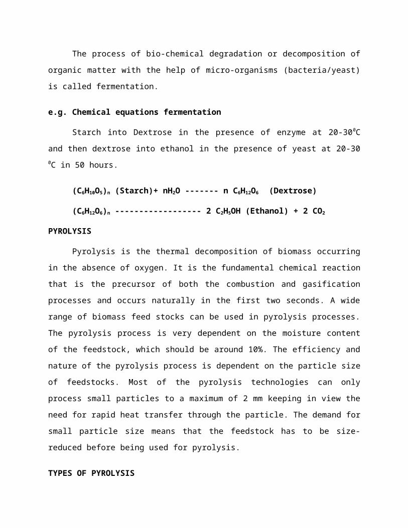
FERMENTATION
The process of bio-chemical degradation or decomposition of organic matter with the
help of micro-organisms (bacteria/yeast) is called fermentation.
e.g. Chemical equations fermentation
Starch into Dextrose in the presence of enzyme at 20-300C and then dextrose into ethanol
in the presence of yeast at 20-30 0C in 50 hours.
(C6H10O5)n (Starch)+ nH2O ------- n C6H12O6 (Dextrose)
(C6H12O6)n ------------------ 2 C2H5OH (Ethanol) + 2 CO2
PYROLYSIS
Pyrolysis is the thermal decomposition of biomass occurring in the absence of oxygen. It
is the fundamental chemical reaction that is the precursor of both the combustion and gasification
processes and occurs naturally in the first two seconds. A wide range of biomass feed stocks can
be used in pyrolysis processes. The pyrolysis process is very dependent on the moisture content
of the feedstock, which should be around 10%. The efficiency and nature of the pyrolysis
process is dependent on the particle size of feedstocks. Most of the pyrolysis technologies can
only process small particles to a maximum of 2 mm keeping in view the need for rapid heat
transfer through the particle. The demand for small particle size means that the feedstock has to
be size-reduced before being used for pyrolysis.
TYPES OF PYROLYSIS
Pyrolysis processes can be categorized as slow pyrolysis or fast pyrolysis. Fast pyrolysis is
currently the most widely used pyrolysis system. Slow pyrolysis takes several hours to complete
and results in biochar as the main product. On the other hand, fast pyrolysis yields 60% bio-oil
and takes seconds for complete pyrolysis. In addition, it gives 20% biochar and 20% syngas. Fast
pyrolysis processes include open-core fixed bed pyrolysis, ablative fast pyrolysis, cyclonic fast
pyrolysis, and rotating core fast pyrolysis systems.
The essential features of a fast pyrolysis process are given below:
1. Very high heating and heat transfer rates, which require a finely ground feed
2. Carefully controlled reaction temperature of around 500oC in the vapour phase
3. Residence time of pyrolysis vapours in the reactor less than 1 sec
4. Quenching (rapid cooling) of the pyrolysis vapours to give the bio-oil product.
Fig.1.2. Biomass Pyrolysis flow chart
Fig.1.3 Biomass pyrolysis plant cycle

The products of biomass pyrolysis include biochar, bio-oil and gases including methane,
hydrogen, carbon monoxide, and carbon dioxide. Depending on the thermal environment and the
final temperature, pyrolysis will yield mainly biochar at low temperatures, less than 4500C, when
the heating rate is quite slow, and mainly gases at high temperatures, greater than 8000C, with
rapid heating rates. The processes in the pyrolysis chamber are given below:
1. The dehydration or drying process occurs at around 100°C by the resulting steam mixed
into the gas flow and may be involved with subsequent chemical reactions, notably the
water-gas reaction if the temperature is sufficiently high enough.
2. The pyrolysis (or devolatilization) process occurs at around 200-300°C. Volatiles are
released and char is produced, resulting in up to 70% weight loss for coal.
3. The combustion process occurs as the volatile products and some of the char reacts with
oxygen to primarily form carbon dioxide and small amounts of carbon monoxide, which
provides heat for the subsequent gasification reactions. C + O2 ------------ CO2
4. The gasification process occurs as the char reacts with carbon and steam to produce
carbon monoxide and hydrogen, via the reaction, C + H2O ------------ CO + H2
5. In addition, the reversible gas phase water gas shift reaction reaches equilibrium very
fast at the temperatures in a gasifier. This balances the concentrations of carbon
monoxide, steam, carbon dioxide and hydrogen. CO + H2O ------------ CO2 + H2
Fig.1.4 Biomass Pyrolysis Products

Pyrolysis can be performed at relatively small scale and at remote locations which
enhance energy density of the biomass resource and reduce transport and handling costs. Heat
transfer is a critical area in pyrolysis as the pyrolysis process is endothermic and sufficient heat
transfer surface has to be provided to meet process heat needs.
Pyrolysis offers a flexible and attractive way of converting solid biomass into an easily
stored and transported liquid, which can be successfully used for the production of heat, power
and chemicals.
GASIFICATION
Gasification is thermo-chemical conversion process that converts organic or fossil based
carbonaceous material into carbon monoxide, hydrogen and carbon dioxide (gaseous fuels). This
is achieved by reacting the material at high temperatures (>700 °C), without combustion, with a
controlled amount of oxygen and/or steam. The resulting gas mixture is
called syngas (from synthesis gas or synthetic gas) or producer gas and is itself a fuel.
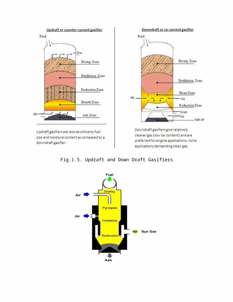
TYPES OF GASIFIERS
The gasifiers are classified based on the gas flow direction in the bed. The gas flow is
upward in the up-draft, downward in down-draft, perpendicular in the cross flow type. A fixed
bed of carbonaceous fuel (e.g. coal or biomass) through which the "gasification agent" (steam,
oxygen and/or air) flows in counter-current configuration. The ash is either removed in the dry
condition or as a slag.
The slagging gasifiers have a lower ratio of steam to carbon, achieving temperatures
higher than the ash fusion temperature. Thermal efficiency is high as the temperatures in the gas
exit are relatively low. In the gasification of fine, undensified biomass such as rice hulls, it is
necessary to blow air into the reactor by means of a fan. This creates very high gasification
temperature, as high as 1000 C.
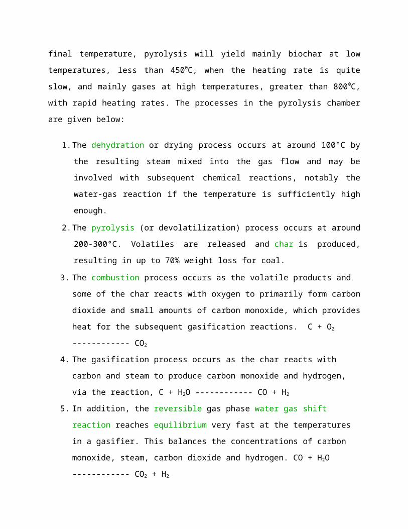
Fig.1.5. Updraft and Down Draft Gasifiers
Fig.1.6 Cross Flow Gasifier

Comparison of advantages/disadvantages of updraft, downdraft and crossdraft gasifiers
Table 1.1. Comparison of conventional gasifiers
Type of
Gasifiers
Advantages Disadvantages
Updraft Small pressure drop, good thermal
efficiency, small tendency to slag
Great sensitivity to tar/moisture ,
long time, poor reaction capability
Downdraft Flexible adaptation of gas production to
load, low sensitivity to charcoal dust
and tar content
Taller design, no feasibility for
small particle size of fuel
Crossdraft Shorter design height, quick response to
loads, flexible gas production
Very high sensitivity to slag
formation, high pressure drop
FLUIDIZED BED GASIFICATION/COMBUSTION
The fluidized bed can be classified as bubbling fluidized bed and circulation fluidized
bed. The unburnt fuel particles and bed particles are recovered in circulating bed and this gives
better conversion (gasification) efficiency than the bubbling bed gasifier. The prepared biomass
fuel has been sent to the gasifier and the fluidization velocity is given to the bed through fan. The
fluidized biomass particles are gasified through the partial combustion of biomass and the
producer gas in cleaned through cyclone separator and scrubber/filters before admitting the gas
to applications. In the fluidized bed concept, the biomass particles are gasified and burnt in the
floating condition by supplying air with the fluidization velocity. The fluidized bed can be
operated as atmospheric or pressurized bed conditions.

Fig.1.7. Bubbling and Circulating Fluidised Bed Gasification/Combustion
ADVANTAGES OF FLUIDIZED BED GASIFICATION/COMBUSTION
- Greater fuel flexibility and types of fuels of CV from 3,300 kJ/kg to 33,000 kJ/kg.
- Good heat storage capacity ensures complete combustion.
- Quick start up.
- Higher combustion efficiency (99%) and high output rate.
- Consistency in combustion rate and usage of high moisture fuels.
- Low temperature combustion leads to less corrosion due to alkali compounds.
- Less boiler floor area than other grate systems
- Uniform temperature throughout the furnace volume.
- Reduced emission due to NOx.
- Reduced SOx with less expense with limestone addition in bed.
- Operation is as simple as oil fired boiler.
CALORIFIC VALUE
The quantity of heat liberated during complete burning of 1 kg of fuel. The products of
combustion is cooled to the original room temperature (initial condition) and the total heat value
obtained is called as Gross calorific value (GCV) or Higher heating value whereas the products
of combustion is not cooled and the heat obtained in this combustion process is called as Net
calorific value (NCV) or lower heating value. The GCV is an indicative value and it can be
calculated using Dulong’s formula based on its components fraction. The NCV is useful while
designing the furnace or combustor.
GCV = 33800 C + 144000 (H – O/8) + 9270 S …………… kJ/kg
NCV = GCV – 2466 x (9 H + Moisture) ………………………………. kJ/kg
Where, C, H, O and S are in mass fraction.
NCV for wood having 25% Moisture = 14000 kJ/kg
NVC for charcoal having 8% moisture = 28000 kJ/kg
BIOMASS FUEL PROPERTIES FOR BIOMASS GASIFIER SELECTION
Need for selection of right gasifier for each fuel. Biomass fuels available for gasification
include charcoal, wood and wood waste (branches, twigs, roots, bark, wood shavings and
sawdust) as well as a multitude of agricultural residues (maize cobs, coconut shells, coconut
husks, cereal straws, rice husks, etc.) and peat. The following are the data required while
choosing a fuel and gasifier and the producer gas produced is dependent on these:
1. Energy Content ( Higher and lower heating values)
2. Moisture content
3. Volatile matter

4. Ash content and ash chemical composition
5. Reactivity
6. Particle size and distribution
7. Bulk density (e.g for Wood = 400 kg/m3)
TYPES OF BIOGAS DIGESTER PLANTS
1. Fixed Dome Digester plant
2. Floating Dome Digester plant
Floating gas-holder type of plant
A well is made out of concrete called the digester tank T, which is divided into two parts.
One part is an inlet, from where the slurry is fed to the tank. The cylindrical dome H of the tank
is made out of stainless steel that floats on the slurry and collects the gas generated. Hence it is
called floating gas-holder type of bio gas plant. The slurry is fermented for about 50 days. As
more gas is made by the bacterial fermentation, the pressure inside H increases. The gas can be
taken out from outlet pipe V. The decomposed matter expands and overflows into the next
chamber in tank T, which is removed by the outlet pipe to the overflow tank and used as manure
for cultivation purposes.

Fig.1.8 Floating drum type of plant
A well and a dome are made out of concrete called the digester tank T. This dome is
fixed and thus it is called fixed dome type of bio gas plant. The function of the plant is similar to
the floating holder type bio gas plant. The used slurry expands and overflows into the overflow
tank. The cobar gas is cleaned by supplying through water and then used in cooking or heating
applications.
In the floating gas-holder type of plant, the floating chamber is made of stainless steel.
This is expensive and needs continuous maintenance and supervision for non-rust. This does not
arise in the fixed dome type of bio gas plant as everything is made of concrete. The volume of
fixed dome type of biogas is fixed. So if the gas pressure increases inside, it may cause damage
to the concrete dome. This does not happen in the floating holder type of bio gas plant.

Fig.1.9. Fixed Digester biogas plant
BIOGAS
The biogas power plant works on fermentation concept. The feed is mixed with water and
supplied to the digester and allowed there several days. The combustible gas contains methane
comes out of it.
The typical composition of biogas is given below:
CH4 = 60 %, CO2 =35%, H2 = 3.5%, N2= 1%, H2S = 0.3 %, CO = 0.2%.
The percent of methane gas plays major role in combustion and the quality of gas depends on the
methane only.
Gross Calorific value: 23 MJ/m3.

Ignition temperature: 650 C.
Comparision of fixed dome and floating drum biogas plant
Table.1.2 Comparison of biogas plants
FIXED DOME BIOGAS PLANT FLOATING DOME BIOGAS PLANTCompletely masonry concrete structure Masonry digester with steel or composite or
plastic gas holderLower cost Higher cost 20-30% more than fixed domeLow maintenance High maintenanceLow reliability Highly reliableHigh masonry skill is required Low masonry skill is requiredHigh supervision is required Less fabrication skill is requiredGas pressure is variable so complicated appliance design
Gas pressure is constant so simple appliance design
BIOGAS POWER PLANT
The biogas power plant consists of more number of biogas plants are connected to
produce large quantity of biogas to produce electricity using IC engines and the effluent is de-
watered and converted as compost and manure. The major parts of the plants are fuel preparation
systems, anaerobic digester, anaerobic digestrate storage, power generation unit and effluent
treatment systems.
Digester design
Energy available from a biogas plant, E = Hb Vb
- Combustion efficiency of burner (around 60%)
Hb – Heat of combustion per unit volume in kJ/m3 = CV of methane x Fraction of methane
Vb - Volume of the biogas, m3 = C md
Where C – Volume of biogas per unit dry mass (0.2-0.4 m3 per kg)
md – Mass of dry input (kg)
Volume of fluid in the digester, Vf = md /
Where - density of dry material in the fluid (around 50 kg/m3)

Volume of the digester, Vd = Volume flow rate of digester fluid x retention time
Retention time is usually 8 – 20 days.
Problem.1.1
The following data are given for a family biogas digester suitable for the output of five cows: 20
days retention time, 30 C temperatures, 2 kg dry matter consumed per day, biogas yield 0.24 m3
per kg. The efficiency of burner is 60%, methane proportion is 0.8. Heat of combustion of
methane is 28 MJ/m3. Find the volume of biogas plant digester and power available from the
digester. Assume density of dry matter = 50 kg/m3.
Solution:
Mass of dry input per day, md = 2 x 5 = 10 kg
Fluid volume, Vf = md / = 10/50 = 0.2 m3.
Digester volume, Vd = 0.2 x 20 days = 4 m3.
Volume of biogas, Vb = C md = 0.24 x 10 = 2.4 m3 per day.
Power available from the digester, E = Hb Vb = 0.6 x (28x0.8)x 2.4 = 32.25 MJ/day
E = 32.25/3.6 = 8.8 kWh per day
E = 32.25 x 10⁶ / (24 x 3600) = 373 W. (Continuous thermal output)
Problem 1.2
The following data are given for a community biogas digester suitable for the output of 125
cows: 20 days retention time, 30 C temperatures, 2 kg dry matter consumed per day, biogas
yield 0.25 m3 per kg. The efficiency of burner is 60%, methane proportion is 0.7. Heat of
combustion of methane is 30 MJ/m3. Find the size of biogas plant digester and power available
from the digester. Assume density of dry matter = 50 kg/m3.
Solution:
Mass of dry input per day, md = 2 x 125 = 250 kg

Fluid volume, Vf = md / = 250/50 = 5 m3.
Digester volume, Vd = 5 x 20 days = 100 m3.
Volume of biogas, Vb = C md = 0.25 x 250 = 62.5 m3 per day.
Power available from the digester, E = Hb Vb = 0.6 x (30x0.7)x 62.5 = 787.5 MJ/day
E = 787.5 x 10⁶ / (24 x 3600) = 9115 W. (Continuous thermal output)
Digester volume, Vd = D2 x H / 4 ….. (Cylindrical volume, D-Diameter, H-Height)
Preferred size is D = H, 100 = D3 / 4. D = (4 x 100 / )1/3 = 5 m.
Size of digester: Diameter = 5m, Height = 5m.
Advantages of biomass energy
1. Versatile and renewable
2. No net CO2 emissions (ideally) and emits less SO2 and NOx than fossil fuels
3. Production of alternate fuels like alcohol fuels.
4. Methanol and ethanol can be blended with diesel fuels for IC engine applications.
Disadvantages of biomass energy
1. Low energy density/yield
2. Land conversion (Biodiversity loss, possible decrease in agricultural food productivity)
3. Usual problems associated with intensive agriculture
- Nutrient pollution, - Soil depletion, - Soil erosion, - Other water pollution problems etc.

UNIT II.SOLAR ENERGY
SOLAR RADIATION
The sun’s surface temperature is around 5300 C. The solar radiation from the sun is
around 178 TW. The solar rays reach the earth surface through the atmosphere. The radiation
above the atmosphere is called as extra terrestrial radiation and the radiation below the
atmosphere is called as terrestrial radiation or global radiation.
Global radiation = Beam or direct radiation + Diffuse or scattered radiation.
The direct radiation reaches the earth from sun directly but diffuse radiation is due to
scattered effect of atmosphere and the particles in the air. The reflected rays by the earth surface
is called albedo. The solar energy potential or intensity on earth surface is around 0-1 kW/m2
( night to noon). The solar constant is defined as the solar radiation incidence per m 2 of
atmosphere . Its value is 1367 W /m2.
Fig.2.1. Solar radiation components
The angles in solar geometry:
Altitude angle (): The angle between beam radiation and the ground.
Incidence angle: The angle of incidence of beam radiation from the zenith. In case of Horizontal surface collectors the incidence angle is equal to zenith angle.
Zenith angle: The angle between the beam radiation and Vertical plane.

Fig.2.2. Solar Geometry
The solar azimuth angle is the azimuth angle of the sun. It defines in
which direction the sun is, whereas the solar zenith angle or solar elevation defines how high the
sun is. (The elevation is the complement of the zenith.) There are several conventions for the solar azimuth; however it is traditionally defined as the angle between a line due south and the shadow cast by a vertical rod on Earth.
SOLAR RADIATION MEASUREMENTS
1. Pyranometer : To measure global radiation (both beam and diffuse radiation)

Fig.2.3. Pyranometer
The quartz domes collects the beam and diffuse incident solar radiations. The sensing
element is subjected to heating by solar radiation and its thermal resistance is used to measure
the global radiation by using the emf generated.
2. Pyrheliometer : To measure beam radiation.
Pyrheliometer has a collimator tube to collect the beam radiation component and the thermal
resistance of black absorber plate is used to determine the intensity of the beam radiation. This
narrow tube allows only beam radiation to reach the sensing element.
Fig.2.4. Pyrheliometer
3. Pyrgeometer: To measure IR and long wave radiation.

Fig.2.5. Pyrgeometer
4. Sunshine recorder: To measure the actual
sunshine daily hours. The working
principle is the based on the length of
card board paper burnt in the spherical
glass. The spherical bowl is calibrated in
such a way that the length of paper burnt
is directly proportional to the active solar
hours.
Fig.2.6. Sunshine recorder
SOLAR THERMAL ENERGY TECHNOLOGIES
The solar collectors are broadly classified as solar thermal collectors and photovoltaic cells. Then the thermal collectors are classified as follows:
I. Based on Concentration
- Non-concentrated .. Flat plate collectors
- Concentrated collectors … Parabolic collectors
II. Based on sun-tracking
- Single axis tracking . ….. Parabolic and cylindrical trough collectors
- Two-axis tracking …… Parabolic dish collectors, Heliostat Mirror field

SOLAR FLAT PLATE COLLECTORS
The flat plate collectors contains absorber plate (to increase the heat absorption rate) ,
absorber tube ( to carry the heat transfer fluids), insulation on all sides except aperture area, glass
cover (to transmit the incident rays and retain rays inside the collector) etc. The working
temperature range of this collector is around 60-120 C. The major classification is Flat plate
collector, Evacuated tube collector, compound parabolic collectors. It’s suitable for mainly
domestic thermal applications. The flat plate collectors can be classified further as liquid heaters
and air heaters.
Fig.2.7.Solar flat plate collector
Problem. 2.1
In a solar water heater, the collector plate is at 87 C and glass cover is at 67 C. Heat from
collector plate is lost to the air by convection and to the glass cover by radiation. If the heat
transfer co-efficient by convection is 4.6 W/m2 K, find the heat loss from the collector plate per
hour per m2 surface area. Also find the equivalent radiation heat transfer co-efficient. Assume
emissivity of plate is 0.2 and emissivity of glass is 0.3 and radiation shape factor is 1.

Solution :
Suffix-p for Plate and g for Glass.
Equivalent emissivity, equi = 1/ { [ 1/p + 1/ g] -1 } = 0.136
The radiation heat transfer coefficient
hr = equi ( Tp4 – Tg4 ) / ( Tp – Tg) = 1.32 W /m2 –K
Total heat loss by collector plate, Qt = (hc+hr) As ( Tp – Tg) = 118.4 W/m2.
Problem 2.2
A solar water heating plant with a FPC has to be designed based on the following data: Daily solar radiation = 5 kWh/m2 per dayHot water consumption = 1000 kg per dayHot water temperature = 45 CCold water temperature = 14 CPlant mean efficiency = 48 %.Isobaric specific heat of water = 1.163 W h/kg-KDetermine total collector surface area and the number of solar collector modules required if a single module has an area of 2.2 m2.
Solution:
Daily heat requirement,
Qhw = m Cp (Th – Tc)
= 1000 x 1.163 x (45-14) = 36053 W h /day
Daily useful heat output by ignoring heat losses,
Q = Incident radiation x Efficiency = 5 x 0.48 = 2.4 kWh/day
Required collector surface area, A = Qhw / Q = 15.02 m2
No. of collector panels required, N = 15.02 / 2.2 = 7 collectors