advanced virgo: a second-generation interferometric ... virgo.pdf · advanced virgo: a...
TRANSCRIPT

This content has been downloaded from IOPscience. Please scroll down to see the full text.
Download details:
IP Address: 134.214.188.172
This content was downloaded on 28/12/2014 at 15:50
Please note that terms and conditions apply.
Advanced Virgo: a second-generation interferometric gravitational wave detector
View the table of contents for this issue, or go to the journal homepage for more
2015 Class. Quantum Grav. 32 024001
(http://iopscience.iop.org/0264-9381/32/2/024001)
Home Search Collections Journals About Contact us My IOPscience

Advanced Virgo: a second-generationinterferometric gravitational wave detector
F Acernese1,2, M Agathos3, K Agatsuma3, D Aisa4,5,N Allemandou6, A Allocca7,8, J Amarni9, P Astone10,G Balestri8, G Ballardin11, F Barone1,2, J-P Baronick9,M Barsuglia9, A Basti12,8, F Basti10, Th S Bauer3,V Bavigadda11, M Bejger13, M G Beker3, C Belczynski14,D Bersanetti15,16, A Bertolini3, M Bitossi11,8, M A Bizouard17,S Bloemen3,18, M Blom3, M Boer19, G Bogaert19, D Bondi16,F Bondu20, L Bonelli12,8, R Bonnand6, V Boschi8, L Bosi5,T Bouedo6, C Bradaschia8, M Branchesi21,22, T Briant23,A Brillet19, V Brisson17, T Bulik14, H J Bulten24,3, D Buskulic6,C Buy9, G Cagnoli25, E Calloni26,2, C Campeggi4,5,B Canuel11,41, F Carbognani11, F Cavalier17, R Cavalieri11,G Cella8, E Cesarini27, E Chassande- Mottin9, A Chincarini16,A Chiummo11, S Chua23, F Cleva19, E Coccia28,29,P-F Cohadon23, A Colla30,10, M Colombini5, A Conte30,10,J-P Coulon19, E Cuoco11, A Dalmaz6, S D’Antonio27,V Dattilo11, M Davier17, R Day11, G Debreczeni31,J Degallaix25, S Deléglise23, W Del Pozzo3, H Dereli19,R De Rosa26,2, L Di Fiore2, A Di Lieto12,8, A Di Virgilio8,M Doets3, V Dolique25, M Drago32,33, M Ducrot6, G Endrőczi31,V Fafone28,27, S Farinon16, I Ferrante12,8, F Ferrini11,F Fidecaro12,8, I Fiori11, R Flaminio25, J-D Fournier19,S Franco17, S Frasca30,10, F Frasconi8, L Gammaitoni4,5,F Garufi26,2, M Gaspard17, A Gatto9, G Gemme16, B Gendre19,E Genin11, A Gennai8, S Ghosh3,18, L Giacobone6,A Giazotto8, R Gouaty6, M Granata25, G Greco22,21, P Groot18,G M Guidi21,22, J Harms22, A Heidmann23, H Heitmann19,P Hello17, G Hemming11, E Hennes3, D Hofman25,P Jaranowski34, R J G Jonker3, M Kasprzack17,11,F Kéfélian19, I Kowalska14, M Kraan3, A Królak35,36,A Kutynia35, C Lazzaro37, M Leonardi32,33, N Leroy17,N Letendre6, T G F Li3, B Lieunard6, M Lorenzini28,27,V Loriette38, G Losurdo22, C Magazzù8, E Majorana10,I Maksimovic38, V Malvezzi28,27, N Man19, V Mangano30,10,M Mantovani11,8, F Marchesoni39,5, F Marion6, J Marque11,42,F Martelli21,22, L Martellini19, A Masserot6, D Meacher19,
Classical and Quantum Gravity
Class. Quantum Grav. 32 (2015) 024001 (52pp) doi:10.1088/0264-9381/32/2/024001
0264-9381/15/024001+52$33.00 © 2015 IOP Publishing Ltd Printed in the UK 1

J Meidam3, F Mezzani10,30, C Michel25, L Milano26,2,Y Minenkov27, A Moggi8, M Mohan11, M Montani21,22,N Morgado25, B Mours6, F Mul3, M F Nagy31, I Nardecchia28,27,L Naticchioni30,10, G Nelemans3,18, I Neri4,5, M Neri15,16,F Nocera11, E Pacaud6, C Palomba10, F Paoletti11,8, A Paoli11,A Pasqualetti11, R Passaquieti12,8, D Passuello8,M Perciballi10, S Petit6, M Pichot19, F Piergiovanni21,22,G Pillant11, A Piluso4,5, L Pinard25, R Poggiani12,8,M Prijatelj11, G A Prodi32,33, M Punturo5, P Puppo10,D S Rabeling24,3, I Rácz31, P Rapagnani30,10, M Razzano12,8,V Re28,27, T Regimbau19, F Ricci30,10, F Robinet17, A Rocchi27,L Rolland6, R Romano1,2, D Rosińska40,13, P Ruggi11,E Saracco25, B Sassolas25, F Schimmel3, D Sentenac11,V Sequino28,27, S Shah3,18, K Siellez19, N Straniero25,B Swinkels11, M Tacca9, M Tonelli12,8, F Travasso4,5,M Turconi19, G Vajente12,8,43, N van Bakel3,M van Beuzekom3, J F J van den Brand24,3,C Van Den Broeck3, M V van der Sluys3,18, J van Heijningen3,M Vasúth31, G Vedovato37, J Veitch3, D Verkindt6,F Vetrano21,22, A Viceré21,22, J-Y Vinet19, G Visser3,H Vocca4,5, R Ward9,44, M Was6, L-W Wei19, M Yvert6,A Zadro żny35 and J-P Zendri37
1Università di Salerno, Fisciano, I-84084 Salerno, Italy2 INFN, Sezione di Napoli, Complesso Universitario di Monte S.Angelo, I-80126Napoli, Italy3 Nikhef, Science Park, 1098 XG Amsterdam, The Netherlands4 Università di Perugia, I-06123 Perugia, Italy5 INFN, Sezione di Perugia, I-06123 Perugia, Italy6 Laboratoire d’Annecy-le-Vieux de Physique des Particules (LAPP), Université deSavoie, CNRS/IN2P3, F-74941 Annecy-le-Vieux, France7Università di Siena, I-53100 Siena, Italy8 INFN, Sezione di Pisa, I-56127 Pisa, Italy9 APC, AstroParticule et Cosmologie, Université Paris Diderot, CNRS/IN2P3, CEA/Irfu, Observatoire de Paris, Sorbonne Paris Cité, 10, rue Alice Domon et LéonieDuquet, F-75205 Paris Cedex 13, France10 INFN, Sezione di Roma, I-00185 Roma, Italy11 European Gravitational Observatory (EGO), I-56021 Cascina, Pisa, Italy12 Università di Pisa, I-56127 Pisa, Italy13 CAMK-PAN, 00-716 Warsaw, Poland14Astronomical Observatory Warsaw University, 00-478 Warsaw, Poland15Università degli Studi di Genova, I-16146 Genova, Italy16 INFN, Sezione di Genova, I-16146 Genova, Italy17 LAL, Université Paris-Sud, IN2P3/CNRS, F-91898 Orsay, France18 Department of Astrophysics/IMAPP, Radboud University Nijmegen, PO Box 9010,6500 GL Nijmegen, The Netherlands19 ARTEMIS, Université Nice-Sophia-Antipolis, CNRS and Observatoire de la Côted’Azur, F-06304 Nice, France20 Institut de Physique de Rennes, CNRS, Université de Rennes 1, F-35042 Rennes, France
Class. Quantum Grav. 32 (2015) 024001 F Acernese et al
2
21 Università degli Studi di Urbino ‘Carlo Bo’, I-61029 Urbino, Italy22 INFN, Sezione di Firenze, I-50019 Sesto Fiorentino, Firenze, Italy23 Laboratoire Kastler Brossel, ENS, CNRS, UPMC, Université Pierre et Marie Curie,F-75005 Paris, France24 VU University Amsterdam, 1081 HV Amsterdam, The Netherlands25 Laboratoire des Matériaux Avancés (LMA), IN2P3/CNRS, Université de Lyon, F-69622 Villeurbanne, Lyon, France26 Università di Napoli ‘Federico II’, Complesso Universitario di Monte S.Angelo, I-80126 Napoli, Italy27 INFN, Sezione di Roma Tor Vergata, I-00133 Roma, Italy28 Università di Roma Tor Vergata, I-00133 Roma, Italy29 INFN, Gran Sasso Science Institute, I-67100 L’Aquila, Italy30 Università di Roma ‘La Sapienza’, I-00185 Roma, Italy31Wigner RCP, RMKI, H-1121 Budapest, Konkoly Thege Miklós út 29-33, Hungary32 Università di Trento, I-38123 Povo, Trento, Italy33 INFN, Trento Institute for Fundamental Physics and Applications, I-38123 Povo,Trento, Italy34 University of Białystok, 15-424 Białystok, Poland35NCBJ, 05-400 Świerk-Otwock, Poland36 IM-PAN, 00-956 Warsaw, Poland37 INFN, Sezione di Padova, I-35131 Padova, Italy38 ESPCI, CNRS, F-75005 Paris, France39 Università di Camerino, Dipartimento di Fisica, I-62032 Camerino, Italy40 Institute of Astronomy, 65-265 Zielona Góra, Poland
E-mail: [email protected]
Received 18 August 2014, revised 16 October 2014Accepted for publication 20 October 2014Published 18 December 2014
AbstractAdvanced Virgo is the project to upgrade the Virgo interferometric detector ofgravitational waves, with the aim of increasing the number of observablegalaxies (and thus the detection rate) by three orders of magnitude. The projectis now in an advanced construction phase and the assembly and integrationwill be completed by the end of 2015. Advanced Virgo will be part of anetwork, alongside the two Advanced LIGO detectors in the US and GEO HFin Germany, with the goal of contributing to the early detection of gravita-tional waves and to opening a new window of observation on the universe. Inthis paper we describe the main features of the Advanced Virgo detector andoutline the status of the construction.
Keywords: gravitational wave detectors, laser interferometry, gravitational wavesPACS numbers: 04.80.Nn, 95.55.Ym
(Some figures may appear in colour only in the online journal)
41 Present address: LP2N, Institut d’Optique d’Aquitaine, F-33400 Talence, France42 Present address: Bertin Technologies, F-13290 Aix-en-Provence, France43 Present address: California Institute of Technology, Pasadena, CA 91125, USA44 Present address: Centre for Gravitational Physics, The Australian National University, Canberra, ACT 0200, Australia
Class. Quantum Grav. 32 (2015) 024001 F Acernese et al
3
1. Introduction: the scope of the Advanced Virgo upgrade
Advanced Virgo (AdV) is the project to upgrade the Virgo detector [1] to a second generationinstrument. It is designed to achieve a sensitivity of about one order of magnitude better thanthat of Virgo, which corresponds to an increase in the detection rate by about three orders ofmagnitude. AdV will be part of the international network of detectors aiming to open the wayto gravitational wave (GW) astronomy [2–4]. With respect to Virgo, most of the detectorsubsystems have to deliver a significantly improved performance to be compatible with thedesign sensitivity. The AdV design choices were made on the basis of the outcome of thedifferent R&D investigations carried out within the GW community and the experiencegained with Virgo, while also taking into account budget and schedule constraints. The AdVupgrade was funded in December 2009 and is currently in an advanced phase of installation.In March 2014 a Memorandum of Understanding for full data exchange, joint data analysisand publication policy with the LIGO Scientific Collaboration was renewed, thus strength-ening the world-wide network of second generation detectors (including AdV, the twoAdvanced LIGO [5] and GEO HF[6]).
In this introduction we briefly describe the main upgrades foreseen in the AdV design.Comprehensive and more detailed descriptions can be found in the following sections and inthe technical design report (TDR) [7].
Interferometer (ITF) optical configuration. AdV will be a dual-recycled ITF. In additionto the standard power recycling (PR), a signal-recycling (SR) cavity will also be present. Thetuning of the SR parameter allows changing the shape of the sensitivity curve and optimizingthe detector for different astrophysical sources. To reduce the impact of the thermal noise ofthe mirror coatings in the mid-frequency range, the beam spot size on the test masses has beenenlarged. Therefore, unlike Virgo, the beam waist will be placed close to the center of the3 km Fabry–Perot (FP) cavities. The cavity finesse will be higher than that of Virgo: areference value of 443 has been chosen. Having a larger beam requires the installation oflarger vacuum links in the central area and new mode matching telescopes (MMT) at the ITFinput/output. Locking all of the cavities at the same time might be difficult. To ease the lockof the full ITF, a system of auxiliary green lasers is being developed.
Increased laser power. Improving the sensitivity at high frequency requires high laserpower45. The AdV reference sensitivity is computed assuming 125W entering the ITF, afterthe input mode cleaner (IMC). Therefore, considering the losses of the injection system, thelaser must provide a power of at least 175 W. A 200W laser, based on fiber amplifiers, will beinstalled after 2018, while during the first years of operation (at a lower power) AdV will usethe Virgo laser, capable of providing up to 60 W. The input optics for AdV must be compliantwith the ten-fold increase in optical power. Specifically designed electro-optic modulators andFaraday isolators (FI) able to withstand high power have been developed and a DC readoutscheme will be used, requiring a new design of the output mode cleaner (OMC). A sophis-ticated thermal compensation system (TCS) has been designed to cope with thermallyinduced aberrations (but also with losses induced by intrinsic defects of the optics). Thesensing is based on Hartmann sensors and phase cameras, while ring heaters (RH) aroundseveral suspended optics will be used as actuators to change the radius of curvature (RoC).CO2 laser projectors, which shine on dedicated compensation plates (CP), allow the com-pensation of thermal lensing and optical defects.
45 Though squeezing is not part of the AdV baseline, the infrastructure has been prepared to host a squeezer insubsequent years.
Class. Quantum Grav. 32 (2015) 024001 F Acernese et al
4

Mirrors. To cope with the increased impact of radiation pressure fluctuations the AdVtest masses will be twice as heavy (42 kg) as those of Virgo. Fused silica grades withultra-low absorption and high homogeneity have been chosen for the most critical optics.State of the art polishing technology is used to reach a flatness better than 0.5 nm rms in thecentral area of the test masses. Low-loss and low-absorption coatings are used to limit as faras possible the level of thermal noise and the optical losses in the cavities, which eventuallydetermine the sensitivity in the high frequency range.
Stray light control. Scattered light could be a significant limitation on detector sensitivity.In order to limit phase noise caused by part of the light being back-scattered into the ITF, newdiaphragm baffles will be installed. These will be either suspended around the mirrors, orground-connected inside the vacuum links. All photodiodes to be used in science mode willbe seismically isolated and in vacuum. To this end, a compact vibration isolation system,accommodated inside a vacuum chamber, has been built. Five of these minitowers will beinstalled.
Payloads and vibration isolation. A new design of the payloads has been developed.This was triggered mainly by the need to suspend heavier mirrors, baffles and CP, whilecontrollability and mechanical losses have also been improved. The Virgo super attenuators(SA) already provide a seismic isolation compliant with AdV requirements. However, someupgrades are planned to take the new payload design into account and to further improverobustness in high seismicity conditions: the possibility to actively control the ground tilt willbe implemented.
General detector infrastructure. Important modifications have been undertaken in themain experimental hall, in order to be able to host the minitowers and upgrade the laboratorieswhere the laser, the input optics and the detection system are located, turning them intoacoustically isolated clean rooms. The vacuum has been upgraded by installing large cryo-traps at the ends of the 3 km pipes, in order to lower the residual pressure by a factor of about100. Several upgrades of the data acquisition and general-purpose electronics are foreseen forAdV, in order to keep up with the increasing number of channels and the more demandingcontrol system for the SR configuration, and to cope with the obsolescence of several boards.
2. Sensitivity goals
2.1. Target sensitivity for AdV
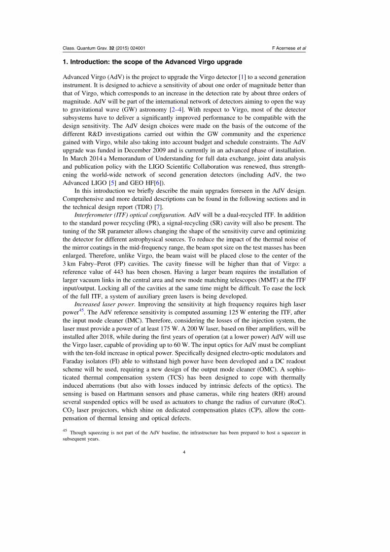
A target sensitivity curve for the new ITF was defined, based on the detector design and noisemodeling at that time (solid black line in figure 1) in the AdV TDR [7], which was approvedby the funding agencies in 2012. The curve corresponds to a detector configuration with125W at the ITF input and SR parameters chosen in order to maximize the sight distance forcoalescing binary neutron stars (BNS). The corresponding inspiral ranges46 are ∼140 Mpc forBNS (1.4 M⊙ each) and ∼1 Gpc for 30 ⊙M coalescing binary black holes (BBH).
Some basic assumptions are made in the sensitivity computation, which are to be con-sidered as system requirements. Some subsystem design choices were made to comply withthese requirements:
• input power: it is assumed that a laser power of 125W will be available in the TEM00
mode after the IMC;
46 The inspiral range is defined as the volume- and orientation-averaged distance at which a compact binarycoalescence gives a matched filter signal-to-noise ratio of 8 in a single detector [8].
Class. Quantum Grav. 32 (2015) 024001 F Acernese et al
5
• round trip losses: the power lost in a round trip inside an FP cavity must not exceed75 ppm;
• technical noises: all technical noises47 must be reduced to a level such that thecorresponding strain noise in amplitude is <0.1 of the design sensitivity in the 10 Hz-10 kHz frequency range.
However, the AdV detector is tunable in three ways: by changing the laser power, bychanging the transmissivity of the SR mirror (SRM) and by tuning the position of the SRM.The SRM transmittance influences the detector bandwidth, while the position of the SRM at amicroscopic scale changes the frequency of the maximal sensitivity. Thus, the presence of theSR cavity allows AdV to be thought of as a tunable detector (see section 3): the sensitivitycurve can be shaped in order to perform data-taking periods optimized to target differentastrophysical sources. For the sake of simplicity, we refer to three different operation modes:
• power recycled, 25 W;• dual recycled, 125 W, tuned signal recycling;• dual recycled, 125 W, detuned signal recycling (SR tuning chosen to optimize BNSinspiral range).
AdV will not initially be operated in the final configuration. The new features will createnew problems, which must be faced with a step-by-step approach. The above-mentioned
Figure 1. AdV sensitivity for the three benchmark configurations as defined in theTDR: early operation (dash-dotted line), 25 W input power, no SR; mid-term operation,wideband tuning (dashed line), 125 W input power, tuned SR; late operation, optimizedfor BNS (black solid line), 125 W input power, detuned SR (0.35 rad). In the legend,the inspiral ranges for BNS and BBH (each BH of 30 ⊙M ) in Mpc are reported. Thebest sensitivity obtained with Virgo+ is shown for comparison.
47 The distinction between fundamental and technical noise is common in the GW community, but not always clear.We define fundamental noises as those that require a large investment in infrastructure, a deep redesign of thedetector, or new technological developments in order to be suppressed (e.g. thermal noise, shot noise, seismic noise).We define technical noises as those that require a relatively limited investment in commissioning or upgrade to besuppressed (e.g. the noise generated by scattered light or electronics).
Class. Quantum Grav. 32 (2015) 024001 F Acernese et al
6
modes of operation correspond to commissioning steps of increasing complexity. Theyshould be considered as benchmark configurations, while the commissioning will progressthrough many intermediate steps. Periods of commissioning will be alternated with periods ofdata-taking and such plans will need to be coordinated with Advanced LIGO in order tomaximize the capabilities of the network.
Figure 1 compares the target sensitivity curves for the reference scenarios described, asdefined in the TDR48.
2.2. Further progress
Since the release of the TDR some progress has been made both in the design of the detectorand the modeling of the noise:
• The design of the payload has been finalized and the recoil mass, present in the Virgopayload, has been removed. Furthermore, experimental tests have shown that mechanicaldissipation at the level of the marionette is lower than previously assumed. This has led toa new modeling of the suspension thermal noise, which no longer limits the sensitivity atlow frequency (see section 6).
• The gravity gradient noise model has also evolved. It now uses the typical seismic noisespectrum measured on the Virgo site as input.
• We have started to add some of the technical noises that we know how to model to thenoise budget.
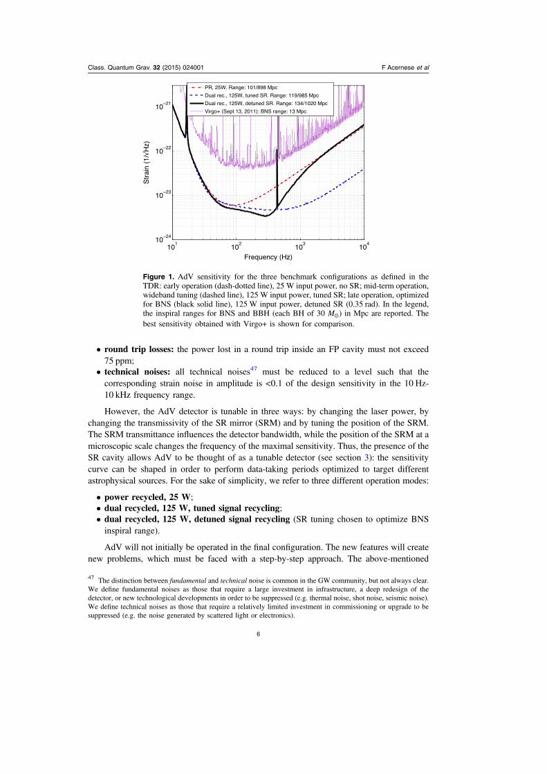
In figure 2 we show the result of this work (which must be considered as work inprogress).
Figure 2. The AdV reference sensitivity (solid black) compared to an AdV noise budget(dashed black) using the new models for suspension thermal noise, gravity gradientnoise and some modeled technical noises, computed in the configuration optimized forBNS detection with 125 W of input laser power. See section 2.1 for further details.
48 The sensitivity curves shown in this section have been plotted using GWINC, a MATLAB code developed withinthe LIGO Scientific Collaboration (LSC) [9] and adapted to AdV.
Class. Quantum Grav. 32 (2015) 024001 F Acernese et al
7
2.3. Timeline
One of the main goals of the AdV project is to start taking data in 2016. AdV will be operatedin two main phases.
• Early operation: the ITF configuration will be a power-recycled FP Michelson and thepower injected will not exceed 40 W. This configuration is, for many reasons, similar tothat of Virgo+. Thus, we expect a shorter commissioning period and faster progress in thesensitivity improvement. The achievable BNS inspiral range is larger than 100 Mpc.
• Late operation: the ITF will subsequently be upgraded by installing the SRM and thehigh-power (HP) laser, fulfilling the full specifications. The tentative date for thisupgrade is 2018, though this will depend on the joint plans for science runs agreed withthe partners in the network.
The installation and integration of the upgrades needed for the first phase and theiracceptance are scheduled to be completed by fall 2015. The commissioning of parts of thedetector will start prior to then:
• the commissioning of the IMC cavity started in June 2014, following its first lock;• in spring 2015, the beam will be available at the dark port, making it possible tocommission the detection system;
• a single 3 km arm will be available shortly after.
3. Optical design
The optical configuration of AdV was designed to maximize improvements in thedetector sensitivity, while inducing only minor changes to the infrastructure. Thevacuum enclosure, which housed the Virgo ITF, continues to constrain the cavity lengths for,AdV. As a consequence, the arm cavity length is 3 km, while the recycling cavities are∼12 m long.
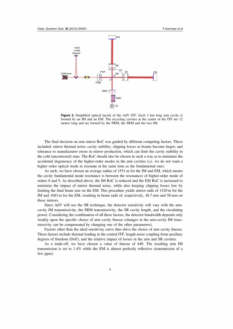
A sketch of the optical configuration is presented in figure 3. The core of AdV iscomposed of a dual recycled Michelson ITF with FP arm cavities.
3.1. Design of the arm cavities
The arm cavities have a bi-concave geometry, with each mirror, also known as test mass,having a concave RoC slightly larger than half the arm-cavity length to ensure the stability ofthe cavity. This near-concentric resonator configuration has been chosen for two main rea-sons: (1) to increase the beam size at the mirrors, thus averaging over a larger area of themirror surface and reducing the relative contribution of mirror-coating thermal noise andthermal gradient in the substrate; and (2) to limit the effect of radiation-pressure-inducedalignment instabilities.
With this type of topology the cavity waist is near the middle of the arm. In addition,having mirrors in the cavity with two different RoC displaces the cavity waist towards themirror with the smaller RoC, so that the beam size on that mirror is also reduced. We decidedto have a smaller beam on the input mirror (IM) to reduce the clipping loss in the recyclingcavities. This did not cause problems in terms of coating thermal noise since the IM havefewer coating layers compared to the end mirror (EM), meaning less thermal noise if the beamsizes are identical on both mirrors. We have thus chosen to have the EM with a larger radius,and therefore larger beam size, than the IM.
Class. Quantum Grav. 32 (2015) 024001 F Acernese et al
8
The final decision on arm mirror RoC was guided by different competing factors. Theseincluded: mirror thermal noise; cavity stability; clipping losses as beams become larger; andtolerance to manufacturer errors in mirror production, which can limit the cavity stability inthe cold (uncorrected) state. The RoC should also be chosen in such a way as to minimize theaccidental degeneracy of the higher-order modes in the arm cavities (i.e. we do not want ahigher order optical mode to resonate at the same time as the fundamental one).
As such, we have chosen an average radius of 1551 m for the IM and EM, which meansthe cavity fundamental mode resonance is between the resonances of higher-order mode oforders 8 and 9. As described above, the IM RoC is reduced and the EM RoC is increased tominimize the impact of mirror thermal noise, while also keeping clipping losses low bylimiting the final beam size on the EM. This procedure yields mirror radii of 1420 m for theIM and 1683 m for the EM, resulting in beam radii of, respectively, 48.7 mm and 58 mm onthese mirrors.
Since AdV will use the SR technique, the detector sensitivity will vary with the arm-cavity IM transmissivity, the SRM transmissivity, the SR cavity length, and the circulatingpower. Considering the combination of all these factors, the detector bandwidth depends onlyweakly upon the specific choice of arm cavity finesse (changes in the arm-cavity IM trans-missivity can be compensated by changing one of the other parameters).
Factors other than the ideal sensitivity curve thus drive the choice of arm cavity finesse.These factors include thermal loading in the central ITF, length noise coupling from auxiliarydegrees of freedom (DoF), and the relative impact of losses in the arm and SR cavities.
As a trade-off, we have chosen a value of finesse of 440. The resulting arm IMtransmission is set to 1.4% while the EM is almost perfectly reflective (transmission of afew ppm).
EM
EM
IM
IMBS
OMC
CP
B1
SRM
PRM
POP200W laser
inputmode
Cleaner
Figure 3. Simplified optical layout of the AdV ITF. Each 3 km long arm cavity isformed by an IM and an EM. The recycling cavities at the center of the ITF are 12meters long and are formed by the PRM, the SRM and the two IM.
Class. Quantum Grav. 32 (2015) 024001 F Acernese et al
9

3.2. Choice of the recycling cavities
The geometry of the recycling cavities is referred to as marginally stable. The cavities areformed by using an RoC of 1420 m for the input test masses and an RoC of 1430 m for the PRmirror (PRM) and SRM. The recycling-cavity length is 11.952 m. This yields a beam dia-meter of about 5 cm (the beam size is constant in the cavity, as there is no focusing element).In this configuration some high-order modes can resonate at the same time as the fundamentalmode, since the Gouy phase accumulated during the free-space propagation inside therecycling cavity is not sufficient to move all high-order modes out of resonance. This con-figuration is conceptually similar to the one used in initial Virgo. However, in AdV theincrease in beam size from 2 to 5 cm further reduces the round-trip Gouy phase and henceincreases the degeneracy. This degeneracy results in this type of recycling cavity beingextremely sensitive to optical aberrations or to thermal effects in the working ITF. The carrierfield is largely unaffected by these effects as it is stabilized by the arm cavities. The radio-frequency (RF) sidebands, however, do not resonate in the arm cavities and thereforeexcessive aberrations in the recycling cavities may result in noisy and unstable controlsignals.
The recycling cavity design differs from that of other Advanced GW ITF, such as LIGO,which have opted for stable cavities, which will be less sensitive to aberrations. The decisionto use marginally stable cavities was mainly driven by the construction schedule, budget andincreased suspension complexity required for a stable-cavity solution. However, a TCS ininitial Virgo was successfully used to reduce aberrations in the recycling cavity and this workwill continue with an upgraded system in AdV. Optical simulations have indicated that anacceptable RF sideband signal may be obtained if the total round-trip recycling cavity opticalpath distortions are reduced to less than 2 nm.
The choice of PR mirror transmission was a trade-off between maximizing the circulatingpower in the arms and reducing the sensitivity of the PR cavity to aberrations. The formerrequires the matching of the reflectivity of the PRM with the effective reflectivity of the armcavities (PR transmission of 2.8%). The latter requires the reduction of the PR cavity finesseto a minimum. A PR transmission of 5% was chosen as the best compromise. The choice ofSRM transmission was a trade-off between optimizing the sensitivity to BNS inspirals, toBBH inspirals and in a broadband (zero detuning) configuration. A SR transmission of 20%was chosen as the best compromise.
4. Mirror technology
4.1. Substrates
A new type of fused silica with lower absorption (Suprasil 3001/3002) has been chosen forthe AdV mirrors. The bulk absorption for this material is three times smaller than that used forVirgo (0.2 ppm cm−1 at 1064 nm [10]), while the other relevant parameters (quality factor,index homogeneity, residual strain, birefringence) are the same or better. Reducing theabsorption in the substrates is certainly of interest, as the power absorbed causes thermallensing in all transmissive optics. However, the thermal effects are still dominated by coatingabsorption. It is therefore more important to improve the absorption of the coatings than theabsorption of the silica.
Hereafter, a detailed list of the AdV substrates is reported together with their maincharacteristics:
Class. Quantum Grav. 32 (2015) 024001 F Acernese et al
10
• Input mirrors (IM)—the AdV mirrors will have the same diameter as the Virgo mirrors(35 cm) but will be twice as thick (20 cm) and twice as heavy (42 kg). A high-qualityfused silica (Suprasil 3002) with a very low bulk absorption (0.2 ppm cm−1) has beenused, as these optics transmit a relatively large amount of power (of the order of 2 kW).
• End mirrors (EM)—Suprasil 312, a fused silica grade of lower optical quality (and cost)has been used for the end mirrors, as in this case the mirrors will be reflecting most of thelight. The only constraint in this case is the substrate mechanical quality factor, which hasto be sufficiently high as to avoid increasing the thermal noise above the level determinedby the mechanical losses in the coating [11].
• Beam splitter (BS)—the BS will be 55 cm in diameter and 6.5 cm thick. A high-qualityfused silica grade (Suprasil 3001) has been chosen. This type of Suprasil is particularlysuitable for the BS because it is an optically isotropic 3D-material. It is highlyhomogeneous and has no striations in all three directions.
• Compensation plates (CP) and pick-off plate (POP)—these components have beenmachined from the Virgo+ input mirrors, made of Suprasil 312 SV. The absorptionmeasured on these silica substrates was lower than 1 ppm cm−1.
• Power/signal recycling mirrors (PRM/SRM)—the PRM/SRM are 35 cm in diameter and10 cm thick and are made of Suprasil 312.
All the substrates needed for the ITF, as well as the spare parts, were produced anddelivered by HERAEUS at the end of 2012 (figure 4).
4.2. Polishing
The polishing quality is characterized by two different parameters: the flatness and the micro-roughness. The first parameter gives the rms of the difference between the perfect surface(typically a sphere for spherical mirrors) and the actual surface as measured by a phase mapITF (for Virgo a flatness of a few nm was achieved [12]). The second parameter gives ameasurement of the mirror surface roughness at small-scale lengths, from a few microns, upto about 1 mm (of the order of 0.05 nm in Virgo).
Both effects contribute to the scattering of light from the fundamental mode to higherorder modes and generate losses and extra noise. Depending on the difference in the lossesbetween the two cavities, these could be the source of finesse asymmetry and contrast defectthus modifying the constraints on other subsystems.
To meet the round-trip losses requirement in the AdV cavities (75 ppm) a flatnessrequirement of 0.5 nm rms on 150 mm diameter for the arm-cavity mirrors (IM, EM) was set.The shape of the power spectral density (PSD) of the surfaces is important too, as differentPSD shapes cause different losses in a FP cavity with an equal flatness. Thus, it was requiredthat the rms in the frequency range 50 m−1
–1000 m−1 must not exceed 0.15 nm.The flatness specifications for all of the other optics were set to be lower than 2 nm rms
on a 150 mm diameter.The first polished substrates were delivered by ZYGO at the beginning of 2014.In order to characterize the large substrates before and after coating, some upgrades of the
existing metrology benches were made (a new sample holder for the CASI scatterometer;new, stronger motors for the absorption bench). To be able to measure the flatness of the AdVsubstrates and mirrors at the level required (rms flatness of 0.5 nm), a new ITF at 1064 nm,coupled to an 18” beam expander was purchased. This ITF uses a new technique, wavelengthshifting, which makes it possible to characterize substrates with parallel surfaces (such as theIM), eliminating the rear-side interferences.
Class. Quantum Grav. 32 (2015) 024001 F Acernese et al
11

The first flat substrates (CP, POP, BS) were characterized with this new tool. A flatnessof ∼0.5 nm rms on the central 150 mm part was measured, which was much better than thespecifications required for these optics (<2 nm rms). At the time of writing, we also know thatthe polishing of the first IM (cavity mirror) achieved a flatness of 0.17 nm rms on a 150 mmdiameter (power, astigmatism removed), compared to a requirement of 0.5 nm rms.
4.3. Coating
The mirror coatings determine both the total mechanical losses of the mirrors and their opticallosses.
Mechanical losses. At present, the lowest mechanical losses measured for Ta2O5 coatinghave been those obtained with Ti doped Ta2O5. The losses value is within the AdVrequirement of 2.3 10−4 [13]. One option to further reduce the mechanical losses involvesoptimizing the thickness of the layers of Ta2O5 and SiO2 (we will refer to this as optimizedcoating). Since the Ta2O5 is the more lossy material, it is possible to reduce the mechanicallosses of the multi-layer by reducing the amount of Ta2O5 and increasing the amount of SiO2.For a given required reflectivity, it is possible to find an optimum combination. The coatingmachine is able to produce such optimized multilayers with a reasonable accuracy. Theoptimized coatings for the IM and EM will be used for AdV.
Absorption losses. The high-reflectivity mirrors (EM, IM) currently have an absorptionlevel between 0.3 ppm and 0.4 ppm at 1064 nm, thanks to the use of Ti doped Ta2O5 andoptimized coatings [14].
Coating and finesse asymmetry. Test masses of the same kind (IM or EM) are coatedtogether in order to have the same optical performances. In this configuration, the differencebetween the transmission of the two IM or EM will be lower than 1% and, consequently, theAdV cavities will be very similar. Otherwise, the asymmetry in finesse and power on the darkfringe might be too large. The finesse asymmetry is dominated by the transmission mis-matchbetween the two IM rather than the losses induced by the flatness of the cavity mirrors (as inAdV, the mirror rms flatness is very low).
Coating uniformity. The coating must not spoil the flatness requirements set for thepolishing. Therefore, a considerable uniformity in the deposition process is needed. The onlypossible solution to obtain this uniformity on two large substrates at the same time is to use aplanetary motion coupled to a masking technique. A new planetary system was manufactured
Figure 4. Left: PR substrate (35 cm in diameter, left) beside the large BS of 55 cm.Right: a test mass.
Class. Quantum Grav. 32 (2015) 024001 F Acernese et al
12

and installed in the LMA large Virgo coater (figure 5). Optical simulations have shown that aflatness of 0.5 nm rms can be reached when using this technique.
5. Managing thermal aberrations and optical defects
5.1. Introduction
Thermal lensing in the optics that are crossed by the probe beam was observed in both Virgo[15] and LIGO [16] and required the installation of TCS [17]. Advanced detectors will becharacterized by a higher circulating power (from 20 kW in the initial ITF to 700 kW in thesecond generation detectors) and thermal effects will thus become even more relevant. Inaddition to thermal effects, optical defects in the various substrates of the recycling cavity andfigure errors on reflective and transmissive surfaces contribute to the aberrations, as do spatialvariations in the index of refraction of the substrates.
Such effects change the cavity mode, thus spoiling the matching between the laser andthe PR cavity and leading to a decrease of the recycling cavity gain and therefore the sidebandpower. Since sidebands are used to extract the auxiliary control signals, thermal lensingaffects the possibility to operate the detector at high input powers. The ultimate consequenceis a loss of signal-to-noise ratio at high frequencies due to the increase of shot noise.
Thermal expansion will change the profile of the high-reflectivity surface, creating abump in the center of the test mass faces. The optical simulations show that, to maintain thearm-cavity mode structure, it will be necessary to control the RoC of all test masses within±2 m from the initial RoC [7].
In AdV, the TCS will need to compensate for optical aberrations in the PR cavity and totune the RoC of the test masses, acting on both input and end test masses.
A useful way to picture the optical distortion effect is to use the fractional powerscattered out from the TEM00 mode [18, 19], termed ‘coupling losses’, and the Gaussian-weighted rms of the optical path length increase.
In AdV, the sideband field coupling losses, due to all aberrations, would amount to∼50%, corresponding to an rms of about 125 nm. The AdV TCS needs to reduce the couplinglosses by at least a factor of 103 (corresponding, roughly speaking, to a maximum rms ofabout 2 nm) to allow the correct operation of the detector at design sensitivity.
Figure 5. Planetary motion of the large substrates inside the coating chamber.
Class. Quantum Grav. 32 (2015) 024001 F Acernese et al
13
5.2. Thermal compensation actuators
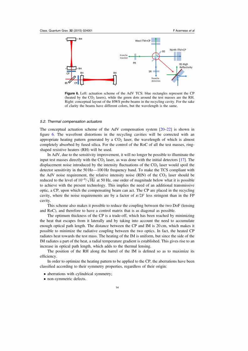
The conceptual actuation scheme of the AdV compensation system [20–22] is shown infigure 6. The wavefront distortions in the recycling cavities will be corrected with anappropriate heating pattern generated by a CO2 laser, the wavelength of which is almostcompletely absorbed by fused silica. For the control of the RoC of all the test masses, ring-shaped resistive heaters (RH) will be used.
In AdV, due to the sensitivity improvement, it will no longer be possible to illuminate theinput test masses directly with the CO2 laser, as was done with the initial detectors [17]. Thedisplacement noise introduced by the intensity fluctuations of the CO2 laser would spoil thedetector sensitivity in the 50 Hz—100 Hz frequency band. To make the TCS compliant withthe AdV noise requirement, the relative intensity noise (RIN) of the CO2 laser should bereduced to the level of −10 Hz8 at 50 Hz, one order of magnitude below what it is possibleto achieve with the present technology. This implies the need of an additional transmissiveoptic, a CP, upon which the compensating beam can act. The CP are placed in the recyclingcavity, where the noise requirements are by a factor of π F2 less stringent than in the FPcavity.
This scheme also makes it possible to reduce the coupling between the two DoF (lensingand RoC), and therefore to have a control matrix that is as diagonal as possible.
The optimum thickness of the CP is a trade-off, which has been reached by minimizingthe heat that escapes from it laterally and by taking into account the need to accumulateenough optical path length. The distance between the CP and IM is 20 cm, which makes itpossible to minimize the radiative coupling between the two optics. In fact, the heated CPradiates heat towards the test mass. The heating of the IM is uniform, but since the side of theIM radiates a part of the heat, a radial temperature gradient is established. This gives rise to anincrease in optical path length, which adds to the thermal lensing.
The position of the RH along the barrel of the IM is defined so as to maximize itsefficiency.
In order to optimize the heating pattern to be applied to the CP, the aberrations have beenclassified according to their symmetry properties, regardless of their origin:
• aberrations with cylindrical symmetry;• non-symmetric defects.
Figure 6. Left: actuation scheme of the AdV TCS: blue rectangles represent the CP(heated by the CO2 lasers), while the green dots around the test masses are the RH.Right: conceptual layout of the HWS probe beams in the recycling cavity. For the sakeof clarity the beams have different colors, but the wavelength is the same.
Class. Quantum Grav. 32 (2015) 024001 F Acernese et al
14
Studies relating to the optimization of the heating pattern have been carried out with afinite element model (FEM). For those aberrations with cylindrical symmetry, the modelinghas shown that the optimum heating pattern [22] would reduce the residual coupling losses toabout 6 ppm (about 0.1 nm rms), thus leading to a reduction factor of about 105, with about18W of CO2 power falling on the CP.
For the non-symmetric optical defects, full 3D modelling is required, making this kind ofsimulation rather computationally expensive. The results of the optimization procedure showthat, by depositing heat in the right CP positions, the residual optical path length rms can bereduced by a factor of 20 for spatial frequencies below 40 m−1 [22] and amounts to 0.35 nm,well within the requirements. The method selected to generate this heating pattern is based ona CO2 laser scanning system. This technique, developed at MIT [23], comprises a pair ofgalvanometer mirrors, to move the laser beam on the surface of the CP, and an acousto-opticmodulator to modify the power content of the beam.
5.3. Sensing for thermal compensation
Aberrations in the recycling cavity optics will be sensed by several complementary techni-ques. The amplitude of the optical path length increase will appear in some ITF channels, aswill the power stored in the RF sidebands. These are scalar quantities that can only give ameasurement of the amount of power scattered into higher order modes. Furthermore, phasecameras [24, 25] will sense the intensity distribution and phase of the fields in the recyclingcavity (carrier and sidebands).
Each optic with a significant thermal load will be independently monitored. The HR faceof each test mass will be monitored in off-axis reflection for deformation. The input testmass/CP phase profile will be monitored on an on-axis reflection from the recycling-cavityside. The TCS control loop will then use a blend of all of the signals from the differentchannels.
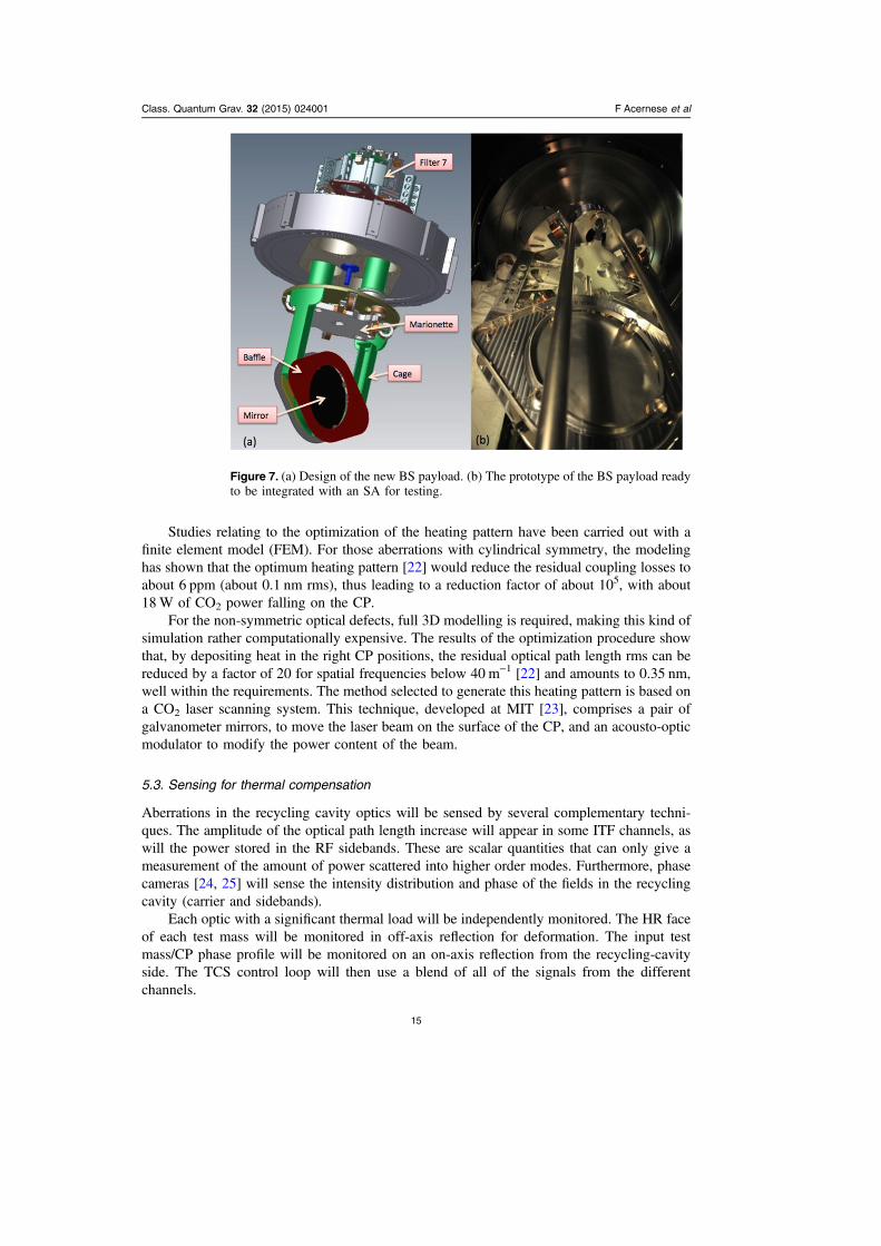
Figure 7. (a) Design of the new BS payload. (b) The prototype of the BS payload readyto be integrated with an SA for testing.
Class. Quantum Grav. 32 (2015) 024001 F Acernese et al
15

The TCS sensors, dedicated to the measurement of thermally induced distortions, consistof a Hartmann wavefront sensor (HWS), and a probe beam (at a different wavelength tothe ITF beam), the wavefront of which contains the thermal aberration information to besensed.
The Hartmann sensor selected for AdV has already been developed and characterized ontest bench experiments and in the Gingin High Optical Power Test Facility for the mea-surement of wavefront distortion [26]. This sensor has been demonstrated to have a shot-to-shot reproducibility of λ/1450 at 820 nm, which can be improved to λ/15500 with averaging,and with an overall accuracy of λ/6800 [27].
The conceptual layout of the HWS beams in the recycling cavity is shown in figure 6. Inthe picture, the beams have different colors for the sake of clarity; the wavelength is the samefor both beams. The beams will be injected/extracted from the injection and detection sus-pended benches and superposed on to the main ITF beam with a dichroic mirror at the level ofthe MMT. This scheme allows for on-axis double pass wavefront measurement (whichincreases the signal-to-noise ratio by a factor of two) and makes it possible to probe all of theoptics in the recycling cavity.
Additional optics are necessary to fulfil the main optical requirements for HWS beams: toimage a plane around the IM HR surface on the Hartmann plate, to illuminate the IM with a10 cm sized Gaussian beam and to match the optimal beam size on the sensor. The twosensing beams are separated by the BS HR coating. The beam from the detection bench willalso sense the BS thermal lensing, thus allowing for its correction on the north arm CP.
6. Mirror suspensions
The mirror is suspended by four wires from a metal body (the marionette), which is moved byan array of coil-magnet actuators to control the position of the mirror itself. The marionette issuspended by a central maraging steel wire from the last filter in the SA chain, named Filter 7.Control forces can be exerted from Filter 7 on both the marionette and the mirror. Thissystem, consisting of mirror, marionette, associated suspensions and actuators, is referred toas the payload. In AdV additional components requiring seismic isolation or control must alsobe suspended from the payload: baffles, CP and RH. Though the design concept is the samefor all of the payloads, the details are different, depending on the components to be suspendedand the size of the mirror.
6.1. Tests on the BS payload
The payload for the BS (see figure 7) was the first to be produced and has been used as a testbench for the adopted design. Following a first assembly for mechanical tests, the BS payloadwas suspended from an SA, and a series of tests were performed.
• Controllability: using optical levers we controlled the position of both the mirror and themarionette, checking the recoil on the actuation cage by means of the sensors dedicatedto the last seismic filter, where the cage is fixed. Concerning the use of the smallermagnets adopted for AdV, a first test of hierarchical control of the payload wasperformed successfully. Namely, using the available actuators and control bandwidthscompatible with those foreseen for AdV, the position accuracy of the baffles and that ofthe mirror were compatible with the operation requirements.
• Pendulum Q: the upper stage of the mirror suspension, the marionette, was optimized inorder to minimize related dissipations. Q values of ×2 104 have been achieved.
Class. Quantum Grav. 32 (2015) 024001 F Acernese et al
16
• Coupling with electro-magnetic stray fields: a detailed electromagnetic FEM wasdeveloped and a measurements campaign was carried out on the BS payload, to tune themodel and to further develop it for the next payloads. To this purpose, the response of theBS payload to a variable magnetic field, produced by a large coil in its proximity, wasmeasured, with the goal of possibly mitigating the eddy current effects induced in theconductive parts of the payload. In addition, the experimental results have been used topredict the influence of measured environmental magnetic noise on the BS. No relevantcontribution to the sensitivity curve is due to magnetic noise on this payload.
6.2. The IM payload
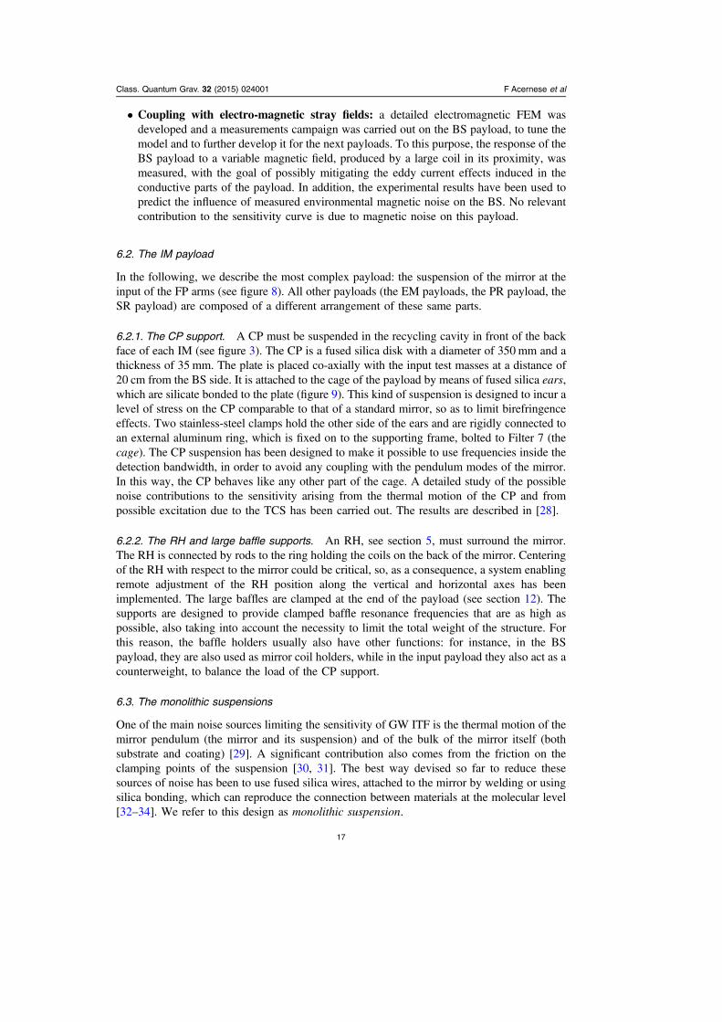
In the following, we describe the most complex payload: the suspension of the mirror at theinput of the FP arms (see figure 8). All other payloads (the EM payloads, the PR payload, theSR payload) are composed of a different arrangement of these same parts.
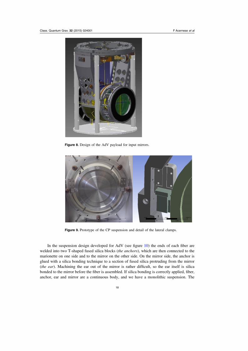
6.2.1. The CP support. A CP must be suspended in the recycling cavity in front of the backface of each IM (see figure 3). The CP is a fused silica disk with a diameter of 350 mm and athickness of 35 mm. The plate is placed co-axially with the input test masses at a distance of20 cm from the BS side. It is attached to the cage of the payload by means of fused silica ears,which are silicate bonded to the plate (figure 9). This kind of suspension is designed to incur alevel of stress on the CP comparable to that of a standard mirror, so as to limit birefringenceeffects. Two stainless-steel clamps hold the other side of the ears and are rigidly connected toan external aluminum ring, which is fixed on to the supporting frame, bolted to Filter 7 (thecage). The CP suspension has been designed to make it possible to use frequencies inside thedetection bandwidth, in order to avoid any coupling with the pendulum modes of the mirror.In this way, the CP behaves like any other part of the cage. A detailed study of the possiblenoise contributions to the sensitivity arising from the thermal motion of the CP and frompossible excitation due to the TCS has been carried out. The results are described in [28].
6.2.2. The RH and large baffle supports. An RH, see section 5, must surround the mirror.The RH is connected by rods to the ring holding the coils on the back of the mirror. Centeringof the RH with respect to the mirror could be critical, so, as a consequence, a system enablingremote adjustment of the RH position along the vertical and horizontal axes has beenimplemented. The large baffles are clamped at the end of the payload (see section 12). Thesupports are designed to provide clamped baffle resonance frequencies that are as high aspossible, also taking into account the necessity to limit the total weight of the structure. Forthis reason, the baffle holders usually also have other functions: for instance, in the BSpayload, they are also used as mirror coil holders, while in the input payload they also act as acounterweight, to balance the load of the CP support.
6.3. The monolithic suspensions
One of the main noise sources limiting the sensitivity of GW ITF is the thermal motion of themirror pendulum (the mirror and its suspension) and of the bulk of the mirror itself (bothsubstrate and coating) [29]. A significant contribution also comes from the friction on theclamping points of the suspension [30, 31]. The best way devised so far to reduce thesesources of noise has been to use fused silica wires, attached to the mirror by welding or usingsilica bonding, which can reproduce the connection between materials at the molecular level[32–34]. We refer to this design as monolithic suspension.
Class. Quantum Grav. 32 (2015) 024001 F Acernese et al
17
In the suspension design developed for AdV (see figure 10) the ends of each fiber arewelded into two T-shaped fused silica blocks (the anchors), which are then connected to themarionette on one side and to the mirror on the other side. On the mirror side, the anchor isglued with a silica bonding technique to a section of fused silica protruding from the mirror(the ear). Machining the ear out of the mirror is rather difficult, so the ear itself is silicabonded to the mirror before the fiber is assembled. If silica bonding is correctly applied, fiber,anchor, ear and mirror are a continuous body, and we have a monolithic suspension. The
Figure 8. Design of the AdV payload for input mirrors.
Figure 9. Prototype of the CP suspension and detail of the lateral clamps.
Class. Quantum Grav. 32 (2015) 024001 F Acernese et al
18
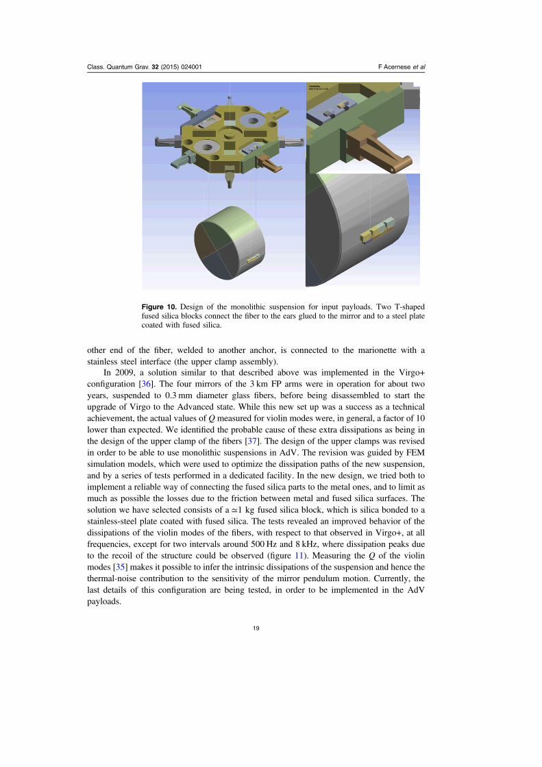
other end of the fiber, welded to another anchor, is connected to the marionette with astainless steel interface (the upper clamp assembly).
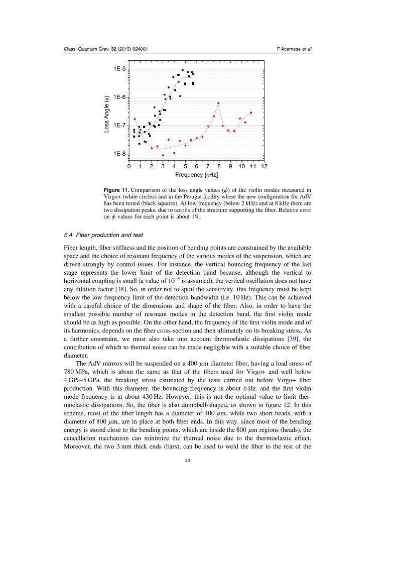
In 2009, a solution similar to that described above was implemented in the Virgo+configuration [36]. The four mirrors of the 3 km FP arms were in operation for about twoyears, suspended to 0.3 mm diameter glass fibers, before being disassembled to start theupgrade of Virgo to the Advanced state. While this new set up was a success as a technicalachievement, the actual values of Q measured for violin modes were, in general, a factor of 10lower than expected. We identified the probable cause of these extra dissipations as being inthe design of the upper clamp of the fibers [37]. The design of the upper clamps was revisedin order to be able to use monolithic suspensions in AdV. The revision was guided by FEMsimulation models, which were used to optimize the dissipation paths of the new suspension,and by a series of tests performed in a dedicated facility. In the new design, we tried both toimplement a reliable way of connecting the fused silica parts to the metal ones, and to limit asmuch as possible the losses due to the friction between metal and fused silica surfaces. Thesolution we have selected consists of a ≃1 kg fused silica block, which is silica bonded to astainless-steel plate coated with fused silica. The tests revealed an improved behavior of thedissipations of the violin modes of the fibers, with respect to that observed in Virgo+, at allfrequencies, except for two intervals around 500 Hz and 8 kHz, where dissipation peaks dueto the recoil of the structure could be observed (figure 11). Measuring the Q of the violinmodes [35] makes it possible to infer the intrinsic dissipations of the suspension and hence thethermal-noise contribution to the sensitivity of the mirror pendulum motion. Currently, thelast details of this configuration are being tested, in order to be implemented in the AdVpayloads.
Figure 10. Design of the monolithic suspension for input payloads. Two T-shapedfused silica blocks connect the fiber to the ears glued to the mirror and to a steel platecoated with fused silica.
Class. Quantum Grav. 32 (2015) 024001 F Acernese et al
19
6.4. Fiber production and test
Fiber length, fiber stiffness and the position of bending points are constrained by the availablespace and the choice of resonant frequency of the various modes of the suspension, which aredriven strongly by control issues. For instance, the vertical bouncing frequency of the laststage represents the lower limit of the detection band because, although the vertical tohorizontal coupling is small (a value of 10−3 is assumed), the vertical oscillation does not haveany dilution factor [38]. So, in order not to spoil the sensitivity, this frequency must be keptbelow the low frequency limit of the detection bandwidth (i.e. 10 Hz). This can be achievedwith a careful choice of the dimensions and shape of the fiber. Also, in order to have thesmallest possible number of resonant modes in the detection band, the first violin modeshould be as high as possible. On the other hand, the frequency of the first violin mode and ofits harmonics, depends on the fiber cross-section and then ultimately on its breaking stress. Asa further constraint, we must also take into account thermoelastic dissipations [39], thecontribution of which to thermal noise can be made negligible with a suitable choice of fiberdiameter.
The AdV mirrors will be suspended on a μ400 m diameter fiber, having a load stress of780MPa, which is about the same as that of the fibers used for Virgo+ and well below4 GPa–5 GPa, the breaking stress estimated by the tests carried out before Virgo+ fiberproduction. With this diameter, the bouncing frequency is about 6 Hz, and the first violinmode frequency is at about 430 Hz. However, this is not the optimal value to limit ther-moelastic dissipations. So, the fiber is also dumbbell-shaped, as shown in figure 12. In thisscheme, most of the fiber length has a diameter of μ400 m, while two short heads, with adiameter of μ800 m, are in place at both fiber ends. In this way, since most of the bendingenergy is stored close to the bending points, which are inside the μ800 m regions (heads), thecancellation mechanism can minimize the thermal noise due to the thermoelastic effect.Moreover, the two 3 mm thick ends (bars), can be used to weld the fiber to the rest of the
Figure 11. Comparison of the loss angle values (ϕ) of the violin modes measured inVirgo+ (white circles) and in the Perugia facility where the new configuration for AdVhas been tested (black squares). At low frequency (below 2 kHz) and at 8 kHz there aretwo dissipation peaks, due to recoils of the structure supporting the fiber. Relative erroron ϕ values for each point is about 1%.
Class. Quantum Grav. 32 (2015) 024001 F Acernese et al
20

suspension and, also, to set the bending point on the right position with respect to the mirrorand the marionette. In any case, these regions must not be longer than a few millimeters, tolimit the bending energy stored there and to make the bending point position independent ofthe welding shape. A FEM, implemented by a specifically developed code [40], was used tosimulate the elastic behavior and to estimate the thermal noise.
Each fused silica fiber is produced starting from commercially available, 10 cm long and3 mm thick, high-purity fused silica cylindrical bars (suitable materials are Herasil orSuprasil). This small cylindrical bar is clamped at both ends and heated in the central regionusing a 200W CO2 commercial laser with a μ10.6 m wavelength. Subsequently, the two endsare pulled apart, extending the fiber to the desired length and shape. This process is performedby a dedicated machine developed at the University of Glasgow and duplicated in Virgo andfurther modified to improve the laser focusing.
Following production, the fibers are tested to a load at least double the operation load.Then, if the fiber survives, its bending length is measured. The bending length λ of thesuspension is the distance of the fiber bending point from the clamped end. Positioning thebending point on the center of mass plane of both the marionette and the mirror allowsminimum coupling between the different DoF.
After this validation, the fibers are then placed in position, clamping the upper part to themarionette and inserting the lower anchor below the lateral supports bonded to the mirror. Inthe end the anchor and the supports are bonded together with silicate bonding.
6.5. Payload assembly and integration
As soon as the silica bonding is cured, the monolithic suspensions are integrated with the restof the mechanical elements described above. The complete payload is inserted into a con-tainer with controlled humidity and cleanliness and transported into the clean room under thetower, which is a vacuum chamber surrounding the SA chain. During transport there iscontinuous monitoring of many physical parameters, such as acceleration, temperature andhumidity. The actual suspension of the mirror at the end of the SA chain requires severalhours of work.
7. Mirror isolation and control
The seismic isolation of the AdV mirrors will be achieved by the SA, a hybrid(passive–active) attenuation system, capable of reducing seismic noise by more than 10 ordersof magnitude in all six DoF above a few Hz. A detailed description of the SA and itsperformance are given in [41].
Figure 12. A sketch of the fused silica fiber shape in AdV.
Class. Quantum Grav. 32 (2015) 024001 F Acernese et al
21

7.1. Mechanics
Since the performance of the SA measured in Virgo is compliant with the AdV requirements,no major changes in the mechanical design have been introduced.
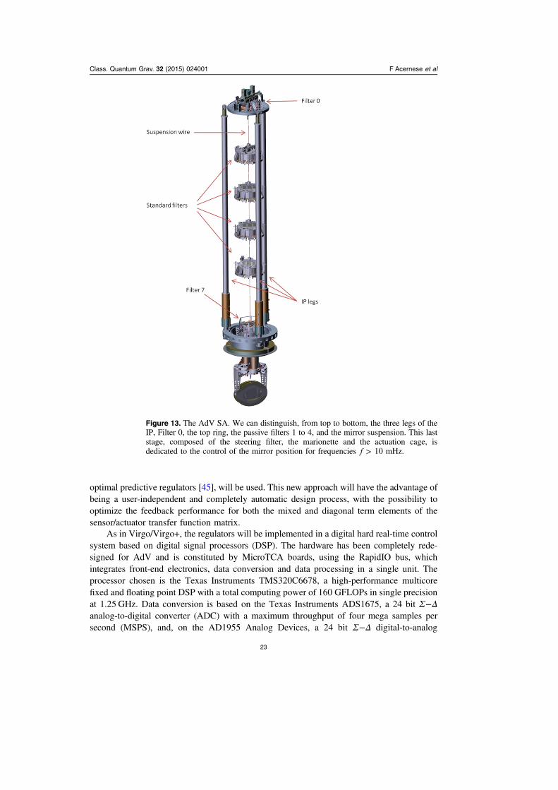
The AdV SA mechanical structure, shown in figure 13, consists of three fundamentalparts:
• the inverted pendulum (IP);• the chain of seismic filters;• the mirror suspension.
The IP [42] consists of three 6 m long aluminum monolithic legs, each connected toground through a flexible joint and supporting an inter-connecting structure (the top ring) onits top. The top ring, which is a mechanical support for an additional seismic filter, is calledFilter 0 and is similar to those used in the chain. It is equipped with a set of sensors andactuators, which are placed in a pinwheel configuration and which are used to actively dampthe IP resonance modes. Two kinds of sensors specifically designed for Virgo/Virgo+, areused: three linear variable differential transformers (LVDT), with a sensitivity of −10 m Hz8
above 100 mHz; and five accelerometers, three horizontal and two vertical, with a sensitivityof × − −3 10 m s Hz10 2 below a few Hz [43]. Two sets of actuators, coil-magnets and motor-springs, are also installed on the top ring.
The chain of seismic filters is suspended from Filter 0 and is composed of an 8 m long setof five cylindrical passive filters, each one designed to reduce the seismic noise by 40 dB bothin the horizontal and vertical DoF, starting from a few Hz.
The payload is suspended from the last seismic filter of the chain, called Filter 7 or thesteering filter. Given that in AdV, as described in section 6, the last stage of the SA has beencompletely redesigned, several changes have been introduced in the mechanics of the Filter 7.In order to keep the same total weight for the payload–Filter 7 assembly, the steering filterssupporting the FP and SR test masses are now 55 kg lighter than in Virgo/Virgo+. The massreduction has been obtained by using a shorter drum steel structure for the filter body and alighter crossbar, which is the mechanical structure designed to support the permanent magnetsused to lower the vertical resonance frequency of the standard filters. Furthermore, six LVDTand six coil-magnet actuators are now installed in a pinwheel configuration on the ringsurrounding the Filter 7, in order to control its motion in all DoF.
7.2. SA control system
As, between 200 mHz and 2 Hz, seismic noise is amplified by the resonance modes of theisolation stages, active control of the SA is needed. As in Virgo/Virgo+, the system has beendesigned using a hierarchical strategy, regulated by the dynamic range of the actuators. In theultra-low frequency band ( <f 10 mHz), actuation will be performed on the IP top stage alongthe z, x, and θy DoF (as is customary, we consider z to be aligned with the suspended mirroroptical axis) using three coils, placed in pinwheel configuration on the top ring. In the 10 mHz< <f 1 Hz band, the control will act both on Filter 7, along six DoF using six actuators, andon the marionette along four DoF (z, θx, θy, θz) using eight coils. For frequencies higher than afew Hz, the force will be applied directly to the mirror along z, using four coils mounted onthe actuation cage, which also allow for tiny corrections along θx and θ .y
In Virgo/Virgo+, the controllers were designed using classical Nyquist-like techniques,diagonalizing the sensor–actuator space with static matrices in order to obtain a set of single-input single-output (SISO) systems [44]. In AdV, a multivariable design approach, based on
Class. Quantum Grav. 32 (2015) 024001 F Acernese et al
22
optimal predictive regulators [45], will be used. This new approach will have the advantage ofbeing a user-independent and completely automatic design process, with the possibility tooptimize the feedback performance for both the mixed and diagonal term elements of thesensor/actuator transfer function matrix.
As in Virgo/Virgo+, the regulators will be implemented in a digital hard real-time controlsystem based on digital signal processors (DSP). The hardware has been completely rede-signed for AdV and is constituted by MicroTCA boards, using the RapidIO bus, whichintegrates front-end electronics, data conversion and data processing in a single unit. Theprocessor chosen is the Texas Instruments TMS320C6678, a high-performance multicorefixed and floating point DSP with a total computing power of 160 GFLOPs in single precisionat 1.25 GHz. Data conversion is based on the Texas Instruments ADS1675, a 24 bit Σ Δ−analog-to-digital converter (ADC) with a maximum throughput of four mega samples persecond (MSPS), and, on the AD1955 Analog Devices, a 24 bit Σ Δ− digital-to-analog
Figure 13. The AdV SA. We can distinguish, from top to bottom, the three legs of theIP, Filter 0, the top ring, the passive filters 1 to 4, and the mirror suspension. This laststage, composed of the steering filter, the marionette and the actuation cage, isdedicated to the control of the mirror position for frequencies >f 10 mHz.
Class. Quantum Grav. 32 (2015) 024001 F Acernese et al
23
converter (DAC), which can process both pulse code modulation (PCM) and direct streamdigital (DSD) data formats. The maximum sampling frequency that can be implemented onthe control system is 640 kHz. A series of multi-channel low-noise power amplifiers, knownsimply as coil drivers, are used to drive the coil-magnet pairs installed on the SA. Every coildriver has an on-board DSP and two distinct sections, each driven by an independent DACchannel: one HP section used for the lock acquisition of the ITF optical cavities, and one low-noise section for linear regime. In this latter mode, the coil drivers can supply up to 0.5 A witha few of pA/ Hz of noise. Each suspension will be typically connected to twenty boards,each hosting a TMS320C6678 DSP. The total computing power, in single precision, availablefor the control of the SA and the processing of its signals will be 3.2 TFLOPs.
7.3. Tilt control
We know experimentally that, during earthquakes or poor weather conditions, seismic noisegrows by up to 2 or 3 orders of magnitude in the 100 mHz—1 Hz band, with a maximum (themicro-seismic peak) between 400 mHz and 500 mHz. Since the ground tilt is transmittedwithout any attenuation at the SA top stage, we estimate that, in these conditions, the angularcomponent of the seismic noise can reach levels high enough to compromise the duty cycle ofthe ITF. A tilt control of the SA will therefore be implemented in AdV.
To this purpose, a set of piezo-electric actuators (Physik Instrumente P-239.30), capableof providing a force of 4500 N with a dynamic range of 40 μm, are installed within the feetsupporting the IP bottom ring. Three LVDT, which monitor the vertical displacement of thering, are used in a closed loop with the piezos in order to increase the linearity of theactuators.
At the same time, a sensor capable of providing tilt measurements that are uncontami-nated by translational components is required to implement a tilt control of the suspension, asthe SA accelerometers produce a signal proportional to a linear combination of horizontalacceleration and tilt. While several studies on mechanical gyroscopes with high sensitivity atlow frequencies have been performed [46, 47], the most promising angular sensor candidatein terms of angle/acceleration cross-coupling is the hemispherical resonator gyroscope (HRG)[48, 49, 50]. An HRG, custom-made by the Russian firm MEDICON for AdV, is currentlybeing tested.
8. Laser
8.1. Overview
The AdV laser source is an HP continuous-wave laser, which is stabilized in frequency,intensity and beam pointing. The HP requirement is necessary to overcome the shot-noiselimit, while the stabilization brings the technical noises of the laser down to a level where theyno longer mask the tiny GW signal. A laser power of at least 175W in TEM00 mode isrequired to meet the sensitivity goal. In the absence of a perfect symmetry in the cavities, theinterference between the two arms of the Michelson reflects all of the frequency and powerfluctuations of the laser. In order to detect such a small GW signal as 10−23 in relative strain,the relative frequency and power fluctuations of the laser have to adhere to the same order ofmagnitude. Then, for a laser light emitting at a 1 μm wavelength, we end up with a fewμHz Hz for the laser frequency fluctuations, while in free-running conditions a quiet laserproduces a noise of a few kHz Hz . This establishes a stabilization factor of nine orders ofmagnitude, which is quite hard to obtain with a single stage of servo-loop. Therefore, a multi-
Class. Quantum Grav. 32 (2015) 024001 F Acernese et al
24
stage servo-loop is then used for the frequency stabilization, with different references, rangingfrom a rigid FP cavity to the arms differential of the Michelson itself. To minimize laserpower fluctuations, the Michelson operates on the dark fringe, but the DC readout methodused in advanced detectors requires a small deviation from the dark fringe. Combined withthe fluctuating radiation-pressure noise suffered by the mirrors, the laser-power fluctuationsmust be in the range of −10 Hz9 , while the beam pointing has to be below 10−11 rad Hz .
8.2. HP laser for AdV
Achieving such HP output with a highly stable laser is a serious challenge, which is managedby separating the two functions of HP output and stabilization: a low-power stable laser isused to transfer its stability to a HP oscillator by injection-locking and/or amplifying itthrough an internal laser process, helped by a slow servo-loop to prevent drifts. While, in thefirst case, the stable output of the low-power laser is automatically transferred to the HP laser,the amplifier case contains no filtering cavity and transfer of stability is achieved only insaturation regimes. The HP oscillators used so far in Virgo/Virgo+ have been based on Nd:YV04 (neodymium-doped yttrium orthovanadate) crystals, which are the best choice for the100W class lasers. The first phase of the AdV project requires a medium-power laser ofaround 35W–40W at the input of the mode cleaner, while the final phase will need about200W output, such that at least 175W in TEM00 mode can be delivered as requested. Themedium-power laser is today an Nd:YVO4 oscillator amplifying a 20W injection-lockedlaser to deliver around 60W. The free-running frequency noise of this amplifier copies that ofthe master laser, which is a monolithic, commercial non-planar ring oscillator of 1W(Innolight NPRO). Though intrinsically stable in the short term, it will nevertheless befrequency stabilized to the Michelson arms.
To reach the ultimate power we plan to use amplifiers based on fiber technology. AnR&D project is in progress with the goal of delivering the final laser for installation in 2018.
8.3. Stabilization of the HP laser
8.3.1. Frequency stabilization. The frequency stabilization acts on the piezo transducer of themaster laser. The error signal is a combination derived from a multi-stage servo-loop, using asreferences: the rigid reference cavity (RC), the IMC and the differential arms of theMichelson.
8.3.2. Power stabilization of the laser. Comparing the light power fluctuations to a stablevoltage gives the error signal, which is fed back to the HP amplifier pumping diode current forthe power stabilization. The principle sounds simple, but a voltage fluctuation measured outof a photodiode can contain not only the light fluctuations, but also any other fluctuation dueto surface inhomogeneity (e.g. air pressure fluctuations, dust crossing the beam). Therefore, acareful selection of photodiodes has to be made, and these must be used in a quietenvironment, such as under a vacuum. Furthermore, we know that resonant cavities act aslow-pass first-order filters for laser amplitude and beam-jitter noise. For amplitude noise, thecorner frequency of this filtering is equal to half the line-width of the cavity. Therefore,placing the power-stabilization photodiode under a vacuum after the IMC relaxes theconstraints of the servo-loop in the MHz range and, in our case, amplitude and beam-jitternoises begin to be attenuated by the IMC above 800 Hz–900 Hz. Nevertheless, a powerstabilization servo-loop is still necessary inside the detection range, mostly below 500 Hz.The photodiodes have been designed to fulfil the specifications, i.e. an RIN of
Class. Quantum Grav. 32 (2015) 024001 F Acernese et al
25

× −1.2 10 Hz9 at the frequency of 30 Hz, which is the most stringent requirement. To reachthis level of stabilization, the required shot-noise limit on the photodiodes has to be lowerthan −10 Hz9 , which requires an equivalent of about 400 mA. Due to the limited standingpower of fast photodiodes, the light sensor is composed of two sets of two photodiodessharing a total amount of 400 mA of photocurrent. Two photodiodes are coherently combinedand provide a measured noise floor limit of × −1.3 10 Hz9 with a 400 mA photocurrent.The two others will be used for out-of-loop verification.
8.3.3. Laser beam shape and jitter control. The last control of the laser beam concerns thebeam shape and the beam pointing noise. To lower the beam noise at the entrance of theinjection bench and to filter out the high order modes inherent to HP lasers, a pre-mode-cleaner (PMC) is positioned on the laser bench. A compromise has been found for itsspecifications between the finesse and the high level of stored light in a small beam waist. Toavoid direct feedback to the laser, the PMC is a triangular non-monolithic cavity, whichcarries a piezo transducer to control its length relative to the laser frequency. This PMC hasalready been used for the Virgo+ phase and was able to work with a 50W laser, with a finesseof 500 in a beam of 500 μm. It is useful to remember that the PMC lies on a horizontal planeand therefore reduces the horizontal beam jitter.
9. Light injection
9.1. Overview
Figure 14 shows an overview of the input optics found between the laser and the interferomerand designed to provide a beam with the required power, geometrical shape, frequency andangular stability. The main requirements for the input optics are:
• transmission to the ITF >70% TEM00;• non-TEM00 power <5%;• intensity noise × −2 10 9/ Hz at 10 Hz;• beam jitter < −10 10 rad/ Hz ( >f 10 Hz);• frequency noise (for lock acquisition) <1 Hz rms.
An electro-optic modulation (EOM) system provides the RF phase modulations neededfor the ITF cavity control. A system based on piezo actuators and DC quadrant photodiodes,the beam pointing control (BPC) system, has been developed to reduce, as much as possible,low-frequency beam jitter before it enters the vacuum system. Another system (EIB–SAS)reduces the beam jitter induced by the structural resonances of the optical-bench legs. Apower-adjustment system (input power control), consisting of a half waveplate and a fewpolarizers, is then used to tune the ITF input power. Some matching and steering of in-airoptics is required to properly couple the beam with the in-vacuum suspended IMC cavity. TheIMC geometrically cleans the beam and reduces its amplitude and beam-pointing fluctuationsbefore the ITF. The resonant IMC, the length of which is locked on the RC, serves as a firststage of frequency stabilization for the main laser. After the IMC, an intensity-stabilizationsection provides the signal for stabilizing the laser RIN and thus to reach the requirements.Then, an in-vacuum FI prevents interaction between the ITF rejected light and the IMC andlaser system. Finally, an MMT (the ITF MMT) is used to match the laser beam to the ITF.
Class. Quantum Grav. 32 (2015) 024001 F Acernese et al
26

9.2. Electro-optic modulator
In AdV, five different modulation frequencies are required. To create them, we use threecustom modulators, located between the laser system and the vacuum vessel on the externalinjection bench (EIB). Because of the high input laser power, we have selected a lowabsorption electro-optic material: the RTP (rubidium tantanyle phosphate RbTiOPO4) fromRaicol Crystals. This material has a very low absorption level (<50 ppm cm−1 @ 1064 nm),thus reducing the thermal-lensing effects. In fact, a thermal focal length of ∼10 m for 200Wof input optical power has been measured for each modulator. Each crystal surface is wedgedand has a trapezoidal shape. A horizontal wedge of one degree on both sides allows theseparation of the linear polarizations by walk-off. We can also avoid the cavity effect andreduce the residual amplitude modulation (RAM) [51], which could be a source of noise(RAM < −10 6 required). These modulators have been tested in the laboratory and a mod-ulation depth higher than 0.1 has been obtained. They are currently being installed on thedetector. Figure 15 shows a view of one modulator and the spectrum of the laser beam after ithas passed through the modulator.
9.3. BPC system
Beam-pointing fluctuations can be a relevant source of noise. Indeed, in the case of geo-metrical asymmetries between the arms of the ITF, created by spurious misalignments of theITF optics, the input-beam jitter creates a phase noise directly affecting detector sensitiv-ity [52, 53].
The AdV ‘BPC system’ [54] is designed to monitor and mitigate below 10 Hz, the beam-pointing noise at the input of the IMC. It is composed of two quadrant photodiodes, whichsense the input-beam displacement, and two tip/tilt piezoelectric actuators, which compensateit. The sensing design places the two quadrants in the focal and image planes of the input ofthe IMC to, respectively, sense the tilt and the shift of the beam.
The BPC system achieves a control accuracy of ∼ −10 8 rad for the tilt and ∼ −10 7 m forthe shift, along with a sensing noise of less than 1 nrad/ Hz , making it compliant with therequirements.
Figure 14. General input optics scheme.
Class. Quantum Grav. 32 (2015) 024001 F Acernese et al
27

9.4. EIB–SAS
The excess motion of the EIB, due to the seismic excitation of its rigid body modes, can be amajor source of angular and lateral beam jitter in the injection system and thus limit thedetector sensitivity. A new actively controlled bench support system, called the EIB seismicattenuation system (EIB–SAS), has been created to meet the requirement of having a neutralbehavior with respect to the ground motion in a broad frequency range (DC to severalhundreds of Hz). The EIB–SAS (see figure 16) is a single-stage six DoF vibration isolator, thedesign of which is derived from the Advanced LIGO HAM–SAS prototype [55], which hasbeen more recently upgraded and adapted at AEI Hannover, in order to be incorporated intotheir 10 m prototype ITF [56].
Passive seismic attenuation, from 20 dB to 70 dB in the vertical and from 30 dB to 70 dBin the horizontal between 2 Hz and 400 Hz [57], is achieved by means of a combination of ashort (0.5 m long legs) IP and three sets of cantilever blades in geometric anti–spring (GAS)configuration [58]. All six fundamental rigid body modes have natural frequencies tunedbetween 0.2 and 0.5 Hz. The EIB–SAS is equipped with position (LVDT) and inertial(geophones) sensors and voice-coil actuators to actively damp the low-frequency eigenmodesand to stabilize the position and orientation of the supported bench. Higher frequency modes,originating from the GAS spring lateral compliance and from the vertical compliance of the IPstructure, are treated with tuned dampers placed on the spring-box. The internal modes of theIP legs are cured with eddy current dampers. Stepper motor-driven correction springs are usedfor initial (and periodical over the long term) coarse alignment of the bench.
9.5. IMC cavity
The IMC cavity is an in-vacuum, triangular cavity comprising suspended optics, which has alength of 143.424 m and a finesse of 1200 (corresponding to an input/output couplerreflectivity of 2500 ppm, and total round-trip losses lower than 100 ppm). The finesse andlength of the cavity are unchanged with respect to Virgo, as they are still thought to be a goodcompromise when considering the high spatial-filtering effect of the cavity and issues linkedto the high finesse and length, such as radiation pressure, thermal effects and the small angleback-scattering from the EM. On the other hand, stricter polishing requirements have been set
Figure 15. 22 MHz and 56 MHz sidebands, measured with a scanning FP cavity (left);AdV electro-optic modulator and the EIB.
Class. Quantum Grav. 32 (2015) 024001 F Acernese et al
28
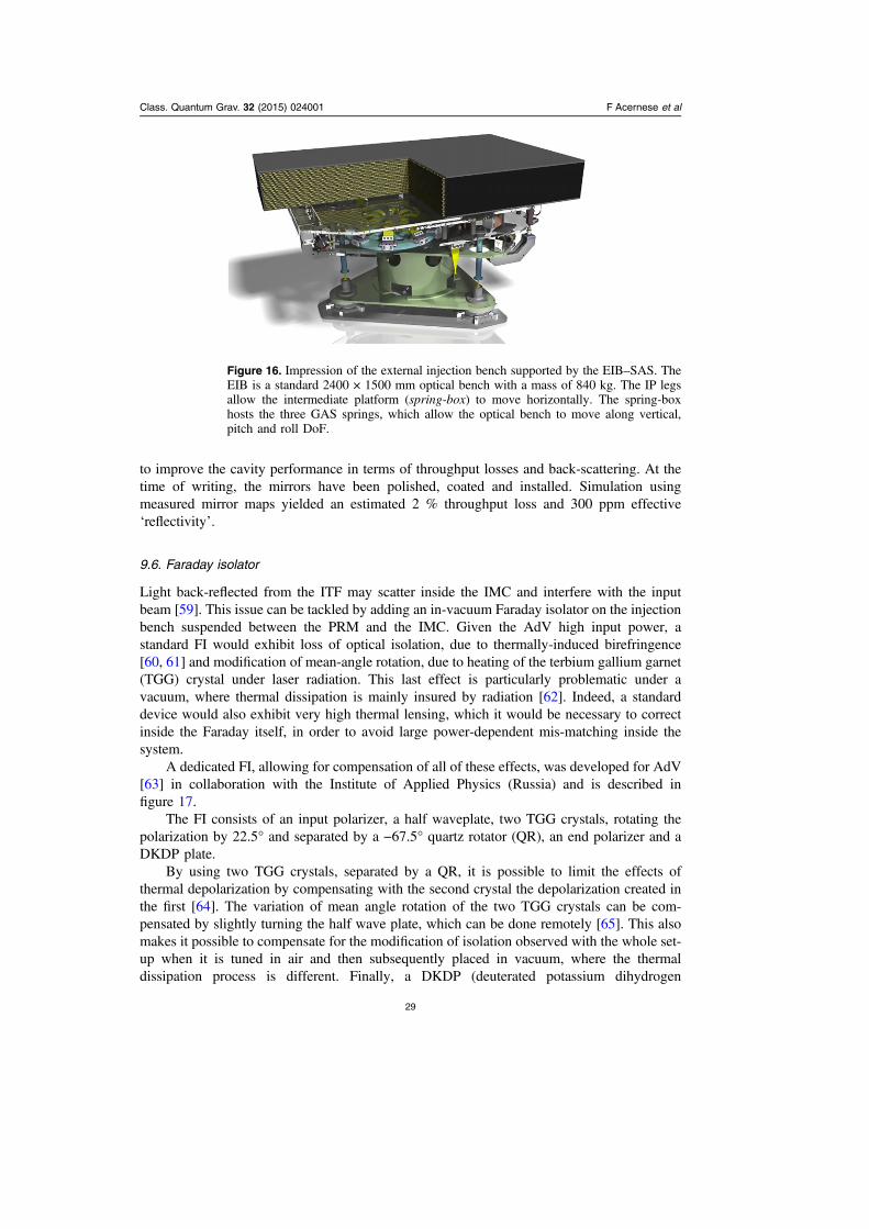
to improve the cavity performance in terms of throughput losses and back-scattering. At thetime of writing, the mirrors have been polished, coated and installed. Simulation usingmeasured mirror maps yielded an estimated 2 % throughput loss and 300 ppm effective‘reflectivity’.
9.6. Faraday isolator
Light back-reflected from the ITF may scatter inside the IMC and interfere with the inputbeam [59]. This issue can be tackled by adding an in-vacuum Faraday isolator on the injectionbench suspended between the PRM and the IMC. Given the AdV high input power, astandard FI would exhibit loss of optical isolation, due to thermally-induced birefringence[60, 61] and modification of mean-angle rotation, due to heating of the terbium gallium garnet(TGG) crystal under laser radiation. This last effect is particularly problematic under avacuum, where thermal dissipation is mainly insured by radiation [62]. Indeed, a standarddevice would also exhibit very high thermal lensing, which it would be necessary to correctinside the Faraday itself, in order to avoid large power-dependent mis-matching inside thesystem.
A dedicated FI, allowing for compensation of all of these effects, was developed for AdV[63] in collaboration with the Institute of Applied Physics (Russia) and is described infigure 17.
The FI consists of an input polarizer, a half waveplate, two TGG crystals, rotating thepolarization by 22.5° and separated by a −67.5° quartz rotator (QR), an end polarizer and aDKDP plate.
By using two TGG crystals, separated by a QR, it is possible to limit the effects ofthermal depolarization by compensating with the second crystal the depolarization created inthe first [64]. The variation of mean angle rotation of the two TGG crystals can be com-pensated by slightly turning the half wave plate, which can be done remotely [65]. This alsomakes it possible to compensate for the modification of isolation observed with the whole set-up when it is tuned in air and then subsequently placed in vacuum, where the thermaldissipation process is different. Finally, a DKDP (deuterated potassium dihydrogen
Figure 16. Impression of the external injection bench supported by the EIB–SAS. TheEIB is a standard 2400 × 1500 mm optical bench with a mass of 840 kg. The IP legsallow the intermediate platform (spring-box) to move horizontally. The spring-boxhosts the three GAS springs, which allow the optical bench to move along vertical,pitch and roll DoF.
Class. Quantum Grav. 32 (2015) 024001 F Acernese et al
29

phosphate, KD2PO4) plate is used to compensate for thermal lensing created inside the TGGcrystals, because of its large negative thermo-optic coefficient [66]. Using this device we canensure an isolation ratio of 40 dB at 150 W, a residual thermal lens as low as 100 m at fullpower and a total transmission of about 98%.
9.7. Mode-matching telescope
The design of the MMT has been driven by the space constraints on the suspended injectionbench (SIB) and the need to limit, as much as possible, the aberrations of the beam [67, 68].The telescope is made by an afocal two-mirror, off-axis parabolic telescope, which increasesthe beam size from 2.6 mm (size of the beam inside the Faraday), to 22 mm (see figure 18).The beam is then expanded by a meniscus lens, and is finally re-collimated by the PRM, theanti-reflecting (AR) coated surface of which is curved, to the FP cavities. The meniscus lens isneeded to compensate for the spherical aberrations of the PRM. This design allows a theo-retical matching of the input beam with the ITF that is higher than 99.9%.
In order to limit the scattered light from the optics, requirements on the surface quality ofthe parabolic mirrors (roughness < 1 nm) and on the AR coating of the meniscus lens(<100 ppm) have been set. In addition, the optical mounts have been designed in order to limitthe presence of low-frequency resonances. Moreover, the telescope is suspended from an SA,limiting the modulation of the scattered light in the AdV detection band by seismic noise.
Figure 17. Left: a scheme of the HP-compatible Faraday isolator. Right: a view of theassembled device.
Figure 18. Catadioptric telescope of the SIB1 layout (left); MMT installed on SIB1(right) in February 2014.
Class. Quantum Grav. 32 (2015) 024001 F Acernese et al
30
The telescope has been installed on the SIB 1 (SIB1) and was pre-aligned at thebeginning of 2014.
10. Light detection
10.1. Overview
The detection system extracts the ITF signals from the anti-symmetric port and from theauxiliary beams. It consists of several optical benches, hosting photodetectors, as well asmotorized alignment optics and MMT. The beam from the anti-symmetric port, referred to asthe dark-fringe beam, carries information about a change in the differential arm-length(DARM) and is thus sensitive to GW. The detection system must comply with the DCdetection scheme. Auxiliary beams are sensitive to other ITF DoF, such as cavity lengths andlaser frequency variations, providing signals needed for the ITF control systems. The opticalbenches designed for the extraction of the main ITF beams are sketched in figure 19(a) anddescribed below.
A first detection bench (SDB1) is placed along the path of the dark-fringe beam. Anoptical layout of SDB1 is presented in figure 19(b). This bench hosts an OMC the goal ofwhich is to improve the contrast defect by filtering out spurious components of the light,which are induced by ITF imperfections. In the DC detection scheme the OMC must alsofilter out the RF sidebands. The SDB1 bench is followed by a second suspended detectionbench (SDB2) which hosts sensors for the detection of the dark fringe beam and secondarybeams involved in the ITF control. Both SDB1 and SDB2 are suspended and placed under avacuum, in order to isolate sensitive optics and photodetectors. An external detection bench(EDB) hosts less-sensitive equipment, such as a phase camera [24] and a HWS which, asexplained in section 7, will be used to monitor the thermal aberrations and optical defects inthe ITF.
A suspended bench denoted as SPRB is used to extract a pick-off beam from the PRcavity. It hosts a telescope to adapt the beam size and Gouy phase to the photodetectors.Similarly a suspended bench equipped with a telescope at the end of each ITF arm (namedSNEB for the north arm and SWEB for the west arm) allows the extraction of the beamtransmitted by the FP cavity. Another suspended bench, named SIB2, extracts the beamreflected by the ITF.
One of the design criteria of the detection system has been the minimization of the impactof stray and scattered light, which was one of the noise sources limiting the sensitivity of thefirst-generation ITF. In order to limit the amount of back-scattered light, stringent require-ments have been set on the micro-roughness (typically ⩽ 0.3 nm rms for spherical and flatoptics, and ⩽ 1 nm rms for the parabolic mirrors of the telescope) and the anti-reflectivecoating (≈ 100 ppm targeted) of the optics placed along the path of the dark-fringe beam.Moreover, scattered-light noise couples through the displacement of the optics, which isamplified at the resonance frequencies of the mounts. Therefore, the main optical benches areseismically and acoustically isolated.
10.2. Suspended detection benches
In addition to SDB1, which is suspended to a short version of the Virgo SA (see section 6),five new benches will be installed in new vacuum chambers and suspended from complexisolation systems. As shown in section 13, the designed vacuum chambers are very compact,which is necessary to comply with the space constraints of the existing infrastructure.
Class. Quantum Grav. 32 (2015) 024001 F Acernese et al
31

Accordingly a compact isolation system (see section 13) and a new suspended bench body[69], which fit in these vacuum chambers, have been designed. A 3D drawing of the benchinside the vacuum chamber is shown in figure 20. The bench body is made of aluminium andincorporates a sealed air container hosting, in particular, electronic boards used for the readoutand control of the sensors located on the bench. This strategy minimizes the number of cablesrunning along the suspension, which helps to keep the isolation system compact, whileavoiding mechanical short-circuiting. As a consequence of having the sensing electronicsintegrated within the bench body, a significant amount of heat has to be dissipated into thevacuum chambers. The heat will be evacuated from the electronic components to the benchbody through conduction, using heat links, and from the bench body to the vacuum chamberwalls through radiation. To this purpose, the suspended bench will be anodized in order tomaximize its thermal emissivity. For the inner part of the stainless-steel chamber, a sand-blasting treatment is enough to provide a sufficiently high thermal transfer, since its surface islarger than the bench external surface.
10.3. Output mode cleaner
The AdV OMC is made of two identical cavities, placed in series [70] (see figure 19(b)). Eachcavity is made of a monolithic block of fused silica with four polished surfaces, whichtogether form a four-mirror bow-tie cavity. The choice of a compact monolithic cavity hasbeen made to minimize the cavity length noise and to keep mechanical resonances above thedetector bandwidth, namely above 10 kHz. The round-trip length (Lrt = 248 mm) and thenominal finesse (F = 143) of the cavity have been chosen to meet the AdV requirements onthe filtering of the RF sidebands for DC detection. Having two cavities in series offers thepossibility of keeping a moderate finesse value, which eases the lock of the cavity and, for agiven locking accuracy, limits the coupling of cavity-length noises, proportional to the squareof the finesse. The finesse has also been chosen sufficiently low to keep the internal losses per
10.510.6
10.710.8
10.911.0
11.111.2
11.311.4
-0.4
-0.5
-0.3
-0.2
-0.1
0.0
0.1
0.2
0.3
0.4
Figure 19. (a) A scheme of the optical benches foreseen for AdV. (b) The optical layoutof the first suspended detection bench SDB1. YAG beams (λ = 1064 nm) are displayedin red. A Hartmann beam (λ = 800 nm) is displayed in green.
Class. Quantum Grav. 32 (2015) 024001 F Acernese et al
32

cavity, expected to be dominated by scattering losses, lower than 1 %. One of the cavitysurfaces is spherical, which makes the cavity stable. The RoC, equal to 1.7 m, has beenchosen to avoid degeneracies between the carrier fundamental mode and the high order modesof the carrier and sidebands, as well as to minimize the cavity thermo-refractive noise, whichis inversely proportional to the square of the cavity waist [71] (the nominal waist is 321 μm).The carrier fundamental mode must be kept resonant in the two OMC cavities, which isachieved by controlling each cavity optical-length with two types of actuators: Peltier cellsand a piezo-electric actuator (PZT). The PZT actuator is also used to modulate the cavitylength. The error signal used to control the cavity length is extracted by demodulating thesignal provided by the photodetectors placed in transmission of the OMC at the PZT mod-ulation frequency. This control system is designed to satisfy the requirements of a lockingaccuracy lower than 1.2× −10 12m.
10.4. Telescopes
Two types of telescopes are needed: an OMC MMT (OMC_MMT) on the SDB1 bench (seefigure 19(b)), and a telescope used to adapt the beam parameters to the photodetectors placedon the end benches (SNEB and SWEB) and pick-off bench (SPRB).
The design of the OMC_MMT is very similar to the injection MMT described insection 9.7. This design has been driven by the space constraints on the SDB1 bench and therequirements on the beam quality to limit aberrations. This telescope consists of a divergingmeniscus lens, used in combination with a curved surface of the SRM, to reduce the size ofthe beam from 49 mm to 22 mm and compensate the spherical aberrations induced by the SRlens. An afocal off-axis telescope, made of two mirrors, is then used to decrease the beam sizeby a factor of 17. Finally, two lenses are used to match the beam to the OMC. Thanks to thisdesign, the theoretical matching of the ITF beam to the OMC is higher than 99.9%.
The telescopes of SNEB, SWEB and SPRB are very similar to those used in Virgo, witha doublet as a main focusing element and a second lens used to tune the Gouy phase on twoquadrant photodiodes.
10.5. Sensors and front-end electronics
Three main types of sensor are used as part of the detection system.
Figure 20. A 3D drawing of the new suspended bench inside its vacuum chamber.
Class. Quantum Grav. 32 (2015) 024001 F Acernese et al
33
• ‘Longitudinal’ photodiodes provide signals that are sensitive to length variations in theITF and, in the case of the photodiodes placed at the dark port, to GW signals.
• Quadrant photodiodes provide signals sensitive to the alignment of the ITF mirrors.• Phase cameras are used to monitor the surface defects of the ITF mirrors.
The main longitudinal and quadrant photodiodes are hosted on the suspendedbenches. Each photodiode is placed inside a sealed-air box, the analog outputs of which areconnected to the suspended bench electronic container through in-vacuum cables andfeedthroughs.
Longitudinal photodiodes. Longitudinal photodiodes are high-quantum-efficiencyInGaAs PIN photodiodes, with clear apertures of 2 mm and 3 mm. The photodiode elec-tronics chain is made of three main parts. First, a preamplifier converts the photodiode currentto voltage and provides channels for different bandwidths: a large-dynamics DC channel to beused up to a few Hz; a highly-sensitive audio channel, high-pass filtered above 5 Hz; and a RFchannel with a high-frequency bandwidth. The RF signal is then digitized by a demodulationboard, which, as explained in section 15, performs the digital demodulation [72] at thefrequencies of the modulation sidebands (ranging from 6MHz to 132MHz) and their doublefrequencies. The audio and DC signals are digitized by a ‘service’ board, which also providesthe bias voltage and monitors the photodiode air box.
With the DC detection scheme, the audio signals of the photodiodes placed at the anti-symmetric port are used to search for GW. Demodulated signals are used as error signals tocontrol the ITF longitudinal DoF and thus their noise can also have an impact on the ITFsensitivity. Accordingly, both RF and audio channels are designed so that their associatedelectronics noise is lower than the photodiode shot noise, by up to a factor of 10 for the audiochannel of the dark fringe.
Quadrant photodiodes. Quadrant photodiodes are Si–PIN diodes, with a 5 mm diametertotal aperture, divided into four sections. By design, these sensors are sensitive to beammisalignments. Two types of electronic configurations are foreseen. Quadrants placed at theSNEB and SWEB terminal benches are optimized for DC sensing: their DC channels, whichare designed to be shot-noise limited, provide error signals involved in the alignment of theFP arm cavities. Quadrants placed on other suspended benches are equipped with a RFchannel, which, after being demodulated at the sideband frequencies, provides error signalsfor the alignment of the other ITF DoF.
Phase cameras. Phase cameras provide wavefront-sensing capabilities to measure thespatial profiles of each frequency component of the laser field (carrier and sidebands).These spatial profiles contain information about mirror-surface defects and can thus beused to determine corrections to be applied to the mirrors. The AdV phase cameras arebased on an optical heterodyne measurement: a reference beam, extracted from the AdVlaser bench, is frequency shifted at 80 MHz by an acousto-optic modulator, and travelsup to the phase camera benches through optical fibers. The reference and test beams arecombined onto a BS and co-propagate towards a detection port of the phase camera.The detection port is made of a pinhole photodiode and a scanning system, making itpossible to scan the wavefront over the pinhole diode. Information on the wavefrontamplitude and phase are then obtained by demodulating the photodiode output at thebeat frequency between the reference beam and the frequency components of the tes-ted beam.
Class. Quantum Grav. 32 (2015) 024001 F Acernese et al
34

11. ITF control
11.1. Steady state
To be able to detect GW, the various cavities of the ITF must all be kept on resonance withpicometer accuracy. To stay at this working point in spite of external disturbances, a high-performing feedback system is needed. This is achieved with a real-time, digital controlsystem (see section 14), which uses the output of various photodiodes (see section 10) as errorsignals and actuates on the mirror position using voice-coils (see section 6). This controlsystem acts on the ITF as a whole, e.g. a signal from the dark fringe photodiode in the CentralBuilding is used to actuate on the end test masses, located 3 km away.
For the control of the ITF, it is common to define five longitudinal DoF, which roughlycorrespond to signals available on the various photodiodes:
• The differential length of the two 3 km long arm cavities (DARM). This is the mostimportant DoF, since it contains the GW signal. The most sensitive photodiode forcontrolling this DoF is the DC power of the dark fringe (B1). To obtain a proper errorsignal, the DARM DoF needs to be moved away from the dark fringe position by someten picometers. This scheme is known as DC-detection [73]. To filter out thedemodulation sidebands, this beam is first passed through the OMC. This DoF iscontrolled by actuating differentially on the two end test masses.
• The common length of the two arm cavities (CARM). A demodulated signal in reflectionof the ITF is used as an error signal. Instead of actuating mechanically on some mirrors,this DoF is controlled by actuating with high bandwidth on the frequency of the mainlaser. At very low frequencies, this frequency is stabilized on a monolithic RC, byactuating in a common way on the end test masses.
• The differential length of the short Michelson ITF, formed between the BS and the twoinput test masses (MICH). As an error signal, a demodulated signal from the pick-offbeam taken inside the PR cavity is used. Actuation is performed on a combination ofvarious mirrors.
• The length of the PR cavity (PRCL), which is the cavity between the PRM and the twoinput test masses. As error signal, a demodulated signal in reflection of the ITF is used,while the actuation is performed on the PRM only.
• The length of the SR cavity (SRCL), which is the cavity formed between the SRM andthe two input test masses. As error signal, a demodulated signal from the pick-off beam isused, while the actuation is performed on the SRM only.
For most of these DoF, the error signals are obtained by a heterodyne scheme similar tothe Pound–Drever–Hall technique. To this end, modulation sidebands at 6, 8 and 56 Mhz areadded to the laser in the injection system (see section 9). The first four of these DoF were alsoused in Virgo+, in a configuration which is known as a power-recycled ITF. Initially, AdVwill be run in the same configuration. Only in a second step, will the SRM be added, whichadds the new SRCL DoF. This configuration is known as a dual-recycled ITF.
Slightly different photodiodes, demodulation sidebands and demodulation phases areused in the power-recycled and double-recycled configuration. To choose the optimal pho-todiodes for controlling the various DoF, the optical response of the ITF is first simulated inthe frequency domain using Optickle [74]. For each DoF, the photodiode and demodulationphase is chosen, in which a particular DoF is visible with the highest signal-to-noise ratio.Since most photodiodes are sensitive to multiple DoF, the effect of the control system must be
Class. Quantum Grav. 32 (2015) 024001 F Acernese et al
35

taken into account. This whole design is therefore an iterative procedure, in which the variousfeedback loops are optimized until the various accuracy requirements are fulfilled [75].
11.1.1. Noise subtraction. The optical response of the ITF to the various DoF is not adiagonal system, meaning that the main photodiode is not only sensitive to DARM, but alsoto a lesser degree to signals from the other DoF (mainly MICH and SRCL). For this reason,the sensing noise of these auxiliary DoF will also end up in the GW signal. To reduce thiseffect, a noise subtraction technique is used, in which the appropriately filtered actuationsignal of the auxiliary DoF is added to the actuators used for DARM. A subtraction of a factorof 500 has been achieved in the past [76]. A similar subtraction factor will be needed forAdV, in order not to spoil the sensitivity at low frequencies. A similar noise-subtractiontechnique is used when reconstructing the h(t) signal used in data analysis [77].
11.2. Lock acquisition
When all cavities are on resonance, the optical response of the ITF acts like a linear system.This allows for the design of a robust control system using standard techniques, which cankeep the ITF locked for many hours, failing only in the case of large external disturbances,such as earthquakes. Bringing the ITF to this working point, however, requires a complexprocedure, since the uncontrolled mirrors initially swing with large amplitude, causingcomplex non-linear transient signals. The procedure to get from this uncontrolled state to thefinal working point, ready to collect science data, is called the lock acquisition. Developingthis procedure is achieved with the help of time-domain simulation tools, such as E2 E [78]. Atypical lock acquisition consists of many steps, in which the control of the various DoF ishanded from one photodiode to another.
In the past, with the Virgo+ ITF, this was achieved with a deterministic procedure calledthe variable finesse technique [79]. In this procedure, the ITF is initially locked with theMICH DoF at half fringe and the PRM misaligned. After aligning this mirror, MICH isbrought gradually towards the dark fringe, which allows for a controlled build-up of thepowers inside the cavities. Since AdV will initially start without an SRM, the optical schemeis very similar, so we will use the same procedure. The main difference is that at the end, thelock of DARM will change from a demodulated to a DC signal.
The SRM will be installed only in a second stage, which adds a fifth DoF to be con-trolled: SRCL. Developing a lock-acquisition procedure that only uses standard photodiodesignals has been shown to be very difficult [80]. To solve this issue, an auxiliary laser systemoperating at a wavelength of 532 nm was developed at LIGO, which can measure the arm-cavity lengths independently of any other DoF [81]. For AdV, we plan to implement a similarsystem. This system is still being developed, but the coatings of the main mirrors have alreadybeen designed to take the extra wavelength into account.
11.3. Angular control
Apart from the longitudinal DoF, there are also the two angular DoF of each mirror, to becontrolled with nano-radian accuracy [82]. For this reason a global angular control system,the automatic alignment (AA), which uses the signals coming from the ITF itself, is required.
The implementation of the angular control for AdV will have to face a more complexconfiguration with respect to that of Virgo [83, 84]. The main differences between the AdVand Virgo ITF configurations are the higher circulating power and the presence of the SR
Class. Quantum Grav. 32 (2015) 024001 F Acernese et al
36

cavity. These modifications produce an improvement in the ITF sensitivity, but an increase incomplexity in the development of the AA control system.
The high circulating power produces strong radiation-pressure effects, which modify theopto-mechanical transfer function. This has to be taken into account in the control schemedesign, while the presence of the SR cavity increases the number of DoF available to controlthe off-diagonal couplings in the AA error signals.
The control scheme, based on a wavefront-sensing scheme, which uses the modulation–demodulation technique, has been modeled with the frequency domain simulation toolsOptickle [74] and Finesse [85] and a simulated control noise below the design sensitivitysafety factor (a factor of 10 below the design) has been obtained [82].
12. Scattered-light mitigation: baffling
12.1. Introduction
We define stray light as the laser light in the interferometric antenna that does not follow thedesigned path. This light can recombine with the main beam after probing the position ofdifferent structures outside of the intended path, thus causing spurious information to enter thedetection port. Possible origins of stray light are, for instance, scattering off surfaces withresidual roughness, secondary beams/spurious reflections due to non-ideal anti-reflectivecoating, scattering from point-like defects (such as dust, troughs or scratches on a mirror), anddiffraction due to a limited aperture of optical components.
Stray light will carry phase information, which depends on the length of the scatteringpath before recombination with the fundamental mode. This path length is, in turn, modulatedby the longitudinal motion of the scattering element zs(t) with respect to the test-massposition. The effect of the phase modulation carried by the stray-light field affects both theamplitude and the phase of the total fundamental field. Furthermore, it is inherently non-linearwith respect to the displacement noise of the scattering element zs(t), and may be described bylinearized equations only when λ π≪z t( ) 4s .
12.2. AdV solution
In order to mitigate the effect of stray light on the strain sensitivity of the ITF, complementaryapproaches can be pursued: either the displacement noise zs(t) of a potential scattering ele-ment can be controlled (emphasis on seismic isolation) or the fraction of recombined light fsccan be minimized (emphasis on optical quality of the surface). A trade-off between those twoapproaches is considered on a case-by-case basis.
In AdV, baffles and diaphragms are placed in the vacuum enclosure, mainly to obscurerough surfaces and sudden discontinuities from the line-of-sight of the core optics. These aredesigned to intercept and absorb stray light as much as possible. Furthermore, they must becharacterized by low scattering and low reflectivity as well. When this is difficult to achieve,because of requirements on the roughness being too stringent, the baffles are also required tobe suspended, so that their effect on the strain sensitivity remains negligible.
We have used FOG [87] and figure error maps for the mirrors to compute the intensitydistribution around the mirror. Indeed, given the optical design of AdV [7], the input power islost predominantly in the arm cavities. Most of the losses from the scattering from the coreoptics are accounted for by the low spatial frequency figure errors of the mirrors (below 103
m−1). So, a large amount of light will be lost at very small angles, only around the coatingdiameter of the arm cavity mirrors. Furthermore, spurious phase information, generated inside
Class. Quantum Grav. 32 (2015) 024001 F Acernese et al
37

the arm cavities, is directly comparable, in terms of impact on the dark fringe, to the grav-itational signal, so the baffling around the test masses is the most important, while itsinstallation requires considerable delicacy. Because of this, baffles are integrated into the test-mass payloads, thus exploiting the seismic isolation provided by the SA. Figure 21 shows alayout of the baffles suspended from the core optics-related SA. Unfortunately, the largecryogenic traps in the arms cannot be shielded by suspended baffles, although they areaffected by small-angle scattering from the test masses. Therefore, additional baffles con-nected to the vacuum pipes are foreseen, to prevent the inner structure of the cryotraps frombeing seen from the mirrors. Figure 22 shows the first of these baffles, installed in the westend cryotrap. In [88] details are given for the expected overall noise due to back-scatteringfrom the cryotrap baffles. The noise-projection curves are reported in figure 23: according tothe current design, the noise contribution to the sensitivity is negligible even for severe micro-seismic activity.
The rest of the light will be scattered off at a larger angle and lost in the 3 km vacuumtube, where one hundred and sixty baffles per arm, installed for the first generation of Virgo,have been shown to also be compliant with AdV sensitivity. More baffles will be installed inthe central ITF links (figure 24) and in the vacuum tanks housing the suspensions [86].
12.3. Material characterization
After a survey of the materials used in Virgo+, in KAGRA and in LIGO/aLIGO, wenarrowed the choice for the construction of the baffles down to two candidates, namelysilicon carbide (SiC), and a coating of diamond-like carbon (DLC) on a stainless-steelsubstrate. While SiC stood up as the best choice from the point of view of laser-induceddamage threshold (∼30 kW cm−2) and total integrated scattering (TIS) which could bereduced to as low as 50 ppm [89], the creation of large baffles in SiC resulted as tooexpensive. DLC, on the other hand, features very good absorption for λ = 1064 nm, and anacceptable damage threshold, although much smaller than that of SiC (∼0.5 kW cm−2)[90]. The chemical vapor deposition (CVD) technique makes it possible to have conformalcoating, i.e. DLC films replicating the roughness of the substrate, so the TIS value isdetermined by the choice of the substrate. As for SiC, the mis-match of the refractive indexrequires an AR coating on top of the DLC layer to reduce the direct reflection (reflectivityof about ∼15% at °0 angle of incidence).
DLC on mirror-finish stainless steel, topped with an AR coating is so far the referencechoice, when expected laser intensity is well below ∼ −0.5 kW cm 2.
13. Scattered-light mitigation: photodiode seismic and acoustic isolation
The five optical benches, SNEB, SWEB, SIB2, SPRB, SDB2, are suspended in a vacuum inorder that all of the relevant photodiodes for longitudinal and angular control can be betterisolated from in-band seismic and acoustic noise. Moreover, suspending the benches makes itpossible to implement global control strategies in which low-frequency relative motionbetween the ITF optics and pick-off telescopes (and related quadrant photodiodes (QPDs) issuppressed, making the detector less vulnerable to up-conversion of large amplitude motionof scattering sources around the microseismic peak. An integrated system, called the Mini-tower (see figure 25), consisting of a multi-stage vibration isolator named MultiSAS andvacuum chamber, is provided for each bench.
Class. Quantum Grav. 32 (2015) 024001 F Acernese et al
38
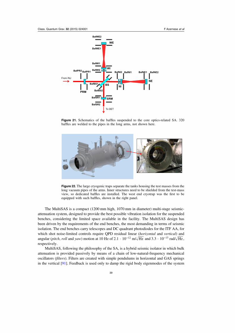
The MultiSAS is a compact (1200 mm high, 1070 mm in diameter) multi-stage seismic-attenuation system, designed to provide the best possible vibration isolation for the suspendedbenches, considering the limited space available in the facility. The MultiSAS design hasbeen driven by the requirements of the end benches, the most demanding in terms of seismicisolation. The end benches carry telescopes and DC quadrant photodiodes for the ITF AA, forwhich shot noise-limited controls require QPD residual linear (horizontal and vertical) andangular (pitch, roll and yaw) motion at 10 Hz of −2.1 · 10 12 m/ Hz and −3.3 · 10 15 rad/ Hz ,respectively.
MultiSAS, following the philosophy of the SA, is a hybrid seismic isolator in which bulkattenuation is provided passively by means of a chain of low-natural-frequency mechanicaloscillators (filters). Filters are created with simple pendulums in horizontal and GAS springsin the vertical [91]. Feedback is used only to damp the rigid body eigenmodes of the system
BafWE2
BafWI2BafPR1
BafBS1
BafBS2
BafSR1
BafSR2
BafPR2
BafWl1
BafWE1
BafNI2 BafNI1 BafNE1 BafNE2
WE
WI
From INJ
PRM
To DET
SRM
BS NI
NE
Figure 21. Schematics of the baffles suspended to the core optics-related SA. 320baffles are welded to the pipes in the long arms, not shown here.
Figure 22. The large cryogenic traps separate the tanks housing the test masses from thelong vacuum pipes of the arms. Inner structures need to be shielded from the test-massview, so dedicated baffles are installed. The west end cryotrap was the first to beequipped with such baffles, shown in the right panel.
Class. Quantum Grav. 32 (2015) 024001 F Acernese et al
39

and to maintain, in the long term, the position and orientation of the optical bench. High-frequency internal modes are handled, if needed, by means of passive resonant dampers. Themain components of the MultiSAS chain are illustrated in figure 26.
• A horizontal pre-isolation stage, built with a short (about 0.5 m) IP, tuned to a naturalfrequency of around 100 mHz, attenuates the bench motion in the microseismic peakband and allows its precise positioning at very low frequencies. The IP also provides aninertial platform on which to detect the recoil and actively damp the rigid body modes ofthe suspended chain. Passive attenuation between the IP itself and the optical bench isexploited to apply controls without re–injecting noise. The IP is equipped with LVDTposition sensors, geophones (L4–C from Sercel) and voice-coil actuators for dynamiccontrols. Stepper motor-driven correction springs are foreseen for static positioning withmicrometer accuracy.
• A vertical pre-isolation stage, called the top filter, consisting of a GAS spring, supportedby the IP platform and tuned to 200 mHz. The top filter is equipped with a stepper motor-driven static positioning spring, the so called fishing rod, and with a collocated LVDT/voice-coil pair for feedback control.
• A 100 kg mass intermediate stage, called the intermediate filter, consisting of a GASspring, tuned to 400 mHz and suspended from the pre-isolation stage via a 694 mm-longwire. The filter is equipped with a fishing rod and a LVDT/voice-coil actuator formonitoring and test purposes.
• The 320 kg mass optical bench, suspended from the intermediate filter, via a 760 mmlong wire. By adjusting the position of the bending point of the suspension wire withrespect to the bench center of mass, the tilt modes of the payload will be tuned around200 mHz, for better decoupling from the horizontal pendulum modes of the chain. The
Figure 23. Projection of the displacement noise of the cryotrap baffles. The overallnoise projection is estimated as the incoherent sum of the displacement noise comingfrom various baffle surfaces, multiplied by a factor of two to account for the fourcryotraps of the arm cavities (incoherent sum). The solid line is for high microseismicactivity (95th percentile upper limit), dashed line for usual microseismic activity (50thpercentile upper limit).
Class. Quantum Grav. 32 (2015) 024001 F Acernese et al
40

bench is equipped with two motorized counterweights for remote fine balancing and witha set of collocated LVDT coil-magnet actuators, referred to ground, for the local controlof the angular DoF.
More details of the MultiSAS control system are presented in [92]. The MultiSASseismic attenuation performance has been characterized by measuring its transfer function(see figure 27, left panel). The vertical isolation ratio exceeds 100 dB at all frequencies above10 Hz. In the horizontal, thanks to the three-stage design, a residual transmissibility around−180 dB has been measured. Transfer functions have been convoluted with the groundmotion spectra measured at the Virgo site to make estimates of the seismic motion of thebenches (figure 27, right panel).
14. Data acquisition
14.1. Real-time ITF synchronization and control
The ITF is a complex apparatus composed of a lot of subsystems, which have to worktogether in order to reach and keep the detector at the working point, with optimal sensitivityto GW. Of the order of one hundred active feedback systems are necessary to tune and controlthe whole detector. As an example, the positions of the suspended mirrors and benches haveto be controlled both individually, with local sensors when the ITF is not locked, and as a
Figure 24. Schematics of the baffle positions inside the Central Area. Baffles connectedto the vacuum links are depicted in blue, while the green baffles are suspended from thecore optics-related SA. In the top-left panel, a 3D-section view of the baffles foreseen inthe link WI-BS is shown, where clearance for the CO2 laser for the TCS is madepossible with a special baffle shape. The bottom-left panel shows a 3D rendering of thebaffle integrated into the BS payload. Also depicted: beams impinging on the BS mirrortravel clearly through the baffles.
Class. Quantum Grav. 32 (2015) 024001 F Acernese et al
41

Figure 25. Impression of the Minitower for the end benches.
Figure 26. Left panel: MultiSAS overview. Right panel: MultiSAS conceptual design;two vertical (GAS springs) and three horizontal (IP and two simple pendulums)isolation stages are provided.
Class. Quantum Grav. 32 (2015) 024001 F Acernese et al
42
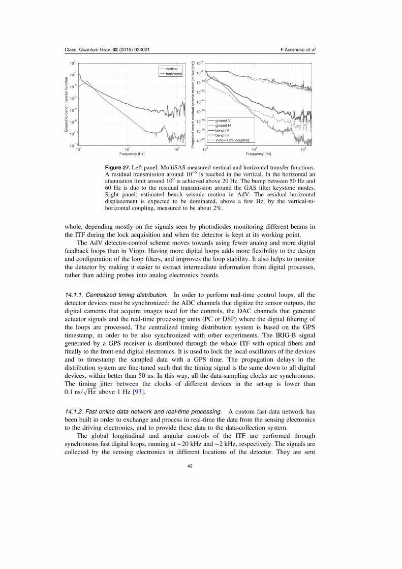
whole, depending mostly on the signals seen by photodiodes monitoring different beams inthe ITF during the lock acquisition and when the detector is kept at its working point.
The AdV detector-control scheme moves towards using fewer analog and more digitalfeedback loops than in Virgo. Having more digital loops adds more flexibility to the designand configuration of the loop filters, and improves the loop stability. It also helps to monitorthe detector by making it easier to extract intermediate information from digital processes,rather than adding probes into analog electronics boards.
14.1.1. Centralized timing distribution. In order to perform real-time control loops, all thedetector devices must be synchronized: the ADC channels that digitize the sensor outputs, thedigital cameras that acquire images used for the controls, the DAC channels that generateactuator signals and the real-time processing units (PC or DSP) where the digital filtering ofthe loops are processed. The centralized timing distribution system is based on the GPStimestamp, in order to be also synchronized with other experiments. The IRIG-B signalgenerated by a GPS receiver is distributed through the whole ITF with optical fibers andfinally to the front-end digital electronics. It is used to lock the local oscillators of the devicesand to timestamp the sampled data with a GPS time. The propagation delays in thedistribution system are fine-tuned such that the timing signal is the same down to all digitaldevices, within better than 50 ns. In this way, all the data-sampling clocks are synchronous.The timing jitter between the clocks of different devices in the set-up is lower than0.1 ns Hz above 1 Hz [93].
14.1.2. Fast online data network and real-time processing. A custom fast-data network hasbeen built in order to exchange and process in real-time the data from the sensing electronicsto the driving electronics, and to provide these data to the data-collection system.
The global longitudinal and angular controls of the ITF are performed throughsynchronous fast digital loops, running at ∼20 kHz and ∼2 kHz, respectively. The signals arecollected by the sensing electronics in different locations of the detector. They are sent
Figure 27. Left panel: MultiSAS measured vertical and horizontal transfer functions.A residual transmission around 10−6 is reached in the vertical. In the horizontal anattenuation limit around 109 is achieved above 20 Hz. The bump between 50 Hz and60 Hz is due to the residual transmission around the GAS filter keystone modes.Right panel: estimated bench seismic motion in AdV. The residual horizontaldisplacement is expected to be dominated, above a few Hz, by the vertical-to-horizontal coupling, measured to be about 2%.
Class. Quantum Grav. 32 (2015) 024001 F Acernese et al
43

through optical fibers to real-time processing units that run the digital servo-loops and sendthe data to other processing units or to the driving channels of the different ITF suspensions.A set of multiplexer/demultiplexer boards is used to route the data packets in the network.The data can be delivered from any ITF device to any other other ITF device with latenciesusually dominated by the optical fiber propagation time. New devices, called DAQ-boxes,will be installed in AdV: these are digital motherboards that can host specific mezzanines (forADC, DAC, digital demodulation channels, camera triggers, etc) and manage the interfacewith the timing and fast-data networks. The same interface is set in the electronics used tocontrol the suspensions. Some controls are performed locally: these are implemented bysending the data directly, on-board, from the sensing part to the driving part, where theneeded filtering is performed by the associated DSP.
Most of the sensor signals are digitized by ADC at ∼1 MHz and digitally low-passfiltered and decimated on-board, down to frequencies between a few kHz and a few tens ofkHz. The data are then sent to the fast-data network. Some are then used as error signals forfeedback loops and others are used to monitor the different subsystems and the detectorenvironment.
14.1.3. Digital demodulation. Demodulation will be used for many applications where errorsignals are needed. For example, LVDT will be used to locally control the positions of somesuspended benches. Instead of acquiring the error signal in the low-frequency band (below afew Hz), where the f1 noise of the ADC might not be negligible, the probe signal, which ismodulated at typically 10 kHz, is acquired at ∼40 kHz, and then demodulated in a real-timePC or in the on-board DSP in order to extract the error signal in a band in which the ADCnoise is lower than at low frequencies. Implementing such demodulation digitally addsflexibility to the choice and number of modulation frequencies, as well as the possibility tomodify them online to study, for example, cross-talk between LVDT.
The signals measured by the photodiodes are special cases. As explained in sections 10and 11, most of the photodiode signals are demodulated at frequencies between 6 MHz and132 MHz. In Virgo, the output signals of analog demodulation boards were digitized bystandard ADC. For AdV, digital demodulation will be used instead. The RF signals of thephotodiode are digitized in dedicated fast ADC at ∼500 MHz and the demodulationprocessing is computed on-board by a field programmable gate array (FPGA). The in-phaseand in-quadrature output channels are then low-pass filtered and decimated in the FPGA andin DSP, such that the frequencies of the final output channels, sent to the fast-data network,are ∼20 kHz. In this digital scheme, even in the case of demodulation at multiple frequencies,the RF output of a photodiode is acquired only once in a fast ADC and then different digitalcomputations are processed for the different frequencies. Compared to the analog solution,this reduces the number of cables and electronics boards. Another important advantage is thatit is not needed to distribute the local oscillator clocks from the laser modulator to all thedemodulation devices. The reference is the distributed timing signal used to lock the localclocks of the boards. The on-board timing distribution adds some low frequency phase noisethat can be subtracted online since it is common to all demodulation channels: the phase noisecan be monitored using either the demodulated photodiode signal at twice the mainfrequency, which also provides some sideband amplitude noise, or a 10 MHz clock, which isdistributed through the timing network.
14.1.4. Expected digital channels. The estimated numbers of front-end channels to beacquired or driven through the fast-data network of AdV are of the order of 2200 ADC with
Class. Quantum Grav. 32 (2015) 024001 F Acernese et al
44
sampling frequencies higher than 1 kHz, 1400 DAC, 100 digital demodulation inputs and 40cameras synchronized with the timing system.
14.2. Data collection
The goal of the data collection is to build different data streams and provide them both forlong-term storage on disk and online for commissioning, noise studies, data-quality defini-tions and h(t) reconstruction before data analysis. Data are generated all over the detector:they include ITF sensing and control signals, monitoring signals from all the detectorsubsystems and environmental-monitoring signals. They are acquired through the fast-datanetwork (∼400 MBytes s–1) and merged in different streams at the front-end of the datacollection pipeline. Data are then reduced (decimation, compression, image processing, etc) inorder to limit the flow on the Ethernet network and to require a reasonable storage amount ofdisk space. Data are then provided to several online processes (detector automation andmonitoring, data-quality tools, h(t) reconstruction) which enrich the streams with additionalcomputed channels that can be shared with other online processes. The data can be reached bya data-display tool to study the detector behavior online, with a latency of the order of asecond for the front-end data.
At the end of the data-collection tree, different data streams are stored on disk using theGW experiment data format [94]. The raw-data stream (2 TB/day) contains all of the channelsat their nominal sampling frequency, including the channels generated by the front-endelectronics and the channels generated by the online processes along the data-collection tree.Other streams are generated: a fast stream, with the channels stored at their maximum fre-quency, before any decimation of the data collection pipeline, in order to monitor and debugthe front-end electronics; a reduced data stream (RDS), 30 GB/day, with the channels deci-mated at lower frequencies than nominal (typically ∼100 Hz) for commissioning and noisestudies at low frequencies; trend-data streams, with statistical information computed over onesecond (4 GB/day) and a few tenths of seconds over all of the channels; the h(t) data stream(7 GB/day), which contains the reconstructed GW strain channel and data-quality flags, andthat can be directly used by the data analysis pipelines. The data are kept on circular buffers atthe Virgo site, with a depth of ∼6 months for the raw data. During science runs all the data aretransferred to computing centers for permanent storage and offline data analysis.
14.3. Calibration and h(t) reconstruction
The main output of the calibration and reconstruction procedures is the h(t) time series, whichdescribes the reconstructed GW strain signal. This is the main input for GW searches. ForAdV, the requirements from the different data-analysis groups, searching for compact binarycoalescences (CBC), bursts, continuous waves and stochastic sources, call for uncertaintiesbelow 10% in amplitude, 100 mrad in phase, μ25 s in timing. These are σ1 uncertaintiesgiven in the range 10 Hz to 2 kHz.
During Virgo [77], the systematic uncertainties of the reconstructed h(t) time seriesalready met these requirements. These were estimated to be 8% in amplitude, while h(t) was50 mrad in phase at 10 Hz, with a frequency dependence following a delay of μ8 s at highfrequency.
Consequently, the same calibration methods [95] will still be used for AdV. Similarly,the same method will be used for the h(t) reconstruction, in particular at the start of AdV, inthe power-recycled configuration. Developments will be needed to adapt the reconstructionwhen the SRM is added.
Class. Quantum Grav. 32 (2015) 024001 F Acernese et al
45
In parallel to the standard calibration methods, a photon calibrator has been used in Virgo[77] to validate, with independent measurements, the reconstructed h(t) time series. Animproved design of the photon calibrator is being defined for AdV. Two such devices will beinstalled, one on each end test mass.
15. Vacuum upgrades
The main vacuum enclosure is one single volume of about 7000 m3, consisting of severalparts [1, 7]:
• two 3 km long straight tubes, 1.2 m in diameter, hosting the ITF arms;• eleven vertical cylinders, called towers, containing the SA. These chambers have adiameter of 2 m. Three are 4.5 m high and host the short SA suspending the IMC mirrorand the injection/detection benches; seven are 11 m high and contain the long SAsuspending all of the other optics;
• one 142 m long tube, 30 cm in diameter, containing the mode cleaner optical cavity;• several valves, with up to 1 m aperture;• several pumping groups, including many types of pumps and vacuum gauges;• a few large cryostats.
To meet the sensitivity goal, a residual gas pressure of about 10−9mbar inside the 3 kmlong arm tubes is required, in order to suppress several sources of noise, the dominant sourcebeing the fluctuations of the refractive index due to the statistical fluctuations of the gasmolecule density on the 3 km path of the laser beams.
In order to cope with the vacuum and cleanliness prescriptions, a careful materialselection has been performed for all of the in-vacuum components, and suitable vacuum/thermal treatments have been developed and performed prior to installation.
1) Bake-out. Since it is mandatory to remove the layers of water molecules that stick tothe inner wall of the enclosure, a bake-out of the vacuum pipes may be performed at a laterstage to reach the final residual pressure. The chosen process consists of heating the pipes,once under vacuum, to °150 C for about one week. The baking equipment was installed andtested before the operation of Virgo. However, Virgo has been operated in unbaked condi-tions, since a pressure of 10−7 mbar was not limiting the sensitivity. The tubes will be bakedonly when necessary to improve the sensitivity of AdV and convenient for the schedule. Thetowers will not be baked to avoid the risk of damaging the suspended payloads. The migrationof water molecules from the unbaked towers to the 3 km pipes will be prevented by theinstallation of cryogenic traps (cryotraps) at each end of the pipes.
2) Firing. With the AdV operating pressure already in mind, all the constituents of theultra-high vacuum (UHV) enclosure (pipe modules and tower lower chambers) have beenfired in air at °400 C in order to reduce by at least a factor of 100 the outgassing of hydrogenfrom the stainless-steel walls. This makes it possible to meet the base pressure requirementswith only one pumping station every 600 m of pipe.
3) Cleanliness. The cleanliness of the optical surfaces is one of the most critical aspectsof operating the detector. For this reason, the residual gas must be free of condensable organicmolecules (hydrocarbons), and a conservative hydrocarbon partial pressure of 10−13mbar isrequired for the mirror vacuum chambers. The four large cryotraps at the ends of the 3 kmpipes will contribute to the fulfilment of the requirement by condensing hydrocarbon vapors.Each of the seven long towers is divided into two compartments: a lower vacuum chamber,
Class. Quantum Grav. 32 (2015) 024001 F Acernese et al
46
hosting the mirror; and an upper vacuum chamber, containing mechanical elements and theSA cables. The two volumes are separated by a mechanical structure (the so called separatingroof) with a low-conductance pipe in the center, for the passage of the suspension wireconnecting the payload to the upper stage. This low conductance (1.6 l s−1 or 0.4 l s−1 whendifferentially pumped) makes it possible to tolerate, in the tower upper part, a pressure up to10−6 mbar dominated by water. Similar conditions are also obtained in the three short towers,which are separated from the mirror towers by two additional cryotraps. The common goal forall the evacuated volumes is to keep them free of dust, avoiding optics contamination duringany maintenance operations.
15.1. Pumping system
Most of the Virgo pumps are still used in AdV. The upper and lower chambers of each towerare separately pumped by a turbo-molecular group, consisting of a 1500 l s-1 turbo, backed bya dry scroll pump, also used for roughing. Turbo pumps of the hybrid type with magneticsuspensions are used to reduce noise and maintenance. To further reduce vibrations, the scrollpumps have been moved to a distant and acoustically isolated room, while the turbo pumpsare anchored to ground and connected to the towers with soft bellows. Over the next fewyears, and only if really needed, the turbo pumps will be progressively replaced by quieter ionpumps (which have lower seismic, acoustic and magnetic emissions).
In the arm tubes, roughing and intermediate phases are achieved with a large drymechanical pumping group. Evacuation continues with a turbo-molecular group similar tothose of the towers every 600 m. Final vacuum will be reached after baking and maintainedby titanium sublimation pumps, which are most suited to pump hydrogen (3000 l s-1) andsmaller ion pumps (70 l s-1) to handle inert gases. Periodical regeneration of a Ti evaporatedlayer will slightly lower the pumping duty cycle; normally five out of seven groups will be inoperation along each arm.
A layout of the pumping system is shown in figure 28.
15.2. Cryogenics
The water migrating from the towers to the 3 km pipes will be stopped by four large cryo-traps, one at each end of the arm pipes, and by two smaller ones, between the bench towersand the recycling towers. The large cryotraps are installed between the input/end towers andthe corresponding large valve. They consist (figure 29) of a vacuum pipe, which is about 3 mlong and 1.4 m in diameter, containing a 2 m long tank with the shape of a sleeve and filledwith about 300 l of liquid nitrogen at 77 K. The sleeve has been built in aluminum for a moreuniform temperature distribution; with an inner diameter of 0.95 m, it has a 6 m2 cold surfaceto capture water and other condensable gases. The outer wall of the cold tank is centered awayfrom the beam axis maximizing the liquid/gaseous nitrogen open surface, to allow a smoothevaporation and reducing the bubbling noise. The cold tank is thermally shielded by a two-fold aluminum foil screen, while the free aperture for the laser beam is limited to a 600 mmdiameter by suitable thermal and optical baffles.
The escaping fraction of water molecules is estimated to be about 3%; the thermal loss,verified on the first built trap, is 250W, corresponding to a consumption of 5.6 l h-1 of liquidnitrogen and 1 l s-1 of gas at 80 K. Consumption depends also on the thickness of the icedeposit, which grows progressively by about 1 micron per year (figure 29) and causes a slowincrease of infrared emissivity. Regenerations are not envisaged to take place more than onceper year; the process will take about one week or slightly more.
Class. Quantum Grav. 32 (2015) 024001 F Acernese et al
47
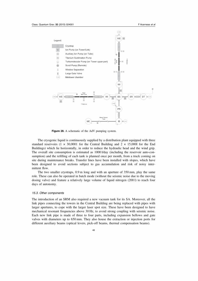
The cryogenic liquid is continuously supplied by a distribution plant equipped with threestandard reservoirs (1 × 30,0001 for the Central Building and 2 × 15,000l for the EndBuildings) which lie horizontally, in order to reduce the hydraulic head and the wind grip.The overall site consumption is estimated as 1000 l/day (including the reservoir auto-con-sumption) and the refilling of each tank is planned once per month, from a truck coming onsite during maintenance breaks. Transfer lines have been installed with slopes, which havebeen designed to avoid sections subject to gas accumulation and risk of noisy inter-mittent flow.
The two smaller cryotraps, 0.9 m long and with an aperture of 350 mm, play the samerole. These can also be operated in batch mode (without the seismic noise due to the movingdosing valve) and feature a relatively large volume of liquid nitrogen (200 l) to reach fourdays of autonomy.
15.3. Other components
The introduction of an SRM also required a new vacuum tank for its SA. Moreover, all thelink pipes connecting the towers in the Central Building are being replaced with pipes withlarger apertures, to cope with the larger laser spot size. These have been designed to havemechanical resonant frequencies above 30 Hz, to avoid strong coupling with seismic noise.Each new link pipe is made of three to four parts, including expansion bellows and gatevalves with diameters up to 650 mm. They also house the extraction or injection ports fordifferent auxiliary beams (optical levers, pick-off beams, thermal compensation beams).
Figure 28. A schematic of the AdV pumping system.
Class. Quantum Grav. 32 (2015) 024001 F Acernese et al
48

The new vacuum system is completed by a complex control system, based on thirty-threemain stations. Each station makes it possible to operate the equipment (pumps, gauges,valves) in local or remote mode, assuring inter-locks and loops that actively protect thesystem against incorrect actions or failures.
16. In conclusion
In this paper we have reviewed the main aspects of the AdV project, in the context of theforthcoming network of second-generation interferometric GW detectors. Despite the absenceof a detection, the first-generation detectors were a great success: they established theinfrastructure which will also be used for the second generation; the interferometric detectortechnology has been demonstrated, since the design sensitivities has been reached (and evensurpassed) and very good robustness has been achieved; a world-wide network of GWdetectors has been built and the first steps towards a multi-messenger approach have beentaken; concrete methods for the analysis of the data have been established; and many papersproviding results that have had an impact on our understanding of the universe have beenpublished. The technology in our hands and the experience achieved with the first-generationdetectors make it possible to increase by a factor of one thousand the volume of the universewe can survey with the advanced detectors and, consequently, the detection probability. Thismakes the forthcoming years very exciting.
References
[1] The Virgo Collaboration 2012 JINST 7 3012[2] Gonzalez G, Viceré A and Wen L 2013 Front. Phys. 8 771[3] Cerdonio M and Losurdo G 2012 Riv. Nuovo Cimento 35 389[4] Pitkin M, Reid S, Rowan S and Hough J 2011 Living Rev. Relativ. 14 5[5] The LIGO Scientific Collaboration this issue[6] The GEO600 Collaboration this issue[7] The Virgo Collaboration 2012 Advanced Virgo technical design report Virgo Internal Document
VIR-0128A-12 https://tds.ego-gw.it/itf/tds/file.php?callFile=VIR-0128A-12.pdf[8] Finn L S and Chernoff D F 1993 Phys. Rev. D 47 2198[9] http://ilog.ligo-wa.caltech.edu:7285/advligo/GWINC
0 0.5 1 1.5 2distance from the inlet [m]
2.E-06
1.E-06
0.E+00
tichk
ness
[m]
Figure 29. A view of the arm cryotrap: the inner cryogenic vessel is in light gray. Onthe left: evaluation of the ice layer build up inside a trap after one year of service in‘run’ or ‘commissioning’ mode.
Class. Quantum Grav. 32 (2015) 024001 F Acernese et al
49
[10] Pinard L, Flaminio R and Forest D 2010 Bulk absorption measurement at 1064 nm of the newHeraeus ultra pure fused silica used for the Advanced Virgo Test Mass: effect of the annealingVirgo Note VIR-0091A-10 (https://tds.ego-gw.it/ql/?c=7215)
[11] Numata K, Yamamoto K, Ishimoto H, Otsuka S, Kawabe K, Ando M and Tsubono K 2004Systematic measurement of the intrinsic losses in various kinds of bulk fused silica Phys. Lett.A 327 263–71
[12] Brillet A et al 2003 Phys. Rev. D 67 102006[13] Comtet C et al 2007 Proc. of the 42nd Rencontres de Moriond ed J Dumarchez and J T T Van
(Vietnam: Gioi)[14] Cimma B et al 2006 Appl. Opt. 45 1436–9[15] Acernese F et al 2008 J. Phys.: Conf. Ser. 120 032007[16] Abbott B P et al 2009 Rep. Prog. Phys. 72 076901[17] Accadia T et al 2011 Proc. of the 12th Marcell Grossmann Meeting ed T Damour, R T Jantzen and
R Ruffini (Singapore: World Scientific)[18] Hello P 2001 Eur. Phys. J. D 15 373–83[19] Vinet J Y 2009 Living Rev. Relativ. 12 5[20] Rocchi A et al 2011 Proc. of the 46th Rencontres de Moriond ed E Auge, J Dumarchez and
J T T Van (Vietnam: Gioi)[21] Rocchi A et al 2012 J. Phys.: Conf. Ser. 363 012016[22] Rocchi A 2014 Advanced Interferometers and The Searches for Gravitational Waves
(Astrophysics and Space Science Library vol 404) ed M Bassan (Berlin: Springer)[23] Lawrence R C 2003 PhD Thesis MITLIGO-P030001–00-R MIT, Cambridge, Massachusetts[24] Goda K, Ottaway D, Connelly B, Adhikari R, Mavalvala N and Gretarsson A 2004 Opt. Lett.
29 1452[25] Day R 2011 Simulation of use of phase camera as sensor for correcting common high order
aberrations in MSRC VIR-0389A-11 Virgo Note[26] Fan Y et al 2008 Rev. Sci. Instrum. 79 104501[27] Brooks A F et al 2007 Opt. Express 15 10370–5[28] Conte A, Puppo P and Rapagnani P 2013 Thermal noise evaluation of the compensation plate
Virgo Technical Note VIR-0469A-13 (https://tds.ego-gw.it/ql/?c=9851)[29] Levin Y 1998 Phys. Rev. D 57 659[30] Cagnoli G G et al 1999 Phys. Lett. A 255 230[31] Huang Y L and Saulson P R P R 1997 Rev. Sci. Instrum. 69 544[32] Gretarsson A M and Harry G M 1999 Rev. Sci. Instrum. 70 4081[33] Cagnoli G et al 2000 Phys. Rev. Lett. 85 2442[34] Grote H 2008 Class. Quantum Grav. 25 114043[35] Braginsky V B et al 1994 Phys. Lett. A 186 18[36] Accadia T et al 2011 Class. Quantum Grav. 28 114002[37] Puppo P, Colombini M, Nardecchia I, Majorana E, Rapagnani P and Ricci F 2012 Virgo+ thermal
noise study Virgo Technical Note VIR-0074B-12 (https://tds.ego-gw.it/ql/?c=8878)[38] Cagnoli G et al 2000 Phys. Lett. A 272 39[39] Liu Y T and Thorne K S 2000 Phys. Rev. D 62 122002[40] Piergiovanni F et al 2010 J. Phys.: Conf. Ser. 228 012017[41] Acernese F et al 2010 Astropart. Phys. 33 182–9[42] Losurdo G et al 1999 Rev. Sci. Instrum. 70 2507[43] Braccini S et al 1995 Rev. Sci. Instrum. 66 2672[44] Losurdo G et al 2001 Rev. Sci. Instrum. 72 3653[45] Accadia T et al 2011 Rev. Sci. Instrum. 82 094502[46] Giazotto A 2012 Phys. Lett. A 376 667–70[47] Venkateswara K et al 2014 Rev. Sci. Instrum. 85 015005[48] Rozelle D M 2014 The hemispherical resonator gyro: from wineglass to the planets Northrop
Grumman White Paper[49] Nebylov A 2013 Aerospace Sensors (New York: Momentum)[50] Bryan G H 1890 On the beats in the vibrations of a revolving cylinder or bell Cambridge Phil. Soc.
7 101[51] Whittaker E A, Gehrtz M and Bjorklund G C 1985 J. Opt. Soc. Am. B 2 1320–6
Class. Quantum Grav. 32 (2015) 024001 F Acernese et al
50
[52] Barone F, Calloni E, di Fiore L, Grado A, Hello P, Milano L and Russo G 1996 Effects ofmisalignments and beam jitters in interferometric gravitational wave detectors Phys. Lett. A 21790–96
[53] Fritschel P, Mavalvala N, Shoemaker D, Sigg D, Zucker M and González G 1998 Appl. Opt. 376734–47
[54] Canuel B, Genin E, Mantovani M, Marque J, Ruggi P and Tacca M 2014 Appl. Opt. 53 2906–16[55] Stochino A et al 2009 Nucl. Instrum. Methods Phys. Res. A 598 737–53[56] Wanner A, Bergmann G, Bertolini A, Fricke T, Lück H, Mow-Lowry C M, Strain K A,
Gossler S and Danzmann K 2012 Class. Quantum Grav. 29 245007[57] Blom M R, Beker M G, Bertolini A, van den Brand J F J, Bulten H J, Hennes E, Mul F A,
Rabeling D S and Schimmel A 2013 Nucl. Instrum. Methods Phys. Res. A 718 466–70[58] Bertolini A, Cella G, DeSalvo R and Sannibale V 1999 Nucl. Instrum. Methods Phys. Res. A 435
475–83[59] The Virgo Collaboration 2004 Class. Quantum Grav. 21 S395–402[60] Khazanov E et al 1999 IEEE J. Quantum Electron. 35 1116–22[61] Mosca S, Canuel B, Karimi E, Piccirillo B, Marrucci L, de Rosa R, Genin E, Milano L and
Santamato E 2010 Phys. Rev. A 82 043806[62] The Virgo Collaboration 2008 Appl. Opt. 47 5853–61[63] Palashov O V et al 2012 J. Opt. Soc. Am. B 29 1784–92[64] Khazanov E A 1999 Quantum Electron. 29 59–64[65] The Virgo Collaboration 2010 Appl. Opt. 49 4780–90[66] Zelenogorsky V, Palashov O and Khazanov E 2007 Opt. Commun. 278 8–13[67] Barsuglia M, Buy C, Canuel B, Day R, Genin E and Vajente G 2012 AdV INJ: mode matching
telescope configuration choice for the ITF input telescope VIR-0010A-12 Virgo Note (https://tds.ego-gw.it/ql/?c=8812)
[68] Amarni J, Baronick J-P, Barsuglia M, Bertoli W, Buy C, Gatto A and Tacca M 2013 AdvancedVirgo injection mode-matching telescope mechanics VIR-0584A-13 Virgo Note (https://tds.ego-gw.it/ql/?c=9977)
[69] Allemandou N et al 2014 Minitowers benches mechanical design and tests with a dummy benchVirgo Note VIR-0229A-14 (https://tds.ego-gw.it/ql/?c=10256)
[70] Casula P A, Digallo L, Gouaty R, Marion F, Mours B and Rolland L 2012 Advanced Virgo outputmode cleaner: refinement of the design and polishing specifications Virgo Note VIR-0319A-12(https://tds.ego-gw.it/ql/?c=9140)
[71] Gouaty R, Bonnand R, Marion F, Mours B and Rolland L Advanced Virgo output mode cleaner:optimization of the cavity parameters to minimize the thermo-refractive noise Virgo Note VIR-0016A-13 (https://tds.ego-gw.it/ql/?c=9359)
[72] Bouedo T, Dalmaz A, Gouaty R, Hermel R, Letendre N, Masserot A, Mours B, Pacaud E,Petit S and Rolland L 2012 Tests of the digital demodulation prototype board for the AdVphotodiode readout Virgo Note VIR-0476A-12 (https://tds.ego-gw.it/ql/?c=9299)
[73] Fricke T T et al 2012 DC readout experiment in enhanced LIGO Class. Quantum Grav. 29 065005[74] Evans M Optickle frequency domain Matlab methods for doing interferometer simulation (https://
awiki.ligo-wa.caltech.edu/aLIGO/ISC_Modeling_Software)[75] Vajente G 2011 Advanced Virgo length sensing and control steady state design Virgo Note VIR-
0738A-1 (https://tds.ego-gw.it/ql/?c=8797)[76] Swinkels B, Campagna E, Vajente G, Barsotti L and Evans M 2008 Longitudinal noise subtraction
Virgo Note VIR-0050A-08 (https://tds.ego-gw.it/ql/?c=2055)[77] Accadia T et al 2014 Class. Quantum Grav. 31 165013[78] Yamamoto H et al End to end time-domain optical simulator (http://www.ligo.caltech.edu/~e2e/)[79] Acernese F et al 2006 Class. Quantum Grav. 23 S85[80] Ward R 2010 Length sensing and control of a prototype advanced interferometric gravitational
wave detector PhD Thesis California Institute of Technology Pasadena, CA[81] Izumi K et al 2012 J. Opt. Soc. Am. A 29 2092–103[82] Mantovani M 2011 Automatic alignment sensing and control scheme for Advanced Virgo MSRC
configuration Virgo Internal Document VIR-0201A-11 (https://tds.ego-gw.it/itf/tds/file.php?callFile=VIR-0201A-11.pdf)
[83] The Virgo Collaboration 2010 Astropart. Phys. 33 131–9[84] The Virgo Collaboration 2011 Astropart. Phys. 34 327–32
Class. Quantum Grav. 32 (2015) 024001 F Acernese et al
51
[85] Freise A, Heinzel G, Luck H, Schilling R, Willke B and Danzmann K 2004 Class. Quantum Grav.21 S1067
[86] Chiummo A, Day R and Marque J 2013 AdV-stray light control: requirements for wide-anglescattering in the arm cavity Virgo Internal Note VIR-0055A-13 (https://tds.ego-gw.it/ql/?c=9398)
[87] Day R 2012 A new FFT code: FOG fast Fourier transform optical simulation of gravitational waveinterferometers (https://dcc.ligo.org/LIGO-G1200629/public)
[88] Chiummo A, Moggi A and Marque J 2013 AdV—SLC: baffling design around the cryogenic trapsVirgo Internal Note Gravitational Wave Advanced Detector Workshop (14 May 2012,Waikoloa Marriott Resort, HI) VIR-0417B-13 (https://tds.ego-gw.it/ql/?c=9771)
[89] Chiummo A, Canuel B, Magazzu A and Marque J 2012 AdV SLC: characterization of siliconcarbide for constructing baffles and beam dumps in AdV Virgo Internal Note VIR-0460A-12(https://tds.ego-gw.it/ql/?c=9283)
[90] Chiummo A, Canuel B, Magazzu A and Marque J 2013 AdV SLC: characterization of diamond-like carbon for constructing baffles and beam dumps in AdV Virgo Internal Note VIR-0127A-13 (https://tds.ego-gw.it/ql/?c=9472)
[91] Marka S et al 2002 Class. Quantum Grav. 19 1605[92] Beker M G, Bertolini A, van den Brand J F J, Bulten H J, Hennes E and Rabeling D 2014 Rev. Sci.
Instrum. 85 034501[93] Rolland L et al 2010 Stability of the timing system during VSR2 Virgo Note VIR-0354A-10
(https://tds.ego-gw.it/ql/?c=7509)[94] Blackburn K, Lazzarini A and Mours B 1997 Specification of a common data frame format for
interferometric gravitational wave detectors LIGO-Virgo Note LIGO-T970130-v1 (https://dcc.ligo.org/LIGO-T970130/public)
[95] Accadia T et al 2011 Class. Quantum Grav. 28 025005
Class. Quantum Grav. 32 (2015) 024001 F Acernese et al
52