advanced distribution automation with der function · functional requirements for advanced...
TRANSCRIPT
IECSA Volume II D29-i Final Release ADA Use Cases.doc
FFuunnccttiioonnaall RReeqquuiirreemmeennttss ffoorr AAddvvaanncceedd DDiissttrriibbuuttiioonn AAuuttoommaattiioonn wwiitthh DDEERR ((AADDAA--DDEERR))
1 Descriptions of Function..................................................................................................................................................................... 1
1.1 Function Name............................................................................................................................................................................ 1
1.2 Function ID ............................................................................................................................................................................... 1
1.3 Brief Description ...................................................................................................................................................................... 1
1.4 Narrative .................................................................................................................................................................................... 2
1.4.1 Overview of ADA Functions .............................................................................................................................................. 2
1.4.1.1 Overview Diagrams ........................................................................................................................................................ 2
1.4.1.2 Overall Preconditions...................................................................................................................................................... 5
1.4.1.3 Overview of Post Conditions .......................................................................................................................................... 6
1.4.2 Distribution Operation Modeling and Analysis (DOMA).................................................................................................. 7
1.4.2.1 Modeling Transmission/Sub-Transmission System Immediately Adjacent to Distribution Circuits............................. 8
1.4.2.2 Modeling Distribution Circuit Connectivity................................................................................................................... 8
1.4.2.3 Modeling Distribution Nodal Loads ............................................................................................................................... 9
1.4.2.4 Modeling Distribution Circuit Facilities......................................................................................................................... 9
1.4.2.5 Distribution Power Flow................................................................................................................................................. 9
1.4.2.6 Evaluation of Transfer Capacity ..................................................................................................................................... 9
1.4.2.7 Power Quality Analysis ................................................................................................................................................ 10
1.4.2.8 Loss Analysis ................................................................................................................................................................ 10
1.4.2.9 Fault Analysis ............................................................................................................................................................... 10
1.4.2.10 Evaluation of Operating Conditions ......................................................................................................................... 10
1.4.3 Fault Location, Isolation and Service Restoration (FLIR)................................................................................................ 11
IECSA Volume II D29-ii Final Release ADA Use Cases.doc
1.4.3.1 Fault Location ............................................................................................................................................................... 11
1.4.3.2 Fault Isolation and Service Restoration ........................................................................................................................ 11
1.4.4 Contingency Analysis (CA).............................................................................................................................................. 11
1.4.5 Multi-level Feeder Reconfiguration (MFR)...................................................................................................................... 12
1.4.6 Relay Protection Re-coordination (RPR).......................................................................................................................... 12
1.4.7 Voltage and Var Control (VVC)....................................................................................................................................... 13
1.4.8 Pre-arming of Remedial Action Schemes (RAS) ............................................................................................................. 13
1.4.9 Coordination of Emergency Actions ................................................................................................................................ 14
1.4.10 Coordination of Restorative Actions ................................................................................................................................ 14
1.4.11 Intelligent Alarm Processing............................................................................................................................................. 14
1.5 Actor (Stakeholder) Roles ..................................................................................................................................................... 14
1.6 Information exchanged .......................................................................................................................................................... 19
1.7 Activities/Services.................................................................................................................................................................. 23
1.8 Contracts/Regulations ............................................................................................................................................................ 25
2 Step by Step Analysis of Function.................................................................................................................................................... 28
2.1 Distribution Operation Modeling and Analysis (DOMA) Function......................................................................................... 28
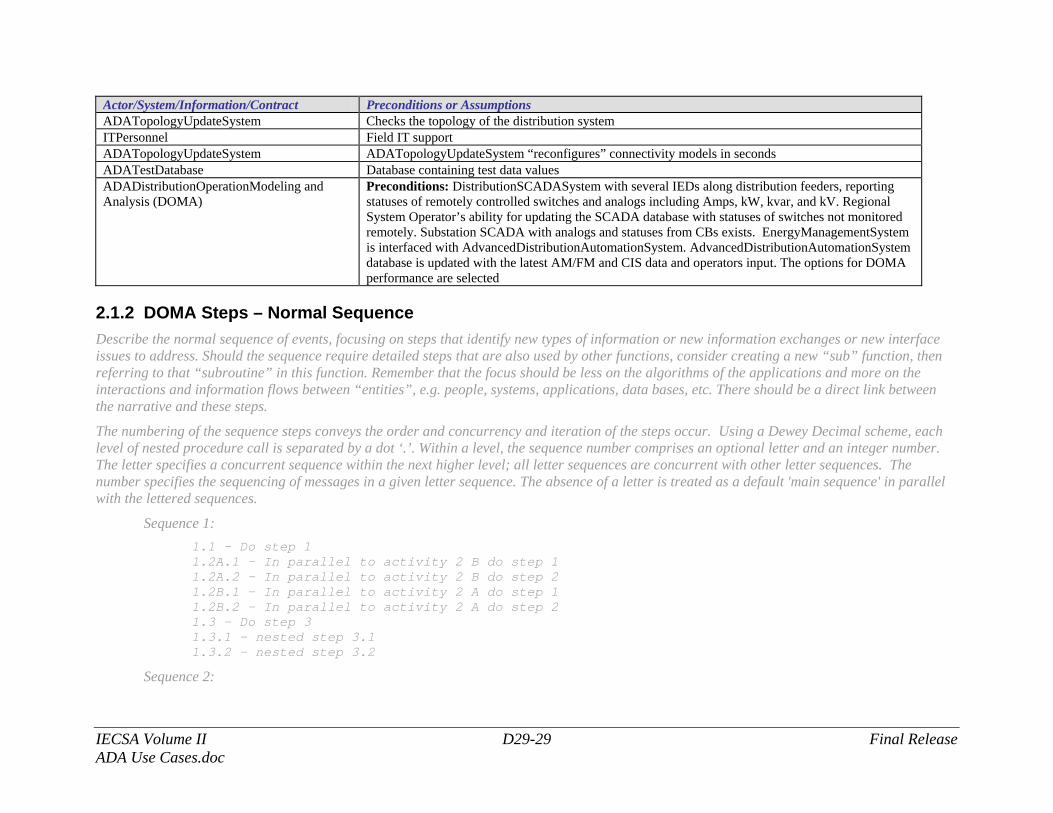
2.1.1 DOMA Preconditions and Assumptions........................................................................................................................... 28
2.1.2 DOMA Steps – Normal Sequence .................................................................................................................................... 29
2.1.2.1 Data Conversion and Validation....................................................................................................................................... 30
2.1.2.2 DOMA No Events............................................................................................................................................................. 39
2.1.2.3 DOMA Event Run ............................................................................................................................................................ 41
2.1.2.4 DOMA Scheduled Run..................................................................................................................................................... 48
2.1.2.5 DOMA Study/Look-ahead Mode ..................................................................................................................................... 52
IECSA Volume II D29-iii Final Release ADA Use Cases.doc
2.1.3 Steps – Alternative / Exception Sequences.............................................................................................................................. 57
2.1.4 Post-conditions and Significant Results................................................................................................................................... 58
2.1.5 Diagrams .................................................................................................................................................................................. 58
2.2 Fault Location, Isolation and Service Restoration (FLIR) Function .............................................................................................. 64
2.2.1 FLIR Preconditions and Assumptions ..................................................................................................................................... 64
2.2.2 FLIR Steps – Normal Sequence............................................................................................................................................... 65
2.2.2.1 FLIR First Fault with Only Manual Switches................................................................................................................... 66
2.2.2.2 FLIR Second Fault (Related to First Fault which is Not Resolved Yet) with Only Manual Switches ............................ 72
2.2.2.3 FLIR Fault with Remotely-Controlled and Manual Switches .......................................................................................... 87
2.2.2.4 FLIR Fault with Remotely-Controlled and Manual Switches and Distributed Intelligence System (DIS)...................... 97
2.2.2.5 FLIR Fault with DER Connected to Healthy Section..................................................................................................... 108
2.3.1 Post-conditions and Significant Results.......................................................................................................................... 113
2.3.2 Diagrams ......................................................................................................................................................................... 113
2.3 Volt/Var Control function (VVC)........................................................................................................................................... 119
2.3.1 VVC Preconditions and Assumptions ............................................................................................................................ 119
2.3.2 VVC Steps – Normal Sequence...................................................................................................................................... 120
2.3.2.1 VVC Function During Scheduled Run ........................................................................................................................... 121
2.3.2.2 VVC Function During Event Run................................................................................................................................... 124
2.3.2.3 VVC Function Participation in Severe Emergency in Bulk Power System with Intentional Islands............................. 133
2.3.3 Post-conditions and Significant Results.......................................................................................................................... 136
2.3.4 Diagrams ......................................................................................................................................................................... 137
2.4 Architectural Issues in Interactions .................................................................................................................................... 140
2.5 Current Implementation Status ........................................................................................................................................... 141
IECSA Volume II D29-iv Final Release ADA Use Cases.doc
3 Auxiliary Issues........................................................................................................................................................................ 142
3.1 References and Contacts ......................................................................................................................................................... 142
3.1.1 Prior Published Work of UCI and UCI’s Personnel ...................................................................................................... 142
3.2 Action Item List .................................................................................................................................................................... 145
3.3 Revision History ................................................................................................................................................................... 147
IECSA Volume II D29-1 Final Release ADA Use Cases.doc
FFuunnccttiioonnaall RReeqquuiirreemmeennttss ffoorr AAddvvaanncceedd DDiissttrriibbuuttiioonn AAuuttoommaattiioonn wwiitthh DDEERR ((AADDAA--DDEERR)) AAddvvaanncceedd DDiissttrriibbuuttiioonn AAuuttoommaattiioonn wwiitthh DDEERR ((AADDAA--DDEERR)) FFuunnccttiioonn
UUssee CCaassee DDeessccrriippttiioonn11
1 Descriptions of Function All prior work (intellectual property of the company or individual) or proprietary (non-publicly available) work should be so noted.
1.1 Function Name Name of Function The function (further referred as Function) is named Advanced Distribution Automation (ADA) Function.
1.2 Function ID IECSA identification number of the function L-3,L-3.1,L-3.2,L-3.3,L-3.4,L-3.5,L-3.6,L-3.8,L-3.9
1.3 Brief Description Describe briefly the scope, objectives, and rationale of the Function.
Objective: The objective of Advanced Distribution Automation Function is to enhance the reliability of power system service, power quality, and power system efficiency, by automating the following three processes of distribution operation control: data preparation in near-real-time; optimal decision-making; and the control of distribution operations in coordination with transmission and generation systems operations. Scope: The AdvancedDistributionAutomationSystem Function performs a) data gathering, along with data consistency checking and correcting; b) integrity checking of the distribution power system model; c) periodic and event-driven system modeling and analysis; d) current and predictive alarming; e) contingency analysis; f) coordinated volt/var optimization: g) fault location, isolation, and service restoration; h) multi-level feeder reconfiguration; i) pre-arming of RAS and coordination of emergency actions in distribution; j) pre-arming of restoration schemes and coordination of restorative actions in distribution, and k) logging and reporting. These processes are performed through direct interfaces with different databases and systems, (EMS, OMS, CIS, MOS, SCADA,
1 Background information includes prior UCI work
IECSA Volume II D29-2 Final Release ADA Use Cases.doc
AM/FM/GIS, AMS and WMS), comprehensive near real-time simulations of operating conditions, near real-time predictive optimization, and actual real-time control of distribution operations. Rationale: By meeting its objectives in near-real time, the Function makes a significant contribution to improving the power system operations through automation, which cannot be achieved using existing operational methods. Status: The methodology and specification of the Function for current power system conditions have been developed, and prototype (pilot) and system-wide project in several North-American utilities have been implemented by Utility Consulting International and its client utilities prior to the IECSA project.
1.4 Narrative A complete narrative of the Function from a Domain Expert’s point of view, describing what occurs when, why, how, and under what conditions. This will be a separate document, but will act as the basis for identifying the Steps in Section 2.
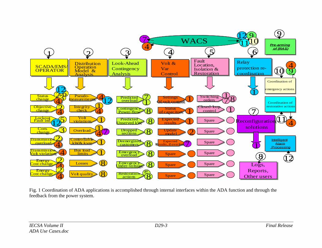
1.4.1 Overview of ADA Functions The AdvancedDistributionAutomationSystem Function operates via the following closely coordinated applications:
1.4.1.1 Overview Diagrams
IECSA Volume II D29-3 Final Release ADA Use Cases.doc
DistributionOperationModel &Analysis
Look-AheadContingencyAnalysis
Volt &VarControl
FaultLocation,Isolation & Restoration
2 3 4 5
SCADA/EMS/OPERATOR
1
StatuschangeStatuschange 22
Objectivechange
Objectivechange
LockoutFault ind.Lockout
Fault ind.
Com.changeCom.change
Transmissionoverload
Transmissionoverload
TransmissionVolt violationTransmissionVolt violation
EnergyCost change
EnergyCost change
Pseudo-measurements
Pseudo-measurements 4
Integritycheck
Integritycheck
1Volt
violationsVolt
violations 1OverloadOverload 1
ControllablekW& kvar
ControllablekW& kvar 1
Bus loadlimits
Bus loadlimits 1LossesLosses 8
Volt qualityVolt quality 8
Predictedoverload
Predictedoverload 7
ContingencyPower-flow
ContingencyPower-flow 8
PredictedUnserved kW
PredictedUnserved kW 8
Droppedsections
Droppedsections 8
Deenergizedcustomers
Deenergizedcustomers 8Emergencyoverload
Emergencyoverload 8
EmergencyUnder-voltageEmergency
Under-voltage 8Restoration
actionsRestoration
actions 5
SettingsOf volt control
SettingsOf volt control 1
Statusof capacitors
Statusof capacitors 1
Expectedresults
Expectedresults 1Updatemodel
Updatemodel 2
ExpectedResults, if overload
ExpectedResults, if overload
SpareSpare
SpareSpare
SpareSpare
Switchingorders
Switchingorders
1Closed- loop
controlClosed- loop
control 1SpareSpare
SpareSpare
SpareSpare
SpareSpare
SpareSpare
SpareSpare
3442453
2244424
Relay protection re-coordination
6
6
EnergyCost change
EnergyCost change
24
1
Reconfigurationsolutions
Reconfigurationsolutions
Logs,Reports,
Other users
Logs,Reports,
Other users
7
18
4
4
1
8
7 8
77
Coordination of
emergency actions
Coordination of
emergency actions
Pre-armingof (RAS)
Pre-armingof (RAS)
Coordination ofrestorative actionsCoordination of
restorative actions
Intelligent Alarm
Processing
Intelligent Alarm
Processing
9
10
11
12
WACS91011
1274
9
4
12
12
12
4DistributionOperationModel &Analysis
Look-AheadContingencyAnalysis
Volt &VarControl
FaultLocation,Isolation & Restoration
2 3 4 5
SCADA/EMS/OPERATOR
1
StatuschangeStatuschange 22
Objectivechange
Objectivechange
LockoutFault ind.Lockout
Fault ind.
Com.changeCom.change
Transmissionoverload
Transmissionoverload
TransmissionVolt violationTransmissionVolt violation
EnergyCost change
EnergyCost change
Pseudo-measurements
Pseudo-measurements 4
Integritycheck
Integritycheck
1Volt
violationsVolt
violations 1OverloadOverload 1
ControllablekW& kvar
ControllablekW& kvar 1
Bus loadlimits
Bus loadlimits 1LossesLosses 8
Volt qualityVolt quality 8
Predictedoverload
Predictedoverload 7
ContingencyPower-flow
ContingencyPower-flow 8
PredictedUnserved kW
PredictedUnserved kW 8
Droppedsections
Droppedsections 8
Deenergizedcustomers
Deenergizedcustomers 8Emergencyoverload
Emergencyoverload 8
EmergencyUnder-voltageEmergency
Under-voltage 8Restoration
actionsRestoration
actions 5
SettingsOf volt control
SettingsOf volt control 1
Statusof capacitors
Statusof capacitors 1
Expectedresults
Expectedresults 1Updatemodel
Updatemodel 2
ExpectedResults, if overload
ExpectedResults, if overload
SpareSpare
SpareSpare
SpareSpare
Switchingorders
Switchingorders
1Closed- loop
controlClosed- loop
control 1SpareSpare
SpareSpare
SpareSpare
SpareSpare
SpareSpare
SpareSpare
3442453
2244424
Relay protection re-coordination
6
6
EnergyCost change
EnergyCost change
24
1
Reconfigurationsolutions
Reconfigurationsolutions
Logs,Reports,
Other users
Logs,Reports,
Other users
7
18
4
4
1
8
7 8
77
Coordination of
emergency actions
Coordination of
emergency actions
Pre-armingof (RAS)
Pre-armingof (RAS)
Coordination ofrestorative actionsCoordination of
restorative actions
Intelligent Alarm
Processing
Intelligent Alarm
Processing
9
10
11
12
WACS91011
1274
9
4
12
12
12
4
Fig. 1 Coordination of ADA applications is accomplished through internal interfaces within the ADA function and through the feedback from the power system.
IECSA Volume II D29-4 Final Release ADA Use Cases.doc
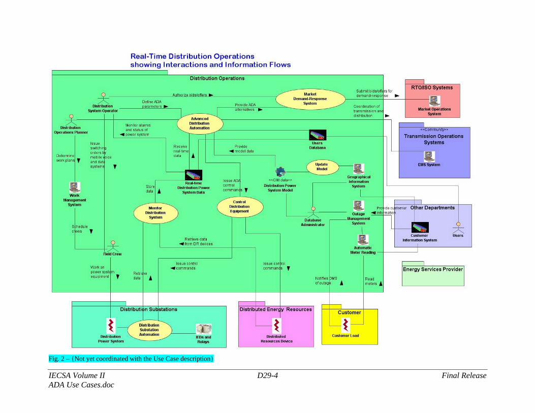
Fig. 2 – {Not yet coordinated with the Use Case description}
IECSA Volume II D29-5 Final Release ADA Use Cases.doc
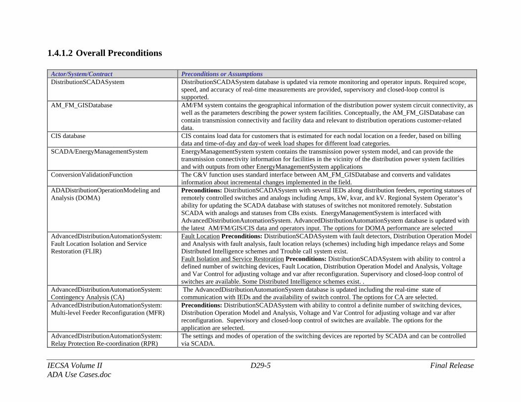
1.4.1.2 Overall Preconditions
Actor/System/Contract Preconditions or Assumptions DistributionSCADASystem DistributionSCADASystem database is updated via remote monitoring and operator inputs. Required scope,
speed, and accuracy of real-time measurements are provided, supervisory and closed-loop control is supported.
AM_FM_GISDatabase AM/FM system contains the geographical information of the distribution power system circuit connectivity, as well as the parameters describing the power system facilities. Conceptually, the AM_FM_GISDatabase can contain transmission connectivity and facility data and relevant to distribution operations customer-related data.
CIS database CIS contains load data for customers that is estimated for each nodal location on a feeder, based on billing data and time-of-day and day-of week load shapes for different load categories.
SCADA/EnergyManagementSystem EnergyManagementSystem system contains the transmission power system model, and can provide the transmission connectivity information for facilities in the vicinity of the distribution power system facilities and with outputs from other EnergyManagementSystem applications
ConversionValidationFunction The C&V function uses standard interface between AM_FM_GISDatabase and converts and validates information about incremental changes implemented in the field.
ADADistributionOperationModeling and Analysis (DOMA)
Preconditions: DistributionSCADASystem with several IEDs along distribution feeders, reporting statuses of remotely controlled switches and analogs including Amps, kW, kvar, and kV. Regional System Operator’s ability for updating the SCADA database with statuses of switches not monitored remotely. Substation SCADA with analogs and statuses from CBs exists. EnergyManagementSystem is interfaced with AdvancedDistributionAutomationSystem. AdvancedDistributionAutomationSystem database is updated with the latest AM/FM/GIS/CIS data and operators input. The options for DOMA performance are selected
AdvancedDistributionAutomationSystem: Fault Location Isolation and Service Restoration (FLIR)
Fault Location Preconditions: DistributionSCADASystem with fault detectors, Distribution Operation Model and Analysis with fault analysis, fault location relays (schemes) including high impedance relays and Some Distributed Intelligence schemes and Trouble call system exist. Fault Isolation and Service Restoration Preconditions: DistributionSCADASystem with ability to control a defined number of switching devices, Fault Location, Distribution Operation Model and Analysis, Voltage and Var Control for adjusting voltage and var after reconfiguration. Supervisory and closed-loop control of switches are available. Some Distributed Intelligence schemes exist. .
AdvancedDistributionAutomationSystem: Contingency Analysis (CA)
The AdvancedDistributionAutomationSystem database is updated including the real-time state of communication with IEDs and the availability of switch control. The options for CA are selected.
AdvancedDistributionAutomationSystem: Multi-level Feeder Reconfiguration (MFR)
Preconditions: DistributionSCADASystem with ability to control a definite number of switching devices, Distribution Operation Model and Analysis, Voltage and Var Control for adjusting voltage and var after reconfiguration. Supervisory and closed-loop control of switches are available. The options for the application are selected.
AdvancedDistributionAutomationSystem: Relay Protection Re-coordination (RPR)
The settings and modes of operation of the switching devices are reported by SCADA and can be controlled via SCADA.
IECSA Volume II D29-6 Final Release ADA Use Cases.doc
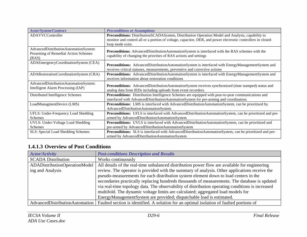
Actor/System/Contract Preconditions or Assumptions ADAVVCController Preconditions: DistributionSCADASystem, Distribution Operation Model and Analysis, capability to
monitor and control all or a portion of voltage, capacitor, DER, and power electronic controllers in closed-loop mode exist.
AdvancedDistributionAutomationSystem: Prearming of Remedial Action Schemes (RAS)
Preconditions: AdvancedDistributionAutomationSystem is interfaced with the RAS schemes with the capability of changing the priorities of RAS actions and settings
ADAEmergencyCoordinationSystem (CEA) Preconditions: AdvancedDistributionAutomationSystem is interfaced with EnergyManagementSystem and receives critical statuses, measurements, preventive and corrective actions
ADARestorationCoordinationSystem (CRA) Preconditions: AdvancedDistributionAutomationSystem is interfaced with EnergyManagementSystem and receives information about restoration conditions
AdvancedDistributionAutomationSystem: Intelligent Alarm Processing (IAP) Preconditions: AdvancedDistributionAutomationSystem receives synchronized (time stamped) status and
analog data from IEDs including uploads from event recorders. Distributed Intelligence Schemes Preconditions: Distribution Intelligence Schemes are equipped with pear-to-pear communications and
interfaced with AdvancedDistributionAutomationSystem for pre-arming and coordination. LoadManagmentDevice (LMS) Preconditions: LMS is interfaced with AdvancedDistributionAutomationSystem, can be prioritized by
AdvancedDistributionAutomationSystem UFLS: Under-Frequency Load Shedding Schemes
Preconditions: UFLS is interfaced with AdvancedDistributionAutomationSystem, can be prioritized and pre-armed by AdvancedDistributionAutomationSystem
UVLS: Under-Voltage Load Shedding Schemes
Preconditions: UVLS is interfaced with AdvancedDistributionAutomationSystem, can be prioritized and pre-armed by AdvancedDistributionAutomationSystem
SLS: Special Load Shedding Schemes Preconditions: SLS is interfaced with AdvancedDistributionAutomationSystem, can be prioritized and pre-armed by AdvancedDistributionAutomationSystem
1.4.1.3 Overview of Post Conditions Actor/Activity Post-conditions Description and Results SCADA Distribution Works continuously ADADistributionOperationModeling and Analysis
All details of the real-time unbalanced distribution power flow are available for engineering review. The operator is provided with the summary of analysis. Other applications receive the pseudo-measurements for each distribution system element down to load centers in the secondaries practically replacing hundreds thousands of measurements. The database is updated via real-time topology data. The observability of distribution operating conditions is increased multifold. The dynamic voltage limits are calculated; aggregated load models for EnergyManagementSystem are provided; dispatchable load is estimated.
AdvancedDistributionAutomation Faulted section is identified. A solution for an optimal isolation of faulted portions of
IECSA Volume II D29-7 Final Release ADA Use Cases.doc
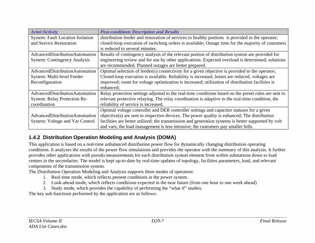
Actor/Activity Post-conditions Description and Results System: Fault Location Isolation and Service Restoration
distribution feeder and restoration of services to healthy portions is provided to the operator; closed-loop execution of switching orders is available; Outage time for the majority of customers is reduced to several minutes.
AdvancedDistributionAutomationSystem: Contingency Analysis
Results of contingency analysis of the relevant portion of distribution system are provided for engineering review and for use by other applications. Expected overload is determined; solutions are recommended. Planned outages are better prepared.
AdvancedDistributionAutomationSystem: Multi-level Feeder Reconfiguration
Optimal selection of feeder(s) connectivity for a given objective is provided to the operator; Closed-loop execution is available. Reliability is increased, losses are reduced, voltages are improved; room for voltage optimization is increased; utilization of distribution facilities is enhanced;
AdvancedDistributionAutomationSystem: Relay Protection Re-coordination
Relay protection settings adjusted to the real-time conditions based on the preset rules are sent to relevant protective relaying. The relay coordination is adaptive to the real-time condition; the reliability of service is increased.
AdvancedDistributionAutomationSystem: Voltage and Var Control
Optimal voltage controller and DER controller settings and capacitor statuses for a given objective(s) are sent to respective devices. The power quality is enhanced; The distribution facilities are better utilized; the transmission and generation systems is better supported by volt and vars; the load management is less intrusive; the customers pay smaller bills.
1.4.2 Distribution Operation Modeling and Analysis (DOMA) This application is based on a real-time unbalanced distribution power flow for dynamically changing distribution operating conditions. It analyzes the results of the power flow simulations and provides the operator with the summary of this analysis. It further provides other applications with pseudo-measurements for each distribution system element from within substations down to load centers in the secondaries. The model is kept up-to-date by real-time updates of topology, facilities parameters, load, and relevant components of the transmission system. The Distribution Operation Modeling and Analysis supports three modes of operation:
1. Real-time mode, which reflects present conditions in the power system. 2. Look-ahead mode, which reflects conditions expected in the near future (from one hour to one week ahead) 3. Study mode, which provides the capability of performing the “what if” studies.
The key sub-functions performed by the application are as follows:
IECSA Volume II D29-8 Final Release ADA Use Cases.doc
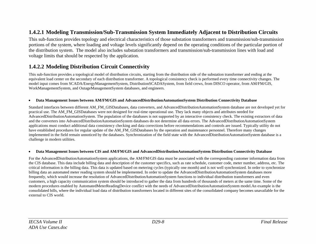
1.4.2.1 Modeling Transmission/Sub-Transmission System Immediately Adjacent to Distribution Circuits This sub-function provides topology and electrical characteristics of those substation transformers and transmission/sub-transmission portions of the system, where loading and voltage levels significantly depend on the operating conditions of the particular portion of the distribution system. The model also includes substation transformers and transmission/sub-transmission lines with load and voltage limits that should be respected by the application.
1.4.2.2 Modeling Distribution Circuit Connectivity This sub-function provides a topological model of distribution circuits, starting from the distribution side of the substation transformer and ending at the equivalent load center on the secondary of each distribution transformer. A topological consistency check is performed every time connectivity changes. The model input comes from SCADA/EnergyManagementSystem, DistributionSCADASystem, from field crews, from DISCO operator, from AM/FM/GIS, WorkManagementSystem, and OutageManagementSystem databases, and engineers.
• Data Management Issues between AM/FM/GIS and AdvancedDistributionAutomationSystem Distribution Connectivity Database
Standard interfaces between different AM_FM_GISDatabases, data converters, and AdvancedDistributionAutomationSystem database are not developed yet for practical use. The AM_FM_GISDatabases were not designed for real-time operational use. They lack many objects and attributes needed for AdvancedDistributionAutomationSystem. The population of the databases is not supported by an interactive consistency check. The existing extractors of data and the converters into AdvancedDistributionAutomationSystem databases do not determine all data errors. The AdvancedDistributionAutomationSystem applications must conduct additional data consistency checking and data corrections before recommendations and controls are issued. Typically utility do not have established procedures for regular update of the AM_FM_GISDatabases by the operation and maintenance personnel. Therefore many changes implemented in the field remain unnoticed by the databases. Synchronization of the field state with the AdvancedDistributionAutomationSystem database is a challenge in modern utilities.
• Data Management Issues between CIS and AM/FM/GIS and AdvancedDistributionAutomationSystem Distribution Connectivity Database
For the AdvancedDistributionAutomationSystem applications, the AM/FM/GIS data must be associated with the corresponding customer information data from the CIS database. This data include billing data and description of the customer specifics, such as rate schedule, customer code, meter number, address, etc. The critical information is the billing data. This data is updated based on metering cycles (typically one month) and is not well synchronized. In order to synchronize billing data an automated meter reading system should be implemented. In order to update the AdvancedDistributionAutomationSystem databases more frequently, which would increase the resolution of AdvancedDistributionAutomationSystem functions to individual distribution transformers and even customers, a high capacity communication system should be introduced to gather the data from hundreds of thousands of meters at the same time. Some of the modern procedures enabled by AutomatedMeterReadingDevice conflict with the needs of AdvancedDistributionAutomationSystem model.An example is the consolidated bills, where the individual load data of distribution transformers located in different sites of the consolidated company becomes unavailable for the external to CIS world.
IECSA Volume II D29-9 Final Release ADA Use Cases.doc
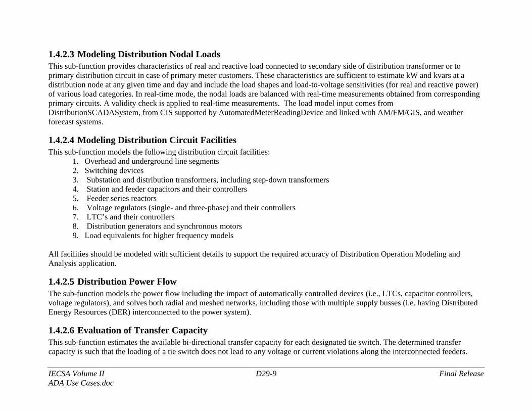
1.4.2.3 Modeling Distribution Nodal Loads This sub-function provides characteristics of real and reactive load connected to secondary side of distribution transformer or to primary distribution circuit in case of primary meter customers. These characteristics are sufficient to estimate kW and kvars at a distribution node at any given time and day and include the load shapes and load-to-voltage sensitivities (for real and reactive power) of various load categories. In real-time mode, the nodal loads are balanced with real-time measurements obtained from corresponding primary circuits. A validity check is applied to real-time measurements. The load model input comes from DistributionSCADASystem, from CIS supported by AutomatedMeterReadingDevice and linked with AM/FM/GIS, and weather forecast systems.
1.4.2.4 Modeling Distribution Circuit Facilities This sub-function models the following distribution circuit facilities:
1. Overhead and underground line segments 2. Switching devices 3. Substation and distribution transformers, including step-down transformers 4. Station and feeder capacitors and their controllers 5. Feeder series reactors 6. Voltage regulators (single- and three-phase) and their controllers 7. LTC’s and their controllers 8. Distribution generators and synchronous motors 9. Load equivalents for higher frequency models
All facilities should be modeled with sufficient details to support the required accuracy of Distribution Operation Modeling and Analysis application.
1.4.2.5 Distribution Power Flow The sub-function models the power flow including the impact of automatically controlled devices (i.e., LTCs, capacitor controllers, voltage regulators), and solves both radial and meshed networks, including those with multiple supply busses (i.e. having Distributed Energy Resources (DER) interconnected to the power system).
1.4.2.6 Evaluation of Transfer Capacity This sub-function estimates the available bi-directional transfer capacity for each designated tie switch. The determined transfer capacity is such that the loading of a tie switch does not lead to any voltage or current violations along the interconnected feeders.
IECSA Volume II D29-10 Final Release ADA Use Cases.doc
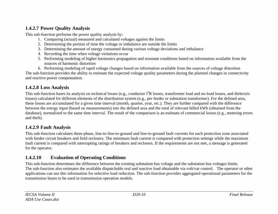
1.4.2.7 Power Quality Analysis This sub-function performs the power quality analysis by:
1. Comparing (actual) measured and calculated voltages against the limits 2. Determining the portion of time the voltage or imbalance are outside the limits 3. Determining the amount of energy consumed during various voltage deviations and imbalance 4. Recording the time when voltage violations occur 5. Performing modeling of higher harmonics propagation and resonant conditions based on information available from the
sources of harmonic distortion 6. Performing modeling of rapid voltage changes based on information available from the sources of voltage distortion
The sub-function provides the ability to estimate the expected voltage quality parameters during the planned changes in connectivity and reactive power compensation.
1.4.2.8 Loss Analysis This sub-function bases its analysis on technical losses (e.g., conductor I2R losses, transformer load and no-load losses, and dielectric losses) calculated for different elements of the distribution system (e.g., per feeder or substation transformer). For the defined area, these losses are accumulated for a given time interval (month, quarter, year, etc.). They are further compared with the difference between the energy input (based on measurements) into the defined area and the total of relevant billed kWh (obtained from the database), normalized to the same time interval. The result of the comparison is an estimate of commercial losses (e.g., metering errors and theft).
1.4.2.9 Fault Analysis This sub-function calculates three-phase, line-to-line-to-ground and line-to-ground fault currents for each protection zone associated with feeder circuit breakers and field reclosers. The minimum fault current is compared with protection settings while the maximum fault current is compared with interrupting ratings of breakers and reclosers. If the requirements are not met, a message is generated for the operator.
1.4.2.10 Evaluation of Operating Conditions This sub-function determines the difference between the existing substation bus voltage and the substation bus voltages limits. The sub-function also estimates the available dispatchable real and reactive load obtainable via volt/var control. The operator or other applications can use this information for selective load reduction. The sub-function provides aggregated operational parameters for the transmission buses to be used in transmission operation models.
IECSA Volume II D29-11 Final Release ADA Use Cases.doc
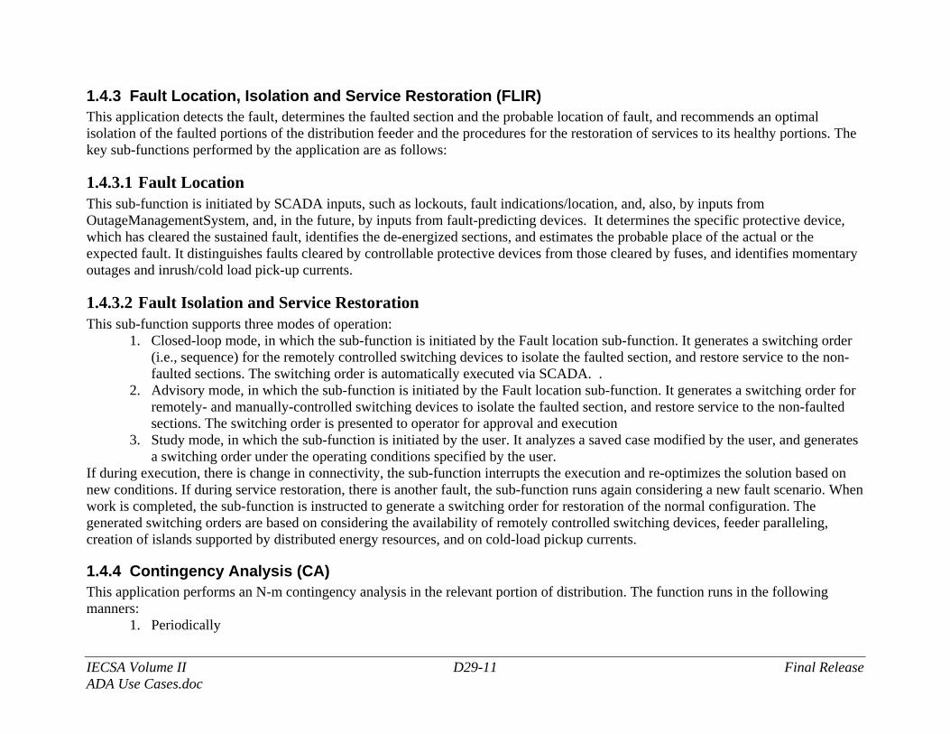
1.4.3 Fault Location, Isolation and Service Restoration (FLIR) This application detects the fault, determines the faulted section and the probable location of fault, and recommends an optimal isolation of the faulted portions of the distribution feeder and the procedures for the restoration of services to its healthy portions. The key sub-functions performed by the application are as follows:
1.4.3.1 Fault Location This sub-function is initiated by SCADA inputs, such as lockouts, fault indications/location, and, also, by inputs from OutageManagementSystem, and, in the future, by inputs from fault-predicting devices. It determines the specific protective device, which has cleared the sustained fault, identifies the de-energized sections, and estimates the probable place of the actual or the expected fault. It distinguishes faults cleared by controllable protective devices from those cleared by fuses, and identifies momentary outages and inrush/cold load pick-up currents.
1.4.3.2 Fault Isolation and Service Restoration This sub-function supports three modes of operation:
1. Closed-loop mode, in which the sub-function is initiated by the Fault location sub-function. It generates a switching order (i.e., sequence) for the remotely controlled switching devices to isolate the faulted section, and restore service to the non-faulted sections. The switching order is automatically executed via SCADA. .
2. Advisory mode, in which the sub-function is initiated by the Fault location sub-function. It generates a switching order for remotely- and manually-controlled switching devices to isolate the faulted section, and restore service to the non-faulted sections. The switching order is presented to operator for approval and execution
3. Study mode, in which the sub-function is initiated by the user. It analyzes a saved case modified by the user, and generates a switching order under the operating conditions specified by the user.
If during execution, there is change in connectivity, the sub-function interrupts the execution and re-optimizes the solution based on new conditions. If during service restoration, there is another fault, the sub-function runs again considering a new fault scenario. When work is completed, the sub-function is instructed to generate a switching order for restoration of the normal configuration. The generated switching orders are based on considering the availability of remotely controlled switching devices, feeder paralleling, creation of islands supported by distributed energy resources, and on cold-load pickup currents.
1.4.4 Contingency Analysis (CA) This application performs an N-m contingency analysis in the relevant portion of distribution. The function runs in the following manners:
1. Periodically
IECSA Volume II D29-12 Final Release ADA Use Cases.doc
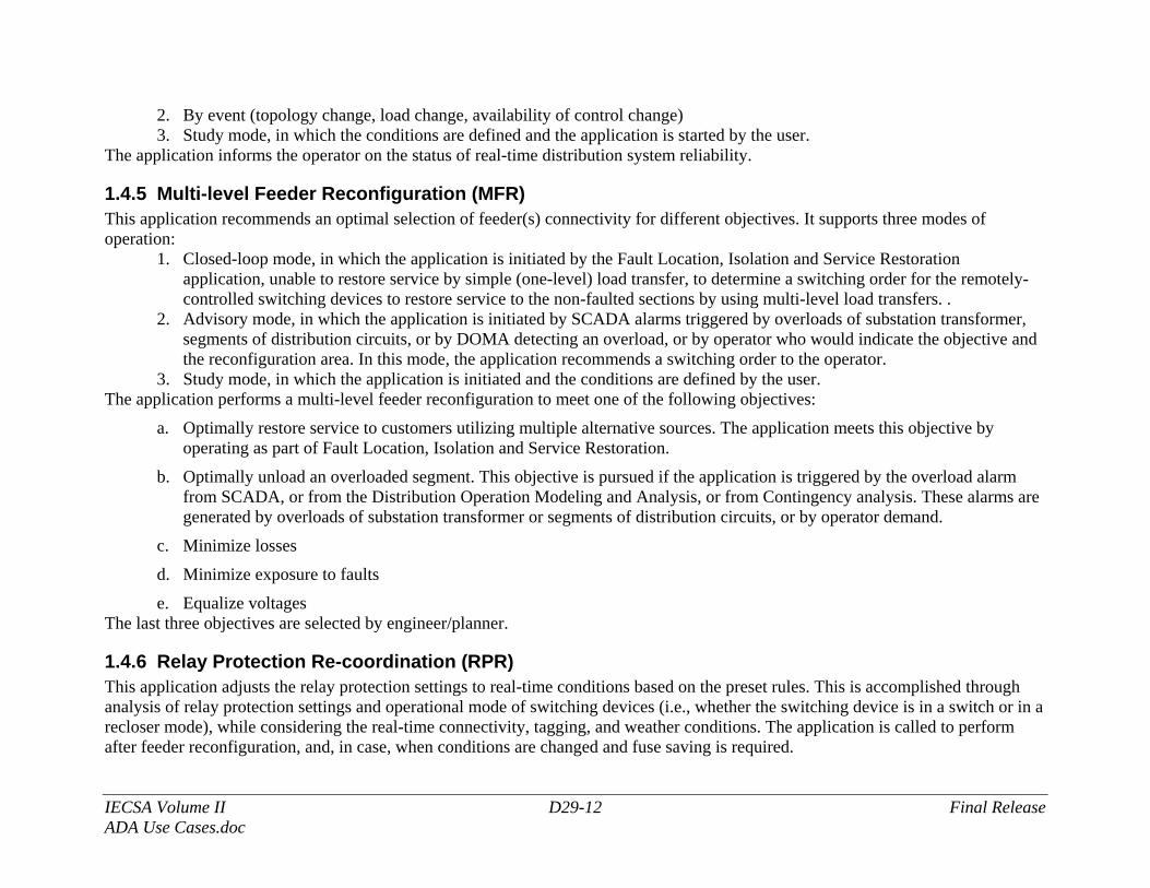
2. By event (topology change, load change, availability of control change) 3. Study mode, in which the conditions are defined and the application is started by the user.
The application informs the operator on the status of real-time distribution system reliability.
1.4.5 Multi-level Feeder Reconfiguration (MFR) This application recommends an optimal selection of feeder(s) connectivity for different objectives. It supports three modes of operation:
1. Closed-loop mode, in which the application is initiated by the Fault Location, Isolation and Service Restoration application, unable to restore service by simple (one-level) load transfer, to determine a switching order for the remotely-controlled switching devices to restore service to the non-faulted sections by using multi-level load transfers. .
2. Advisory mode, in which the application is initiated by SCADA alarms triggered by overloads of substation transformer, segments of distribution circuits, or by DOMA detecting an overload, or by operator who would indicate the objective and the reconfiguration area. In this mode, the application recommends a switching order to the operator.
3. Study mode, in which the application is initiated and the conditions are defined by the user. The application performs a multi-level feeder reconfiguration to meet one of the following objectives:
a. Optimally restore service to customers utilizing multiple alternative sources. The application meets this objective by operating as part of Fault Location, Isolation and Service Restoration.
b. Optimally unload an overloaded segment. This objective is pursued if the application is triggered by the overload alarm from SCADA, or from the Distribution Operation Modeling and Analysis, or from Contingency analysis. These alarms are generated by overloads of substation transformer or segments of distribution circuits, or by operator demand.
c. Minimize losses
d. Minimize exposure to faults
e. Equalize voltages The last three objectives are selected by engineer/planner.
1.4.6 Relay Protection Re-coordination (RPR) This application adjusts the relay protection settings to real-time conditions based on the preset rules. This is accomplished through analysis of relay protection settings and operational mode of switching devices (i.e., whether the switching device is in a switch or in a recloser mode), while considering the real-time connectivity, tagging, and weather conditions. The application is called to perform after feeder reconfiguration, and, in case, when conditions are changed and fuse saving is required.
IECSA Volume II D29-13 Final Release ADA Use Cases.doc
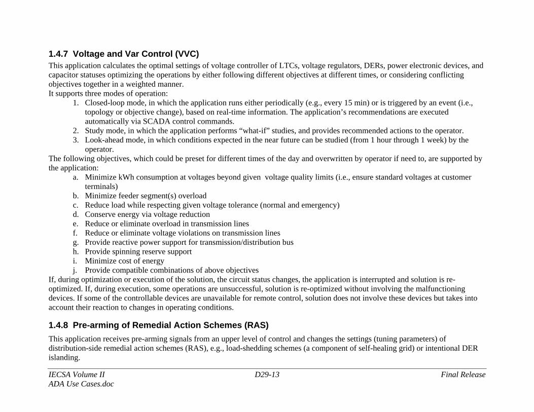
1.4.7 Voltage and Var Control (VVC) This application calculates the optimal settings of voltage controller of LTCs, voltage regulators, DERs, power electronic devices, and capacitor statuses optimizing the operations by either following different objectives at different times, or considering conflicting objectives together in a weighted manner. It supports three modes of operation:
1. Closed-loop mode, in which the application runs either periodically (e.g., every 15 min) or is triggered by an event (i.e., topology or objective change), based on real-time information. The application’s recommendations are executed automatically via SCADA control commands.
2. Study mode, in which the application performs “what-if” studies, and provides recommended actions to the operator. 3. Look-ahead mode, in which conditions expected in the near future can be studied (from 1 hour through 1 week) by the
operator. The following objectives, which could be preset for different times of the day and overwritten by operator if need to, are supported by the application:
a. Minimize kWh consumption at voltages beyond given voltage quality limits (i.e., ensure standard voltages at customer terminals)
b. Minimize feeder segment(s) overload c. Reduce load while respecting given voltage tolerance (normal and emergency) d. Conserve energy via voltage reduction e. Reduce or eliminate overload in transmission lines f. Reduce or eliminate voltage violations on transmission lines g. Provide reactive power support for transmission/distribution bus h. Provide spinning reserve support i. Minimize cost of energy j. Provide compatible combinations of above objectives
If, during optimization or execution of the solution, the circuit status changes, the application is interrupted and solution is re-optimized. If, during execution, some operations are unsuccessful, solution is re-optimized without involving the malfunctioning devices. If some of the controllable devices are unavailable for remote control, solution does not involve these devices but takes into account their reaction to changes in operating conditions.
1.4.8 Pre-arming of Remedial Action Schemes (RAS) This application receives pre-arming signals from an upper level of control and changes the settings (tuning parameters) of distribution-side remedial action schemes (RAS), e.g., load-shedding schemes (a component of self-healing grid) or intentional DER islanding.
IECSA Volume II D29-14 Final Release ADA Use Cases.doc
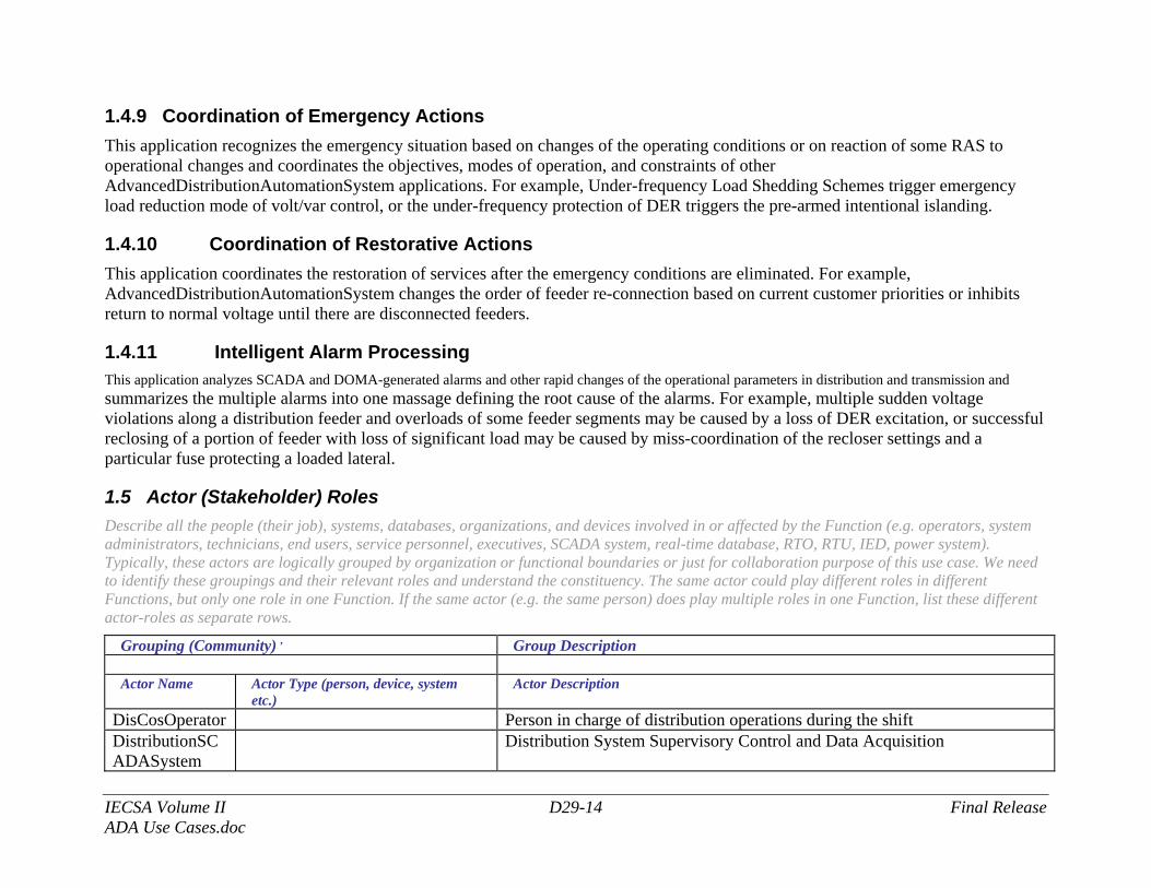
1.4.9 Coordination of Emergency Actions This application recognizes the emergency situation based on changes of the operating conditions or on reaction of some RAS to operational changes and coordinates the objectives, modes of operation, and constraints of other AdvancedDistributionAutomationSystem applications. For example, Under-frequency Load Shedding Schemes trigger emergency load reduction mode of volt/var control, or the under-frequency protection of DER triggers the pre-armed intentional islanding.
1.4.10 Coordination of Restorative Actions This application coordinates the restoration of services after the emergency conditions are eliminated. For example, AdvancedDistributionAutomationSystem changes the order of feeder re-connection based on current customer priorities or inhibits return to normal voltage until there are disconnected feeders.
1.4.11 Intelligent Alarm Processing This application analyzes SCADA and DOMA-generated alarms and other rapid changes of the operational parameters in distribution and transmission and summarizes the multiple alarms into one massage defining the root cause of the alarms. For example, multiple sudden voltage violations along a distribution feeder and overloads of some feeder segments may be caused by a loss of DER excitation, or successful reclosing of a portion of feeder with loss of significant load may be caused by miss-coordination of the recloser settings and a particular fuse protecting a loaded lateral.
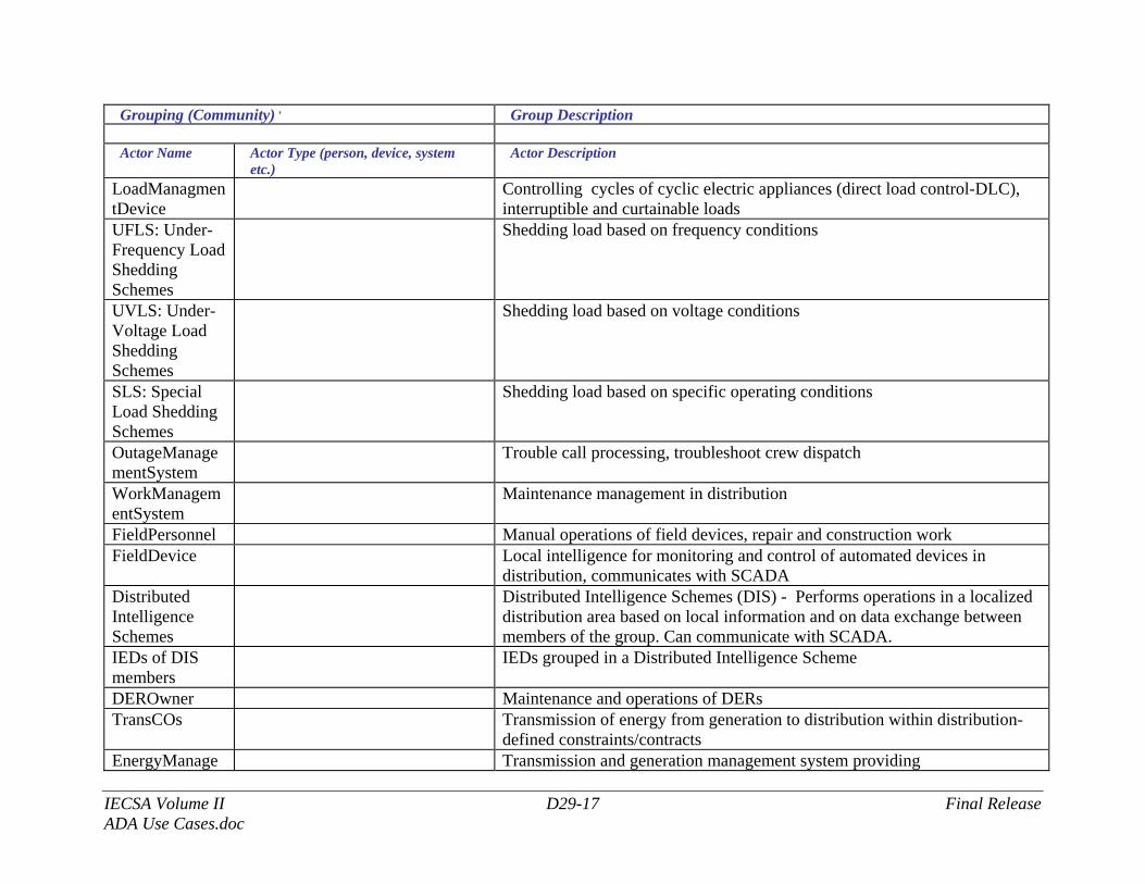
1.5 Actor (Stakeholder) Roles Describe all the people (their job), systems, databases, organizations, and devices involved in or affected by the Function (e.g. operators, system administrators, technicians, end users, service personnel, executives, SCADA system, real-time database, RTO, RTU, IED, power system). Typically, these actors are logically grouped by organization or functional boundaries or just for collaboration purpose of this use case. We need to identify these groupings and their relevant roles and understand the constituency. The same actor could play different roles in different Functions, but only one role in one Function. If the same actor (e.g. the same person) does play multiple roles in one Function, list these different actor-roles as separate rows.
Grouping (Community) , Group Description Actor Name Actor Type (person, device, system
etc.) Actor Description
DisCosOperator Person in charge of distribution operations during the shift DistributionSCADASystem
Distribution System Supervisory Control and Data Acquisition
IECSA Volume II D29-15 Final Release ADA Use Cases.doc
Grouping (Community) , Group Description Actor Name Actor Type (person, device, system
etc.) Actor Description
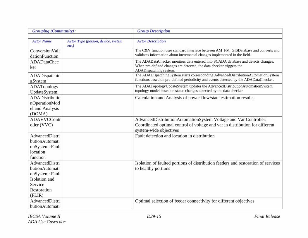
ConversionValidationFunction
The C&V function uses standard interface between AM_FM_GISDatabase and converts and validates information about incremental changes implemented in the field.
ADADataChecker
The ADADataChecker monitors data entered into SCADA database and detects changes. When pre-defined changes are detected, the data checker triggers the ADADispatchingSystem.
ADADispatchingSystem
The ADADispatchingSystem starts corresponding AdvancedDistributionAutomationSystem functions based on pre-defined periodicity and events detected by the ADADataChecker.
ADATopologyUpdateSystem
The ADATopologyUpdateSystem updates the AdvancedDistributionAutomationSystem topology model based on status changes detected by the data checker
ADADistributionOperationModel and Analysis (DOMA)
Calculation and Analysis of power flow/state estimation results
ADAVVCController (VVC)
AdvancedDistributionAutomationSystem Voltage and Var Controller: Coordinated optimal control of voltage and var in distribution for different system-wide objectives
AdvancedDistributionAutomationSystem: Fault location function
Fault detection and location in distribution
AdvancedDistributionAutomationSystem: Fault Isolation and Service Restoration (FLIR)
Isolation of faulted portions of distribution feeders and restoration of services to healthy portions
AdvancedDistributionAutomati
Optimal selection of feeder connectivity for different objectives
IECSA Volume II D29-16 Final Release ADA Use Cases.doc
Grouping (Community) , Group Description Actor Name Actor Type (person, device, system
etc.) Actor Description
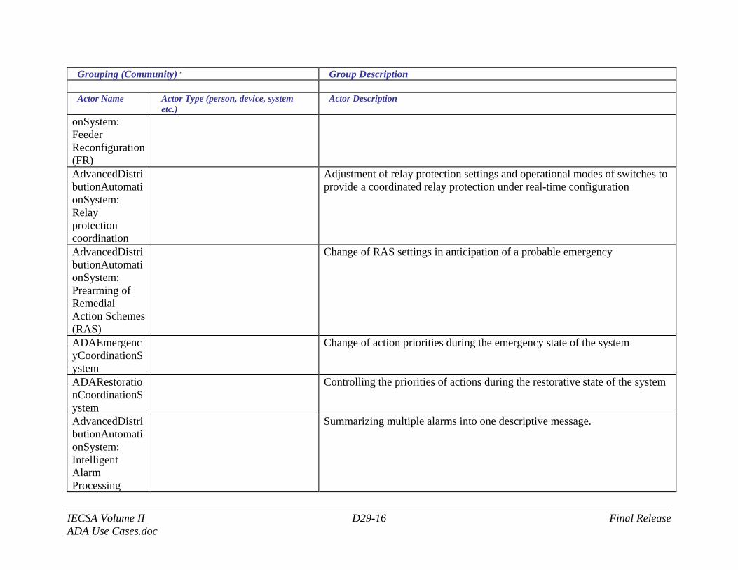
onSystem: Feeder Reconfiguration (FR) AdvancedDistributionAutomationSystem: Relay protection coordination
Adjustment of relay protection settings and operational modes of switches to provide a coordinated relay protection under real-time configuration
AdvancedDistributionAutomationSystem: Prearming of Remedial Action Schemes (RAS)
Change of RAS settings in anticipation of a probable emergency
ADAEmergencyCoordinationSystem
Change of action priorities during the emergency state of the system
ADARestorationCoordinationSystem
Controlling the priorities of actions during the restorative state of the system
AdvancedDistributionAutomationSystem: Intelligent Alarm Processing
Summarizing multiple alarms into one descriptive message.
IECSA Volume II D29-17 Final Release ADA Use Cases.doc
Grouping (Community) , Group Description Actor Name Actor Type (person, device, system
etc.) Actor Description
LoadManagmentDevice
Controlling cycles of cyclic electric appliances (direct load control-DLC), interruptible and curtainable loads
UFLS: Under-Frequency Load Shedding Schemes
Shedding load based on frequency conditions
UVLS: Under-Voltage Load Shedding Schemes
Shedding load based on voltage conditions
SLS: Special Load Shedding Schemes
Shedding load based on specific operating conditions
OutageManagementSystem
Trouble call processing, troubleshoot crew dispatch
WorkManagementSystem
Maintenance management in distribution
FieldPersonnel Manual operations of field devices, repair and construction work FieldDevice Local intelligence for monitoring and control of automated devices in
distribution, communicates with SCADA Distributed Intelligence Schemes
Distributed Intelligence Schemes (DIS) - Performs operations in a localized distribution area based on local information and on data exchange between members of the group. Can communicate with SCADA.
IEDs of DIS members
IEDs grouped in a Distributed Intelligence Scheme
DEROwner Maintenance and operations of DERs TransCOs Transmission of energy from generation to distribution within distribution-
defined constraints/contracts EnergyManage Transmission and generation management system providing
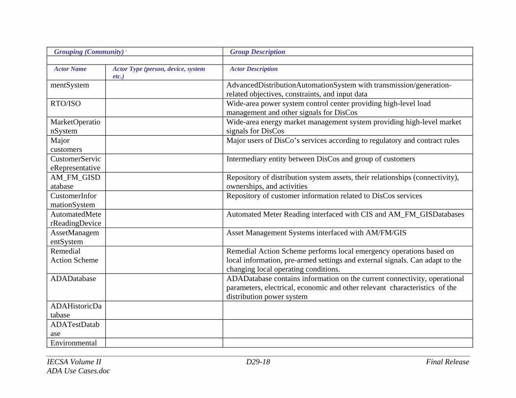
IECSA Volume II D29-18 Final Release ADA Use Cases.doc
Grouping (Community) , Group Description Actor Name Actor Type (person, device, system
etc.) Actor Description
mentSystem AdvancedDistributionAutomationSystem with transmission/generation-related objectives, constraints, and input data
RTO/ISO Wide-area power system control center providing high-level load management and other signals for DisCos
MarketOperationSystem
Wide-area energy market management system providing high-level market signals for DisCos
Major customers
Major users of DisCo’s services according to regulatory and contract rules
CustomerServiceRepresentative
Intermediary entity between DisCos and group of customers
AM_FM_GISDatabase
Repository of distribution system assets, their relationships (connectivity), ownerships, and activities
CustomerInformationSystem
Repository of customer information related to DisCos services
AutomatedMeterReadingDevice
Automated Meter Reading interfaced with CIS and AM_FM_GISDatabases
AssetManagementSystem
Asset Management Systems interfaced with AM/FM/GIS
Remedial Action Scheme
Remedial Action Scheme performs local emergency operations based on local information, pre-armed settings and external signals. Can adapt to the changing local operating conditions.
ADADatabase ADADatabase contains information on the current connectivity, operational parameters, electrical, economic and other relevant characteristics of the distribution power system
ADAHistoricDatabase
ADATestDatabase
Environmental
IECSA Volume II D29-19 Final Release ADA Use Cases.doc
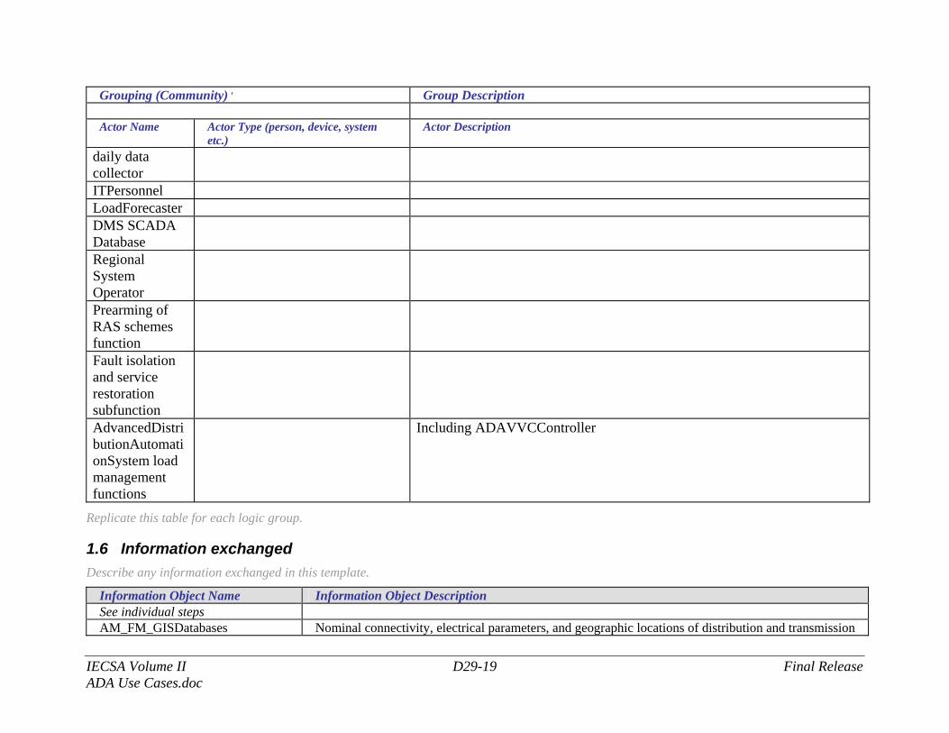
Grouping (Community) , Group Description Actor Name Actor Type (person, device, system
etc.) Actor Description
daily data collector ITPersonnel LoadForecaster DMS SCADA Database
Regional System Operator
Prearming of RAS schemes function
Fault isolation and service restoration subfunction
AdvancedDistributionAutomationSystem load management functions
Including ADAVVCController
Replicate this table for each logic group.
1.6 Information exchanged Describe any information exchanged in this template.
Information Object Name Information Object Description See individual steps AM_FM_GISDatabases Nominal connectivity, electrical parameters, and geographic locations of distribution and transmission
IECSA Volume II D29-20 Final Release ADA Use Cases.doc
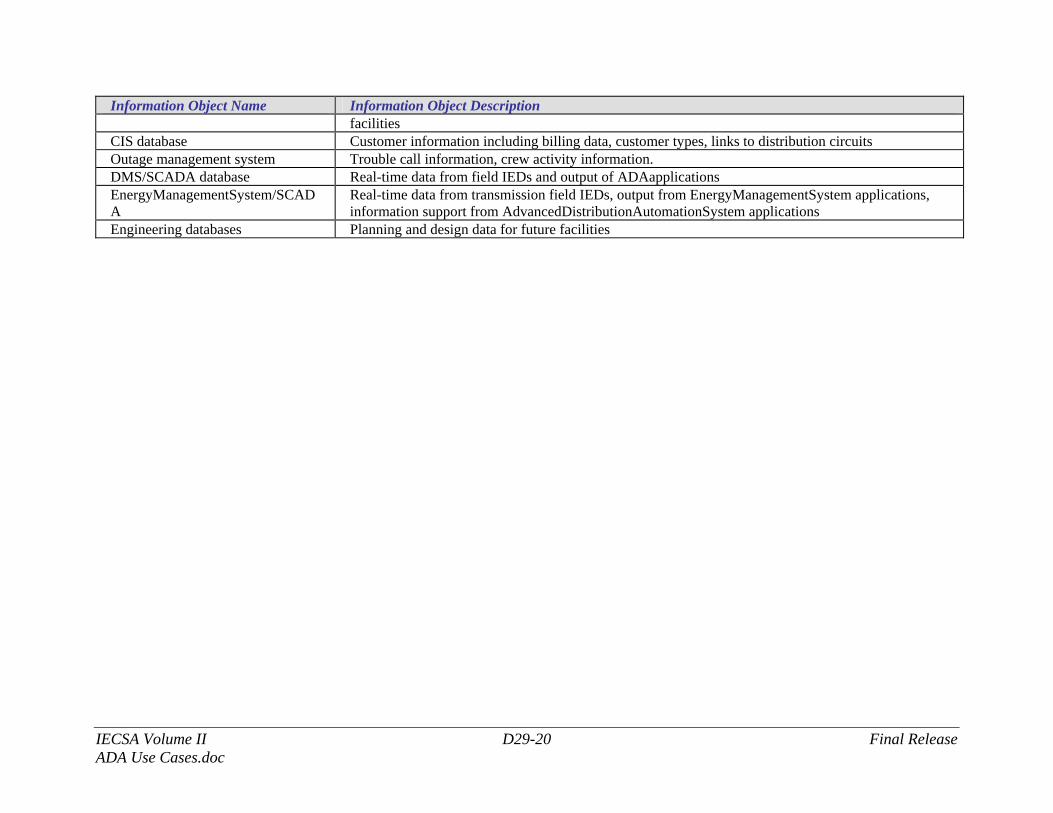
Information Object Name Information Object Description facilities
CIS database Customer information including billing data, customer types, links to distribution circuits Outage management system Trouble call information, crew activity information. DMS/SCADA database Real-time data from field IEDs and output of ADAapplications EnergyManagementSystem/SCADA
Real-time data from transmission field IEDs, output from EnergyManagementSystem applications, information support from AdvancedDistributionAutomationSystem applications
Engineering databases Planning and design data for future facilities
IECSA Volume II D29-21 Final Release ADA Use Cases.doc
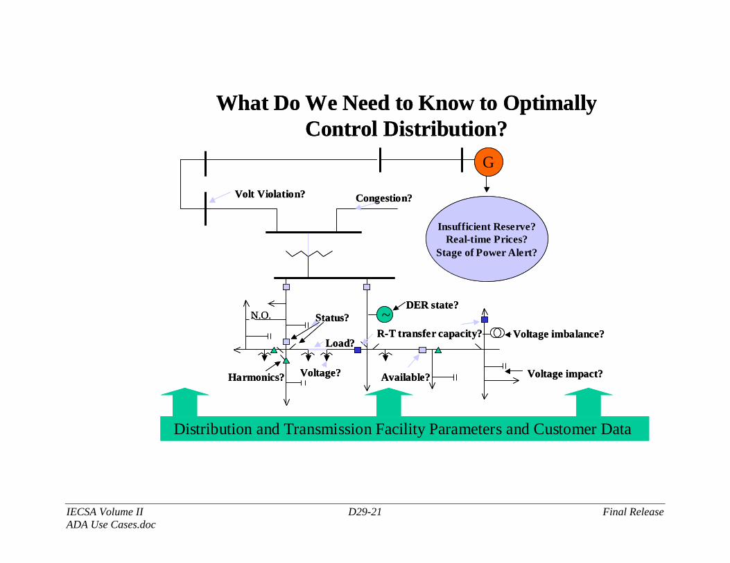
Volt Violation?
What Do We Need to Know to Optimally Control Distribution?
N.O. Status?
Load?
Voltage?
Congestion?
Insufficient Reserve?Real-time Prices?
Stage of Power Alert?
R-T transfer capacity?
Available?Harmonics? Voltage impact?
Voltage imbalance?
G
~DER state?
Distribution and Transmission Facility Parameters and Customer Data
IECSA Volume II D29-22 Final Release ADA Use Cases.doc
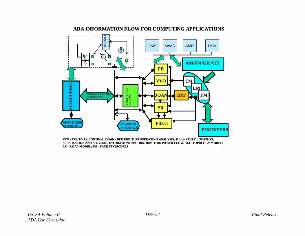
ADA INFORMATION FLOW FOR COMPUTING APPLICATIONS
VVO - VOLT/VAR CONTROL; DOAN - DISTRIBUTION OPERATINO ANALYSIS; FltLct- FAULT LOCATION; SR-ISOLATION AND SERVICE RESTORATION; DPF - DISTRIBUTION POWER FLOW; TM - TOPOLOGY MODEL; LM - LOAD MODEL; FM - FACILITY MODELS
SCA
DA
/EM
S
TMLM
FMDPFDOAN
VVO
FltLct
SR
DIS
PAT C
HIN
G
RO
UT
INESCADA-ADA-SCADA
INTERFACES
AM/FM/GIS/CIS
ENGINEERSENGINEERINTERFACE
DISPATCHERINTERFACE
DER
Dis
tribu
ted
Inte
llige
nce
OMS WMS AMR DSM
FR
ADA INFORMATION FLOW FOR COMPUTING APPLICATIONS
VVO - VOLT/VAR CONTROL; DOAN - DISTRIBUTION OPERATINO ANALYSIS; FltLct- FAULT LOCATION; SR-ISOLATION AND SERVICE RESTORATION; DPF - DISTRIBUTION POWER FLOW; TM - TOPOLOGY MODEL; LM - LOAD MODEL; FM - FACILITY MODELS
SCA
DA
/EM
S
TMLM
FMDPFDOAN
VVO
FltLct
SR
DIS
PAT C
HIN
G
RO
UT
INESCADA-ADA-SCADA
INTERFACES
AM/FM/GIS/CIS
ENGINEERSENGINEERINTERFACE
DISPATCHERINTERFACE
DER
Dis
tribu
ted
Inte
llige
nce
DER
Dis
tribu
ted
Inte
llige
nce
DER
Dis
tribu
ted
Inte
llige
nce
OMS WMS AMR DSM
FR
IECSA Volume II D29-23 Final Release ADA Use Cases.doc
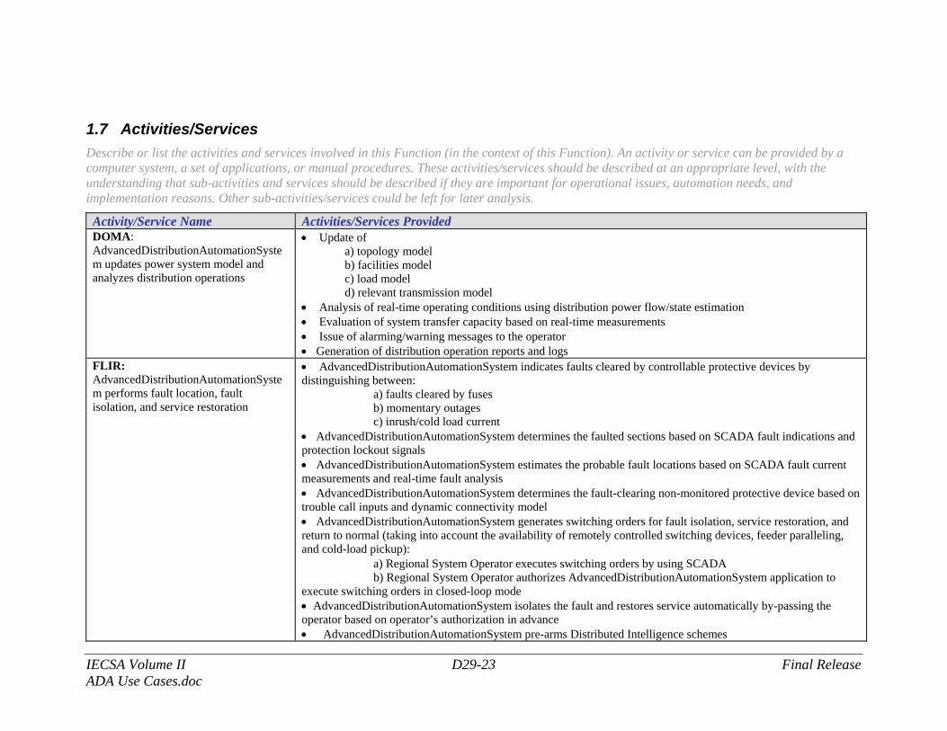
1.7 Activities/Services Describe or list the activities and services involved in this Function (in the context of this Function). An activity or service can be provided by a computer system, a set of applications, or manual procedures. These activities/services should be described at an appropriate level, with the understanding that sub-activities and services should be described if they are important for operational issues, automation needs, and implementation reasons. Other sub-activities/services could be left for later analysis.
Activity/Service Name Activities/Services Provided DOMA: AdvancedDistributionAutomationSystem updates power system model and analyzes distribution operations
• Update of a) topology model b) facilities model c) load model d) relevant transmission model
• Analysis of real-time operating conditions using distribution power flow/state estimation • Evaluation of system transfer capacity based on real-time measurements • Issue of alarming/warning messages to the operator • Generation of distribution operation reports and logs
FLIR: AdvancedDistributionAutomationSystem performs fault location, fault isolation, and service restoration
• AdvancedDistributionAutomationSystem indicates faults cleared by controllable protective devices by distinguishing between: a) faults cleared by fuses b) momentary outages c) inrush/cold load current • AdvancedDistributionAutomationSystem determines the faulted sections based on SCADA fault indications and protection lockout signals • AdvancedDistributionAutomationSystem estimates the probable fault locations based on SCADA fault current measurements and real-time fault analysis • AdvancedDistributionAutomationSystem determines the fault-clearing non-monitored protective device based on trouble call inputs and dynamic connectivity model • AdvancedDistributionAutomationSystem generates switching orders for fault isolation, service restoration, and return to normal (taking into account the availability of remotely controlled switching devices, feeder paralleling, and cold-load pickup): a) Regional System Operator executes switching orders by using SCADA b) Regional System Operator authorizes AdvancedDistributionAutomationSystem application to execute switching orders in closed-loop mode • AdvancedDistributionAutomationSystem isolates the fault and restores service automatically by-passing the operator based on operator’s authorization in advance • AdvancedDistributionAutomationSystem pre-arms Distributed Intelligence schemes
IECSA Volume II D29-24 Final Release ADA Use Cases.doc
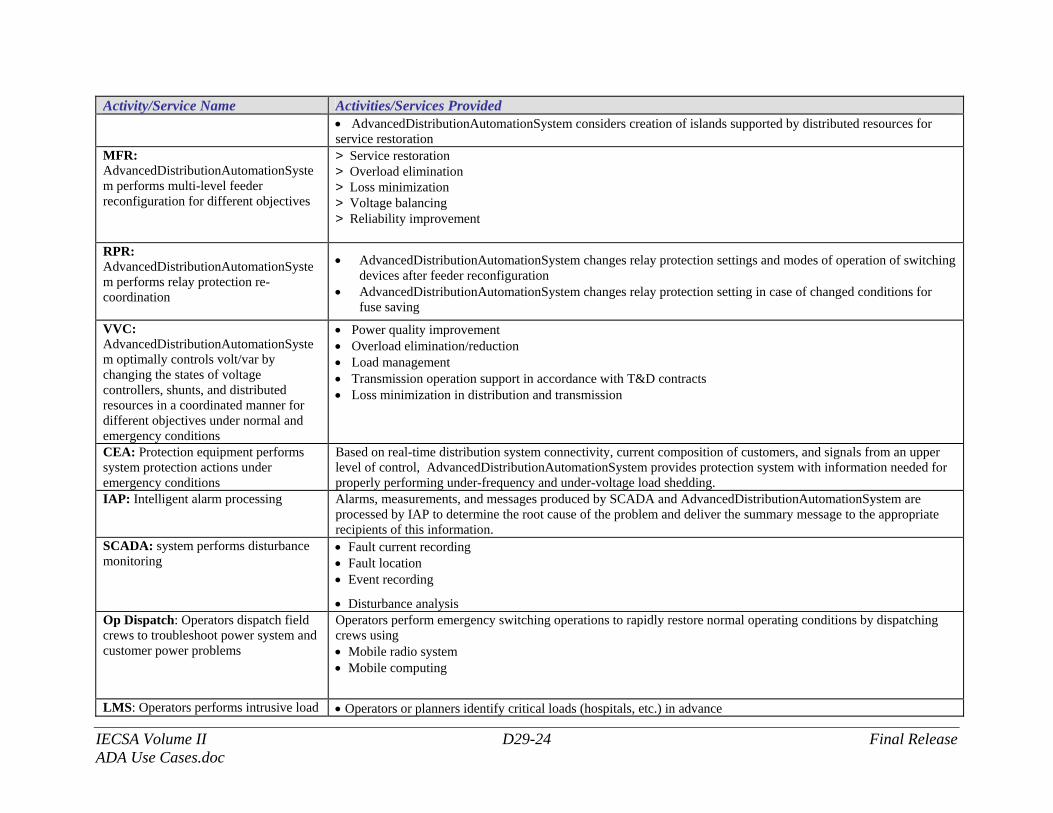
Activity/Service Name Activities/Services Provided • AdvancedDistributionAutomationSystem considers creation of islands supported by distributed resources for service restoration
MFR: AdvancedDistributionAutomationSystem performs multi-level feeder reconfiguration for different objectives
> Service restoration > Overload elimination > Loss minimization > Voltage balancing > Reliability improvement
RPR: AdvancedDistributionAutomationSystem performs relay protection re-coordination
• AdvancedDistributionAutomationSystem changes relay protection settings and modes of operation of switching devices after feeder reconfiguration
• AdvancedDistributionAutomationSystem changes relay protection setting in case of changed conditions for fuse saving
VVC: AdvancedDistributionAutomationSystem optimally controls volt/var by changing the states of voltage controllers, shunts, and distributed resources in a coordinated manner for different objectives under normal and emergency conditions
• Power quality improvement • Overload elimination/reduction • Load management • Transmission operation support in accordance with T&D contracts • Loss minimization in distribution and transmission
CEA: Protection equipment performs system protection actions under emergency conditions
Based on real-time distribution system connectivity, current composition of customers, and signals from an upper level of control, AdvancedDistributionAutomationSystem provides protection system with information needed for properly performing under-frequency and under-voltage load shedding.
IAP: Intelligent alarm processing
Alarms, measurements, and messages produced by SCADA and AdvancedDistributionAutomationSystem are processed by IAP to determine the root cause of the problem and deliver the summary message to the appropriate recipients of this information.
SCADA: system performs disturbance monitoring
• Fault current recording • Fault location • Event recording
• Disturbance analysis Op Dispatch: Operators dispatch field crews to troubleshoot power system and customer power problems
Operators perform emergency switching operations to rapidly restore normal operating conditions by dispatching crews using • Mobile radio system • Mobile computing
LMS: Operators performs intrusive load • Operators or planners identify critical loads (hospitals, etc.) in advance
IECSA Volume II D29-25 Final Release ADA Use Cases.doc
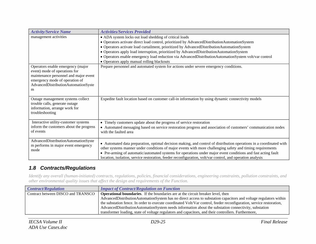
Activity/Service Name Activities/Services Provided management activities • ΑDA system locks out load shedding of critical loads
• Operators activate direct load control, prioritized by AdvancedDistributionAutomationSystem • Operators activate load curtailment, prioritized by AdvancedDistributionAutomationSystem • Operators apply load interruption, prioritized by AdvancedDistributionAutomationSystem • Operators enable emergency load reduction via AdvancedDistributionAutomationSystem volt/var control • Operators apply manual rolling blackouts
Operators enable emergency (major event) mode of operations for maintenance personnel and major event emergency mode of operation of AdvancedDistributionAutomationSystem
Prepare personnel and automated system for actions under severe emergency conditions.
Outage management systems collect trouble calls, generate outage information, arrange work for troubleshooting
Expedite fault location based on customer call-in information by using dynamic connectivity models
Interactive utility-customer systems inform the customers about the progress of events
• Timely customers update about the progress of service restoration • Automated messaging based on service restoration progress and association of customers’ communication nodes with the faulted area
AdvancedDistributionAutomationSystem performs in major event emergency mode
• Automated data preparation, optimal decision making, and control of distribution operations in a coordinated with other systems manner under conditions of major events with more challenging safety and timing requirements • Pre-arming of automatic/automated systems for operations under major event conditions and fast acting fault location, isolation, service restoration, feeder reconfiguration, volt/var control, and operation analysis
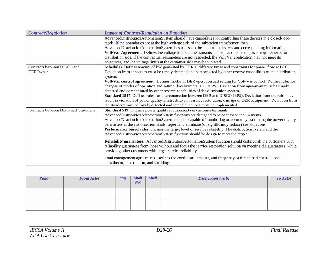
1.8 Contracts/Regulations Identify any overall (human-initiated) contracts, regulations, policies, financial considerations, engineering constraints, pollution constraints, and other environmental quality issues that affect the design and requirements of the Function.
Contract/Regulation Impact of Contract/Regulation on Function Contract between DISCO and TRANSCO Operational boundaries. If the boundaries are at the circuit breaker level, then
AdvancedDistributionAutomationSystem has no direct access to substation capacitors and voltage regulators within the substation fence. In order to execute coordinated Volt/Var control, feeder reconfiguration, service restoration, AdvancedDistributionAutomationSystem needs information about the substation connectivity, substation transformer loading, state of voltage regulators and capacitors, and their controllers. Furthermore,
IECSA Volume II D29-26 Final Release ADA Use Cases.doc
Contract/Regulation Impact of Contract/Regulation on Function AdvancedDistributionAutomationSystem should have capabilities for controlling these devices in a closed-loop mode. If the boundaries are at the high-voltage side of the substation transformer, then AdvancedDistributionAutomationSystem has access to the substation devices and corresponding information. Volt/Var Agreement. Defines the voltage limits at the transmission side and reactive power requirements for distribution side. If the contractual parameters are not respected, the Volt/Var application may not meet its objectives, and the voltage limits at the customer side may be violated.
Contracts between DISCO and DEROwner
Schedules. Defines amount of kW generated by DER at different times and constraints for power flow at PCC. Deviation from schedules must be timely detected and compensated by other reserve capabilities of the distribution system. Volt/Var control agreement. Defines modes of DER operation and setting for Volt/Var control. Defines rules for changes of modes of operation and setting (local/remote, DER/EPS). Deviation from agreement must be timely detected and compensated by other reserve capabilities of the distribution system. Standard 1547. Defines rules for interconnection between DER and DISCO (EPS). Deviation from the rules may result in violation of power quality limits, delays in service restoration, damage of DER equipment. Deviation from the standard must be timely detected and remedial actions must be implemented.
Contracts between Disco and Customers Standard 519. Defines power quality requirements at customer terminals. AdvancedDistributionAutomationSystem functions are designed to respect these requirements. AdvancedDistributionAutomationSystem must be capable of monitoring or accurately estimating the power quality parameters at the customer terminals, report and eliminate (or significantly reduce) the violations. Performance based rates. Defines the target level of service reliability. The distribution system and the AdvancedDistributionAutomationSystem function should be design to meet the target.
Reliability guarantees. AdvancedDistributionAutomationSystem function should distinguish the customers with reliability guarantees from those without and focus the service restoration solution on meeting the guarantees, while providing other customers with target service reliability.
Load management agreements. Defines the conditions, amount, and frequency of direct load control, load curtailment, interruption, and shedding.
Policy
From Actor
May Shall Not
Shall Description (verb) To Actor
IECSA Volume II D29-27 Final Release ADA Use Cases.doc
Constraint Type Description Applies to
IECSA Volume II D29-28 Final Release ADA Use Cases.doc
2 Step by Step Analysis of Function Describe steps that implement the function. If there is more than one set of steps that are relevant, make a copy of the following section grouping (Preconditions and Assumptions, Steps normal sequence, and Steps alternate or exceptional sequence, Post conditions)
2.1 Distribution Operation Modeling and Analysis (DOMA) Function Name of this sequence.
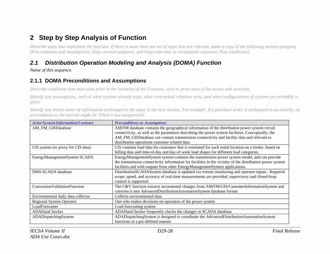
2.1.1 DOMA Preconditions and Assumptions Describe conditions that must exist prior to the initiation of the Function, such as prior state of the actors and activities
Identify any assumptions, such as what systems already exist, what contractual relations exist, and what configurations of systems are probably in place
Identify any initial states of information exchanged in the steps in the next section. For example, if a purchase order is exchanged in an activity, its precondition to the activity might be ‘filled in but unapproved’.
Actor/System/Information/Contract Preconditions or Assumptions AM_FM_GISDatabase AM/FM database contains the geographical information of the distribution power system circuit
connectivity, as well as the parameters describing the power system facilities. Conceptually, the AM_FM_GISDatabase can contain transmission connectivity and facility data and relevant to distribution operations customer-related data.
CIS system (or proxy for CIS data) CIS contains load data for customers that is estimated for each nodal location on a feeder, based on billing data and time-of-day and day-of week load shapes for different load categories.
EnergyManagementSystem SCADA EnergyManagementSystem system contains the transmission power system model, and can provide the transmission connectivity information for facilities in the vicinity of the distribution power system facilities and with outputs from other EnergyManagementSystem applications
DMS SCADA database DistributionSCADASystem database is updated via remote monitoring and operator inputs.. Required scope, speed, and accuracy of real-time measurements are provided, supervisory and closed-loop control is supported.
ConversionValidationFunction The C&V function extracts incremental changes from AM/FM/GIS/CustomerInformationSystem and converts it into AdvancedDistributionAutomationSystem database format
Environmental daily data collector Collects environmental data Regional System Operator One who makes decisions on operation of the power system LoadForecaster Load forecasting system ADADataChecker ADADataChecker frequently checks the changes in SCADA database ADADispatchingSystem ADADispatchingSystem is designed to coordinate the AdvancedDistributionAutomationSystem
functions in a pre-defined manner
IECSA Volume II D29-29 Final Release ADA Use Cases.doc
Actor/System/Information/Contract Preconditions or Assumptions ADATopologyUpdateSystem Checks the topology of the distribution system ITPersonnel Field IT support ADATopologyUpdateSystem ADATopologyUpdateSystem “reconfigures” connectivity models in seconds ADATestDatabase Database containing test data values ADADistributionOperationModeling and Analysis (DOMA)
Preconditions: DistributionSCADASystem with several IEDs along distribution feeders, reporting statuses of remotely controlled switches and analogs including Amps, kW, kvar, and kV. Regional System Operator’s ability for updating the SCADA database with statuses of switches not monitored remotely. Substation SCADA with analogs and statuses from CBs exists. EnergyManagementSystem is interfaced with AdvancedDistributionAutomationSystem. AdvancedDistributionAutomationSystem database is updated with the latest AM/FM and CIS data and operators input. The options for DOMA performance are selected
2.1.2 DOMA Steps – Normal Sequence Describe the normal sequence of events, focusing on steps that identify new types of information or new information exchanges or new interface issues to address. Should the sequence require detailed steps that are also used by other functions, consider creating a new “sub” function, then referring to that “subroutine” in this function. Remember that the focus should be less on the algorithms of the applications and more on the interactions and information flows between “entities”, e.g. people, systems, applications, data bases, etc. There should be a direct link between the narrative and these steps.
The numbering of the sequence steps conveys the order and concurrency and iteration of the steps occur. Using a Dewey Decimal scheme, each level of nested procedure call is separated by a dot ‘.’. Within a level, the sequence number comprises an optional letter and an integer number. The letter specifies a concurrent sequence within the next higher level; all letter sequences are concurrent with other letter sequences. The number specifies the sequencing of messages in a given letter sequence. The absence of a letter is treated as a default 'main sequence' in parallel with the lettered sequences.
Sequence 1: 1.1 - Do step 1 1.2A.1 - In parallel to activity 2 B do step 1
1.2A.2 - In parallel to activity 2 B do step 2 1.2B.1 - In parallel to activity 2 A do step 1 1.2B.2 - In parallel to activity 2 A do step 2 1.3 - Do step 3
1.3.1 - nested step 3.1 1.3.2 - nested step 3.2
Sequence 2:
IECSA Volume II D29-30 Final Release ADA Use Cases.doc
2.1 - Do step 1 2.2 – Do step 2
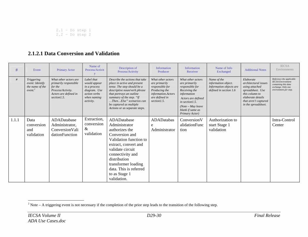
2.1.2.1 Data Conversion and Validation
# Event Primary Actor Name of
Process/Activity
Description of Process/Activity
Information Producer
Information Receiver
Name of Info Exchanged Additional Notes
IECSA Environments
# Triggering event: Identify the name of the event.2
What other actors are primarily responsible for the Process/Activity. Actors are defined in section1.5.
Label that would appear in a process diagram. Use action verbs when naming activity.
Describe the actions that take place in active and present tense. The step should be a descriptive noun/verb phrase that portrays an outline summary of the step. “If …Then…Else” scenarios can be captured as multiple Actions or as separate steps.
What other actors are primarily responsible for Producing the information.Actors are defined in section1.5.
What other actors are primarily responsible for Receiving the information Actors are defined in section1.5. (Note – May leave blank if same as Primary Actor)
Name of the information object. Information objects are defined in section 1.6
Elaborate architectural issues using attached spreadsheet. Use this column to elaborate details that aren’t captured in the spreadsheet.
Reference the applicable IECSA Environment containing this data exchange. Only one environment per step.
1.1.1 Data conversion and validation
ADADatabase Administrator, ConversionValidationFunction
Extraction, conversion & validation
ADADatabase Administrator authorizes the Conversion and Validation function to extract, convert and validate circuit connectivity and distribution transformer loading data. This is referred to as Stage 1 validation.
ADADatabase Administrator
ConversionValidationFunction
Authorization to start Stage 1 validation
Intra-Control Center
2 Note – A triggering event is not necessary if the completion of the prior step leads to the transition of the following step.
IECSA Volume II D29-31 Final Release ADA Use Cases.doc
# Event Primary Actor Name of
Process/Activity
Description of Process/Activity
Information Producer
Information Receiver
Name of Info Exchanged Additional Notes
IECSA Environments
1.1.2 DMS SCADA database, DOMA function
Checking real-time data
The data in the latest download of DMS SCADA data is checked by DOMA function for changes in topology and used to obtain the latest relevant analog data.
DMS SCADA database
DOMA function
DMS real-time analog, status & TLQ data
Intra-Control Center
1.1.3 DOMA function, ADATopologyUpdateSystem
Connectivity change
ADATopologyUpdateSystem prepares changes in connectivity based on the latest DMS SCADA data for updating AdvancedDistributionAutomationSystem database
DOMA function
ADATopologyUpdateSystem
Changes in connectivity
Intra-Control Center
1.1.4 ADATopologyUpdateSystem, ADADatabase
AdvancedDistributionAutomationSystem database update
ADATopologyUpdateSystem updates AdvancedDistributionAutomationSystem database
ADATopologyUpdateSystem
ADADatabase
AdvancedDistributionAutomationSystem database update
Intra-Control Center
1.1.5 AM/FM/GIS Database, ConversionValidationFunction
Extraction, conversion & validation
Conversion and Validation function receives initial (before any corrections) connectivity, billing and facility parameter data.
AM_FM_GISDatabase
ConversionValidationFunction
Initial connectivity, billing and facility parameter data
Intra-Control Center
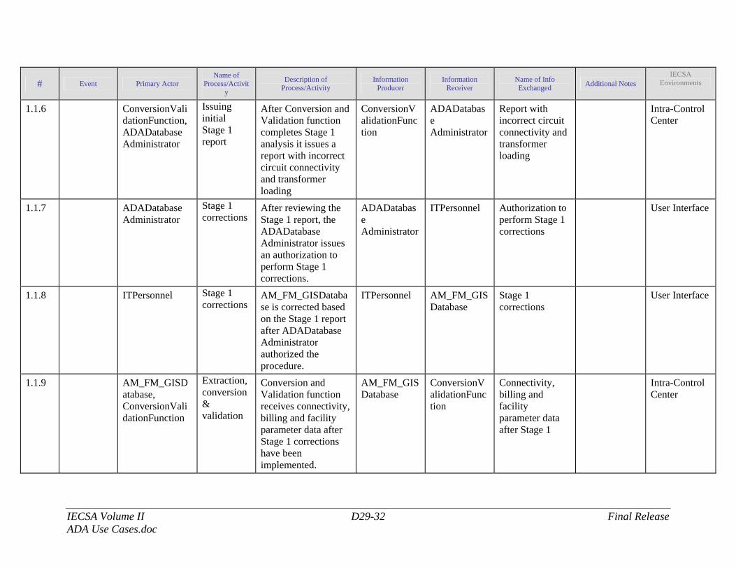
IECSA Volume II D29-32 Final Release ADA Use Cases.doc
# Event Primary Actor Name of
Process/Activity
Description of Process/Activity
Information Producer
Information Receiver
Name of Info Exchanged Additional Notes
IECSA Environments
1.1.6 ConversionValidationFunction, ADADatabase Administrator
Issuing initial Stage 1 report
After Conversion and Validation function completes Stage 1 analysis it issues a report with incorrect circuit connectivity and transformer loading
ConversionValidationFunction
ADADatabase Administrator
Report with incorrect circuit connectivity and transformer loading
Intra-Control Center
1.1.7 ADADatabase Administrator
Stage 1 corrections
After reviewing the Stage 1 report, the ADADatabase Administrator issues an authorization to perform Stage 1 corrections.
ADADatabase Administrator
ITPersonnel Authorization to perform Stage 1 corrections
User Interface
1.1.8 ITPersonnel Stage 1 corrections
AM_FM_GISDatabase is corrected based on the Stage 1 report after ADADatabase Administrator authorized the procedure.
ITPersonnel AM_FM_GISDatabase
Stage 1 corrections
User Interface
1.1.9 AM_FM_GISDatabase, ConversionValidationFunction
Extraction, conversion & validation
Conversion and Validation function receives connectivity, billing and facility parameter data after Stage 1 corrections have been implemented.
AM_FM_GISDatabase
ConversionValidationFunction
Connectivity, billing and facility parameter data after Stage 1
Intra-Control Center
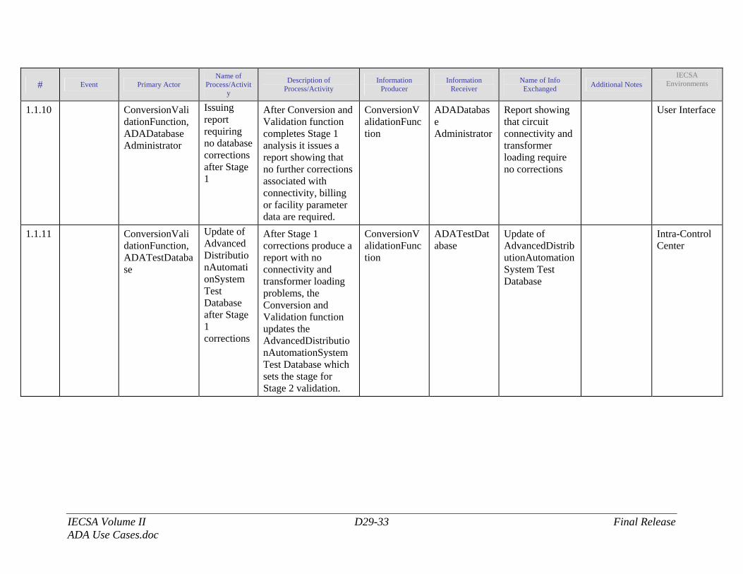
IECSA Volume II D29-33 Final Release ADA Use Cases.doc
# Event Primary Actor Name of
Process/Activity
Description of Process/Activity
Information Producer
Information Receiver
Name of Info Exchanged Additional Notes
IECSA Environments
1.1.10 ConversionValidationFunction, ADADatabase Administrator
Issuing report requiring no database corrections after Stage 1
After Conversion and Validation function completes Stage 1 analysis it issues a report showing that no further corrections associated with connectivity, billing or facility parameter data are required.
ConversionValidationFunction
ADADatabase Administrator
Report showing that circuit connectivity and transformer loading require no corrections
User Interface
1.1.11 ConversionValidationFunction, ADATestDatabase
Update of AdvancedDistributionAutomationSystem Test Database after Stage 1 corrections
After Stage 1 corrections produce a report with no connectivity and transformer loading problems, the Conversion and Validation function updates the AdvancedDistributionAutomationSystem Test Database which sets the stage for Stage 2 validation.
ConversionValidationFunction
ADATestDatabase
Update of AdvancedDistributionAutomationSystem Test Database
Intra-Control Center
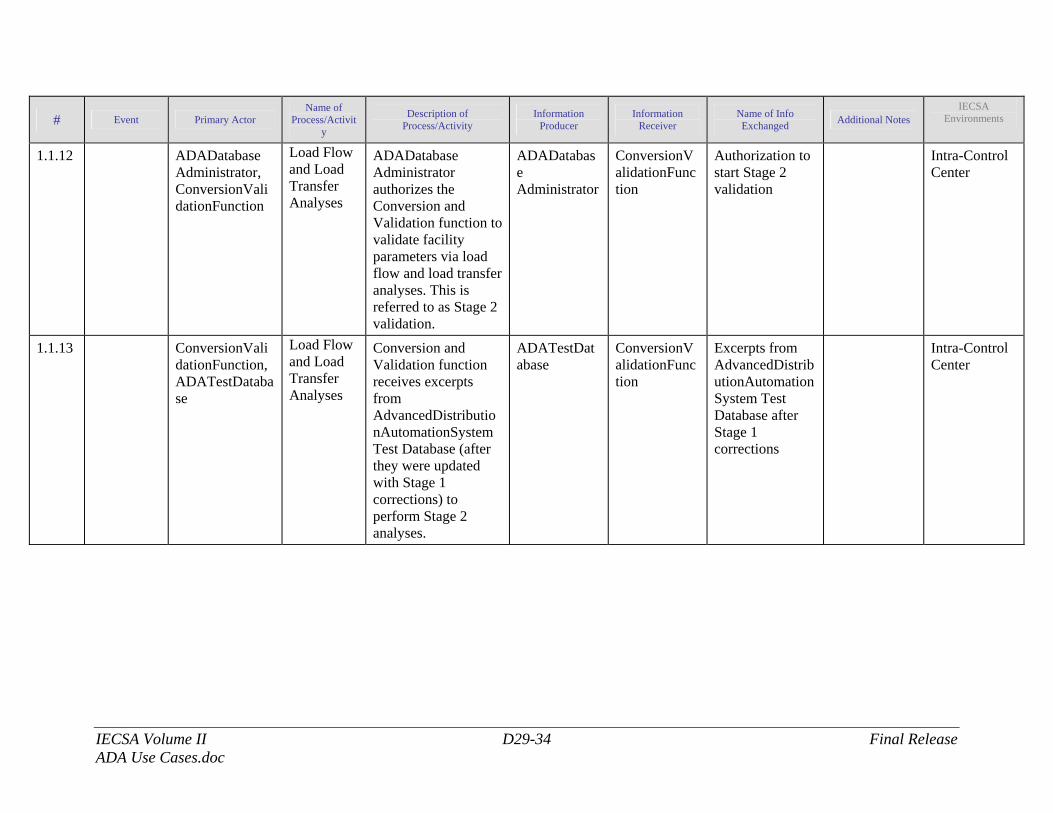
IECSA Volume II D29-34 Final Release ADA Use Cases.doc
# Event Primary Actor Name of
Process/Activity
Description of Process/Activity
Information Producer
Information Receiver
Name of Info Exchanged Additional Notes
IECSA Environments
1.1.12 ADADatabase Administrator, ConversionValidationFunction
Load Flow and Load Transfer Analyses
ADADatabase Administrator authorizes the Conversion and Validation function to validate facility parameters via load flow and load transfer analyses. This is referred to as Stage 2 validation.
ADADatabase Administrator
ConversionValidationFunction
Authorization to start Stage 2 validation
Intra-Control Center
1.1.13 ConversionValidationFunction, ADATestDatabase
Load Flow and Load Transfer Analyses
Conversion and Validation function receives excerpts from AdvancedDistributionAutomationSystem Test Database (after they were updated with Stage 1 corrections) to perform Stage 2 analyses.
ADATestDatabase
ConversionValidationFunction
Excerpts from AdvancedDistributionAutomationSystem Test Database after Stage 1 corrections
Intra-Control Center
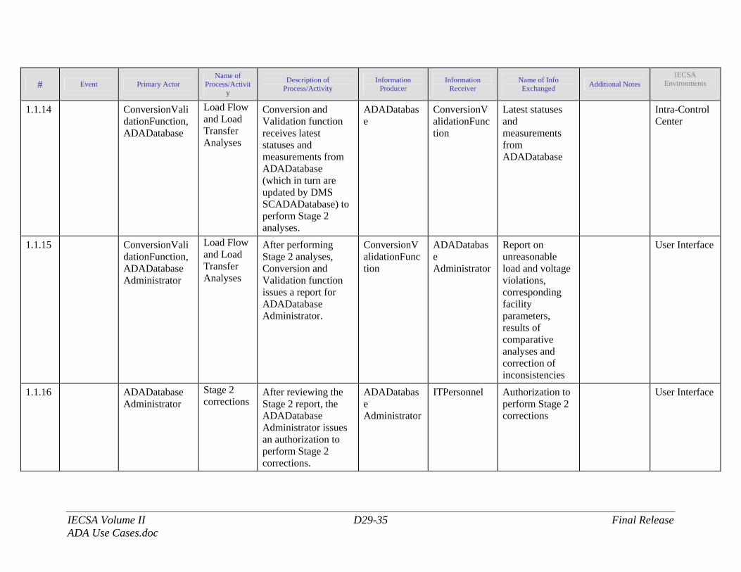
IECSA Volume II D29-35 Final Release ADA Use Cases.doc
# Event Primary Actor Name of
Process/Activity
Description of Process/Activity
Information Producer
Information Receiver
Name of Info Exchanged Additional Notes
IECSA Environments
1.1.14 ConversionValidationFunction, ADADatabase
Load Flow and Load Transfer Analyses
Conversion and Validation function receives latest statuses and measurements from ADADatabase (which in turn are updated by DMS SCADADatabase) to perform Stage 2 analyses.
ADADatabase
ConversionValidationFunction
Latest statuses and measurements from ADADatabase
Intra-Control Center
1.1.15 ConversionValidationFunction, ADADatabase Administrator
Load Flow and Load Transfer Analyses
After performing Stage 2 analyses, Conversion and Validation function issues a report for ADADatabase Administrator.
ConversionValidationFunction
ADADatabase Administrator
Report on unreasonable load and voltage violations, corresponding facility parameters, results of comparative analyses and correction of inconsistencies
User Interface
1.1.16 ADADatabase Administrator
Stage 2 corrections
After reviewing the Stage 2 report, the ADADatabase Administrator issues an authorization to perform Stage 2 corrections.
ADADatabase Administrator
ITPersonnel Authorization to perform Stage 2 corrections
User Interface
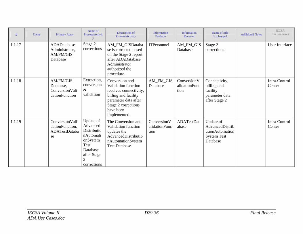
IECSA Volume II D29-36 Final Release ADA Use Cases.doc
# Event Primary Actor Name of
Process/Activity
Description of Process/Activity
Information Producer
Information Receiver
Name of Info Exchanged Additional Notes
IECSA Environments
1.1.17 ADADatabase Administrator, AM/FM/GIS Database
Stage 2 corrections
AM_FM_GISDatabase is corrected based on the Stage 2 report after ADADatabase Administrator authorized the procedure.
ITPersonnel AM_FM_GISDatabase
Stage 2 corrections
User Interface
1.1.18 AM/FM/GIS Database, ConversionValidationFunction
Extraction, conversion & validation
Conversion and Validation function receives connectivity, billing and facility parameter data after Stage 2 corrections have been implemented.
AM_FM_GISDatabase
ConversionValidationFunction
Connectivity, billing and facility parameter data after Stage 2
Intra-Control Center
1.1.19 ConversionValidationFunction, ADATestDatabase
Update of AdvancedDistributionAutomationSystem Test Database after Stage 2 corrections
The Conversion and Validation function updates the AdvancedDistributionAutomationSystem Test Database.
ConversionValidationFunction
ADATestDatabase
Update of AdvancedDistributionAutomationSystem Test Database
Intra-Control Center
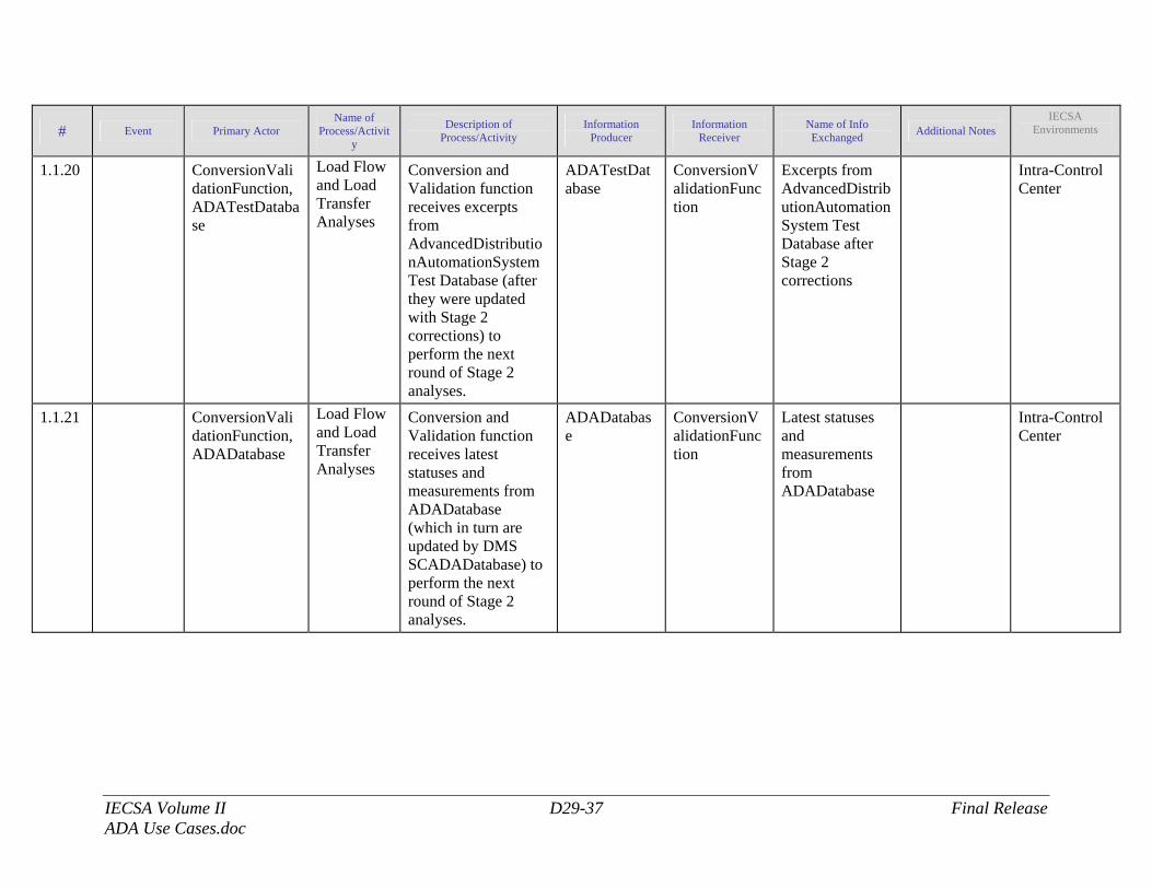
IECSA Volume II D29-37 Final Release ADA Use Cases.doc
# Event Primary Actor Name of
Process/Activity
Description of Process/Activity
Information Producer
Information Receiver
Name of Info Exchanged Additional Notes
IECSA Environments
1.1.20 ConversionValidationFunction, ADATestDatabase
Load Flow and Load Transfer Analyses
Conversion and Validation function receives excerpts from AdvancedDistributionAutomationSystem Test Database (after they were updated with Stage 2 corrections) to perform the next round of Stage 2 analyses.
ADATestDatabase
ConversionValidationFunction
Excerpts from AdvancedDistributionAutomationSystem Test Database after Stage 2 corrections
Intra-Control Center
1.1.21 ConversionValidationFunction, ADADatabase
Load Flow and Load Transfer Analyses
Conversion and Validation function receives latest statuses and measurements from ADADatabase (which in turn are updated by DMS SCADADatabase) to perform the next round of Stage 2 analyses.
ADADatabase
ConversionValidationFunction
Latest statuses and measurements from ADADatabase
Intra-Control Center
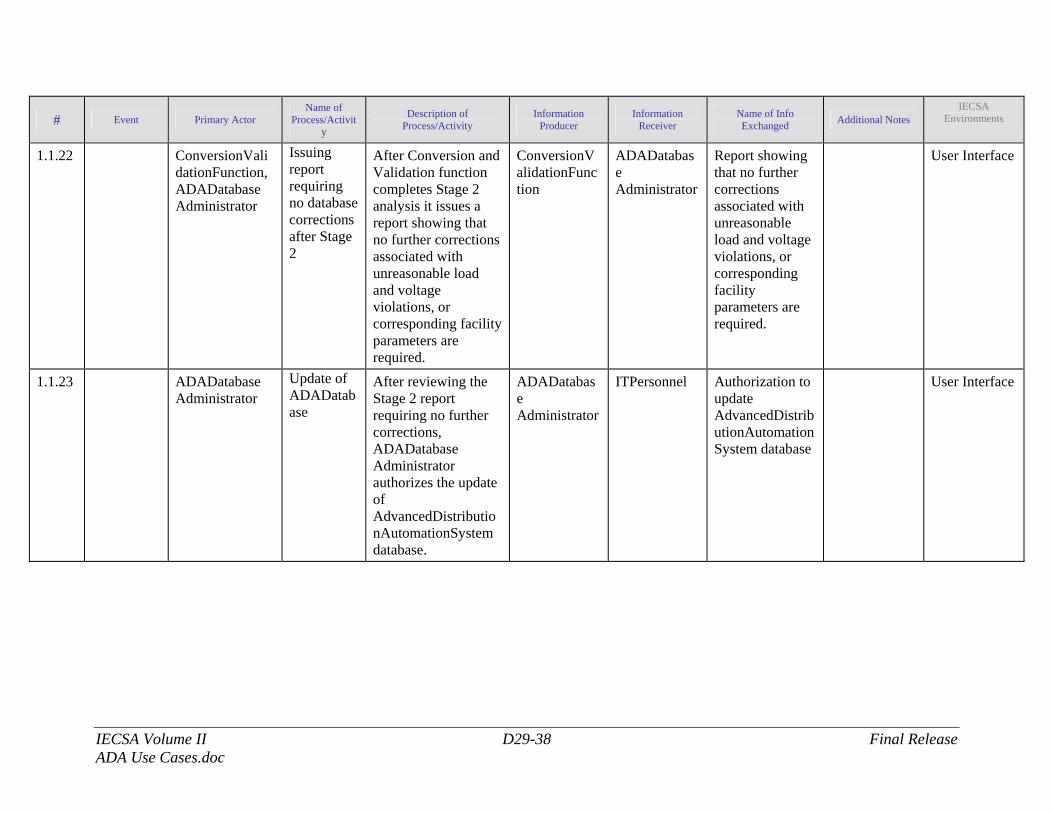
IECSA Volume II D29-38 Final Release ADA Use Cases.doc
# Event Primary Actor Name of
Process/Activity
Description of Process/Activity
Information Producer
Information Receiver
Name of Info Exchanged Additional Notes
IECSA Environments
1.1.22 ConversionValidationFunction, ADADatabase Administrator
Issuing report requiring no database corrections after Stage 2
After Conversion and Validation function completes Stage 2 analysis it issues a report showing that no further corrections associated with unreasonable load and voltage violations, or corresponding facility parameters are required.
ConversionValidationFunction
ADADatabase Administrator
Report showing that no further corrections associated with unreasonable load and voltage violations, or corresponding facility parameters are required.
User Interface
1.1.23 ADADatabase Administrator
Update of ADADatabase
After reviewing the Stage 2 report requiring no further corrections, ADADatabase Administrator authorizes the update of AdvancedDistributionAutomationSystem database.
ADADatabase Administrator
ITPersonnel Authorization to update AdvancedDistributionAutomationSystem database
User Interface
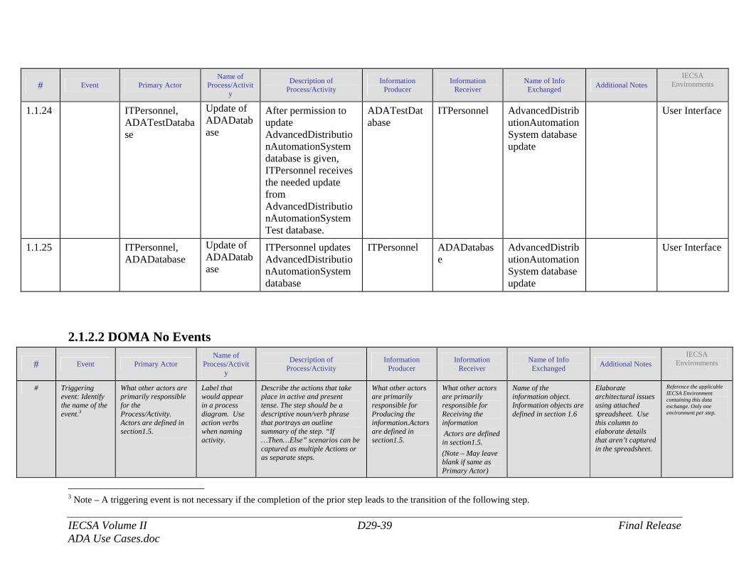
IECSA Volume II D29-39 Final Release ADA Use Cases.doc
# Event Primary Actor Name of
Process/Activity
Description of Process/Activity
Information Producer
Information Receiver
Name of Info Exchanged Additional Notes
IECSA Environments
1.1.24 ITPersonnel, ADATestDatabase
Update of ADADatabase
After permission to update AdvancedDistributionAutomationSystem database is given, ITPersonnel receives the needed update from AdvancedDistributionAutomationSystem Test database.
ADATestDatabase
ITPersonnel AdvancedDistributionAutomationSystem database update
User Interface
1.1.25 ITPersonnel, ADADatabase
Update of ADADatabase
ITPersonnel updates AdvancedDistributionAutomationSystem database
ITPersonnel ADADatabase
AdvancedDistributionAutomationSystem database update
User Interface
2.1.2.2 DOMA No Events
# Event Primary Actor Name of
Process/Activity
Description of Process/Activity
Information Producer
Information Receiver
Name of Info Exchanged Additional Notes
IECSA Environments
# Triggering event: Identify the name of the event.3
What other actors are primarily responsible for the Process/Activity. Actors are defined in section1.5.
Label that would appear in a process diagram. Use action verbs when naming activity.
Describe the actions that take place in active and present tense. The step should be a descriptive noun/verb phrase that portrays an outline summary of the step. “If …Then…Else” scenarios can be captured as multiple Actions or as separate steps.
What other actors are primarily responsible for Producing the information.Actors are defined in section1.5.
What other actors are primarily responsible for Receiving the information Actors are defined in section1.5. (Note – May leave blank if same as Primary Actor)
Name of the information object. Information objects are defined in section 1.6
Elaborate architectural issues using attached spreadsheet. Use this column to elaborate details that aren’t captured in the spreadsheet.
Reference the applicable IECSA Environment containing this data exchange. Only one environment per step.
3 Note – A triggering event is not necessary if the completion of the prior step leads to the transition of the following step.
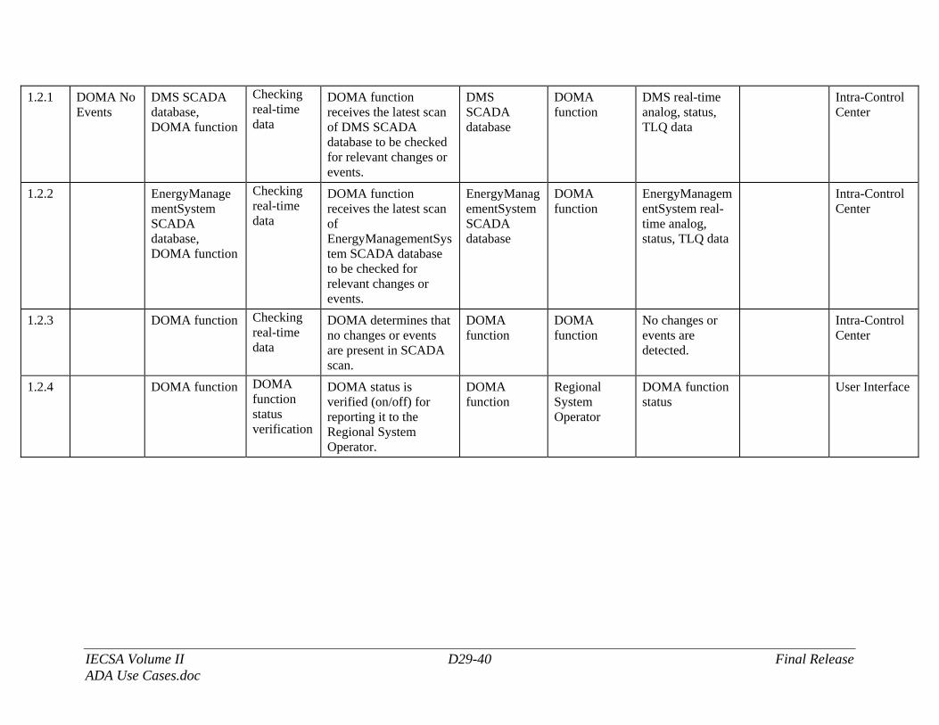
IECSA Volume II D29-40 Final Release ADA Use Cases.doc
1.2.1 DOMA No Events
DMS SCADA database, DOMA function
Checking real-time data
DOMA function receives the latest scan of DMS SCADA database to be checked for relevant changes or events.
DMS SCADA database
DOMA function
DMS real-time analog, status, TLQ data
Intra-Control Center
1.2.2 EnergyManagementSystem SCADA database, DOMA function
Checking real-time data
DOMA function receives the latest scan of EnergyManagementSystem SCADA database to be checked for relevant changes or events.
EnergyManagementSystem SCADA database
DOMA function
EnergyManagementSystem real-time analog, status, TLQ data
Intra-Control Center
1.2.3 DOMA function Checking real-time data
DOMA determines that no changes or events are present in SCADA scan.
DOMA function
DOMA function
No changes or events are detected.
Intra-Control Center
1.2.4 DOMA function DOMA function status verification
DOMA status is verified (on/off) for reporting it to the Regional System Operator.
DOMA function
Regional System Operator
DOMA function status
User Interface
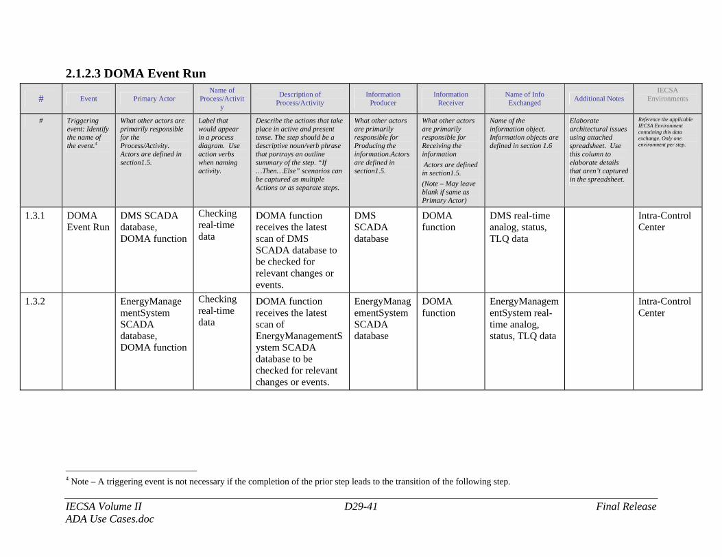
IECSA Volume II D29-41 Final Release ADA Use Cases.doc
2.1.2.3 DOMA Event Run
# Event Primary Actor Name of
Process/Activity
Description of Process/Activity
Information Producer
Information Receiver
Name of Info Exchanged Additional Notes
IECSA Environments
# Triggering event: Identify the name of the event.4
What other actors are primarily responsible for the Process/Activity. Actors are defined in section1.5.
Label that would appear in a process diagram. Use action verbs when naming activity.
Describe the actions that take place in active and present tense. The step should be a descriptive noun/verb phrase that portrays an outline summary of the step. “If …Then…Else” scenarios can be captured as multiple Actions or as separate steps.
What other actors are primarily responsible for Producing the information.Actors are defined in section1.5.
What other actors are primarily responsible for Receiving the information Actors are defined in section1.5. (Note – May leave blank if same as Primary Actor)
Name of the information object. Information objects are defined in section 1.6
Elaborate architectural issues using attached spreadsheet. Use this column to elaborate details that aren’t captured in the spreadsheet.
Reference the applicable IECSA Environment containing this data exchange. Only one environment per step.
1.3.1 DOMA Event Run
DMS SCADA database, DOMA function
Checking real-time data
DOMA function receives the latest scan of DMS SCADA database to be checked for relevant changes or events.
DMS SCADA database
DOMA function
DMS real-time analog, status, TLQ data
Intra-Control Center
1.3.2 EnergyManagementSystem SCADA database, DOMA function
Checking real-time data
DOMA function receives the latest scan of EnergyManagementSystem SCADA database to be checked for relevant changes or events.
EnergyManagementSystem SCADA database
DOMA function
EnergyManagementSystem real-time analog, status, TLQ data
Intra-Control Center
4 Note – A triggering event is not necessary if the completion of the prior step leads to the transition of the following step.
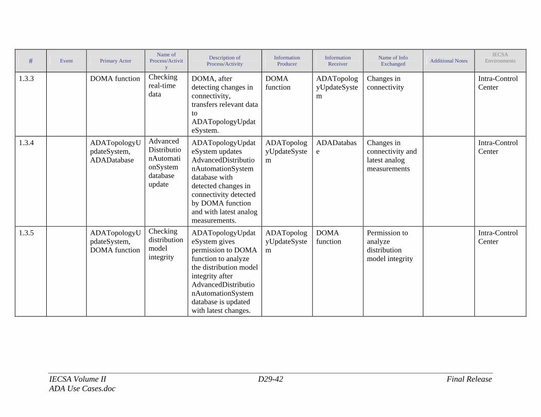
IECSA Volume II D29-42 Final Release ADA Use Cases.doc
# Event Primary Actor Name of
Process/Activity
Description of Process/Activity
Information Producer
Information Receiver
Name of Info Exchanged Additional Notes
IECSA Environments
1.3.3 DOMA function Checking real-time data
DOMA, after detecting changes in connectivity, transfers relevant data to ADATopologyUpdateSystem.
DOMA function
ADATopologyUpdateSystem
Changes in connectivity
Intra-Control Center
1.3.4 ADATopologyUpdateSystem, ADADatabase
AdvancedDistributionAutomationSystem database update
ADATopologyUpdateSystem updates AdvancedDistributionAutomationSystem database with detected changes in connectivity detected by DOMA function and with latest analog measurements.
ADATopologyUpdateSystem
ADADatabase
Changes in connectivity and latest analog measurements
Intra-Control Center
1.3.5 ADATopologyUpdateSystem, DOMA function
Checking distribution model integrity
ADATopologyUpdateSystem gives permission to DOMA function to analyze the distribution model integrity after AdvancedDistributionAutomationSystem database is updated with latest changes.
ADATopologyUpdateSystem
DOMA function
Permission to analyze distribution model integrity
Intra-Control Center
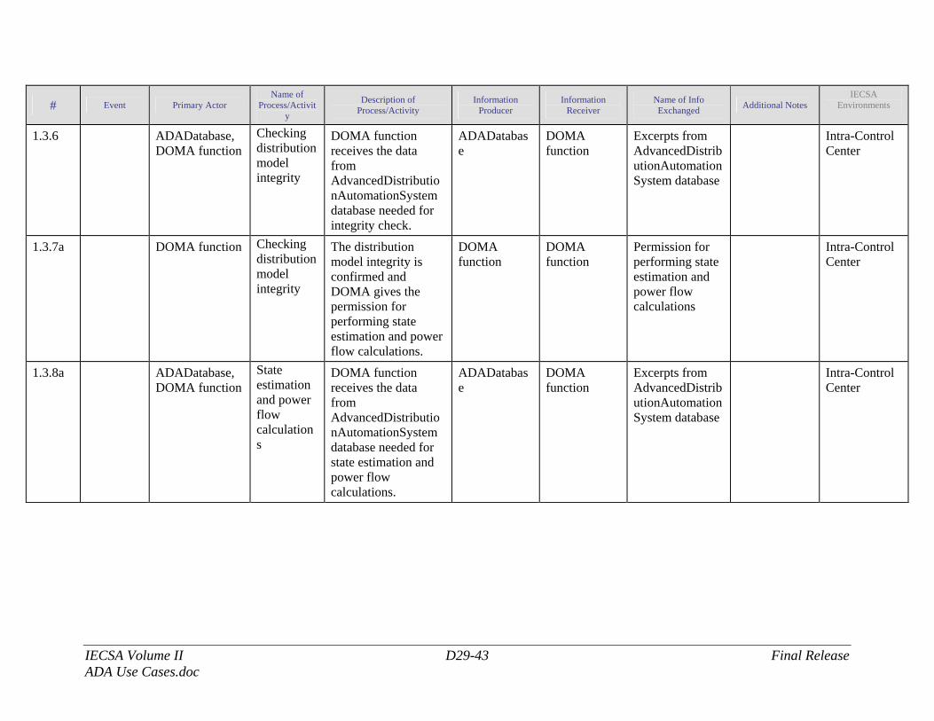
IECSA Volume II D29-43 Final Release ADA Use Cases.doc
# Event Primary Actor Name of
Process/Activity
Description of Process/Activity
Information Producer
Information Receiver
Name of Info Exchanged Additional Notes
IECSA Environments
1.3.6 ADADatabase, DOMA function
Checking distribution model integrity
DOMA function receives the data from AdvancedDistributionAutomationSystem database needed for integrity check.
ADADatabase
DOMA function
Excerpts from AdvancedDistributionAutomationSystem database
Intra-Control Center
1.3.7a DOMA function Checking distribution model integrity
The distribution model integrity is confirmed and DOMA gives the permission for performing state estimation and power flow calculations.
DOMA function
DOMA function
Permission for performing state estimation and power flow calculations
Intra-Control Center
1.3.8a ADADatabase, DOMA function
State estimation and power flow calculations
DOMA function receives the data from AdvancedDistributionAutomationSystem database needed for state estimation and power flow calculations.
ADADatabase
DOMA function
Excerpts from AdvancedDistributionAutomationSystem database
Intra-Control Center
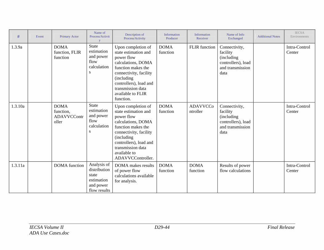
IECSA Volume II D29-44 Final Release ADA Use Cases.doc
# Event Primary Actor Name of
Process/Activity
Description of Process/Activity
Information Producer
Information Receiver
Name of Info Exchanged Additional Notes
IECSA Environments
1.3.9a DOMA function, FLIR function
State estimation and power flow calculations
Upon completion of state estimation and power flow calculations, DOMA function makes the connectivity, facility (including controllers), load and transmission data available to FLIR function.
DOMA function
FLIR function
Connectivity, facility (including controllers), load and transmission data
Intra-Control Center
1.3.10a DOMA function, ADAVVCController
State estimation and power flow calculations
Upon completion of state estimation and power flow calculations, DOMA function makes the connectivity, facility (including controllers), load and transmission data available to ADAVVCController.
DOMA function
ADAVVCController
Connectivity, facility (including controllers), load and transmission data
Intra-Control Center
1.3.11a DOMA function Analysis of distribution state estimation and power flow results
DOMA makes results of power flow calculations available for analysis.
DOMA function
DOMA function
Results of power flow calculations
Intra-Control Center
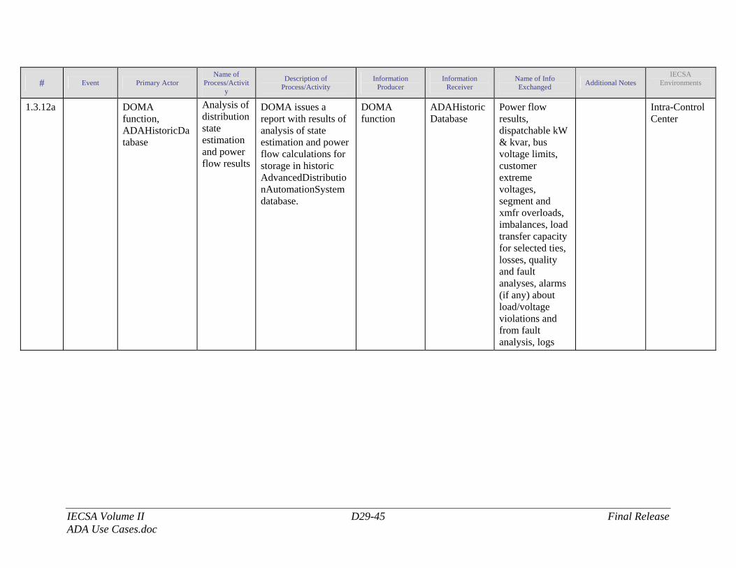
IECSA Volume II D29-45 Final Release ADA Use Cases.doc
# Event Primary Actor Name of
Process/Activity
Description of Process/Activity
Information Producer
Information Receiver
Name of Info Exchanged Additional Notes
IECSA Environments
1.3.12a DOMA function, ADAHistoricDatabase
Analysis of distribution state estimation and power flow results
DOMA issues a report with results of analysis of state estimation and power flow calculations for storage in historic AdvancedDistributionAutomationSystem database.
DOMA function
ADAHistoricDatabase
Power flow results, dispatchable kW & kvar, bus voltage limits, customer extreme voltages, segment and xmfr overloads, imbalances, load transfer capacity for selected ties, losses, quality and fault analyses, alarms (if any) about load/voltage violations and from fault analysis, logs
Intra-Control Center
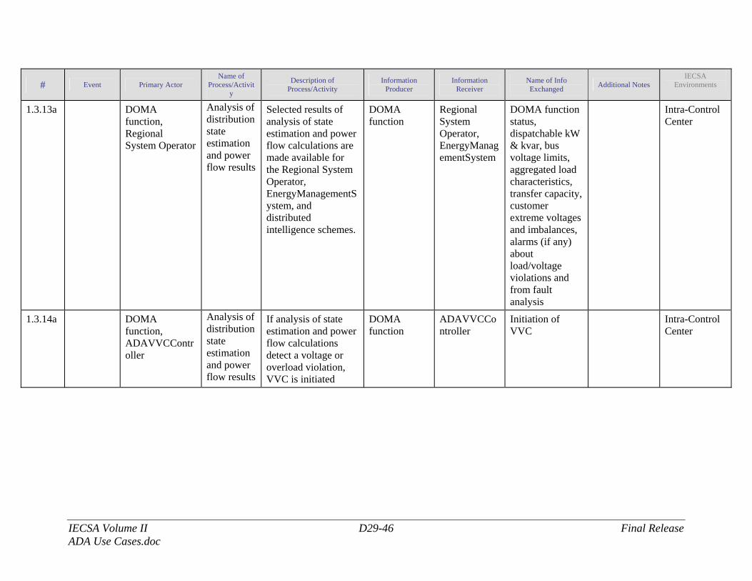
IECSA Volume II D29-46 Final Release ADA Use Cases.doc
# Event Primary Actor Name of
Process/Activity
Description of Process/Activity
Information Producer
Information Receiver
Name of Info Exchanged Additional Notes
IECSA Environments
1.3.13a DOMA function, Regional System Operator
Analysis of distribution state estimation and power flow results
Selected results of analysis of state estimation and power flow calculations are made available for the Regional System Operator, EnergyManagementSystem, and distributed intelligence schemes.
DOMA function
Regional System Operator, EnergyManagementSystem
DOMA function status, dispatchable kW & kvar, bus voltage limits, aggregated load characteristics, transfer capacity, customer extreme voltages and imbalances, alarms (if any) about load/voltage violations and from fault analysis
Intra-Control Center
1.3.14a DOMA function, ADAVVCController
Analysis of distribution state estimation and power flow results
If analysis of state estimation and power flow calculations detect a voltage or overload violation, VVC is initiated
DOMA function
ADAVVCController
Initiation of VVC
Intra-Control Center
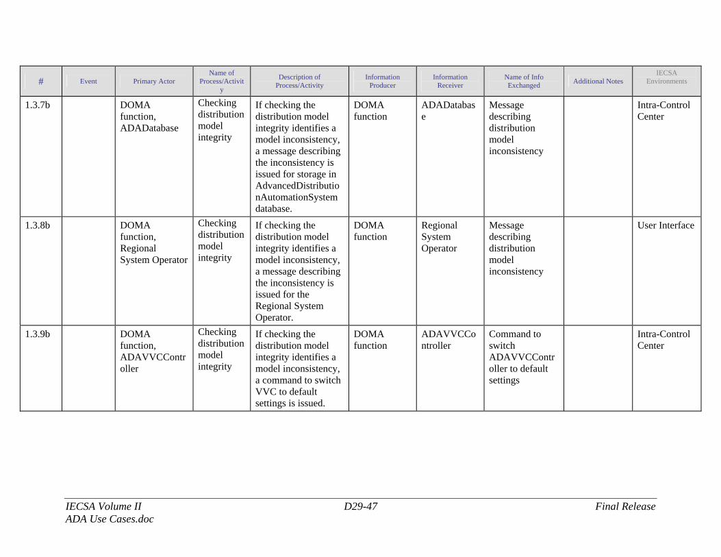
IECSA Volume II D29-47 Final Release ADA Use Cases.doc
# Event Primary Actor Name of
Process/Activity
Description of Process/Activity
Information Producer
Information Receiver
Name of Info Exchanged Additional Notes
IECSA Environments
1.3.7b DOMA function, ADADatabase
Checking distribution model integrity
If checking the distribution model integrity identifies a model inconsistency, a message describing the inconsistency is issued for storage in AdvancedDistributionAutomationSystem database.
DOMA function
ADADatabase
Message describing distribution model inconsistency
Intra-Control Center
1.3.8b DOMA function, Regional System Operator
Checking distribution model integrity
If checking the distribution model integrity identifies a model inconsistency, a message describing the inconsistency is issued for the Regional System Operator.
DOMA function
Regional System Operator
Message describing distribution model inconsistency
User Interface
1.3.9b DOMA function, ADAVVCController
Checking distribution model integrity
If checking the distribution model integrity identifies a model inconsistency, a command to switch VVC to default settings is issued.
DOMA function
ADAVVCController
Command to switch ADAVVCController to default settings
Intra-Control Center
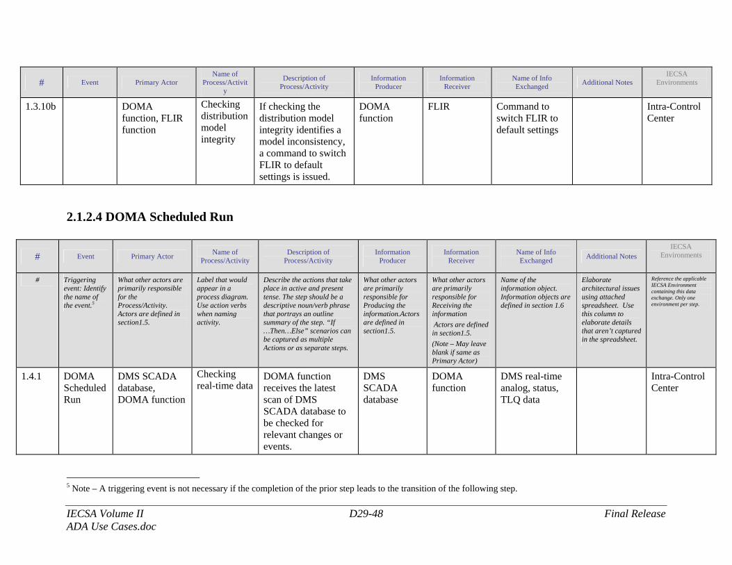
IECSA Volume II D29-48 Final Release ADA Use Cases.doc
# Event Primary Actor Name of
Process/Activity
Description of Process/Activity
Information Producer
Information Receiver
Name of Info Exchanged Additional Notes
IECSA Environments
1.3.10b DOMA function, FLIR function
Checking distribution model integrity
If checking the distribution model integrity identifies a model inconsistency, a command to switch FLIR to default settings is issued.
DOMA function
FLIR Command to switch FLIR to default settings
Intra-Control Center
2.1.2.4 DOMA Scheduled Run
# Event Primary Actor Name of Process/Activity
Description of Process/Activity
Information Producer
Information Receiver
Name of Info Exchanged Additional Notes
IECSA Environments
# Triggering event: Identify the name of the event.5
What other actors are primarily responsible for the Process/Activity. Actors are defined in section1.5.
Label that would appear in a process diagram. Use action verbs when naming activity.
Describe the actions that take place in active and present tense. The step should be a descriptive noun/verb phrase that portrays an outline summary of the step. “If …Then…Else” scenarios can be captured as multiple Actions or as separate steps.
What other actors are primarily responsible for Producing the information.Actors are defined in section1.5.
What other actors are primarily responsible for Receiving the information Actors are defined in section1.5. (Note – May leave blank if same as Primary Actor)
Name of the information object. Information objects are defined in section 1.6
Elaborate architectural issues using attached spreadsheet. Use this column to elaborate details that aren’t captured in the spreadsheet.
Reference the applicable IECSA Environment containing this data exchange. Only one environment per step.
1.4.1 DOMA Scheduled Run
DMS SCADA database, DOMA function
Checking real-time data
DOMA function receives the latest scan of DMS SCADA database to be checked for relevant changes or events.
DMS SCADA database
DOMA function
DMS real-time analog, status, TLQ data
Intra-Control Center
5 Note – A triggering event is not necessary if the completion of the prior step leads to the transition of the following step.
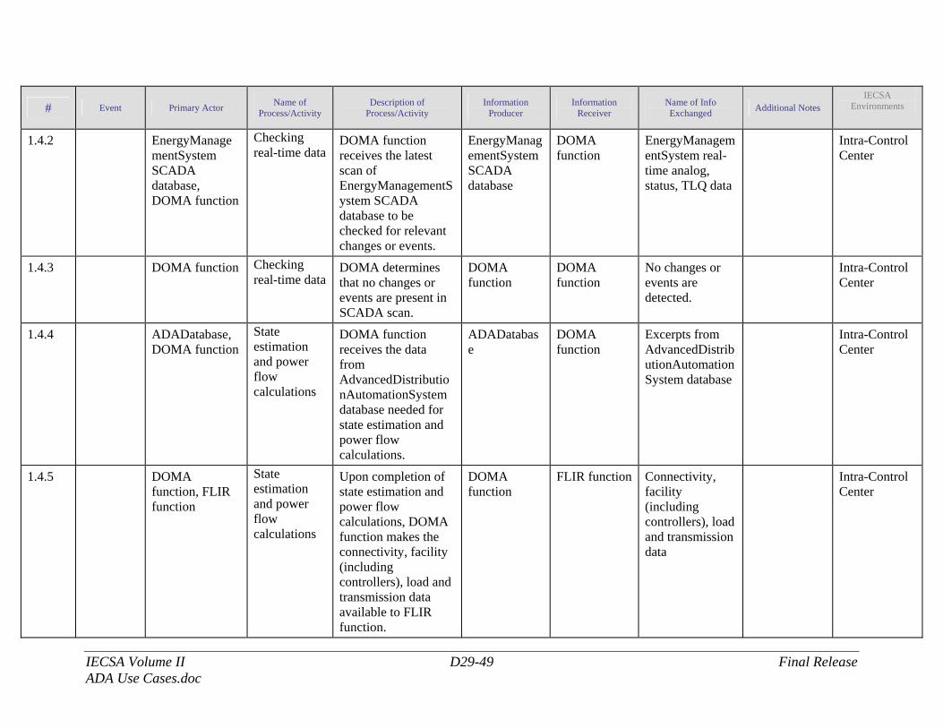
IECSA Volume II D29-49 Final Release ADA Use Cases.doc
# Event Primary Actor Name of Process/Activity
Description of Process/Activity
Information Producer
Information Receiver
Name of Info Exchanged Additional Notes
IECSA Environments
1.4.2 EnergyManagementSystem SCADA database, DOMA function
Checking real-time data
DOMA function receives the latest scan of EnergyManagementSystem SCADA database to be checked for relevant changes or events.
EnergyManagementSystem SCADA database
DOMA function
EnergyManagementSystem real-time analog, status, TLQ data
Intra-Control Center
1.4.3 DOMA function Checking real-time data
DOMA determines that no changes or events are present in SCADA scan.
DOMA function
DOMA function
No changes or events are detected.
Intra-Control Center
1.4.4 ADADatabase, DOMA function
State estimation and power flow calculations
DOMA function receives the data from AdvancedDistributionAutomationSystem database needed for state estimation and power flow calculations.
ADADatabase
DOMA function
Excerpts from AdvancedDistributionAutomationSystem database
Intra-Control Center
1.4.5 DOMA function, FLIR function
State estimation and power flow calculations
Upon completion of state estimation and power flow calculations, DOMA function makes the connectivity, facility (including controllers), load and transmission data available to FLIR function.
DOMA function
FLIR function
Connectivity, facility (including controllers), load and transmission data
Intra-Control Center
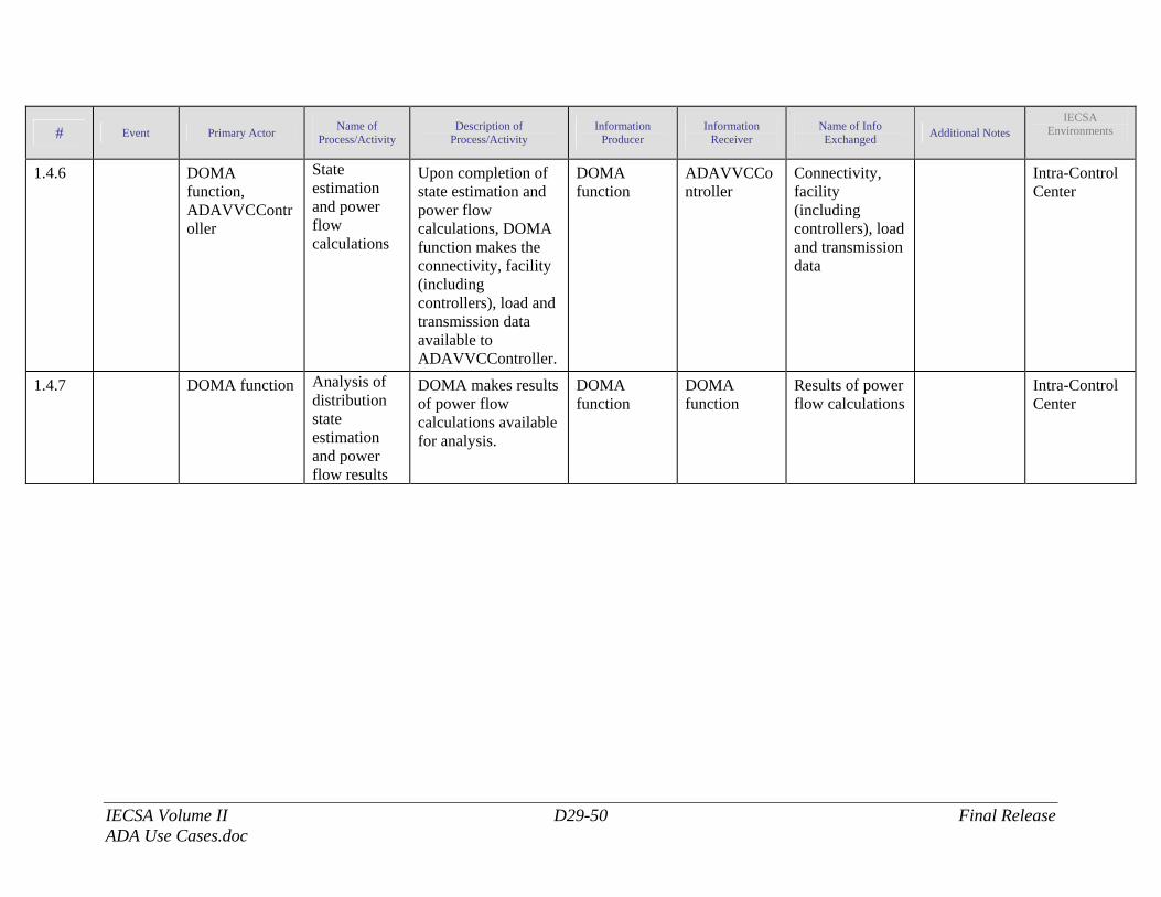
IECSA Volume II D29-50 Final Release ADA Use Cases.doc
# Event Primary Actor Name of Process/Activity
Description of Process/Activity
Information Producer
Information Receiver
Name of Info Exchanged Additional Notes
IECSA Environments
1.4.6 DOMA function, ADAVVCController
State estimation and power flow calculations
Upon completion of state estimation and power flow calculations, DOMA function makes the connectivity, facility (including controllers), load and transmission data available to ADAVVCController.
DOMA function
ADAVVCController
Connectivity, facility (including controllers), load and transmission data
Intra-Control Center
1.4.7 DOMA function Analysis of distribution state estimation and power flow results
DOMA makes results of power flow calculations available for analysis.
DOMA function
DOMA function
Results of power flow calculations
Intra-Control Center
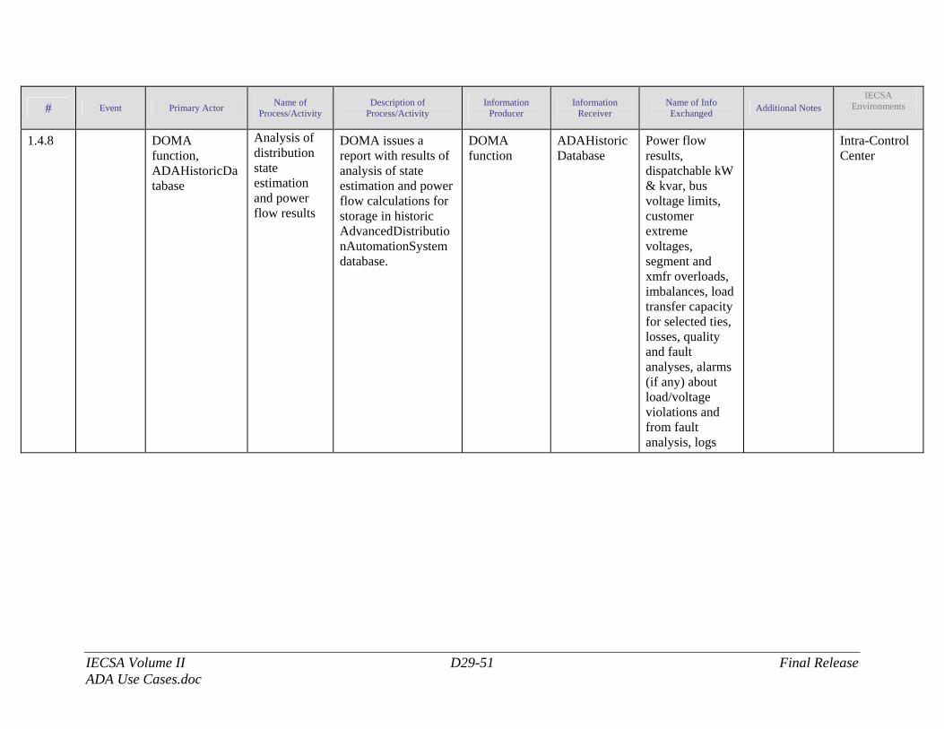
IECSA Volume II D29-51 Final Release ADA Use Cases.doc
# Event Primary Actor Name of Process/Activity
Description of Process/Activity
Information Producer
Information Receiver
Name of Info Exchanged Additional Notes
IECSA Environments
1.4.8 DOMA function, ADAHistoricDatabase
Analysis of distribution state estimation and power flow results
DOMA issues a report with results of analysis of state estimation and power flow calculations for storage in historic AdvancedDistributionAutomationSystem database.
DOMA function
ADAHistoricDatabase
Power flow results, dispatchable kW & kvar, bus voltage limits, customer extreme voltages, segment and xmfr overloads, imbalances, load transfer capacity for selected ties, losses, quality and fault analyses, alarms (if any) about load/voltage violations and from fault analysis, logs
Intra-Control Center
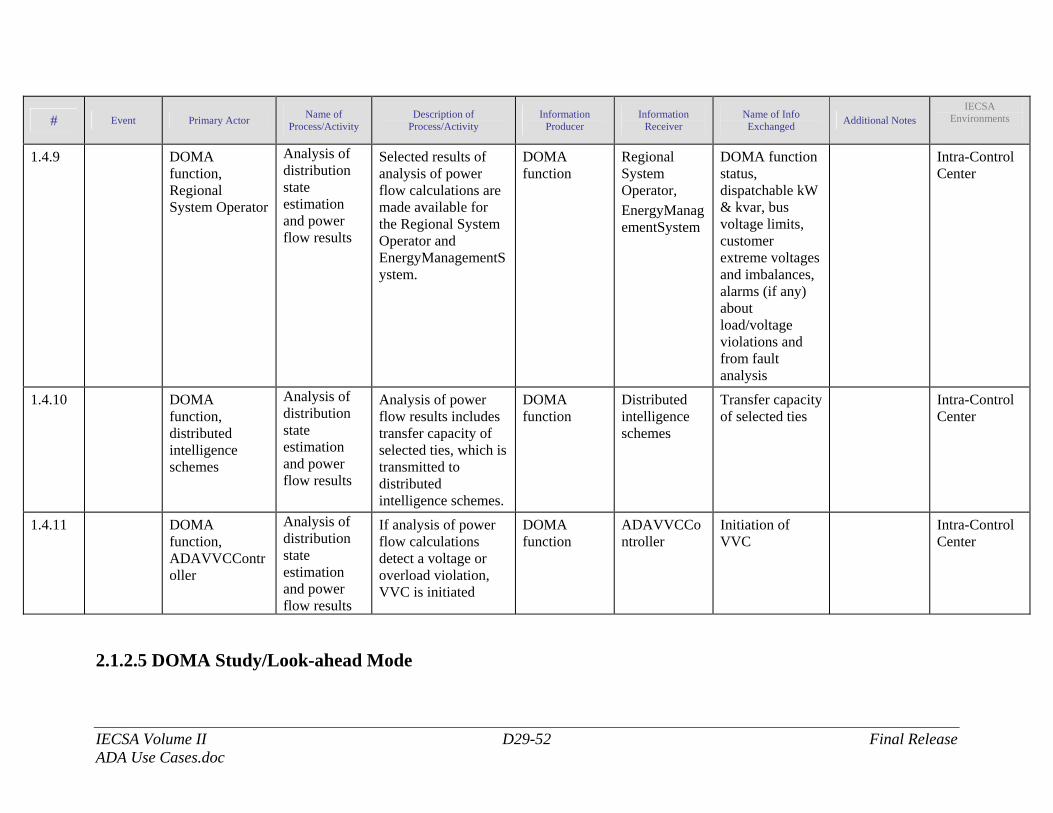
IECSA Volume II D29-52 Final Release ADA Use Cases.doc
# Event Primary Actor Name of Process/Activity
Description of Process/Activity
Information Producer
Information Receiver
Name of Info Exchanged Additional Notes
IECSA Environments
1.4.9 DOMA function, Regional System Operator
Analysis of distribution state estimation and power flow results
Selected results of analysis of power flow calculations are made available for the Regional System Operator and EnergyManagementSystem.
DOMA function
Regional System Operator, EnergyManagementSystem
DOMA function status, dispatchable kW & kvar, bus voltage limits, customer extreme voltages and imbalances, alarms (if any) about load/voltage violations and from fault analysis
Intra-Control Center
1.4.10 DOMA function, distributed intelligence schemes
Analysis of distribution state estimation and power flow results
Analysis of power flow results includes transfer capacity of selected ties, which is transmitted to distributed intelligence schemes.
DOMA function
Distributed intelligence schemes
Transfer capacity of selected ties
Intra-Control Center
1.4.11 DOMA function, ADAVVCController
Analysis of distribution state estimation and power flow results
If analysis of power flow calculations detect a voltage or overload violation, VVC is initiated
DOMA function
ADAVVCController
Initiation of VVC
Intra-Control Center
2.1.2.5 DOMA Study/Look-ahead Mode
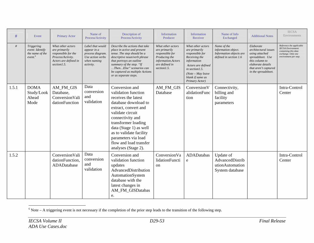
IECSA Volume II D29-53 Final Release ADA Use Cases.doc
# Event Primary Actor Name of Process/Activity
Description of Process/Activity
Information Producer
Information Receiver
Name of Info Exchanged Additional Notes
IECSA Environments
# Triggering event: Identify the name of the event.6
What other actors are primarily responsible for the Process/Activity. Actors are defined in section1.5.
Label that would appear in a process diagram. Use action verbs when naming activity.
Describe the actions that take place in active and present tense. The step should be a descriptive noun/verb phrase that portrays an outline summary of the step. “If …Then…Else” scenarios can be captured as multiple Actions or as separate steps.
What other actors are primarily responsible for Producing the information.Actors are defined in section1.5.
What other actors are primarily responsible for Receiving the information Actors are defined in section1.5. (Note – May leave blank if same as Primary Actor)
Name of the information object. Information objects are defined in section 1.6
Elaborate architectural issues using attached spreadsheet. Use this column to elaborate details that aren’t captured in the spreadsheet.
Reference the applicable IECSA Environment containing this data exchange. Only one environment per step.
1.5.1 DOMA Study/Look Ahead Mode
AM_FM_GISDatabase, ConversionValidationFunction
Data conversion and validation
Conversion and validation function receives the latest database download to extract, convert and validate circuit connectivity and transformer loading data (Stage 1) as well as to validate facility parameters via load flow and load transfer analyses (Stage 2).
AM_FM_GISDatabase
ConversionValidationFunction
Connectivity, billing and facility parameters
Intra-Control Center
1.5.2 ConversionValidationFunction, ADADatabase
Data conversion and validation
Conversion and validation function updates AdvancedDistributionAutomationSystem database with the latest changes in AM_FM_GISDatabase.
ConversionValidationFunction
ADADatabase
Update of AdvancedDistributionAutomationSystem database
Intra-Control Center
6 Note – A triggering event is not necessary if the completion of the prior step leads to the transition of the following step.
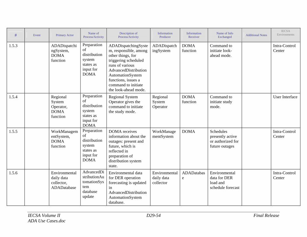
IECSA Volume II D29-54 Final Release ADA Use Cases.doc
# Event Primary Actor Name of Process/Activity
Description of Process/Activity
Information Producer
Information Receiver
Name of Info Exchanged Additional Notes
IECSA Environments
1.5.3 ADADispatchingSystem, DOMA function
Preparation of distribution system states as input for DOMA
ADADispatchingSystem, responsible, among other things, for triggering scheduled runs of various AdvancedDistributionAutomationSystem functions, issues a command to initiate the look-ahead mode.
ADADispatchingSystem
DOMA function
Command to initiate look-ahead mode.
Intra-Control Center
1.5.4 Regional System Operator, DOMA function
Preparation of distribution system states as input for DOMA
Regional System Operator gives the command to initiate the study mode.
Regional System Operator
DOMA function
Command to initiate study mode.
User Interface
1.5.5 WorkManagementSystem, DOMA function
Preparation of distribution system states as input for DOMA
DOMA receives information about the outages: present and future, which is reflected in preparation of distribution system state.
WorkManagementSystem
DOMA Schedules presently active or authorized for future outages
Intra-Control Center
1.5.6 Environmental daily data collector, ADADatabase
AdvancedDistributionAutomationSystem database update
Environmental data for DER operation forecasting is updated in AdvancedDistributionAutomationSystem database.
Environmental daily data collector
ADADatabase
Environmental data for DER load and schedule forecast
Intra-Control Center
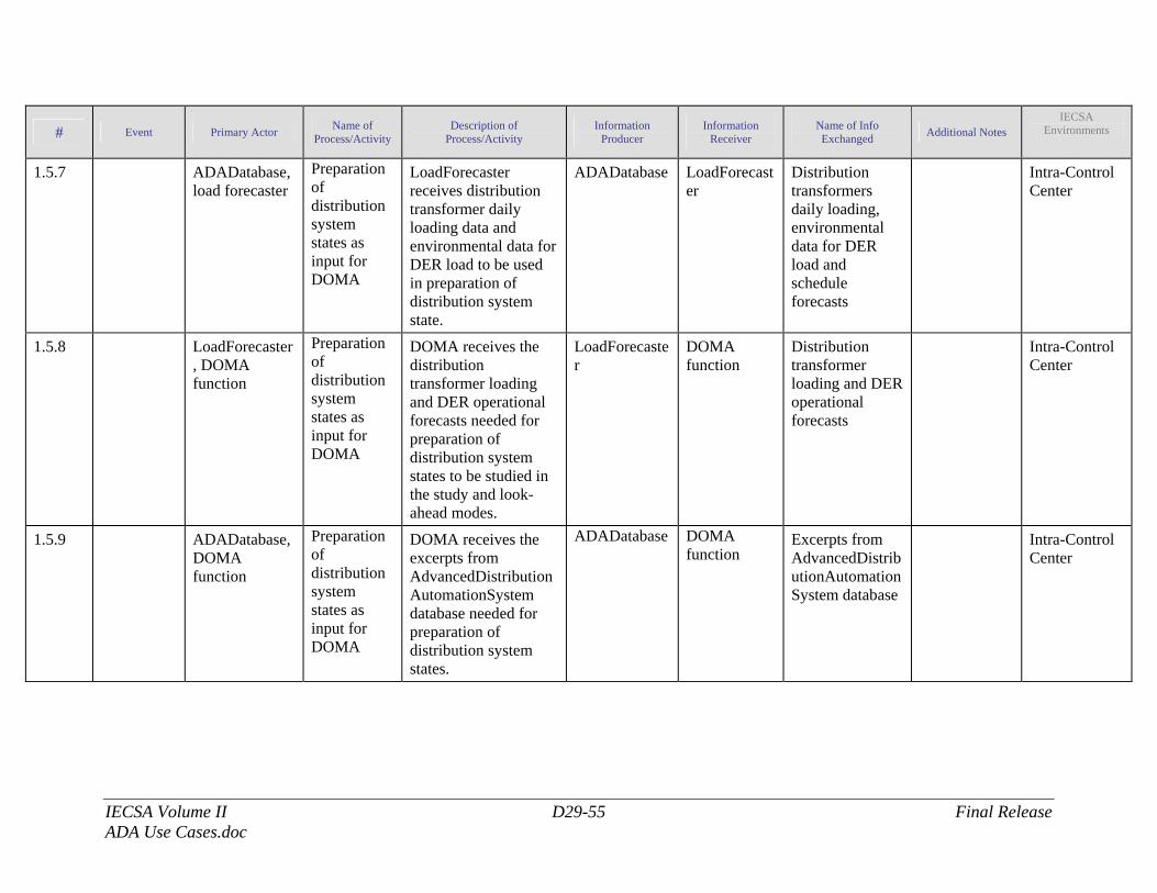
IECSA Volume II D29-55 Final Release ADA Use Cases.doc
# Event Primary Actor Name of Process/Activity
Description of Process/Activity
Information Producer
Information Receiver
Name of Info Exchanged Additional Notes
IECSA Environments
1.5.7 ADADatabase, load forecaster
Preparation of distribution system states as input for DOMA
LoadForecaster receives distribution transformer daily loading data and environmental data for DER load to be used in preparation of distribution system state.
ADADatabase LoadForecaster
Distribution transformers daily loading, environmental data for DER load and schedule forecasts
Intra-Control Center
1.5.8 LoadForecaster, DOMA function
Preparation of distribution system states as input for DOMA
DOMA receives the distribution transformer loading and DER operational forecasts needed for preparation of distribution system states to be studied in the study and look-ahead modes.
LoadForecaster
DOMA function
Distribution transformer loading and DER operational forecasts
Intra-Control Center
1.5.9 ADADatabase, DOMA function
Preparation of distribution system states as input for DOMA
DOMA receives the excerpts from AdvancedDistributionAutomationSystem database needed for preparation of distribution system states.
ADADatabase DOMA function
Excerpts from AdvancedDistributionAutomationSystem database
Intra-Control Center
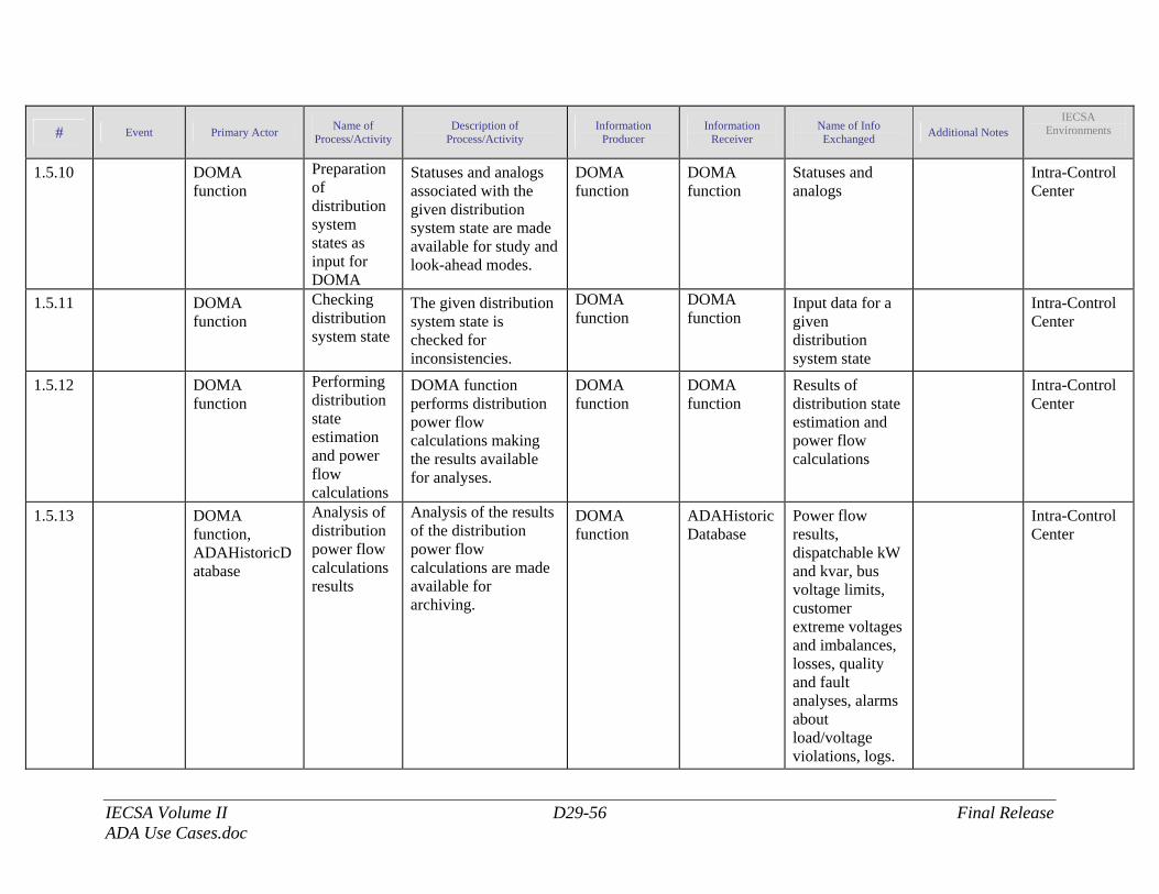
IECSA Volume II D29-56 Final Release ADA Use Cases.doc
# Event Primary Actor Name of Process/Activity
Description of Process/Activity
Information Producer
Information Receiver
Name of Info Exchanged Additional Notes
IECSA Environments
1.5.10 DOMA function
Preparation of distribution system states as input for DOMA
Statuses and analogs associated with the given distribution system state are made available for study and look-ahead modes.
DOMA function
DOMA function
Statuses and analogs
Intra-Control Center
1.5.11 DOMA function
Checking distribution system state
The given distribution system state is checked for inconsistencies.
DOMA function
DOMA function
Input data for a given distribution system state
Intra-Control Center
1.5.12 DOMA function
Performing distribution state estimation and power flow calculations
DOMA function performs distribution power flow calculations making the results available for analyses.
DOMA function
DOMA function
Results of distribution state estimation and power flow calculations
Intra-Control Center
1.5.13 DOMA function, ADAHistoricDatabase
Analysis of distribution power flow calculations results
Analysis of the results of the distribution power flow calculations are made available for archiving.
DOMA function
ADAHistoricDatabase
Power flow results, dispatchable kW and kvar, bus voltage limits, customer extreme voltages and imbalances, losses, quality and fault analyses, alarms about load/voltage violations, logs.
Intra-Control Center
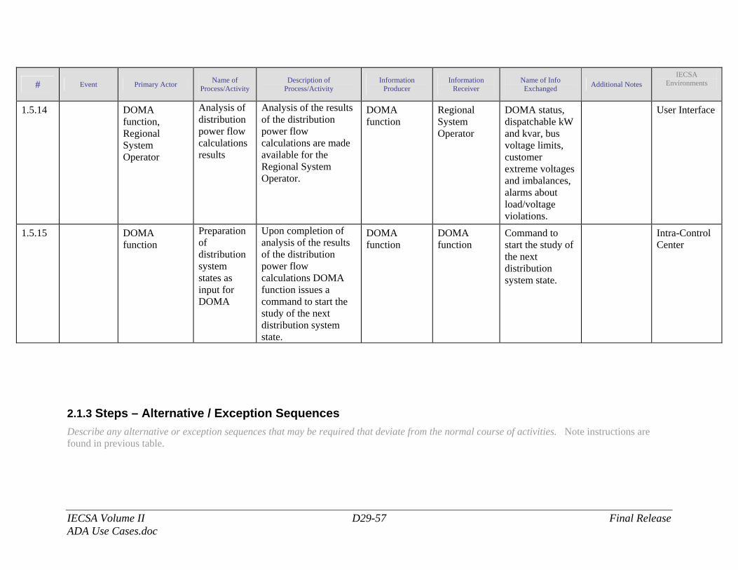
IECSA Volume II D29-57 Final Release ADA Use Cases.doc
# Event Primary Actor Name of Process/Activity
Description of Process/Activity
Information Producer
Information Receiver
Name of Info Exchanged Additional Notes
IECSA Environments
1.5.14 DOMA function, Regional System Operator
Analysis of distribution power flow calculations results
Analysis of the results of the distribution power flow calculations are made available for the Regional System Operator.
DOMA function
Regional System Operator
DOMA status, dispatchable kW and kvar, bus voltage limits, customer extreme voltages and imbalances, alarms about load/voltage violations.
User Interface
1.5.15 DOMA function
Preparation of distribution system states as input for DOMA
Upon completion of analysis of the results of the distribution power flow calculations DOMA function issues a command to start the study of the next distribution system state.
DOMA function
DOMA function
Command to start the study of the next distribution system state.
Intra-Control Center
2.1.3 Steps – Alternative / Exception Sequences Describe any alternative or exception sequences that may be required that deviate from the normal course of activities. Note instructions are found in previous table.
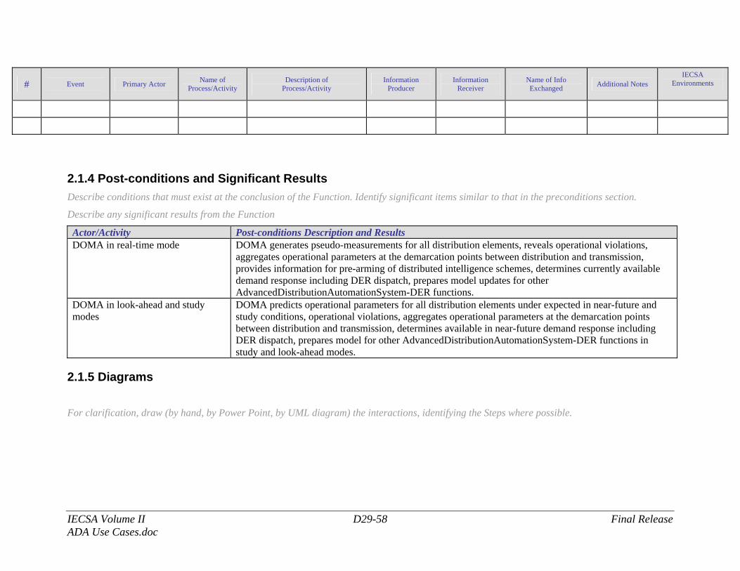
IECSA Volume II D29-58 Final Release ADA Use Cases.doc
# Event Primary Actor Name of Process/Activity
Description of Process/Activity
Information Producer
Information Receiver
Name of Info Exchanged Additional Notes
IECSA Environments
2.1.4 Post-conditions and Significant Results Describe conditions that must exist at the conclusion of the Function. Identify significant items similar to that in the preconditions section.
Describe any significant results from the Function
Actor/Activity Post-conditions Description and Results DOMA in real-time mode DOMA generates pseudo-measurements for all distribution elements, reveals operational violations,
aggregates operational parameters at the demarcation points between distribution and transmission, provides information for pre-arming of distributed intelligence schemes, determines currently available demand response including DER dispatch, prepares model updates for other AdvancedDistributionAutomationSystem-DER functions.
DOMA in look-ahead and study modes
DOMA predicts operational parameters for all distribution elements under expected in near-future and study conditions, operational violations, aggregates operational parameters at the demarcation points between distribution and transmission, determines available in near-future demand response including DER dispatch, prepares model for other AdvancedDistributionAutomationSystem-DER functions in study and look-ahead modes.
2.1.5 Diagrams
For clarification, draw (by hand, by Power Point, by UML diagram) the interactions, identifying the Steps where possible.
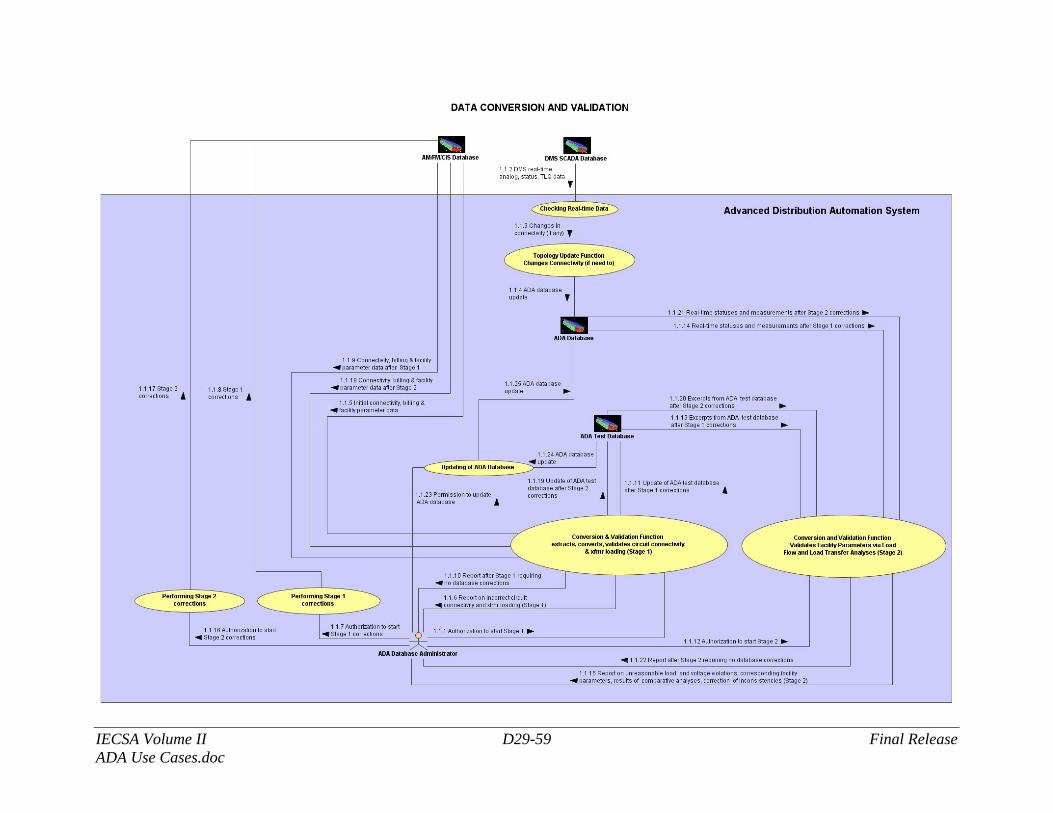
IECSA Volume II D29-59 Final Release ADA Use Cases.doc
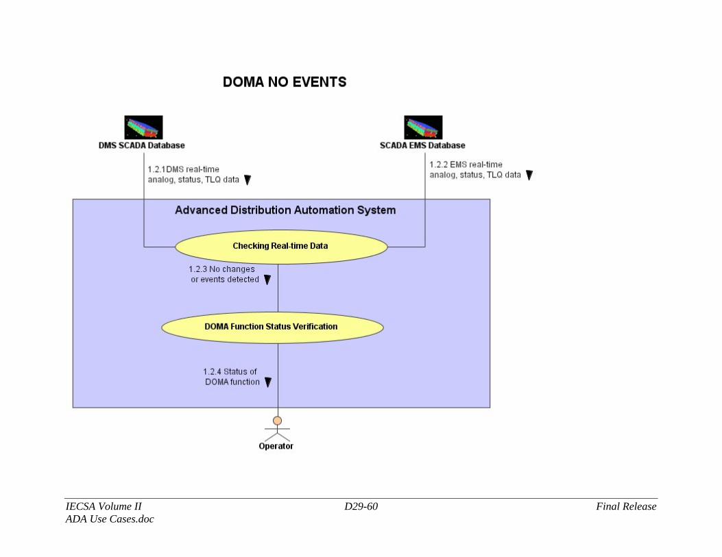
IECSA Volume II D29-60 Final Release ADA Use Cases.doc
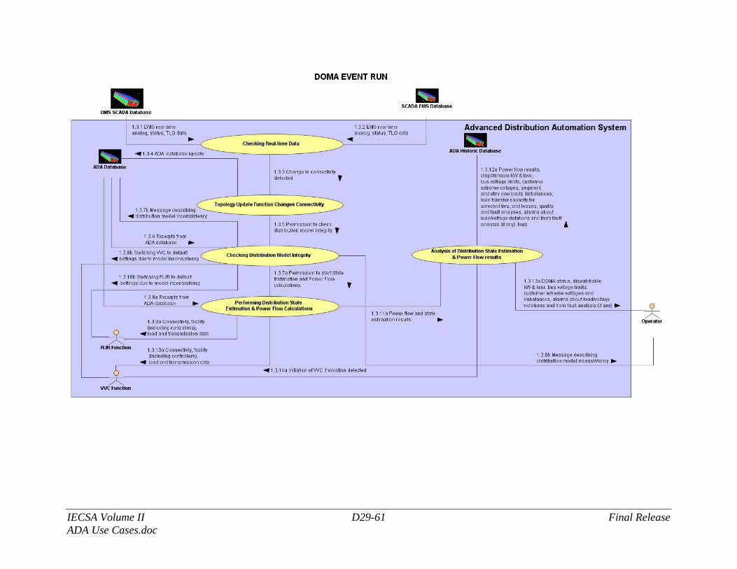
IECSA Volume II D29-61 Final Release ADA Use Cases.doc
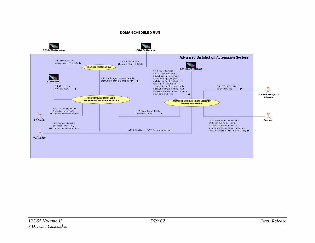
IECSA Volume II D29-62 Final Release ADA Use Cases.doc
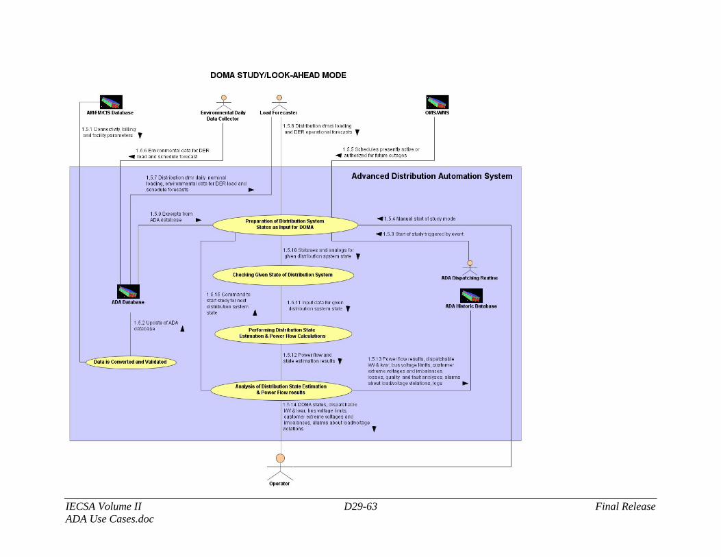
IECSA Volume II D29-63 Final Release ADA Use Cases.doc
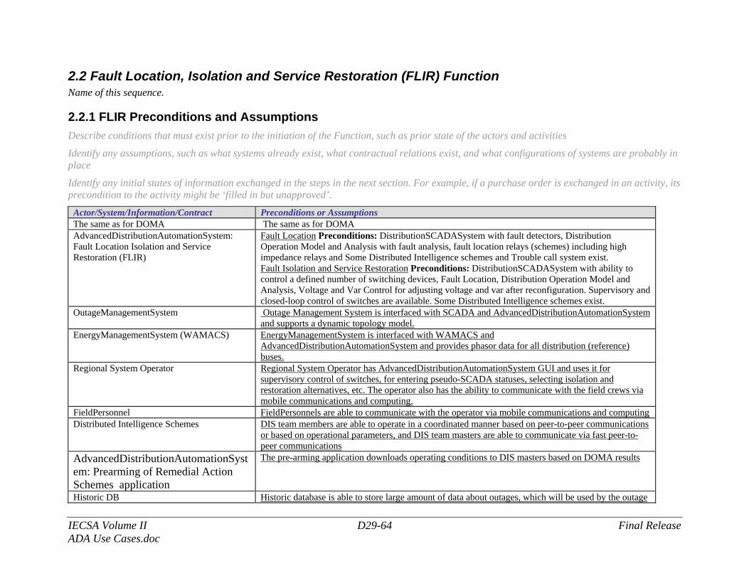
IECSA Volume II D29-64 Final Release ADA Use Cases.doc
2.2 Fault Location, Isolation and Service Restoration (FLIR) Function Name of this sequence.
2.2.1 FLIR Preconditions and Assumptions Describe conditions that must exist prior to the initiation of the Function, such as prior state of the actors and activities
Identify any assumptions, such as what systems already exist, what contractual relations exist, and what configurations of systems are probably in place
Identify any initial states of information exchanged in the steps in the next section. For example, if a purchase order is exchanged in an activity, its precondition to the activity might be ‘filled in but unapproved’.
Actor/System/Information/Contract Preconditions or Assumptions The same as for DOMA The same as for DOMA AdvancedDistributionAutomationSystem: Fault Location Isolation and Service Restoration (FLIR)
Fault Location Preconditions: DistributionSCADASystem with fault detectors, Distribution Operation Model and Analysis with fault analysis, fault location relays (schemes) including high impedance relays and Some Distributed Intelligence schemes and Trouble call system exist. Fault Isolation and Service Restoration Preconditions: DistributionSCADASystem with ability to control a defined number of switching devices, Fault Location, Distribution Operation Model and Analysis, Voltage and Var Control for adjusting voltage and var after reconfiguration. Supervisory and closed-loop control of switches are available. Some Distributed Intelligence schemes exist.
OutageManagementSystem Outage Management System is interfaced with SCADA and AdvancedDistributionAutomationSystem and supports a dynamic topology model.
EnergyManagementSystem (WAMACS) EnergyManagementSystem is interfaced with WAMACS and AdvancedDistributionAutomationSystem and provides phasor data for all distribution (reference) buses.
Regional System Operator Regional System Operator has AdvancedDistributionAutomationSystem GUI and uses it for supervisory control of switches, for entering pseudo-SCADA statuses, selecting isolation and restoration alternatives, etc. The operator also has the ability to communicate with the field crews via mobile communications and computing.
FieldPersonnel FieldPersonnels are able to communicate with the operator via mobile communications and computing Distributed Intelligence Schemes DIS team members are able to operate in a coordinated manner based on peer-to-peer communications
or based on operational parameters, and DIS team masters are able to communicate via fast peer-to-peer communications
AdvancedDistributionAutomationSystem: Prearming of Remedial Action Schemes application
The pre-arming application downloads operating conditions to DIS masters based on DOMA results
Historic DB Historic database is able to store large amount of data about outages, which will be used by the outage
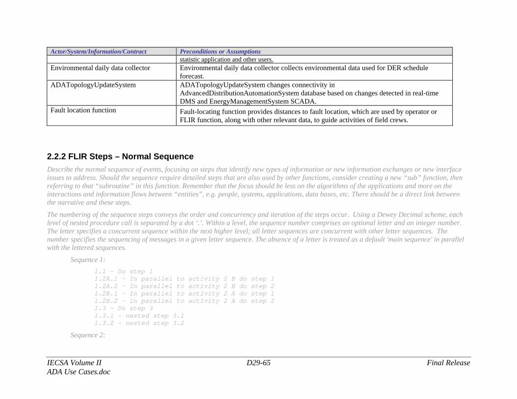
IECSA Volume II D29-65 Final Release ADA Use Cases.doc
Actor/System/Information/Contract Preconditions or Assumptions statistic application and other users.
Environmental daily data collector Environmental daily data collector collects environmental data used for DER schedule forecast.
ADATopologyUpdateSystem ADATopologyUpdateSystem changes connectivity in AdvancedDistributionAutomationSystem database based on changes detected in real-time DMS and EnergyManagementSystem SCADA.
Fault location function Fault-locating function provides distances to fault location, which are used by operator or FLIR function, along with other relevant data, to guide activities of field crews.
2.2.2 FLIR Steps – Normal Sequence Describe the normal sequence of events, focusing on steps that identify new types of information or new information exchanges or new interface issues to address. Should the sequence require detailed steps that are also used by other functions, consider creating a new “sub” function, then referring to that “subroutine” in this function. Remember that the focus should be less on the algorithms of the applications and more on the interactions and information flows between “entities”, e.g. people, systems, applications, data bases, etc. There should be a direct link between the narrative and these steps.
The numbering of the sequence steps conveys the order and concurrency and iteration of the steps occur. Using a Dewey Decimal scheme, each level of nested procedure call is separated by a dot ‘.’. Within a level, the sequence number comprises an optional letter and an integer number. The letter specifies a concurrent sequence within the next higher level; all letter sequences are concurrent with other letter sequences. The number specifies the sequencing of messages in a given letter sequence. The absence of a letter is treated as a default 'main sequence' in parallel with the lettered sequences.
Sequence 1: 1.1 - Do step 1 1.2A.1 - In parallel to activity 2 B do step 1
1.2A.2 - In parallel to activity 2 B do step 2 1.2B.1 - In parallel to activity 2 A do step 1 1.2B.2 - In parallel to activity 2 A do step 2 1.3 - Do step 3
1.3.1 - nested step 3.1 1.3.2 - nested step 3.2
Sequence 2:
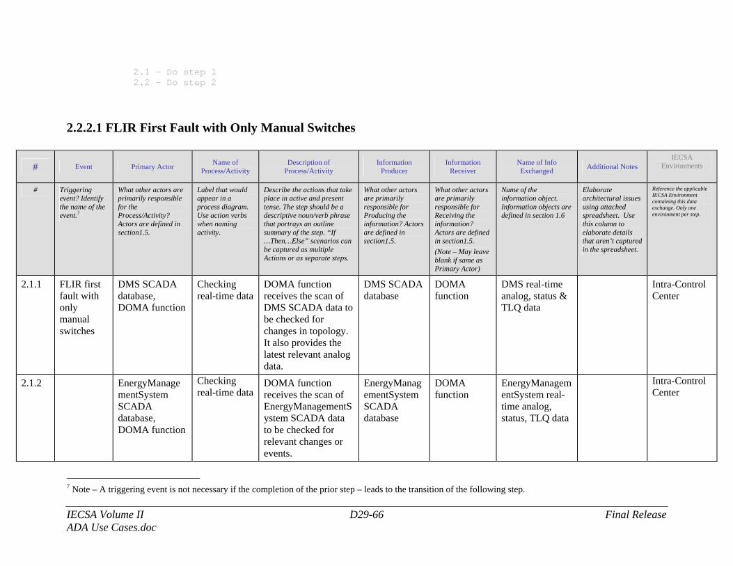
IECSA Volume II D29-66 Final Release ADA Use Cases.doc
2.1 - Do step 1 2.2 – Do step 2
2.2.2.1 FLIR First Fault with Only Manual Switches
# Event Primary Actor Name of Process/Activity
Description of Process/Activity
Information Producer
Information Receiver
Name of Info Exchanged Additional Notes
IECSA Environments
# Triggering event? Identify the name of the event.7
What other actors are primarily responsible for the Process/Activity? Actors are defined in section1.5.
Label that would appear in a process diagram. Use action verbs when naming activity.
Describe the actions that take place in active and present tense. The step should be a descriptive noun/verb phrase that portrays an outline summary of the step. “If …Then…Else” scenarios can be captured as multiple Actions or as separate steps.
What other actors are primarily responsible for Producing the information? Actors are defined in section1.5.
What other actors are primarily responsible for Receiving the information? Actors are defined in section1.5. (Note – May leave blank if same as Primary Actor)
Name of the information object. Information objects are defined in section 1.6
Elaborate architectural issues using attached spreadsheet. Use this column to elaborate details that aren’t captured in the spreadsheet.
Reference the applicable IECSA Environment containing this data exchange. Only one environment per step.
2.1.1 FLIR first fault with only manual switches
DMS SCADA database, DOMA function
Checking real-time data
DOMA function receives the scan of DMS SCADA data to be checked for changes in topology. It also provides the latest relevant analog data.
DMS SCADA database
DOMA function
DMS real-time analog, status & TLQ data
Intra-Control Center
2.1.2 EnergyManagementSystem SCADA database, DOMA function
Checking real-time data
DOMA function receives the scan of EnergyManagementSystem SCADA data to be checked for relevant changes or events.
EnergyManagementSystem SCADA database
DOMA function
EnergyManagementSystem real-time analog, status, TLQ data
Intra-Control Center
7 Note – A triggering event is not necessary if the completion of the prior step – leads to the transition of the following step.
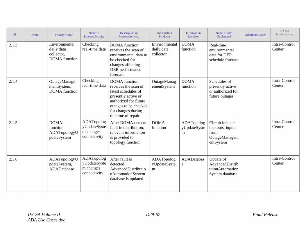
IECSA Volume II D29-67 Final Release ADA Use Cases.doc
# Event Primary Actor Name of Process/Activity
Description of Process/Activity
Information Producer
Information Receiver
Name of Info Exchanged Additional Notes
IECSA Environments
2.1.3 Environmental daily data collector, DOMA function
Checking real-time data
DOMA function receives the scan of environmental data to be checked for changes affecting DER performance forecast.
Environmental daily data collector
DOMA function
Real-time environmental data for DER schedule forecast
Intra-Control Center
2.1.4 OutageManagementSystem, DOMA function
Checking real-time data
DOMA function receives the scan of latest schedules of presently active or authorized for future outages to be checked for changes during the time of repair.
OutageManagementSystem
DOMA function
Schedules of presently active or authorized for future outages
Intra-Control Center
2.1.5 DOMA function, ADATopologyUpdateSystem
ADATopologyUpdateSystem changes connectivity
After DOMA detects fault in distribution, relevant information is provided to topology function.
DOMA function
ADATopologyUpdateSystem
Circuit breaker lockouts, inputs from OutageManagementSystem
Intra-Control Center
2.1.6 ADATopologyUpdateSystem, ADADatabase
ADATopologyUpdateSystem changes connectivity
After fault is detected, AdvancedDistributionAutomationSystem database is updated.
ADATopologyUpdateSystem
ADADatabase
Update of AdvancedDistributionAutomationSystem database
Intra-Control Center
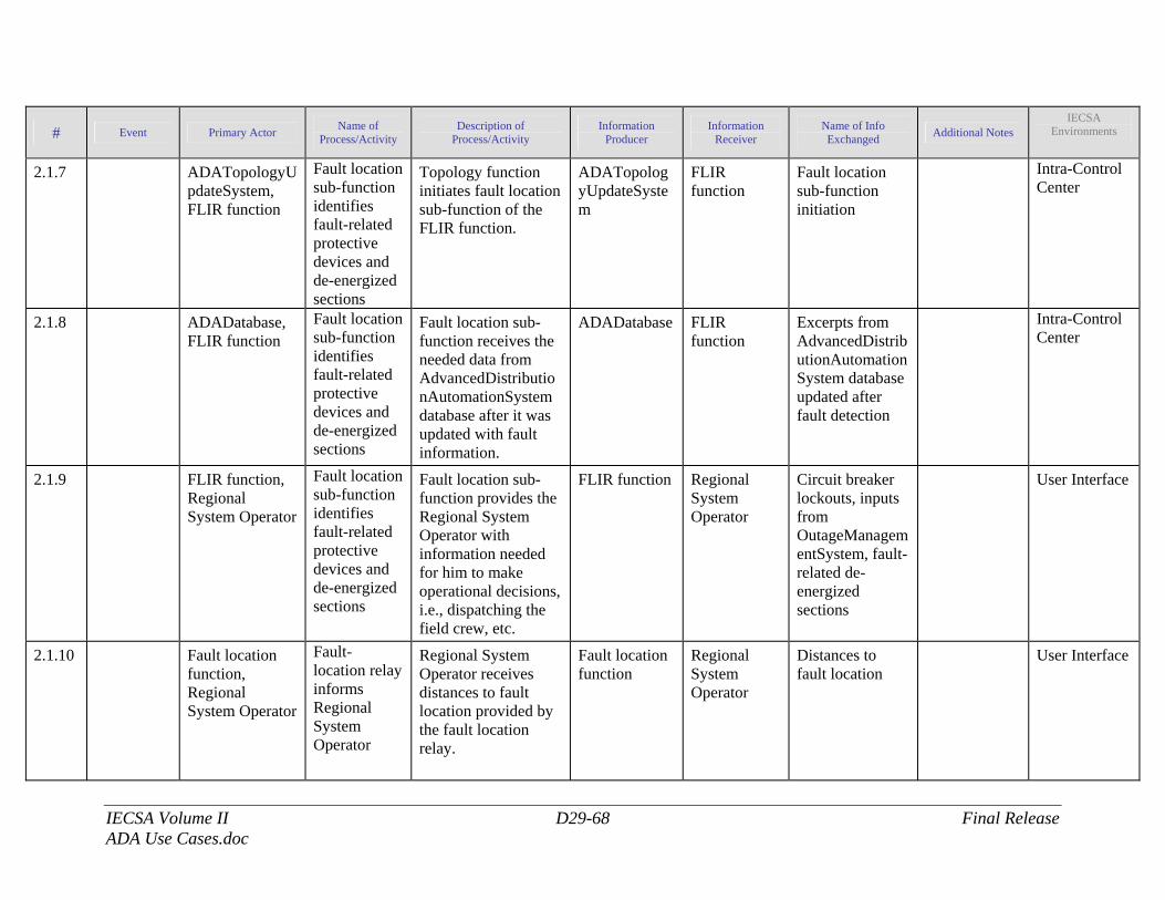
IECSA Volume II D29-68 Final Release ADA Use Cases.doc
# Event Primary Actor Name of Process/Activity
Description of Process/Activity
Information Producer
Information Receiver
Name of Info Exchanged Additional Notes
IECSA Environments
2.1.7 ADATopologyUpdateSystem, FLIR function
Fault location sub-function identifies fault-related protective devices and de-energized sections
Topology function initiates fault location sub-function of the FLIR function.
ADATopologyUpdateSystem
FLIR function
Fault location sub-function initiation
Intra-Control Center
2.1.8 ADADatabase, FLIR function
Fault location sub-function identifies fault-related protective devices and de-energized sections
Fault location sub-function receives the needed data from AdvancedDistributionAutomationSystem database after it was updated with fault information.
ADADatabase FLIR function
Excerpts from AdvancedDistributionAutomationSystem database updated after fault detection
Intra-Control Center
2.1.9 FLIR function, Regional System Operator
Fault location sub-function identifies fault-related protective devices and de-energized sections
Fault location sub-function provides the Regional System Operator with information needed for him to make operational decisions, i.e., dispatching the field crew, etc.
FLIR function Regional System Operator
Circuit breaker lockouts, inputs from OutageManagementSystem, fault-related de-energized sections
User Interface
2.1.10 Fault location function, Regional System Operator
Fault- location relay informs Regional System Operator
Regional System Operator receives distances to fault location provided by the fault location relay.
Fault location function
Regional System Operator
Distances to fault location
User Interface
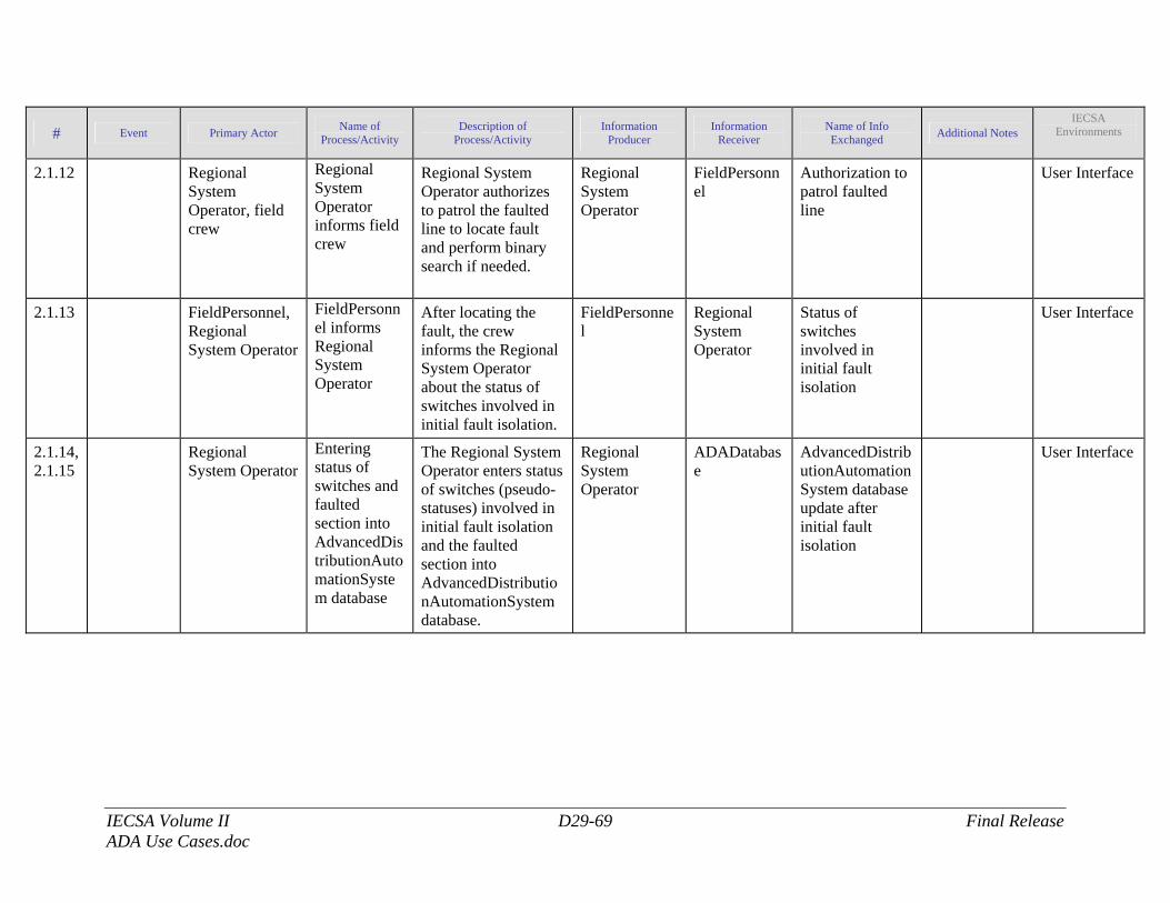
IECSA Volume II D29-69 Final Release ADA Use Cases.doc
# Event Primary Actor Name of Process/Activity
Description of Process/Activity
Information Producer
Information Receiver
Name of Info Exchanged Additional Notes
IECSA Environments
2.1.12 Regional System Operator, field crew
Regional System Operator informs field crew
Regional System Operator authorizes to patrol the faulted line to locate fault and perform binary search if needed.
Regional System Operator
FieldPersonnel
Authorization to patrol faulted line
User Interface
2.1.13 FieldPersonnel, Regional System Operator
FieldPersonnel informs Regional System Operator
After locating the fault, the crew informs the Regional System Operator about the status of switches involved in initial fault isolation.
FieldPersonnel
Regional System Operator
Status of switches involved in initial fault isolation
User Interface
2.1.14, 2.1.15
Regional System Operator
Entering status of switches and faulted section into AdvancedDistributionAutomationSystem database
The Regional System Operator enters status of switches (pseudo-statuses) involved in initial fault isolation and the faulted section into AdvancedDistributionAutomationSystem database.
Regional System Operator
ADADatabase
AdvancedDistributionAutomationSystem database update after initial fault isolation
User Interface
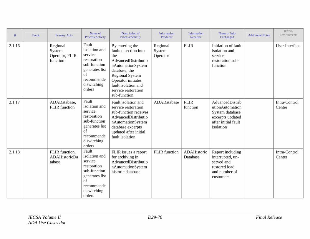
IECSA Volume II D29-70 Final Release ADA Use Cases.doc
# Event Primary Actor Name of Process/Activity
Description of Process/Activity
Information Producer
Information Receiver
Name of Info Exchanged Additional Notes
IECSA Environments
2.1.16 Regional System Operator, FLIR function
Fault isolation and service restoration sub-function generates list of recommended switching orders
By entering the faulted section into the AdvancedDistributionAutomationSystem database, the Regional System Operator initiates fault isolation and service restoration sub-function.
Regional System Operator
FLIR Initiation of fault isolation and service restoration sub-function
User Interface
2.1.17 ADADatabase, FLIR function
Fault isolation and service restoration sub-function generates list of recommended switching orders
Fault isolation and service restoration sub-function receives AdvancedDistributionAutomationSystem database excerpts updated after initial fault isolation.
ADADatabase FLIR function
AdvancedDistributionAutomationSystem database excerpts updated after initial fault isolation
Intra-Control Center
2.1.18 FLIR function, ADAHistoricDatabase
Fault isolation and service restoration sub-function generates list of recommended switching orders
FLIR issues a report for archiving in AdvancedDistributionAutomationSystem historic database
FLIR function ADAHistoricDatabase
Report including interrupted, un-served and restored load, and number of customers
Intra-Control Center
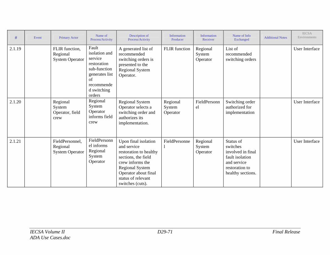
IECSA Volume II D29-71 Final Release ADA Use Cases.doc
# Event Primary Actor Name of Process/Activity
Description of Process/Activity
Information Producer
Information Receiver
Name of Info Exchanged Additional Notes
IECSA Environments
2.1.19 FLIR function, Regional System Operator
Fault isolation and service restoration sub-function generates list of recommended switching orders
A generated list of recommended switching orders is presented to the Regional System Operator.
FLIR function Regional System Operator
List of recommended switching orders
User Interface
2.1.20 Regional System Operator, field crew
Regional System Operator informs field crew
Regional System Operator selects a switching order and authorizes its implementation.
Regional System Operator
FieldPersonnel
Switching order authorized for implementation
User Interface
2.1.21 FieldPersonnel, Regional System Operator
FieldPersonnel informs Regional System Operator
Upon final isolation and service restoration to healthy sections, the field crew informs the Regional System Operator about final status of relevant switches (cuts).
FieldPersonnel
Regional System Operator
Status of switches involved in final fault isolation and service restoration to healthy sections.
User Interface
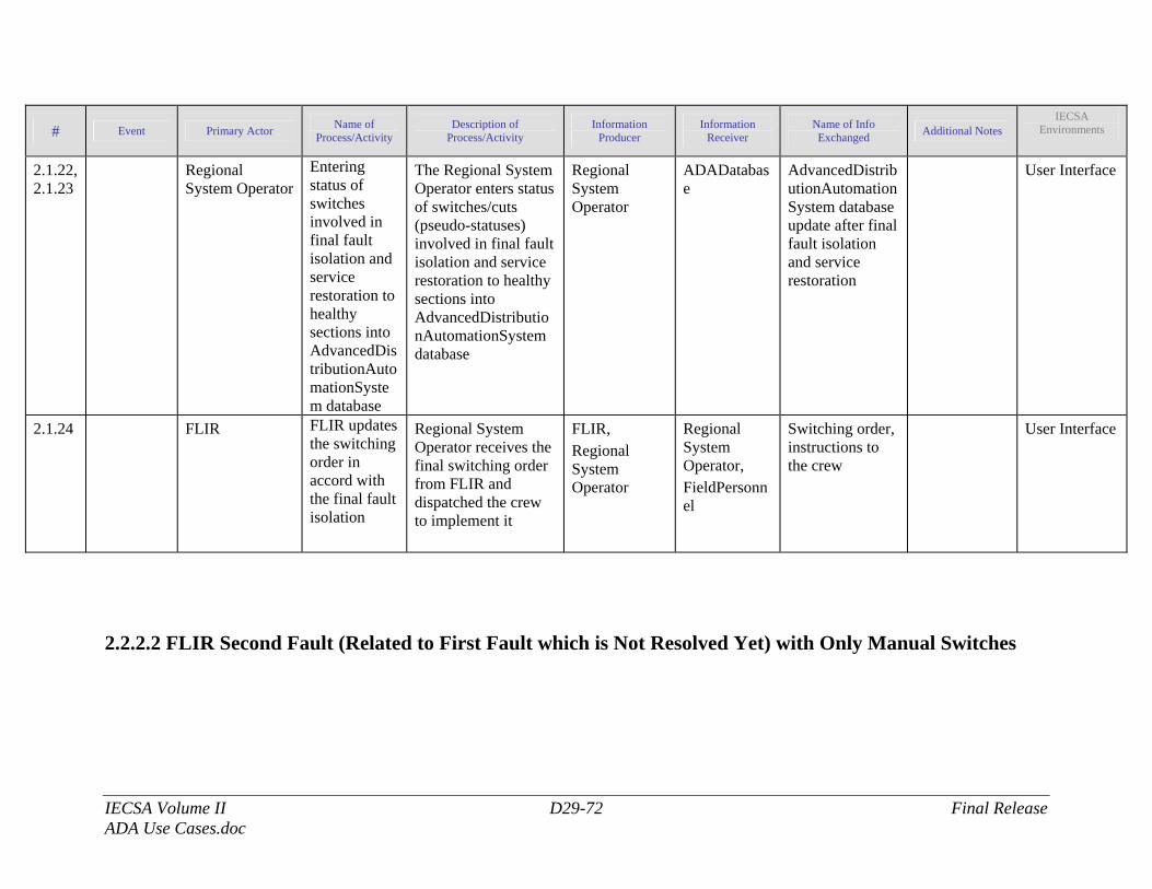
IECSA Volume II D29-72 Final Release ADA Use Cases.doc
# Event Primary Actor Name of Process/Activity
Description of Process/Activity
Information Producer
Information Receiver
Name of Info Exchanged Additional Notes
IECSA Environments
2.1.22, 2.1.23
Regional System Operator
Entering status of switches involved in final fault isolation and service restoration to healthy sections into AdvancedDistributionAutomationSystem database
The Regional System Operator enters status of switches/cuts (pseudo-statuses) involved in final fault isolation and service restoration to healthy sections into AdvancedDistributionAutomationSystem database
Regional System Operator
ADADatabase
AdvancedDistributionAutomationSystem database update after final fault isolation and service restoration
User Interface
2.1.24 FLIR FLIR updates the switching order in accord with the final fault isolation
Regional System Operator receives the final switching order from FLIR and dispatched the crew to implement it
FLIR, Regional System Operator
Regional System Operator, FieldPersonnel
Switching order, instructions to the crew
User Interface
2.2.2.2 FLIR Second Fault (Related to First Fault which is Not Resolved Yet) with Only Manual Switches
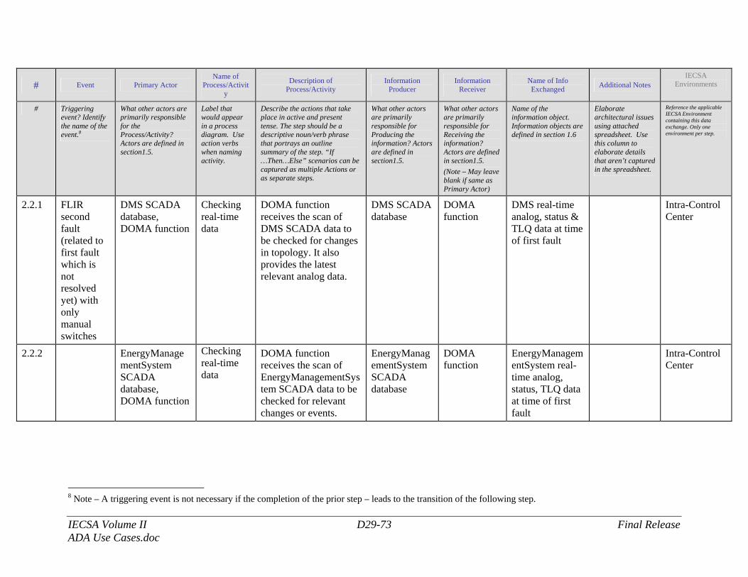
IECSA Volume II D29-73 Final Release ADA Use Cases.doc
# Event Primary Actor Name of
Process/Activity
Description of Process/Activity
Information Producer
Information Receiver
Name of Info Exchanged Additional Notes
IECSA Environments
# Triggering event? Identify the name of the event.8
What other actors are primarily responsible for the Process/Activity? Actors are defined in section1.5.
Label that would appear in a process diagram. Use action verbs when naming activity.
Describe the actions that take place in active and present tense. The step should be a descriptive noun/verb phrase that portrays an outline summary of the step. “If …Then…Else” scenarios can be captured as multiple Actions or as separate steps.
What other actors are primarily responsible for Producing the information? Actors are defined in section1.5.
What other actors are primarily responsible for Receiving the information? Actors are defined in section1.5. (Note – May leave blank if same as Primary Actor)
Name of the information object. Information objects are defined in section 1.6
Elaborate architectural issues using attached spreadsheet. Use this column to elaborate details that aren’t captured in the spreadsheet.
Reference the applicable IECSA Environment containing this data exchange. Only one environment per step.
2.2.1 FLIR second fault (related to first fault which is not resolved yet) with only manual switches
DMS SCADA database, DOMA function
Checking real-time data
DOMA function receives the scan of DMS SCADA data to be checked for changes in topology. It also provides the latest relevant analog data.
DMS SCADA database
DOMA function
DMS real-time analog, status & TLQ data at time of first fault
Intra-Control Center
2.2.2 EnergyManagementSystem SCADA database, DOMA function
Checking real-time data
DOMA function receives the scan of EnergyManagementSystem SCADA data to be checked for relevant changes or events.
EnergyManagementSystem SCADA database
DOMA function
EnergyManagementSystem real-time analog, status, TLQ data at time of first fault
Intra-Control Center
8 Note – A triggering event is not necessary if the completion of the prior step – leads to the transition of the following step.

IECSA Volume II D29-74 Final Release ADA Use Cases.doc
# Event Primary Actor Name of
Process/Activity
Description of Process/Activity
Information Producer
Information Receiver
Name of Info Exchanged Additional Notes
IECSA Environments
2.2.3 Environmental daily data collector, DOMA function
Checking real-time data
DOMA function receives the scan of environmental data to be checked for changes affecting DER performance forecast.
Environmental daily data collector
DOMA function
Real-time environmental data for DER schedule forecast at time of first fault
Intra-Control Center
2.2.4 OutageManagementSystem, DOMA function
Checking real-time data
DOMA function receives the scan of latest schedules of presently active or authorized for future outages to be checked for changes.
OutageManagementSystem
DOMA function
Schedules of presently active or authorized for future outages at time of first fault
Intra-Control Center
2.2.5 DOMA function, ADATopologyUpdateSystem
ADATopologyUpdateSystem changes connectivity
After DOMA detects first fault in distribution, relevant information is provided to topology function.
DOMA function
ADATopologyUpdateSystem
First fault: circuit breaker lockouts, inputs from OutageManagementSystem
Intra-Control Center
2.2.6 ADATopologyUpdateSystem, ADADatabase
ADATopologyUpdateSystem changes connectivity
After first fault is detected, AdvancedDistributionAutomationSystem database is updated.
ADATopologyUpdateSystem
ADADatabase
Update of AdvancedDistributionAutomationSystem database after first fault detection
Intra-Control Center

IECSA Volume II D29-75 Final Release ADA Use Cases.doc
# Event Primary Actor Name of
Process/Activity
Description of Process/Activity
Information Producer
Information Receiver
Name of Info Exchanged Additional Notes
IECSA Environments
2.2.7 ADATopologyUpdateSystem, FLIR function
Fault location sub-function identifies fault-related protective devices and de-energized sections
After the first fault is detected, topology function initiates fault location sub-function of the FLIR function.
ADATopologyUpdateSystem
FLIR function
Fault location sub-function initiation after first fault
Intra-Control Center
2.2.8 ADADatabase, FLIR function
Fault location sub-function identifies fault-related protective devices and de-energized sections
Fault location sub-function receives the needed data from AdvancedDistributionAutomationSystem database after it was updated with the first fault information.
ADADatabase FLIR function
Excerpts from AdvancedDistributionAutomationSystem database updated after first fault detection
Intra-Control Center
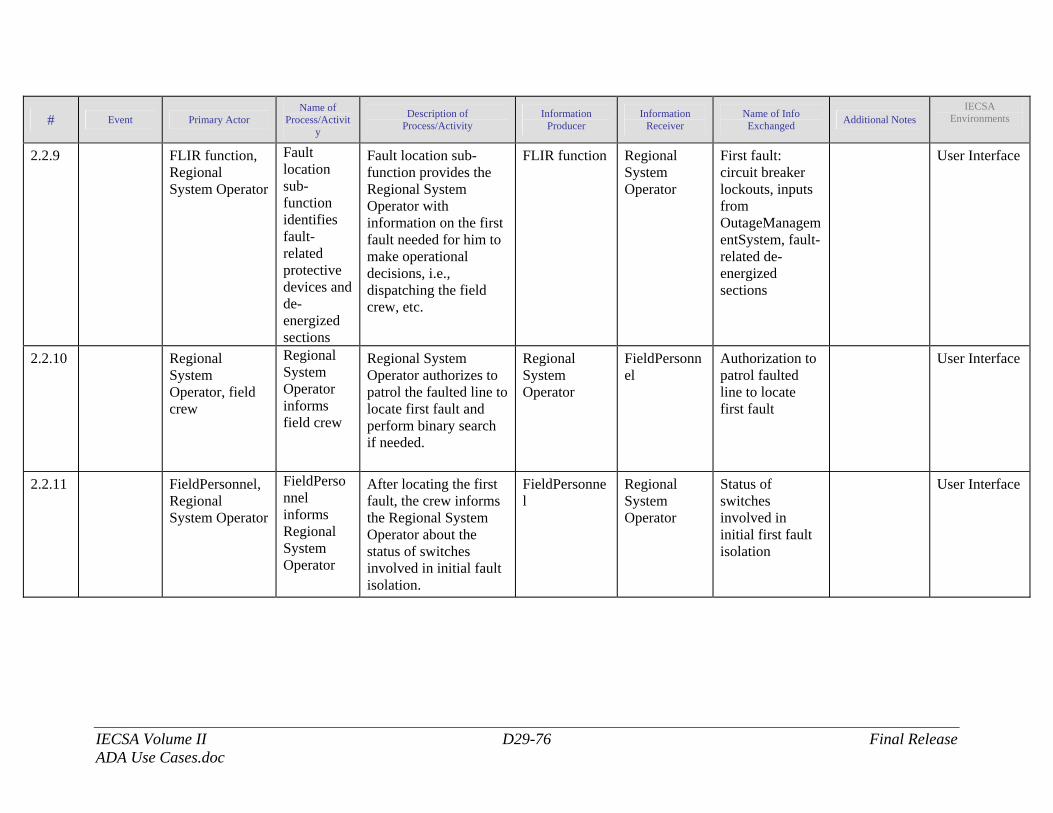
IECSA Volume II D29-76 Final Release ADA Use Cases.doc
# Event Primary Actor Name of
Process/Activity
Description of Process/Activity
Information Producer
Information Receiver
Name of Info Exchanged Additional Notes
IECSA Environments
2.2.9 FLIR function, Regional System Operator
Fault location sub-function identifies fault-related protective devices and de-energized sections
Fault location sub-function provides the Regional System Operator with information on the first fault needed for him to make operational decisions, i.e., dispatching the field crew, etc.
FLIR function Regional System Operator
First fault: circuit breaker lockouts, inputs from OutageManagementSystem, fault-related de-energized sections
User Interface
2.2.10 Regional System Operator, field crew
Regional System Operator informs field crew
Regional System Operator authorizes to patrol the faulted line to locate first fault and perform binary search if needed.
Regional System Operator
FieldPersonnel
Authorization to patrol faulted line to locate first fault
User Interface
2.2.11 FieldPersonnel, Regional System Operator
FieldPersonnel informs Regional System Operator
After locating the first fault, the crew informs the Regional System Operator about the status of switches involved in initial fault isolation.
FieldPersonnel
Regional System Operator
Status of switches involved in initial first fault isolation
User Interface
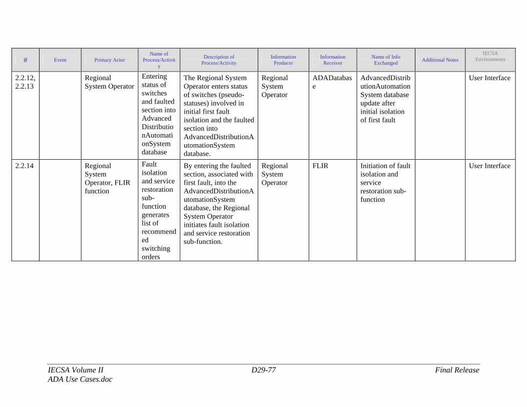
IECSA Volume II D29-77 Final Release ADA Use Cases.doc
# Event Primary Actor Name of
Process/Activity
Description of Process/Activity
Information Producer
Information Receiver
Name of Info Exchanged Additional Notes
IECSA Environments
2.2.12, 2.2.13
Regional System Operator
Entering status of switches and faulted section into AdvancedDistributionAutomationSystem database
The Regional System Operator enters status of switches (pseudo-statuses) involved in initial first fault isolation and the faulted section into AdvancedDistributionAutomationSystem database.
Regional System Operator
ADADatabase
AdvancedDistributionAutomationSystem database update after initial isolation of first fault
User Interface
2.2.14 Regional System Operator, FLIR function
Fault isolation and service restoration sub-function generates list of recommended switching orders
By entering the faulted section, associated with first fault, into the AdvancedDistributionAutomationSystem database, the Regional System Operator initiates fault isolation and service restoration sub-function.
Regional System Operator
FLIR Initiation of fault isolation and service restoration sub-function
User Interface
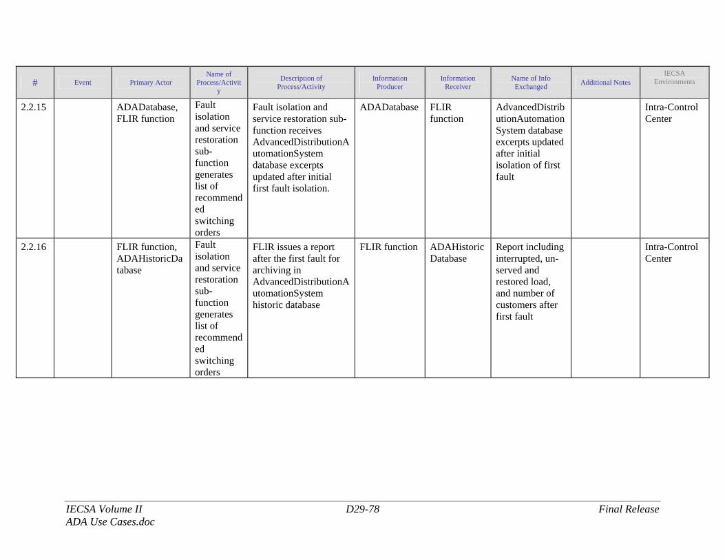
IECSA Volume II D29-78 Final Release ADA Use Cases.doc
# Event Primary Actor Name of
Process/Activity
Description of Process/Activity
Information Producer
Information Receiver
Name of Info Exchanged Additional Notes
IECSA Environments
2.2.15 ADADatabase, FLIR function
Fault isolation and service restoration sub-function generates list of recommended switching orders
Fault isolation and service restoration sub-function receives AdvancedDistributionAutomationSystem database excerpts updated after initial first fault isolation.
ADADatabase FLIR function
AdvancedDistributionAutomationSystem database excerpts updated after initial isolation of first fault
Intra-Control Center
2.2.16 FLIR function, ADAHistoricDatabase
Fault isolation and service restoration sub-function generates list of recommended switching orders
FLIR issues a report after the first fault for archiving in AdvancedDistributionAutomationSystem historic database
FLIR function ADAHistoricDatabase
Report including interrupted, un-served and restored load, and number of customers after first fault
Intra-Control Center
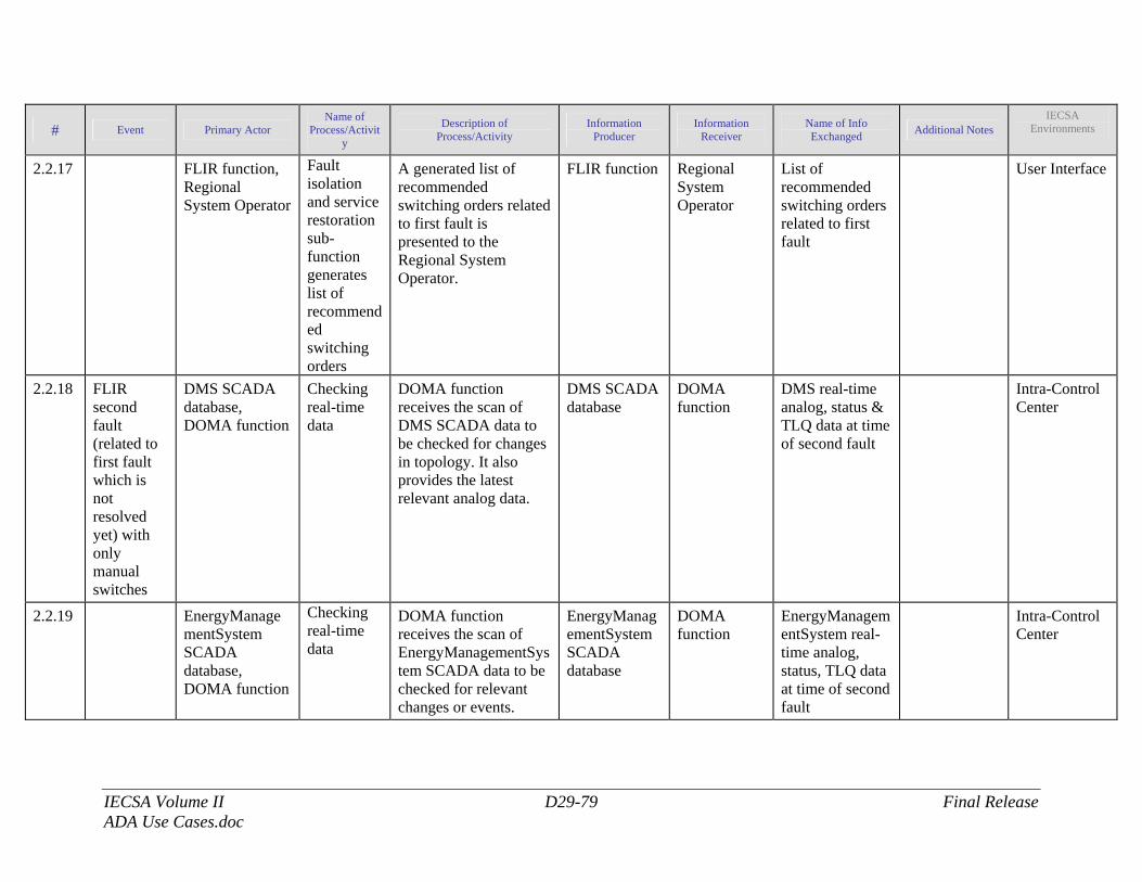
IECSA Volume II D29-79 Final Release ADA Use Cases.doc
# Event Primary Actor Name of
Process/Activity
Description of Process/Activity
Information Producer
Information Receiver
Name of Info Exchanged Additional Notes
IECSA Environments
2.2.17 FLIR function, Regional System Operator
Fault isolation and service restoration sub-function generates list of recommended switching orders
A generated list of recommended switching orders related to first fault is presented to the Regional System Operator.
FLIR function Regional System Operator
List of recommended switching orders related to first fault
User Interface
2.2.18 FLIR second fault (related to first fault which is not resolved yet) with only manual switches
DMS SCADA database, DOMA function
Checking real-time data
DOMA function receives the scan of DMS SCADA data to be checked for changes in topology. It also provides the latest relevant analog data.
DMS SCADA database
DOMA function
DMS real-time analog, status & TLQ data at time of second fault
Intra-Control Center
2.2.19 EnergyManagementSystem SCADA database, DOMA function
Checking real-time data
DOMA function receives the scan of EnergyManagementSystem SCADA data to be checked for relevant changes or events.
EnergyManagementSystem SCADA database
DOMA function
EnergyManagementSystem real-time analog, status, TLQ data at time of second fault
Intra-Control Center
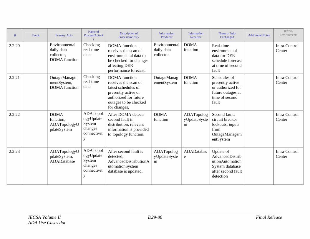
IECSA Volume II D29-80 Final Release ADA Use Cases.doc
# Event Primary Actor Name of
Process/Activity
Description of Process/Activity
Information Producer
Information Receiver
Name of Info Exchanged Additional Notes
IECSA Environments
2.2.20 Environmental daily data collector, DOMA function
Checking real-time data
DOMA function receives the scan of environmental data to be checked for changes affecting DER performance forecast.
Environmental daily data collector
DOMA function
Real-time environmental data for DER schedule forecast at time of second fault
Intra-Control Center
2.2.21 OutageManagementSystem, DOMA function
Checking real-time data
DOMA function receives the scan of latest schedules of presently active or authorized for future outages to be checked for changes.
OutageManagementSystem
DOMA function
Schedules of presently active or authorized for future outages at time of second fault
Intra-Control Center
2.2.22 DOMA function, ADATopologyUpdateSystem
ADATopologyUpdateSystem changes connectivity
After DOMA detects second fault in distribution, relevant information is provided to topology function.
DOMA function
ADATopologyUpdateSystem
Second fault: circuit breaker lockouts, inputs from OutageManagementSystem
Intra-Control Center
2.2.23 ADATopologyUpdateSystem, ADADatabase
ADATopologyUpdateSystem changes connectivity
After second fault is detected, AdvancedDistributionAutomationSystem database is updated.
ADATopologyUpdateSystem
ADADatabase
Update of AdvancedDistributionAutomationSystem database after second fault detection
Intra-Control Center
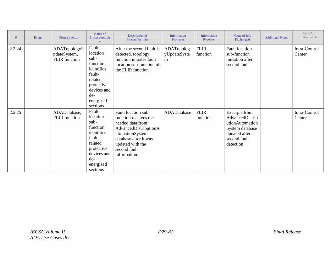
IECSA Volume II D29-81 Final Release ADA Use Cases.doc
# Event Primary Actor Name of
Process/Activity
Description of Process/Activity
Information Producer
Information Receiver
Name of Info Exchanged Additional Notes
IECSA Environments
2.2.24 ADATopologyUpdateSystem, FLIR function
Fault location sub-function identifies fault-related protective devices and de-energized sections
After the second fault is detected, topology function initiates fault location sub-function of the FLIR function.
ADATopologyUpdateSystem
FLIR function
Fault location sub-function initiation after second fault
Intra-Control Center
2.2.25 ADADatabase, FLIR function
Fault location sub-function identifies fault-related protective devices and de-energized sections
Fault location sub-function receives the needed data from AdvancedDistributionAutomationSystem database after it was updated with the second fault information.
ADADatabase FLIR function
Excerpts from AdvancedDistributionAutomationSystem database updated after second fault detection
Intra-Control Center
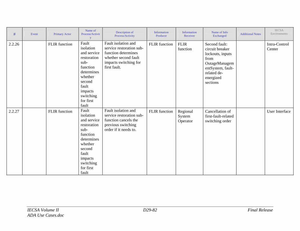
IECSA Volume II D29-82 Final Release ADA Use Cases.doc
# Event Primary Actor Name of
Process/Activity
Description of Process/Activity
Information Producer
Information Receiver
Name of Info Exchanged Additional Notes
IECSA Environments
2.2.26 FLIR function Fault isolation and service restoration sub-function determines whether second fault impacts switching for first fault
Fault isolation and service restoration sub-function determines whether second fault impacts switching for first fault.
FLIR function FLIR function
Second fault: circuit breaker lockouts, inputs from OutageManagementSystem, fault-related de-energized sections
Intra-Control Center
2.2.27 FLIR function Fault isolation and service restoration sub-function determines whether second fault impacts switching for first fault
Fault isolation and service restoration sub-function cancels the previous switching order if it needs to.
FLIR function Regional System Operator
Cancellation of first-fault-related switching order
User Interface
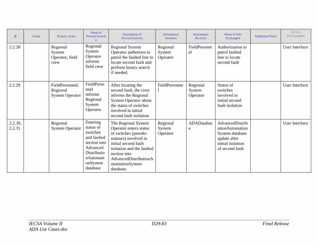
IECSA Volume II D29-83 Final Release ADA Use Cases.doc
# Event Primary Actor Name of
Process/Activity
Description of Process/Activity
Information Producer
Information Receiver
Name of Info Exchanged Additional Notes
IECSA Environments
2.2.28 Regional System Operator, field crew
Regional System Operator informs field crew
Regional System Operator authorizes to patrol the faulted line to locate second fault and perform binary search if needed.
Regional System Operator
FieldPersonnel
Authorization to patrol faulted line to locate second fault
User Interface
2.2.29 FieldPersonnel, Regional System Operator
FieldPersonnel informs Regional System Operator
After locating the second fault, the crew informs the Regional System Operator about the status of switches involved in initial second fault isolation.
FieldPersonnel
Regional System Operator
Status of switches involved in initial second fault isolation
User Interface
2.2.30, 2.2.31
Regional System Operator
Entering status of switches and faulted section into AdvancedDistributionAutomationSystem database
The Regional System Operator enters status of switches (pseudo-statuses) involved in initial second fault isolation and the faulted section into AdvancedDistributionAutomationSystem database.
Regional System Operator
ADADatabase
AdvancedDistributionAutomationSystem database update after initial isolation of second fault
User Interface
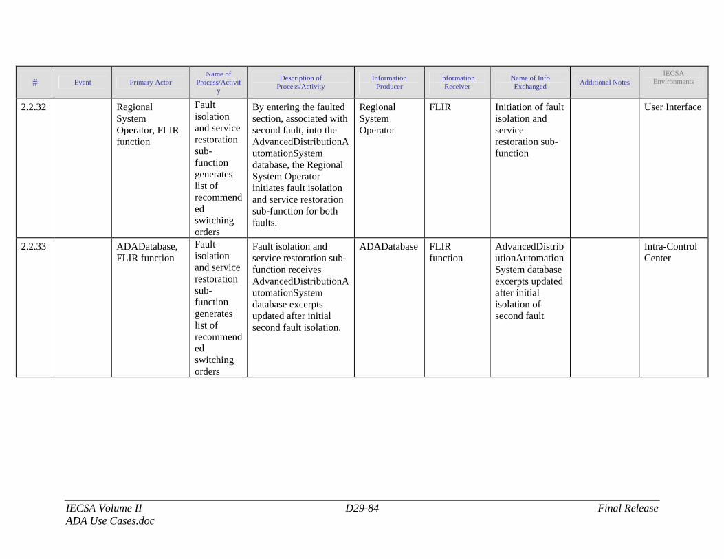
IECSA Volume II D29-84 Final Release ADA Use Cases.doc
# Event Primary Actor Name of
Process/Activity
Description of Process/Activity
Information Producer
Information Receiver
Name of Info Exchanged Additional Notes
IECSA Environments
2.2.32 Regional System Operator, FLIR function
Fault isolation and service restoration sub-function generates list of recommended switching orders
By entering the faulted section, associated with second fault, into the AdvancedDistributionAutomationSystem database, the Regional System Operator initiates fault isolation and service restoration sub-function for both faults.
Regional System Operator
FLIR Initiation of fault isolation and service restoration sub-function
User Interface
2.2.33 ADADatabase, FLIR function
Fault isolation and service restoration sub-function generates list of recommended switching orders
Fault isolation and service restoration sub-function receives AdvancedDistributionAutomationSystem database excerpts updated after initial second fault isolation.
ADADatabase FLIR function
AdvancedDistributionAutomationSystem database excerpts updated after initial isolation of second fault
Intra-Control Center
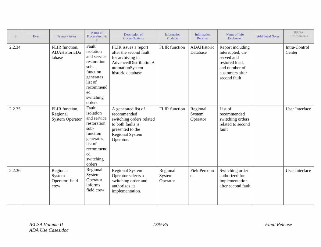
IECSA Volume II D29-85 Final Release ADA Use Cases.doc
# Event Primary Actor Name of
Process/Activity
Description of Process/Activity
Information Producer
Information Receiver
Name of Info Exchanged Additional Notes
IECSA Environments
2.2.34 FLIR function, ADAHistoricDatabase
Fault isolation and service restoration sub-function generates list of recommended switching orders
FLIR issues a report after the second fault for archiving in AdvancedDistributionAutomationSystem historic database
FLIR function ADAHistoricDatabase
Report including interrupted, un-served and restored load, and number of customers after second fault
Intra-Control Center
2.2.35 FLIR function, Regional System Operator
Fault isolation and service restoration sub-function generates list of recommended switching orders
A generated list of recommended switching orders related to both faults is presented to the Regional System Operator.
FLIR function Regional System Operator
List of recommended switching orders related to second fault
User Interface
2.2.36 Regional System Operator, field crew
Regional System Operator informs field crew
Regional System Operator selects a switching order and authorizes its implementation.
Regional System Operator
FieldPersonnel
Switching order authorized for implementation after second fault
User Interface
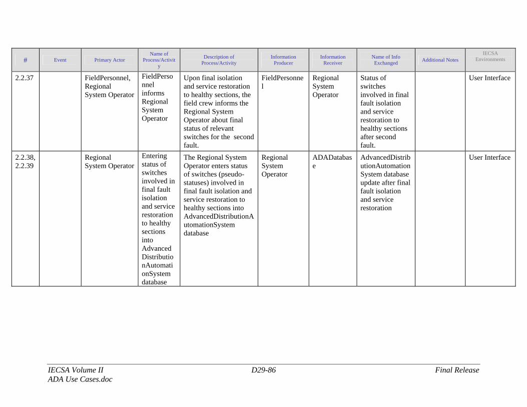
IECSA Volume II D29-86 Final Release ADA Use Cases.doc
# Event Primary Actor Name of
Process/Activity
Description of Process/Activity
Information Producer
Information Receiver
Name of Info Exchanged Additional Notes
IECSA Environments
2.2.37 FieldPersonnel, Regional System Operator
FieldPersonnel informs Regional System Operator
Upon final isolation and service restoration to healthy sections, the field crew informs the Regional System Operator about final status of relevant switches for the second fault.
FieldPersonnel
Regional System Operator
Status of switches involved in final fault isolation and service restoration to healthy sections after second fault.
User Interface
2.2.38, 2.2.39
Regional System Operator
Entering status of switches involved in final fault isolation and service restoration to healthy sections into AdvancedDistributionAutomationSystem database
The Regional System Operator enters status of switches (pseudo-statuses) involved in final fault isolation and service restoration to healthy sections into AdvancedDistributionAutomationSystem database
Regional System Operator
ADADatabase
AdvancedDistributionAutomationSystem database update after final fault isolation and service restoration
User Interface
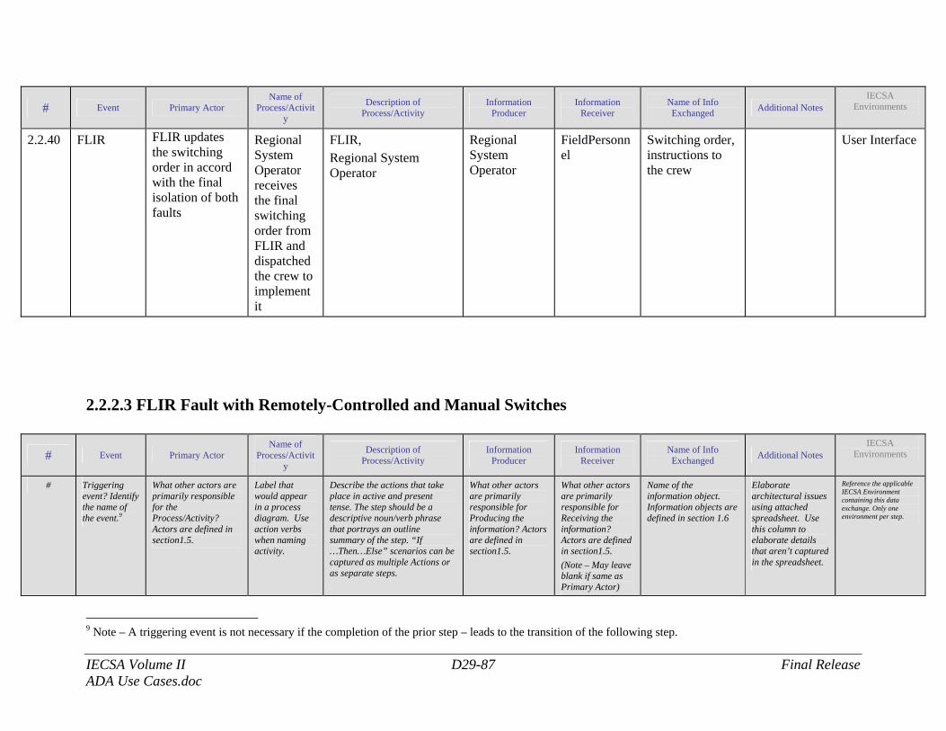
IECSA Volume II D29-87 Final Release ADA Use Cases.doc
# Event Primary Actor Name of
Process/Activity
Description of Process/Activity
Information Producer
Information Receiver
Name of Info Exchanged Additional Notes
IECSA Environments
2.2.40 FLIR FLIR updates the switching order in accord with the final isolation of both faults
Regional System Operator receives the final switching order from FLIR and dispatched the crew to implement it
FLIR, Regional System Operator
Regional System Operator
FieldPersonnel
Switching order, instructions to the crew
User Interface
2.2.2.3 FLIR Fault with Remotely-Controlled and Manual Switches
# Event Primary Actor Name of
Process/Activity
Description of Process/Activity
Information Producer
Information Receiver
Name of Info Exchanged Additional Notes
IECSA Environments
# Triggering event? Identify the name of the event.9
What other actors are primarily responsible for the Process/Activity? Actors are defined in section1.5.
Label that would appear in a process diagram. Use action verbs when naming activity.
Describe the actions that take place in active and present tense. The step should be a descriptive noun/verb phrase that portrays an outline summary of the step. “If …Then…Else” scenarios can be captured as multiple Actions or as separate steps.
What other actors are primarily responsible for Producing the information? Actors are defined in section1.5.
What other actors are primarily responsible for Receiving the information? Actors are defined in section1.5. (Note – May leave blank if same as Primary Actor)
Name of the information object. Information objects are defined in section 1.6
Elaborate architectural issues using attached spreadsheet. Use this column to elaborate details that aren’t captured in the spreadsheet.
Reference the applicable IECSA Environment containing this data exchange. Only one environment per step.
9 Note – A triggering event is not necessary if the completion of the prior step – leads to the transition of the following step.
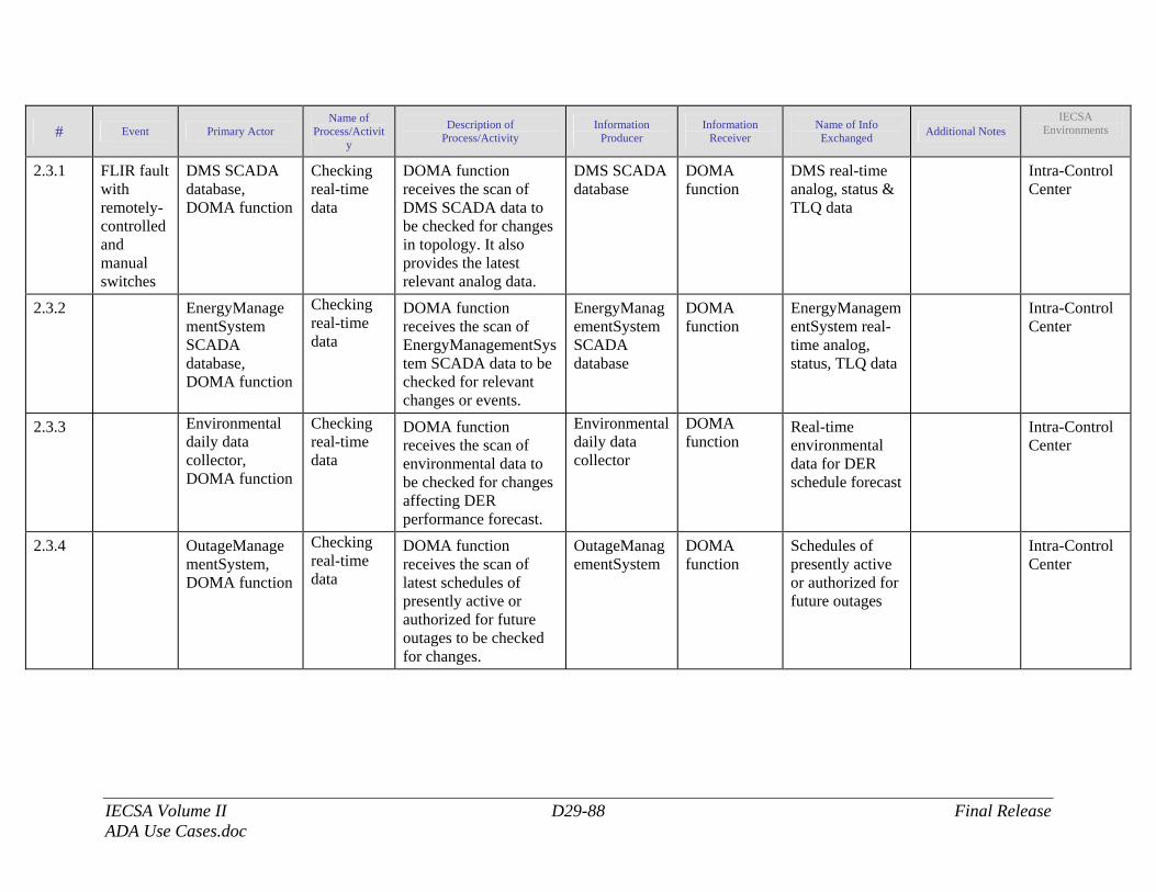
IECSA Volume II D29-88 Final Release ADA Use Cases.doc
# Event Primary Actor Name of
Process/Activity
Description of Process/Activity
Information Producer
Information Receiver
Name of Info Exchanged Additional Notes
IECSA Environments
2.3.1 FLIR fault with remotely-controlled and manual switches
DMS SCADA database, DOMA function
Checking real-time data
DOMA function receives the scan of DMS SCADA data to be checked for changes in topology. It also provides the latest relevant analog data.
DMS SCADA database
DOMA function
DMS real-time analog, status & TLQ data
Intra-Control Center
2.3.2 EnergyManagementSystem SCADA database, DOMA function
Checking real-time data
DOMA function receives the scan of EnergyManagementSystem SCADA data to be checked for relevant changes or events.
EnergyManagementSystem SCADA database
DOMA function
EnergyManagementSystem real-time analog, status, TLQ data
Intra-Control Center
2.3.3 Environmental daily data collector, DOMA function
Checking real-time data
DOMA function receives the scan of environmental data to be checked for changes affecting DER performance forecast.
Environmental daily data collector
DOMA function
Real-time environmental data for DER schedule forecast
Intra-Control Center
2.3.4 OutageManagementSystem, DOMA function
Checking real-time data
DOMA function receives the scan of latest schedules of presently active or authorized for future outages to be checked for changes.
OutageManagementSystem
DOMA function
Schedules of presently active or authorized for future outages
Intra-Control Center
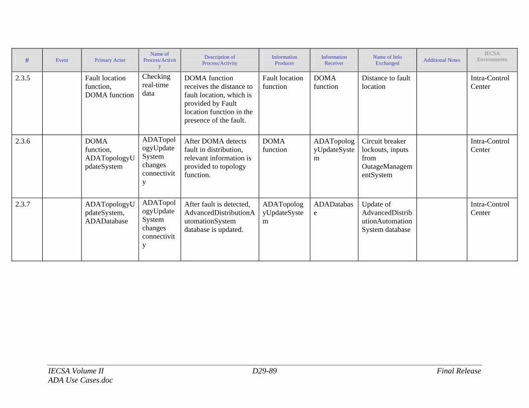
IECSA Volume II D29-89 Final Release ADA Use Cases.doc
# Event Primary Actor Name of
Process/Activity
Description of Process/Activity
Information Producer
Information Receiver
Name of Info Exchanged Additional Notes
IECSA Environments
2.3.5 Fault location function, DOMA function
Checking real-time data
DOMA function receives the distance to fault location, which is provided by Fault location function in the presence of the fault.
Fault location function
DOMA function
Distance to fault location
Intra-Control Center
2.3.6 DOMA function, ADATopologyUpdateSystem
ADATopologyUpdateSystem changes connectivity
After DOMA detects fault in distribution, relevant information is provided to topology function.
DOMA function
ADATopologyUpdateSystem
Circuit breaker lockouts, inputs from OutageManagementSystem
Intra-Control Center
2.3.7 ADATopologyUpdateSystem, ADADatabase
ADATopologyUpdateSystem changes connectivity
After fault is detected, AdvancedDistributionAutomationSystem database is updated.
ADATopologyUpdateSystem
ADADatabase
Update of AdvancedDistributionAutomationSystem database
Intra-Control Center
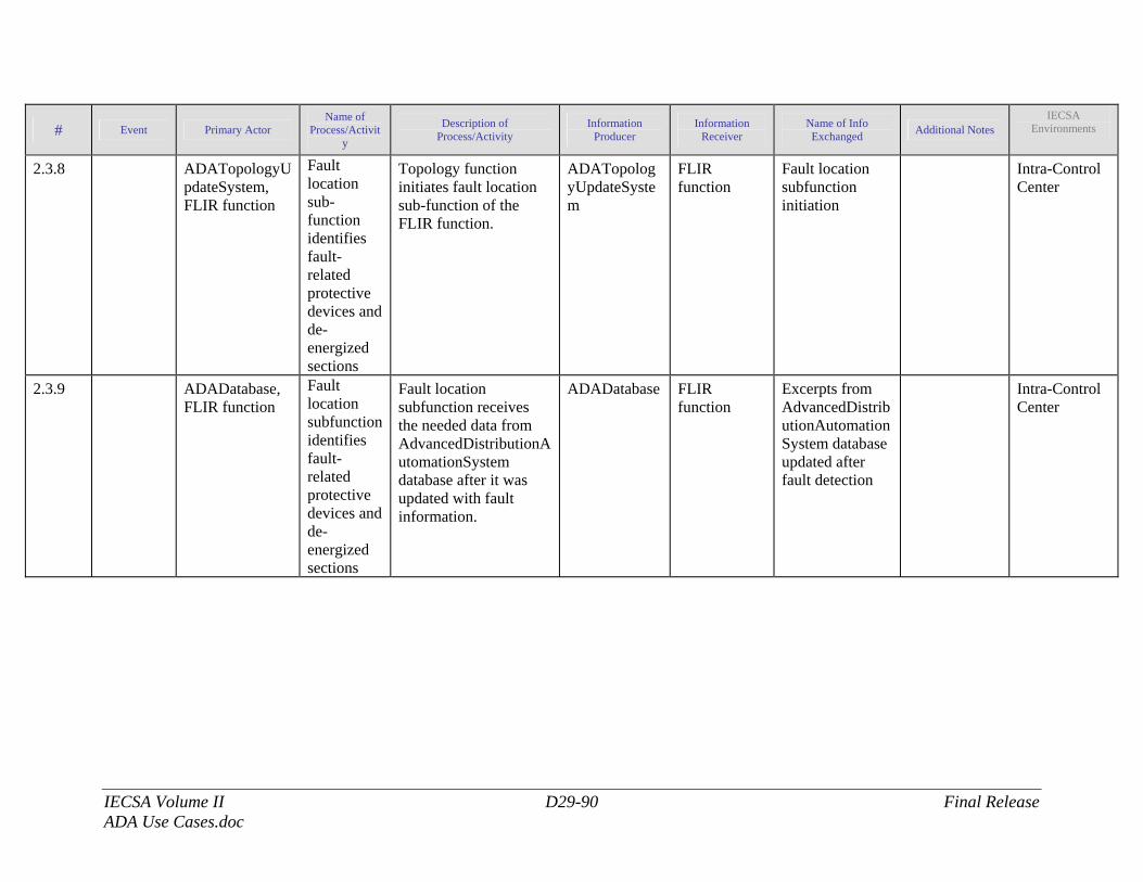
IECSA Volume II D29-90 Final Release ADA Use Cases.doc
# Event Primary Actor Name of
Process/Activity
Description of Process/Activity
Information Producer
Information Receiver
Name of Info Exchanged Additional Notes
IECSA Environments
2.3.8 ADATopologyUpdateSystem, FLIR function
Fault location sub-function identifies fault-related protective devices and de-energized sections
Topology function initiates fault location sub-function of the FLIR function.
ADATopologyUpdateSystem
FLIR function
Fault location subfunction initiation
Intra-Control Center
2.3.9 ADADatabase, FLIR function
Fault location subfunction identifies fault-related protective devices and de-energized sections
Fault location subfunction receives the needed data from AdvancedDistributionAutomationSystem database after it was updated with fault information.
ADADatabase FLIR function
Excerpts from AdvancedDistributionAutomationSystem database updated after fault detection
Intra-Control Center
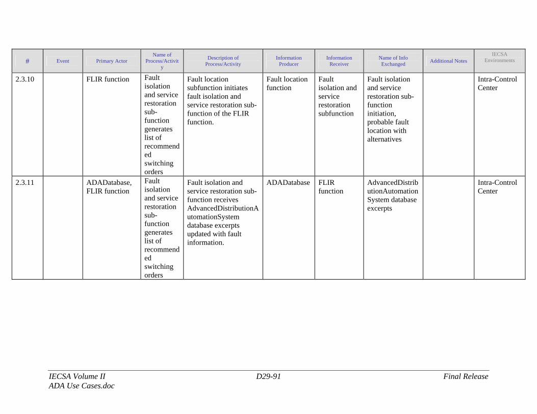
IECSA Volume II D29-91 Final Release ADA Use Cases.doc
# Event Primary Actor Name of
Process/Activity
Description of Process/Activity
Information Producer
Information Receiver
Name of Info Exchanged Additional Notes
IECSA Environments
2.3.10 FLIR function Fault isolation and service restoration sub-function generates list of recommended switching orders
Fault location subfunction initiates fault isolation and service restoration sub-function of the FLIR function.
Fault location function
Fault isolation and service restoration subfunction
Fault isolation and service restoration sub-function initiation, probable fault location with alternatives
Intra-Control Center
2.3.11 ADADatabase, FLIR function
Fault isolation and service restoration sub-function generates list of recommended switching orders
Fault isolation and service restoration sub-function receives AdvancedDistributionAutomationSystem database excerpts updated with fault information.
ADADatabase FLIR function
AdvancedDistributionAutomationSystem database excerpts
Intra-Control Center
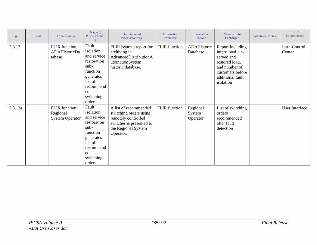
IECSA Volume II D29-92 Final Release ADA Use Cases.doc
# Event Primary Actor Name of
Process/Activity
Description of Process/Activity
Information Producer
Information Receiver
Name of Info Exchanged Additional Notes
IECSA Environments
2.3.12 FLIR function, ADAHistoricDatabase
Fault isolation and service restoration sub-function generates list of recommended switching orders
FLIR issues a report for archiving in AdvancedDistributionAutomationSystem historic database.
FLIR function ADAHistoricDatabase
Report including interrupted, un-served and restored load, and number of customers before additional fault isolation
Intra-Control Center
2.3.13a FLIR function, Regional System Operator
Fault isolation and service restoration sub-function generates list of recommended switching orders
A list of recommended switching orders using remotely controlled switches is presented to the Regional System Operator.
FLIR function Regional System Operator
List of switching orders recommended after fault detection
User Interface
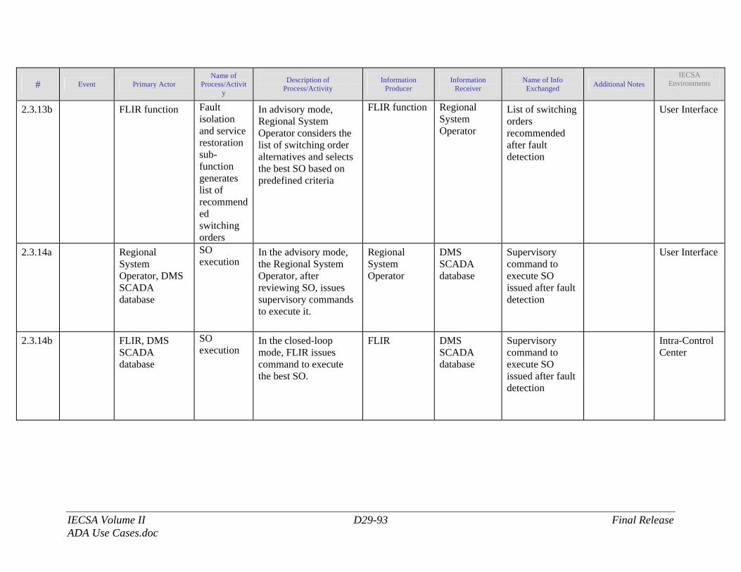
IECSA Volume II D29-93 Final Release ADA Use Cases.doc
# Event Primary Actor Name of
Process/Activity
Description of Process/Activity
Information Producer
Information Receiver
Name of Info Exchanged Additional Notes
IECSA Environments
2.3.13b FLIR function Fault isolation and service restoration sub-function generates list of recommended switching orders
In advisory mode, Regional System Operator considers the list of switching order alternatives and selects the best SO based on predefined criteria
FLIR function Regional System Operator
List of switching orders recommended after fault detection
User Interface
2.3.14a Regional System Operator, DMS SCADA database
SO execution
In the advisory mode, the Regional System Operator, after reviewing SO, issues supervisory commands to execute it.
Regional System Operator
DMS SCADA database
Supervisory command to execute SO issued after fault detection
User Interface
2.3.14b FLIR, DMS SCADA database
SO execution
In the closed-loop mode, FLIR issues command to execute the best SO.
FLIR DMS SCADA database
Supervisory command to execute SO issued after fault detection
Intra-Control Center
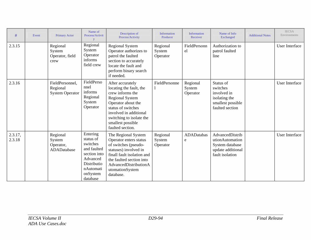
IECSA Volume II D29-94 Final Release ADA Use Cases.doc
# Event Primary Actor Name of
Process/Activity
Description of Process/Activity
Information Producer
Information Receiver
Name of Info Exchanged Additional Notes
IECSA Environments
2.3.15 Regional System Operator, field crew
Regional System Operator informs field crew
Regional System Operator authorizes to patrol the faulted section to accurately locate the fault and perform binary search if needed.
Regional System Operator
FieldPersonnel
Authorization to patrol faulted line
User Interface
2.3.16 FieldPersonnel, Regional System Operator
FieldPersonnel informs Regional System Operator
After accurately locating the fault, the crew informs the Regional System Operator about the status of switches involved in additional switching to isolate the smallest possible faulted section.
FieldPersonnel
Regional System Operator
Status of switches involved in isolating the smallest possible faulted section
User Interface
2.3.17, 2.3.18
Regional System Operator, ADADatabase
Entering status of switches and faulted section into AdvancedDistributionAutomationSystem database
The Regional System Operator enters status of switches (pseudo-statuses) involved in finall fault isolation and the faulted section into AdvancedDistributionAutomationSystem database.
Regional System Operator
ADADatabase
AdvancedDistributionAutomationSystem database update additional fault isolation
User Interface
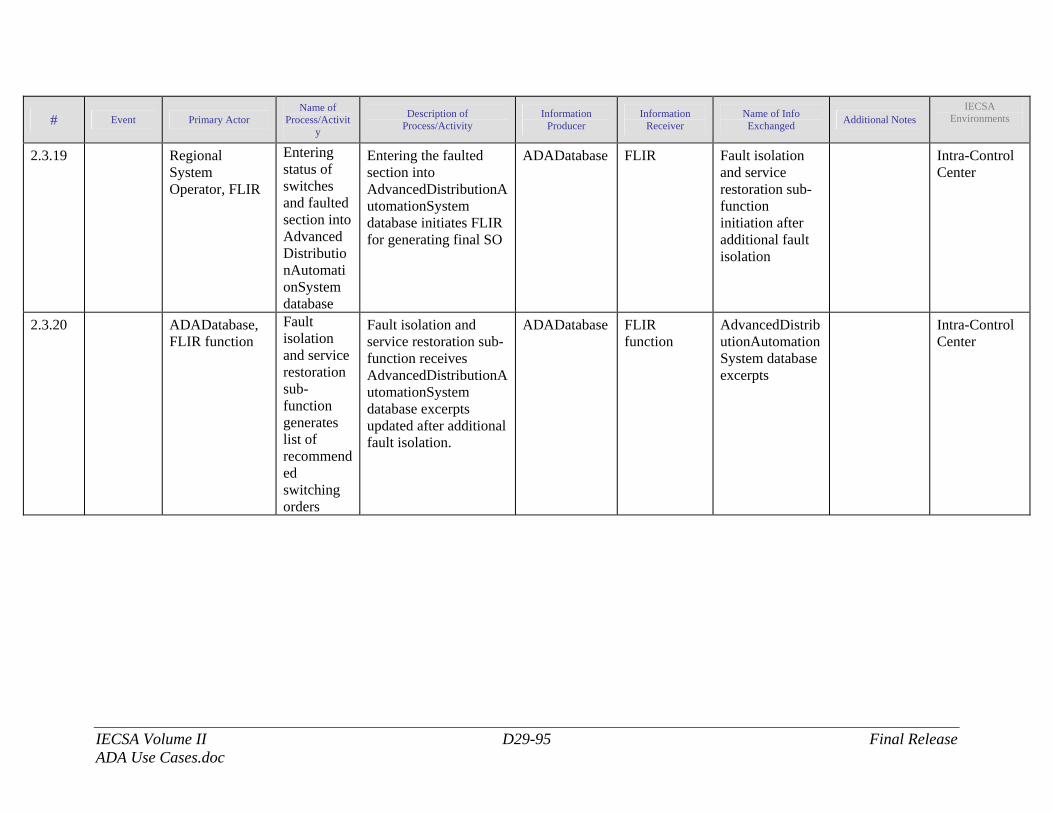
IECSA Volume II D29-95 Final Release ADA Use Cases.doc
# Event Primary Actor Name of
Process/Activity
Description of Process/Activity
Information Producer
Information Receiver
Name of Info Exchanged Additional Notes
IECSA Environments
2.3.19 Regional System Operator, FLIR
Entering status of switches and faulted section into AdvancedDistributionAutomationSystem database
Entering the faulted section into AdvancedDistributionAutomationSystem database initiates FLIR for generating final SO
ADADatabase FLIR Fault isolation and service restoration sub-function initiation after additional fault isolation
Intra-Control Center
2.3.20 ADADatabase, FLIR function
Fault isolation and service restoration sub-function generates list of recommended switching orders
Fault isolation and service restoration sub-function receives AdvancedDistributionAutomationSystem database excerpts updated after additional fault isolation.
ADADatabase FLIR function
AdvancedDistributionAutomationSystem database excerpts
Intra-Control Center
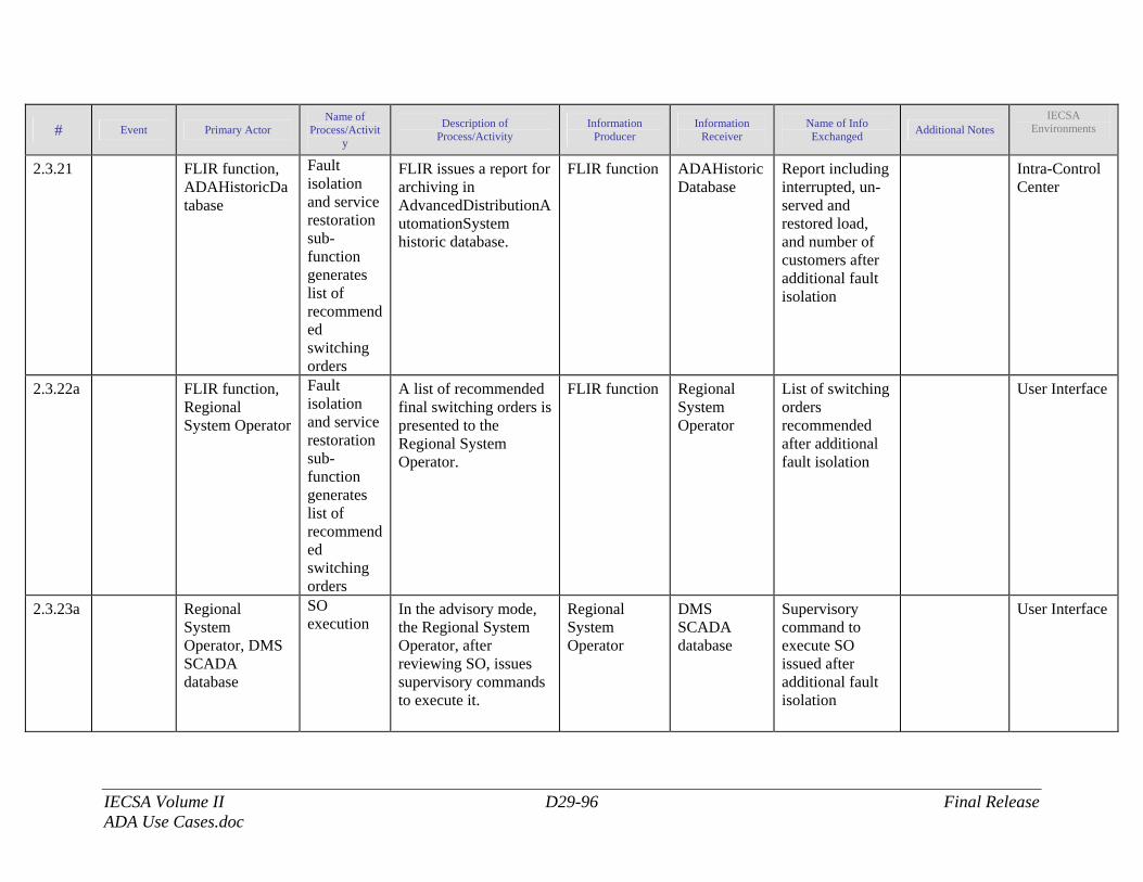
IECSA Volume II D29-96 Final Release ADA Use Cases.doc
# Event Primary Actor Name of
Process/Activity
Description of Process/Activity
Information Producer
Information Receiver
Name of Info Exchanged Additional Notes
IECSA Environments
2.3.21 FLIR function, ADAHistoricDatabase
Fault isolation and service restoration sub-function generates list of recommended switching orders
FLIR issues a report for archiving in AdvancedDistributionAutomationSystem historic database.
FLIR function ADAHistoricDatabase
Report including interrupted, un-served and restored load, and number of customers after additional fault isolation
Intra-Control Center
2.3.22a FLIR function, Regional System Operator
Fault isolation and service restoration sub-function generates list of recommended switching orders
A list of recommended final switching orders is presented to the Regional System Operator.
FLIR function Regional System Operator
List of switching orders recommended after additional fault isolation
User Interface
2.3.23a Regional System Operator, DMS SCADA database
SO execution
In the advisory mode, the Regional System Operator, after reviewing SO, issues supervisory commands to execute it.
Regional System Operator
DMS SCADA database
Supervisory command to execute SO issued after additional fault isolation
User Interface
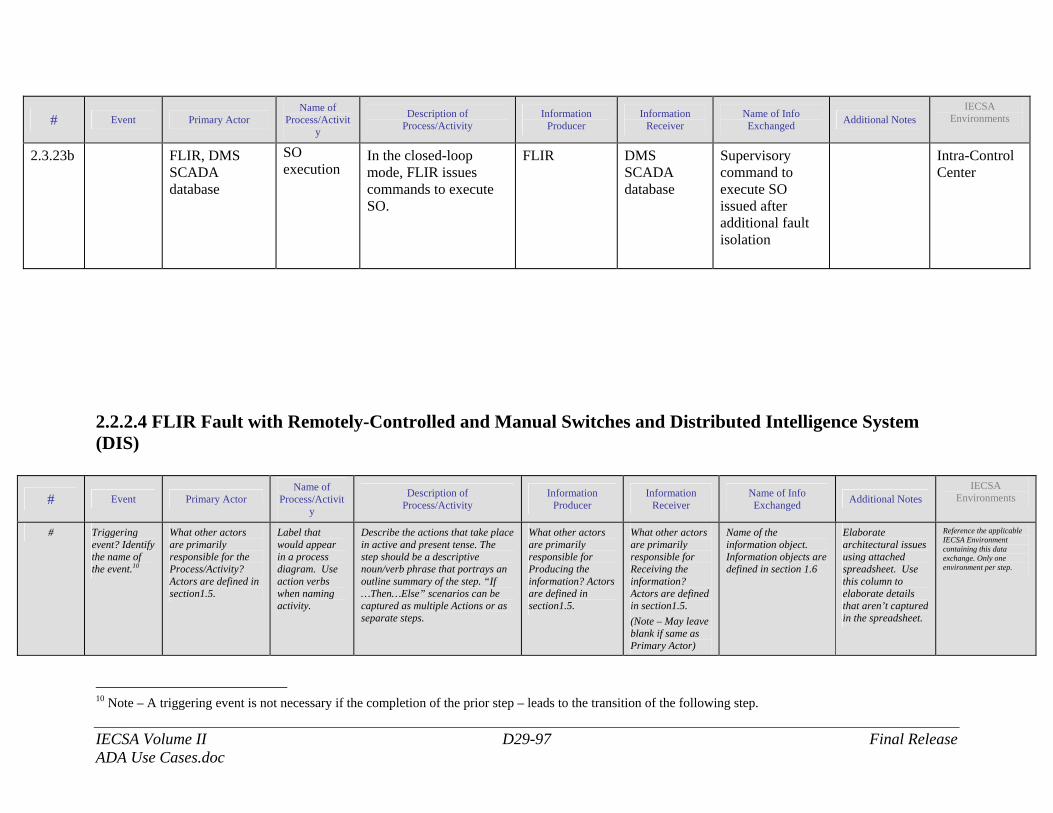
IECSA Volume II D29-97 Final Release ADA Use Cases.doc
# Event Primary Actor Name of
Process/Activity
Description of Process/Activity
Information Producer
Information Receiver
Name of Info Exchanged Additional Notes
IECSA Environments
2.3.23b FLIR, DMS SCADA database
SO execution
In the closed-loop mode, FLIR issues commands to execute SO.
FLIR DMS SCADA database
Supervisory command to execute SO issued after additional fault isolation
Intra-Control Center
2.2.2.4 FLIR Fault with Remotely-Controlled and Manual Switches and Distributed Intelligence System (DIS)
# Event Primary Actor Name of
Process/Activity
Description of Process/Activity
Information Producer
Information Receiver
Name of Info Exchanged Additional Notes
IECSA Environments
# Triggering event? Identify the name of the event.10
What other actors are primarily responsible for the Process/Activity? Actors are defined in section1.5.
Label that would appear in a process diagram. Use action verbs when naming activity.
Describe the actions that take place in active and present tense. The step should be a descriptive noun/verb phrase that portrays an outline summary of the step. “If …Then…Else” scenarios can be captured as multiple Actions or as separate steps.
What other actors are primarily responsible for Producing the information? Actors are defined in section1.5.
What other actors are primarily responsible for Receiving the information? Actors are defined in section1.5. (Note – May leave blank if same as Primary Actor)
Name of the information object. Information objects are defined in section 1.6
Elaborate architectural issues using attached spreadsheet. Use this column to elaborate details that aren’t captured in the spreadsheet.
Reference the applicable IECSA Environment containing this data exchange. Only one environment per step.
10 Note – A triggering event is not necessary if the completion of the prior step – leads to the transition of the following step.
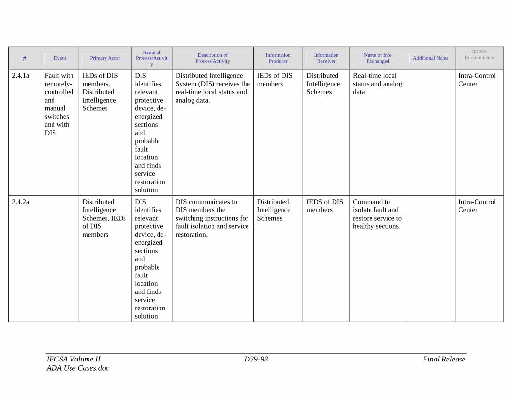
IECSA Volume II D29-98 Final Release ADA Use Cases.doc
# Event Primary Actor Name of
Process/Activity
Description of Process/Activity
Information Producer
Information Receiver
Name of Info Exchanged Additional Notes
IECSA Environments
2.4.1a Fault with remotely-controlled and manual switches and with DIS
IEDs of DIS members, Distributed Intelligence Schemes
DIS identifies relevant protective device, de-energized sections and probable fault location and finds service restoration solution
Distributed Intelligence System (DIS) receives the real-time local status and analog data.
IEDs of DIS members
Distributed Intelligence Schemes
Real-time local status and analog data
Intra-Control Center
2.4.2a Distributed Intelligence Schemes, IEDs of DIS members
DIS identifies relevant protective device, de-energized sections and probable fault location and finds service restoration solution
DIS communicates to DIS members the switching instructions for fault isolation and service restoration.
Distributed Intelligence Schemes
IEDS of DIS members
Command to isolate fault and restore service to healthy sections.
Intra-Control Center
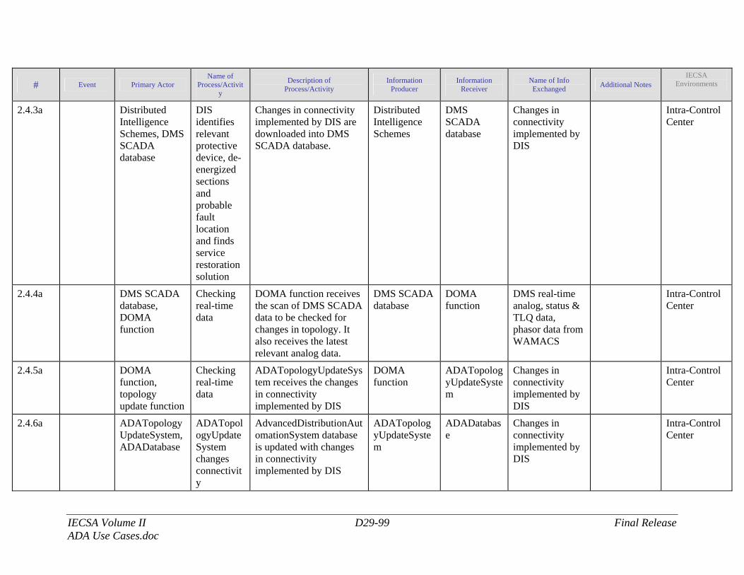
IECSA Volume II D29-99 Final Release ADA Use Cases.doc
# Event Primary Actor Name of
Process/Activity
Description of Process/Activity
Information Producer
Information Receiver
Name of Info Exchanged Additional Notes
IECSA Environments
2.4.3a Distributed Intelligence Schemes, DMS SCADA database
DIS identifies relevant protective device, de-energized sections and probable fault location and finds service restoration solution
Changes in connectivity implemented by DIS are downloaded into DMS SCADA database.
Distributed Intelligence Schemes
DMS SCADA database
Changes in connectivity implemented by DIS
Intra-Control Center
2.4.4a DMS SCADA database, DOMA function
Checking real-time data
DOMA function receives the scan of DMS SCADA data to be checked for changes in topology. It also receives the latest relevant analog data.
DMS SCADA database
DOMA function
DMS real-time analog, status & TLQ data, phasor data from WAMACS
Intra-Control Center
2.4.5a DOMA function, topology update function
Checking real-time data
ADATopologyUpdateSystem receives the changes in connectivity implemented by DIS
DOMA function
ADATopologyUpdateSystem
Changes in connectivity implemented by DIS
Intra-Control Center
2.4.6a ADATopologyUpdateSystem, ADADatabase
ADATopologyUpdateSystem changes connectivity
AdvancedDistributionAutomationSystem database is updated with changes in connectivity implemented by DIS
ADATopologyUpdateSystem
ADADatabase
Changes in connectivity implemented by DIS
Intra-Control Center
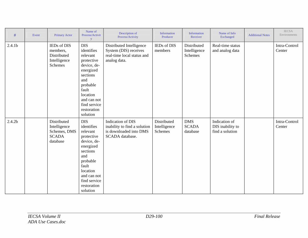
IECSA Volume II D29-100 Final Release ADA Use Cases.doc
# Event Primary Actor Name of
Process/Activity
Description of Process/Activity
Information Producer
Information Receiver
Name of Info Exchanged Additional Notes
IECSA Environments
2.4.1b IEDs of DIS members, Distributed Intelligence Schemes
DIS identifies relevant protective device, de-energized sections and probable fault location and can not find service restoration solution
Distributed Intelligence System (DIS) receives real-time local status and analog data.
IEDs of DIS members
Distributed Intelligence Schemes
Real-time status and analog data
Intra-Control Center
2.4.2b Distributed Intelligence Schemes, DMS SCADA database
DIS identifies relevant protective device, de-energized sections and probable fault location and can not find service restoration solution
Indication of DIS inability to find a solution is downloaded into DMS SCADA database.
Distributed Intelligence Schemes
DMS SCADA database
Indication of DIS inability to find a solution
Intra-Control Center
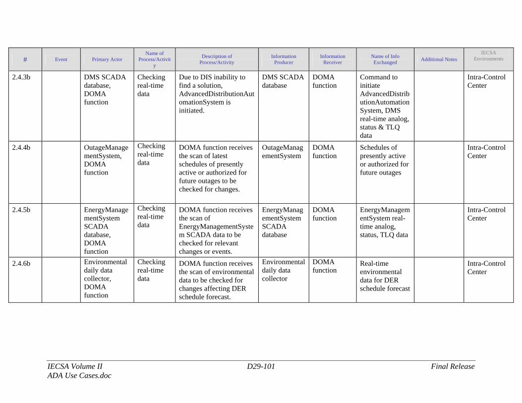
IECSA Volume II D29-101 Final Release ADA Use Cases.doc
# Event Primary Actor Name of
Process/Activity
Description of Process/Activity
Information Producer
Information Receiver
Name of Info Exchanged Additional Notes
IECSA Environments
2.4.3b DMS SCADA database, DOMA function
Checking real-time data
Due to DIS inability to find a solution, AdvancedDistributionAutomationSystem is initiated.
DMS SCADA database
DOMA function
Command to initiate AdvancedDistributionAutomationSystem, DMS real-time analog, status & TLQ data
Intra-Control Center
2.4.4b OutageManagementSystem, DOMA function
Checking real-time data
DOMA function receives the scan of latest schedules of presently active or authorized for future outages to be checked for changes.
OutageManagementSystem
DOMA function
Schedules of presently active or authorized for future outages
Intra-Control Center
2.4.5b EnergyManagementSystem SCADA database, DOMA function
Checking real-time data
DOMA function receives the scan of EnergyManagementSystem SCADA data to be checked for relevant changes or events.
EnergyManagementSystem SCADA database
DOMA function
EnergyManagementSystem real-time analog, status, TLQ data
Intra-Control Center
2.4.6b Environmental daily data collector, DOMA function
Checking real-time data
DOMA function receives the scan of environmental data to be checked for changes affecting DER schedule forecast.
Environmental daily data collector
DOMA function
Real-time environmental data for DER schedule forecast
Intra-Control Center
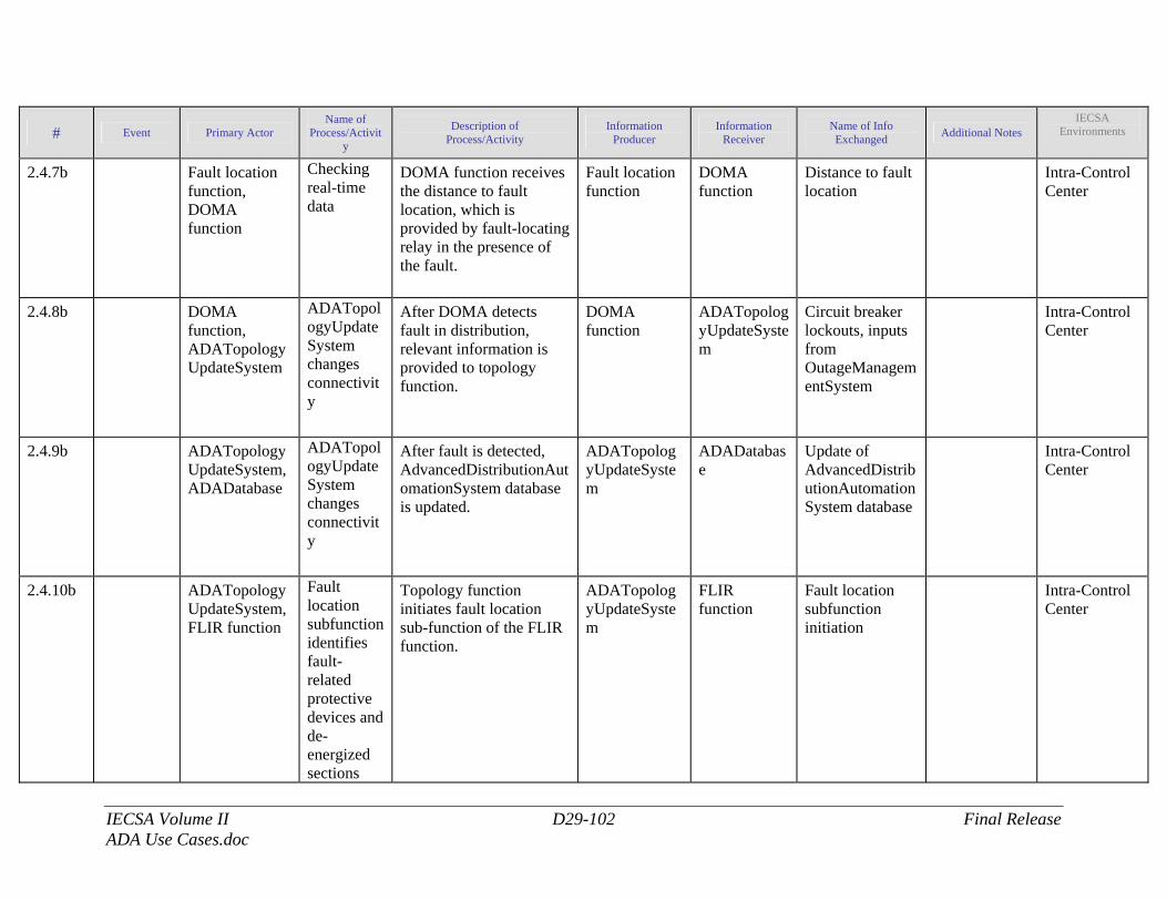
IECSA Volume II D29-102 Final Release ADA Use Cases.doc
# Event Primary Actor Name of
Process/Activity
Description of Process/Activity
Information Producer
Information Receiver
Name of Info Exchanged Additional Notes
IECSA Environments
2.4.7b Fault location function, DOMA function
Checking real-time data
DOMA function receives the distance to fault location, which is provided by fault-locating relay in the presence of the fault.
Fault location function
DOMA function
Distance to fault location
Intra-Control Center
2.4.8b DOMA function, ADATopologyUpdateSystem
ADATopologyUpdateSystem changes connectivity
After DOMA detects fault in distribution, relevant information is provided to topology function.
DOMA function
ADATopologyUpdateSystem
Circuit breaker lockouts, inputs from OutageManagementSystem
Intra-Control Center
2.4.9b ADATopologyUpdateSystem, ADADatabase
ADATopologyUpdateSystem changes connectivity
After fault is detected, AdvancedDistributionAutomationSystem database is updated.
ADATopologyUpdateSystem
ADADatabase
Update of AdvancedDistributionAutomationSystem database
Intra-Control Center
2.4.10b ADATopologyUpdateSystem, FLIR function
Fault location subfunction identifies fault-related protective devices and de-energized sections
Topology function initiates fault location sub-function of the FLIR function.
ADATopologyUpdateSystem
FLIR function
Fault location subfunction initiation
Intra-Control Center
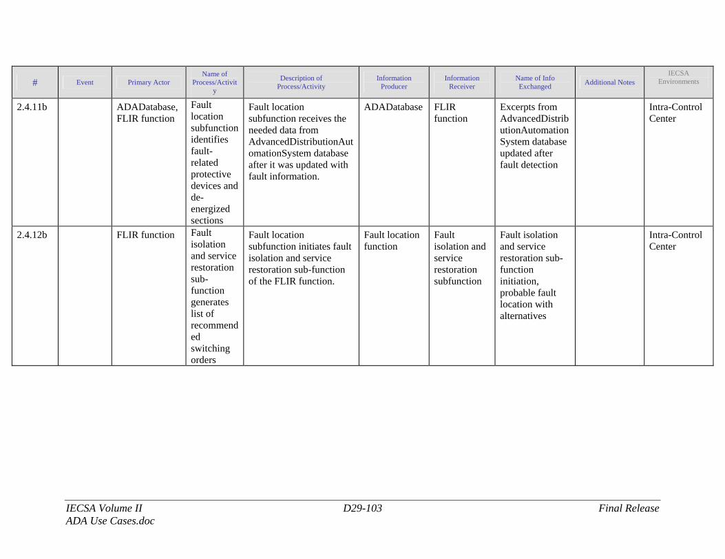
IECSA Volume II D29-103 Final Release ADA Use Cases.doc
# Event Primary Actor Name of
Process/Activity
Description of Process/Activity
Information Producer
Information Receiver
Name of Info Exchanged Additional Notes
IECSA Environments
2.4.11b ADADatabase, FLIR function
Fault location subfunction identifies fault-related protective devices and de-energized sections
Fault location subfunction receives the needed data from AdvancedDistributionAutomationSystem database after it was updated with fault information.
ADADatabase FLIR function
Excerpts from AdvancedDistributionAutomationSystem database updated after fault detection
Intra-Control Center
2.4.12b FLIR function Fault isolation and service restoration sub-function generates list of recommended switching orders
Fault location subfunction initiates fault isolation and service restoration sub-function of the FLIR function.
Fault location function
Fault isolation and service restoration subfunction
Fault isolation and service restoration sub-function initiation, probable fault location with alternatives
Intra-Control Center
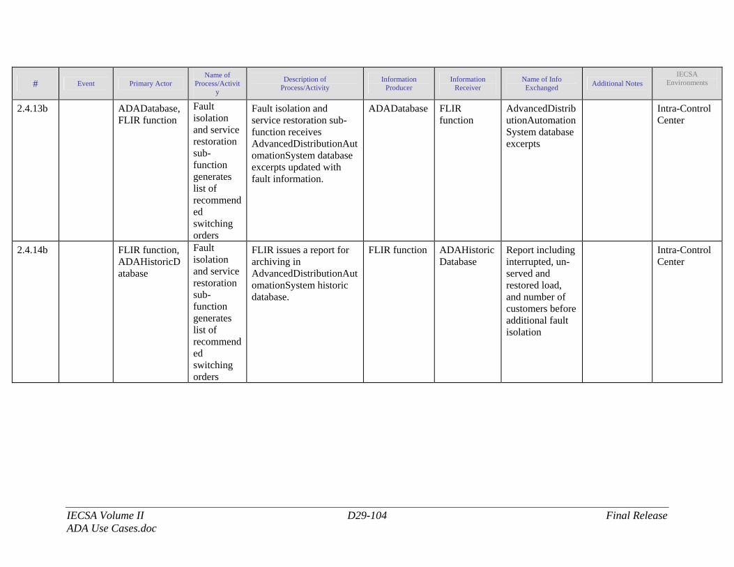
IECSA Volume II D29-104 Final Release ADA Use Cases.doc
# Event Primary Actor Name of
Process/Activity
Description of Process/Activity
Information Producer
Information Receiver
Name of Info Exchanged Additional Notes
IECSA Environments
2.4.13b ADADatabase, FLIR function
Fault isolation and service restoration sub-function generates list of recommended switching orders
Fault isolation and service restoration sub-function receives AdvancedDistributionAutomationSystem database excerpts updated with fault information.
ADADatabase FLIR function
AdvancedDistributionAutomationSystem database excerpts
Intra-Control Center
2.4.14b FLIR function, ADAHistoricDatabase
Fault isolation and service restoration sub-function generates list of recommended switching orders
FLIR issues a report for archiving in AdvancedDistributionAutomationSystem historic database.
FLIR function ADAHistoricDatabase
Report including interrupted, un-served and restored load, and number of customers before additional fault isolation
Intra-Control Center
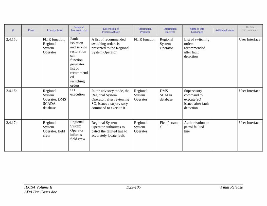
IECSA Volume II D29-105 Final Release ADA Use Cases.doc
# Event Primary Actor Name of
Process/Activity
Description of Process/Activity
Information Producer
Information Receiver
Name of Info Exchanged Additional Notes
IECSA Environments
2.4.15b FLIR function, Regional System Operator
Fault isolation and service restoration sub-function generates list of recommended switching orders
A list of recommended switching orders is presented to the Regional System Operator.
FLIR function Regional System Operator
List of switching orders recommended after fault detection
User Interface
2.4.16b Regional System Operator, DMS SCADA database
SO execution
In the advisory mode, the Regional System Operator, after reviewing SO, issues a supervisory command to execute it.
Regional System Operator
DMS SCADA database
Supervisory command to execute SO issued after fault detection
User Interface
2.4.17b Regional System Operator, field crew
Regional System Operator informs field crew
Regional System Operator authorizes to patrol the faulted line to accurately locate fault.
Regional System Operator
FieldPersonnel
Authorization to patrol faulted line
User Interface
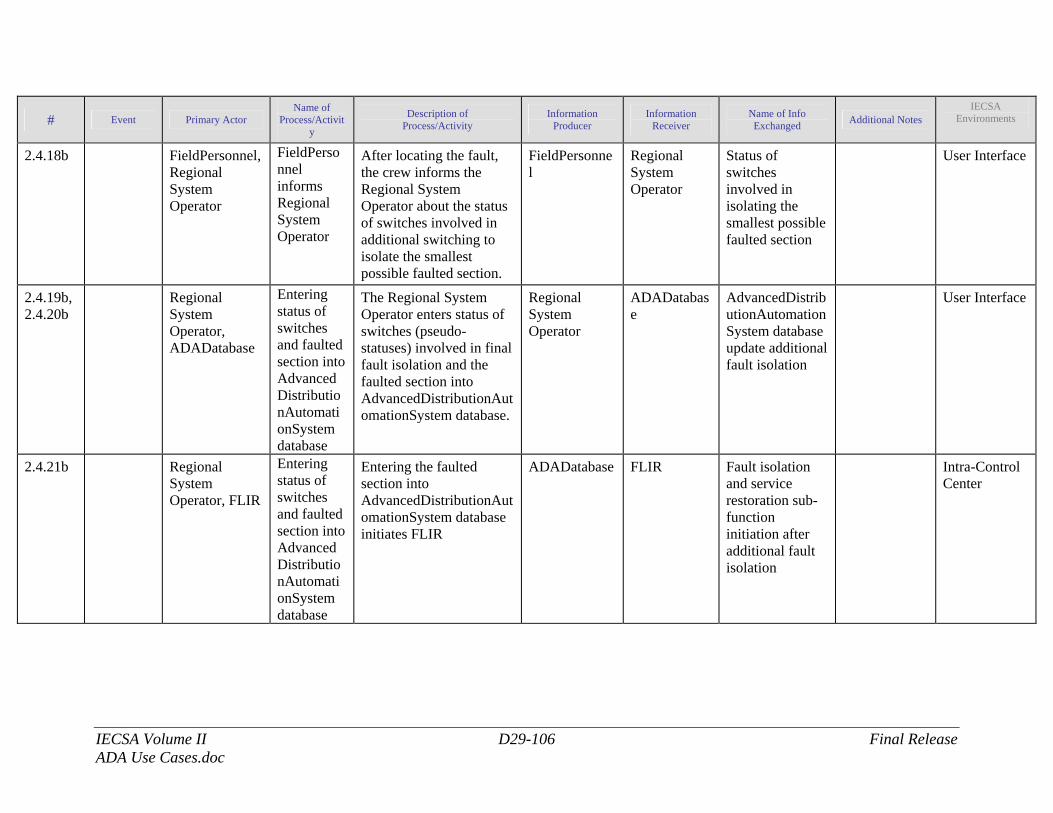
IECSA Volume II D29-106 Final Release ADA Use Cases.doc
# Event Primary Actor Name of
Process/Activity
Description of Process/Activity
Information Producer
Information Receiver
Name of Info Exchanged Additional Notes
IECSA Environments
2.4.18b FieldPersonnel, Regional System Operator
FieldPersonnel informs Regional System Operator
After locating the fault, the crew informs the Regional System Operator about the status of switches involved in additional switching to isolate the smallest possible faulted section.
FieldPersonnel
Regional System Operator
Status of switches involved in isolating the smallest possible faulted section
User Interface
2.4.19b, 2.4.20b
Regional System Operator, ADADatabase
Entering status of switches and faulted section into AdvancedDistributionAutomationSystem database
The Regional System Operator enters status of switches (pseudo-statuses) involved in final fault isolation and the faulted section into AdvancedDistributionAutomationSystem database.
Regional System Operator
ADADatabase
AdvancedDistributionAutomationSystem database update additional fault isolation
User Interface
2.4.21b Regional System Operator, FLIR
Entering status of switches and faulted section into AdvancedDistributionAutomationSystem database
Entering the faulted section into AdvancedDistributionAutomationSystem database initiates FLIR
ADADatabase FLIR Fault isolation and service restoration sub-function initiation after additional fault isolation
Intra-Control Center
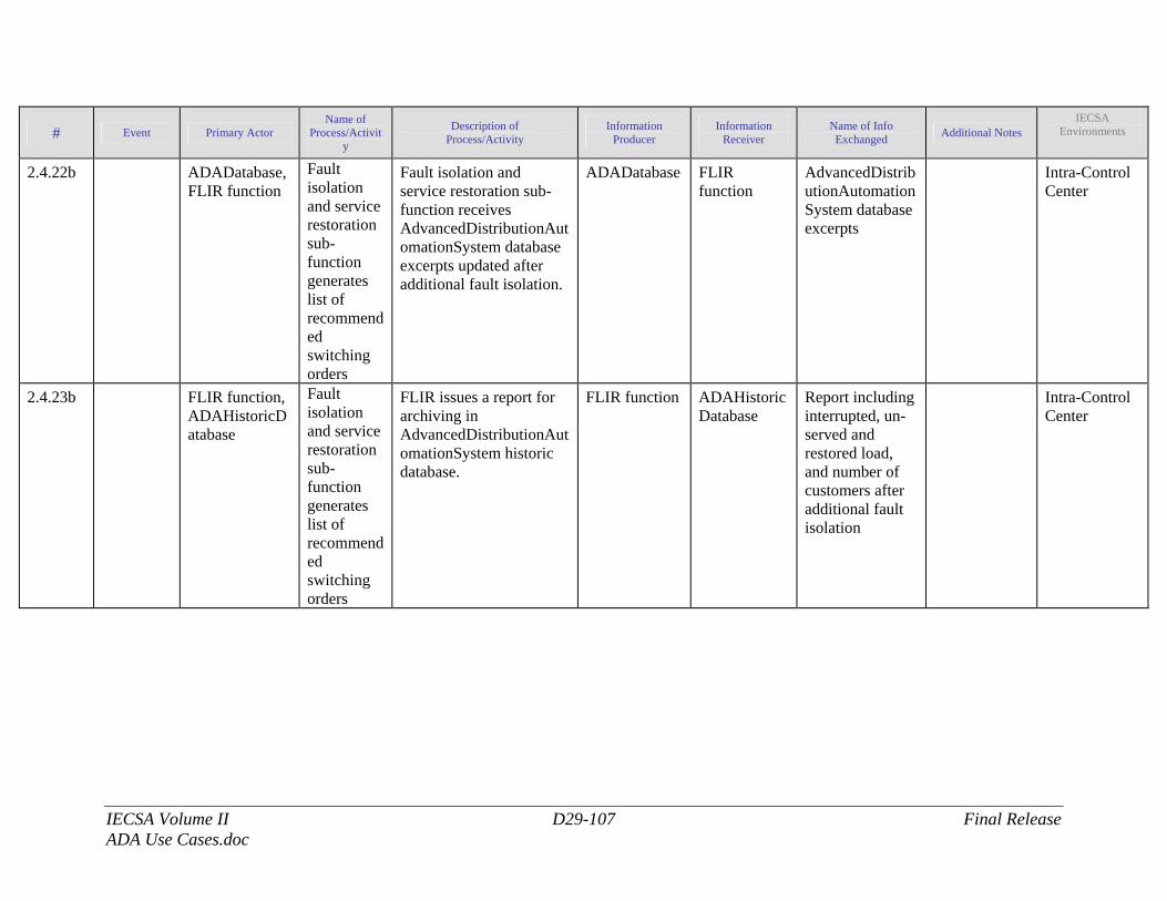
IECSA Volume II D29-107 Final Release ADA Use Cases.doc
# Event Primary Actor Name of
Process/Activity
Description of Process/Activity
Information Producer
Information Receiver
Name of Info Exchanged Additional Notes
IECSA Environments
2.4.22b ADADatabase, FLIR function
Fault isolation and service restoration sub-function generates list of recommended switching orders
Fault isolation and service restoration sub-function receives AdvancedDistributionAutomationSystem database excerpts updated after additional fault isolation.
ADADatabase FLIR function
AdvancedDistributionAutomationSystem database excerpts
Intra-Control Center
2.4.23b FLIR function, ADAHistoricDatabase
Fault isolation and service restoration sub-function generates list of recommended switching orders
FLIR issues a report for archiving in AdvancedDistributionAutomationSystem historic database.
FLIR function ADAHistoricDatabase
Report including interrupted, un-served and restored load, and number of customers after additional fault isolation
Intra-Control Center
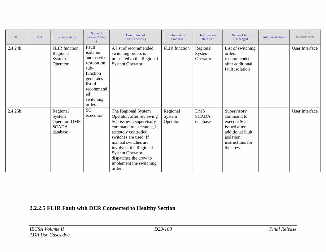
IECSA Volume II D29-108 Final Release ADA Use Cases.doc
# Event Primary Actor Name of
Process/Activity
Description of Process/Activity
Information Producer
Information Receiver
Name of Info Exchanged Additional Notes
IECSA Environments
2.4.24b FLIR function, Regional System Operator
Fault isolation and service restoration sub-function generates list of recommended switching orders
A list of recommended switching orders is presented to the Regional System Operator.
FLIR function Regional System Operator
List of switching orders recommended after additional fault isolation
User Interface
2.4.25b Regional System Operator, DMS SCADA database
SO execution
The Regional System Operator, after reviewing SO, issues a supervisory command to execute it, if remotely controlled switches are used. If manual switches are involved, the Regional System Operator dispatches the crew to implement the switching order.
Regional System Operator
DMS SCADA database
Supervisory command to execute SO issued after additional fault isolation; instructions for the crew.
User Interface
2.2.2.5 FLIR Fault with DER Connected to Healthy Section
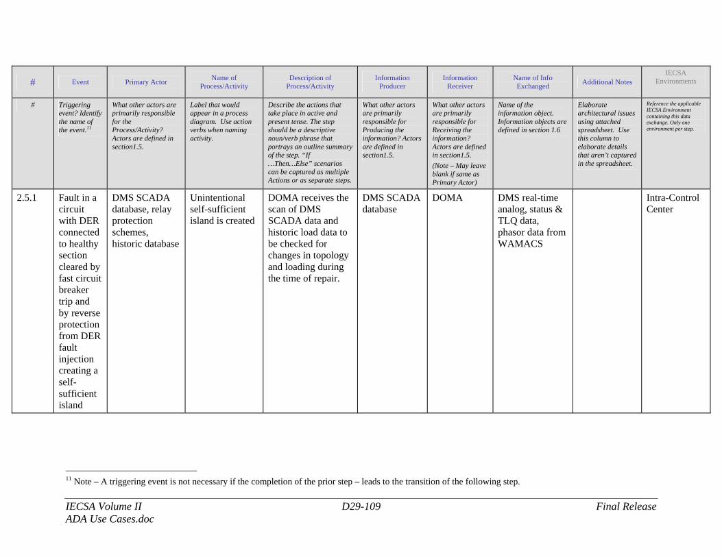
IECSA Volume II D29-109 Final Release ADA Use Cases.doc
# Event Primary Actor Name of Process/Activity
Description of Process/Activity
Information Producer
Information Receiver
Name of Info Exchanged Additional Notes
IECSA Environments
# Triggering event? Identify the name of the event.11
What other actors are primarily responsible for the Process/Activity? Actors are defined in section1.5.
Label that would appear in a process diagram. Use action verbs when naming activity.
Describe the actions that take place in active and present tense. The step should be a descriptive noun/verb phrase that portrays an outline summary of the step. “If …Then…Else” scenarios can be captured as multiple Actions or as separate steps.
What other actors are primarily responsible for Producing the information? Actors are defined in section1.5.
What other actors are primarily responsible for Receiving the information? Actors are defined in section1.5. (Note – May leave blank if same as Primary Actor)
Name of the information object. Information objects are defined in section 1.6
Elaborate architectural issues using attached spreadsheet. Use this column to elaborate details that aren’t captured in the spreadsheet.
Reference the applicable IECSA Environment containing this data exchange. Only one environment per step.
2.5.1 Fault in a circuit with DER connected to healthy section cleared by fast circuit breaker trip and by reverse protection from DER fault injection creating a self-sufficient island
DMS SCADA database, relay protection schemes, historic database
Unintentional self-sufficient island is created
DOMA receives the scan of DMS SCADA data and historic load data to be checked for changes in topology and loading during the time of repair.
DMS SCADA database
DOMA DMS real-time analog, status & TLQ data, phasor data from WAMACS
Intra-Control Center
11 Note – A triggering event is not necessary if the completion of the prior step – leads to the transition of the following step.
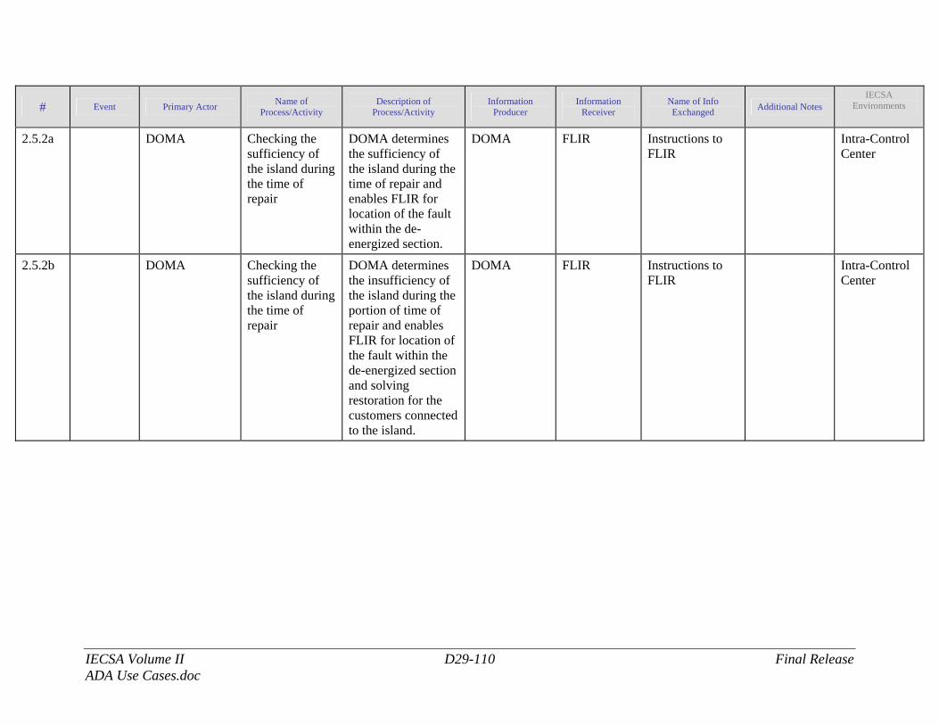
IECSA Volume II D29-110 Final Release ADA Use Cases.doc
# Event Primary Actor Name of Process/Activity
Description of Process/Activity
Information Producer
Information Receiver
Name of Info Exchanged Additional Notes
IECSA Environments
2.5.2a DOMA Checking the sufficiency of the island during the time of repair
DOMA determines the sufficiency of the island during the time of repair and enables FLIR for location of the fault within the de-energized section.
DOMA FLIR Instructions to FLIR
Intra-Control Center
2.5.2b DOMA Checking the sufficiency of the island during the time of repair
DOMA determines the insufficiency of the island during the portion of time of repair and enables FLIR for location of the fault within the de-energized section and solving restoration for the customers connected to the island.
DOMA FLIR Instructions to FLIR
Intra-Control Center
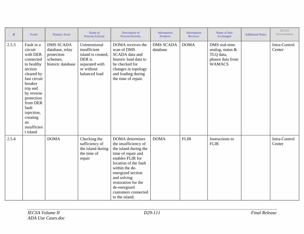
IECSA Volume II D29-111 Final Release ADA Use Cases.doc
# Event Primary Actor Name of Process/Activity
Description of Process/Activity
Information Producer
Information Receiver
Name of Info Exchanged Additional Notes
IECSA Environments
2.5.3 Fault in a circuit with DER connected to healthy section cleared by fast circuit breaker trip and by reverse protection from DER fault injection, creating an insufficient island
DMS SCADA database, relay protection schemes, historic database
Unintentional insufficient island is created, DER is separated with or without balanced load
DOMA receives the scan of DMS SCADA data and historic load data to be checked for changes in topology and loading during the time of repair.
DMS SCADA database
DOMA DMS real-time analog, status & TLQ data, phasor data from WAMACS
Intra-Control Center
2.5.4 DOMA Checking the sufficiency of the island during the time of repair
DOMA determines the insufficiency of the island during the time of repair and enables FLIR for location of the fault within the de-energized section and solving restoration for the de-energized customers connected to the island.
DOMA FLIR Instructions to FLIR
Intra-Control Center
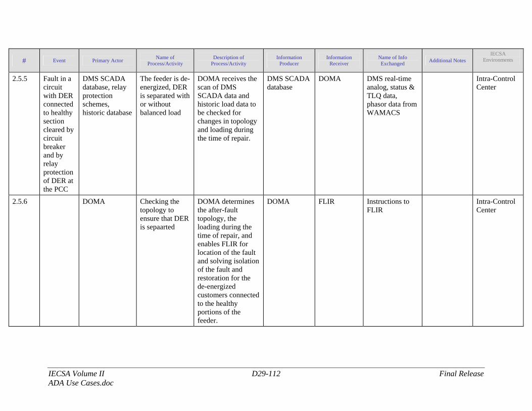
IECSA Volume II D29-112 Final Release ADA Use Cases.doc
# Event Primary Actor Name of Process/Activity
Description of Process/Activity
Information Producer
Information Receiver
Name of Info Exchanged Additional Notes
IECSA Environments
2.5.5 Fault in a circuit with DER connected to healthy section cleared by circuit breaker and by relay protection of DER at the PCC
DMS SCADA database, relay protection schemes, historic database
The feeder is de-energized, DER is separated with or without balanced load
DOMA receives the scan of DMS SCADA data and historic load data to be checked for changes in topology and loading during the time of repair.
DMS SCADA database
DOMA DMS real-time analog, status & TLQ data, phasor data from WAMACS
Intra-Control Center
2.5.6 DOMA Checking the topology to ensure that DER is sepaarted
DOMA determines the after-fault topology, the loading during the time of repair, and enables FLIR for location of the fault and solving isolation of the fault and restoration for the de-energized customers connected to the healthy portions of the feeder.
DOMA FLIR Instructions to FLIR
Intra-Control Center
IECSA Volume II D29-113 Final Release ADA Use Cases.doc
2.3.1 Post-conditions and Significant Results Actor/Activity Post-conditions Description and Results AdvancedDistributionAutomationSystem: Fault location function, Isolation and Restoration
Faulted section is identified. A solution for an optimal isolation of faulted portions of distribution feeder and restoration of services to healthy portions is provided to the operator; closed-loop execution of switching orders is available; outage time for the majority of customers is reduced to several minutes.
2.3.2 Diagrams
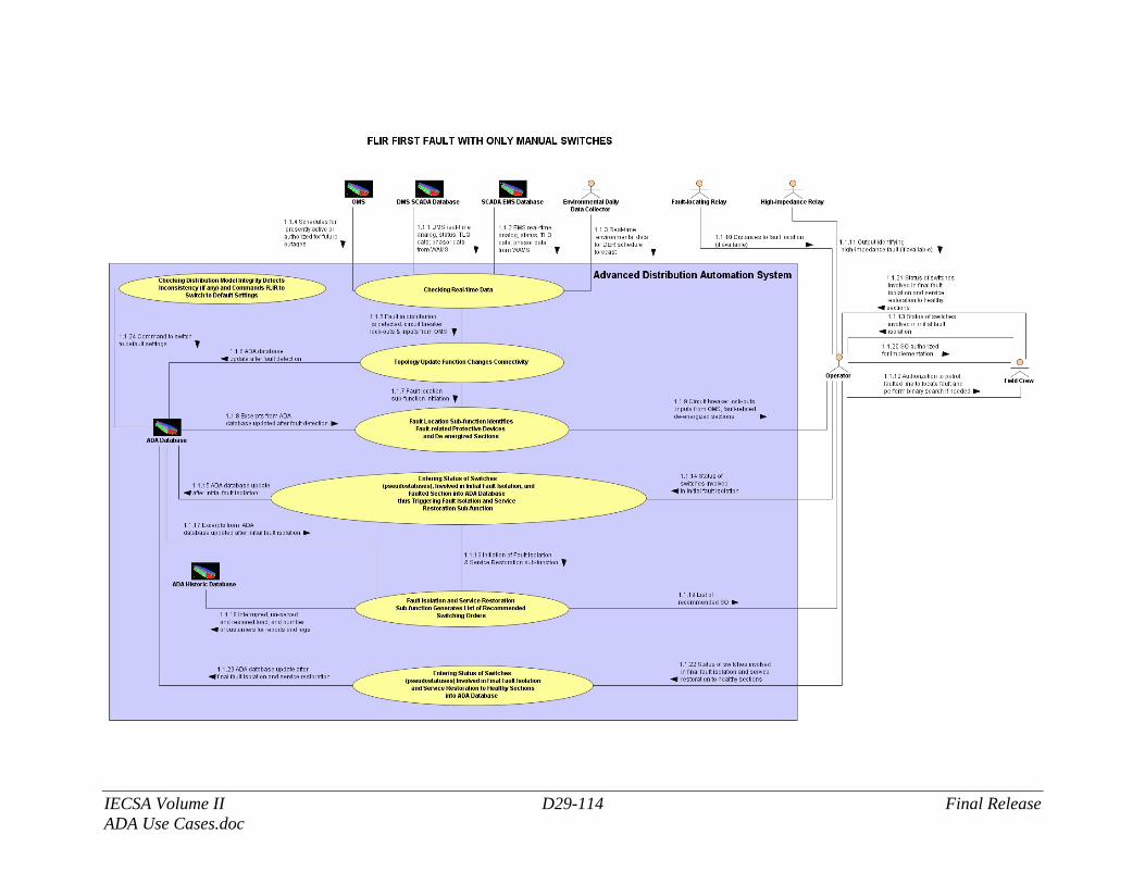
IECSA Volume II D29-114 Final Release ADA Use Cases.doc
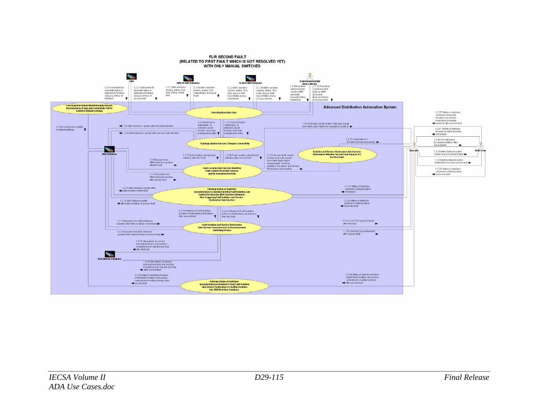
IECSA Volume II D29-115 Final Release ADA Use Cases.doc
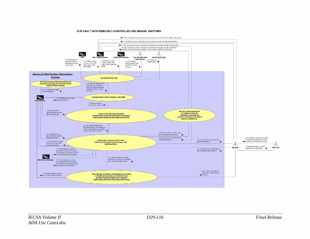
IECSA Volume II D29-116 Final Release ADA Use Cases.doc
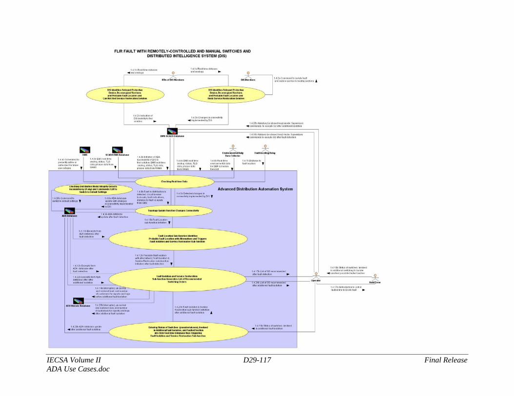
IECSA Volume II D29-117 Final Release ADA Use Cases.doc
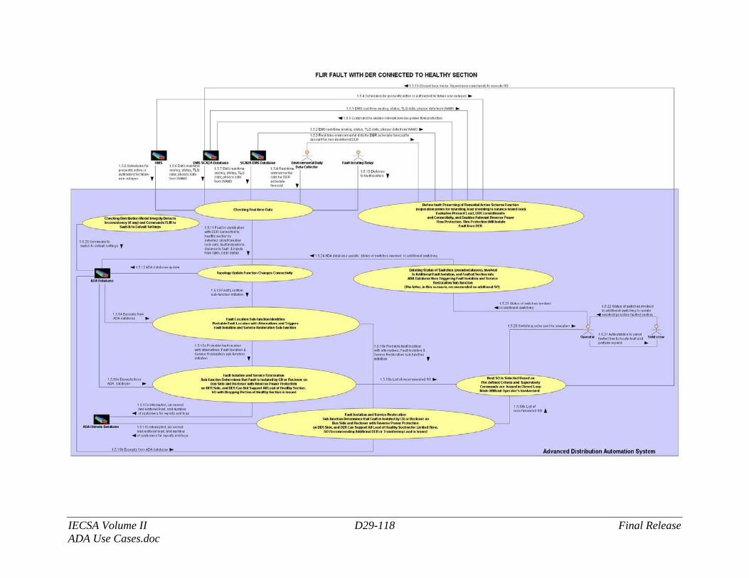
IECSA Volume II D29-118 Final Release ADA Use Cases.doc
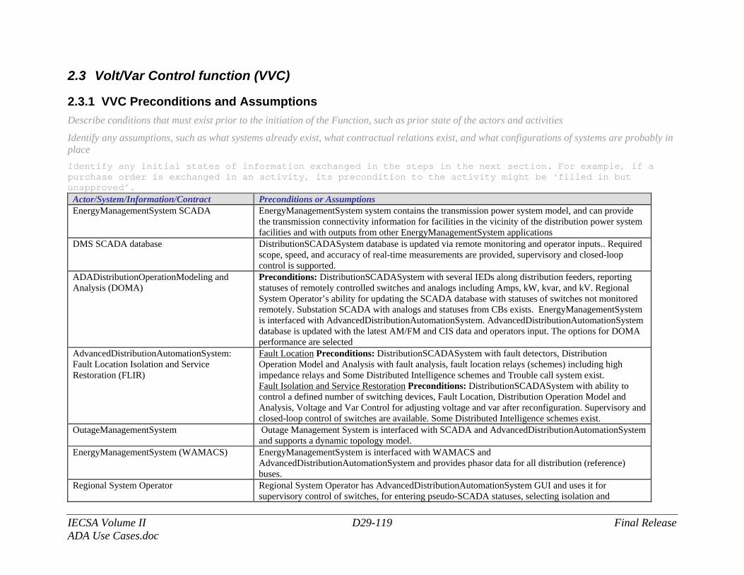
IECSA Volume II D29-119 Final Release ADA Use Cases.doc
2.3 Volt/Var Control function (VVC)
2.3.1 VVC Preconditions and Assumptions Describe conditions that must exist prior to the initiation of the Function, such as prior state of the actors and activities
Identify any assumptions, such as what systems already exist, what contractual relations exist, and what configurations of systems are probably in place Identify any initial states of information exchanged in the steps in the next section. For example, if a purchase order is exchanged in an activity, its precondition to the activity might be ‘filled in but unapproved’.
Actor/System/Information/Contract Preconditions or Assumptions EnergyManagementSystem SCADA EnergyManagementSystem system contains the transmission power system model, and can provide
the transmission connectivity information for facilities in the vicinity of the distribution power system facilities and with outputs from other EnergyManagementSystem applications
DMS SCADA database DistributionSCADASystem database is updated via remote monitoring and operator inputs.. Required scope, speed, and accuracy of real-time measurements are provided, supervisory and closed-loop control is supported.
ADADistributionOperationModeling and Analysis (DOMA)
Preconditions: DistributionSCADASystem with several IEDs along distribution feeders, reporting statuses of remotely controlled switches and analogs including Amps, kW, kvar, and kV. Regional System Operator’s ability for updating the SCADA database with statuses of switches not monitored remotely. Substation SCADA with analogs and statuses from CBs exists. EnergyManagementSystem is interfaced with AdvancedDistributionAutomationSystem. AdvancedDistributionAutomationSystem database is updated with the latest AM/FM and CIS data and operators input. The options for DOMA performance are selected
AdvancedDistributionAutomationSystem: Fault Location Isolation and Service Restoration (FLIR)
Fault Location Preconditions: DistributionSCADASystem with fault detectors, Distribution Operation Model and Analysis with fault analysis, fault location relays (schemes) including high impedance relays and Some Distributed Intelligence schemes and Trouble call system exist. Fault Isolation and Service Restoration Preconditions: DistributionSCADASystem with ability to control a defined number of switching devices, Fault Location, Distribution Operation Model and Analysis, Voltage and Var Control for adjusting voltage and var after reconfiguration. Supervisory and closed-loop control of switches are available. Some Distributed Intelligence schemes exist.
OutageManagementSystem Outage Management System is interfaced with SCADA and AdvancedDistributionAutomationSystem and supports a dynamic topology model.
EnergyManagementSystem (WAMACS) EnergyManagementSystem is interfaced with WAMACS and AdvancedDistributionAutomationSystem and provides phasor data for all distribution (reference) buses.
Regional System Operator Regional System Operator has AdvancedDistributionAutomationSystem GUI and uses it for supervisory control of switches, for entering pseudo-SCADA statuses, selecting isolation and
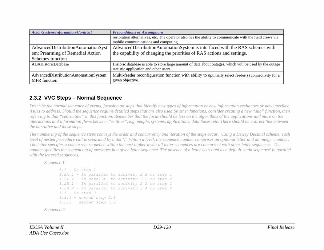
IECSA Volume II D29-120 Final Release ADA Use Cases.doc
Actor/System/Information/Contract Preconditions or Assumptions restoration alternatives, etc. The operator also has the ability to communicate with the field crews via mobile communications and computing.
AdvancedDistributionAutomationSystem: Prearming of Remedial Action Schemes function
AdvancedDistributionAutomationSystem is interfaced with the RAS schemes with the capability of changing the priorities of RAS actions and settings.
ADAHistoricDatabase Historic database is able to store large amount of data about outages, which will be used by the outage statistic application and other users.
AdvancedDistributionAutomationSystem: MFR function
Multi-feeder reconfiguration function with ability to optimally select feeder(s) connectivity for a given objective.
2.3.2 VVC Steps – Normal Sequence Describe the normal sequence of events, focusing on steps that identify new types of information or new information exchanges or new interface issues to address. Should the sequence require detailed steps that are also used by other functions, consider creating a new “sub” function, then referring to that “subroutine” in this function. Remember that the focus should be less on the algorithms of the applications and more on the interactions and information flows between “entities”, e.g. people, systems, applications, data bases, etc. There should be a direct link between the narrative and these steps.
The numbering of the sequence steps conveys the order and concurrency and iteration of the steps occur. Using a Dewey Decimal scheme, each level of nested procedure call is separated by a dot ‘.’. Within a level, the sequence number comprises an optional letter and an integer number. The letter specifies a concurrent sequence within the next higher level; all letter sequences are concurrent with other letter sequences. The number specifies the sequencing of messages in a given letter sequence. The absence of a letter is treated as a default 'main sequence' in parallel with the lettered sequences.
Sequence 1: 1.1 - Do step 1 1.2A.1 - In parallel to activity 2 B do step 1
1.2A.2 - In parallel to activity 2 B do step 2 1.2B.1 - In parallel to activity 2 A do step 1 1.2B.2 - In parallel to activity 2 A do step 2 1.3 - Do step 3
1.3.1 - nested step 3.1 1.3.2 - nested step 3.2
Sequence 2:
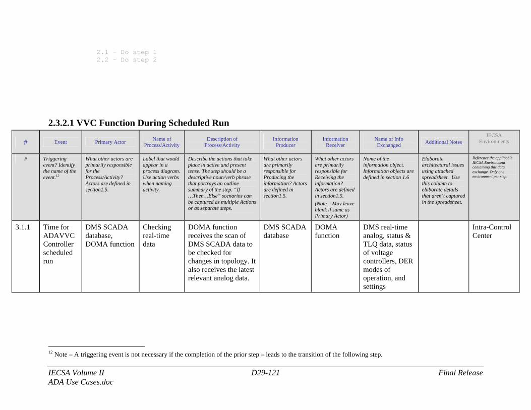
IECSA Volume II D29-121 Final Release ADA Use Cases.doc
2.1 - Do step 1 2.2 – Do step 2
2.3.2.1 VVC Function During Scheduled Run
# Event Primary Actor Name of Process/Activity
Description of Process/Activity
Information Producer
Information Receiver
Name of Info Exchanged Additional Notes
IECSA Environments
# Triggering event? Identify the name of the event.12
What other actors are primarily responsible for the Process/Activity? Actors are defined in section1.5.
Label that would appear in a process diagram. Use action verbs when naming activity.
Describe the actions that take place in active and present tense. The step should be a descriptive noun/verb phrase that portrays an outline summary of the step. “If …Then…Else” scenarios can be captured as multiple Actions or as separate steps.
What other actors are primarily responsible for Producing the information? Actors are defined in section1.5.
What other actors are primarily responsible for Receiving the information? Actors are defined in section1.5. (Note – May leave blank if same as Primary Actor)
Name of the information object. Information objects are defined in section 1.6
Elaborate architectural issues using attached spreadsheet. Use this column to elaborate details that aren’t captured in the spreadsheet.
Reference the applicable IECSA Environment containing this data exchange. Only one environment per step.
3.1.1 Time for ADAVVCController scheduled run
DMS SCADA database, DOMA function
Checking real-time data
DOMA function receives the scan of DMS SCADA data to be checked for changes in topology. It also receives the latest relevant analog data.
DMS SCADA database
DOMA function
DMS real-time analog, status & TLQ data, status of voltage controllers, DER modes of operation, and settings
Intra-Control Center
12 Note – A triggering event is not necessary if the completion of the prior step – leads to the transition of the following step.
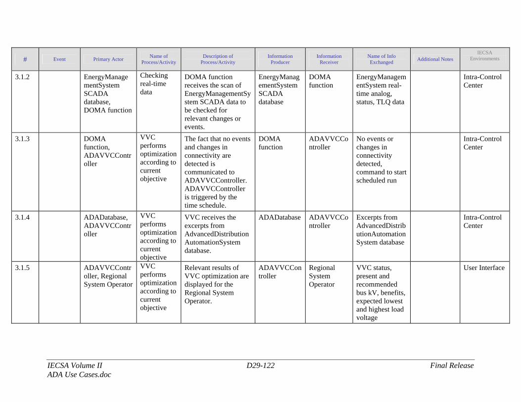
IECSA Volume II D29-122 Final Release ADA Use Cases.doc
# Event Primary Actor Name of Process/Activity
Description of Process/Activity
Information Producer
Information Receiver
Name of Info Exchanged Additional Notes
IECSA Environments
3.1.2 EnergyManagementSystem SCADA database, DOMA function
Checking real-time data
DOMA function receives the scan of EnergyManagementSystem SCADA data to be checked for relevant changes or events.
EnergyManagementSystem SCADA database
DOMA function
EnergyManagementSystem real-time analog, status, TLQ data
Intra-Control Center
3.1.3 DOMA function, ADAVVCController
VVC performs optimization according to current objective
The fact that no events and changes in connectivity are detected is communicated to ADAVVCController. ADAVVCController is triggered by the time schedule.
DOMA function
ADAVVCController
No events or changes in connectivity detected, command to start scheduled run
Intra-Control Center
3.1.4 ADADatabase, ADAVVCController
VVC performs optimization according to current objective
VVC receives the excerpts from AdvancedDistributionAutomationSystem database.
ADADatabase ADAVVCController
Excerpts from AdvancedDistributionAutomationSystem database
Intra-Control Center
3.1.5 ADAVVCController, Regional System Operator
VVC performs optimization according to current objective
Relevant results of VVC optimization are displayed for the Regional System Operator.
ADAVVCController
Regional System Operator
VVC status, present and recommended bus kV, benefits, expected lowest and highest load voltage
User Interface
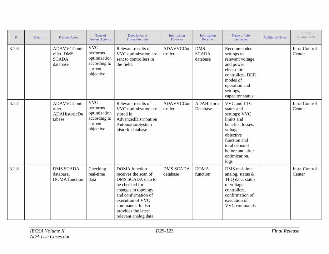
IECSA Volume II D29-123 Final Release ADA Use Cases.doc
# Event Primary Actor Name of Process/Activity
Description of Process/Activity
Information Producer
Information Receiver
Name of Info Exchanged Additional Notes
IECSA Environments
3.1.6 ADAVVCController, DMS SCADA database
VVC performs optimization according to current objective
Relevant results of VVC optimization are sent to controllers in the field.
ADAVVCController
DMS SCADA database
Recommended settings to relevant voltage and power electronic controllers, DER modes of operation and settings, capacitor status
Intra-Control Center
3.1.7 ADAVVCController, ADAHistoricDatabase
VVC performs optimization according to current objective
Relevant results of VVC optimization are stored in AdvancedDistributionAutomationSystem historic database.
ADAVVCController
ADAHistoricDatabase
VVC and LTC states and settings; VVC limits and benefits; losses, voltage, objective function and total demand before and after optimization, logs
Intra-Control Center
3.1.8 DMS SCADA database, DOMA function
Checking real-time data
DOMA function receives the scan of DMS SCADA data to be checked for changes in topology and confirmation of execution of VVC commands. It also provides the latest relevant analog data.
DMS SCADA database
DOMA function
DMS real-time analog, status & TLQ data, status of voltage controllers, confirmation of execution of VVC commands
Intra-Control Center
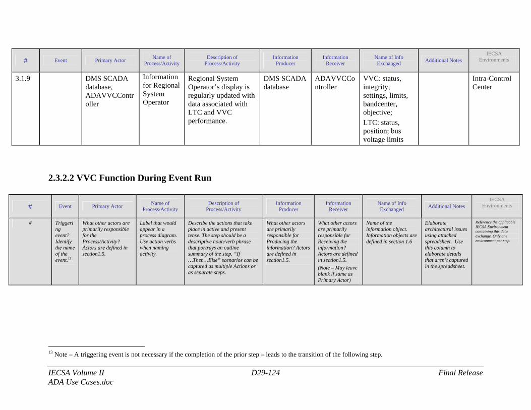
IECSA Volume II D29-124 Final Release ADA Use Cases.doc
# Event Primary Actor Name of Process/Activity
Description of Process/Activity
Information Producer
Information Receiver
Name of Info Exchanged Additional Notes
IECSA Environments
3.1.9 DMS SCADA database, ADAVVCController
Information for Regional System Operator
Regional System Operator’s display is regularly updated with data associated with LTC and VVC performance.
DMS SCADA database
ADAVVCController
VVC: status, integrity, settings, limits, bandcenter, objective; LTC: status, position; bus voltage limits
Intra-Control Center
2.3.2.2 VVC Function During Event Run
# Event Primary Actor Name of Process/Activity
Description of Process/Activity
Information Producer
Information Receiver
Name of Info Exchanged Additional Notes
IECSA Environments
# Triggering event? Identify the name of the event.13
What other actors are primarily responsible for the Process/Activity? Actors are defined in section1.5.
Label that would appear in a process diagram. Use action verbs when naming activity.
Describe the actions that take place in active and present tense. The step should be a descriptive noun/verb phrase that portrays an outline summary of the step. “If …Then…Else” scenarios can be captured as multiple Actions or as separate steps.
What other actors are primarily responsible for Producing the information? Actors are defined in section1.5.
What other actors are primarily responsible for Receiving the information? Actors are defined in section1.5. (Note – May leave blank if same as Primary Actor)
Name of the information object. Information objects are defined in section 1.6
Elaborate architectural issues using attached spreadsheet. Use this column to elaborate details that aren’t captured in the spreadsheet.
Reference the applicable IECSA Environment containing this data exchange. Only one environment per step.
13 Note – A triggering event is not necessary if the completion of the prior step – leads to the transition of the following step.
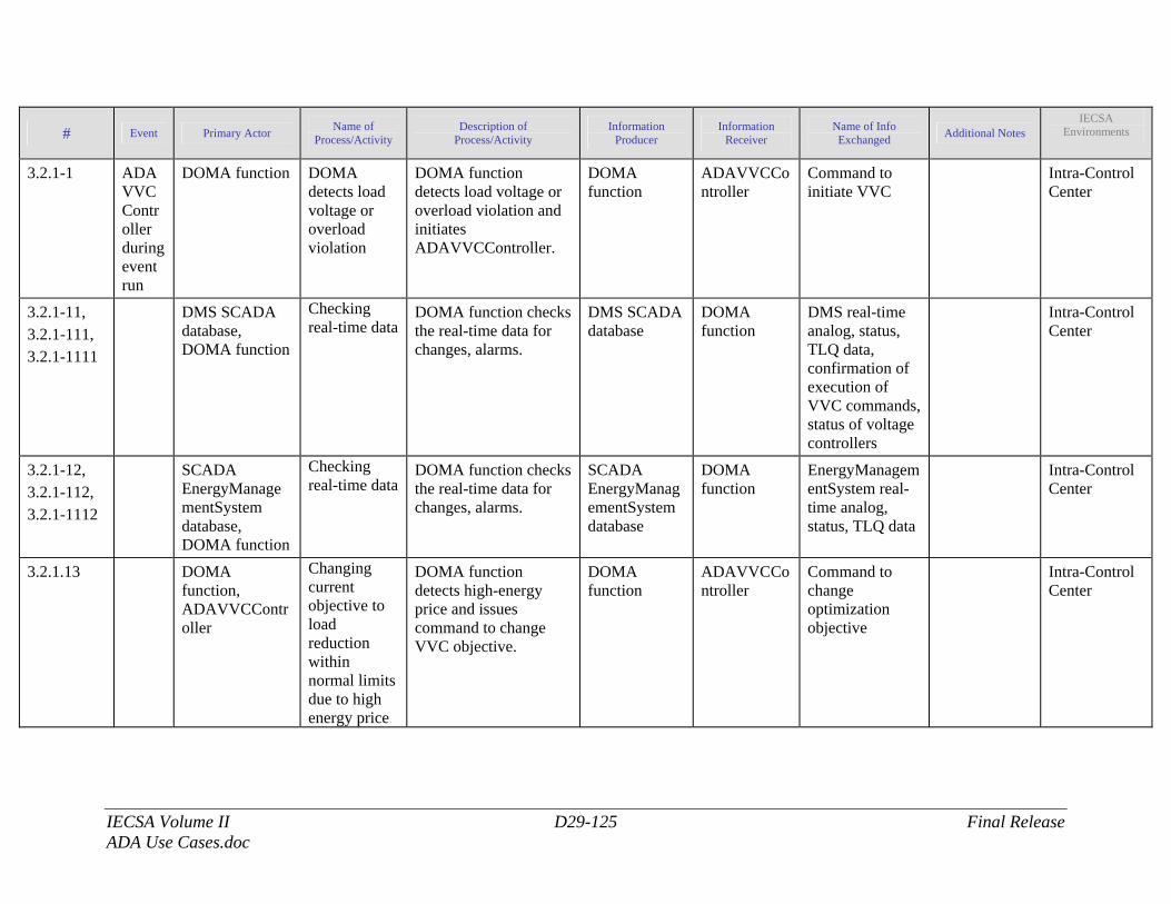
IECSA Volume II D29-125 Final Release ADA Use Cases.doc
# Event Primary Actor Name of Process/Activity
Description of Process/Activity
Information Producer
Information Receiver
Name of Info Exchanged Additional Notes
IECSA Environments
3.2.1-1 ADAVVCController during event run
DOMA function DOMA detects load voltage or overload violation
DOMA function detects load voltage or overload violation and initiates ADAVVCController.
DOMA function
ADAVVCController
Command to initiate VVC
Intra-Control Center
3.2.1-11, 3.2.1-111, 3.2.1-1111
DMS SCADA database, DOMA function
Checking real-time data
DOMA function checks the real-time data for changes, alarms.
DMS SCADA database
DOMA function
DMS real-time analog, status, TLQ data, confirmation of execution of VVC commands, status of voltage controllers
Intra-Control Center
3.2.1-12, 3.2.1-112, 3.2.1-1112
SCADA EnergyManagementSystem database, DOMA function
Checking real-time data
DOMA function checks the real-time data for changes, alarms.
SCADA EnergyManagementSystem database
DOMA function
EnergyManagementSystem real-time analog, status, TLQ data
Intra-Control Center
3.2.1.13 DOMA function, ADAVVCController
Changing current objective to load reduction within normal limits due to high energy price
DOMA function detects high-energy price and issues command to change VVC objective.
DOMA function
ADAVVCController
Command to change optimization objective
Intra-Control Center
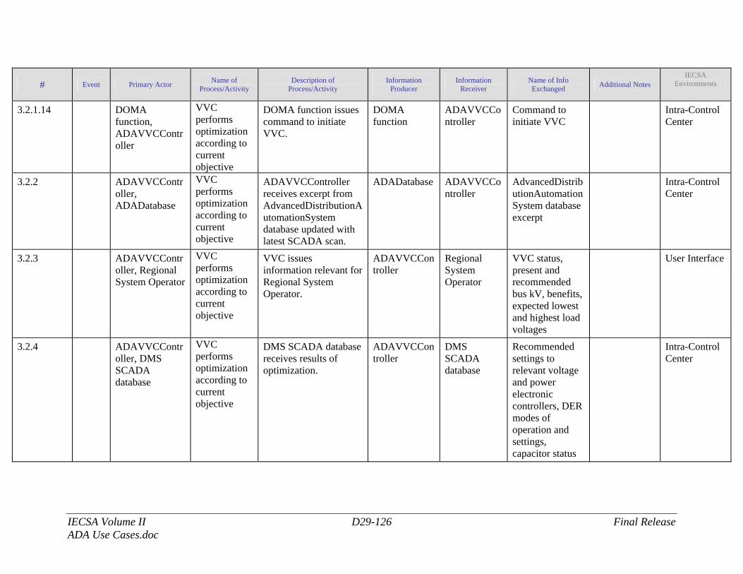
IECSA Volume II D29-126 Final Release ADA Use Cases.doc
# Event Primary Actor Name of Process/Activity
Description of Process/Activity
Information Producer
Information Receiver
Name of Info Exchanged Additional Notes
IECSA Environments
3.2.1.14 DOMA function, ADAVVCController
VVC performs optimization according to current objective
DOMA function issues command to initiate VVC.
DOMA function
ADAVVCController
Command to initiate VVC
Intra-Control Center
3.2.2 ADAVVCController, ADADatabase
VVC performs optimization according to current objective
ADAVVCController receives excerpt from AdvancedDistributionAutomationSystem database updated with latest SCADA scan.
ADADatabase ADAVVCController
AdvancedDistributionAutomationSystem database excerpt
Intra-Control Center
3.2.3 ADAVVCController, Regional System Operator
VVC performs optimization according to current objective
VVC issues information relevant for Regional System Operator.
ADAVVCController
Regional System Operator
VVC status, present and recommended bus kV, benefits, expected lowest and highest load voltages
User Interface
3.2.4 ADAVVCController, DMS SCADA database
VVC performs optimization according to current objective
DMS SCADA database receives results of optimization.
ADAVVCController
DMS SCADA database
Recommended settings to relevant voltage and power electronic controllers, DER modes of operation and settings, capacitor status
Intra-Control Center
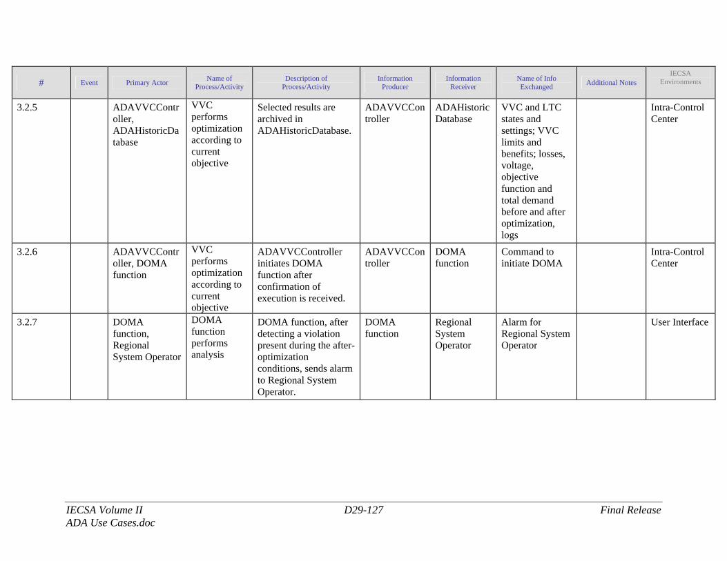
IECSA Volume II D29-127 Final Release ADA Use Cases.doc
# Event Primary Actor Name of Process/Activity
Description of Process/Activity
Information Producer
Information Receiver
Name of Info Exchanged Additional Notes
IECSA Environments
3.2.5 ADAVVCController, ADAHistoricDatabase
VVC performs optimization according to current objective
Selected results are archived in ADAHistoricDatabase.
ADAVVCController
ADAHistoricDatabase
VVC and LTC states and settings; VVC limits and benefits; losses, voltage, objective function and total demand before and after optimization, logs
Intra-Control Center
3.2.6 ADAVVCController, DOMA function
VVC performs optimization according to current objective
ADAVVCController initiates DOMA function after confirmation of execution is received.
ADAVVCController
DOMA function
Command to initiate DOMA
Intra-Control Center
3.2.7 DOMA function, Regional System Operator
DOMA function performs analysis
DOMA function, after detecting a violation present during the after-optimization conditions, sends alarm to Regional System Operator.
DOMA function
Regional System Operator
Alarm for Regional System Operator
User Interface
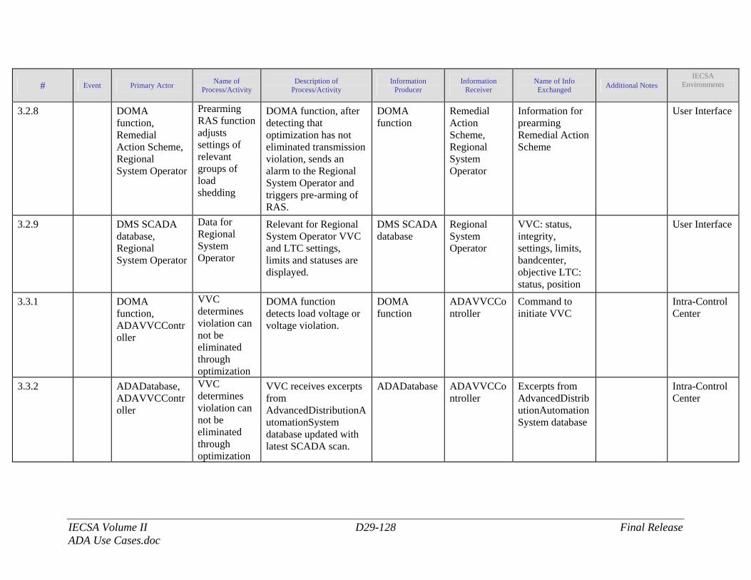
IECSA Volume II D29-128 Final Release ADA Use Cases.doc
# Event Primary Actor Name of Process/Activity
Description of Process/Activity
Information Producer
Information Receiver
Name of Info Exchanged Additional Notes
IECSA Environments
3.2.8 DOMA function, Remedial Action Scheme, Regional System Operator
Prearming RAS function adjusts settings of relevant groups of load shedding
DOMA function, after detecting that optimization has not eliminated transmission violation, sends an alarm to the Regional System Operator and triggers pre-arming of RAS.
DOMA function
Remedial Action Scheme, Regional System Operator
Information for prearming Remedial Action Scheme
User Interface
3.2.9 DMS SCADA database, Regional System Operator
Data for Regional System Operator
Relevant for Regional System Operator VVC and LTC settings, limits and statuses are displayed.
DMS SCADA database
Regional System Operator
VVC: status, integrity, settings, limits, bandcenter, objective LTC: status, position
User Interface
3.3.1 DOMA function, ADAVVCController
VVC determines violation can not be eliminated through optimization
DOMA function detects load voltage or voltage violation.
DOMA function
ADAVVCController
Command to initiate VVC
Intra-Control Center
3.3.2 ADADatabase, ADAVVCController
VVC determines violation can not be eliminated through optimization
VVC receives excerpts from AdvancedDistributionAutomationSystem database updated with latest SCADA scan.
ADADatabase ADAVVCController
Excerpts from AdvancedDistributionAutomationSystem database
Intra-Control Center
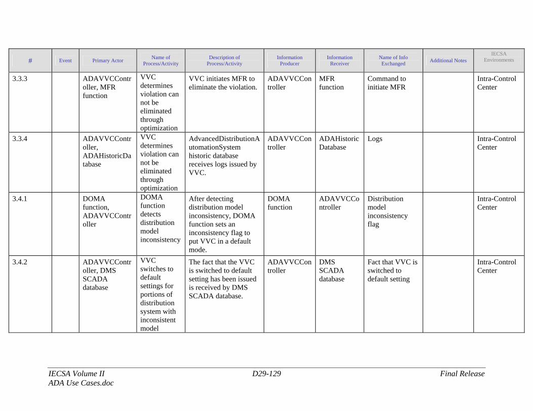
IECSA Volume II D29-129 Final Release ADA Use Cases.doc
# Event Primary Actor Name of Process/Activity
Description of Process/Activity
Information Producer
Information Receiver
Name of Info Exchanged Additional Notes
IECSA Environments
3.3.3 ADAVVCController, MFR function
VVC determines violation can not be eliminated through optimization
VVC initiates MFR to eliminate the violation.
ADAVVCController
MFR function
Command to initiate MFR
Intra-Control Center
3.3.4 ADAVVCController, ADAHistoricDatabase
VVC determines violation can not be eliminated through optimization
AdvancedDistributionAutomationSystem historic database receives logs issued by VVC.
ADAVVCController
ADAHistoricDatabase
Logs Intra-Control Center
3.4.1 DOMA function, ADAVVCController
DOMA function detects distribution model inconsistency
After detecting distribution model inconsistency, DOMA function sets an inconsistency flag to put VVC in a default mode.
DOMA function
ADAVVCController
Distribution model inconsistency flag
Intra-Control Center
3.4.2 ADAVVCController, DMS SCADA database
VVC switches to default settings for portions of distribution system with inconsistent model
The fact that the VVC is switched to default setting has been issued is received by DMS SCADA database.
ADAVVCController
DMS SCADA database
Fact that VVC is switched to default setting
Intra-Control Center
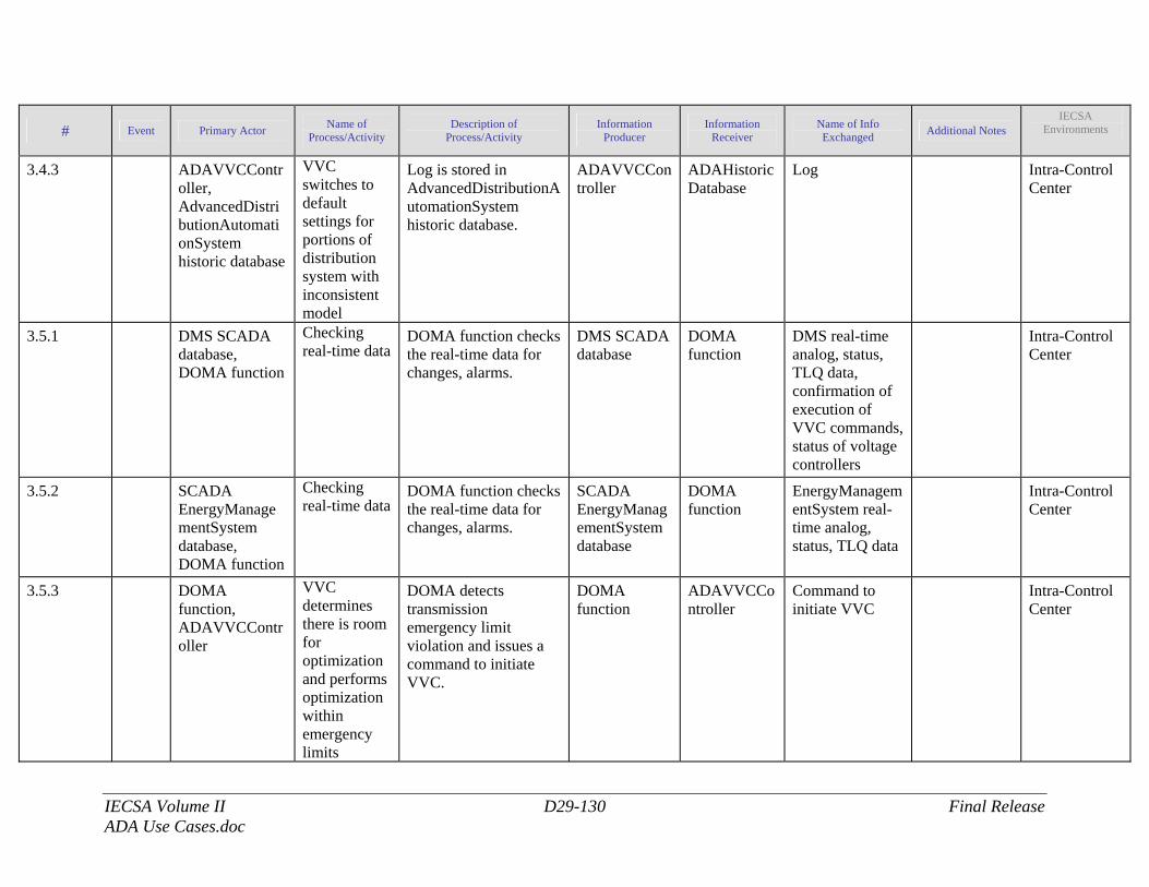
IECSA Volume II D29-130 Final Release ADA Use Cases.doc
# Event Primary Actor Name of Process/Activity
Description of Process/Activity
Information Producer
Information Receiver
Name of Info Exchanged Additional Notes
IECSA Environments
3.4.3 ADAVVCController, AdvancedDistributionAutomationSystem historic database
VVC switches to default settings for portions of distribution system with inconsistent model
Log is stored in AdvancedDistributionAutomationSystem historic database.
ADAVVCController
ADAHistoricDatabase
Log Intra-Control Center
3.5.1 DMS SCADA database, DOMA function
Checking real-time data
DOMA function checks the real-time data for changes, alarms.
DMS SCADA database
DOMA function
DMS real-time analog, status, TLQ data, confirmation of execution of VVC commands, status of voltage controllers
Intra-Control Center
3.5.2 SCADA EnergyManagementSystem database, DOMA function
Checking real-time data
DOMA function checks the real-time data for changes, alarms.
SCADA EnergyManagementSystem database
DOMA function
EnergyManagementSystem real-time analog, status, TLQ data
Intra-Control Center
3.5.3 DOMA function, ADAVVCController
VVC determines there is room for optimization and performs optimization within emergency limits
DOMA detects transmission emergency limit violation and issues a command to initiate VVC.
DOMA function
ADAVVCController
Command to initiate VVC
Intra-Control Center
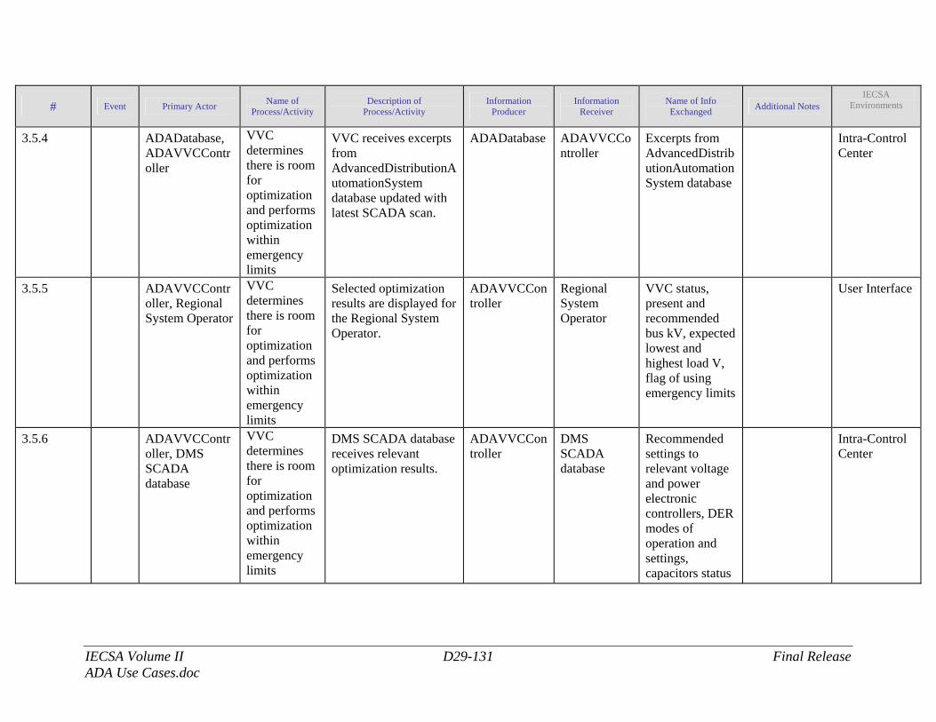
IECSA Volume II D29-131 Final Release ADA Use Cases.doc
# Event Primary Actor Name of Process/Activity
Description of Process/Activity
Information Producer
Information Receiver
Name of Info Exchanged Additional Notes
IECSA Environments
3.5.4 ADADatabase, ADAVVCController
VVC determines there is room for optimization and performs optimization within emergency limits
VVC receives excerpts from AdvancedDistributionAutomationSystem database updated with latest SCADA scan.
ADADatabase ADAVVCController
Excerpts from AdvancedDistributionAutomationSystem database
Intra-Control Center
3.5.5 ADAVVCController, Regional System Operator
VVC determines there is room for optimization and performs optimization within emergency limits
Selected optimization results are displayed for the Regional System Operator.
ADAVVCController
Regional System Operator
VVC status, present and recommended bus kV, expected lowest and highest load V, flag of using emergency limits
User Interface
3.5.6 ADAVVCController, DMS SCADA database
VVC determines there is room for optimization and performs optimization within emergency limits
DMS SCADA database receives relevant optimization results.
ADAVVCController
DMS SCADA database
Recommended settings to relevant voltage and power electronic controllers, DER modes of operation and settings, capacitors status
Intra-Control Center
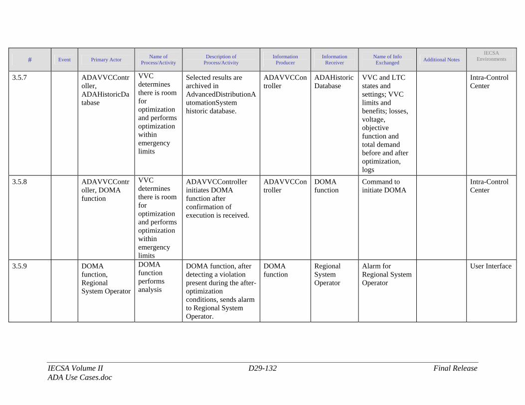
IECSA Volume II D29-132 Final Release ADA Use Cases.doc
# Event Primary Actor Name of Process/Activity
Description of Process/Activity
Information Producer
Information Receiver
Name of Info Exchanged Additional Notes
IECSA Environments
3.5.7 ADAVVCController, ADAHistoricDatabase
VVC determines there is room for optimization and performs optimization within emergency limits
Selected results are archived in AdvancedDistributionAutomationSystem historic database.
ADAVVCController
ADAHistoricDatabase
VVC and LTC states and settings; VVC limits and benefits; losses, voltage, objective function and total demand before and after optimization, logs
Intra-Control Center
3.5.8 ADAVVCController, DOMA function
VVC determines there is room for optimization and performs optimization within emergency limits
ADAVVCController initiates DOMA function after confirmation of execution is received.
ADAVVCController
DOMA function
Command to initiate DOMA
Intra-Control Center
3.5.9 DOMA function, Regional System Operator
DOMA function performs analysis
DOMA function, after detecting a violation present during the after-optimization conditions, sends alarm to Regional System Operator.
DOMA function
Regional System Operator
Alarm for Regional System Operator
User Interface
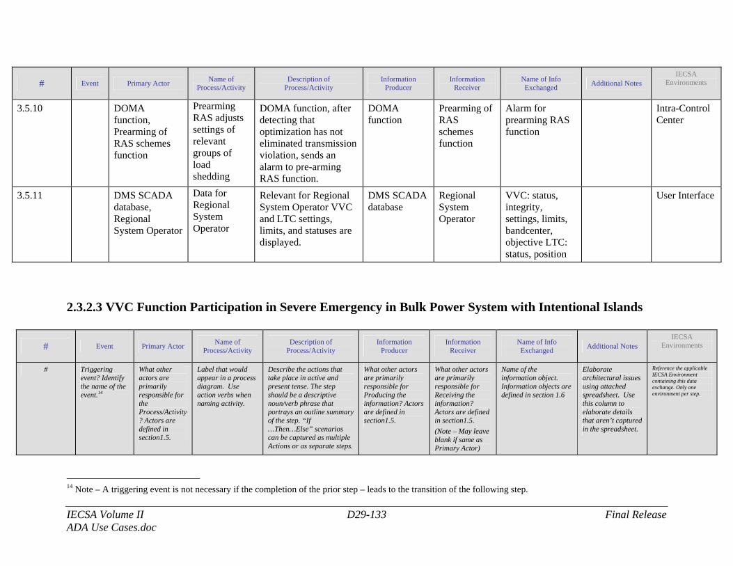
IECSA Volume II D29-133 Final Release ADA Use Cases.doc
# Event Primary Actor Name of Process/Activity
Description of Process/Activity
Information Producer
Information Receiver
Name of Info Exchanged Additional Notes
IECSA Environments
3.5.10 DOMA function, Prearming of RAS schemes function
Prearming RAS adjusts settings of relevant groups of load shedding
DOMA function, after detecting that optimization has not eliminated transmission violation, sends an alarm to pre-arming RAS function.
DOMA function
Prearming of RAS schemes function
Alarm for prearming RAS function
Intra-Control Center
3.5.11 DMS SCADA database, Regional System Operator
Data for Regional System Operator
Relevant for Regional System Operator VVC and LTC settings, limits, and statuses are displayed.
DMS SCADA database
Regional System Operator
VVC: status, integrity, settings, limits, bandcenter, objective LTC: status, position
User Interface
2.3.2.3 VVC Function Participation in Severe Emergency in Bulk Power System with Intentional Islands
# Event Primary Actor Name of Process/Activity
Description of Process/Activity
Information Producer
Information Receiver
Name of Info Exchanged Additional Notes
IECSA Environments
# Triggering event? Identify the name of the event.14
What other actors are primarily responsible for the Process/Activity? Actors are defined in section1.5.
Label that would appear in a process diagram. Use action verbs when naming activity.
Describe the actions that take place in active and present tense. The step should be a descriptive noun/verb phrase that portrays an outline summary of the step. “If …Then…Else” scenarios can be captured as multiple Actions or as separate steps.
What other actors are primarily responsible for Producing the information? Actors are defined in section1.5.
What other actors are primarily responsible for Receiving the information? Actors are defined in section1.5. (Note – May leave blank if same as Primary Actor)
Name of the information object. Information objects are defined in section 1.6
Elaborate architectural issues using attached spreadsheet. Use this column to elaborate details that aren’t captured in the spreadsheet.
Reference the applicable IECSA Environment containing this data exchange. Only one environment per step.
14 Note – A triggering event is not necessary if the completion of the prior step – leads to the transition of the following step.
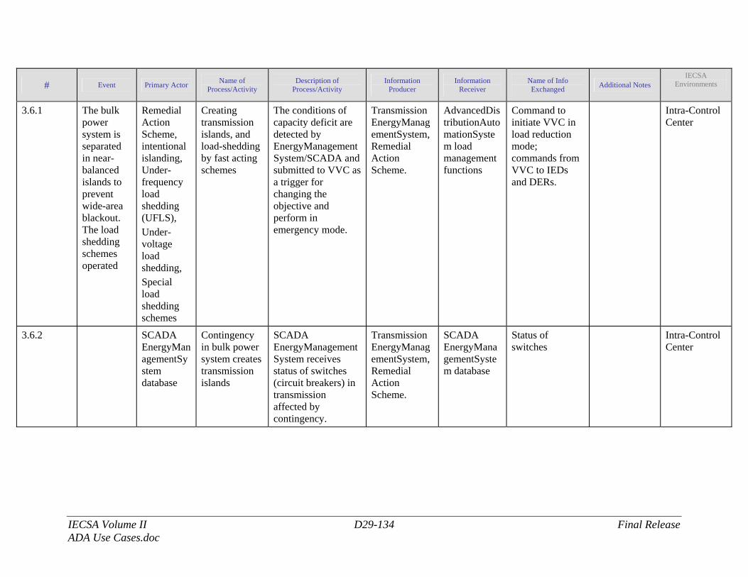
IECSA Volume II D29-134 Final Release ADA Use Cases.doc
# Event Primary Actor Name of Process/Activity
Description of Process/Activity
Information Producer
Information Receiver
Name of Info Exchanged Additional Notes
IECSA Environments
3.6.1 The bulk power system is separated in near-balanced islands to prevent wide-area blackout. The load shedding schemes operated
Remedial Action Scheme, intentional islanding, Under-frequency load shedding (UFLS), Under-voltage load shedding, Special load shedding schemes
Creating transmission islands, and load-shedding by fast acting schemes
The conditions of capacity deficit are detected by EnergyManagementSystem/SCADA and submitted to VVC as a trigger for changing the objective and perform in emergency mode.
Transmission EnergyManagementSystem, Remedial Action Scheme.
AdvancedDistributionAutomationSystem load management functions
Command to initiate VVC in load reduction mode; commands from VVC to IEDs and DERs.
Intra-Control Center
3.6.2 SCADA EnergyManagementSystem database
Contingency in bulk power system creates transmission islands
SCADA EnergyManagementSystem receives status of switches (circuit breakers) in transmission affected by contingency.
Transmission EnergyManagementSystem, Remedial Action Scheme.
SCADA EnergyManagementSystem database
Status of switches
Intra-Control Center
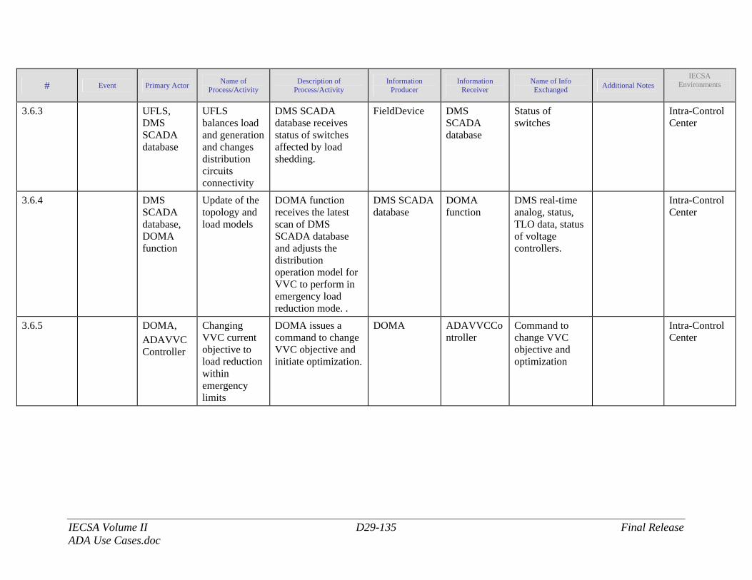
IECSA Volume II D29-135 Final Release ADA Use Cases.doc
# Event Primary Actor Name of Process/Activity
Description of Process/Activity
Information Producer
Information Receiver
Name of Info Exchanged Additional Notes
IECSA Environments
3.6.3 UFLS, DMS SCADA database
UFLS balances load and generation and changes distribution circuits connectivity
DMS SCADA database receives status of switches affected by load shedding.
FieldDevice DMS SCADA database
Status of switches
Intra-Control Center
3.6.4 DMS SCADA database, DOMA function
Update of the topology and load models
DOMA function receives the latest scan of DMS SCADA database and adjusts the distribution operation model for VVC to perform in emergency load reduction mode. .
DMS SCADA database
DOMA function
DMS real-time analog, status, TLO data, status of voltage controllers.
Intra-Control Center
3.6.5 DOMA, ADAVVCController
Changing VVC current objective to load reduction within emergency limits
DOMA issues a command to change VVC objective and initiate optimization.
DOMA ADAVVCController
Command to change VVC objective and optimization
Intra-Control Center
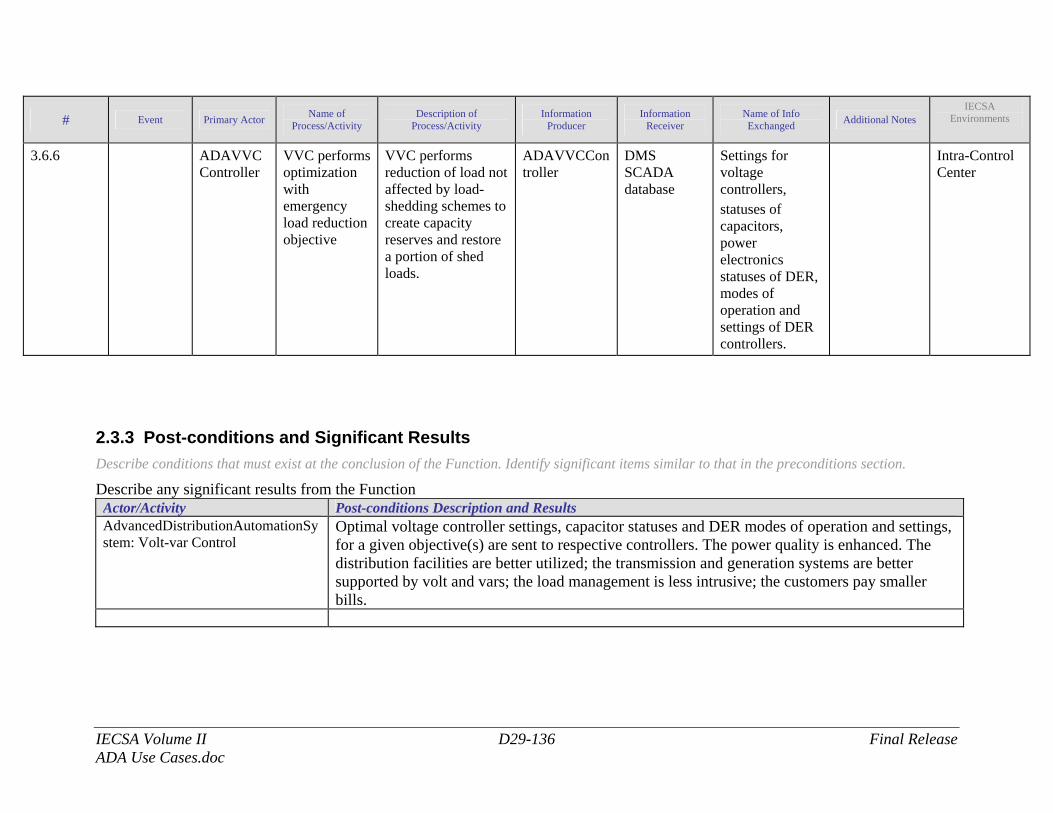
IECSA Volume II D29-136 Final Release ADA Use Cases.doc
# Event Primary Actor Name of Process/Activity
Description of Process/Activity
Information Producer
Information Receiver
Name of Info Exchanged Additional Notes
IECSA Environments
3.6.6 ADAVVCController
VVC performs optimization with emergency load reduction objective
VVC performs reduction of load not affected by load-shedding schemes to create capacity reserves and restore a portion of shed loads.
ADAVVCController
DMS SCADA database
Settings for voltage controllers, statuses of capacitors, power electronics statuses of DER, modes of operation and settings of DER controllers.
Intra-Control Center
2.3.3 Post-conditions and Significant Results Describe conditions that must exist at the conclusion of the Function. Identify significant items similar to that in the preconditions section.
Describe any significant results from the Function Actor/Activity Post-conditions Description and Results AdvancedDistributionAutomationSystem: Volt-var Control
Optimal voltage controller settings, capacitor statuses and DER modes of operation and settings, for a given objective(s) are sent to respective controllers. The power quality is enhanced. The distribution facilities are better utilized; the transmission and generation systems are better supported by volt and vars; the load management is less intrusive; the customers pay smaller bills.
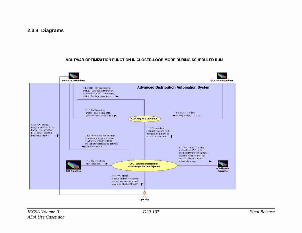
IECSA Volume II D29-137 Final Release ADA Use Cases.doc
2.3.4 Diagrams
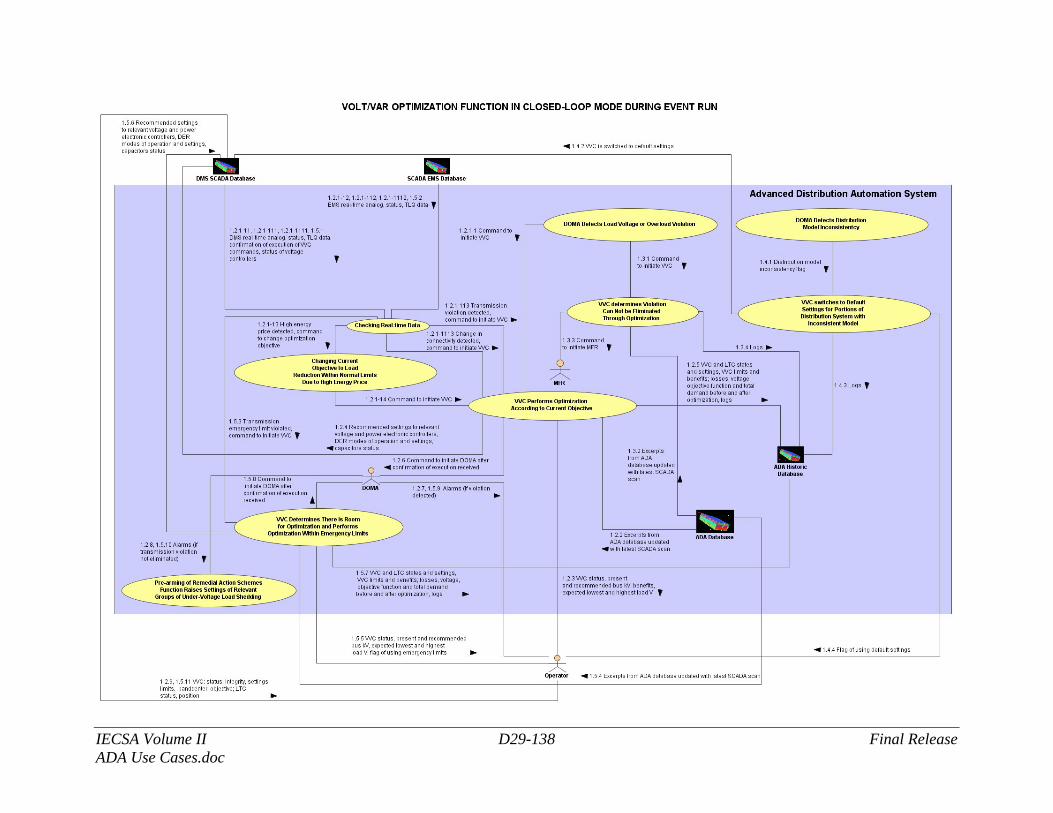
IECSA Volume II D29-138 Final Release ADA Use Cases.doc
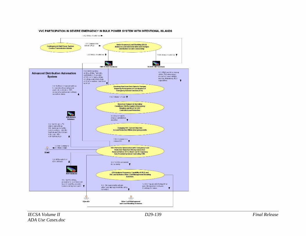
IECSA Volume II D29-139 Final Release ADA Use Cases.doc
IECSA Volume II D29-140 Final Release ADA Use Cases.doc
2.4 Architectural Issues in Interactions Elaborate on all architectural issues in each of the steps outlined in each of the sequences above. Reference the Step by number..
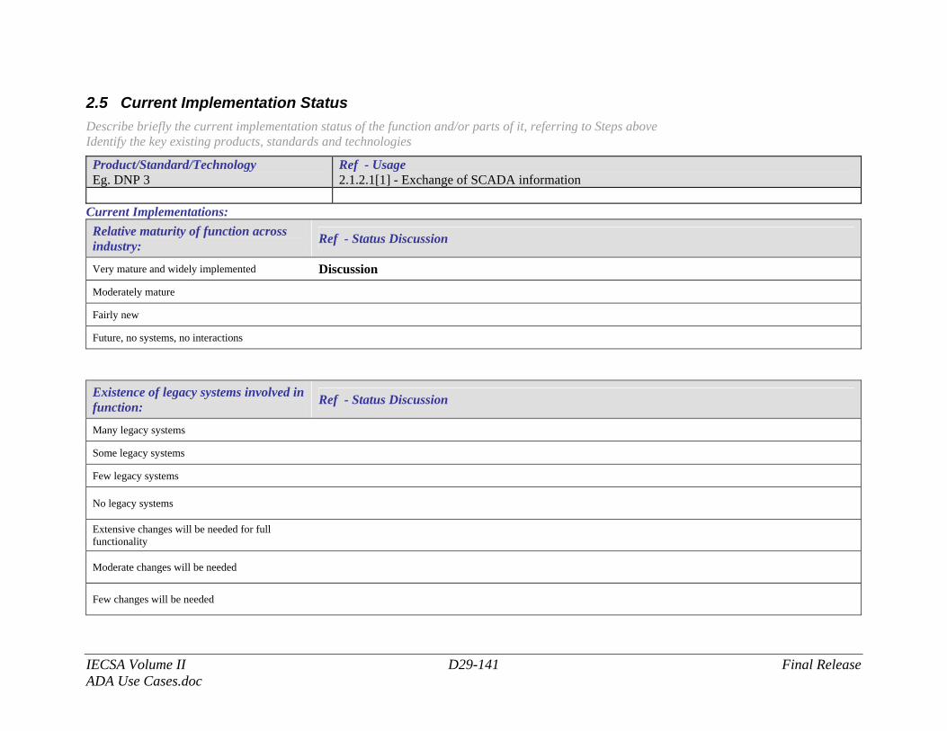
IECSA Volume II D29-141 Final Release ADA Use Cases.doc
2.5 Current Implementation Status Describe briefly the current implementation status of the function and/or parts of it, referring to Steps above Identify the key existing products, standards and technologies
Product/Standard/Technology Eg. DNP 3
Ref - Usage 2.1.2.1[1] - Exchange of SCADA information
Current Implementations: Relative maturity of function across industry: Ref - Status Discussion
Very mature and widely implemented Discussion
Moderately mature
Fairly new
Future, no systems, no interactions
Existence of legacy systems involved in function: Ref - Status Discussion
Many legacy systems
Some legacy systems
Few legacy systems
No legacy systems
Extensive changes will be needed for full functionality
Moderate changes will be needed
Few changes will be needed
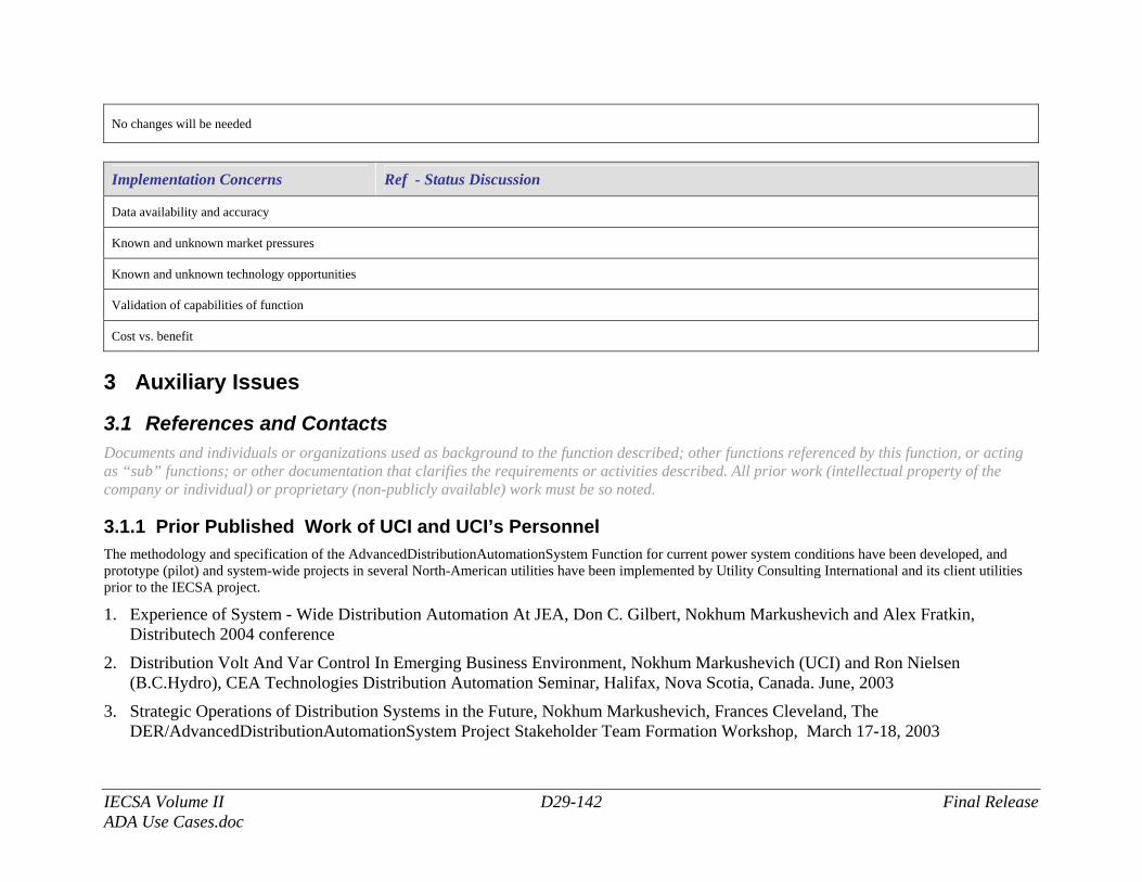
IECSA Volume II D29-142 Final Release ADA Use Cases.doc
No changes will be needed
Implementation Concerns Ref - Status Discussion
Data availability and accuracy
Known and unknown market pressures
Known and unknown technology opportunities
Validation of capabilities of function
Cost vs. benefit
3 Auxiliary Issues
3.1 References and Contacts Documents and individuals or organizations used as background to the function described; other functions referenced by this function, or acting as “sub” functions; or other documentation that clarifies the requirements or activities described. All prior work (intellectual property of the company or individual) or proprietary (non-publicly available) work must be so noted.
3.1.1 Prior Published Work of UCI and UCI’s Personnel The methodology and specification of the AdvancedDistributionAutomationSystem Function for current power system conditions have been developed, and prototype (pilot) and system-wide projects in several North-American utilities have been implemented by Utility Consulting International and its client utilities prior to the IECSA project.
1. Experience of System - Wide Distribution Automation At JEA, Don C. Gilbert, Nokhum Markushevich and Alex Fratkin, Distributech 2004 conference
2. Distribution Volt And Var Control In Emerging Business Environment, Nokhum Markushevich (UCI) and Ron Nielsen (B.C.Hydro), CEA Technologies Distribution Automation Seminar, Halifax, Nova Scotia, Canada. June, 2003
3. Strategic Operations of Distribution Systems in the Future, Nokhum Markushevich, Frances Cleveland, The DER/AdvancedDistributionAutomationSystem Project Stakeholder Team Formation Workshop, March 17-18, 2003
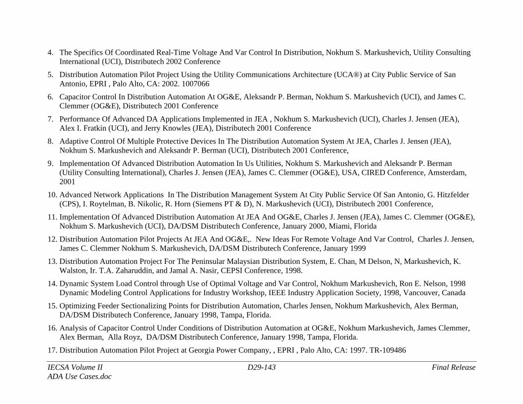
IECSA Volume II D29-143 Final Release ADA Use Cases.doc
4. The Specifics Of Coordinated Real-Time Voltage And Var Control In Distribution, Nokhum S. Markushevich, Utility Consulting International (UCI), Distributech 2002 Conference
5. Distribution Automation Pilot Project Using the Utility Communications Architecture (UCA®) at City Public Service of San Antonio, EPRI , Palo Alto, CA: 2002. 1007066
6. Capacitor Control In Distribution Automation At OG&E, Aleksandr P. Berman, Nokhum S. Markushevich (UCI), and James C. Clemmer (OG&E), Distributech 2001 Conference
7. Performance Of Advanced DA Applications Implemented in JEA , Nokhum S. Markushevich (UCI), Charles J. Jensen (JEA), Alex I. Fratkin (UCI), and Jerry Knowles (JEA), Distributech 2001 Conference
8. Adaptive Control Of Multiple Protective Devices In The Distribution Automation System At JEA, Charles J. Jensen (JEA), Nokhum S. Markushevich and Aleksandr P. Berman (UCI), Distributech 2001 Conference,
9. Implementation Of Advanced Distribution Automation In Us Utilities, Nokhum S. Markushevich and Aleksandr P. Berman (Utility Consulting International), Charles J. Jensen (JEA), James C. Clemmer (OG&E), USA, CIRED Conference, Amsterdam, 2001
10. Advanced Network Applications In The Distribution Management System At City Public Service Of San Antonio, G. Hitzfelder (CPS), I. Roytelman, B. Nikolic, R. Horn (Siemens PT & D), N. Markushevich (UCI), Distributech 2001 Conference,
11. Implementation Of Advanced Distribution Automation At JEA And OG&E, Charles J. Jensen (JEA), James C. Clemmer (OG&E), Nokhum S. Markushevich (UCI), DA/DSM Distributech Conference, January 2000, Miami, Florida
12. Distribution Automation Pilot Projects At JEA And OG&E,. New Ideas For Remote Voltage And Var Control, Charles J. Jensen, James C. Clemmer Nokhum S. Markushevich, DA/DSM Distributech Conference, January 1999
13. Distribution Automation Project For The Peninsular Malaysian Distribution System, E. Chan, M Delson, N, Markushevich, K. Walston, Ir. T.A. Zaharuddin, and Jamal A. Nasir, CEPSI Conference, 1998.
14. Dynamic System Load Control through Use of Optimal Voltage and Var Control, Nokhum Markushevich, Ron E. Nelson, 1998 Dynamic Modeling Control Applications for Industry Workshop, IEEE Industry Application Society, 1998, Vancouver, Canada
15. Optimizing Feeder Sectionalizing Points for Distribution Automation, Charles Jensen, Nokhum Markushevich, Alex Berman, DA/DSM Distributech Conference, January 1998, Tampa, Florida.
16. Analysis of Capacitor Control Under Conditions of Distribution Automation at OG&E, Nokhum Markushevich, James Clemmer, Alex Berman, Alla Royz, DA/DSM Distributech Conference, January 1998, Tampa, Florida.
17. Distribution Automation Pilot Project at Georgia Power Company, , EPRI , Palo Alto, CA: 1997. TR-109486
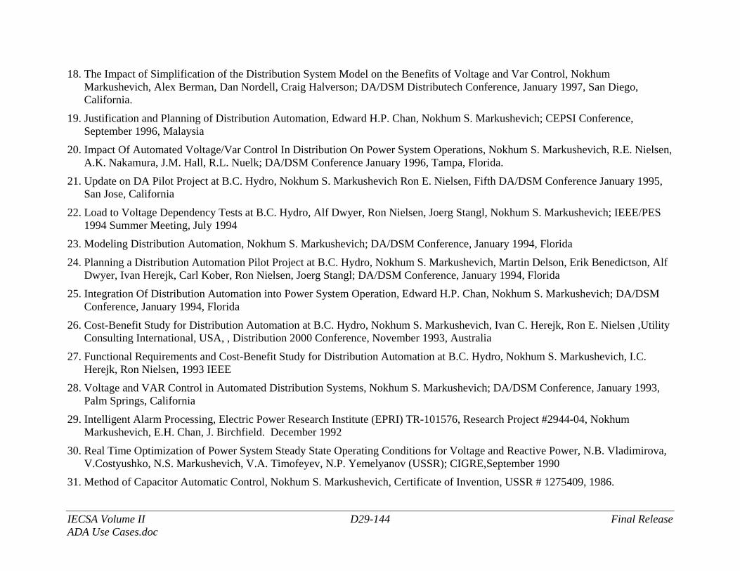
IECSA Volume II D29-144 Final Release ADA Use Cases.doc
18. The Impact of Simplification of the Distribution System Model on the Benefits of Voltage and Var Control, Nokhum Markushevich, Alex Berman, Dan Nordell, Craig Halverson; DA/DSM Distributech Conference, January 1997, San Diego, California.
19. Justification and Planning of Distribution Automation, Edward H.P. Chan, Nokhum S. Markushevich; CEPSI Conference, September 1996, Malaysia
20. Impact Of Automated Voltage/Var Control In Distribution On Power System Operations, Nokhum S. Markushevich, R.E. Nielsen, A.K. Nakamura, J.M. Hall, R.L. Nuelk; DA/DSM Conference January 1996, Tampa, Florida.
21. Update on DA Pilot Project at B.C. Hydro, Nokhum S. Markushevich Ron E. Nielsen, Fifth DA/DSM Conference January 1995, San Jose, California
22. Load to Voltage Dependency Tests at B.C. Hydro, Alf Dwyer, Ron Nielsen, Joerg Stangl, Nokhum S. Markushevich; IEEE/PES 1994 Summer Meeting, July 1994
23. Modeling Distribution Automation, Nokhum S. Markushevich; DA/DSM Conference, January 1994, Florida
24. Planning a Distribution Automation Pilot Project at B.C. Hydro, Nokhum S. Markushevich, Martin Delson, Erik Benedictson, Alf Dwyer, Ivan Herejk, Carl Kober, Ron Nielsen, Joerg Stangl; DA/DSM Conference, January 1994, Florida
25. Integration Of Distribution Automation into Power System Operation, Edward H.P. Chan, Nokhum S. Markushevich; DA/DSM Conference, January 1994, Florida
26. Cost-Benefit Study for Distribution Automation at B.C. Hydro, Nokhum S. Markushevich, Ivan C. Herejk, Ron E. Nielsen ,Utility Consulting International, USA, , Distribution 2000 Conference, November 1993, Australia
27. Functional Requirements and Cost-Benefit Study for Distribution Automation at B.C. Hydro, Nokhum S. Markushevich, I.C. Herejk, Ron Nielsen, 1993 IEEE
28. Voltage and VAR Control in Automated Distribution Systems, Nokhum S. Markushevich; DA/DSM Conference, January 1993, Palm Springs, California
29. Intelligent Alarm Processing, Electric Power Research Institute (EPRI) TR-101576, Research Project #2944-04, Nokhum Markushevich, E.H. Chan, J. Birchfield. December 1992
30. Real Time Optimization of Power System Steady State Operating Conditions for Voltage and Reactive Power, N.B. Vladimirova, V.Costyushko, N.S. Markushevich, V.A. Timofeyev, N.P. Yemelyanov (USSR); CIGRE,September 1990
31. Method of Capacitor Automatic Control, Nokhum S. Markushevich, Certificate of Invention, USSR # 1275409, 1986.
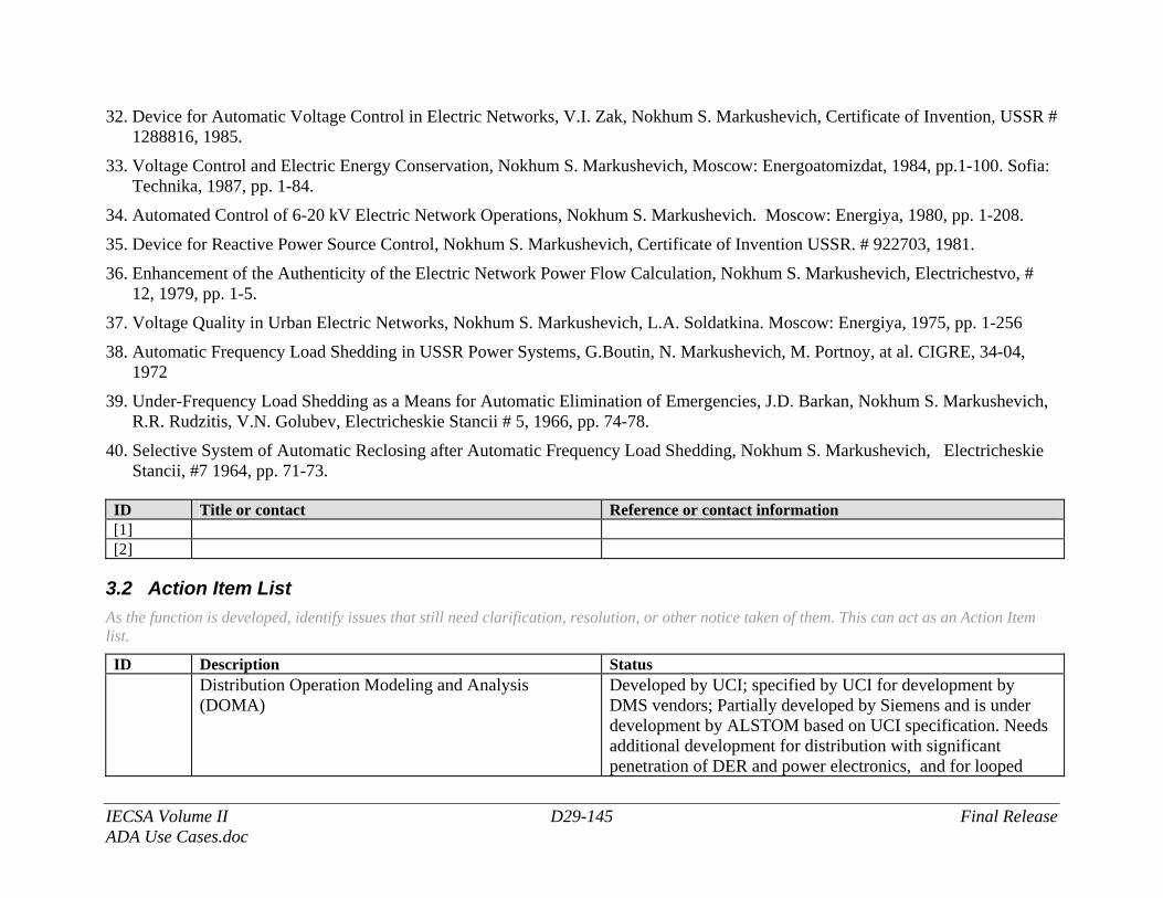
IECSA Volume II D29-145 Final Release ADA Use Cases.doc
32. Device for Automatic Voltage Control in Electric Networks, V.I. Zak, Nokhum S. Markushevich, Certificate of Invention, USSR # 1288816, 1985.
33. Voltage Control and Electric Energy Conservation, Nokhum S. Markushevich, Moscow: Energoatomizdat, 1984, pp.1-100. Sofia: Technika, 1987, pp. 1-84.
34. Automated Control of 6-20 kV Electric Network Operations, Nokhum S. Markushevich. Moscow: Energiya, 1980, pp. 1-208.
35. Device for Reactive Power Source Control, Nokhum S. Markushevich, Certificate of Invention USSR. # 922703, 1981.
36. Enhancement of the Authenticity of the Electric Network Power Flow Calculation, Nokhum S. Markushevich, Electrichestvo, # 12, 1979, pp. 1-5.
37. Voltage Quality in Urban Electric Networks, Nokhum S. Markushevich, L.A. Soldatkina. Moscow: Energiya, 1975, pp. 1-256
38. Automatic Frequency Load Shedding in USSR Power Systems, G.Boutin, N. Markushevich, M. Portnoy, at al. CIGRE, 34-04, 1972
39. Under-Frequency Load Shedding as a Means for Automatic Elimination of Emergencies, J.D. Barkan, Nokhum S. Markushevich, R.R. Rudzitis, V.N. Golubev, Electricheskie Stancii # 5, 1966, pp. 74-78.
40. Selective System of Automatic Reclosing after Automatic Frequency Load Shedding, Nokhum S. Markushevich, Electricheskie Stancii, #7 1964, pp. 71-73.
ID Title or contact Reference or contact information [1] [2]
3.2 Action Item List As the function is developed, identify issues that still need clarification, resolution, or other notice taken of them. This can act as an Action Item list.
ID Description Status
Distribution Operation Modeling and Analysis (DOMA)
Developed by UCI; specified by UCI for development by DMS vendors; Partially developed by Siemens and is under development by ALSTOM based on UCI specification. Needs additional development for distribution with significant penetration of DER and power electronics, and for looped
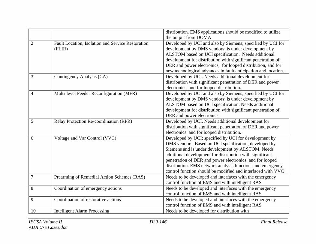
IECSA Volume II D29-146 Final Release ADA Use Cases.doc
distribution. EMS applications should be modified to utilize the output from DOMA
2 Fault Location, Isolation and Service Restoration (FLIR)
Developed by UCI and also by Siemens; specified by UCI for development by DMS vendors; is under development by ALSTOM based on UCI specification. Needs additional development for distribution with significant penetration of DER and power electronics, for looped distribution, and for new technological advances in fault anticipation and location.
3 Contingency Analysis (CA) Developed by UCI. Needs additional development for distribution with significant penetration of DER and power electronics and for looped distribution.
4 Multi-level Feeder Reconfiguration (MFR) Developed by UCI and also by Siemens; specified by UCI for development by DMS vendors; is under development by ALSTOM based on UCI specification. Needs additional development for distribution with significant penetration of DER and power electronics.
5 Relay Protection Re-coordination (RPR)
Developed by UCI. Needs additional development for distribution with significant penetration of DER and power electronics and for looped distribution.
6 Voltage and Var Control (VVC)
Developed by UCI; specified by UCI for development by DMS vendors. Based on UCI specification, developed by Siemens and is under development by ALSTOM. Needs additional development for distribution with significant penetration of DER and power electronics and for looped distribution. EMS network analysis functions and emergency control function should be modified and interfaced with VVC
7 Prearming of Remedial Action Schemes (RAS) Needs to be developed and interfaces with the emergency control function of EMS and with intelligent RAS
8 Coordination of emergency actions Needs to be developed and interfaces with the emergency control function of EMS and with intelligent RAS
9 Coordination of restorative actions Needs to be developed and interfaces with the emergency control function of EMS and with intelligent RAS
10 Intelligent Alarm Processing Needs to be developed for distribution with
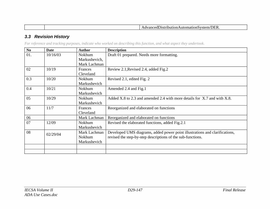
IECSA Volume II D29-147 Final Release ADA Use Cases.doc
AdvancedDistributionAutomationSystem/DER.
3.3 Revision History For reference and tracking purposes, indicate who worked on describing this function, and what aspect they undertook.
No Date Author Description 01. 10/16/03 Nokhum
Markushevich, Mark Lachman
Draft 01 prepared. Needs more formatting.
02 10/19 Frances Cleveland
Review 2.1,Revised 2.4, added Fig.2
0.3 10/20 Nokhum Markushevich
Revised 2.1, edited Fig. 2
0.4 10/21 Nokhum Markushevich
Amended 2.4 and Fig.1
05 10/29 Nokhum Markushevich
Added X.8 to 2.3 and amended 2.4 with more details for X.7 and with X.8.
06 11/7 Frances Cleveland
Reorganized and elaborated on functions
06 Mark Lachman Reorganized and elaborated on functions 07 12/09 Nokhum
Markushevich Revised the elaborated functions, added Fig.2.1
08 02/29/04 Mark Lachman Nokhum Markushevich
Developed UMS diagrams, added power point illustrations and clarifications, revised the step-by-step descriptions of the sub-functions.
IECSA Volume II D29-148 Final Release ADA Use Cases.doc
This page intentionally left blank.