adsp-2181 ez-kit lite evaluation system manualdan/2181_ez_kit_lite_legacy.pdf · xiv adsp-2181...
TRANSCRIPT
a
ADSP-2181 EZ-KIT Lite®
Evaluation System Manual
Revision 2.1, October 2003
Part Number82-000543-01
Analog Devices, Inc.One Technology WayNorwood, Mass. 02062-9106
Copyright Information© 2003 Analog Devices, Inc., ALL RIGHTS RESERVED. This docu-ment may not be reproduced in any form without prior, express written consent from Analog Devices, Inc.
Printed in the USA.
Limited WarrantyThe EZ-KIT Lite evaluation system is warranted against defects in materi-als and workmanship for a period of one year from the date of purchase from Analog Devices or from an authorized dealer.
DisclaimerAnalog Devices, Inc. reserves the right to change this product without prior notice. Information furnished by Analog Devices is believed to be accurate and reliable. However, no responsibility is assumed by Analog Devices for its use; nor for any infringement of patents or other rights of third parties which may result from its use. No license is granted by impli-cation or otherwise under the patent rights of Analog Devices, Inc.
Trademark and Service Mark NoticeThe Analog Devices logo, Blackfin, and EZ-KIT Lite are registered trade-marks of Analog Devices, Inc.
VisualDSP++ is a trademark of Analog Devices, Inc.
All other brand and product names are trademarks or service marks of their respective owners.
CONTENTS
PREFACE
Purpose of This Manual .................................................................. ix
Intended Audience ........................................................................... x
Manual Contents ............................................................................. x
What’s New in This Manual ............................................................ xi
Technical or Customer Support ....................................................... xi
Supported Processors ...................................................................... xii
Product Information ..................................................................... xiii
MyAnalog.com ........................................................................ xiii
DSP Product Information ........................................................ xiii
Related Documents .................................................................. xiv
Online Documentation ............................................................. xv
Printed Manuals ....................................................................... xvi
VisualDSP++ Documentation Set ......................................... xvi
Hardware Manuals ............................................................... xvi
Data Sheets .......................................................................... xvi
Contacting DSP Publications ................................................... xvii
Notation Conventions ................................................................... xvii
ADSP-2181 EZ-KIT Lite Evaluation System Manual iii
CONTENTS
GETTING STARTED
Contents of EZ-KIT Lite Package ................................................. 1-2
System Requirements .................................................................... 1-3
Installation Tasks .......................................................................... 1-3
Setting Up EZ-KIT Lite Hardware .......................................... 1-4
Installing VisualDSP++ and EZ-KIT Lite Software .................. 1-5
Installing VisualDSP++ License ............................................... 1-6
USING EZ-KIT LITE SOFTWARE
EZ-KIT Lite License Restrictions .................................................. 2-2
Memory Map ............................................................................... 2-2
Standard Operations ..................................................................... 2-3
Default Settings ...................................................................... 2-3
Input and Output Devices ....................................................... 2-3
Flags .................................................................................. 2-4
Interrupts ........................................................................... 2-4
Serial Ports ......................................................................... 2-5
POST Routines ....................................................................... 2-5
Memory Checks ................................................................. 2-6
UART Checks .................................................................... 2-6
AD1847 Codec Check and Initialization ............................. 2-7
Monitor Program Operations .................................................. 2-7
Halt loop ........................................................................... 2-7
UART ISR ......................................................................... 2-8
iv ADSP-2181 EZ-KIT Lite Evaluation System Manual
CONTENTS
Command Processing .......................................................... 2-8
Software Breakpoints ............................................................... 2-9
AD1847 Codec Dual Analog Front End ................................... 2-9
AD1847 Codec Transmissions ................................................. 2-9
Using EZ-KIT Lite VisualDSP++ Interface .................................. 2-10
Developing Programs ............................................................. 2-10
Starting Visual DSP++ ........................................................... 2-11
Debugging With EZ-KIT Lite ............................................... 2-13
Loading Programs .................................................................. 2-13
Registers and Memory ....................................................... 2-14
Setting Breakpoints and Stepping ...................................... 2-14
Resetting EZ-KIT Lite Board ............................................ 2-14
Example Programs ................................................................. 2-15
ADPCM ........................................................................... 2-15
DTMF ............................................................................. 2-15
ECHO ............................................................................. 2-15
FIRDEMO ....................................................................... 2-16
LPC2K4 ........................................................................... 2-16
LPC7K8 ........................................................................... 2-16
PRIMES ........................................................................... 2-17
EZ-KIT HARDWARE REFERENCE
System Architecture ...................................................................... 3-2
Board Layout ................................................................................ 3-3
Socketed Memory .................................................................... 3-4
ADSP-2181 EZ-KIT Lite Evaluation System Manual v
CONTENTS
User LEDs .............................................................................. 3-4
Switches .................................................................................. 3-4
Connectors ................................................................................... 3-5
Expansion Port Connectors ..................................................... 3-7
Power Connector .................................................................... 3-9
European Power Supply Connections .................................. 3-9
AD1847 Codec Connectors .................................................... 3-9
EPROM Jumper Settings ...................................................... 3-10
EZ-ICE Connector ............................................................... 3-12
Hardware Operation ............................................................. 3-13
Hardware Debugging ............................................................ 3-13
Designing EZ-ICE Compatible Systems ...................................... 3-14
RESTRICTIONS
BILL OF MATERIALS
INDEX
vi ADSP-2181 EZ-KIT Lite Evaluation System Manual
PREFACE
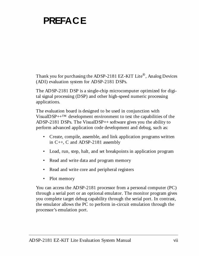
Thank you for purchasing the ADSP-2181 EZ-KIT Lite®, Analog Devices
(ADI) evaluation system for ADSP-2181 DSPs.The ADSP-2181 DSP is a single-chip microcomputer optimized for digi-tal signal processing (DSP) and other high-speed numeric processing applications.
The evaluation board is designed to be used in conjunction with VisualDSP++™ development environment to test the capabilities of the ADSP-2181 DSPs. The VisualDSP++ software gives you the ability to perform advanced application code development and debug, such as:
• Create, compile, assemble, and link application programs written in C++, C and ADSP-2181 assembly
• Load, run, step, halt, and set breakpoints in application program
• Read and write data and program memory
• Read and write core and peripheral registers
• Plot memory
You can access the ADSP-2181 processor from a personal computer (PC) through a serial port or an optional emulator. The monitor program gives you complete target debug capability through the serial port. In contrast, the emulator allows the PC to perform in-circuit emulation through the processor’s emulation port.
ADSP-2181 EZ-KIT Lite Evaluation System Manual vii
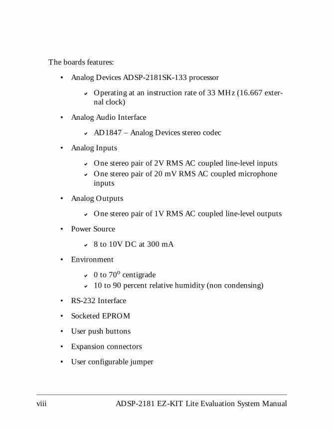
The boards features:
• Analog Devices ADSP-2181SK-133 processor
! Operating at an instruction rate of 33 MHz (16.667 exter-nal clock)
• Analog Audio Interface
! AD1847 – Analog Devices stereo codec
• Analog Inputs
! One stereo pair of 2V RMS AC coupled line-level inputs ! One stereo pair of 20 mV RMS AC coupled microphone
inputs
• Analog Outputs
! One stereo pair of 1V RMS AC coupled line-level outputs
• Power Source
! 8 to 10V DC at 300 mA
• Environment
! 0 to 70o centigrade! 10 to 90 percent relative humidity (non condensing)
• RS-232 Interface
• Socketed EPROM
• User push buttons
• Expansion connectors
• User configurable jumper
viii ADSP-2181 EZ-KIT Lite Evaluation System Manual
Preface
The ADSP-2181 EZ-KIT Lite board is equipped with hardware that facil-itates interactive demonstrations. Push button switches and user programmable LEDs provide user control and board status checking. Additionally, the AD1847 SoundPort codec provides access to an audio input (selectable as line level or microphone) and an audio output (line level). To learn more about AD1847 codec, refer to the AD1847 General Purpose Analog Front End data sheet found at http://www.analog.com/Uploaded-
Files/Obsolete_Data_Sheets/1215246AD1847.pdf.
The ADSP-2181 EZ-KIT Lite includes a monitor program stored in the socketed EPROM. The monitor program lets the board communicate over the serial port to a PC. This monitor program lets you download, execute, and debug ADSP-2181 programs.
You can also connect an EZ-ICE (in-circuit emulator) to the EZ-KIT Lite. Through the EZ-ICE, you can load programs, start and stop pro-gram execution, observe and alter registers and memory, and perform other debugging operations. To learn more about Analog Devices emula-tors and DSP development tools, go to http://www.analog.com/dsp/tools/.
Additionally, the EZ-KIT Lite provides user installed expansion connec-tors that let you examine processor signals, as well as provide an interface for host control.
" The VisualDSP++ licence provided with this EZ-KIT Lite evalua-tion system limits the size of a user program to 8K bytes of internal memory.
Purpose of This Manual The ADSP-2181 EZ-KIT Lite Evaluation System Manual provides instruc-tions for using the hardware and installing the software on your PC. This manual provides guidelines for running your own code on the
ADSP-2181 EZ-KIT Lite Evaluation System Manual ix
Intended Audience
ADSP-2181 EZ-KIT Lite. The manual also describes the operation and configuration of the evaluation board’s components. Finally, a bill of materials are provided as a reference for future ADSP-2181 board designs.
Intended AudienceThis manual is a user’s guide and reference to the ADSP-2181 EZ-KIT Lite evaluation system. Programmers who are familiar with the Analog Devices processor architecture, operation, and programming are the pri-mary audience for this manual.
Programmers who are unfamiliar with Analog Devices 16-bit fixed-point processors can use this manual in conjunction with the ADSP-218x DSP Hardware Reference and the ADSP-218x DSP Instruction Set Reference, which describe the processor architecture and instruction set. Program-mers who are unfamiliar with VisualDSP++ should refer to the VisualDSP++ online Help and the VisualDSP++ user’s or getting started guides. For the locations of these documents, refer to “Related Documents”.
Manual ContentsThe manual consists of:
• Chapter 1,“Getting Started” on page 1-1Provides software and hardware installation procedures, PC system requirements, and basic board information.
• Chapter 2, “Using EZ-KIT LITE Software” on page 2-1Provides information on the EZ-KIT Lite from a programmer’s perspective and provides an easy-to-access memory map.
x ADSP-2181 EZ-KIT Lite Evaluation System Manual
Preface
• Chapter 3, “EZ-KIT Hardware Reference” on page 3-1Provides information on the hardware aspects of the evaluation system.
• Appendix A, “Restrictions” on page A-1Provides a list of restrictions applicable to Release 1.1 of the ADSP-2181 EZ-KIT Lite evaluation board.
• Appendix B, “Bill Of Materials” on page B-1Provides a list of components used to manufacture the EZ-KIT Lite.
What’s New in This Manual This is the second revision of the ADSP-2181 EZ-KIT Lite Evaluation Sys-tem Manual. The manual provides the updated listing of related documents, updated installation procedure and Bill of Materials, and additional information on the processor’s internal memory.
Technical or Customer SupportYou can reach DSP Tools Support in the following ways.
• Visit the DSP Development Tools website at
www.analog.com/technology/dsp/developmentTools/index.html
• Email questions to
• Phone questions to 1-800-ANALOGD
• Contact your ADI local sales office or authorized distributor
• Send questions by mail to
ADSP-2181 EZ-KIT Lite Evaluation System Manual xi
Supported Processors
Analog Devices, Inc.
One Technology Way
P.O. Box 9106
Norwood, MA 02062-9106
USA
Supported ProcessorsThe ADSP-2181 EZ-KIT Lite evaluation system supports ADSP-2181 Analog Devices microprocessors.
xii ADSP-2181 EZ-KIT Lite Evaluation System Manual
Preface
Product InformationYou can obtain product information from the Analog Devices website, from the product CD-ROM, or from the printed publications (manuals).
Analog Devices is online at www.analog.com. Our website provides infor-mation about a broad range of products—analog integrated circuits, amplifiers, converters, and digital signal processors.
MyAnalog.comMyAnalog.com is a free feature of the Analog Devices website that allows customization of a webpage to display only the latest information on products you are interested in. You can also choose to receive weekly email notification containing updates to the webpages that meet your interests. MyAnalog.com provides access to books, application notes, data sheets, code examples, and more.
Registration:
Visit www.myanalog.com to sign up. Click Register to use MyAnalog.com. Registration takes about five minutes and serves as means for you to select the information you want to receive.
If you are already a registered user, just log on. Your user name is your email address.
DSP Product InformationFor information on digital signal processors, visit our website at www.analog.com/dsp, which provides access to technical publications, data sheets, application notes, product overviews, and product announcements.
ADSP-2181 EZ-KIT Lite Evaluation System Manual xiii
Product Information
You may also obtain additional information about Analog Devices and its products in any of the following ways.
• Email questions or requests for information to [email protected]
• Fax questions or requests for information to 1-781-461-3010 (North America) or +49 (0) 89 76903-157 (Europe)
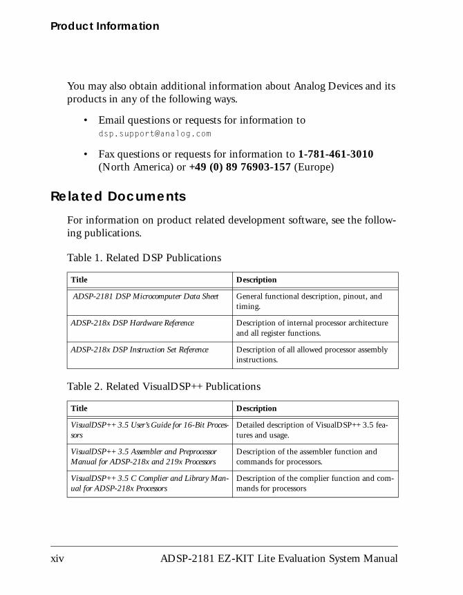
Related DocumentsFor information on product related development software, see the follow-ing publications.
Table 1. Related DSP Publications
Title Description
ADSP-2181 DSP Microcomputer Data Sheet General functional description, pinout, and timing.
ADSP-218x DSP Hardware Reference Description of internal processor architecture and all register functions.
ADSP-218x DSP Instruction Set Reference Description of all allowed processor assembly instructions.
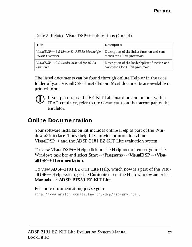
Table 2. Related VisualDSP++ Publications
Title Description
VisualDSP++ 3.5 User’s Guide for 16-Bit Proces-sors
Detailed description of VisualDSP++ 3.5 fea-tures and usage.
VisualDSP++ 3.5 Assembler and Preprocessor Manual for ADSP-218x and 219x Processors
Description of the assembler function and commands for processors.
VisualDSP++ 3.5 C Complier and Library Man-ual for ADSP-218x Processors
Description of the complier function and com-mands for processors
xiv ADSP-2181 EZ-KIT Lite Evaluation System Manual
Preface
The listed documents can be found through online Help or in the Docs folder of your VisualDSP++ installation. Most documents are available in printed form.
" If you plan to use the EZ-KIT Lite board in conjunction with a JTAG emulator, refer to the documentation that accompanies the emulator.
Online Documentation Your software installation kit includes online Help as part of the Win-dows® interface. These help files provide information about VisualDSP++ and the ADSP-2181 EZ-KIT Lite evaluation system.
To view VisualDSP++ Help, click on the Help menu item or go to the Windows task bar and select Start -->Programs -->VisualDSP -->Visu-alDSP++ Documentation.
To view ADSP-2181 EZ-KIT Lite Help, which now is a part of the Visu-alDSP++ Help system, go the Contents tab of the Help window and select Manuals --> ADSP-BF533 EZ-KIT Lite.
For more documentation, please go to http://www.analog.com/technology/dsp/library.html.
VisualDSP++ 3.5 Linker & Utilities Manual for 16-Bit Processors
Description of the linker function and com-mands for 16-bit processors.
VisualDSP++ 3.5 Loader Manual for 16-Bit Processors
Description of the loader/splitter function and commands for 16-bit processors.
Table 2. Related VisualDSP++ Publications (Cont’d)
Title Description
ADSP-2181 EZ-KIT Lite Evaluation System Manual xv BookTitle2
Product Information
Printed ManualsFor general questions regarding literature ordering, call the Literature Center at 1-800-ANALOGD (1-800-262-5643) and follow the prompts.
VisualDSP++ Documentation Set
Printed copies of VisualDSP++ manuals may be purchased through Ana-log Devices Customer Service at 1-781-329-4700; ask for a Customer Service representative. The manuals can be purchased only as a kit. For additional information, call 1-603-883-2430.
If you do not have an account with Analog Devices, you will be referred to Analog Devices distributors. To get information on our distributors, log onto www.analog.com/salesdir/continent.asp.
Hardware Manuals
Printed copies of hardware reference and instruction set reference manuals can be ordered through the Literature Center or downloaded from the Analog Devices website. The phone number is 1-800-ANALOGD (1-800-262-5643). The manuals can be ordered by a title or by product number located on the back cover of each manual.
Data Sheets
All data sheets can be downloaded from the Analog Devices website. As a general rule, printed copies of data sheets with a letter suffix (L, M, N, S) can be obtained from the Literature Center at 1-800-ANALOGD (1-800-262-5643) or downloaded from the website. Data sheets without the suffix can be downloaded from the website only—no hard copies are available. You can ask for the data sheet by part name or by product number.
xvi ADSP-2181 EZ-KIT Lite Evaluation System ManualBookTitle2
Preface
If you want to have a data sheet faxed to you, the phone number for that service is 1-800-446-6212. Follow the prompts and a list of data sheet code numbers will be faxed to you. Call the Literature Center first to find out if requested data sheets are available.
Contacting DSP PublicationsPlease send your comments and recommendations on how to improve our manuals and online Help. You can contact us at [email protected] .
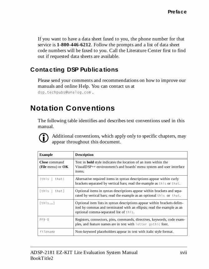
Notation ConventionsThe following table identifies and describes text conventions used in this manual.
" Additional conventions, which apply only to specific chapters, may appear throughout this document.
Example Description
Close command (File menu) or OK
Text in bold style indicates the location of an item within the VisualDSP++ environment’s and boards’ menu system and user interface items.
{this | that} Alternative required items in syntax descriptions appear within curly brackets separated by vertical bars; read the example as this or that.
[this | that] Optional items in syntax descriptions appear within brackets and sepa-rated by vertical bars; read the example as an optional this or that.
[this,…] Optional item lists in syntax descriptions appear within brackets delim-ited by commas and terminated with an ellipsis; read the example as an optional comma-separated list of this.
PF9-0 Registers, connectors, pins, commands, directives, keywords, code exam-ples, and feature names are in text with letter gothic font.
filename Non-keyword placeholders appear in text with italic style format.
ADSP-2181 EZ-KIT Lite Evaluation System Manual xvii BookTitle2
Notation Conventions
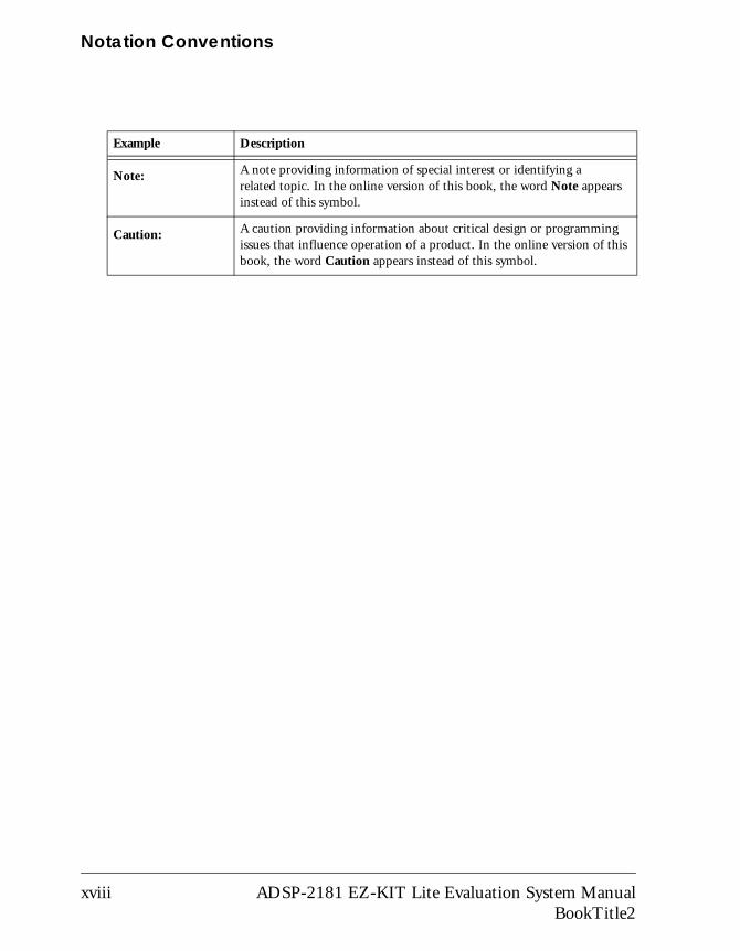
Note: A note providing information of special interest or identifying a related topic. In the online version of this book, the word Note appears instead of this symbol.
Caution: A caution providing information about critical design or programming issues that influence operation of a product. In the online version of this book, the word Caution appears instead of this symbol.
Example Description
xviii ADSP-2181 EZ-KIT Lite Evaluation System ManualBookTitle2
1 GETTING STARTED
This chapter provides the information you need to begin using
ADSP-2181 EZ-KIT Lite evaluation system. For correct operation, install the software and hardware in the order presented in “Installation Tasks” on page 1-3.The chapter includes the following sections.
• “Contents of EZ-KIT Lite Package” on page 1-2Provides a list of the components shipped with this EZ-KIT Lite evaluation system.
• “System Requirements” on page 1-3Describes the minimum requirements for the PC to work with the EZ-KIT Lite evaluation system.
• “Installation Tasks” on page 1-3Describes the step-by-step procedures for setting up the hardware and software.
ADSP-2181 EZ-KIT Lite Evaluation System Manual 1-1
Contents of EZ-KIT Lite Package
Contents of EZ-KIT Lite PackageYour ADSP-2181 EZ-KIT Lite evaluation system package contains the following items.
• ADSP-2181 EZ-KIT Lite board
• Power cable with 8-10V DC power supply
• RS-232 serial port 9-pin cable
• CD containing:
! VisualDSP++ for 16-bit processors with a limited license ! ADSP-2181 EZ-KIT Lite debug software! Example programs! ADSP-2181 EZ-KIT Lite Evaluation System Manual (this
document)
If any item is missing, contact the vendor where you purchased your EZ-KIT Lite or contact Analog Devices, Inc.
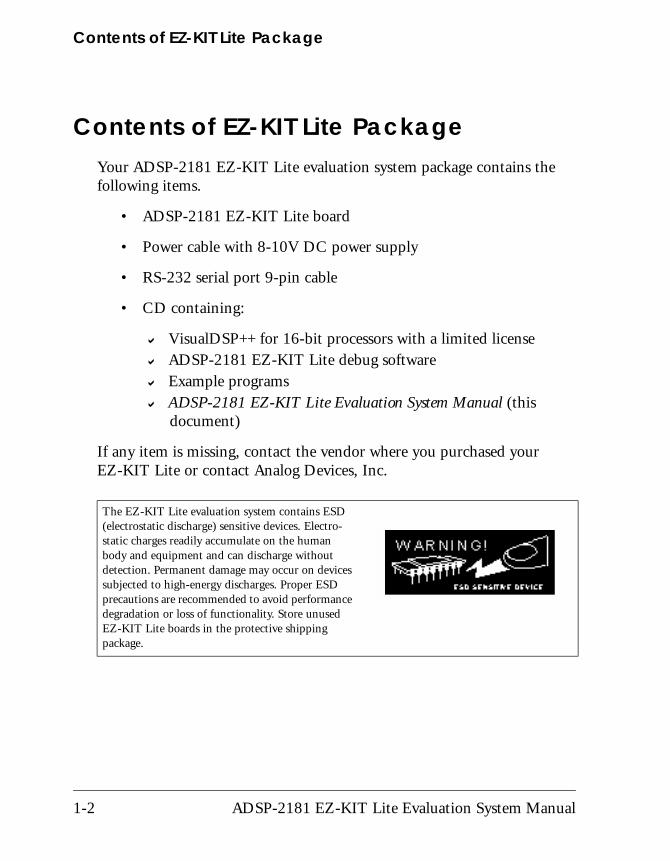
The EZ-KIT Lite evaluation system contains ESD (electrostatic discharge) sensitive devices. Electro-static charges readily accumulate on the human body and equipment and can discharge without detection. Permanent damage may occur on devices subjected to high-energy discharges. Proper ESD precautions are recommended to avoid performance degradation or loss of functionality. Store unused EZ-KIT Lite boards in the protective shipping package.
1-2 ADSP-2181 EZ-KIT Lite Evaluation System Manual
Getting Started
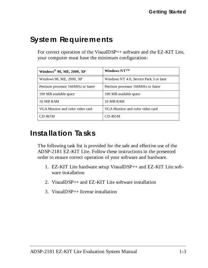
System RequirementsFor correct operation of the VisualDSP++ software and the EZ-KIT Lite, your computer must have the minimum configuration:
Installation TasksThe following task list is provided for the safe and effective use of the ADSP-2181 EZ-KIT Lite. Follow these instructions in the presented order to ensure correct operation of your software and hardware.
1. EZ-KIT Lite hardware setup VisualDSP++ and EZ-KIT Lite soft-ware installation
2. VisualDSP++ and EZ-KIT Lite software installation
3. VisualDSP++ license installation
Windows® 98, ME, 2000, XP Windows NTTM
Windows 98, ME, 2000, XP Windows NT 4.0, Service Pack 3 or later
Pentium processor 166MHz or faster Pentium processor 166MHz or faster
100 MB available space 100 MB available space
16 MB RAM 16 MB RAM
VGA Monitor and color video card VGA Monitor and color video card
CD-ROM CD-ROM
ADSP-2181 EZ-KIT Lite Evaluation System Manual 1-3
Installation Tasks
Setting Up EZ-KIT Lite Hardware
The ADSP-2181 EZ-KIT Lite board is designed to run outside your per-sonal computer as a stand-alone unit. You do not have to remove your computer case.
To connect the EZ-KIT Lite board:
1. Remove the EZ-KIT Lite board from the package. Be careful when handling the board to avoid the discharge of static electricity, which may damage some components.
2. Connect the RS-232 cable to an available Comm Port on the PC and to J3 on the ADSP-2181 evaluation board.
3. Plug the provided cord into a 120-Volt AC receptacle and plug the connector at the other end of the cable into J4 on the evaluation board. Visually verify that all of the LEDs light up briefly. The power (green) LED remains on and FL1 blinks. If the LED does not light up, check the power connections.
The EZ-KIT Lite evaluation system contains ESD (electrostatic discharge) sensitive devices. Electro-static charges readily accumulate on the human body and equipment and can discharge without detection. Permanent damage may occur on devices subjected to high-energy discharges. Proper ESD precautions are recommended to avoid performance degradation or loss of functionality. Store unused EZ-KIT Lite boards in the protective shipping package.
1-4 ADSP-2181 EZ-KIT Lite Evaluation System Manual
Getting Started
To configure your board to take advantage of the audio capabilities of the demos, use the following procedure.
1. Plug a set of self-powered computer speakers into jack J1 on the board. Turn on the speakers and set the volume to an adequate level.
2. Connect the line out of an electronic audio device to jack J2 on the board. Set jumper JP2 to LINE.
3. Open Jumper JP2 to GND to enable the AD1847 codec. (This is the board default).
This completes the hardware installation. For information about the EZ-KIT Lite hardware design, refer to “Board Layout” on page 3-3.
Installing VisualDSP++ and EZ-KIT Lite SoftwareThis EZ-KIT Lite comes with the latest version of VisualDSP++ for 16-bit processors. VisualDSP++ installation includes EZ-KIT Lite installations.
To install VisualDSP++ and EZ-KIT Lite software:
1. Insert the VisualDSP++ installation CD into the CD-ROM drive.
2. If Autoplay is enabled on your PC, you see the Install Shield Wiz-ard Welcome screen. Otherwise, choose Run from the Start menu, and enter D:\ADI_Setup.exe in the Open field, where D is the name of your local CD-ROM drive.
3. Follow the on-screen instructions to continue installing the software.
4. At the Custom Setup screen, select your EZ-KIT Lite from the list of available systems and choose the installation directory.
ADSP-2181 EZ-KIT Lite Evaluation System Manual 1-5
Installation Tasks
Click an icon in the Feature Description field to see the selected system’s description. When you have finished, click Next.
5. At the Ready to Install screen, click Back to change your install options, click Install to install the software, or click Cancel to exit the install.
6. When the EZ-KIT Lite installs, the Wizard Completed screen appears. Click Finish.
Installing VisualDSP++ LicenseTo install the VisualDSP++ license:
1. Locate the serial number provided on the sticker affixed to the CD sleeve and the registration form.
2. From the Start menu, choose Programs, Analog Devices, Visu-alDSP++ 3.5 for 16-bit Processors, VisualDSP++ Environment.
3. The information screen asks if you would like to install a license. Click Yes. The About VisualDSP++ screen appears.
4. Select the Licenses tab and click New.
5. In the Install a New License dialog that opens, select Single User.
" Please note that the VisualDSP++ software that comes with your EZ-KIT Lite is a demo version that limits executable file size to 8K bytes. This license lets you run EZ-KIT Lite sessions only. Simula-tion and emulation are not supported. For a full license, contact your local Analog Devices Sales representative.
6. Fill in the tools serial number in the field provided exactly as it appears on your CD sleeve or registration form and click Next. An information window notifies of successful license installation.
1-6 ADSP-2181 EZ-KIT Lite Evaluation System Manual
2 USING EZ-KIT LITE SOFTWARE
The combination of the EZ-KIT Lite board and the monitor software
operate as a target for the VisualDSP++ debugger. The debugger lets you view the ADSP-2181processor’s registers and memory and perform several debugging activities, such as setting breakpoints, stepping through code, and plotting a range of memory.The information in this chapter is organized as follows.
• “EZ-KIT Lite License Restrictions” on page 2-2Describes the restrictions of the VisualDSP++ license shipped with the EZ-KIT Lite.
• “Memory Map” on page 2-2Defines the ADSP-2181 EZ-KIT Lite board’s memory map.
• “Standard Operations” on page 2-3Covers the standard operation of the EZ-KIT Lite board.
• “Using EZ-KIT Lite VisualDSP++ Interface” on page 2-10Describes the facilities of the EZ-KIT Lite graphical user interface.
ADSP-2181 EZ-KIT Lite Evaluation System Manual 2-1
EZ-KIT Lite License Restrictions
EZ-KIT Lite License RestrictionsThe license shipped with the EZ-KIT Lite imposes the following restrictions.
• The size of a user program is limited to 8 KB of the ADSP-2181 processor’s internal memory space.
• No connections to Simulator or Emulator sessions are allowed.
• Only one EZ-KIT Lite board can be connected to the host PC and debugged at a time.
• The EZ-KIT Lite hardware must be connected and powered up in order to use VisualDSP++ with a kit license.
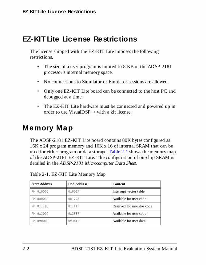
Memory MapThe ADSP-2181 EZ-KIT Lite board contains 80K bytes configured as 16K x 24 program memory and 16K x 16 of internal SRAM that can be used for either program or data storage. Table 2-1 shows the memory map of the ADSP-2181 EZ-KIT Lite. The configuration of on-chip SRAM is detailed in the ADSP-2181 Microcomputer Data Sheet.
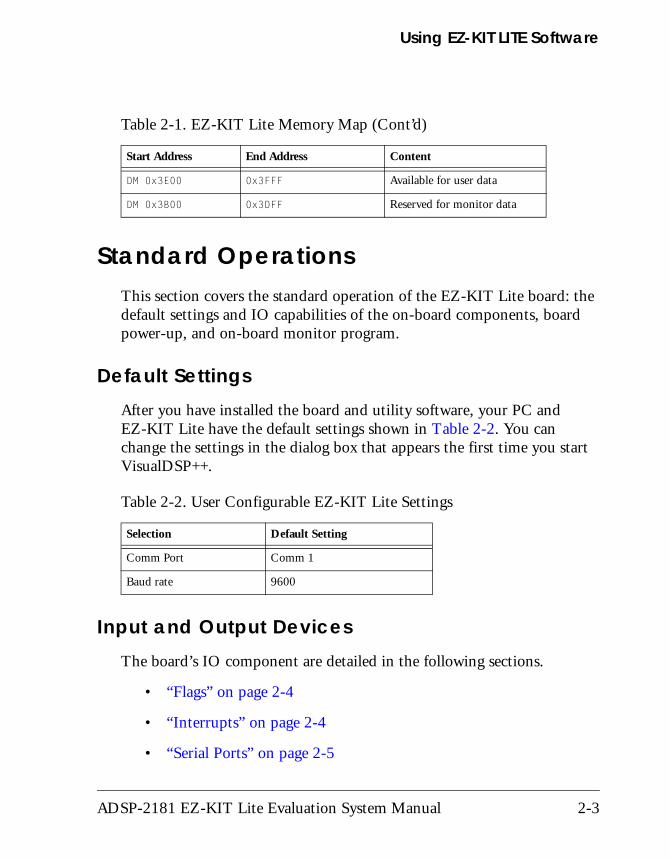
Table 2-1. EZ-KIT Lite Memory Map
Start Address End Address Content
PM 0x0000 0x002F Interrupt vector table
PM 0x0030 0x17CF Available for user code
PM 0x17D0 0x1FFF Reserved for monitor code
PM 0x2000 0x3FFF Available for user code
DM 0x0000 0x3AFF Available for user data
2-2 ADSP-2181 EZ-KIT Lite Evaluation System Manual
Using EZ-KIT LITE Software
Standard OperationsThis section covers the standard operation of the EZ-KIT Lite board: the default settings and IO capabilities of the on-board components, board power-up, and on-board monitor program.
Default SettingsAfter you have installed the board and utility software, your PC and EZ-KIT Lite have the default settings shown in Table 2-2. You can change the settings in the dialog box that appears the first time you start VisualDSP++.
Input and Output DevicesThe board’s IO component are detailed in the following sections.
• “Flags” on page 2-4
• “Interrupts” on page 2-4
• “Serial Ports” on page 2-5
DM 0x3E00 0x3FFF Available for user data
DM 0x3B00 0x3DFF Reserved for monitor data
Table 2-2. User Configurable EZ-KIT Lite Settings
Selection Default Setting
Comm Port Comm 1
Baud rate 9600
Table 2-1. EZ-KIT Lite Memory Map (Cont’d)
Start Address End Address Content
ADSP-2181 EZ-KIT Lite Evaluation System Manual 2-3
Standard Operations
Flags
The ADSP-2181 DSP has one asynchronous FLAG IO pin. The FL1 pin is connected to the red FL1 LED. This lets you visually inspect states of your program.
Interrupts
The ADSP-2181 EZ-KIT Lite has one external interrupt connected through a push button switch, S2. This corresponds to an external inter-rupt, IRQE.
The external interrupts are controlled through the ICNTL and IMASK regis-ters and are configured by modifying the interrupt vector table or through instructions in user code. The ICNTL register also controls the interrupt sensitivity between level and edge. To prevent an interrupt from being masked, write to the IMASK register.
The monitor program running on the ADSP-2181 DSP uses one interrupt (Timer) for normal operation. When downloading your own code through the monitor program, the timer interrupt vector is protected and cannot be overwritten. If these vectors are overwritten, or the timer interrupt is masked in any way, the debugger is not able to communicate with the host program. The following rules and restrictions should be followed when using interrupts.
• You cannot step into an interrupt
• Interrupts are disabled when the user program is halted
• The board cannot communicate with the host if interrupt nesting is enabled.
2-4 ADSP-2181 EZ-KIT Lite Evaluation System Manual
Using EZ-KIT LITE Software
Serial Ports
The ADSP-2181 DSP features two synchronous bi-directional Serial Ports (SPORTs), SPORT0 and SPORT1. The SPORTs can operate at up to 1x clock frequency, providing each with a maximum data rate of 30 Mbit/sec. SPORT data can be automatically transferred to and from on-chip memory using DMA.
SPORT0 is connected to the on-board AD1847 codec. The CODECDIS signal available on connector P3 can be used to disable the codec. When this sig-nal is brought low, the codec is disabled and its signals are put in a high impedance state. SPORT1 is connected to the RS-232 interface and is used as a software Universal Asynchronous Receiver/Transmitter (UART). Communications between the monitor and the host are through SPORT1.
For more information on the Serial Ports, refer to the ADSP-218x DSP Hardware Reference.
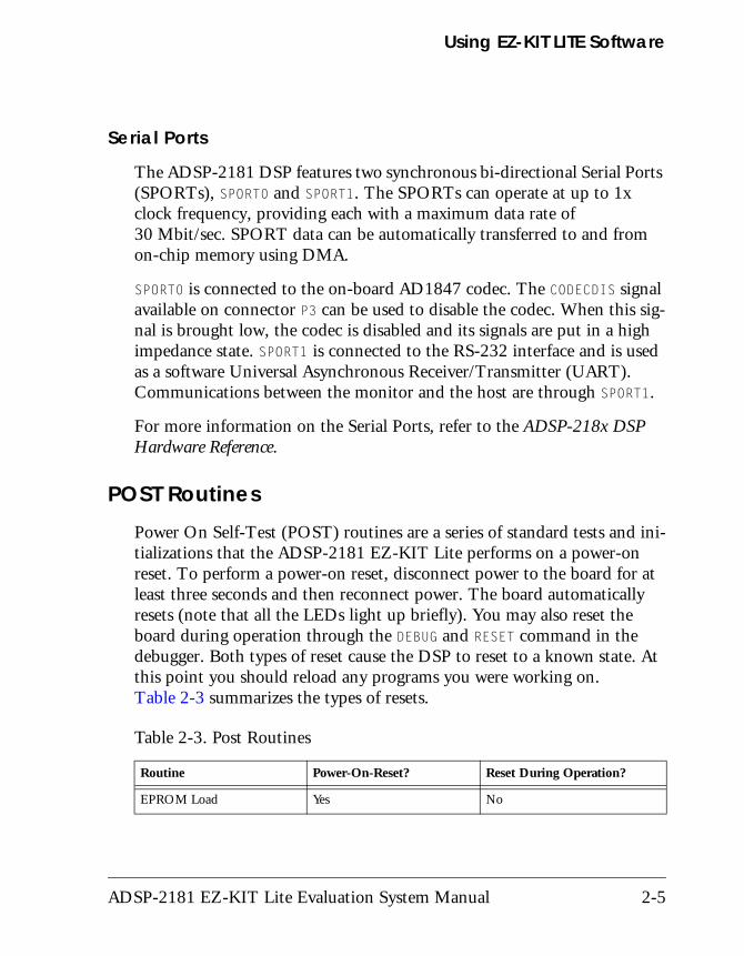
POST RoutinesPower On Self-Test (POST) routines are a series of standard tests and ini-tializations that the ADSP-2181 EZ-KIT Lite performs on a power-on reset. To perform a power-on reset, disconnect power to the board for at least three seconds and then reconnect power. The board automatically resets (note that all the LEDs light up briefly). You may also reset the board during operation through the DEBUG and RESET command in the debugger. Both types of reset cause the DSP to reset to a known state. At this point you should reload any programs you were working on. Table 2-3 summarizes the types of resets.
Table 2-3. Post Routines
Routine Power-On-Reset? Reset During Operation?
EPROM Load Yes No
ADSP-2181 EZ-KIT Lite Evaluation System Manual 2-5
Standard Operations
Memory Checks
The monitor program performs some standard memory checks on EPROM and internal RAM. The EPROM test consists of verifying a number in memory. If the monitor code is corrupted, the monitor may crash before reaching the actual program code.
UART Checks
The software UART check is done when it attempts to connect to the EZ-KIT Lite through a Transmitted Loop Back routine. This UART test is performed by the host after the POST is complete. In this test, the host sends the UART test protocol. This protocol specifies the number of bytes that are transmitted to the EZ-KIT Lite board and instructs the board to echo the byte stream back to the host. This test determines whether the EZ-KIT Lite board is set to the correct baud rate and verifies the external connections between the board and the host.
On power up, the EZ-KIT Lite board defaults to a baud rate of 9600 baud with 8 data bits, 1 stop bit, and no parity. To change this rate, wait for the POST routine to complete and then use the Settings, Baud Rate command in the debugger. Note that setting the baud rate to a lower number can significantly slow the board’s response to all debug activities.
Different baud rates depend upon your application’s type: for real-time interrupt driven programs, a lower baud rate setting slows performance, but the timer interrupt occurs less frequently. This gives your program a larger share of the processor’s resources.
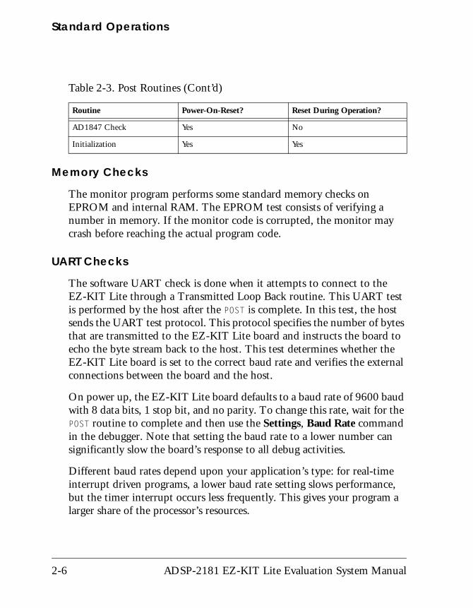
AD1847 Check Yes No
Initialization Yes Yes
Table 2-3. Post Routines (Cont’d)
Routine Power-On-Reset? Reset During Operation?
2-6 ADSP-2181 EZ-KIT Lite Evaluation System Manual

Using EZ-KIT LITE Software
AD1847 Codec Check and Initialization
On reset, the AD1847 codec is inactive. An initialization routine initial-izes the codec by sending a series of command words through the SPORT0 TX interrupt. Once the commands have been sent and the AD1847 initialized, it begins transmitting the clock, which synchronizes data transfers to and from the DSP. Once this bit goes “High”, the AD1847 is ready for standard communication over SPORT0.
Monitor Program OperationsThe monitor program runs on the EZ-KIT Lite board as part of the DSP executable and provides the ability to download, debug, and run user pro-grams. The VisualDSP++ debugger is the interface for the monitor program. Using the EZ-KIT Lite as a target with the debugger lets you operate the board remotely.
There are three main components of the monitor program:
• “Halt loop”
• “UART ISR”
• “Command Processing”
Halt loop
The monitor program idles in the halt loop when the program is not run-ning user code. While there, you can READ and WRITE memory and registers, download programs, set breakpoints, change the UART’s baud rate, and single step through your code. To enter the halt loop from code, you must suspend or stop the code, using either a breakpoint or a HALT instruction. At this point, the halt loop polls the UART. With every char-acter received from the UART, the command-processing kernel verifies whether a full command has been received. If a full command has been received, the kernel processes the command; otherwise, control is returned
ADSP-2181 EZ-KIT Lite Evaluation System Manual 2-7
Standard Operations
to the halt loop to wait for more characters. The only method of executing your code once the halt loop has been entered is to send a RUN or SINGLE STEP command in the debugger.
UART ISR
The UART Interrupt Service Routine (Timer ISR) is entered when your code is running, but the host is still interacting with the board. As the host sends bytes, the UART ISR takes the data stream from the UART and builds the command. As with the halt loop, each character received is passed to the command-processing kernel. Unlike the halt loop, the mon-itor returns to your code immediately after the interrupt is serviced.
# The following restrictions should be observed to ensure correct board operation.
• The host loses contact with the monitor while the user program is running if the user program disables the Timer interrupt or changes the Timer interrupt vector.
• The host loses contact with the monitor while the program is run-ning and it enters an Interrupt Service Routine when nesting is turned on.
• The host cannot halt with the debugger’s Debug, Halt command if global IRQ enable is disabled; however, breakpoints will work.
• The debugger will have trouble halting at a baud rate over 9600 while using the monitor program.
Command Processing
Command processing, initiated from either the UART ISR or the Halt loop, is done in the command-processing kernel. This kernel parses the commands and executes the instructions. If the instruction requires data to be sent back to the host, the kernel initiates the response.
2-8 ADSP-2181 EZ-KIT Lite Evaluation System Manual
Using EZ-KIT LITE Software
Software BreakpointsThe ability to stop the execution of code and examine processor registers and memory is extremely helpful when debugging code. Note that the debugger automatically inserts breakpoints at the function main(), when the Settings, Run To Main command is checked, and at the _exit instruction.
AD1847 Codec Dual Analog Front EndThe monitor does not initialize the AD1847codec. This provides you with greater flexibility to experiment with custom codec operations. Simple code examples, such as Echo, are provided with your EZ-KIT Lite to dem-onstrate some basic codec operations. It is recommended that you model your code using these examples.
AD1847 Codec TransmissionsAfter initialization, the AD1847 codec generates the clock used to transfer data across SPORT0. The ADSP-2181 DSP initiates all transmissions with the AD1847 device by sending a synchronization pulse. Even though the AD1847 transmits the data clock, it may not be ready for normal operation.
Initialization of the AD1847 codec is performed by sending 13 control words contained in a circular buffer to the AD1847 codec. This is usually done via the SPORT0 TX interrupt routine. Once the codec is initialized, autobuffering is used to fill up the TX and RX buffers, which use circular buffering. Once the circular buffer wraps around, then either a TX or RX interrupt occurs. Then the DSP processes the interrupt request.
ADSP-2181 EZ-KIT Lite Evaluation System Manual 2-9
Using EZ-KIT Lite VisualDSP++ Interface
Using EZ-KIT Lite VisualDSP++ InterfaceThis section outlines the process of developing, loading, and running the ADSP-2181 EZ-KIT Lite example programs supplied with VisualDSP++ software:
• “Developing Programs” on page 2-10
• “Starting Visual DSP++” on page 2-11
• “Debugging With EZ-KIT Lite” on page 2-13
• “Loading Programs” on page 2-13
• “Example Programs” on page 2-15
For detailed information about VisualDSP++ features and operation, see the VisualDSP++ 3.5 User’s Guide for 16-Bit Processors and online Help.
Developing ProgramsA typical program development cycle using the VisualDSP++ environment includes the following steps:
1. Creating a new project file
2. Setting target processor project options
3. Adding and editing project source files
4. Customizing the project build options
5. Building a debug version of the project
6. Debugging the project
7. Building a release version of the project
2-10 ADSP-2181 EZ-KIT Lite Evaluation System Manual
Using EZ-KIT LITE Software
By following these steps, your DSP application programs build consis-tently and accurately with minimal project management. Note the following restrictions of this system:
# The size of the DSP executable that you can build using the EZ-KIT Lite tools is limited to 8K.
# Do not run more than one ADSP-2181 EZ-KIT Lite session in the debugger at any one time. You may run an EZ-KIT Lite session and a simulator or ICE session at the same time or you can open two debugger interfaces to run more than one EZ-KIT Lite session.
Starting Visual DSP++After the VisualDSP++ software and license have been installed, click the Windows Start menu.
1. Select the Start button on the Windows taskbar, then choose Pro-grams, Analog Devices, VisualDSP++ 3.5 for 16-bit Processors, VisualDSP++ Environment.
If you are running VisualDSP++ for the first time, go to step 4. If you already have existing sessions, the Session List dialog box appears on the screen.
2. Click New Session.
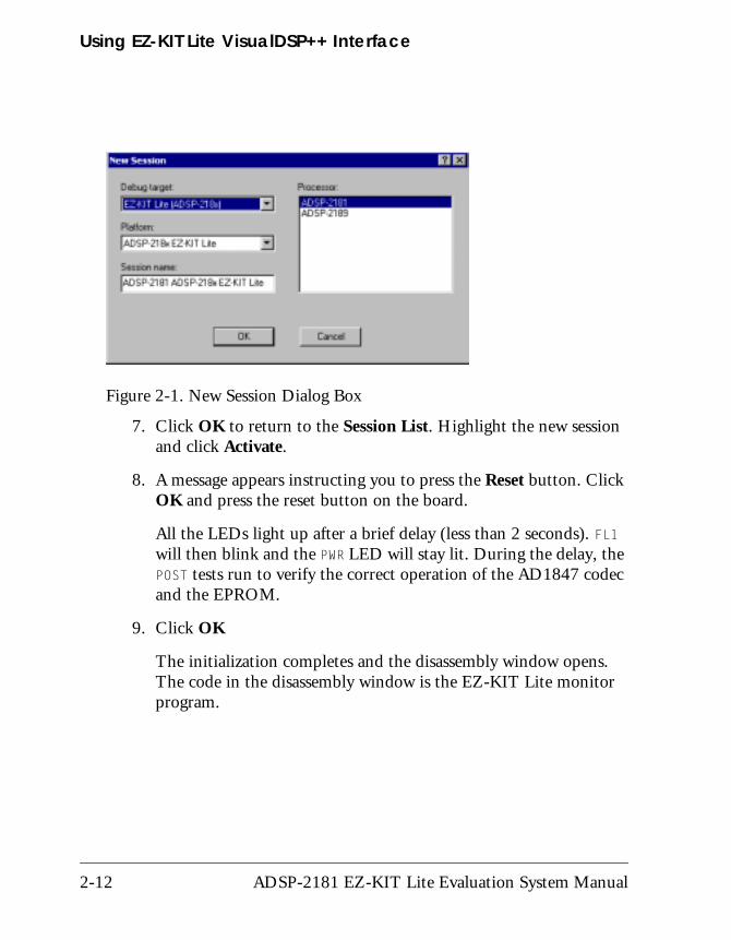
3. The New Session dialog box, shown in Figure 2-1, appears on the screen.
4. In Debug Target, choose EZ-KIT Lite (ADSP-218x).
5. In Processor, choose the appropriate processor, ADSP-2181.
6. Type a new target name in Session Name or accept the default name.
ADSP-2181 EZ-KIT Lite Evaluation System Manual 2-11
Using EZ-KIT Lite VisualDSP++ Interface
7. Click OK to return to the Session List. Highlight the new session and click Activate.
8. A message appears instructing you to press the Reset button. Click OK and press the reset button on the board.
All the LEDs light up after a brief delay (less than 2 seconds). FL1 will then blink and the PWR LED will stay lit. During the delay, the POST tests run to verify the correct operation of the AD1847 codec and the EPROM.
9. Click OK
The initialization completes and the disassembly window opens. The code in the disassembly window is the EZ-KIT Lite monitor program.
Figure 2-1. New Session Dialog Box
2-12 ADSP-2181 EZ-KIT Lite Evaluation System Manual
Using EZ-KIT LITE Software
Debugging With EZ-KIT LiteThe VisualDSP++ User’s Guide for 16-Bit Processors and online Help con-tains most of the information you need to operate the VisualDSP++ debugger with the EZ-KIT Lite evaluation board. Because the manual was written using a simulator as a target, there are some differences and restric-tions in the debugger operation when connected to a hardware target.
Loading ProgramsBecause you are loading programs into a hardware target, the load process takes a slightly longer period of time then loading in the simulator. Wait for the Load Complete message in the Output window before you attempt any debug activities.
To load a program, use the following procedure:
1. From the File menu, select Load.
The Open a Processor Program dialog box appears.
2. Navigate to the folder where your DSP executable file resides.
The demos supplied with the EZ-KIT Lite are located in the ..\218x\EZ-KITs\2181\Examples subdirectory of your Visu-alDSP++ installation directory.
3. Select the file and click Open.
The file loads and the Load Complete message appears in the Out-put window when the load process has completed.
ADSP-2181 EZ-KIT Lite Evaluation System Manual 2-13
Using EZ-KIT Lite VisualDSP++ Interface
Registers and Memory
To see current values in registers and memory, use the F12 key or the Window, Refresh command.
# Register and memory contents may not be changed while the user program is running.
Setting Breakpoints and Stepping
The debugger automatically inserts breakpoints at the function main(), when the Settings, Run To Main command is checked, and at the _exit instruction.
# Breakpoints set in the last three instructions of a do-loop are allowed, but this causes improper debugger operation.
Resetting EZ-KIT Lite Board
The EZ-KIT Lite board can be reset with the push button switch on the board or with the Debug, Reset command in the debugger. After per-forming a reset, reload any programs you were running. The Debug, Restart command also resets the processor. The processor, however, retains all debug information and memory contents.
The following sequence must be used when starting the debugger:
1. Start VisualDSP++ from the Windows Start menu.
The debugger starts and the Target message Hit Reset Button appears.
2. Press the reset button.
3. Click OK.
# Do not use the reset button while the debugger is open unless the debugger requested to do so.
2-14 ADSP-2181 EZ-KIT Lite Evaluation System Manual
Using EZ-KIT LITE Software
Example ProgramsExample programs are included with the ADSP-2181 EZ-KIT Lite to demonstrate various capabilities of the evaluation board. These programs are installed with the EZ-KIT Lite software and can be found in \…\Visu-alDSP\218x\EZ-KITs\2181\Examples. Please refer to the readme file provided with each example for more information.
# Do not run more than one ADSP-2181 EZ-KIT Lite session in the debugger at any one time. You may run an EZ-KIT Lite session and a simulator or ICE session at the same time or you can open two debugger interfaces to run more than one EZ-KIT Lite session.
ADPCM
This program demonstrates Adaptive Differential Pulse Code Modulation (ADPCM) capabilities. ADPCM consists of a number of real-time speech compression algorithms.
DTMF
This demonstration generates Dual-Tone Multi-Frequency (DTMF) tones, as used in the telephone network for push button signaling. A DTMF tone is composed of two different single frequency tone, one of four row tones added to one of four column tones. Thus, a full implemen-tation of a DTMF standard tone generator can generate 16 different tones (only 12 are commonly used on consumer handsets).
ECHO
This demonstration uses the codec to generate an echo and the four chan-nel DAC to display the taps of the echo canceller.
ADSP-2181 EZ-KIT Lite Evaluation System Manual 2-15
Using EZ-KIT Lite VisualDSP++ Interface
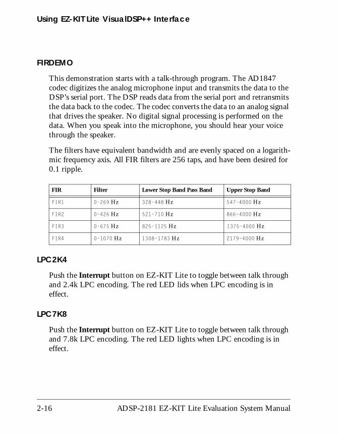
FIRDEMO
This demonstration starts with a talk-through program. The AD1847 codec digitizes the analog microphone input and transmits the data to the DSP’s serial port. The DSP reads data from the serial port and retransmits the data back to the codec. The codec converts the data to an analog signal that drives the speaker. No digital signal processing is performed on the data. When you speak into the microphone, you should hear your voice through the speaker.
The filters have equivalent bandwidth and are evenly spaced on a logarith-mic frequency axis. All FIR filters are 256 taps, and have been desired for 0.1 ripple.
LPC2K4
Push the Interrupt button on EZ-KIT Lite to toggle between talk through and 2.4k LPC encoding. The red LED lids when LPC encoding is in effect.
LPC7K8
Push the Interrupt button on EZ-KIT Lite to toggle between talk through and 7.8k LPC encoding. The red LED lights when LPC encoding is in effect.
FIR Filter Lower Stop Band Pass Band Upper Stop Band
FIR1 0–269 Hz 328–448 Hz 547–4000 Hz
FIR2 0–426 Hz 521–710 Hz 866–4000 Hz
FIR3 0–675 Hz 825–1125 Hz 1375–4000 Hz
FIR4 0–1070 Hz 1308–1783 Hz 2179–4000 Hz
2-16 ADSP-2181 EZ-KIT Lite Evaluation System Manual
Using EZ-KIT LITE Software
PRIMES
This demonstration is a C program that generates the first 20 prime numbers.
ADSP-2181 EZ-KIT Lite Evaluation System Manual 2-17

Using EZ-KIT Lite VisualDSP++ Interface
2-18 ADSP-2181 EZ-KIT Lite Evaluation System Manual
3 EZ-KIT HARDWARE REFERENCE
This chapter discusses the hardware design of the ADSP-2181 EZ-KIT
Lite board. The following topics are covered:• “System Architecture” on page 3-2
Illustrates the configuration of the ADSP-2181 EZ-KIT Lite board.
• “Board Layout” on page 3-3
Shows the location and describes the function of the configuration jumpers, switches, and user LEDs.
• “Connectors” on page 3-5
Shows the location and describes the function of the expansion connectors.
• “Designing EZ-ICE Compatible Systems” on page 3-14
Outlines the ICE emulator theory of operation to aid your EZ-ICE compatible system designs.
ADSP-2181 EZ-KIT Lite Evaluation System Manual 3-1
System Architecture
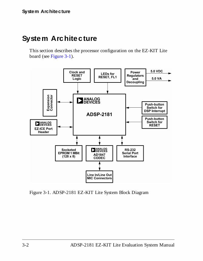
System ArchitectureThis section describes the processor configuration on the EZ-KIT Lite board (see Figure 3-1).
Figure 3-1. ADSP-2181 EZ-KIT Lite System Block Diagram
3-2 ADSP-2181 EZ-KIT Lite Evaluation System Manual
EZ-KIT Hardware Reference
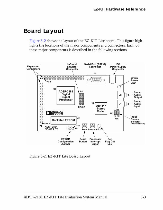
Board LayoutFigure 3-2 shows the layout of the EZ-KIT Lite board. This figure high-lights the locations of the major components and connectors. Each of these major components is described in the following sections.
Figure 3-2. EZ-KIT Lite Board Layout
ADSP-2181 EZ-KIT Lite Evaluation System Manual 3-3
Board Layout
Socketed MemoryThe socketed EPROM provides up to 128k x 8 bits of program storage that can be loaded by the ADSP-2181 processor when it is programmed to boot from the socketed EPROM. After the ADSP-2181 processor is reset, the BDMA feature is used to load the first 32 words of program memory from the byte memory space. Program execution is held off until all 32 words are loaded. Refer to the ADSP-218x DSP Hardware Reference and the ADSP-2181 DSP Microcomputer Data Sheet for more information on program booting and processor modes.
User LEDsThe D1 LED is a red light emitting diode, which is controlled by the FL1 output of the ADSP-2181 processor. Software can control the state of this indicator by writing to an internal register.
The D2 LED is a green light emitting diode, which is on whenever the board has power.
SwitchesThe S1 switch is the reset push button switch. Pushing this button causes the ADSP-2181 processor and the AD1847 codec to enter the hardware reset state and remain there until it is released. The switch outputs are de-bounced electronically to prevent multiple transitions due to mechani-cal contact bounce.
The S2 switch is the interrupt push button switch. Pushing this button causes the ADSP-2181 to receive an IRQE interrupt input. The processor then executes the current IRQE interrupt handler software if the interrupt is enabled and the IRQE interrupt vector is in place. The interrupt switch output is de-bounced electronically to prevent multiple interrupts due to mechanical contact bounce.
3-4 ADSP-2181 EZ-KIT Lite Evaluation System Manual
EZ-KIT Hardware Reference
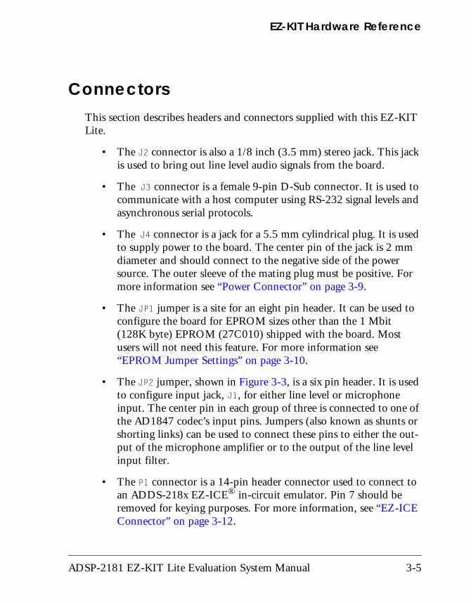
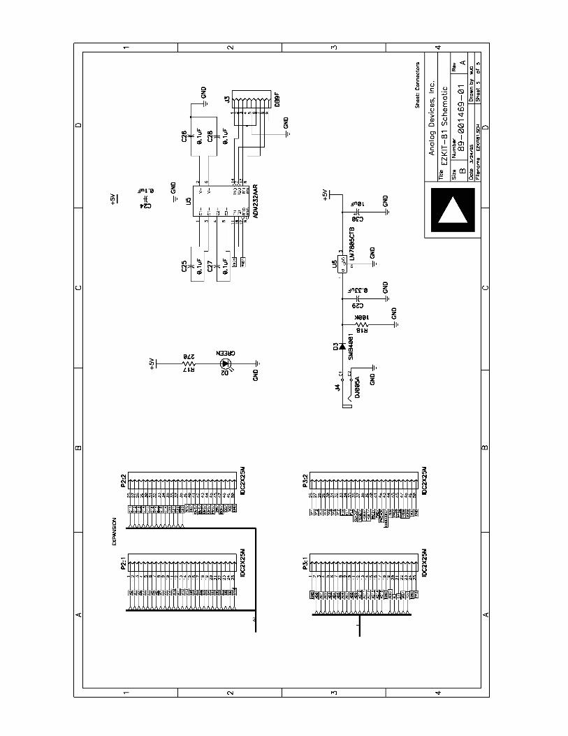
ConnectorsThis section describes headers and connectors supplied with this EZ-KIT Lite.
• The J2 connector is also a 1/8 inch (3.5 mm) stereo jack. This jack is used to bring out line level audio signals from the board.
• The J3 connector is a female 9-pin D-Sub connector. It is used to communicate with a host computer using RS-232 signal levels and asynchronous serial protocols.
• The J4 connector is a jack for a 5.5 mm cylindrical plug. It is used to supply power to the board. The center pin of the jack is 2 mm diameter and should connect to the negative side of the power source. The outer sleeve of the mating plug must be positive. For more information see “Power Connector” on page 3-9.
• The JP1 jumper is a site for an eight pin header. It can be used to configure the board for EPROM sizes other than the 1 Mbit (128K byte) EPROM (27C010) shipped with the board. Most users will not need this feature. For more information see “EPROM Jumper Settings” on page 3-10.
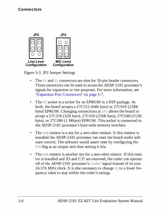
• The JP2 jumper, shown in Figure 3-3, is a six pin header. It is used to configure input jack, J1, for either line level or microphone input. The center pin in each group of three is connected to one of the AD1847 codec’s input pins. Jumpers (also known as shunts or shorting links) can be used to connect these pins to either the out-put of the microphone amplifier or to the output of the line level input filter.
• The P1 connector is a 14-pin header connector used to connect to an ADDS-218x EZ-ICE® in-circuit emulator. Pin 7 should be removed for keying purposes. For more information, see “EZ-ICE Connector” on page 3-12.
ADSP-2181 EZ-KIT Lite Evaluation System Manual 3-5
Connectors
• The P2 and P3 connectors are sites for 50-pin header connectors. These connectors can be used to access the ADSP-2181 processor’s signals for expansion or test purposes. For more information, see “Expansion Port Connectors” on page 3-7.
• The U2 socket is a socket for an EPROM in a DIP package. As built, the board accepts a 27C512 (64K byte) or 27C010 (128K byte) EPROM. Changing connections at JP1 allows the board to accept a 27C256 (32K byte), 27C020 (256K byte), 27C040 (512K byte), or 27C080 (1 Mbyte) EPROM. This socket is connected to the ADSP-2181 processor’s byte-wide memory interface.
• The R28 resistor is a site for a zero-ohm resistor. It this resistor is installed the ADSP-2181 processor can reset the board under soft-ware control. The software would assert reset by configuring the PF0 flag as an output and then setting it low.
• The R29 resistor is another site for a zero-ohm resistor. If this resis-tor is installed and X3 and C37 are removed, the codec can operate off of the ADSP-2181 processor’s CLKOUT signal instead of its own 24.576 MHz clock. It is also necessary to change X1 to a lower fre-quency value to stay within the codec’s ratings.
Figure 3-3. JP2 Jumper Settings
3-6 ADSP-2181 EZ-KIT Lite Evaluation System Manual
EZ-KIT Hardware Reference
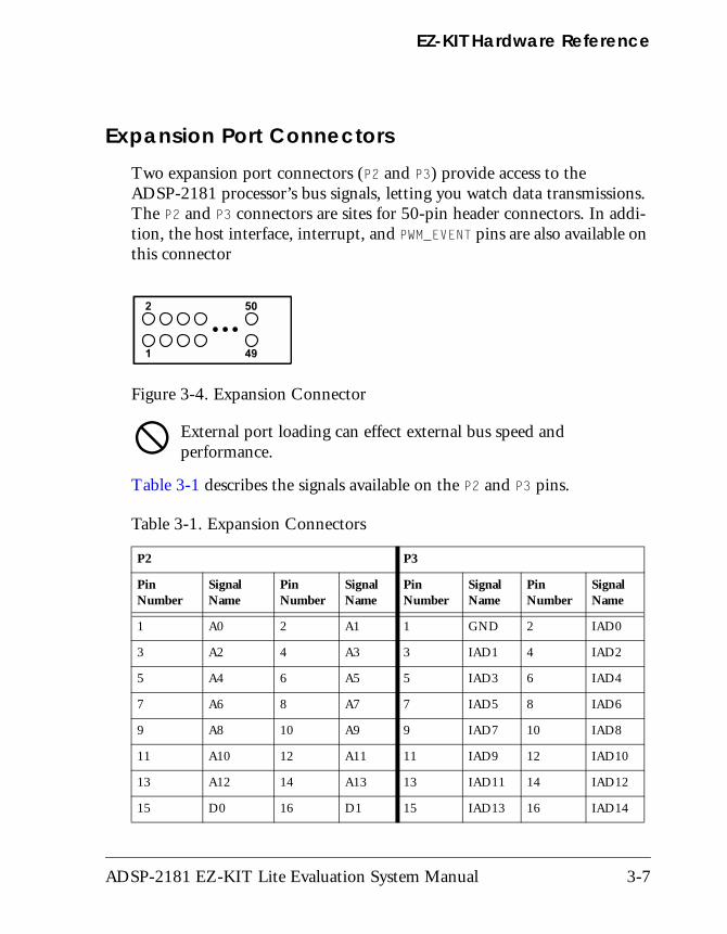
Expansion Port ConnectorsTwo expansion port connectors (P2 and P3) provide access to the ADSP-2181 processor’s bus signals, letting you watch data transmissions. The P2 and P3 connectors are sites for 50-pin header connectors. In addi-tion, the host interface, interrupt, and PWM_EVENT pins are also available on this connector
# External port loading can effect external bus speed and performance.
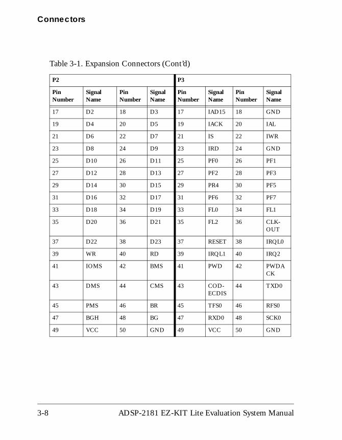
Table 3-1 describes the signals available on the P2 and P3 pins.
Figure 3-4. Expansion Connector
Table 3-1. Expansion Connectors
P2 P3
Pin Number
Signal Name
Pin Number
Signal Name
Pin Number
Signal Name
Pin Number
Signal Name
1 A0 2 A1 1 GND 2 IAD0
3 A2 4 A3 3 IAD1 4 IAD2
5 A4 6 A5 5 IAD3 6 IAD4
7 A6 8 A7 7 IAD5 8 IAD6
9 A8 10 A9 9 IAD7 10 IAD8
11 A10 12 A11 11 IAD9 12 IAD10
13 A12 14 A13 13 IAD11 14 IAD12
15 D0 16 D1 15 IAD13 16 IAD14
ADSP-2181 EZ-KIT Lite Evaluation System Manual 3-7
Connectors
17 D2 18 D3 17 IAD15 18 GND
19 D4 20 D5 19 IACK 20 IAL
21 D6 22 D7 21 IS 22 IWR
23 D8 24 D9 23 IRD 24 GND
25 D10 26 D11 25 PF0 26 PF1
27 D12 28 D13 27 PF2 28 PF3
29 D14 30 D15 29 PR4 30 PF5
31 D16 32 D17 31 PF6 32 PF7
33 D18 34 D19 33 FL0 34 FL1
35 D20 36 D21 35 FL2 36 CLK-OUT
37 D22 38 D23 37 RESET 38 IRQL0
39 WR 40 RD 39 IRQL1 40 IRQ2
41 IOMS 42 BMS 41 PWD 42 PWDACK
43 DMS 44 CMS 43 COD-ECDIS
44 TXD0
45 PMS 46 BR 45 TFS0 46 RFS0
47 BGH 48 BG 47 RXD0 48 SCK0
49 VCC 50 GND 49 VCC 50 GND
Table 3-1. Expansion Connectors (Cont’d)
P2 P3
Pin Number
Signal Name
Pin Number
Signal Name
Pin Number
Signal Name
Pin Number
Signal Name
3-8 ADSP-2181 EZ-KIT Lite Evaluation System Manual
EZ-KIT Hardware Reference
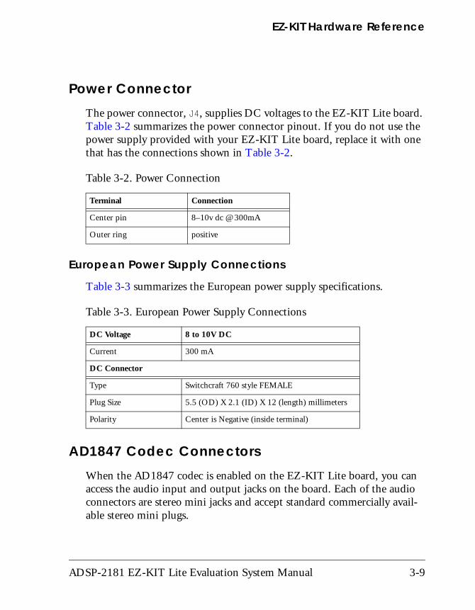
Power ConnectorThe power connector, J4, supplies DC voltages to the EZ-KIT Lite board. Table 3-2 summarizes the power connector pinout. If you do not use the power supply provided with your EZ-KIT Lite board, replace it with one that has the connections shown in Table 3-2.
European Power Supply Connections
Table 3-3 summarizes the European power supply specifications.
AD1847 Codec Connectors When the AD1847 codec is enabled on the EZ-KIT Lite board, you can access the audio input and output jacks on the board. Each of the audio connectors are stereo mini jacks and accept standard commercially avail-able stereo mini plugs.
Table 3-2. Power Connection
Terminal Connection
Center pin 8–10v dc @ 300mA
Outer ring positive
Table 3-3. European Power Supply Connections
DC Voltage 8 to 10V DC
Current 300 mA
DC Connector
Type Switchcraft 760 style FEMALE
Plug Size 5.5 (OD) X 2.1 (ID) X 12 (length) millimeters
Polarity Center is Negative (inside terminal)
ADSP-2181 EZ-KIT Lite Evaluation System Manual 3-9
Connectors
The Microphone/Line_in Input jack connects to the LINE_IN_L (left) and LINE_IN_R (right) pins or the MIC1 and MIC2 of the AD1847 SoundPort Stereo codec, depending on the setting of jumpers JP2.
The LINE Output jack connects to the left (L) LINE_OUT and right (R) LINE_OUT pins of the codec.
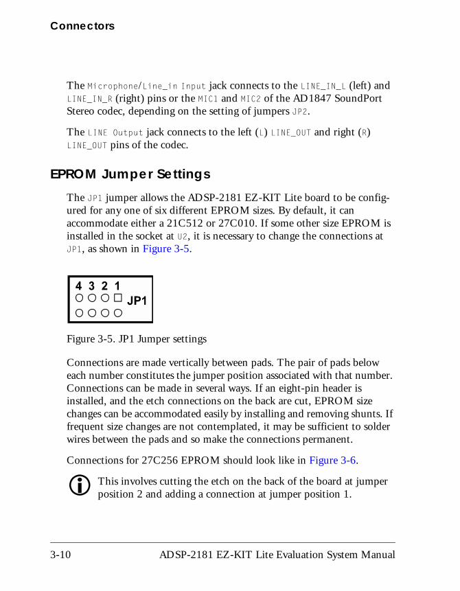
EPROM Jumper SettingsThe JP1 jumper allows the ADSP-2181 EZ-KIT Lite board to be config-ured for any one of six different EPROM sizes. By default, it can accommodate either a 21C512 or 27C010. If some other size EPROM is installed in the socket at U2, it is necessary to change the connections at JP1, as shown in Figure 3-5.
Connections are made vertically between pads. The pair of pads below each number constitutes the jumper position associated with that number. Connections can be made in several ways. If an eight-pin header is installed, and the etch connections on the back are cut, EPROM size changes can be accommodated easily by installing and removing shunts. If frequent size changes are not contemplated, it may be sufficient to solder wires between the pads and so make the connections permanent.
Connections for 27C256 EPROM should look like in Figure 3-6.
" This involves cutting the etch on the back of the board at jumper position 2 and adding a connection at jumper position 1.
Figure 3-5. JP1 Jumper settings
3-10 ADSP-2181 EZ-KIT Lite Evaluation System Manual
EZ-KIT Hardware Reference
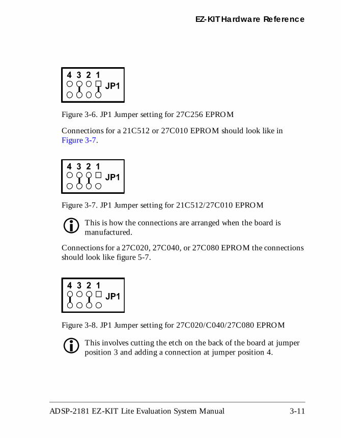
Connections for a 21C512 or 27C010 EPROM should look like in Figure 3-7.
" This is how the connections are arranged when the board is manufactured.
Connections for a 27C020, 27C040, or 27C080 EPROM the connections should look like figure 5-7.
" This involves cutting the etch on the back of the board at jumper position 3 and adding a connection at jumper position 4.
Figure 3-6. JP1 Jumper setting for 27C256 EPROM
Figure 3-7. JP1 Jumper setting for 21C512/27C010 EPROM
Figure 3-8. JP1 Jumper setting for 27C020/C040/27C080 EPROM
ADSP-2181 EZ-KIT Lite Evaluation System Manual 3-11
Connectors
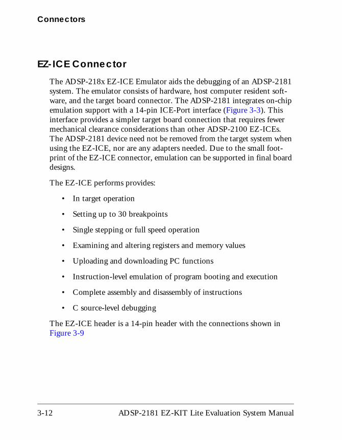
EZ-ICE ConnectorThe ADSP-218x EZ-ICE Emulator aids the debugging of an ADSP-2181 system. The emulator consists of hardware, host computer resident soft-ware, and the target board connector. The ADSP-2181 integrates on-chip emulation support with a 14-pin ICE-Port interface (Figure 3-3). This interface provides a simpler target board connection that requires fewer mechanical clearance considerations than other ADSP-2100 EZ-ICEs. The ADSP-2181 device need not be removed from the target system when using the EZ-ICE, nor are any adapters needed. Due to the small foot-print of the EZ-ICE connector, emulation can be supported in final board designs.
The EZ-ICE performs provides:
• In target operation
• Setting up to 30 breakpoints
• Single stepping or full speed operation
• Examining and altering registers and memory values
• Uploading and downloading PC functions
• Instruction-level emulation of program booting and execution
• Complete assembly and disassembly of instructions
• C source-level debugging
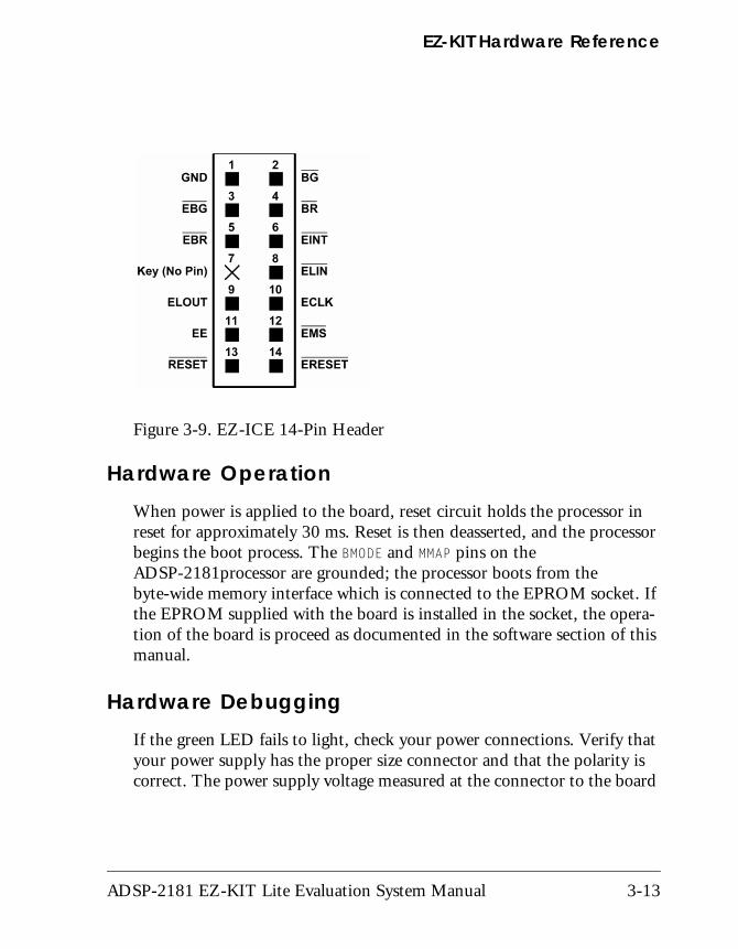
The EZ-ICE header is a 14-pin header with the connections shown in Figure 3-9
3-12 ADSP-2181 EZ-KIT Lite Evaluation System Manual
EZ-KIT Hardware Reference
Hardware OperationWhen power is applied to the board, reset circuit holds the processor in reset for approximately 30 ms. Reset is then deasserted, and the processor begins the boot process. The BMODE and MMAP pins on the ADSP-2181processor are grounded; the processor boots from the byte-wide memory interface which is connected to the EPROM socket. If the EPROM supplied with the board is installed in the socket, the opera-tion of the board is proceed as documented in the software section of this manual.
Hardware DebuggingIf the green LED fails to light, check your power connections. Verify that your power supply has the proper size connector and that the polarity is correct. The power supply voltage measured at the connector to the board
Figure 3-9. EZ-ICE 14-Pin Header
ADSP-2181 EZ-KIT Lite Evaluation System Manual 3-13
Designing EZ-ICE Compatible Systems
should be 8V to 10V DC. Also, make sure that there are no objects beneath or on top of the board that may be causing a short circuit. Hit the reset button (S1) if the board appears to be operating improperly.
Designing EZ-ICE Compatible SystemsThis section describes the ADSP-218x family EZ-ICE theory of operation to aid your EZ-ICE compatible system designs.
The hardware consists of a printed circuit board measuring 3.5 inches by 5.5 inches. Assembled onto the printed circuit board are: an ADSP-2181 digital signal processor, a socketed EPROM, an AD1847 codec, and vari-ous support circuits and connectors. The board is a complete signal processing system designed to demonstrate the capabilities of the ADSP-2181 digital signal processor. It can also be used as a platform to develop new applications targeting ADSP-2181 processors.
The EZ-KIT Lite board is an example of a minimum implementation of an ADSP-2181 processor. The socketed EPROM is connected to the pro-cessor via the Byte DMA Port. This interface uses only eight of the twenty-four data lines to carry data (D8 through D15). Eight of the spare data lines (D16 through D23) are used to provide additional address bits. This allows the ADSP-2181 to address up to 32 Mbits (4 Mbytes) of memory. The DSP is configured to boot from the socketed EPROM when RESET is de-asserted or if power is applied to the board.
The AD1847 codec is connected to the DSP via SPORT0. This high speed synchronous serial port carries all of the data, control, and status informa-tion between the DSP and the codec. It is possible to disable the codec if the serial port is to be used for another purpose. The CODECDIS signal available on connector P3 can be used to disable the codec. When this sig-nal is brought low, the codec is disabled and its signals are put in a high impedance state.
3-14 ADSP-2181 EZ-KIT Lite Evaluation System Manual
EZ-KIT Hardware Reference
The SPORT1 pins are used to communicate with the host PC via the RS-232 interface (J3). The Flag In and Flag Out pins carry the receive and transmit data. Software running on the DSP emulates a UART to provide the proper protocol for asynchronous serial communications up to a data rate of 115K bits per second.
ADSP-2181 EZ-KIT Lite Evaluation System Manual 3-15
Designing EZ-ICE Compatible Systems
3-16 ADSP-2181 EZ-KIT Lite Evaluation System Manual
A RESTRICTIONS
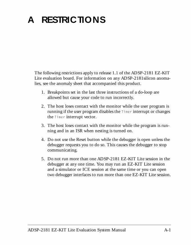
The following restrictions apply to release 1.1 of the ADSP-2181 EZ-KIT
Lite evaluation board. For information on any ADSP-2181silicon anoma-lies, see the anomaly sheet that accompanied this product.1. Breakpoints set in the last three instructions of a do-loop are allowed but cause your code to run incorrectly.
2. The host loses contact with the monitor while the user program is running if the user program disables the Timer interrupt or changes the Timer interrupt vector.
3. The host loses contact with the monitor while the program is run-ning and in an ISR when nesting is turned on.
4. Do not use the Reset button while the debugger is open unless the debugger requests you to do so. This causes the debugger to stop communicating.
5. Do not run more than one ADSP-2181 EZ-KIT Lite session in the debugger at any one time. You may run an EZ-KIT Lite session and a simulator or ICE session at the same time or you can open two debugger interfaces to run more than one EZ-KIT Lite session.
ADSP-2181 EZ-KIT Lite Evaluation System Manual A-1

A-2 ADSP-2181 EZ-KIT Lite Evaluation System Manual
B BILL OF MATERIALS
r
Ref
eren
ce
Qua
ntit
y
Des
crip
tion
Man
ufac
ture
Ref
eren
ce
Des
ign
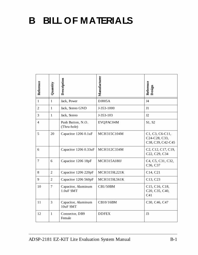
1 1 Jack, Power DJ005A J4
2 1 Jack, Stereo GND J-353-1000 J1
3 1 Jack, Stereo J-353-103 J2
4 Push Button, N.O. (Thru-hole)
EVQPAC04M S1, S2
5 20 Capacitor 1206 0.1uF MCH315C104M C1, C3, C6-C11, C24-C28, C33, C38, C39, C42-C45
6 Capacitor 1206 0.33uF MCH312C334M C2, C12, C17, C19, C22, C29, C34
7 6 Capacitor 1206 18pF MCH315A180J C4, C5, C31, C32, C36, C37
8 2 Capacitor 1206 220pF MCH315SL221K C14, C21
9 2 Capacitor 1206 560pF MCH315SL561K C13, C23
10 7 Capacitor, Aluminum 1.0uF SMT
CB1/50BM C15, C16, C18, C20, C35, C40, C41
11 3 Capacitor, Aluminum 10uF SMT
CB10/16BM C30, C46, C47
12 1 Connector, DB9 Female
DDFEX J3
ADSP-2181 EZ-KIT Lite Evaluation System Manual B-1
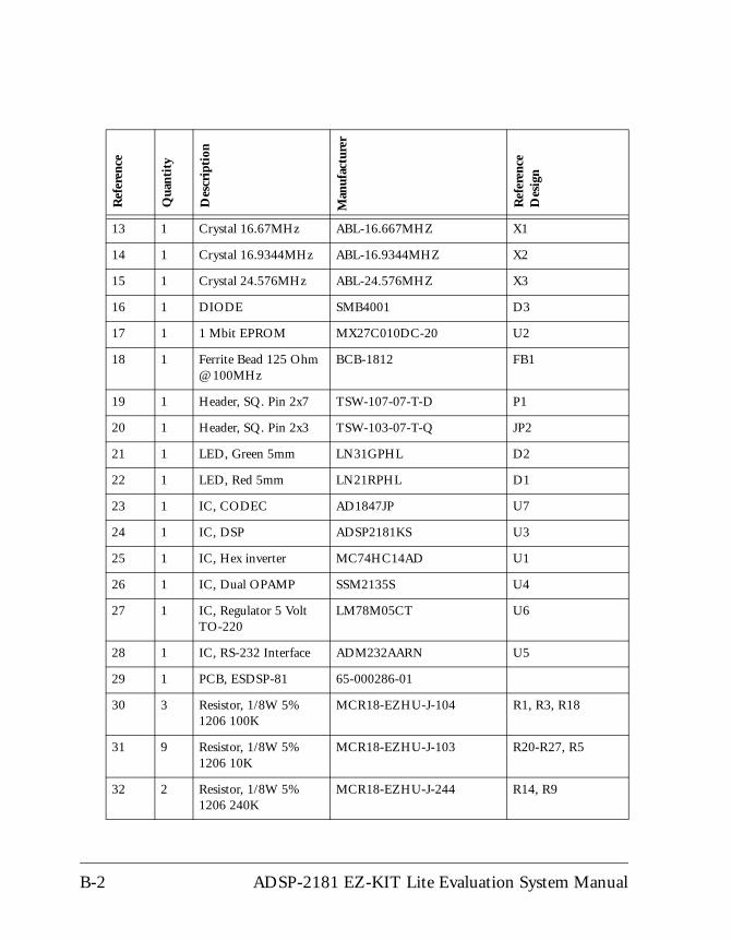
13 1 Crystal 16.67MHz ABL-16.667MHZ X1
14 1 Crystal 16.9344MHz ABL-16.9344MHZ X2
15 1 Crystal 24.576MHz ABL-24.576MHZ X3
16 1 DIODE SMB4001 D3
17 1 1 Mbit EPROM MX27C010DC-20 U2
18 1 Ferrite Bead 125 Ohm @ 100MHz
BCB-1812 FB1
19 1 Header, SQ. Pin 2x7 TSW-107-07-T-D P1
20 1 Header, SQ. Pin 2x3 TSW-103-07-T-Q JP2
21 1 LED, Green 5mm LN31GPHL D2
22 1 LED, Red 5mm LN21RPHL D1
23 1 IC, CODEC AD1847JP U7
24 1 IC, DSP ADSP2181KS U3
25 1 IC, Hex inverter MC74HC14AD U1
26 1 IC, Dual OPAMP SSM2135S U4
27 1 IC, Regulator 5 Volt TO-220
LM78M05CT U6
28 1 IC, RS-232 Interface ADM232AARN U5
29 1 PCB, ESDSP-81 65-000286-01
30 3 Resistor, 1/8W 5% 1206 100K
MCR18-EZHU-J-104 R1, R3, R18
31 9 Resistor, 1/8W 5% 1206 10K
MCR18-EZHU-J-103 R20-R27, R5
32 2 Resistor, 1/8W 5% 1206 240K
MCR18-EZHU-J-244 R14, R9
Ref
eren
ce
Qua
ntit
y
Des
crip
tion
Man
ufac
ture
r
Ref
eren
ce
Des
ign
B-2 ADSP-2181 EZ-KIT Lite Evaluation System Manual
Bill Of Materials
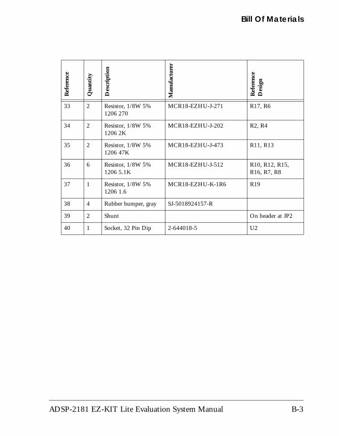
33 2 Resistor, 1/8W 5% 1206 270
MCR18-EZHU-J-271 R17, R6
34 2 Resistor, 1/8W 5% 1206 2K
MCR18-EZHU-J-202 R2, R4
35 2 Resistor, 1/8W 5% 1206 47K
MCR18-EZHU-J-473 R11, R13
36 6 Resistor, 1/8W 5% 1206 5.1K
MCR18-EZHU-J-512 R10, R12, R15, R16, R7, R8
37 1 Resistor, 1/8W 5% 1206 1.6
MCR18-EZHU-K-1R6 R19
38 4 Rubber bumper, gray SJ-5018924157-R
39 2 Shunt On header at JP2
40 1 Socket, 32 Pin Dip 2-644018-5 U2
Ref
eren
ce
Qua
ntit
y
Des
crip
tion
Man
ufac
ture
r
Ref
eren
ce
Des
ign
ADSP-2181 EZ-KIT Lite Evaluation System Manual B-3

B-4 ADSP-2181 EZ-KIT Lite Evaluation System Manual
I INDEX
A microphone input, 2-16
AD1847 codec, -viiiclock, 3-6connectors, 3-9converting to analog, 2-16dual analog front end, 2-9hardware reset, 3-4initializing, 2-7, 2-9transmissions, 2-9
ADPCM capabilities, 2-15ADSP-2181 EZ-KIT Lite
debugging, 2-13default settings, 2-3features, -vii, -viiihardware restrictions, A-1license restrictions, 2-2memory map, 2-2resetting board, 2-5setting hardware, 1-4system architecture, 3-2VisualDSP++ interface, 2-10
ADSP-2181 processorinternal memory restrictions, 2-2
analogaudio interface, -viii
see also AD1847 codecinput, -viii
output, -viiiassembly, 3-12asynchronous pin (FL1), 2-4audio
configuring board, 1-5input, -ix, 3-9output, -ix, 3-9
Bbaud rate, 2-6, 2-7BDMA, 3-4bill of materials, B-1BMODE pin, 3-13board
architecture, 3-2layout, 3-3
bootingADSP-2181processor, 3-4programs, 3-12
breakpoints, 2-14restrictions, A-1
CCLKOUT signal, 3-6CODECDIS signal, 2-5, 3-14codecs
ADSP-2181 EZ-KIT Lite Evaluation System Manual I-1
INDEX
see AD1847 codeccomm port, 1-4command processing, 2-8configuring board for audio, 1-5connecting board, 1-4connector map, 3-3connectors
J1 (input jack), 3-5J2 (stereo jack), 3-5J3 (RS-232), 1-4, 3-5, 3-15J4 (power jack), 1-4, 3-5JP1 (EPROM) jumper, 3-5, 3-6, 3-10JP2 header, 3-5P1 header, 3-5P2 (expansion), 3-6, 3-7P3 (expansion), 2-5, 3-6, 3-7R28 resistor, 3-6R29 resistor, 3-6
conventions, manual, -xviicopyright information, 1-iicustomer support, -xi
DDAC, 2-15data
clock, 2-9transmissions, 3-7, 3-15
DEBUG command, 2-5debugger, 2-6, 2-11, 2-14, A-1debugging, 2-9, 2-13, 3-12default settings, 2-3developing programs, 2-10development cycle, 2-10DIP package, 3-6
disassembly, 3-12DMA port, 3-14DTMF tones, 2-15
Eecho canceller, 2-15electrostatic discharge, 1-2, 1-4emulation, 3-12
port, -viienvironment, -viiiEPROM, -viii, -ix, 2-6, 3-4, 3-6
jumper (JP1), 3-10sizes, 3-10socket, 3-13
European power specifications, 3-9example programs, 2-15expansion
connectors, -viii, -ix, 3-6, 3-7port, 3-7
externalclock, -viiiinterrupt, 2-4port, 3-7
EZ-ICE(in-circuit emulator), -ix, 3-12compatible systems, 3-14header, 3-12
FFL1 pin, 2-4, 3-4flag IO pin, 2-4, 3-15frequency tone, 2-15
I-2 ADSP-2181 EZ-KIT Lite Evaluation System Manual
INDEX
Hhalt loop, 2-7hardware
debugging, 3-13design, 3-1installation, 1-5reset, 3-13restrictions, A-1target, 2-13
headerconnectors, 3-7EZ-ICE, 3-12
Help, online, -xvhost control, -ix
IICE
port interface, 3-12session, 2-11, A-1
ICNTL register, 2-4IMASK registers, 2-4input jack, 3-10inserting breakpoints, 2-14installation tasks, 1-3installing
hardware, 1-5licence, 1-6VisualDSP++ and EZ-KIT Lite
software, 1-5instruction rate, -viiiinternal RAM, 2-6interrupt
disabled, 2-4nesting, 2-4
request, 2-9switch, 3-4vector, 2-4, 2-8, A-1
IOdevices, 2-3
IRQE external interrupt, 2-4, 3-4
JJ2 (stereo jack), 3-5J3 (RS-232) connector, 3-5, 3-15J4 (power jack) connector, 3-5JP1 jumper, 3-5, 3-6, 3-10JP2 jumper, 3-5jumpers, -viii
LLEDs, 1-4
D1 (red emitting diode), 3-4D2 (green emitting diode), 3-4power LED, 1-4
licenseinstallation, 1-6restrictions, 2-2
limited warranty, 1-iiline level
inputs, -viiioutputs, -viii
loading programs, 2-13LPC encoding, 2-16
Mmemory
checking, 2-6, 2-14, 3-12map, 2-2
ADSP-2181 EZ-KIT Lite Evaluation System Manual I-3
INDEX
microphone inputs, -viiiMMAP pins, 3-13monitor program, -vii, -ix, 2-4, 2-6, 2-7,
2-8, 2-9, A-1
Ooutput jack, 3-10
PP1 header, 3-5P2, expansion connector, 3-6P3, expansion connector, 3-6package contents, 1-2PF0 flag, 3-6POST
routines, 2-5, 2-6power
cable, 1-2connecting, 3-13jack (J4), 3-5, 3-9source, -viii, 3-5specifications, 3-9supply, 1-2, 3-13
powering board, 3-13prime numbers, 2-17program
booting, 3-12memory, 2-2size, 2-2
programmable LEDssee LEDs
push buttons, -viii, 3-4S1 (reset) switch, 2-14, 3-4S2 (external ISR), 2-4
S2 (external ISR) switch, 3-4PWM_EVENT pins, 3-7
RR28 resistor, 3-6R29 resistor, 3-6read/write memory, 2-7register checking, 2-14, 3-12reset, 2-5, 3-4, 3-6, 3-13
button (S1), 3-14, A-1types, 2-5
RESET command, 2-5resetting EZ-KIT Lite, 2-14Restart command, 2-14RS-232
cable, 1-2, 1-4interface, -viii, 2-5
RX interrupt, 2-9
Sserial numbers, 1-6serial ports, -vii, -ix, 1-2, 2-5, 2-16setting
breakpoints, 2-14, 3-12hardware, 1-4
simulator session, 2-11SINGLE STEP command, 2-8socketed memory, 3-4software
breakpoints, 2-9installation, 1-5
speech compression algorithms, 2-15SPORT0 port, 2-5, 2-9, 3-14SPORT0 TX interrupt, 2-7, 2-9
I-4 ADSP-2181 EZ-KIT Lite Evaluation System Manual
INDEX
SPORT1 port, 2-5, 3-15SRAM, 2-2standard memory checks, 2-6starting Visual DSP++, 2-11stepping, 2-14, 3-12stereo mini jacks, 3-9switches, 3-4
see also push buttonssynchronization pulse, 2-9synchronous serial port, 3-14system
architecture, 3-2EZ-ICE compatible, 3-14requirements, PC, 1-3
Ttesting
memory, 2-6UART, 2-6
Timer ISR, 2-4, 2-8, A-1transmitted loop back routine, 2-6
TX interrupt, 2-9
UU2 socket, 3-6UART, 2-5
baud rate, 2-7ISR, 2-8protocol, 3-15test protocol, 2-6
user LEDssee LEDs
VVisualDSP++, 1-2
documentation, -xviinstallation, 1-5interface, 2-10license, 1-6online Help, -xvrequirements, 1-3
ADSP-2181 EZ-KIT Lite Evaluation System Manual I-5
INDEX
I-6 ADSP-2181 EZ-KIT Lite Evaluation System Manual