ademco k3522
DESCRIPTION
ADEMCO K3522TRANSCRIPT

������������������ ����������������������
�������������������������� ������������
����������
*
FIRE FIRE
PULL
K3522 3/99
– 2 –
TABLE OF CONTENTS
SYSTEM OVERVIEW ....................................4General .......................................................4A Partitioned System ..................................4Zones..........................................................5Fire Protection ............................................5Burglary Protection .....................................5Alarms.........................................................6Memory of Alarm ........................................6Speed Key (Macros) ...................................6Using Schedules.........................................7Device Timers.............................................7To Access Another Partition (GOTOCommand) ..................................................7Master Keypad Operation...........................8Self-Help Feature........................................8Phone Access & Voice ResponseCapability ....................................................8
ABOUT THE KEYPADS...............................10General .....................................................10The Alpha Keypad ....................................10
FUNCTIONS OF THE KEYPAD...................11ENTRY/EXIT DELAYS.................................14
General Information ..................................14SECURITY CODES & AUTHORITY
LEVELS ....................................................15General Information ..................................15Duress Code.............................................15Quick Arming ............................................15Authority Levels ........................................16General Rules on Authority Levels andChanges ...................................................17To Exit User Edit Mode.............................18To Add a User...........................................18To Change a User's Code ........................20To Delete a User.......................................21
ACCESSING OTHER PARTITIONS............22To Access Another Partition .....................22Global Arming ...........................................22Master Keypad Operation.........................23Common Lobby Operation........................25
How User Codes Affect the CommonLobby ........................................................26
CHECKING FOR OPEN ZONES .................28
Using the ✴ Ready Key ........................28
DISPLAYING ALL ZONEDESCRIPTORS........................................29
Using the ✴ Ready Key ........................29
BYPASSING PROTECTION ZONES ..........30
Using the 6 Bypass Key.......................30
Quick Bypass............................................31Displaying Bypassed Zones .....................31
ARMING PERIMETER ONLY ......................32
Using the 3 Stay key............................32
ARMING PERIMETER ONLY ......................33
Using the 7 Instant Key........................33
ARMING ALL PROTECTION.......................34
Using the 2 Away Key..........................34
ARMING ALL PROTECTION.......................35
Using the 4 Maximum Key...................35
DISARMING AND SILENCING ALARMS....36
Using the 1 OFF Key ...........................36
Memory of Alarm ......................................36USING THE KEYSWITCH ...........................37
General .....................................................37Arming ......................................................37Disarming..................................................37
CHIME MODE ..............................................38
Using the 9 Key ...................................38
VIEWING CENTRAL STATIONMESSAGES..............................................39General Information ..................................39
PANIC KEYS................................................40Using Panic Keys......................................40
SPEED KEY (MACROS)..............................41
– 3 –
General Information ..................................41Defining.....................................................41Executing ..................................................42
ACCESS DOOR CONTROL ........................43General Information ..................................43
USING #70 RELAY MENU MODE...............44General Information ..................................44
USING SCHEDULES ...................................46Delaying the Closing Time........................46Temporary Open/Close Schedules ..........46Programming Temporary Schedules........47
PROGRAMMING DEVICE TIMERS ............50General Information ..................................50
EVENT LOG PROCEDURES ......................53General Information ..................................53To Display The Event Log ........................53
EVENT LOGGING PROCEDURES(CONTINUED) ..........................................54
TESTING THE SYSTEM..............................55
Using the 5 Test Key ...........................55
Testing Your System ................................56FIRE ALARM SYSTEM................................57
General .....................................................57In Case Of Fire Alarm...............................57Silencing A Fire Alarm ..............................57
Fire Display Lock ......................................58Fire Drill Test (Code + # + 69) ..................58
TROUBLE CONDITIONS.............................60Typical Trouble Displays ..........................60Power Failure............................................62
RECOMMENDATIONS FOR PROPERPROTECTION ..........................................63Recommendations For Smoke AndHeat Detectors..........................................63Recommendations For ProperIntrusion Protection...................................65
EMERGENCY EVACUATION......................66MAINTAINING YOUR SYSTEM ..................67
Taking Care of Your System ....................67Replacing Batteries in WirelessSensors.....................................................67Silencing Low Battery Warning Tonesat the Keypad............................................68Routine Care.............................................68
QUICK GUIDE TO SYSTEMFUNCTIONS.............................................69
SUMMARY OF AUDIBLENOTIFICATION ........................................71
GLOSSARY..................................................72INDEX...........................................................78
– 4 –
System Overview
General
Congratulations on your ownership of an Ademco Partitioned SecuritySystem. You've made a wise decision in choosing it, for it representsthe latest in security protection technology today. Ademco is theworld's largest manufacturer of security systems and millions ofpremises are protected by Ademco systems.
This system offers you three forms of protection: burglary, fire andemergency. To realize the full potential of the system, it is importantthat you feel comfortable in operating it. Your system consists of atleast one keypad that provides full control of system operation,various sensors that provide perimeter and interior burglaryprotection, plus a selected number of strategically placed smoke orcombustion detectors designed to provide early warning in case of fire.
The system uses microcomputer technology to monitor all protectionzones and system status and provides appropriate information fordisplay on the keypad(s) used with the system, and initiatesappropriate alarms. Your system may also have been programmed toautomatically transmit alarm or status messages over the phone linesto a central alarm monitoring station.
A Partitioned System
Simply stated, a partitioned system shares one physical alarm systemamong different users, each with their own requirements. For themost part, you as a user need not know about other users and theirstructure in the system, but from time to time, you may see displaymessages which indicate the system is in use by another user. Do notbe concerned, this is normal. Refer to the Accessing Other Partitionssection for additional information.
– 5 –
System Overview (cont’d)
Zones
Your system's sensing devices have been assigned to various zones.For example, the sensing device on your Entry/Exit door may havebeen assigned to zone 001, sensing devices on windows in the masterbedroom to zone 002, and so on. These numbers will appear on thedisplay, along with an alpha descriptor for that zone (if programmed),when an alarm or trouble condition occurs.
Fire Protection
The fire protection portion of your security system (if used) is alwayson and will sound an alarm if a fire condition is detected. Refer to theFire Alarm System section for important information concerning fireprotection, smoke detectors and planning emergency exit routes fromyour house.
Burglary Protection
The burglary protection portion of your system must be turned on orarmed before it will sense burglary alarm conditions. Your systemprovides four modes of burglary protection: Stay, Away, Instant andMaximum, and even allows you to bypass selected zones of protectionwhile leaving the rest of the system armed. The system also provides aChime mode, for alerting users to the opening and closing of doors andwindows while the system is disarmed. Refer to the other sections ofthis manual for procedures for using these features.
– 6 –
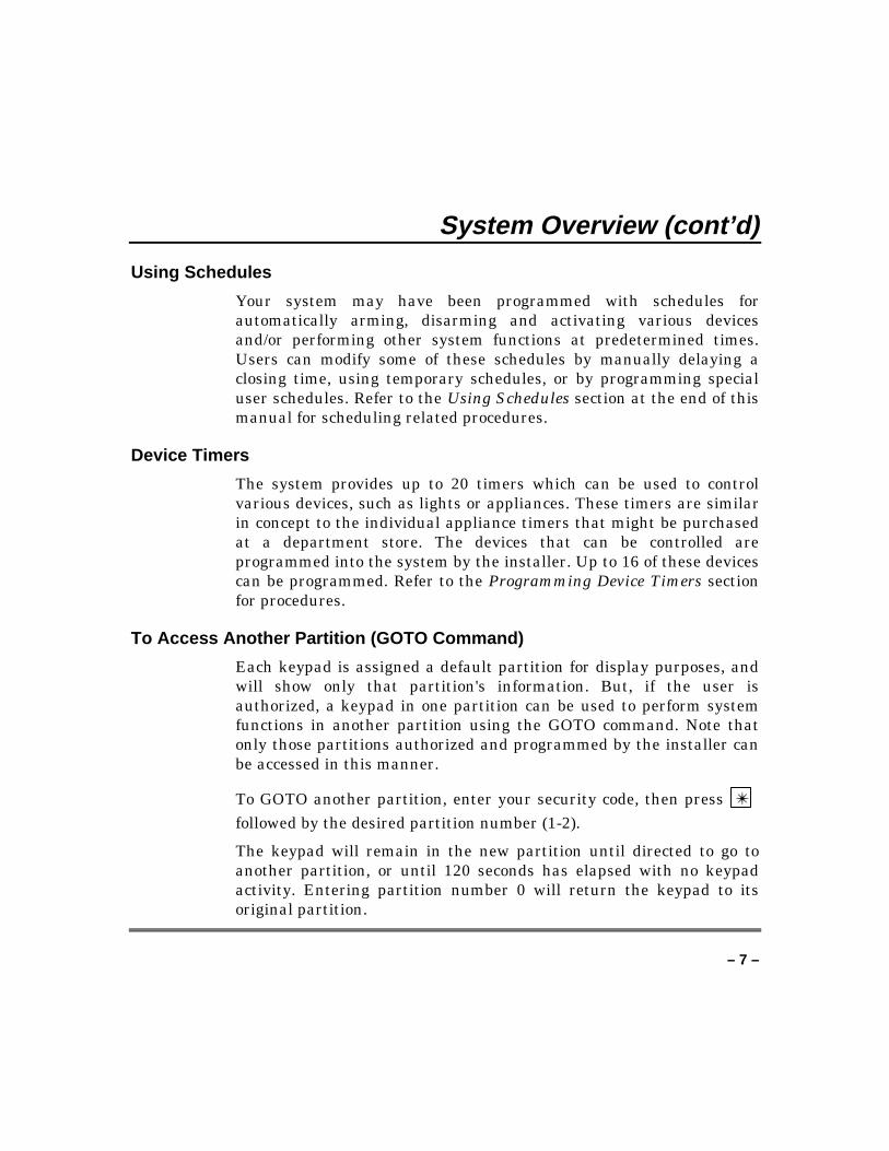
System Overview (cont’d)The following table lists the four different arming modes and theresults of each.
Features For Each Arming ModeArming Mode Exit
DelayEntryDelay
PerimeterArmed
InteriorArmed
AWAY Yes Yes Yes YesSTAY Yes Yes Yes NoINSTANT Yes No Yes NoMAXIMUM Yes No Yes Yes
Alarms
When an alarm occurs, both the keypad and external sounders willsound, and the keypad will display the zone(s) causing the alarm. Ifyour system is connected to a central monitoring station, an alarmmessage will also be sent. To stop the alarm sounding, simply disarmthe system.
Memory of Alarm
When an alarm condition occurs, the keypad displays the number(s) ofthe zone(s) that caused the problem, and displays the type of alarm(e.g., Fire, Alarm). It remains displayed until it is cleared bydisarming the system (see Disarming and Silencing Alarms section).
Speed Key (Macros)
The system can store a string of up to 32 keystrokes, which can beactivated anytime by simply pressing the A, B, C, or D keys. Thisfeature can be used to make it easy to perform a complicatedprocedure (such as going to another partition to bypass a zone), or itcan be used to simplify an everyday, repeated procedure. Refer to theSpeed Key (Macros) section for procedures for using this feature.
– 7 –
System Overview (cont’d)
Using Schedules
Your system may have been programmed with schedules forautomatically arming, disarming and activating various devicesand/or performing other system functions at predetermined times.Users can modify some of these schedules by manually delaying aclosing time, using temporary schedules, or by programming specialuser schedules. Refer to the Using Schedules section at the end of thismanual for scheduling related procedures.
Device Timers
The system provides up to 20 timers which can be used to controlvarious devices, such as lights or appliances. These timers are similarin concept to the individual appliance timers that might be purchasedat a department store. The devices that can be controlled areprogrammed into the system by the installer. Up to 16 of these devicescan be programmed. Refer to the Programming Device Timers sectionfor procedures.
To Access Another Partition (GOTO Command)
Each keypad is assigned a default partition for display purposes, andwill show only that partition's information. But, if the user isauthorized, a keypad in one partition can be used to perform systemfunctions in another partition using the GOTO command. Note thatonly those partitions authorized and programmed by the installer canbe accessed in this manner.
To GOTO another partition, enter your security code, then press ✴
followed by the desired partition number (1-2).
The keypad will remain in the new partition until directed to go toanother partition, or until 120 seconds has elapsed with no keypadactivity. Entering partition number 0 will return the keypad to itsoriginal partition.
– 8 –
System Overview (cont’d)
Master Keypad Operation
A master keypad is one on which the status of both partitions isdisplayed simultaneously. A user can get more information about a
certain partition by simply entering ✴ + the desired partitionnumber (1-2). To log on to the master partition (3) using the GOTOcommand, a user must have access to all partitions.
Self-Help Feature
Abbreviated user's instructions are built into the system that can beeasily viewed on the alpha keypad's message display screen. Thisfeature will prove particularly useful if this manual is notconveniently accessible when you need to perform a system procedurewith which you are not familiar.
To view the abbreviated instructions:
Simply press and hold down the function key of interest until thedescription starts to appear (about five seconds) and then release it.
Refer to the Functions Of The Keypad section for descriptions ofeach key function.
Phone Access & Voice Response Capability
Your system may include a 4285 or 4286 VIP module that will permityou to access the system via a touch-tone phone, either on-premises orby call-in when away. The phone access feature will enable you to dothe following:
• Receive synthesized voice messages over the telephone regardingthe status of the security system.
• Arm and disarm the system and perform most function commandsvia the telephone, with voice confirmation provided after eachcommand entry.
– 9 –
System Overview (cont’d)• Control 4204/4204CF relays devices through the #70 Manual Relay
Activation mode.
Complete information regarding the use of this feature is provided in aseparate manual entitled Phone Access User's Guide, whichaccompanies the 4285 or 4286 VIP module.
– 10 –
About The Keypads
General
IMPORTANT: If the keypad beeps rapidly uponentering the premises, it indicates that an alarm has
occurred during your absence. LEAVEIMMEDIATELY and CONTACT THE POLICE
from a nearby safe location.
Your keypads allow you to control all system functions. The keypadsfeature a telephone style (digital) keypad and a Liquid CrystalDisplay (LCD) which shows the nature and location of all occurrences.Keypad display back lighting is programmable to always stay on or tolight only when a key is pressed, then turn off a few minutes later.
The keypads also feature a built-in sounder that will sound duringalarms and troubles. It will also beep during certain system functions,such as during entry/exit delay times, during Chime mode, and whendepressing keys to arm and disarm the system (to acknowledge thekey press). These sounds can be optionally suppressed in some of yourkeypads (so as not to disturb other users of the system). Ask yourinstaller if this has been done.
The Alpha Keypad
Alpha keypads feature a 2-line, 32 character alphanumeric LiquidCrystal Display (LCD) which can display system messages in friendlyEnglish. Abbreviated user's instructions can also be displayed (seeSelf Help paragraph in the System Overview section). These keypadscan also be programmed with custom zone descriptors.
– 11 –
Functions Of The Keypad
READYARMED
PANIC
OFF AWAY STAY
MAX TEST BYPASS
INSTANT CODE CHIME
READY
1 2 3
654
8 97
0* #
A
B
C
D
15
1 25 3
4
6
7
9
10
12
13118
17
14
16
LOCATION OF DEDICATED PANIC KEYS.KEY D USED AS SPEEDKEY (if programmed)
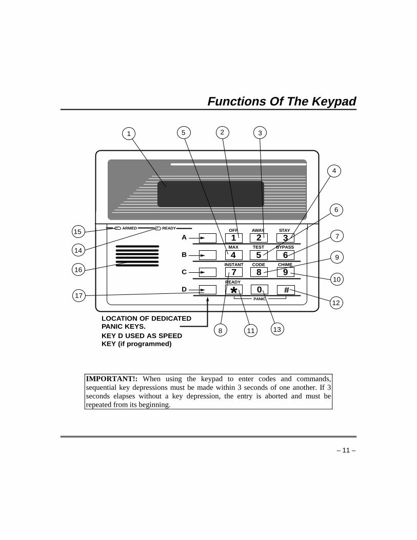
IMPORTANT!: When using the keypad to enter codes and commands,sequential key depressions must be made within 3 seconds of one another. If 3seconds elapses without a key depression, the entry is aborted and must berepeated from its beginning.
– 12 –
Functions Of The Keypad (cont’d)1. ALPHA DISPLAY WINDOW: A
2-line, 32-character Liquid CrystalDisplay (LCD). Displaysprotection point identification andsystem status messages, and userinstructions.
2. OFF KEY: Disarms the burglary
portion of the system, silencesalarms and audible troubleindicators, and clears visual alarmtrouble after the problem has beencorrected.
3. AWAY KEY: Completely arms
both perimeter and interiorburglary protection by sensing anintruder's movements throughprotected interior areas as well asguarding protected doors, windows,etc. Late arrivals can enter throughan entry delay zone without causingan alarm if the system is disarmedbefore the entry delay time expires.
4. STAY KEY: Arms the
perimeter burglary protection,guarding protected doors, windowsand other perimeter protectionpoints, and sounds an alarm if oneis opened. Interior protection is notarmed, which allows movementwithin your house without causing
an alarm. Late arrivals can enterthrough an Entry Delay zone withoutcausing an alarm if the system isdisarmed before the entry delay timeexpires.
5. MAXIMUM KEY: Arms in manner
similar to Away mode, but eliminatesthe entry delay period, thus providingmaximum protection. An alarm willoccur immediately upon opening anyprotection point, including entry delayzones.
6. TEST KEY: Tests the system and
alarm sounder if disarmed.
7. BYPASS KEY: Removes individual
protection zones from being monitoredby the system. Displays previouslybypassed protection zones.
8. INSTANT KEY: Arms in manner
similar to Stay mode, but turns off theentry delay period, offering greatersecurity while inside and notexpecting any late arrivals. An alarmwill occur immediately upon openingany perimeter protection point,including entry delay zones.
9. CODE KEY: Allows the entry of
additional user codes that can begiven to other users of the system.
– 13 –
Functions Of The Keypad (cont’d)
10. CHIME KEY: Turns on & off the
Chime mode. When on, any entrythrough a protected delay orperimeter zone while the system isdisarmed will cause a tone to soundat the keypad(s).
11. READY KEY: When depressed
prior to arming the system, thekeypad will display all openprotection zones within the keypad'shome partition. This key is also usedto display all zone descriptors thathave been programmed for yoursystem, by holding the key down forat least five seconds.
12. # KEY: Permits arming of the
system without use of a securitycode (Quick Arm, if programmed).
13. KEYS 0-9: Used to enter yourindividual security access code(s).
14. POWER/READY INDICATOR:(GREEN) On some keypads, thislights when primary power is on. Ifoff, the system is operating on itsbackup battery power. CALL YOURINSTALLER IMMEDIATELY. Onother types of keypads, lit indicatessystem is ready to be armed, whileunlit indicates system not ready.
15. ARMED INDICATOR: (RED) Litwhen the system has been armed(Stay, Away, Instant or Maximum).
16. INTERNAL SOUNDER: Source ofaudible, internal warning andconfirmation sounds, as well asalarms (see Summary of AudibleNotifications).
17. A-B-C PANIC KEYS: Refer to thePanic Keys section for descriptions ofthese keys.
– 14 –
Entry/Exit Delays
General Information
Your system has preset time delays, known as exit delay and entrydelay. Whenever you arm your system, Exit Delay gives you time toleave through the designated exit door without setting off an alarm.Exit Delay begins immediately after entering any arming command,and applies to all modes of arming protection. If programmed, a slowbeeping will sound throughout the exit delay period.
Entry Delay gives you time to disarm the system when you reenterthrough the designated entrance door. But the system must bedisarmed before the entry delay period ends, or an alarm will occur.The keypad will beep during the entry delay period, reminding you todisarm the system. You can also arm the system with no entry delayat all by using either Instant or Maximum Arming modes. Thesemodes provide greater security while on the premises or while awayfor extended periods of time. See your installer for your delay times.
– 15 –
Security Codes & Authority Levels
General Information
At the time of installation, you were assigned an authority level and apersonal four-digit security code, known only to you and yours. Thesecurity code must be entered when arming and disarming thesystem. The authority level defines the system functions that you canperform.
As an additional safety feature, other users that do not have a need toknow your code can be assigned different security codes, and eachuser can be given a different authority level. Users are identified byuser numbers, which are assigned when assigning a user's securitycode.
All codes can be used interchangeably when performing systemfunctions within the limits of each code's authority level (a systemarmed with one user's code can be disarmed by another user's code),with the exception of the Operator Level C code. See Authority Levelssection on the following page for detailed information regarding userauthority levels.
Duress Code
This feature is intended for use when you are forced to disarm or armthe system under threat. When used, the system will act normally,but can silently notify the central station of your situation, if thatservice has been provided. The Duress code is pre-assigned by theinstaller during installation (authority level 6).
Important: This code is useful only when the system is connected to acentral station.
Quick Arming
Note that if Quick Arming was programmed by the installer, the #
key can be pressed in place of the security code when arming the
– 16 –
Security Codes & Authority Levels (cont’d)system. The security code must always be used to disarm the system,however.
Authority Levels
Authority levels define the system functions a particular user canperform. Depending on the authority assigned to you, there arecertain system functions you may be prohibited from performing. Insummary, there are six authority levels, each having certain systemrestrictions as shown below.
Level 1 Master: Can perform all system functions in assignedpartitions, and can add, delete or changemanager and operator level users. Mastercodes are added by the installer.
Level 2 Manager: Can perform system functions in assignedpartitions, and can add, delete or changeoperator level users.
Level 3 Operator A: Can perform system functions in assignedpartitions, but cannot add or delete otherusers.
Level 4 Operator B: Same as Operator A, except Operator Bcannot bypass zones of protection.
Level 5 Operator C: Can arm the system in assigned partitions,but cannot disarm the system unless thesystem was armed with this code. This codeis typically assigned to someone who has aneed to arm/disarm the system only atcertain times (such as a baby-sitter).
Level 6 Duress: Can arm and disarm the system, but alsosends a silent panic alarm to the centralstation, if that service is connected.
– 17 –
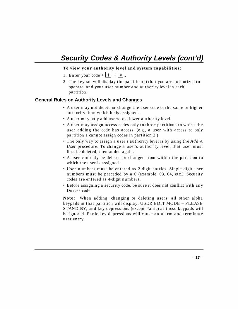
Security Codes & Authority Levels (cont’d)To view your authority level and system capabilities:
1. Enter your code + ✴ + ✴ .2. The keypad will display the partition(s) that you are authorized to
operate, and your user number and authority level in eachpartition.
General Rules on Authority Levels and Changes
• A user may not delete or change the user code of the same or higherauthority than which he is assigned.
• A user may only add users to a lower authority level.• A user may assign access codes only to those partitions to which the
user adding the code has access. (e.g., a user with access to onlypartition 1 cannot assign codes in partition 2.)
• The only way to assign a user's authority level is by using the Add AUser procedure. To change a user's authority level, that user mustfirst be deleted, then added again.
• A user can only be deleted or changed from within the partition towhich the user is assigned.
• User numbers must be entered as 2-digit entries. Single digit usernumbers must be preceded by a 0 (example, 03, 04, etc.). Securitycodes are entered as 4-digit numbers.
• Before assigning a security code, be sure it does not conflict with anyDuress code.
Note: When adding, changing or deleting users, all other alphakeypads in that partition will display, USER EDIT MODE – PLEASESTAND BY, and key depressions (except Panic) at those keypads willbe ignored. Panic key depressions will cause an alarm and terminateuser entry.
– 18 –
Security Codes & Authority Levels (cont’d)
To Exit User Edit Mode
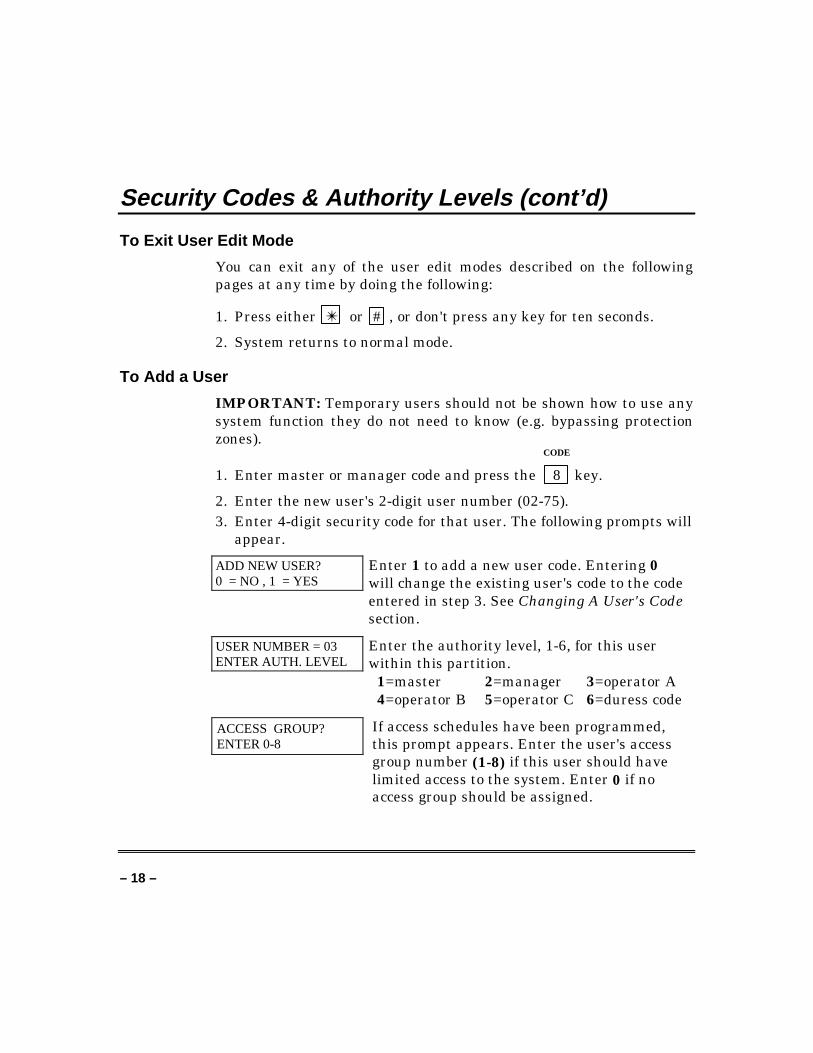
You can exit any of the user edit modes described on the followingpages at any time by doing the following:
1. Press either ✴ or # , or don't press any key for ten seconds.
2. System returns to normal mode.
To Add a User
IMPORTANT: Temporary users should not be shown how to use anysystem function they do not need to know (e.g. bypassing protectionzones).
CODE
1. Enter master or manager code and press the 8 key.
2. Enter the new user's 2-digit user number (02-75).3. Enter 4-digit security code for that user. The following prompts will
appear.
ADD NEW USER?0 = NO , 1 = YES
Enter 1 to add a new user code. Entering 0will change the existing user's code to the codeentered in step 3. See Changing A User's Codesection.
USER NUMBER = 03ENTER AUTH. LEVEL
Enter the authority level, 1-6, for this userwithin this partition.
1=master 2=manager 3=operator A4=operator B 5=operator C 6=duress code
ACCESS GROUP?ENTER 0-8
If access schedules have been programmed,this prompt appears. Enter the user's accessgroup number (1-8) if this user should havelimited access to the system. Enter 0 if noaccess group should be assigned.
– 19 –
Security Codes & Authority Levels (cont’d)
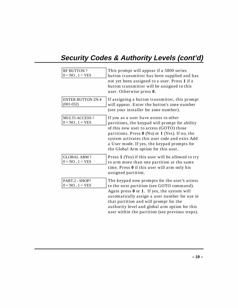
RF BUTTON ?0 = NO , 1 = YES
This prompt will appear if a 5800 seriesbutton transmitter has been supplied and hasnot yet been assigned to a user. Press 1 if abutton transmitter will be assigned to thisuser. Otherwise press 0.
ENTER BUTTON ZN #(001-032)
If assigning a button transmitter, this promptwill appear. Enter the button's zone number(see your installer for zone number).
MULTI-ACCESS ?0 = NO , 1 = YES
If you as a user have access to otherpartitions, the keypad will prompt for abilityof this new user to access (GOTO) thosepartitions. Press 0 (No) or 1 (Yes). If no, thesystem activates this user code and exits Adda User mode. If yes, the keypad prompts forthe Global Arm option for this user.
GLOBAL ARM ?0 = NO , 1 = YES
Press 1 (Yes) if this user will be allowed to tryto arm more than one partition at the sametime. Press 0 if this user will arm only hisassigned partition.
PART.2 - SHOP?0 = NO , 1 = YES
The keypad now prompts for the user’s accessto the next partition (see GOTO command).Again press 0 or 1. If yes, the system willautomatically assign a user number for use inthat partition and will prompt for theauthority level and global arm option for thisuser within the partition (see previous steps).
– 20 –
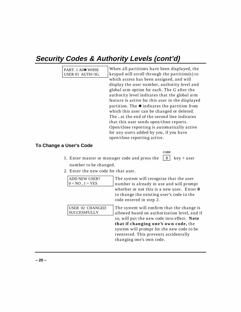
Security Codes & Authority Levels (cont’d)PART. 1 A0✱ WHSEUSER 03 AUTH=3G.
When all partitions have been displayed, thekeypad will scroll through the partition(s) towhich access has been assigned, and willdisplay the user number, authority level andglobal arm option for each. The G after theauthority level indicates that the global armfeature is active for this user in the displayedpartition. The ✱ indicates the partition fromwhich this user can be changed or deleted.The . at the end of the second line indicatesthat this user sends open/close reports.Open/close reporting is automatically activefor any users added by you, if you haveopen/close reporting active.
To Change a User's CodeCODE
1. Enter master or manager code and press the 8 key + user
number to be changed.2. Enter the new code for that user.
ADD NEW USER?0 = NO , 1 = YES
The system will recognize that the usernumber is already in use and will promptwhether or not this is a new user. Enter 0to change the existing user's code to thecode entered in step 2.
USER 02 CHANGEDSUCCESSFULLY
The system will confirm that the change isallowed based on authorization level, and ifso, will put the new code into effect. Notethat if changing one’s own code, thesystem will prompt for the new code to bereentered. This prevents accidentallychanging one's own code.
– 21 –
Security Codes & Authority Levels (cont’d)
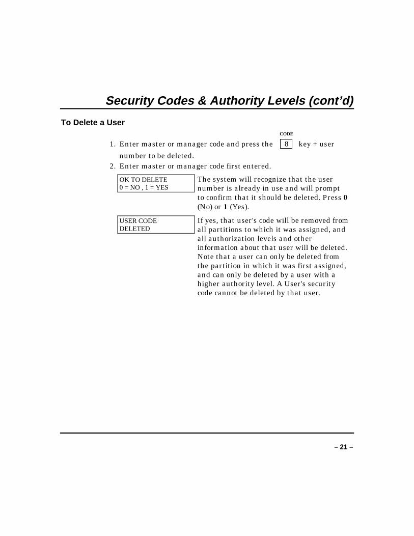
To Delete a UserCODE
1. Enter master or manager code and press the 8 key + user
number to be deleted.2. Enter master or manager code first entered.
OK TO DELETE0 = NO , 1 = YES
The system will recognize that the usernumber is already in use and will promptto confirm that it should be deleted. Press 0(No) or 1 (Yes).
USER CODEDELETED
If yes, that user's code will be removed fromall partitions to which it was assigned, andall authorization levels and otherinformation about that user will be deleted.Note that a user can only be deleted fromthe partition in which it was first assigned,and can only be deleted by a user with ahigher authority level. A User's securitycode cannot be deleted by that user.
– 22 –
Accessing Other PartitionsTo Access Another Partition
Each keypad is assigned a default partition for display purposes, andwill show only that partition's information. But, if the user isauthorized, using the GOTO command can use a keypad in onepartition to perform system functions in other partitions. Note thatonly those partitions authorized and programmed by the installer canbe accessed in this manner.
To GOTO another partition:READY
1. Enter your security code, then press ✴ + partition number (0-3).
Entering partition number 0 will return the keypad to its originalpartition.
2. LOG-ON TO AAAAPART. X COMPLETE
The keypad will remain in the newpartition until directed to go to anotherpartition, or until 2 minutes has elapsedwith no keypad activity.AAAA = alpha descriptor programmed bythe installerX = partition number
Global Arming
The Global Arming option may have been programmed for use bysome users. If Global Arming was enabled for use with your securitycode, a keypad prompt (message) will appear after pressing one of thearming function keys (Stay, Instant, Away, Maximum, Off). Follow thekeypad prompts to continue arming the system. See your installer fordetailed instructions on the use of this feature.
If global arming does not apply to your security code, use theprocedures described in the following pages.
– 23 –
Accessing Other Partitions (cont’d)
Master Keypad Operation
A master keypad is one that reflects the status of the entire system(Partitions 1-2) on its display. This is useful because it eliminates theneed for a security officer in a building to have to log-on to variouspartitions from one partition's keypad to find out where an alarm hasoccurred.
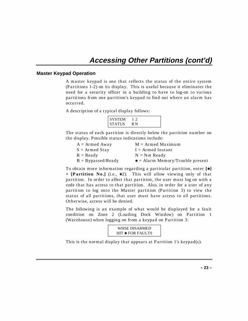
A description of a typical display follows:
SYSTEM 1 2STATUS R N
The status of each partition is directly below the partition number onthe display. Possible status indications include:
A = Armed Away M = Armed MaximumS = Armed Stay I = Armed InstantR = Ready N = Not ReadyB = Bypassed/Ready ✱ = Alarm Memory/Trouble present
To obtain more information regarding a particular partition, enter [✱ ]+ [Partition No.] (i.e., ✱ 2). This will allow viewing only of thatpartition. In order to affect that partition, the user must log on with acode that has access to that partition. Also, in order for a user of anypartition to log onto the Master partition (Partition 3) to view thestatus of all partitions, that user must have access to all partitions.Otherwise, access will be denied.
The following is an example of what would be displayed for a faultcondition on Zone 2 (Loading Dock Window) on Partition 1(Warehouse) when logging on from a keypad on Partition 3:
WHSE DISARMEDHIT ✱ FOR FAULTS
This is the normal display that appears at Partition 1's keypad(s).
– 24 –
Accessing Other Partitions (cont’d)Pressing ✱ will display:
FAULT 002 LOADINGDOCK WINDOW
Additional zone faults will be displayed one at a time. To display anew partition's status, press [✱ ] + [Partition No.]. This will displaythe status of the new partition.
The Armed LED on a master keypad will be lit only if all partitionshave been armed successfully. The Ready LED will be lit only if allpartitions are ready to arm.
The sounder on a master keypad will reflect the sound of the mostcritical condition on all of the partitions. The priority of the sounds isas follows:
A. Pulsing fire alarm soundsB. Steady burglar alarm soundsC. Trouble sounds
The sounder may be silenced by pressing any key on the masterkeypad.
– 25 –
Accessing Other Partitions (cont’d)
Common Lobby Operation
When an installation consists of a partition that is shared by users ofother partitions in a building, that shared partition may be assignedas a common lobby partition for the system. An example of this mightbe in a medical building, where there are two doctors and a commonentrance area.
This option employs logic for automatic arming and disarming of thecommon lobby. Partitions may be set to affect and/or attempt to armthe common lobby. This will affect the way the lobby will react whenarming or disarming activity occurs in another partition.
Partitions that affect the lobby will cause the following to occur:
a. When the first partition that affects the lobby is disarmed, thelobby will also be disarmed.
b. The common lobby cannot be armed unless every partition selectedto affect the lobby is armed.
c. Arming the last partition that affects the lobby will notautomatically attempt to arm the lobby.
Partitions set to arm the lobby will cause the following to occur:
a. When the first partition that affects the lobby is disarmed, thelobby will also be disarmed.
b. The common lobby cannot be armed unless every partition selectedto affect the lobby is armed.
– 26 –
Accessing Other Partitions (cont’d)
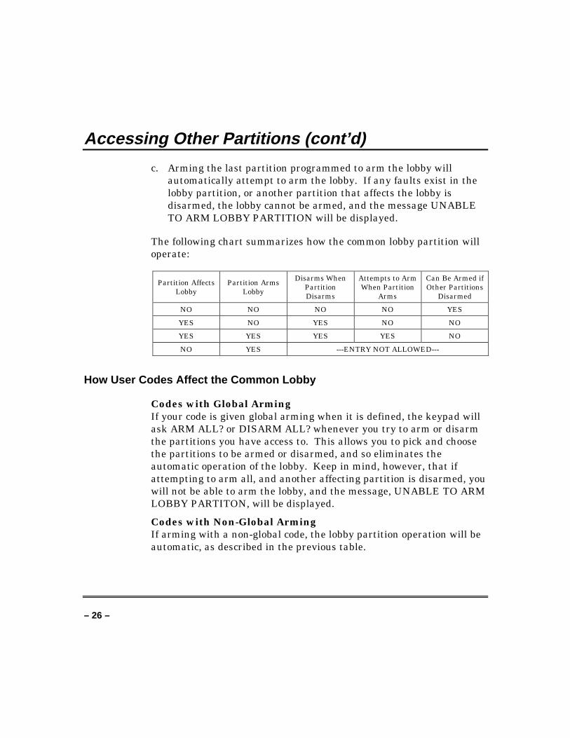
c. Arming the last partition programmed to arm the lobby willautomatically attempt to arm the lobby. If any faults exist in thelobby partition, or another partition that affects the lobby isdisarmed, the lobby cannot be armed, and the message UNABLETO ARM LOBBY PARTITION will be displayed.
The following chart summarizes how the common lobby partition willoperate:
Partition AffectsLobby
Partition ArmsLobby
Disarms WhenPartitionDisarms
Attempts to ArmWhen Partition
Arms
Can Be Armed ifOther Partitions
Disarmed
NO NO NO NO YES
YES NO YES NO NO
YES YES YES YES NO
NO YES ---ENTRY NOT ALLOWED---
How User Codes Affect the Common Lobby
Codes with Global ArmingIf your code is given global arming when it is defined, the keypad willask ARM ALL? or DISARM ALL? whenever you try to arm or disarmthe partitions you have access to. This allows you to pick and choosethe partitions to be armed or disarmed, and so eliminates theautomatic operation of the lobby. Keep in mind, however, that ifattempting to arm all, and another affecting partition is disarmed, youwill not be able to arm the lobby, and the message, UNABLE TO ARMLOBBY PARTITON, will be displayed.
Codes with Non-Global ArmingIf arming with a non-global code, the lobby partition operation will beautomatic, as described in the previous table.
– 27 –
Accessing Other Partitions (cont’d)
Other Methods of Arming/DisarmingWhen arming or disarming a partition that affects and/or arms thecommon lobby in one of the following manners, lobby logic remainsactive:• Quick-Arm• Keyswitch• Wireless Button• Wireless Keypad
– 28 –
Checking For Open Zones
Using the ✴ Ready Key
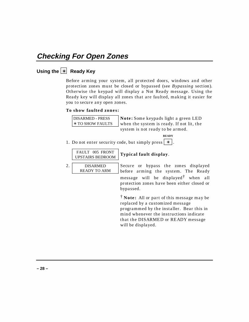
Before arming your system, all protected doors, windows and otherprotection zones must be closed or bypassed (see Bypassing section).Otherwise the keypad will display a Not Ready message. Using theReady key will display all zones that are faulted, making it easier foryou to secure any open zones.
To show faulted zones:
DISARMED - PRESS✴ TO SHOW FAULTS
Note: Some keypads light a green LEDwhen the system is ready. If not lit, thesystem is not ready to be armed.
READY
1. Do not enter security code, but simply press ✴ .
FAULT 005 FRONTUPSTAIRS BEDROOM
Typical fault display.
2. DISARMEDREADY TO ARM
Secure or bypass the zones displayedbefore arming the system. The Readymessage will be displayed† when allprotection zones have been either closed orbypassed.
† Note: All or part of this message may bereplaced by a customized messageprogrammed by the installer. Bear this inmind whenever the instructions indicatethat the DISARMED or READY messagewill be displayed.
– 29 –
Displaying All Zone Descriptors
Using the ✴ Ready Key
The alpha keypads can also display all the zone descriptors that areprogrammed in your system. The abbreviated instructions for theReady key will appear first, followed by the zone descriptors.Displaying all descriptors is useful when you need to know the zonenumber of a particular zone, as when bypassing zones.
The DISARMED-READY TO ARM message must be displayedbefore zone descriptors can be displayed.
READY
Press the ✴ key and hold down for at least five seconds.
– 30 –
Bypassing Protection Zones
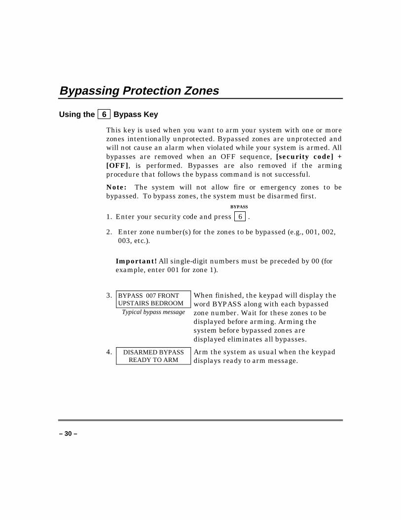
Using the 6 Bypass Key
This key is used when you want to arm your system with one or morezones intentionally unprotected. Bypassed zones are unprotected andwill not cause an alarm when violated while your system is armed. Allbypasses are removed when an OFF sequence, [security code] +[OFF], is performed. Bypasses are also removed if the armingprocedure that follows the bypass command is not successful.
Note: The system will not allow fire or emergency zones to bebypassed. To bypass zones, the system must be disarmed first.
BYPASS
1. Enter your security code and press 6 .
2. Enter zone number(s) for the zones to be bypassed (e.g., 001, 002,003, etc.).
Important! All single-digit numbers must be preceded by 00 (forexample, enter 001 for zone 1).
3. BYPASS 007 FRONTUPSTAIRS BEDROOM
Typical bypass message
When finished, the keypad will display theword BYPASS along with each bypassedzone number. Wait for these zones to bedisplayed before arming. Arming thesystem before bypassed zones aredisplayed eliminates all bypasses.
4. DISARMED BYPASSREADY TO ARM
Arm the system as usual when the keypaddisplays ready to arm message.
– 31 –
Bypassing Protection Zones (cont’d)
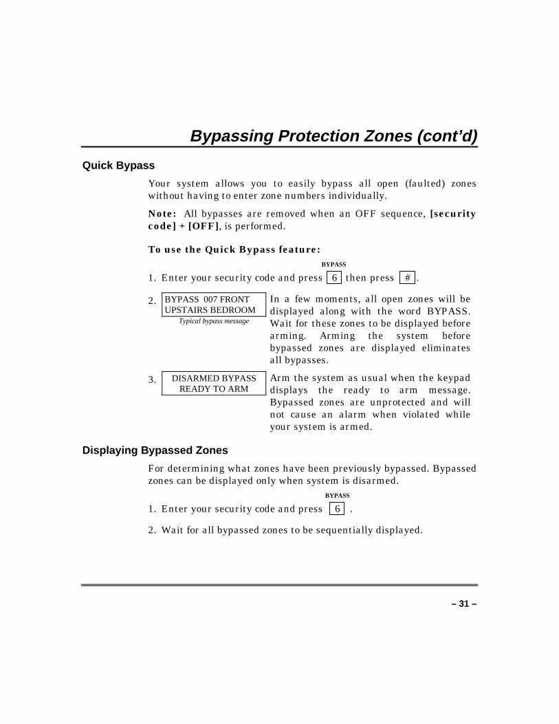
Quick Bypass
Your system allows you to easily bypass all open (faulted) zoneswithout having to enter zone numbers individually.
Note: All bypasses are removed when an OFF sequence, [securitycode] + [OFF], is performed.
To use the Quick Bypass feature: BYPASS
1. Enter your security code and press 6 then press # .
2. BYPASS 007 FRONTUPSTAIRS BEDROOM
Typical bypass message
In a few moments, all open zones will bedisplayed along with the word BYPASS.Wait for these zones to be displayed beforearming. Arming the system beforebypassed zones are displayed eliminatesall bypasses.
3. DISARMED BYPASSREADY TO ARM
Arm the system as usual when the keypaddisplays the ready to arm message.Bypassed zones are unprotected and willnot cause an alarm when violated whileyour system is armed.
Displaying Bypassed Zones
For determining what zones have been previously bypassed. Bypassedzones can be displayed only when system is disarmed.
BYPASS
1. Enter your security code and press 6 .
2. Wait for all bypassed zones to be sequentially displayed.
– 32 –
Arming Perimeter Only(With Entry Delay ON)
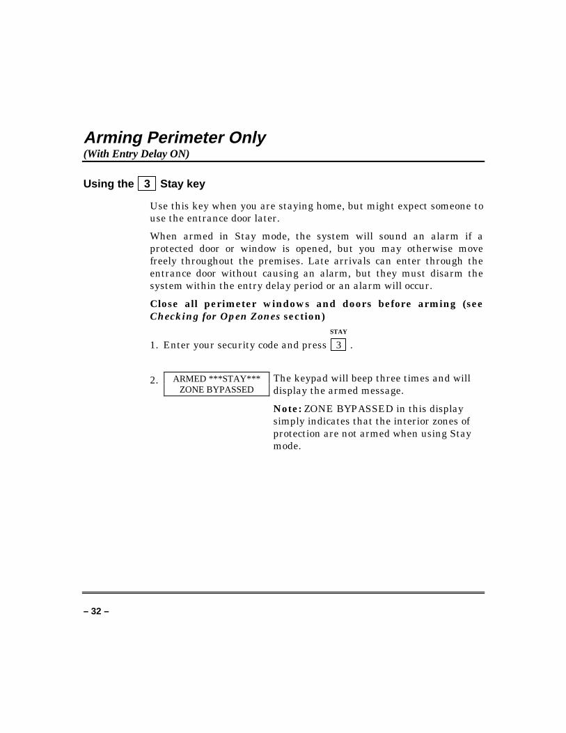
Using the 3 Stay key
Use this key when you are staying home, but might expect someone touse the entrance door later.
When armed in Stay mode, the system will sound an alarm if aprotected door or window is opened, but you may otherwise movefreely throughout the premises. Late arrivals can enter through theentrance door without causing an alarm, but they must disarm thesystem within the entry delay period or an alarm will occur.
Close all perimeter windows and doors before arming (seeChecking for Open Zones section)
STAY
1. Enter your security code and press 3 .
2. ARMED ***STAY***ZONE BYPASSED
The keypad will beep three times and willdisplay the armed message.
Note: ZONE BYPASSED in this displaysimply indicates that the interior zones ofprotection are not armed when using Staymode.
– 33 –
Arming Perimeter Only(With Entry Delay OFF)
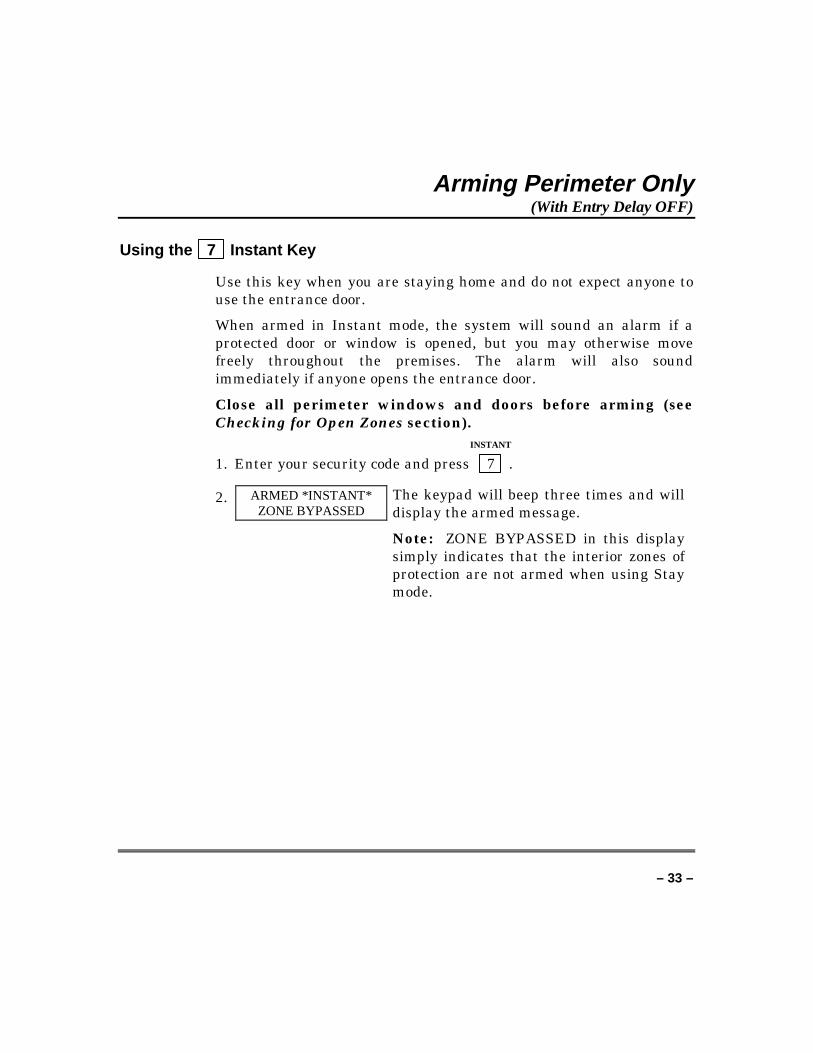
Using the 7 Instant Key
Use this key when you are staying home and do not expect anyone touse the entrance door.
When armed in Instant mode, the system will sound an alarm if aprotected door or window is opened, but you may otherwise movefreely throughout the premises. The alarm will also soundimmediately if anyone opens the entrance door.
Close all perimeter windows and doors before arming (seeChecking for Open Zones section).
INSTANT
1. Enter your security code and press 7 .
2. ARMED *INSTANT*ZONE BYPASSED
The keypad will beep three times and willdisplay the armed message.
Note: ZONE BYPASSED in this displaysimply indicates that the interior zones ofprotection are not armed when using Staymode.
– 34 –
Arming All Protection(With Entry Delay ON)
Using the 2 Away Key
Use this key when no one will be staying on the premises.
When armed in Away mode, the system will sound an alarm if aprotected door or window is opened, or if any movement is detectedinside the premises. You may leave through the entrance door duringthe exit delay period without causing an alarm. You may also reenterthrough the entrance door, but must disarm the system within theentry delay period or an alarm will occur.
Close all perimeter windows and doors before arming (seeChecking for Open Zones section)
AWAY
1. Enter your security code and press 2 .
2. ARMED **AWAY**YOU MAY EXIT NOW
The keypad will beep twice and willdisplay the armed message.
Note: The YOU MAY EXIT NOW portionof the message disappears when exit delayexpires.
– 35 –
Arming All Protection(With Entry Delay OFF)
Using the 4 Maximum Key
Use this key when the premises will be vacant for extended periods oftime such as vacations, or when no one will be moving throughprotected interior areas.
When armed in Maximum mode, the system will sound an alarm if aprotected door or window is opened, or if any movement is detectedinside the premises. You may leave through the entrance door duringthe exit delay period without causing an alarm, but an alarm will besounded as soon as someone reenters.
Close all perimeter windows and doors before arming (seeChecking for Open Zones section).
MAXIMUM
1. Enter your security code and press 4 .
2. ARMED *MAXIMUM*YOU MAY EXIT NOW
The keypad will beep twice and willdisplay the armed message.
Note: The YOU MAY EXIT NOW portionof the message disappears when exit delayexpires.
– 36 –
Disarming And Silencing Alarms
Using the 1 OFF Key
The OFF key is used to disarm the system and to silence alarm andtrouble sounds. See Summary Of Audible Notification section forinformation which will help you to distinguish between fire andburglary alarm sounds.
IMPORTANT: If you return and the main burglary sounder is on, DO NOTenter the premises, but call the police from a nearby safe location. If you returnafter an alarm has occurred and the main sounder has shut itself off, the keypadwill beep rapidly upon entering, indicating that an alarm has occurred duringyour absence. LEAVE IMMEDIATELY and CONTACT THE POLICE from anearby safe location.
To disarm the system and silence burglary or fire alarms:OFF
1. Enter your security code and press 1 .
DISARMEDREADY TO ARM
2. The READY message will be displayed (if no alarms have occurredwhile armed) and the keypad will beep once to confirm that thesystem is disarmed.
Memory of Alarm
The keypad displays the zone number and type of alarm for any zonethat has an alarm condition. These messages will remain displayeduntil cleared by a user. If an alarm has occurred, note the zonenumber displayed on the keypad and repeat step 1 above to clear theMemory of Alarm and restore the READY message display. If theREADY message will not display, go to the displayed zone and remedythe fault (e.g., close windows). If the fault cannot be remedied, notifythe alarm agency.
If the system was armed when the alarm occurred, repeat step 1twice: once to disarm the system, a second time to clear the display.
– 37 –
Using The Keyswitch
General
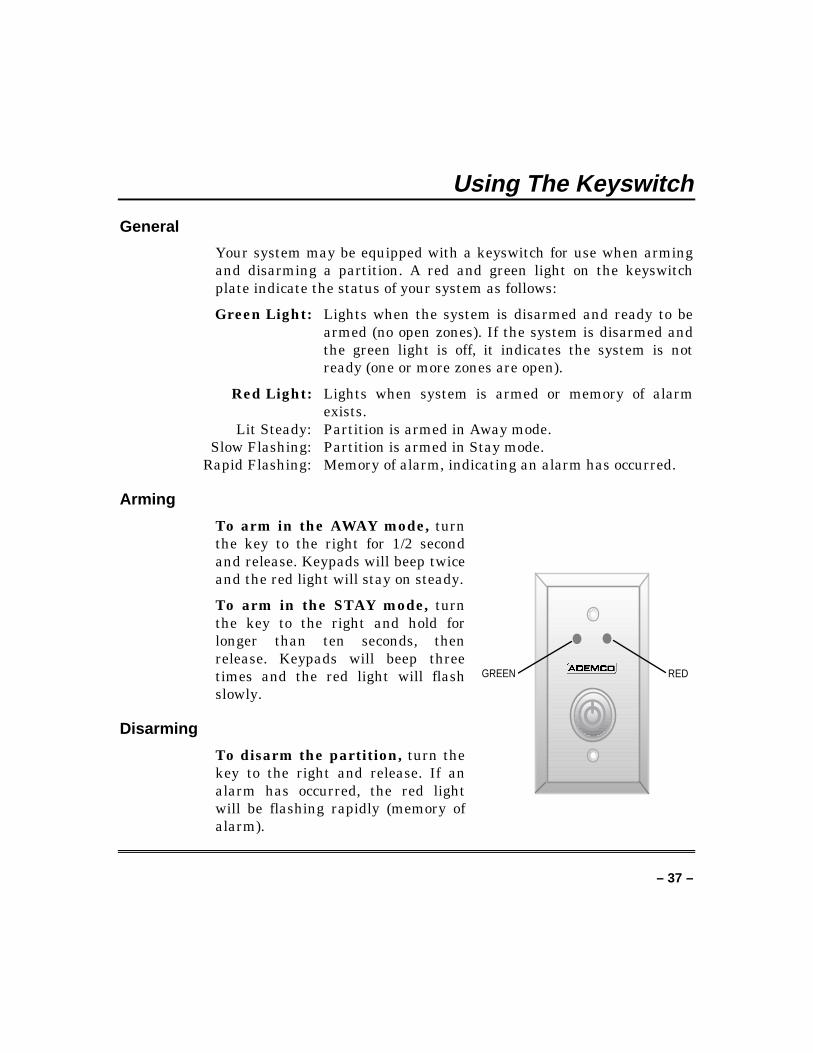
Your system may be equipped with a keyswitch for use when armingand disarming a partition. A red and green light on the keyswitchplate indicate the status of your system as follows:
Green Light: Lights when the system is disarmed and ready to bearmed (no open zones). If the system is disarmed andthe green light is off, it indicates the system is notready (one or more zones are open).
Red Light: Lights when system is armed or memory of alarmexists.
Lit Steady: Partition is armed in Away mode.Slow Flashing: Partition is armed in Stay mode.
Rapid Flashing: Memory of alarm, indicating an alarm has occurred.
Arming
To arm in the AWAY mode, turnthe key to the right for 1/2 secondand release. Keypads will beep twiceand the red light will stay on steady.
To arm in the STAY mode, turnthe key to the right and hold forlonger than ten seconds, thenrelease. Keypads will beep threetimes and the red light will flashslowly.
Disarming
To disarm the partition, turn thekey to the right and release. If analarm has occurred, the red lightwill be flashing rapidly (memory ofalarm).
GREEN RED
– 38 –
Chime Mode
Using the 9 Key
Your system can be set to alert you to the opening of a door or awindow while it is disarmed using Chime mode. When activated, threetones will sound at the keypad whenever a protected perimeter door orwindow is opened, and the Not Ready message will be displayed.Pressing the Ready key will display the open protection points.
Note that Chime mode can be activated only when the system isdisarmed.
1. To turn Chime mode on, enter the security code and press 9 .
CHIME MODE ON The CHIME MODE ON message willappear for about two seconds thendisappear. To display this message again(to determine whether chime mode is on oroff), simply press and hold down theChime key for five seconds.
2. To turn Chime mode off, enter the security code and press 9
again.
CHIME MODE OFF The CHIME MODE OFF message willappear for about two seconds thendisappear. To display this message again(to determine whether chime mode is on oroff), simply press and hold down theChime key for five seconds.
– 39 –
Viewing Central Station Messages
General Information
Users of the system may periodically receive messages on theirdisplay screens from their monitoring agency or installer. When amessage is waiting to be viewed, the message shown below willappear.
MESSAGE. PRESS 0FOR 5 SECS.
1. Press and hold down 0 key for five seconds.
2. The message could take up to four screens to display all theinformation available.
– 40 –
Panic Keys(For Manually Activating Silent And/Or Audible Alarms)
Using Panic Keys
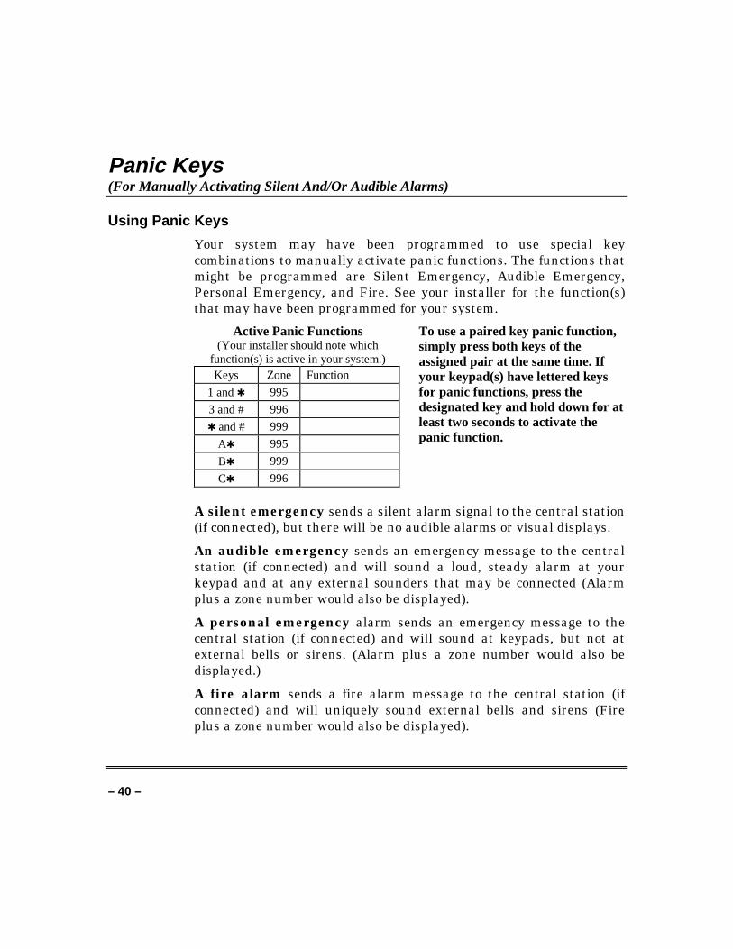
Your system may have been programmed to use special keycombinations to manually activate panic functions. The functions thatmight be programmed are Silent Emergency, Audible Emergency,Personal Emergency, and Fire. See your installer for the function(s)that may have been programmed for your system.
Active Panic Functions(Your installer should note which
function(s) is active in your system.)Keys Zone Function
1 and ✱ 995
3 and # 996
✱ and # 999
A✱ 995
B✱ 999
C✱ 996
To use a paired key panic function,simply press both keys of theassigned pair at the same time. Ifyour keypad(s) have lettered keysfor panic functions, press thedesignated key and hold down for atleast two seconds to activate thepanic function.
A silent emergency sends a silent alarm signal to the central station(if connected), but there will be no audible alarms or visual displays.
An audible emergency sends an emergency message to the centralstation (if connected) and will sound a loud, steady alarm at yourkeypad and at any external sounders that may be connected (Alarmplus a zone number would also be displayed).
A personal emergency alarm sends an emergency message to thecentral station (if connected) and will sound at keypads, but not atexternal bells or sirens. (Alarm plus a zone number would also bedisplayed.)
A fire alarm sends a fire alarm message to the central station (ifconnected) and will uniquely sound external bells and sirens (Fireplus a zone number would also be displayed).
– 41 –
Speed Key (Macros)
General Information
The A, B, C, and/or D keys can be used to activate a string ofcommands up to 32 keystrokes each. These commands are known as amacro and are stored in the system’s memory. Typical Speed Keyfunctions include:
• Arming sequences. These sequences must first bypass certainzones before arming.
• Seldom used but repeatable sequences.• Relay activation sequences.
Defining
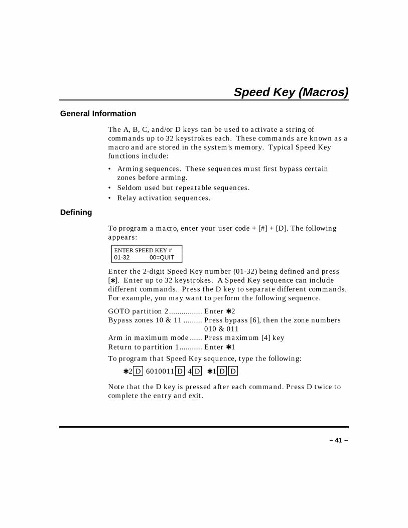
To program a macro, enter your user code + [#] + [D]. The followingappears:
ENTER SPEED KEY #01-32 00=QUIT
Enter the 2-digit Speed Key number (01-32) being defined and press[✱ ]. Enter up to 32 keystrokes. A Speed Key sequence can includedifferent commands. Press the D key to separate different commands.For example, you may want to perform the following sequence.
GOTO partition 2................ Enter ✱ 2Bypass zones 10 & 11 ......... Press bypass [6], then the zone numbers
010 & 011Arm in maximum mode ...... Press maximum [4] keyReturn to partition 1........... Enter ✱ 1
To program that Speed Key sequence, type the following:
✱ 2 D 6010011 D 4 D ✱ 1 D D
Note that the D key is pressed after each command. Press D twice tocomplete the entry and exit.
– 42 –
Speed Key (Macros) (cont’d)Note: When defining Speed Key sequences, do not use the [#] key torepresent Quick Arming. The system uses the code entered inresponse to the prompt to initiate commands in a Speed Key sequence,so the quick arm key is unnecessary. The system interprets the use ofthe [#] key in a Speed Key sequence as its designated function only.
Executing
To execute a Speed Key sequence, do the following:
If a lettered key, A-B-C, has been assigned as a Speed Key, press andhold down the appropriate key (about 2 seconds). If a user code isrequired for any part of the Speed Key sequence, the following promptappears. Otherwise, the Speed Key sequence automatically begins.
ENTER USER CODE ✴✴✴✴
Enter your user code. The defined Speed Key sequence will beginautomatically.To activate a Speed Key not assigned to the A-B-C keys, press andhold down the [D] key for 2 seconds until the following promptappears:
ENTER SPEED KEY #01-32 00=QUIT
Enter the desired Speed Key number.
If a user code is required for any part of the Speed Key sequence, thefollowing prompt appears. Otherwise, the Speed Key sequenceautomatically begins.
ENTER USER CODE ✴✴✴✴
Enter your user code. The programmed Speed Key sequence willbegin automatically.
– 43 –
Access Door Control
General Information
Your system may be set up such that a locked access door (such as in alobby) can be unlocked for two seconds by entering your security code+ [0] on your keypad. Ask your installer if this has been done in oursystem.
– 44 –
Using #70 Relay Menu Mode
General Information
Your system may be set up so that certain lights or other devices canbe turned on or off by using the #70 command from either a keypad ora telephone keypad (if 4285 or 4286 VIP module is used). Ask yourinstaller if this has been done in your system.
To activate relays from a keypad, enter [4-digit security code] + [#]+ [70]. Follow the keypad prompts described below.
To activate relays using a telephone and 4285 or 4286 VIPmodule, first dial the 2-digit phone access code. When the systemacknowledges the access, enter [4-digit security code] + [#] + [70]. Thefollowing prompts/voice responses will begin.
ENTER DEVICE NO.00=QUIT 01
Voice: ENTER DEVICE CODE NOW
Enter the 2-digit number of the device to beactivated.
Note that if an invalid number is entered, thesystem will simply ask you to reenter thenumber.
NN DEVICE IS OFFHIT 0=OFF , 1=ON
Voice: voice descriptor DEVICE nn ON/OFF.FOR voice descriptor ON ENTER 1, FOR voicedescriptor OFF ENTER 0
Press 0 or 1 to turn the device off or onrespectively.
nn represents the 2-digit device number andvoice descriptor is the relay voice descriptorprogrammed by the installer.
– 45 –
Using #70 Relay Menu Mode (cont’d)NN DEVICE IS OFFHIT THE T KEY
Voice: voice descriptor DEVICE nn ON/OFF.TO EXIT ENTER 00 NOW
From a keypad, press T to continue. TheENTER DEVICE NO. prompt will appear.
From a telephone keypad, enter 00 to exit,or enter the next relay number to beprogrammed. The current on/off state of thatrelay will be annunciated as described above.Alternatively, if six seconds elapses with nokey depression, the 4285 or 4286 VIP modulewill annunciate the ENTER DEVICE CODENOW message.
– 46 –
Using Schedules
Delaying the Closing Time
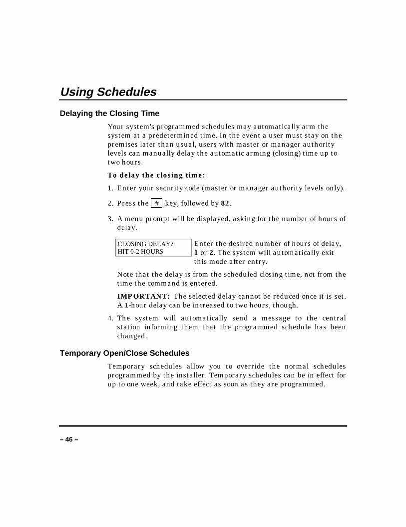
Your system's programmed schedules may automatically arm thesystem at a predetermined time. In the event a user must stay on thepremises later than usual, users with master or manager authoritylevels can manually delay the automatic arming (closing) time up totwo hours.
To delay the closing time:
1. Enter your security code (master or manager authority levels only).
2. Press the # key, followed by 82.
3. A menu prompt will be displayed, asking for the number of hours ofdelay.
CLOSING DELAY?HIT 0-2 HOURS
Enter the desired number of hours of delay,1 or 2. The system will automatically exitthis mode after entry.
Note that the delay is from the scheduled closing time, not from thetime the command is entered.
IMPORTANT: The selected delay cannot be reduced once it is set.A 1-hour delay can be increased to two hours, though.
4. The system will automatically send a message to the centralstation informing them that the programmed schedule has beenchanged.
Temporary Open/Close Schedules
Temporary schedules allow you to override the normal schedulesprogrammed by the installer. Temporary schedules can be in effect forup to one week, and take effect as soon as they are programmed.
– 47 –
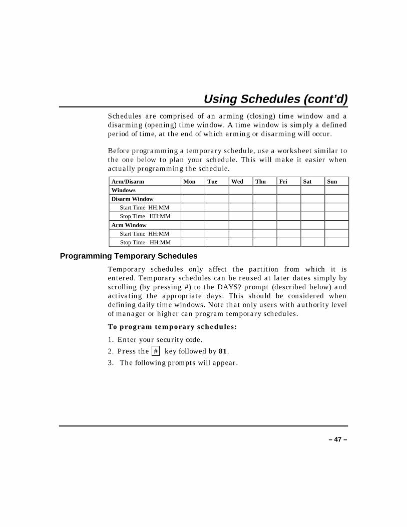
Using Schedules (cont’d)Schedules are comprised of an arming (closing) time window and adisarming (opening) time window. A time window is simply a definedperiod of time, at the end of which arming or disarming will occur.
Before programming a temporary schedule, use a worksheet similar tothe one below to plan your schedule. This will make it easier whenactually programming the schedule.
Arm/Disarm Mon Tue Wed Thu Fri Sat Sun
Windows
Disarm WindowStart Time HH:MM
Stop Time HH:MM
Arm WindowStart Time HH:MM
Stop Time HH:MM
Programming Temporary Schedules
Temporary schedules only affect the partition from which it isentered. Temporary schedules can be reused at later dates simply byscrolling (by pressing #) to the DAYS? prompt (described below) andactivating the appropriate days. This should be considered whendefining daily time windows. Note that only users with authority levelof manager or higher can program temporary schedules.
To program temporary schedules:
1. Enter your security code.
2. Press the # key followed by 81.
3. The following prompts will appear.
– 48 –
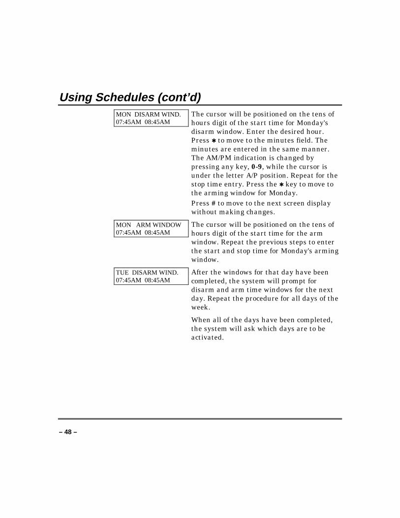
Using Schedules (cont’d)MON DISARM WIND.07:45AM 08:45AM
The cursor will be positioned on the tens ofhours digit of the start time for Monday'sdisarm window. Enter the desired hour.Press ✱ to move to the minutes field. Theminutes are entered in the same manner.The AM/PM indication is changed bypressing any key, 0-9, while the cursor isunder the letter A/P position. Repeat for thestop time entry. Press the ✱ key to move tothe arming window for Monday.Press # to move to the next screen displaywithout making changes.
MON ARM WINDOW07:45AM 08:45AM
The cursor will be positioned on the tens ofhours digit of the start time for the armwindow. Repeat the previous steps to enterthe start and stop time for Monday's armingwindow.
TUE DISARM WIND.07:45AM 08:45AM
After the windows for that day have beencompleted, the system will prompt fordisarm and arm time windows for the nextday. Repeat the procedure for all days of theweek.
When all of the days have been completed,the system will ask which days are to beactivated.
– 49 –
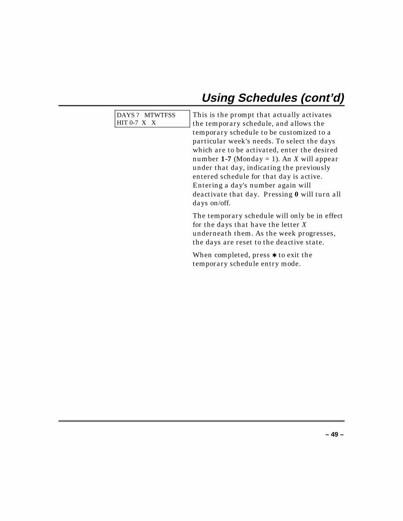
Using Schedules (cont’d)DAYS ? MTWTFSSHIT 0-7 X X
This is the prompt that actually activatesthe temporary schedule, and allows thetemporary schedule to be customized to aparticular week's needs. To select the dayswhich are to be activated, enter the desirednumber 1-7 (Monday = 1). An X will appearunder that day, indicating the previouslyentered schedule for that day is active.Entering a day's number again willdeactivate that day. Pressing 0 will turn alldays on/off.
The temporary schedule will only be in effectfor the days that have the letter Xunderneath them. As the week progresses,the days are reset to the deactive state.
When completed, press ✱ to exit thetemporary schedule entry mode.
– 50 –
Programming Device Timers
General InformationDevice timers consist of an ON time & an OFF time, and selected daysof the week in which they are active. There are up to 20 timers thatcan be used to control various devices, such as lights or appliances.Your installer will have programmed the appropriate devices into thesystem (up to 16 devices can be programmed).
Each timer controls a single device (designated as an output number)that you select. For example, timer 1 might be set to turn the porchlights on at 7:00pm and turn them off at 11:00pm. Timer 2 might turnon the air conditioner Monday-Friday at 4:30pm to cool the premisesbefore you arrive at 5:00pm, and turn it off at 10:00pm when you areretiring for the night. If desired, different timers can control the samedevice. For example, timer 2 could be used Monday-Friday as in theprevious example, and timer 3 could be set to turn the air conditioneron and off at different times Saturday and Sunday.
To enter the device timer menu mode:
Enter your security code, then press the # key followed by 83.
OUTPUT TIMER # ?01-20,00=QUIT 01
Up to 20 timers can be programmed. Eachtimer is identified by a number 1-20. Enterthe desired timer number to be programmed(1-20). Press ✱ to accept entry.
06 07:00P 11:45PPORCH LITE 04
If that timer number has already beenprogrammed, a summary screen will appear.In this example:
06 = Timer #04 = Output Device # affected by this timerPORCH LITE = Output Descriptor forDevice 407:00PM = Start Time;11:45PM = Stop Time
Press ✱ to continue.
– 51 –
Programming Device Timers (cont’d)See your installer fordevice numbers.
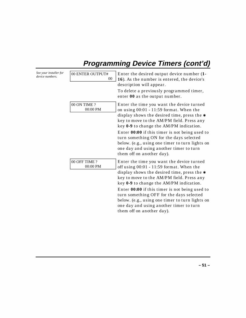
00 ENTER OUTPUT#00
Enter the desired output device number (1-16). As the number is entered, the device'sdescription will appear.To delete a previously programmed timer,enter 00 as the output number.
00 ON TIME ?00:00 PM
Enter the time you want the device turnedon using 00:01 - 11:59 format. When thedisplay shows the desired time, press the ✱key to move to the AM/PM field. Press anykey 0-9 to change the AM/PM indication.Enter 00:00 if this timer is not being used toturn something ON for the days selectedbelow. (e.g., using one timer to turn lights onone day and using another timer to turnthem off on another day).
00 OFF TIME ?00:00 PM
Enter the time you want the device turnedoff using 00:01 - 11:59 format. When thedisplay shows the desired time, press the ✱key to move to the AM/PM field. Press anykey 0-9 to change the AM/PM indication.Enter 00:00 if this timer is not being used toturn something OFF for the days selectedbelow. (e.g., using one timer to turn lights onone day and using another timer to turnthem off on another day).
– 52 –
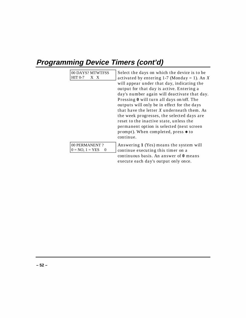
Programming Device Timers (cont’d)00 DAYS? MTWTFSSHIT 0-7 X X
Select the days on which the device is to beactivated by entering 1-7 (Monday = 1). An Xwill appear under that day, indicating theoutput for that day is active. Entering aday's number again will deactivate that day.Pressing 0 will turn all days on/off. Theoutputs will only be in effect for the daysthat have the letter X underneath them. Asthe week progresses, the selected days arereset to the inactive state, unless thepermanent option is selected (next screenprompt). When completed, press ✱ tocontinue.
00 PERMANENT ?0 = NO, 1 = YES 0
Answering 1 (Yes) means the system willcontinue executing this timer on acontinuous basis. An answer of 0 meansexecute each day's output only once.
– 53 –
Event Log ProceduresGeneral Information
The system has the ability to recordvarious events in a history log whereineach event is recorded in one of fivecategories (listed below), with the timeand date of its occurrence. The EventLog holds up to 224 events, with theoldest event being replaced by thelogging of any new event after the logis full. Using an alpha keypad, theEvent Log can be viewed one categoryat a time, or can display all events,regardless of category (All Event Log).The system also allows selection ofdisplaying the Complete log, or onlythose events occurring since the lastinstaller service (Recent). In addition,users authorized to access thosepartitions can view events in the otherpartitions. Note that events aredisplayed in chronological order, frommost recent to oldest.
To Display The Event Log
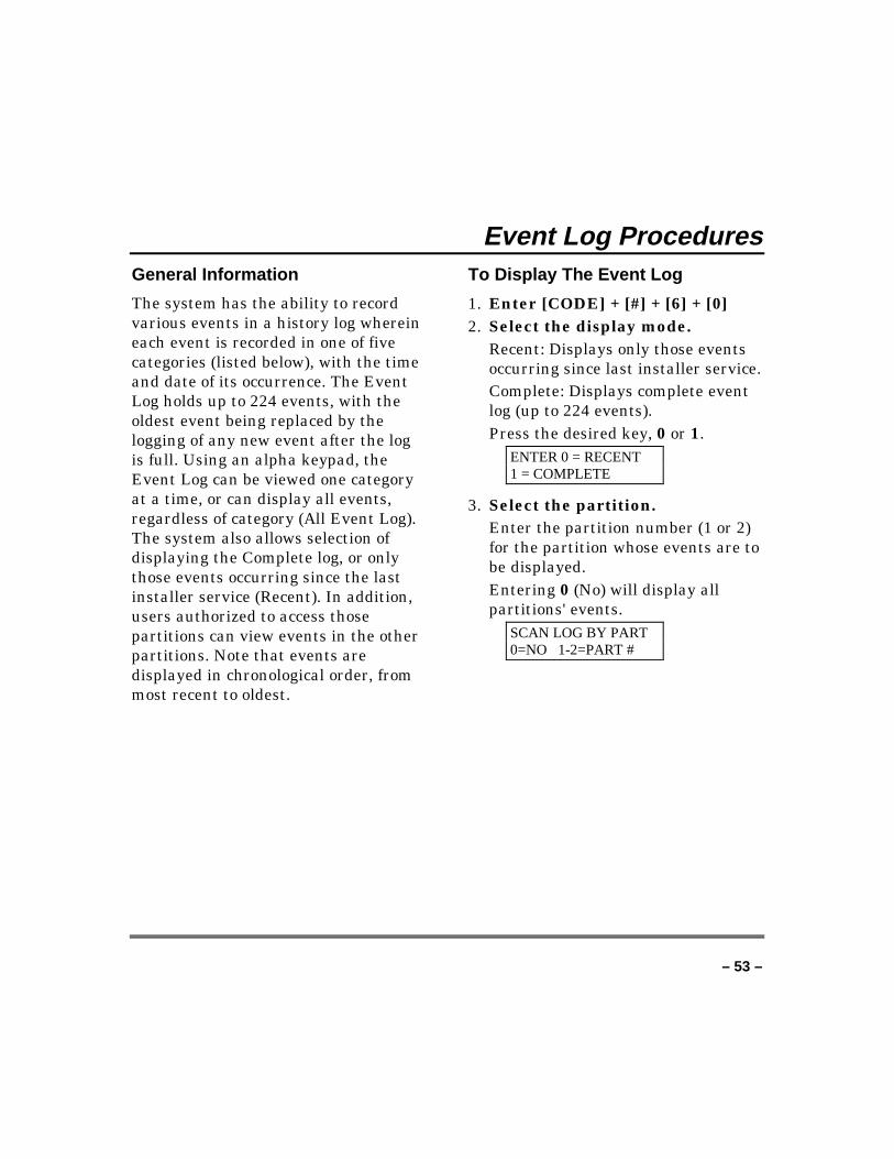
1. Enter [CODE] + [#] + [6] + [0]2. Select the display mode.
Recent: Displays only those eventsoccurring since last installer service.Complete: Displays complete eventlog (up to 224 events).Press the desired key, 0 or 1.
ENTER 0 = RECENT1 = COMPLETE
3. Select the partition.Enter the partition number (1 or 2)for the partition whose events are tobe displayed.Entering 0 (No) will display allpartitions' events.
SCAN LOG BY PART0=NO 1-2=PART #
– 54 –
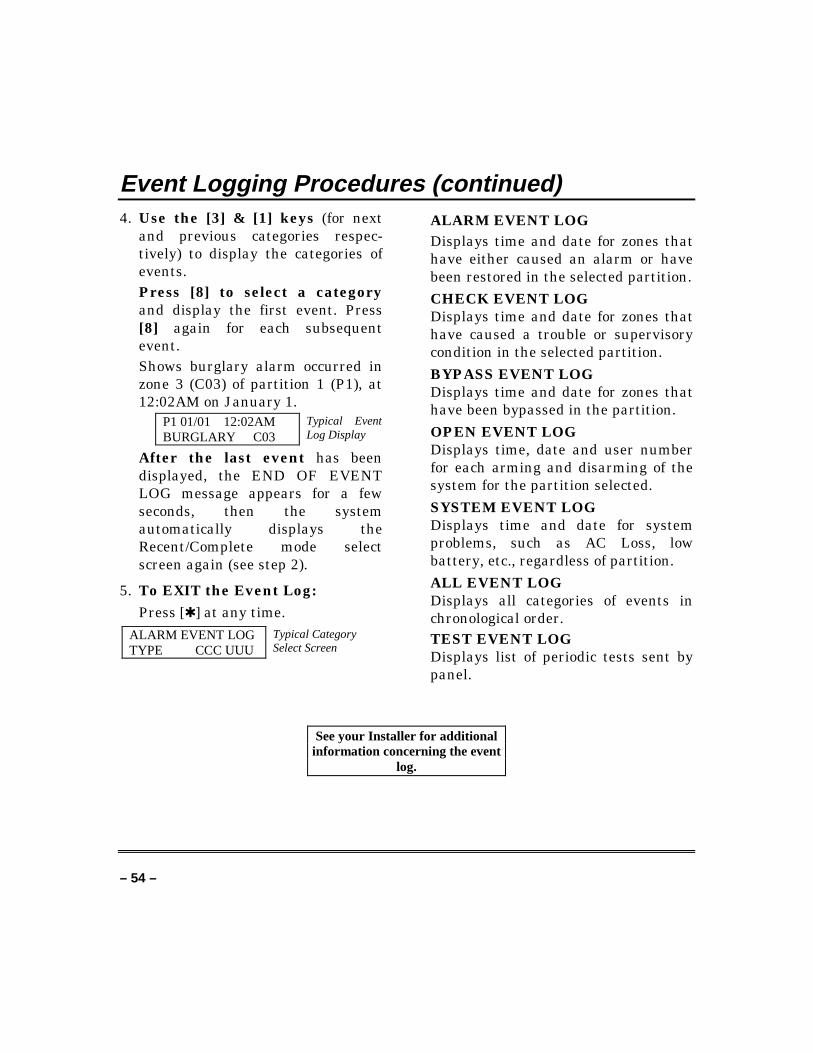
Event Logging Procedures (continued)4. Use the [3] & [1] keys (for next
and previous categories respec-tively) to display the categories ofevents.Press [8] to select a categoryand display the first event. Press[8] again for each subsequentevent.Shows burglary alarm occurred inzone 3 (C03) of partition 1 (P1), at12:02AM on January 1.
P1 01/01 12:02AMBURGLARY C03
Typical EventLog Display
After the last event has beendisplayed, the END OF EVENTLOG message appears for a fewseconds, then the systemautomatically displays theRecent/Complete mode selectscreen again (see step 2).
5. To EXIT the Event Log:Press [✱ ] at any time.
ALARM EVENT LOGTYPE CCC UUU
Typical CategorySelect Screen
ALARM EVENT LOGDisplays time and date for zones thathave either caused an alarm or havebeen restored in the selected partition.CHECK EVENT LOGDisplays time and date for zones thathave caused a trouble or supervisorycondition in the selected partition.BYPASS EVENT LOGDisplays time and date for zones thathave been bypassed in the partition.OPEN EVENT LOGDisplays time, date and user numberfor each arming and disarming of thesystem for the partition selected.SYSTEM EVENT LOGDisplays time and date for systemproblems, such as AC Loss, lowbattery, etc., regardless of partition.ALL EVENT LOGDisplays all categories of events inchronological order.TEST EVENT LOGDisplays list of periodic tests sent bypanel.
See your Installer for additionalinformation concerning the event
log.
– 55 –
Testing The System(To Be Conducted Weekly)
Using the 5 Test Key
The Test key puts your system into Test mode, which allows eachprotection point to be checked for proper operation.
1. Disarm the system and close all protected windows, doors, etc.READY should be displayed.
TEST
2. Enter your security code and press the 5 key.
3. The external sounder of any unsupervised bell output should soundfor three seconds and then turn off. If the sounder does not sound,it may be due to dialer communication activity. Wait a fewminutes and try again. If the sounder still does not sound, CALLFOR SERVICE IMMEDIATELY.
4. The keypad will sound a single beep every 15 seconds as areminder that the system is in Test mode. Each time a protectionzone is faulted (opened), the keypad should beep three times. If thesounder does not sound, CALL FOR SERVICE IMMEDIATELY.
Note that no alarm reports will be sent to the central monitoring station whilethe system is in Test mode.
– 56 –
Testing The System (cont’d)
Testing Your System
1. Open and close each protected door and window in turn and listenfor three beeps. The identification of each faulted protection pointshould appear on the display.
2. Walk in front of any interior motion detectors (if used) and listenfor three beeps as movement is detected. The identification of thedetector should appear on the display when it is activated.
3. Follow the manufacturer's instructions to test all smoke detectorsto ensure that all are functioning properly. The identification ofeach detector (or the zone number of the zone assigned to thedetector) should appear on the display when each is activated.
4. When all protection points have been checked, there should be nozone identification numbers displayed. If a problem is experiencedwith any protection point (no confirming sounds, no display), CALLFOR SERVICE IMMEDIATELY.
5. Turn off Test mode by entering the security code and pressing theOff key.
– 57 –
Fire Alarm System
General
Your fire alarm system (if installed) is on 24 hours a day, providingcontinuous protection. In the event of an emergency, the installedsmoke and heat detectors will automatically send signals to yourControl/Communicator, triggering a loud interrupting sound from thekeypad. An interrupted sound will also be produced by optionalexterior sounders. A FIRE message will appear at your keypad andremain on until you silence the alarm.
In Case Of Fire Alarm
1. Should you become aware of a fire emergency before your detectorssense the problem, go to your nearest keypad and manuallyinitiate an alarm by pressing the panic key assigned as fireemergency (if programmed by the installer) and hold down for atleast two seconds.
2. Evacuate all occupants from the premises.
3. If flames and/or smoke are present, leave the premises and notifyyour local Fire Department immediately.
4. If no flames or smoke are apparent, investigate the cause of thealarm. The zone descriptor of the zone(s) in an alarm conditionwill appear at the keypad.
Silencing A Fire Alarm
1. Silence the alarm by entering your code and pressing the Off key.To clear the display, enter your code and press the Off key again.
– 58 –
Fire Alarm System (cont’d)
2. If the keypad does not indicate a Ready condition after the secondOff sequence, press the Ready key to display the zone(s) that arefaulted. Be sure to check that smoke detectors are not respondingto smoke or heat producing objects in their vicinity. Should this bethe case, eliminate the source of heat or smoke.
3. If this does not remedy the problem, there may still be smoke inthe detector. Clear it by fanning the detector for about 30 seconds.
4. When the problem has been corrected, clear the display byentering your code and pressing the Off key.
Fire Display Lock
If several zones produce an alarm before any are silenced, the systemcan be programmed to lock the keypad display with the first zone thatproduced an alarm. Ask your installer if your system has beenactivated with this feature.
To display the other zone(s), press the [✱ ] key for each zone. Also theA, B, or C keys can be programmed to scroll the keypad display toview the previous or subsequent fire alarms.
Fire Drill Test (Code + # + 69)
The Fire Drill test causes supervised fire bells to be activated (ineither steady or pulsing manner as programmed in the system), forthe purpose of conducting a fire drill or a bell test. This test can onlybe activated from Partition 1 keypads by the installer, or a masteruser, as follows:
1. Enter the corresponding security code and press [#} + 69 (makesure the burglary portion of the system is disarmed). Keypads willdisplay FIRE DRILL ACTIVE while the test is active.
– 59 –
Fire Alarm System (cont’d)
2. The test may be stopped by entering any security code andpressing [OFF].
Note: The system continues to monitor all 24-hour zones (Fire, Panic,etc.), while this test is active, and will end the test when an alarmcondition is detected. This test should be conducted at periodicintervals as determined by the local authority having jurisdiction.
– 60 –
Trouble Conditions
Typical Trouble Displays
The word CHECK or TRBL on the keypad's display, accompanied by arapid beeping at the keypad, indicates that there is a trouble conditionin the system.
To silence the beeping sound for trouble conditions, press any key.
• A display of CHECK or TRBL accompanied by a display of CALLSERVICE indicates that a problem exists with the system thateliminates some of the protection. CALL FOR SERVICEIMMEDIATELY.
• A display of CHECK or TRBL accompanied by a display of one ormore zone descriptors indicates that a problem exists with thosezone(s). First, determine if the zone(s) displayed are intact andmake them so if they are not. If the problem has been corrected,the display of the zone descriptor(s) and CHECK or TRBL shoulddisappear. If not, key an Off sequence, [Code] + [OFF], to clearthe display. If the display persists, CALL FOR SERVICEIMMEDIATELY.
• A display of CHECK or TRBL accompanied by a numeric displayof 6XX, where XX = 01-16, indicates a trouble on a supervisedrelay (corresponding relay number 01-16).
• A display of CHECK or TRBL accompanied by a numeric displayof 8XX, where XX = 00-30, indicates a trouble on a peripheraldevice (connected to the panel’s keypad terminals) of acorresponding device address (00-30).
• A display of CHECK or TRBL accompanied by a numeric displayof 9XX, where XX = 00-99, indicates a system trouble exists(dialers, bell outputs, ground fault, etc.). These zones are asfollows:
– 61 –
Trouble Conditions (cont’d)970: Bell 1 Output 975: Dialer 2971: Bell 2 Output 988: 2nd RF Receiver – not receiving972: Earth Ground Fault signals973: J2 Trigger Output 990: 1st RF Receiver – not receiving974: Dialer 1 signals
997: Polling Loop Short
• A display of COMM. FAILURE at the keypad indicates that afailure has occurred in the telephone communication portion ofyour system. CALL FOR SERVICE IMMEDIATELY.
• A display of SYSTEM LO BAT, accompanied by a once per minutebeeping at the keypad indicates that a low system batterycondition exists. CALL FOR SERVICE IMMEDIATELY.
• A display of LO BAT and a zone descriptor, accompanied by aonce-per-minute beeping at the keypad indicates that a lowbattery condition exists in the wireless transmitter displayed.CALL FOR SERVICE IMMEDIATELY.
• A display of MODEM COMM indicates that the control is on-linewith the central station's remote computer. The control will notoperate while on-line.
• A display of HSENS and a zone number indicates a smoke detectorwith a high sensitivity level, which may cause false alarms. CALLFOR SERVICE IMMEDIATELY.
• A display of LSENS and a zone number indicates a smoke detectorwith a low sensitivity level. Detectors with a low sensitivity mightnot detect a smoke condition. CALL FOR SERVICEIMMEDIATELY.
– 62 –
Trouble Conditions (cont’d)
Power Failure
If the Power indicator is off, operating power for the system hasstopped and is inoperative. CALL FOR SERVICE IMMEDIATELY. Ifthe Power indicator is on, but the message AC LOSS is displayed, thekeypad is operating on battery power only. If only some lights are outon the premises, check circuit breakers and fuses and reset or replaceas necessary. CALL FOR SERVICE IMMEDIATELY if AC powercannot be restored.
SERVICING INFORMATION
Your local Ademco dealer is the person best qualified to service youralarm system. Arranging some kind of regular service program withhim is advisable.
Your local Ademco dealer is:
Name:
Address:
Phone:
– 63 –
Recommendations For Proper Protection
THE FOLLOWING RECOMMENDATIONS FOR THE LOCATION OF FIREAND BURGLARY DETECTION DEVICES HELP PROVIDE PROPERCOVERAGE FOR THE PROTECTED PREMISES.
Recommendations For Smoke And Heat Detectors
With regard to the number and placement of smoke/heat detectors, wesubscribe to the recommendations contained in the National FireProtection Association's (NFPA) Standard #72 noted below.
Early warning fire detection is best achieved by the installationof fire detection equipment in all rooms and areas of thehousehold as follows: For minimum protection a smoke detectorshould be installed outside of each separate sleeping area, andon each additional floor of a multi-floor family living unit,including basements. The installation of smoke detectors inkitchens, attics (finished or unfinished), or in garages is notnormally recommended.
For additional protection the NFPA recommends that you install heator smoke detectors in the living room, dining room, bedroom(s),kitchen, hallway(s), attic, furnace room, utility and storage rooms,basements and attached garages.
– 64 –
Recommendations For Proper Protection (cont’d)
DININGKITCHEN
BEDROOM
BEDROOM
BEDROOM
BEDROOM
LIVING ROOM
✪
✪
✪ ✪
✪
▲
▲
BEDROOM
BDRM
BDRM
DINING
LIVING ROOM
TV ROOM KITCHEN
■■
■
✪
✪
✪
✪ ✪
✪
▲
✪
✪
✪
BEDROOM BEDROOMTOBR
■
■
■
■
■
LVNG RM
BASEMENT
KTCHN▲
▲
. CLOSEDDOOR
GARAGE▲
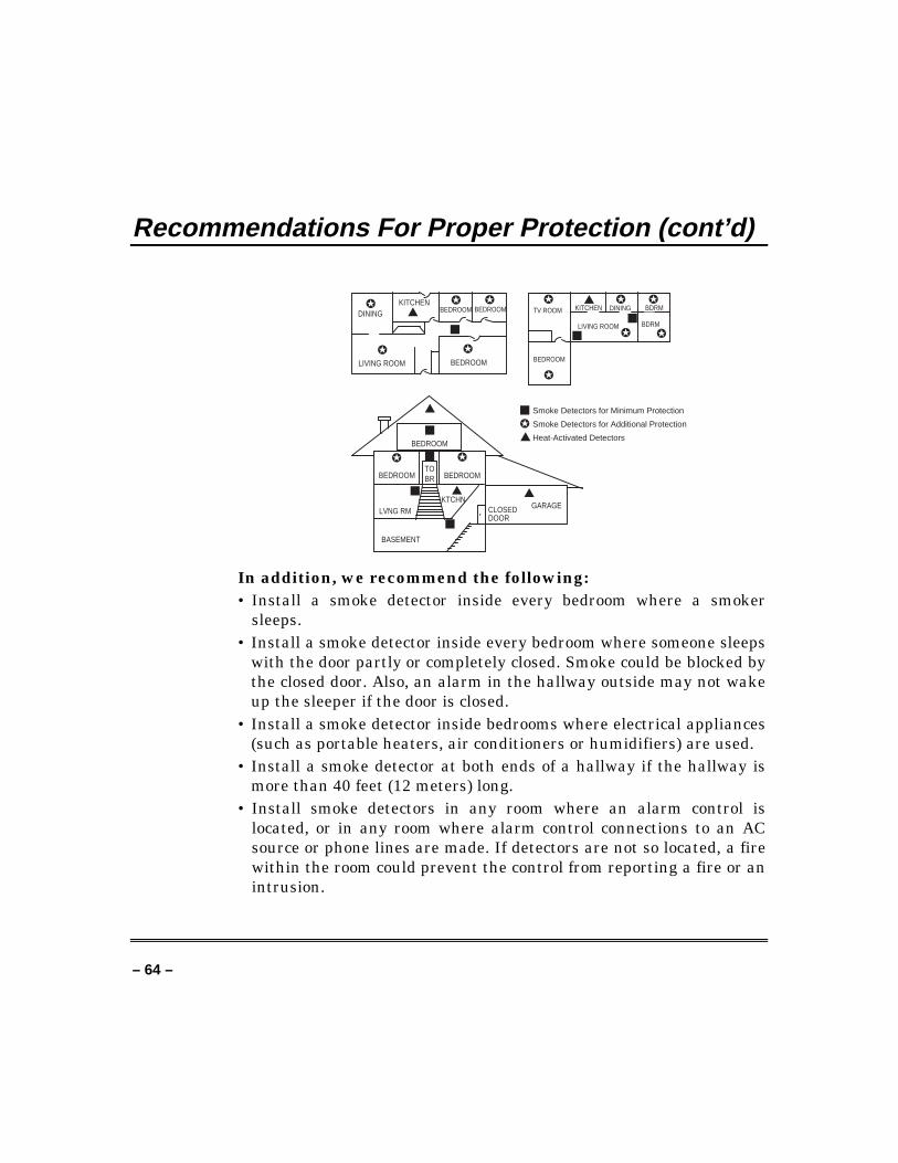
Smoke Detectors for Minimum Protection
Smoke Detectors for Additional Protection
Heat-Activated Detectors
In addition, we recommend the following:• Install a smoke detector inside every bedroom where a smoker
sleeps.• Install a smoke detector inside every bedroom where someone sleeps
with the door partly or completely closed. Smoke could be blocked bythe closed door. Also, an alarm in the hallway outside may not wakeup the sleeper if the door is closed.
• Install a smoke detector inside bedrooms where electrical appliances(such as portable heaters, air conditioners or humidifiers) are used.
• Install a smoke detector at both ends of a hallway if the hallway ismore than 40 feet (12 meters) long.
• Install smoke detectors in any room where an alarm control islocated, or in any room where alarm control connections to an ACsource or phone lines are made. If detectors are not so located, a firewithin the room could prevent the control from reporting a fire or anintrusion.
– 65 –
Recommendations For Proper Protection (cont’d)
Recommendations For Proper Intrusion Protection
For proper intrusion coverage, sensors should be located at everypossible point of entry to a home or commercial premises. This wouldinclude any skylights that may be present, and the upper windows ina multi-level building.
In addition, we recommend that radio backup be used in a securitysystem so that alarm signals can still be sent to the alarm monitoringstation in the event that the telephone lines are out of order (alarmsignals are normally sent over the phone lines, if connected to analarm monitoring station).
– 66 –
Emergency Evacuation
Establish and regularly practice a plan of escape in the event of fire. The followingsteps are recommended by the National Fire Protection Association:
1. Position your detector or your interior and/or exterior sounders sothat they can be heard by all occupants.
2. Determine two means of escape from each room. One path ofescape should lead to the door that permits normal exit from thebuilding. The other may be a window, should your path beimpassable. Station an escape ladder at such windows if there is along drop to the ground.
3. Sketch a floor plan of the building. Show windows, doors, stairsand rooftops that can be used to escape. Indicate escape routes foreach room. Keep these routes free from obstruction and post copiesof the escape routes in every room.
4. Assure that all bedroom doors are shut while you are asleep. Thiswill prevent deadly smoke from entering while you escape.
5. Try the door. If the door is hot, check your alternate escape route.If the door is cool, open it cautiously. Be prepared to slam the doorif smoke or heat rushes in.
6. Where smoke is present, crawl on the ground; do not walk upright.Smoke rises and may overcome you. Clearer air is near the floor.
7. Escape quickly; don't panic.
8. Establish a common meeting place outdoors, away from yourhouse, where everyone can meet and then take steps to contact theauthorities and account for those missing. Choose someone toassure that nobody returns to the house — many die going back.
– 67 –
Maintaining Your System
Taking Care of Your System
The components of your security system are designed to be as free ofmaintenance as possible. However, there are some things you can doto make sure that your system is in reliable working condition.
1. Test your system weekly.2. Test the system after any alarm occurs (see TESTING THE
SYSTEM).
Replacing Batteries in Wireless SensorsWireless sensorsmay not have beenused in yoursecurity system
Each wireless sensor in your system has a 9-volt or 3-volt battery. Thesystem detects a low battery in any wireless sensor, including smokedetectors, the optional personal emergency transmitter, and theoptional portable wireless keypad. (A low battery in a portable wirelesskeypad is detected as soon as one of its keys is pressed, and the keypadwill display 064.)
Alkaline batteries provide a minimum of one year of operation, and inmost units and applications, provide 2–4 years of service. Actualbattery life will depend on the environment in which the sensor isused, the number of signals that the transmitter in the sensor has hadto send, and the specific type of sensor. Factors such as humidity, highor low temperatures or large swings in temperature, may all lead tothe reduction of actual battery life in an installation.
If you have a low battery in a wireless sensor, a low batterymessage is displayed on the keypad.
In addition, a battery-operated smoke detector with a low battery alsoemits a single chirp sound once approximately every 20-30 seconds,identifying itself as the smoke detector with the weak battery. If youdo not replace a smoke detector's low battery, the smoke detector maysound continuously, as if there were a fire alarm.
– 68 –
Maintaining Your System (cont’d)Note: The low battery message comes on as a warning that batteryreplacement in indicated sensor(s) is due within 30 days. In themeantime, the sensor(s) causing the low battery indication is still fullyoperational.
Important: Use only batteries recommended by your installer asreplacement.
Silencing Low Battery Warning Tones at the Keypad
The keypad’s warning tones can be silenced by performing an Offsequence, [code] + [OFF], but the keypad's low battery messagedisplay will remain on as a reminder that you have a low batterycondition in one or more of your sensors. When you replace the weakbattery with a fresh one, the sensor will send a good battery signal tothe control as soon as the sensor is activated (opening/closing of door,window, etc.), causing the low battery display to turn off. If the sensoris not activated, the display will automatically clear withinapproximately one hour.
Routine Care
• Treat the components of your security system as you would anyother electrical equipment. Do not slam sensor-protected doors orwindows.
• Keep dust from accumulating on the keypad and all protectivesensors, particularly on motion sensors and smoke detectors.
• The keypad and sensors should be cleaned carefully with a dry softcloth. Do not spray water or any other fluid on the units.
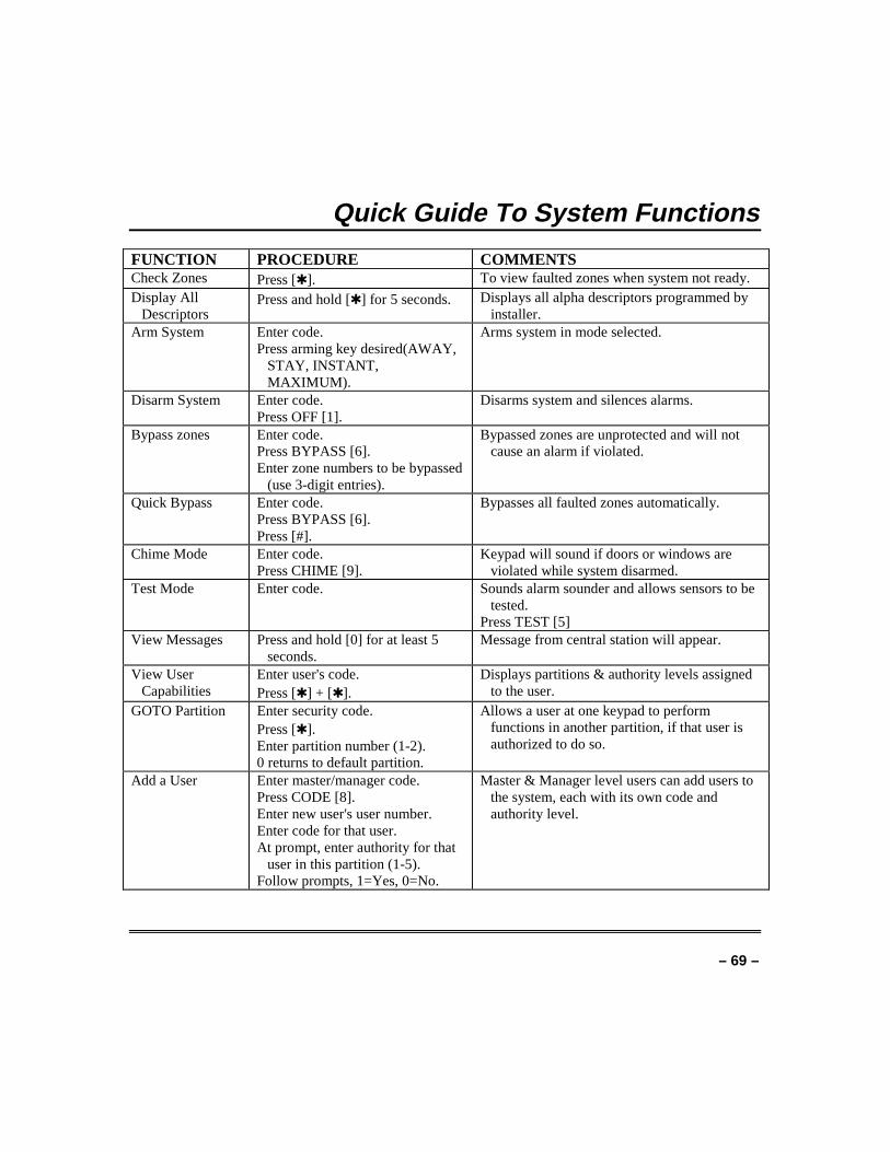
– 69 –
Quick Guide To System Functions
FUNCTION PROCEDURE COMMENTSCheck Zones Press [✱ ]. To view faulted zones when system not ready.Display All
DescriptorsPress and hold [✱ ] for 5 seconds. Displays all alpha descriptors programmed by
installer.Arm System Enter code.
Press arming key desired(AWAY,STAY, INSTANT,MAXIMUM).
Arms system in mode selected.
Disarm System Enter code.Press OFF [1].
Disarms system and silences alarms.
Bypass zones Enter code.Press BYPASS [6].Enter zone numbers to be bypassed
(use 3-digit entries).
Bypassed zones are unprotected and will notcause an alarm if violated.
Quick Bypass Enter code.Press BYPASS [6].Press [#].
Bypasses all faulted zones automatically.
Chime Mode Enter code.Press CHIME [9].
Keypad will sound if doors or windows areviolated while system disarmed.
Test Mode Enter code. Sounds alarm sounder and allows sensors to betested.
Press TEST [5]View Messages Press and hold [0] for at least 5
seconds.Message from central station will appear.
View UserCapabilities
Enter user's code.Press [✱ ] + [✱ ].
Displays partitions & authority levels assignedto the user.
GOTO Partition Enter security code.Press [✱ ].Enter partition number (1-2).0 returns to default partition.
Allows a user at one keypad to performfunctions in another partition, if that user isauthorized to do so.
Add a User Enter master/manager code.Press CODE [8].Enter new user's user number.Enter code for that user.At prompt, enter authority for that
user in this partition (1-5).Follow prompts, 1=Yes, 0=No.
Master & Manager level users can add users tothe system, each with its own code andauthority level.
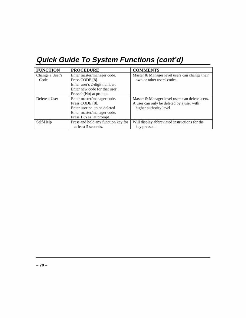
– 70 –
Quick Guide To System Functions (cont’d)FUNCTION PROCEDURE COMMENTSChange a User's
CodeEnter master/manager code.Press CODE [8].Enter user's 2-digit number.Enter new code for that user.Press 0 (No) at prompt.
Master & Manager level users can change theirown or other users' codes.
Delete a User Enter master/manager code.Press CODE [8].Enter user no. to be deleted.Enter master/manager code.Press 1 (Yes) at prompt.
Master & Manager level users can delete users.A user can only be deleted by a user with
higher authority level.
Self-Help Press and hold any function key forat least 5 seconds.
Will display abbreviated instructions for thekey pressed.
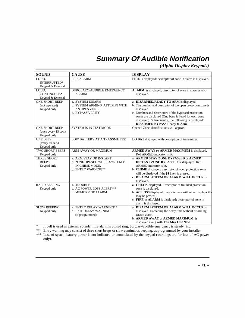
– 71 –
Summary Of Audible Notification(Alpha Display Keypads)
SOUND CAUSE DISPLAYLOUD,
INTERRUPTED*Keypad & External
FIRE ALARM FIRE is displayed; descriptor of zone in alarm is displayed.
LOUD,CONTINUOUS*Keypad & External
BURGLARY/AUDIBLE EMERGENCYALARM
ALARM is displayed; descriptor of zone in alarm is alsodisplayed.
ONE SHORT BEEP(not repeated)Keypad only
a. SYSTEM DISARMb. SYSTEM ARMING ATTEMPT WITH
AN OPEN ZONE.c. BYPASS VERIFY
a. DISARMED/READY TO ARM is displayed.b. The number and descriptor of the open protection zone is
displayed.c. Numbers and descriptors of the bypassed protection
zones are displayed (One beep is heard for each zonedisplayed). Subsequently, the following is displayed:DISARMED BYPASS Ready to Arm
ONE SHORT BEEP(once every 15 sec.)Keypad only
SYSTEM IS IN TEST MODE Opened Zone identifications will appear.
ONE BEEP(every 60 sec.)Keypad only
LOW BATTERY AT A TRANSMITTER LO BAT displayed with description of transmitter.
TWO SHORT BEEPSKeypad only
ARM AWAY OR MAXIMUM ARMED AWAY or ARMED MAXIMUM is displayed.Red ARMED indicator is lit.
THREE SHORTBEEPSKeypad only
a. ARM STAY OR INSTANTb. ZONE OPENED WHILE SYSTEM IS
IN CHIME MODE.c. ENTRY WARNING**
a. ARMED STAY ZONE BYPASSED or ARMEDINSTANT ZONE BYPASSED is displayed. RedARMED indicator is lit.
b. CHIME displayed, descriptor of open protection zonewill be displayed if the [✱ ] key is pressed.
c. DISARM SYSTEM OR ALARM WILL OCCUR isdisplayed.
RAPID BEEPINGKeypad only
a. TROUBLEb. AC POWER LOSS ALERT***c. MEMORY OF ALARM
a. CHECK displayed. Descriptor of troubled protectionzone is displayed.
b. AC LOSS displayed (may alternate with other displays thamay be present).
c. FIRE or ALARM is displayed; descriptor of zone inalarm is displayed.
SLOW BEEPINGKeypad only
a. ENTRY DELAY WARNING**b. EXIT DELAY WARNING
(if programmed)
a. DISARM SYSTEM OR ALARM WILL OCCUR isdisplayed. Exceeding the delay time without disarmingcauses alarm.
b. ARMED AWAY or ARMED MAXIMUM isdisplayed along with You May Exit Now
* If bell is used as external sounder, fire alarm is pulsed ring; burglary/audible emergency is steady ring.** Entry warning may consist of three short beeps or slow continuous beeping, as programmed by your installer.*** Loss of system battery power is not indicated or annunciated by the keypad (warnings are for loss of AC power
only).
– 72 –
Glossary
The following terms are used throughout the manual.
ARM/DISARM: Armed simply means that the burglary portion of yoursystem is turned on and is in a state of readiness. Disarmedmeans that the burglary system is turned off, and must berearmed to become operational. However, even in adisarmed state, emergency and fire portions of your systemare still operational.
KEYPAD: This is the area on your keypad containing numberedpushbuttons similar to those on telephones or calculators.These keys control the arming or disarming of the system,and perform other functions that were previously describedin this manual.
ZONE: A specific area of protection.
PARTITION: An independent group of zones that can be armed anddisarmed without affecting other zones or users.
BYPASS: To disarm a specific area of burglary protection whileleaving other areas operational.
DELAY ZONE: An area of protection containing doors most frequently usedto enter or exit (typically, a front door, back door, or doorfrom the garage into the building). The delay zone allowssufficient time for authorized entry or exit without causingan alarm. Consult your installer for the entry and exitdelay times that have been set for your system duringinstallation and record them on the separate sheet providedin this manual.
DAY/NIGHT ZONE: An area of protection whose violation causes a troubleindication during the disarmed (Day) mode and an alarmduring the armed (Night) mode.
– 73 –
UL NOTICE: This is a “GRADE A” system.“FEDERAL COMMUNICATIONS COMMISSION (FCC) Part 15 STATEMENT”
This equipment has been tested to FCC requirements and has been found acceptable for use. The FCC requires thefollowing statement for your information:
This equipment generates and uses radio frequency energy and if not installed and used properly, that is, in strictaccordance with the manufacturer’s instructions, may cause interference to radio and television reception. It has beentype tested and found to comply with the limits for a Class B computing device in accordance with the specifications inPart 15 of FCC Rules, which are designed to provide reasonable protection against such interference in a residentialinstallation. However, there is no guarantee that interference will not occur in a particular installation. If thisequipment does cause interference to radio or television reception, which can be determined by turning the equipmentoff and on, the user is encouraged to try to correct the interference by one or more of the following measures:
• If using an indoor antenna, have a quality outdoor antenna installed.
• Reorient the receiving antenna until interference is reduced or eliminated.
• Move the receiver away from the control/communicator.
• Move the antenna leads away from any wire runs to the control/communicator.
• Plug the control/communicator into a different outlet so that it and the receiver are on different branch circuits.If necessary, the user should consult the dealer or an experienced radio/television technician for additional suggestions.The user or installer may find the following booklet prepared by the Federal Communications Commission helpful:“Interference Handbook”This booklet is available from the U.S. Government Printing Office, Washington, DC 20402.
The user shall not make any changes or modifications to the equipment unless authorized by the InstallationInstructions or User’s Manual. Unauthorized changes or modifications could void the user’s authority to operate theequipment.
IN THE EVENT OF TELEPHONE OPERATIONAL PROBLEMSIn the event of telephone operational problems, disconnect the control by removing the plug from the RJ31X (CA38Ain Canada) telephone wall jack. We recommend that your certified installer demonstrate disconnecting the phones oninstallation of the system. Do not disconnect the phone connection inside the control/communicator. Doing so willresult in the loss of your phone lines. If the regular phone works correctly after the control/communicator has beendisconnected from the phone lines, the control/communicator has a problem and should be returned for repair. If upondisconnection of the control/communicator, there is still a problem on the line, notify the telephone company that theyhave a problem and request prompt repair service. The user may not under any circumstances (in or out of warranty)attempt any service or repairs to the system. It must be returned to the factory or an authorized service agency for allrepairs.
– 74 –
“FEDERAL COMMUNICATIONS COMMISSION (FCC) Part 68 NOTICEThis equipment complies with Part 68 of the FCC rules. On the front cover of this equipment is a label thatcontains, among other information, the FCC registration number and ringer equivalence number (REN) forthis equipment. If requested, this information must be provided to the telephone company.
This equipment uses the following jacks:
An RJ31X is used to connect this equipment to the telephone network.
The REN is used to determine the quantity of devices which may be connected to the telephone line.Excessive RENs on the telephone line may result in the devices not ringing in response to an incoming call.In most, but not all areas, the sum of the RENs should not exceed five (5.0). To be certain of the number ofdevices that may be connected to the line, as determined by the total RENs, contact the telephone companyto determine the maximum REN for the calling area.
If this equipment causes harm to the telephone network, the telephone company will notify you in advancethat temporary discontinuance of service may be required. If advance notice is not practical, the telephonecompany will notify the customer as soon as possible. Also, you will be advised of your right to file acomplaint with the FCC if you believe necessary.
The telephone company may make changes in its facilities, equipment, operations, or procedures that couldaffect the operation of the equipment. If this happens, the telephone company will provide advance noticein order for you to make the necessary modifications in order to maintain uninterrupted service.
If trouble is experienced with this equipment, please contact the manufacturer for repair and warrantyinformation. If the trouble is causing harm to the telephone network, the telephone company may requestyou remove the equipment from the network until the problem is resolved.
There are no user serviceable components in this product, and all necessary repairs must be made by themanufacturer. Other repair methods may invalidate the FCC registration on this product.
This equipment cannot be used on telephone company-provided coin service. Connection to Party LineService is subject to state tariffs.
This equipment is hearing-aid compatible.
When programming or making test calls to an emergency number, briefly explain to the dispatcher thereason for the call. Perform such activities in the off-peak hours; such as early morning or late evening.
– 75 –
CANADIAN DEPARTMENT OF COMMUNICATIONS(DOC) STATEMENT
NOTICE
The Canadian Department of Communications labelidentifies certified equipment. This certification means thatthe equipment meets certain telecommunications networkprotective, operational and safety requirements. TheDepartment does not guarantee the equipment will operate tothe user’s satisfaction.
Before installing this equipment, users should ensure that itis permissible to be connected to the facilities of the localtelecommunications company. The equipment must also beinstalled using an acceptable method of connection. In somecases, the company’s inside wiring associated with a singleline individual service may be extended by means of certifiedconnector assembly (telephone extension cord). Thecustomer should be aware that compliance with the aboveconditions may not prevent degradation of service in somesituations.
Repairs to certified equipment should be made by anauthorized Canadian maintenance facility designated by thesupplier. Any repairs or alterations made by the user to thisequipment, or equipment malfunctions, may give thetelecommunications company cause to request the user todisconnect the equipment.
Users should ensure for their own protection that theelectrical ground connections of the power utility, telephonelines and internal metallic water pipe system, if present, areconnected together. This precaution may be particularlyimportant in rural areas.
Caution: User should not attempt to make such connectionsthemselves, but should contact the appropriate electricinspection authority, or electrician, as appropriate.The Load Number (LN) assigned to each terminal devicedenotes the percentage of the total load to be connected to atelephone loop which is used by the device, to preventoverloading. The termination on a loop may consist of anycombination of devices subject only to the requirement thatthe total of the Load Numbers of all the devices does notexceed 100.
AVIS
L’étiquette du ministère des Communications du Canada identifiele matériel homologué. Cette étiquette certifie que le matériel estconforme à certaines normes de protection, d’exploitation et desécurité des réseaux de télécommunications. Le ministère n’assuretoutefois pas que le matériel fonctionnera à la satisfaction del’utilisateur.
Avant d’installer ce matériel, l’utilisateur doit s’assurer qu’il estpermis de le raccorder aux installations de l’entreprise locale detélécommunications. Le matériel doit également être installé ensuivant une méthode acceptée de raccordement. Dans certains cas,les fils intérieurs de l’entreprise utilisés pour un service individuelà la ligne unique peuvent être prolongés au moyen d’un dispositifhomologué de raccordement (cordon prolongateur téléphoniqueinterne). L’abonné ne doit pas oublier qu’il est possible que laconformité aux conditions énoncées ci-dessus n’empèchet pas ladégradation du service dans certaines situations. Actuellement, lesentreprises de télécommunications ne permettent pas que l’onraccorde leur matériel aux prises d’abonnés, sauf dans les casprecis prévus par les tarifs particuliers de ces entreprises.
Les réparations du matériel homologué doivent être effectuées pasun centre d’entretien canadien autorisé désigné par le fournisseur.La compagnie de télécommunications peut demander àl’utilisateur de débrancher un appareil à la suite de réparations oude modifications effectuées par l’utilisateur ou à cause de mauvaisfonctionnement.
Pour sa propre protection, l’utilisateur doit s’assurer que tous lesfils de mise en terre de la source d’énergie électrique, des lignestéléphoniques de réseau de conduites d’eau s’il y en a, soientraccordés ensemble. Cette précaution est particulièrementimportante dans les régions rurales.
Avertissement: L’utilisateur ne doit pas tenter de faire cesraccordements lui-même; il doit avoir recours à un serviced’inspection des installations électriques, ou à un électricien, selonle cas.
L’indice de charge (IC) assigné à chaque dispositif terminal pouréviter toute surcharge indique le pourcentage de la charge totalequi peut être raccordé à un circuit téléphonique bouclé utilisé parce dispositif. La terminaison du circuit bouclé peut être constituéede n’importe quelle combinaison de dispositifs, pourvu que lasomme des indices de charge de l’ensemble des dispositifs nedépasse pas 100.
– 76 –
WARNING!THE LIMITATIONS OF THIS ALARM SYSTEM
While this system is an advanced design security system, it does not offer guaranteed protection against burglary or fireor other emergency. Any alarm system, whether commercial or residential, is subject to compromise or failure to warnfor a variety of reasons. For example:• Intruders may gain access through unprotected openings or have the technical sophistication to bypass an alarm
sensor or disconnect an alarm warning device.• Intrusion detectors (e.g. passive infrared detectors), smoke detectors, and many other sensing devices will not work
without power. Battery operated devices will not work without batteries, with dead batteries, or if the batteries arenot put in properly. Devices powered solely by AC will not work if their AC power supply is cut off for any reason,however briefly.
• Signals sent by wireless transmitters may be blocked or reflected by metal before they reach the alarm receiver. Evenif the signal path has been recently checked during a weekly test, blockage can occur if a metal object is moved intothe path.
• A user may not be able to reach a panic or emergency button quickly enough.• While smoke detectors have played a key role in reducing residential fire deaths in the United States, they may not
activate or provide early warning for a variety of reasons in as many as 35% of all fires, according to data publishedby the Federal Emergency Management Agency. Some of the reasons smoke detectors used in conjunction with thisSystem may not work are as follows. Smoke detectors may have been improperly installed and positioned. Smokedetectors may not sense fires that start where smoke cannot reach the detectors, such as in chimneys, in walls, orroofs, or on the other side of closed doors. Smoke detectors also may not sense a fire on another level of a residenceor building. A second floor detector, for example, may not sense a first floor or basement fire. Moreover, smokedetectors have sensing limitations. No smoke detector can sense every kind of fire every time. In general, detectorsmay not always warn about fires caused by carelessness and safety hazards like smoking in bed, violent explosions,escaping gas, improper storage of flammable materials, overloaded electrical circuits, children playing with matches,or arson. Depending upon the nature of the fire and/or the locations of the smoke detectors, the detector, even if itoperates as anticipated, may not provide sufficient warning to allow all occupants to escape in time to prevent injuryor death.
• Passive Infrared Motion Detectors can only detect intrusion within the designed ranges as diagrammed in theirinstallation manual. Passive Infrared Detectors do not provide volumetric area protection. They do create multiplebeams of protection, and intrusion can only be detected in unobstructed areas covered by those beams. They cannotdetect motion or intrusion that takes place behind walls, ceilings, floors, closed doors, glass partitions, glass doors, orwindows. Mechanical tampering, masking, painting or spraying of any material on the mirrors, windows or any partof the optical system can reduce their detection ability. Passive Infrared Detectors sense changes in temperature;however, as the ambient temperature of protected area approaches the temperature range of 90° to 105°F, thedetection performance can decrease.
– 77 –
WARNING!THE LIMITATIONS OF THIS ALARM SYSTEM
(continued)• Alarm warning devices such as sirens, bells or horns may not alert people or wake up sleepers if they are located on
the other side of closed or partly open doors. If warning devices sound on a different level of the residence from thebedrooms, then they are less likely to waken or alert people inside the bedrooms. Even persons who are awake maynot hear the warning if the alarm is muffled from a stereo, radio, air conditioner or other appliance, or by passingtraffic. Finally, alarm warning devices, however loud, may not warn hearing-impaired people or waken deepsleepers.
• Telephone lines needed to transmit alarm signals from a premises to a central monitoring station may be out ofservice or temporarily out of service. Telephone lines are also subject to compromise by sophisticated intruders.
• Even if the system responds to the emergency as intended, however, occupants may have insufficient time to protectthemselves from the emergency situation. In the case of a monitored alarm system, authorities may not respondappropriately.
• This equipment, like other electrical devices, is subject to component failure. Even though this equipment isdesigned to last as long as 10 years, the electronic components could fail at any time.
The most common cause of an alarm system not functioning when an intrusion or fire occurs is inadequatemaintenance. This alarm system should be tested weekly to make sure all sensors and transmitters are workingproperly.Installing an alarm system may make one eligible for lower insurance rates, but an alarm system is not a substitute forinsurance. Homeowners, property owners and renters should continue to act prudently in protecting themselves andcontinue to insure their lives and property.We continue to develop new and improved protection devices. Users of alarm systems owe it to themselves and theirloved ones to learn about these developments.
–78–
Index
#70 command ........................................444285 or 4286 VIP module .................8, 44AC Loss..................................................62Access Another Partition......................22Access Door............................................43Add a User.............................................18ADD NEW USER..................................20Add User Code ......................................17Ademco Dealer ......................................62Alarm .......................................................6Alkaline batteries..................................67Alpha Keypads ......................................10Armed ......................................................5ARMED INDICATOR...........................13Audible Emergency...............................40Audible Signals .....................................71Authority Level .....................................15Authority Levels .............................16, 17Away ..................................................5, 22AWAY ....................................................37AWAY mode ..........................................34battery life .............................................67Burglary...................................................4Burglary Protection ................................5Bypass Zones.........................................30Bypassing ..............................................30Call Service ...........................................60Change a User's Code ...........................20Change User Code ................................17CHECK..................................................60Chime.................................................5, 38Closing Time .........................................46Comm. Failure ......................................61Common Lobby......................................25Delaying Closing Time .........................46Delete a User.........................................21Delete User Code ..................................17
Descriptors............................................ 29Device Timers ................................... 7, 50Disarm................................................... 36DOC....................................................... 75Duress ................................................... 16Duress Code.......................................... 15Emergency .............................................. 4Entry Delay .......................................... 14Entry/Exit ............................................... 5Event Log Procedures .......................... 53Exit Delay ............................................. 14Exit User Edit Mode ............................ 18FCC ....................................................... 73Fire .................................................... 4, 40fire alarm .............................................. 57Fire Display Lock ................................. 58FIRE DRILL ACTIVE.......................... 58Fire Drill Test....................................... 58Fire Protection........................................ 5GLOBAL ARM...................................... 19Global Arming ...................................... 22Glossary ................................................ 72Goto ....................................................... 19GOTO .................................................... 22GOTO Command.................................... 7HSENS.................................................. 61Instant............................................... 5, 22INSTANT.............................................. 14INSTANT mode.................................... 33Keypad .................................................... 4Keypad back lighting ........................... 10Keypad Functions................................. 12Keypads................................................. 10Keyswitch.............................................. 37LO Bat................................................... 61Low Battery .......................................... 67Low Battery Warning .......................... 68
– 79 –
LSENS ...................................................61macro .....................................................41Macros......................................................6Manager.................................................16Master....................................................16Master Keypad..................................8, 23Maximum ..........................................5, 22MAXIMUM............................................14MAXIMUM mode..................................35Memory of Alarm ..............................6, 36Messages................................................39Modem Comm .......................................61MULTI-ACCESS...................................19NFPA .....................................................63Not Ready ..............................................28Off ..........................................................22OFF........................................................36Open Zones............................................28Open/Close Schedules...........................46Operator A.............................................16Operator B.............................................16Operator C.............................................16OUTPUT TIMER ..................................50Panic Keys .............................................40PANIC KEYS ........................................13Partitioned Security System ..................4Partitioned System .................................4Personal Emergency .............................40Phone Access ...........................................8Power .....................................................62POWER/READY INDICATOR.............13Quick Arm .............................................13Quick Arming ........................................15Quick Bypass.........................................31Quick Guide...........................................69Ready .....................................................28READY ..................................................38
Ready Key............................................. 28Relay Menu Mode................................. 44Replacing Batteries.............................. 67RF BUTTON......................................... 19Routine Care......................................... 68Schedules .......................................... 7, 46Security Code........................................ 16Security Codes...................................... 15Sensing Devices...................................... 5Silencing A Fire Alarm ........................ 57Silent Emergency ................................. 40Smoke Detectors................................... 56Speed Key ............................................. 41SPEED KEY ........................................... 6Stay ................................................... 5, 22STAY ..................................................... 37STAY mode ........................................... 32System LO Bat ..................................... 61System Overview.................................... 4Temporary Schedules..................... 46, 47Temporary Users.................................. 18Test Key ................................................ 55Test mode.............................................. 55Testing Your System............................ 56Time Window........................................ 47TRBL..................................................... 60Trouble Condition................................. 60UNABLE TO ARM LOBBY................. 26User Edit Mode..................................... 17User Numbers ...................................... 15User's Instructions ................................. 8WARRANTY ......................................... 80Wireless Sensor .................................... 67Zone Bypassed ...................................... 32Zone Descriptors................................... 29Zones ....................................................... 5
��������K3522 3/99
ADEMCO ONE YEAR LIMITED WARRANTYAlarm Device Manufacturing Company, a Division of Pittway Corporation, and its divisions, subsidiaries and affiliates(“Seller”), 165 Eileen Way, Syosset, New York 11791, warrants its security equipment (the “product”) to be free fromdefects in materials and workmanship for one year from date of original purchase, under normal use and service.Seller’s obligation is limited to repairing or replacing, at its option, free of charge for parts, labor, or transportation, anyproduct proven to be defective in materials or workmanship under normal use and service. Seller shall have noobligation under this warranty or otherwise if the product is altered or improperly repaired or serviced by anyone otherthan the Seller. In case of defect, contact the security professional who installed and maintains your security equipmentor the Seller for product repair.
This one year Limited Warranty is in lieu of all other express warranties, obligations or liabilities. THERE ARE NOEXPRESS WARRANTIES, WHICH EXTEND BEYOND THE FACE HEREOF. ANY IMPLIED WARRANTIES,OBLIGATIONS OR LIABILITIES MADE BY SELLER IN CONNECTION WITH THIS PRODUCT, INCLUDINGANY IMPLIED WARRANTY OF MERCHANTABILITY, OR FITNESS FOR A PARTICULAR PURPOSE OROTHERWISE, ARE LIMITED IN DURATION TO A PERIOD OF ONE YEAR FROM THE DATE OF ORIGINALPURCHASE. ANY ACTION FOR BREACH OF ANY WARRANTY, INCLUDING BUT NOT LIMITED TO ANYIMPLIED WARRANTY OF MERCHANTABILITY, MUST BE BROUGHT WITHIN 12 MONTHS FROM DATEOF ORIGINAL PURCHASE. IN NO CASE SHALL SELLER BE LIABLE TO ANYONE FOR ANYCONSEQUENTIAL OR INCIDENTAL DAMAGES FOR BREACH OF THIS OR ANY OTHER WARRANTY,EXPRESS OR IMPLIED, OR UPON ANY OTHER BASIS OF LIABILITY WHATSOEVER, EVEN IF THE LOSSOR DAMAGE IS CAUSED BY THE SELLER’S OWN NEGLIGENCE OR FAULT. Some states do not allowlimitation on how long an implied warranty lasts or the exclusion or limitation of incidental or consequential damages,so the above limitation or exclusion may not apply to you.
Seller does not represent that the product may not be compromised or circumvented; that the product will prevent anypersonal injury or property loss by burglary, robbery, fire or otherwise; or that the product will in all cases provideadequate warning or protection. Buyer understands that a properly installed and maintained alarm may only reduce therisk of a burglary, robbery, fire or other events occurring without providing an alarm, but it is not insurance or aguarantee that such will not occur or that there will be no personal injury or property loss as a result.CONSEQUENTLY, SELLER SHALL HAVE NO LIABILITY FOR ANY PERSONAL INJURY, PROPERTYDAMAGE OR OTHER LOSS BASED ON A CLAIM THE PRODUCT FAILED TO GIVE WARNING. HOWEVER,IF SELLER IS HELD LIABLE, WHETHER DIRECTLY OR INDIRECTLY, FOR ANY LOSS OR DAMAGEARISING UNDER THIS LIMITED WARRANTY OR OTHERWISE, REGARDLESS OF CAUSE OR ORIGIN,SELLER'’ MAXIMUM LIABILITY SHALL NOT IN ANY CASE EXCEED THE PURCHASE PRICE OF THEPRODUCT, WHICH SHALL BE THE COMPLETE AND EXCLUSIVE REMEDY AGAINST SELLER. Thiswarranty gives you specific legal rights, and you may also have other rights which vary from state to state. No increaseor alteration, written or verbal, to this warranty is authorized.
165 Eileen Way, Syosset, NY 11791Copyright 1999 PITTWAY Corporation